attocube controller anc150 manual
DESCRIPTION
sssTRANSCRIPT

Version: 2.4 Modified: January 09 Products: ANC150/1, ANC150/3, ANC150/6
User Manual
Piezo Step Controller ANC150
attocube systems AG, Königinstrasse 11a (Rgb), D - 80539 München Germany Phone: +49 89-2877 80915 Fax: +49 89-2877 80919 E-Mail: [email protected] www.attocube.com
For technical queries, contact: [email protected] attocube systems office Munich: Phone +49 89 2877 80915 Fax +49 89 2877 80919

Page 2
Part of the software embedded in this product is eCos - Embedded Configurable Operating System, a trademark of Red Hat. Portions created by Red Hat are Copyright (C) 1998, 1999, 2000 Red Hat, Inc. (http://www.redhat.com/). All Rights Reserved.
THE SOFTWARE IN THIS PRODUCT WAS IN PART PROVIDED BY RED HAT AND ANY EXPRESS OR IMPLIED WARRANTIES, INCLUDING, BUT NOT LIMITED TO, THE IMPLIED WARRANTIES OF MERCHANTABILITY AND FITNESS FOR A PARTICULAR PURPOSE ARE DISCLAIMED. IN NO EVENT SHALL THE AUTHOR BE LIABLE FOR ANY DIRECT, INDIRECT, INCIDENTAL, SPECIAL, EXEMPLARY, OR CONSEQUENTIAL DAMAGES (INCLUDING, BUT NOT LIMITED TO, PROCUREMENT OF SUBSTITUTE GOODS OR SERVICES; LOSS OF USE, DATA, OR PROFITS; OR BUSINESS INTERRUPTION) HOWEVER CAUSED AND ON ANY THEORY OF LIABILITY, WHETHER IN CONTRACT, STRICT LIABILITY, OR TORT (INCLUDING NEGLIGENCE OR OTHERWISE) ARISING IN ANY WAY OUT OF THE USE OF THIS SOFTWARE, EVEN IF ADVISED OF THE POSSIBILITY OF SUCH DAMAGE.
LabViewTM is a trademark of National Instruments Corporation.
Page 3
© 2001-2009 attocube systems AG. Product and company names listed are trademarks or trade names of their respective companies. Any rights not expressly granted herein are reserved. ATTENTION: Specifications and technical data are subject to change without notice.
Table of Contents
Table of Contents .............................................................................. 3
I. Introduction .......................................................................... 4 I.1. System Overview ................................................................. 4 I.2. Safety Information .............................................................. 5
I.2.a. Warnings .................................................................... 6 I.3. Declarations of Conformity ................................................... 7 I.4. Waste Electrical and Electronic Equipment (WEEE) Directive ......... 8
II. Setup Procedure ...................................................................... 9 II.1. Mechanical Installation ........................................................ 9 II.2. Electrical Installation ........................................................ 10
II.2.a. Connecting to the Voltage Supply ................................. 10 II.2.b. Fuses ..................................................................... 10
II.3. Front Panel Controls and Indicators ...................................... 11 II.4. Rear Panel Connections ...................................................... 12 II.5. Pin Assignment ................................................................ 13
II.5.a. RS 232 Connector ...................................................... 13 II.5.b. TTL Connector .......................................................... 13
III. Description of the Controller and General Use .............................. 14
IV. Remote Control of the ANC150 ................................................. 16 IV.1. Connecting the ANC150 ..................................................... 16 IV.2. Remote Control Commands ................................................. 17 IV.3. Fast Commands ................................................................ 19 IV.4. LabView™ Drivers.............................................................. 20 IV.5. Pattern Definition ............................................................. 21 IV.6. Programming New Patterns ................................................. 23
IV.6.a. Resetting the Pattern Memory ..................................... 24 IV.7. Maintaining the Voltage after a Step ..................................... 24 IV.8. Optional TTL Input ............................................................ 26 IV.9. Firmware Upgrade ............................................................. 27
V. Preventive Maintenance .......................................................... 28 V.1. Safety Testing .................................................................. 28 V.2. Fuses ............................................................................. 28 V.3. Cleaning ......................................................................... 28
VI. Questions & Answers .............................................................. 29

Page 4
I. Introduction
I.1. System Overview
The Piezo Step Controller ANC150 is a positioner control unit providing the suitable drive pulses to actuate attocube systems positioners manually or under computer control. It enables performing single as well as continuous stepping, either by hand or by remote control. Additionally, it enables measurement of the capacitance, which is a basic indicator for a working system.
The ANC150 is available as single axis electronics ANC150/1, three axes electronics ANC150/3. For the six axes electronics ANC150/6, an additional output relay is introduced, which switches between two sets of output axes (1 - 3 or 4 - 6).
The attocube systems positioners are to be connected to the outputs of the ANC150 using either the cable delivered with the system for table-top applications, or by using user supplied cabling for applications in extreme environments such as low temperatures or ultra-high vacuum. Please refer to the sections below for a description of the respective cabling requirements.
Page 5
© 2001-2009 attocube systems AG. Product and company names listed are trademarks or trade names of their respective companies. Any rights not expressly granted herein are reserved. ATTENTION: Specifications and technical data are subject to change without notice.
I.2. Safety Information
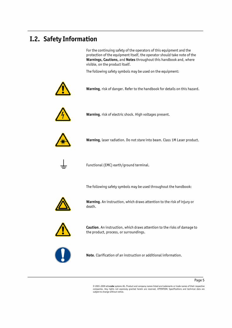
For the continuing safety of the operators of this equipment and the protection of the equipment itself, the operator should take note of the Warnings, Cautions, and Notes throughout this handbook and, where visible, on the product itself.
The following safety symbols may be used on the equipment:
Warning, risk of danger. Refer to the handbook for details on this hazard.
Warning, risk of electric shock. High voltages present.
Warning, laser radiation. Do not stare into beam. Class 1M Laser product.
Functional (EMC) earth/ground terminal.
The following safety symbols may be used throughout the handbook:
Warning. An instruction, which draws attention to the risk of injury or death.
Caution. An instruction, which draws attention to the risks of damage to the product, process, or surroundings.
Note. Clarification of an instruction or additional information.

Page 6
I.2.a. Warnings
The unit must be connected only to an earthed fused supply of 110 to 230 V.
Warning. The equipment, as described herein, is designed for use by personnel properly trained in the use and handling of mains powered electrical equipment. Only personnel trained in the servicing and maintenance of this equipment should remove its covers or attempt any repairs or adjustments. If malfunction is suspected, immediately return the part to attocube systems for repair or replacement. There are no user-serviceable parts inside the electronics. Modified or opened electronics cannot be covered by the attocube warranty anymore. Take special care if connecting products from other manufacturers. Follow the General Accident Prevention Rules.
Warning. The piezo translators and controllers, as described herein, are high voltage devices, capable of generating high output currents. They may cause serious or even lethal injuries if used improperly. Do never touch any part that might have connection to the high voltage output. Working with high voltage devices requires adequately educated operating personnel.
Warning. If this equipment is used in a manner not specified by the manufacturer, the protection provided by the equipment may be impaired. Do not operate the instrument outside its rated supply voltages or environmental range. In particular, excessive moisture may impair safety.
Caution. Never connect any cabling to the electronics when contacts are exposed! Never connect any cabling to the electronics when the electronics is not in GND mode! The scan piezos at the heart of a positioner unit are high voltage components and can cause serious injuries. Avoid short-cuts. Be careful not to cause a short-cut between the contacts in the BNC or any other connectors.
Caution. For laboratory use only. This unit is intended for operation from a normal, single phase supply, in the temperature range 5° to 40°C, 20% to 80% RH.
Page 7
© 2001-2009 attocube systems AG. Product and company names listed are trademarks or trade names of their respective companies. Any rights not expressly granted herein are reserved. ATTENTION: Specifications and technical data are subject to change without notice.
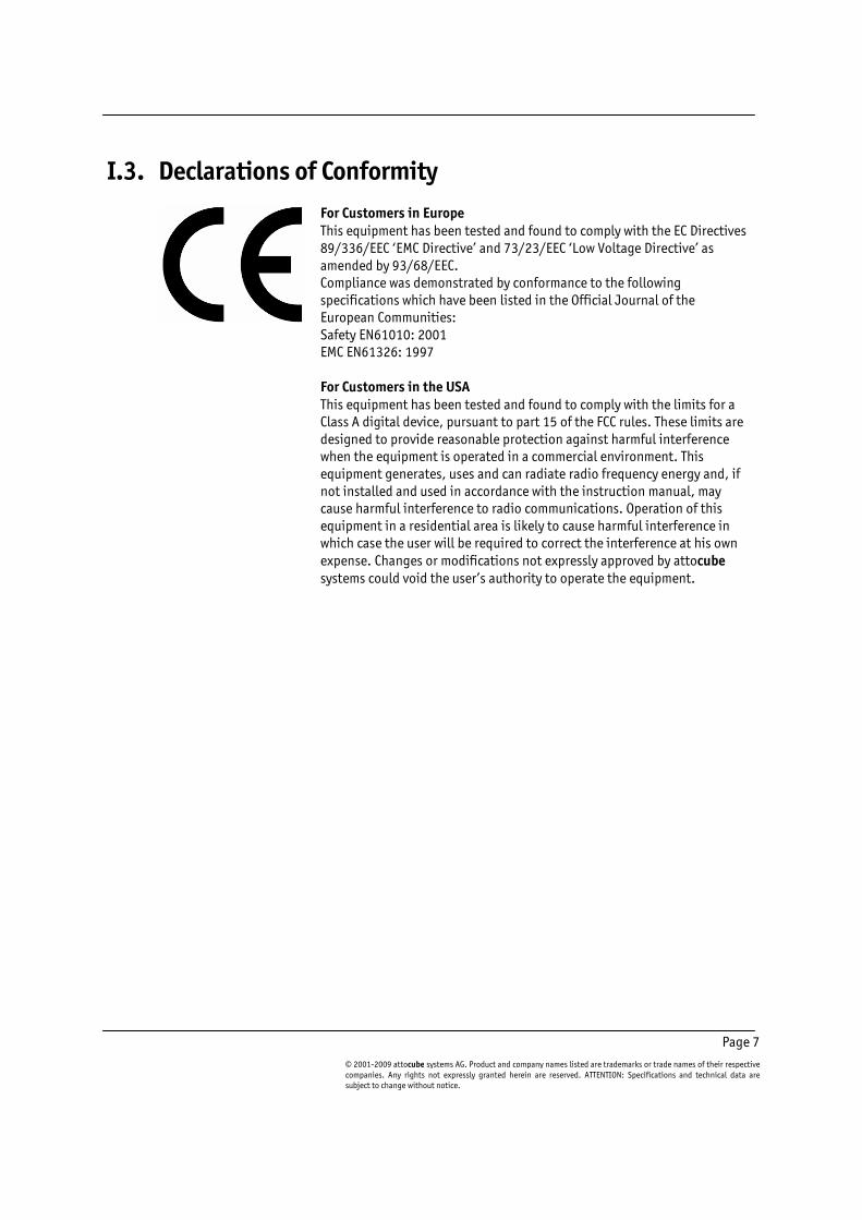
I.3. Declarations of Conformity
For Customers in Europe This equipment has been tested and found to comply with the EC Directives 89/336/EEC ‘EMC Directive’ and 73/23/EEC ‘Low Voltage Directive’ as amended by 93/68/EEC. Compliance was demonstrated by conformance to the following specifications which have been listed in the Official Journal of the European Communities: Safety EN61010: 2001 EMC EN61326: 1997 For Customers in the USA This equipment has been tested and found to comply with the limits for a Class A digital device, pursuant to part 15 of the FCC rules. These limits are designed to provide reasonable protection against harmful interference when the equipment is operated in a commercial environment. This equipment generates, uses and can radiate radio frequency energy and, if not installed and used in accordance with the instruction manual, may cause harmful interference to radio communications. Operation of this equipment in a residential area is likely to cause harmful interference in which case the user will be required to correct the interference at his own expense. Changes or modifications not expressly approved by attocube systems could void the user’s authority to operate the equipment.

Page 8
I.4. Waste Electrical and Electronic Equipment (WEEE) Directive
DE16963721
Compliance As required by the Waste Electrical and Electronic Equipment (WEEE) Directive of the European Community and the corresponding national laws, attocube systems offers all end users in the EC the possibility to return "end of life" units without incurring disposal charges. This offer is valid for attocube systems electrical and electronic equipment:
• sold after August 13th 2005,
• marked correspondingly with the crossed out "wheelie bin" logo (see logo to the left),
• sold to a company or institute within the EC,
• currently owned by a company or institute within the EC,
• still complete, not disassembled, and not contaminated.
As the WEEE directive applies to self contained operational electrical and electronic products, this "end of life" take back service does not refer to other attocube products, such as
• pure OEM products, that means assemblies to be built into a unit by the user (e. g. OEM electronic drivers),
• components,
• mechanics and optics,
• left over parts of units disassembled by the user (PCB's, housings etc.).
If you wish to return an attocube unit for waste recovery, please contact attocube systems or your nearest dealer for further information.
Waste treatment on your own responsibility If you do not return an "end of life" unit to attocube systems, you must hand it to a company specialized in waste recovery. Do not dispose of the unit in a litter bin or at a public waste disposal site.
Ecological background It is well known that WEEE pollutes the environment by releasing toxic products during decomposition. The aim of the European RoHS directive is to reduce the content of toxic substances in electronic products in the future. The intent of the WEEE directive is to enforce the recycling of WEEE. A controlled recycling of end of live products will thereby avoid negative impacts on the environment.

Page 9
© 2001-2009 attocube systems AG. Product and company names listed are trademarks or trade names of their respective companies. Any rights not expressly granted herein are reserved. ATTENTION: Specifications and technical data are subject to change without notice.
II.Setup Procedure
II.1. Mechanical Installation
Siting
Carefully unpack and visually inspect the controller and stages for any damage. Place all components on a flat and clean surface.
Caution. When siting the unit, it should be positioned so as not to impede the operation of the rear panel power supply plug and switch. Ensure that proper airflow is maintained to the unit. Do not obscure the ventilation holes
Warning. Operation outside the following environmental limits may adversely affect operator safety:
• Indoor use only
• Maximum altitude 2000 m
• Temperature range 5°C to 40°C
• Maximum humidity less than 80% RH (non-condensing) at 31°C
To ensure reliable operation the unit should not be exposed to corrosive agents or excessive moisture, heat or dust. If the unit has been stored at a low temperature or in an environment of high humidity, it must be allowed to reach ambient conditions before being powered up.
Caution. In applications requiring the highest level of accuracy and repeatability, it is recommended that the controller unit is powered up approximately 30 minutes before use, in order to allow the internal temperature to stabilize.
Caution. Do not connect cabling longer than 3m. Longer cabling may increase the sensitivity of the device to external influences.

Page 10
II.2. Electrical Installation
II.2.a. Connecting to the Voltage Supply
Warnings.
• The unit must be connected only to an earthed fused supply of 110 to 230V.
• Use only power supply cables supplied by attocube systems, other cables may not be rated to the same current. The unit is shipped with appropriate power cables for use in the UK, Europe, and the USA. When shipped to other territories the appropriate power plug must be fitted by the user.
II.2.b. Fuses
A T 1 A/250 V fuse is located on the back panel for the mains voltage. An additional fuse for the 70 V supply voltage is placed on the back of the electronics (FU4: T 500 mA / 250 V)
Note. When replacing fuses:
1) Switch off the power and disconnect the power cord before removing the fuse cover.
2) Always replace broken fuses with a fuse of the same rating and type.

Page 11
© 2001-2009 attocube systems AG. Product and company names listed are trademarks or trade names of their respective companies. Any rights not expressly granted herein are reserved. ATTENTION: Specifications and technical data are subject to change without notice.
II.3. Front Panel Controls and Indicators
Figure 1: Front panel of the ANC 150/1.
Figure 2: Front panel of the ANC 150/3. There are three independent modules for all three axes.
On the front panel of the ANC150, there are identical panels for each axis. Each axis control features a mode dial, frequency and amplitude dials, three toggle switches, and a display together with status LEDs (see Figure 1 and Figure 2). The main mode dial determines the main mode of operation for the controller. The frequency and amplitude knobs are mainly used for setting parameters for stepping and the toggle switches are used to initiate stepping in ”RUN” mode.

Page 12
II.4. Rear Panel Connections
Figure 3: Back panel of the ANC 150/3 positioner control unit.
On the back panel, there are: - the voltage selector (115/230 V), - the main power switch, - two fuse holders (see fuse description above), - the main power supply connector,
(100 - 115 / 220 - 240 V, 50 / 60 Hz, max. 60 W), - the output BNC’s for the driving signals (max. 70 V, 4.5 A), - the input BNC’s for external voltages (max. 150 V DC), - the TTL input connector to initiate stepping pulses by TTL
(optional), - the RS232 connector for connection to a PC.
Caution. Make sure not to connect cabling longer than 3m. Longer cabling may increase the sensitivity of the device to external influences.

Page 13
© 2001-2009 attocube systems AG. Product and company names listed are trademarks or trade names of their respective companies. Any rights not expressly granted herein are reserved. ATTENTION: Specifications and technical data are subject to change without notice.
II.5. Pin Assignment
II.5.a. RS 232 Connector
A RS232 cable is supplied with the system. The pin assignment of the 9 pin Sub-D connector (RS 232 connector) as seen on the backside of the electronics is given in the table below:
Pin No. Contact Name Pin No. Contact Name
1 n.c. 6 n.c.
2 RxD 7 n.c.
3 TxD 8 n.c.
4 n.c. 9 n.c.
5 GND
II.5.b. TTL Connector
The pin assignment of the 15 pin Sub-D connector (female TTL connector) as seen on the backside of the electronics is given in the table below:
Pin No. Contact Name Pin No. Contact Name
1 Axis 1 up 9 n.c.
2 Axis 1 down 10 n.c.
3 Axis 2 up 11 n.c.
4 Axis 2 down 12 n.c.
5 Axis 3 up 13 n.c.
6 Axis 3 down 14 GND
7 n.c. 15 GND
8 n.c.
Warning. Do not, under any circumstances, attempt to connect the digital I/O to any external equipment that is not galvanically isolated from the mains or is connected to a voltage higher than the limits specified in Sections I.2 and II. In addition to the damage that may occur to the controller, there is a risk of serious injury and fire hazard.
8 7 6 5 4 3 2 1
15 14 13 12 11 10 9
1 2 3 4 5
6 7 8 9

Page 14
III. Description of the Controller and General Use
The main dial on the front panel is the mode dial. The following modes are available: “CAP”, “CCON”, “OFF”, “RUN”, and “EXT”. These modes can be selected by turning the mode dial to the respective position.
The mode “CAP” allows for measuring the capacitance of positioner. The value is shown in the display. This is an indicator for a working system as well as for the temperature.
Note. Piezoelectric actuators are temperature dependent capacitances. The values measured with the ANC150 can easily differ by about 5 – 10 % from the values in the specification sheet. This applies particularly at room temperature. Also, the actuators are voltage dependent capacitances. Therefore, the measured values can differ from values obtained by other measurement techniques. Please refer to the positioner specification sheets for the exact positioner capacitance values.
The mode “CCON” allows for computer control via the serial port. The display shows “Ccon” (computer connection). In case of the ANC150/6, the display shows “CcoX”, where X is the number of the axis being controlled. The commands available and the communication are described in chapter IV.2. For a detailed description on how to connect with a computer, please refer to chapter IV.1.
“OFF” connects the output connector to chassis ground. The display shows “Gnd”.
Note. To ground the piezoelectric actuator leads is important in order to avoid any electro-mechanical noise on the actuator that might be produced by the electronics. This is the recommended mode for sensitive measurements.
Caution. It is recommended to connect the positioners to the electronics during cool-down o warm-up, as due to the length change of the piezo, static voltages may accumulate.
Note for ANC150/6: The output relays can only be switched, if all axes are switched to OFF. In this state, pressing either the “FRQ” or the “AMP” dial on the middle axis control (axis 2) will show the setting of the output relays. The state of the relay is then controlled by pressing a second time either the “FRQ” button on axis 2 (this will switch to axes 1 - 3) or the “AMP” button, which will switch to axes 4 - 6. After about 2 seconds the display will go back to normal state.

Page 15
© 2001-2009 attocube systems AG. Product and company names listed are trademarks or trade names of their respective companies. Any rights not expressly granted herein are reserved. ATTENTION: Specifications and technical data are subject to change without notice.
In “RUN” mode the drive signals can be generated and given to the positioners. The display shows the voltage or frequency value, which is indicated by the red status LED on the right. You can always switch the display by pressing or turning the amplitude or the frequency knob respectively. Pressing the knob again will toggle between fast and slow action, indicated by the “fast” LED. Turning the knobs will change the frequency and the amplitude, respectively.
“EXT” stands for “External connector”. The display shows “Econ”. There are three BNCs at the back marked with “External” and the axis number. In this mode, these inputs are looped through to the outputs (no amplification!). This allows for scanning with an external scanning electronic without reconnecting the cabling.
Note. If the mode dial is switched, any action currently running is instantly interrupted!

Page 16
IV. Remote Control of the ANC150
IV.1. Connecting the ANC150
The ANC150 is fitted with a male RS232 connector. For a secure communication with the PC, please use the cable delivered with the electronics. If you ever need to replace the cable, please use a crossed 0-modem cable. The important part of the circuitry of such a cable is shown in the sketch below.
Data lines 2 and 3 must be crossed and line 5 must be connected through. Additional connections might be found within commercial cables, though they are not important for the ANC150.
The standard settings for the serial port are:
38400 baud, 8 data bits, no parity, 1 stop bit, no flow control.
For remote control of the ANC150, connect the serial port at the back of the ANC150 to a serial port of the PC, e.g. com1. Open a terminal program to write directly to the serial port, e.g. the free software Tera Term that is included in the product CD (read the corresponding file “readme.txt” which comes with the package for detailed instructions on how to install the program).
Now switch on the ANC150. A start message as shown below should appear:
_ _ _
__ _ | |_ | |_ ___ ___ _ _ | |__ ___
/ _` | | __| | __| / _ \ / __| | | | | | '_ \ / _ \
| (_| | | |_ | |_ | (_) | | (__ | |_| | | |_) | | __/
\__'_| \__| \__| \___/ \___| \____| |_.__/ \___|
attocube controller version 1.0a-single build date 2002-10-28-18:10:46
Type 'help' for help
>
The last line indicates that the controller is ready to receive commands. Please refer to the next section for a description of the available commands.
5
2
3
Gnd
RxD
TxD
Gnd
RxD
TxD
5
2
3
Page 17
© 2001-2009 attocube systems AG. Product and company names listed are trademarks or trade names of their respective companies. Any rights not expressly granted herein are reserved. ATTENTION: Specifications and technical data are subject to change without notice.
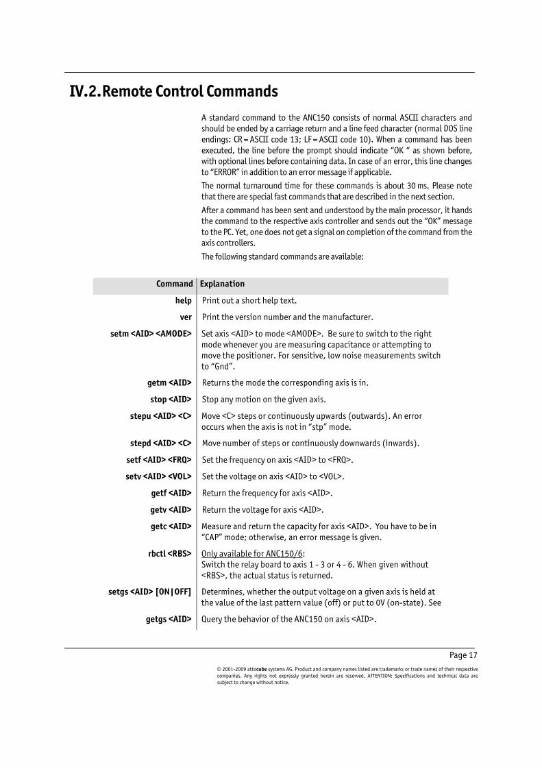
IV.2. Remote Control Commands
A standard command to the ANC150 consists of normal ASCII characters and should be ended by a carriage return and a line feed character (normal DOS line endings: CR = ASCII code 13; LF = ASCII code 10). When a command has been executed, the line before the prompt should indicate “OK “ as shown before, with optional lines before containing data. In case of an error, this line changes to “ERROR” in addition to an error message if applicable.
The normal turnaround time for these commands is about 30 ms. Please note that there are special fast commands that are described in the next section.
After a command has been sent and understood by the main processor, it hands the command to the respective axis controller and sends out the “OK” message to the PC. Yet, one does not get a signal on completion of the command from the axis controllers.
The following standard commands are available:
Command Explanation
help Print out a short help text.
ver Print the version number and the manufacturer.
setm <AID> <AMODE> Set axis <AID> to mode <AMODE>. Be sure to switch to the right mode whenever you are measuring capacitance or attempting to move the positioner. For sensitive, low noise measurements switch to “Gnd”.
getm <AID> Returns the mode the corresponding axis is in.
stop <AID> Stop any motion on the given axis.
stepu <AID> <C> Move <C> steps or continuously upwards (outwards). An error occurs when the axis is not in “stp” mode.
stepd <AID> <C> Move number of steps or continuously downwards (inwards).
setf <AID> <FRQ> Set the frequency on axis <AID> to <FRQ>.
setv <AID> <VOL> Set the voltage on axis <AID> to <VOL>.
getf <AID> Return the frequency for axis <AID>.
getv <AID> Return the voltage for axis <AID>.
getc <AID> Measure and return the capacity for axis <AID>. You have to be in “CAP” mode; otherwise, an error message is given.
rbctl <RBS> Only available for ANC150/6: Switch the relay board to axis 1 - 3 or 4 - 6. When given without <RBS>, the actual status is returned.
setgs <AID> [ON|OFF] Determines, whether the output voltage on a given axis is held at the value of the last pattern value (off) or put to 0V (on-state). See
getgs <AID> Query the behavior of the ANC150 on axis <AID>.

Page 18
setpu <AID> <PNUM> Set pattern number <PNUM> for upward movement on axis <AID>.
setpd <AID> <PNUM> Set pattern number <PNUM> for downward movement on axis <AID>.
getpu <AID> Get pattern number used for upward movement on axis <AID>.
getpd <AID> Get pattern number used for downward movement on axis <AID>
setp <PIDX> <PVAL> Set value no. <PIDX> to value <PVAL> in the temporary pattern memory.
getp <PIDX> Read value no. <PIDX> from the temporary pattern memory.
resetp Reset all patterns to factory defaults.
Valid variable values are:
Variable Name Valid values
<AID> axis id 1, 2, 3
<AMODE> axis mode ext, stp, gnd, cap
<C> run mode c (continuous run),
1, 2, … N [steps]
<FRQ> frequency 1, 2, ... 8000 [Hertz]
<VOL> voltage 0, 1, ... 70 [Volt]
<PNUM> pattern number 0, 1, … 19
<PVAL> pattern value 0, 1, … 255
<PIDX> value index 0, 1, … 255
<RBS> relay board status on, off
Note: Please note that the commands stepu and setpu are very similar. Unintentional mistaking of the two commands can result in reprogramming the pattern for the respective axis causing the positioner to move in the same direction for both commands stepu and stepd.

Page 19
© 2001-2009 attocube systems AG. Product and company names listed are trademarks or trade names of their respective companies. Any rights not expressly granted herein are reserved. ATTENTION: Specifications and technical data are subject to change without notice.
IV.3. Fast Commands
There are some special commands that are executed faster. When using a fast command, “$” needs to be sent as the first character on the command prompt. On successful completion, “+” is being sent back; “-“ in case of an error. No error message will be given. The typical turnaround time for the fast commands is about 10 ms. The following fast commands are available:
Command Explanation
$M<AXIS><MODE> Set a given axis to a certain mode.
Example:
$M1S - set axis 1 to “STP” (Run) mode.
$S<AXIS><DIR> Perform a step with a certain axis in a given direction.
Example:
$S1U - make one step upwards with axis 1
Valid variable values are:
Variable Name Valid values Comment
<AXIS> axis id 1, 2, 3
<MODE> mode E, S, G, C for Ext, Stp, Gnd, Cap
<DIR> direction U, D for Up or Down

Page 20
IV.4. LabView™ Drivers
All the commands described above are also available as LabView™ VIs. You can find them on the CD delivered with the system. There are drivers for different Labview versions available. Copy all of them to a convenient location on your disk. The following VIs are provided:
ANC150_start_communication.vi Reset the serial port with the correct settings and flush the buffers of the computer. This is a recommended start procedure for any application VI.
ANC150_communication.vi This program handles the basic communication over the serial port. A given command is written to the serial port. After certain waiting time the answer is read and interpreted. This VI calls ANC150_Errorhandler.vi.
ANC150_Errorhandler.vi The answer of the controller is scanned for error messages. If tell error is true, a message boxes is given out and the VI is stopped. If false, one can handle errors by a program. The error message is copied to error message and “ERROR” is written to the output string. If no error occurs, “OK” appears in the error string and in the output string. Any line containing values is then copied to the value string.
ANC150_getcapacity.vi Measures the capacity.
ANC150_getfrequency.vi Reads the frequency.
ANC150_getvoltage.vi Reads the voltage.
ANC150_getmode.vi Gets the mode the axis is currently in.
ANC150_setfrequency.vi Sets the frequency for a given axis.
ANC150_setvoltage.vi Sets the voltage for a given axis.
ANC150_setmode.vi Sets the mode for a given axis.
ANC150_stepd.vi Moves a given number of steps or continuously downwards.
ANC150_stepu.vi Moves a given number of steps or continuously upwards.
ANC150_stop.vi Instantly stops any action on a given axis.
ANC150_setp.vi Sets a value of the temporary pattern memory.
ANC150_getp.vi Gets a value of the temporary pattern memory.
ANC150_resetp.vi Resets all patterns to factory defaults.
ANC150_fcommand.vi Issue a fast command and give back the return code.
ANC150_move.vi A sample VI that drives one axis. It first sets the mode, then issues a number of steps and sets the mode afterwards to “gnd”.
ANC150_readcapacity.vi A sample VI to read the capacity. It first sets the mode to “cap”, then reads the capacity via ANC_getcapacity.vi and sets the mode afterwards to “gnd”.
ANC150_pattern_generator.vi A VI to generate patterns. You can select from several mathematical functions and transfer them to the ANC150. Save to and read from disk functions are implemented.

Page 21
© 2001-2009 attocube systems AG. Product and company names listed are trademarks or trade names of their respective companies. Any rights not expressly granted herein are reserved. ATTENTION: Specifications and technical data are subject to change without notice.
IV.5. Pattern Definition
The normal patterns of the ANC150 are shown in the figures below. Yet, these can be changed if needed. In this section, it is explained how to change these patterns and how to define your own pattern.
Figure 4: Signal form for downward movement (with respect to a ANPz101 positioner).
Figure 5: Signal form for upward movement.
In the ANC150, a signal is generated from 256 sequential values, with the values ranging from 0 to 255. A linear pattern for example consists of 256 small steps with increments of 1/256 multiplied by the voltage that has been set on the front panel. The time for each individual step is t= 1/256 * 1/f, with f being the chosen frequency.
There are 20 predefined patterns that can be selected from:
Pattern Memory No. Direction Curve form
0 up linear curve
1 down linear curve
2 up logarithmic curve
3 down exponential curve
4 up exponential curve
5 down logarithmic curve
6,8,10,…,18 up linear curve
7,9,11,…,19 down linear curve

Page 22
Figure 6: Sketch of the predefined patterns in the curve memory of the ANC150. Up means there is a slow rise followed by a steep fall (downwards vice versa). This
notation corresponds to the actual movement of a z-positioner connected to such a
signal.
Page 23
© 2001-2009 attocube systems AG. Product and company names listed are trademarks or trade names of their respective companies. Any rights not expressly granted herein are reserved. ATTENTION: Specifications and technical data are subject to change without notice.
IV.6. Programming New Patterns
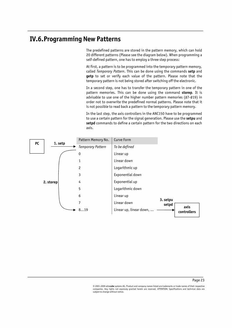
The predefined patterns are stored in the pattern memory, which can hold 20 different patterns (Please see the diagram below). When programming a self-defined pattern, one has to employ a three step process:
At first, a pattern is to be programmed into the temporary pattern memory, called Temporary Pattern. This can be done using the commands setp and getp to set or verify each value of the pattern. Please note that the temporary pattern is not being stored after switching off the electronic.
In a second step, one has to transfer the temporary pattern in one of the pattern memories. This can be done using the command storep. It is advisable to use one of the higher number pattern memories (#7-#19) in order not to overwrite the predefined normal patterns. Please note that it is not possible to read back a pattern to the temporary pattern memory.
In the last step, the axis controllers in the ANC150 have to be programmed to use a certain pattern for the signal generation. Please use the setpu and setpd commands to define a certain pattern for the two directions on each axis.
Pattern Memory No. Curve Form
Temporary Pattern To be defined
0 Linear up
1 Linear down
2 Logarithmic up
3 Exponential down
4 Exponential up
5 Logarithmic down
6 Linear up
7 Linear down
8…19 Linear up, linear down, …
1. setp PC
2. storep
3. setpu setpd
axis controllers

Page 24
IV.6.a. Resetting the Pattern Memory
To reset the entire pattern memory to factory defaults, please use the command resetp. However, this resets only the curve memory, but does not change the patterns actually used by the axis controllers. These have to be set for the individual axes using the commands setpu and setpd.
The factory default can be restored using the following commands:
> resetp
> setpu 1 0
> setpd 1 1
> setpu 2 0
> setpd 2 1
> setpu 3 0
> setpd 3 1
In conclusion, one can easily use the features of the ANC150 to accommodate for special needs. For example, one can think of a pattern being constant at a certain value to force the ANC to give out constant voltages. Also, with most of the positioners, one can reach a little better performance when setting an exponential pattern (curve no. 4) for the upward and a logarithmic pattern (curve no. 3) for downward movement.
In the next chapter, we will describe how to change the behavior of the ANC150 in such a way that there is a constant voltage being given out and the stepping patterns are performed by pulling the voltage down, not up.
IV.7. Maintaining the Voltage after a Step
Normally, after a pattern (a step) has completed, the voltage is put to 0 V to protect the piezo. This behavior can be changed in order to achieve alternative forms of stepping. To change from normal behavior to an inverted behavior (where the voltage is maintained at high level), one has to perform the following steps:
In order to change the behavior of the axes so that the voltage of the last pattern value is maintained, issue the command
> setgs <AID> off
This has to be set for each individual axis. Please note that at the moment, the ANC150 does not store this behavior, so that one has to issue these commands for each session once.
At next, one has to modify the patterns in such a way, that the last value of the pattern is always at 255, so that the high voltage can be given out.
For this, please use the ANC150_pattern_generator.vi to define a linear down pattern and change the last value (index 255) using the array control to the value 255.

Page 25
© 2001-2009 attocube systems AG. Product and company names listed are trademarks or trade names of their respective companies. Any rights not expressly granted herein are reserved. ATTENTION: Specifications and technical data are subject to change without notice.
Alternatively, one can program each value of this linear up pattern by entering these commands:
> setp 0 255
> setp 1 254
…
> setp 254 1
> setp 255 255
The last line defines the important change that is required to change the behavior. Now store this pattern e.g. to memory no. 6 using the respective function in the pattern generator or by using the command:
> storep 6
The up-pattern does not need to be changed as the last value is already defined to be 255.
Now, the new pattern is stored to memory no. 6. Define to use this pattern (e.g. pattern no. 6) for the downward direction on the axis of choice (e.g. axis no. 1) by using again the pattern generator vi or by issuing the command:
> setpd 1 6
The graph above illustrates the changes needed. Changing whether the voltage is maintained at high level or not is not sufficient. Therefore, one has to change the down pattern accordingly in order to get to the desired behavior.
Note: When the voltage is maintained at high level, changing the step voltage level will temporarily pull the voltage level to 0 V.

Page 26
IV.8. Optional TTL Input
Via the TTL input (optional), it is possible to trigger single pulses of the ANC150. The electronic has to be in “RUN” (front panel), or in “stp” mode, when the computer is connected (“CCON”).
The signal has to be connected to the 15pin connector on the backside of the ANC. The connection scheme is as follows:
Pin No. Contact Name Pin No. Contact Name
1 Axis 1 up 9 n.c. 2 Axis 1 down 10 n.c. 3 Axis 2 up 11 n.c. 4 Axis 2 down 12 n.c. 5 Axis 3 up 13 n.c. 6 Axis 3 down 14 GND 7 n.c. 15 GND 8 n.c.
Shape of the TTL input signal:
Default mode is active high (this can be switched to active low via an internal DIP-switch), meaning that a pulse is generated when the signal voltage crosses the trigger voltage in rising direction. The trigger voltage is set to 2.5 V (the low voltage should be smaller than 2.4 V and the high voltage should be higher than 2.6 V but should not exceed 5V!). The duration of the high signal level should be 3 ms minimum, with 5 ms suggested. The maximum reliable frequency is around 100 Hz, i.e. it is suggested to apply a signal for 5 ms followed by a pause of 5 ms (see Figure below).
Important: Ground needs to be set to chassis ground of the ANC in order for the TTL module to operate correctly.
Figure 7: Shape of TTL input signal.
>2.6V
<2.4V
>5ms
>5ms

Page 27
© 2001-2009 attocube systems AG. Product and company names listed are trademarks or trade names of their respective companies. Any rights not expressly granted herein are reserved. ATTENTION: Specifications and technical data are subject to change without notice.
IV.9. Firmware Upgrade
At some point, a new firmware might be available for the ANC150. The following step-by-step description explains how to load this new firmware in the Flash memory of the ANC150 and how to activate it.
1. Establish a terminal connection as described before in section IV.1.
2. Turn the ANC150 on or reset the controller with 'rst' and break into the boot procedure of the bootloader by pressing 'Ctrl-c'. Now, you are connected to the operating system of the ANC150.
3. At the 'RedBoot> ' prompt type 'load' and 'Enter'. 4. Upload the new firmware (typical 'ANC150-xxxxxx.rec') using
xmodem protocol. (Hyperterminal: Transfer -> SendFile, TeraTerm: File -> Transfer -> X-Modem -> Send)
5. When the transfer is finished, type 'fis create app' and Enter. 6. After the initialization has finished, turn the ANC150 off and on
again (after ~10s). 7. Now the controller is ready to work with the new firmware.
Figure 8: Screen of the Terminal program while performing a firmware upgrade. You can see the prompt of the bootloader, as well as the menu structure for transferring the file via xmodem protocol.

Page 28
V. Preventive Maintenance
Warning. The equipment contains no user servicable parts. There is a risk of severe electrical shock if the equipment is operated with the covers removed. Only personnel authorized by attocube systems and trained in the maintenance of this equipment should remove its covers or attempt any repairs or adjustments. Maintenance is limited to safety testing and cleaning as described in the following sections.
Note: Please note that you may loose the warranty for the ANC150 in case unauthorized persons have opened the housing or unauthorized parts or actions have been employed. This is especially true in case of fuses that have higher specifications than allowed.
V.1. Safety Testing
Safety testing in accordance with local regulations, should be performed on a regular basis, (typically annually for an instrument in daily use).
Caution. The instrument contains a power supply filter. Insulation testing of the power supply connector should be performed using a DC voltage.
V.2. Fuses
A T 0.5A/250V (T 0.8A/250V for 100 / 115 V) fuse is located on the back panel of the ANC150
Note. When replacing fuses: 1) Switch off the power and disconnect the power cord before
removing the fuse cover. 2) Always replace broken fuses with a fuse of the same rating and
type. You may loose your warranty in case wrong fuses are being used.
V.3. Cleaning
Warnings. • Disconnect the power supply before cleaning the unit.
• Never allow water to get inside the case.
• Do not saturate the unit.
• Do not use any type of abrasive pad, scouring powder, or solvent, e.g. alcohol or benzene.
The fascia may be cleaned with a soft cloth, lightly dampened with water or a mild detergent.

Page 29
© 2001-2009 attocube systems AG. Product and company names listed are trademarks or trade names of their respective companies. Any rights not expressly granted herein are reserved. ATTENTION: Specifications and technical data are subject to change without notice.
VI. Questions & Answers
Note: Any time you call for technical support, the firmware version and the serial number are essential to trouble-shoot a problem. They can be queried with the info command “ver”.
Q) The positioner is not moving properly. A) This might have several reasons. Please check that the following issues are fulfilled and not the cause of the problem:
- Please check the fuses of the ANC150. Are they ok? - Please check the fuse named FU4 on the back side of the ANC. It is
responsible for the internal 70 V power supply. In most cases this fuse blows due to a short-circuit or an overload of the ANC. Please check your settings and your circuitry on possible flaws.
- Please check that the power line has the correct voltage level. If the voltage gets too low due to too many multiple sockets, the internal voltages might fall under some certain level. Then, the controller might get unstable or not work at all.
- Is the positioner connected to the correct axis? - Is the capacitance as expected? If not, the piezo might be broken
or disconnected. - Is the positioner mounted to a base? - Is the positioner free to move? If it is blocked by external objects,
it might not be able to move. - Have you tried to vary the frequency and the voltage? Sometimes
the positioner may stick a little. - Can you measure infinite resistance? Otherwise, there might be a
short circuit within the positioner. - Try to isolate the error by exchanging the positioner with others
and changing the cabling, the electronics (axis). Is the problem within the positioner? Can you hear the sound?
- Is the cabling low-ohmic (less than 5 Ohm)? If not, the positioners step efficiency will go down or stop the positioner completely.
- Are there any cold solder points? If yes, they might cause a loose contact, especially when going to low temperatures.
Q) What happens if the polarity is inverted, i.e. if I connect the positioner the other way around? How can I check and prevent this? A) If the polarities are reversed, the direction of movement is inverted. This is also a way of checking whether a positioner is connected with the right polarity. Try to move the positioner with 15 V maximum. If the positioner moves “inward”, when the direction “outward” is wanted, then it is probably connected in the wrong way. Warning: At voltages higher than 15 - 20 V the piezo will be re-polarized in the other direction! Hence, the direction of movement is reversed and the positioner will act as if

Page 30
connected normal. However, repolarizing the positioner very often causes damage to the piezo.
Q) The positioner is moving in the opposite direction. What’s the
reason? A) Probably, the positioner is connected with the wrong polarity. See above.
Q) The positioner is moving in the same direction for both commands ‘stepu’ and ‘stepd’. What’s the cause? Please note that the commands ‘stepu’ and ‘setpu’ are very similar. Unintentional mistaking of the two commands can result in reprogramming the pattern for the respective axis causing the positioner to move in the same direction for both commands ‘stepu’ and ‘stepd’. Please correct the pattern setting using the command ‘setpu’ and ‘setpd’ for the respective axis as described in section IV of this manual.
Q) I have Hyperterminal open, but I cannot communicate with the ANC150. What’s the problem? A) Please double-check the port number and the connection parameters (especially the connection speed!). Please check your cable for compatibility as described. Please connect to the electronics and switch it on. You should see a start message similar to what is written in the respective section of this manual.
Q) Can the axis control system be controlled by GPIB interfaces? A) The electronics has a RS232 port, which can easily be programmed with simple text commands. Labview drivers and some sample VIs are supplied with the system. Currently attocube systems does not offer a GPIB interface.
Q) Is a scanning option available? A) The ANC150 can generate the signal needed to drive the positioner in "step-mode". For DC-scanning one needs an additional electronics. attocube systems offers such solutions and we would be happy to supply you with such solutions. This scanning electronics can be conveniently connected to the ANC150 using special inputs. When the electronic is switched to EXT mode, those inputs are directly feed through to the outputs.
Q) I want to reduce the heat load on the cryostat. Can I connect the positioners using resistive wires? A) No, this is important. A resistance of 10 Ohms may be enough to prevent the positioners from working, as they require high currents (at low temps about 0.5 to 1 A maximum). Alternatively, one can use superconducting wires reducing the heat transfer without increasing the resistance.

Page 31
© 2001-2009 attocube systems AG. Product and company names listed are trademarks or trade names of their respective companies. Any rights not expressly granted herein are reserved. ATTENTION: Specifications and technical data are subject to change without notice.
attocube systems AG
Königinstrasse 11a (Rgb) D-80539 München
Germany
Phone +49 89 2877 80915 Fax +49 89 2877 80919