atv310 fan kit - schneider electric
TRANSCRIPT

ATV310 Fan kit
1/3
VZ3V310D15N4, VZ3V310D22N4
NNZ69986-0011 - 2020
VZ3V310D15N4
VZ3V310D22N4
Electrical equipment should be installed, operated, serviced, and maintained only by qualified personnel. No responsibilityis assumed by Schneider Electric for any consequences arising out of the use of this product.© 2020 Schneider Electric. All Rights Reserved.
ATV310HD15N4ppATV310HD18N4pp
ATV310HD22N4pp
NNZ6998600
DANGERHAZARD OF ELECTRIC SHOCK, EXPLOSION, OR ARC FLASH• Only appropriately trained persons who are familiar with and fully understand the contents of the present manual and all other pertinent product documentation and who have received all necessary training to recognize and avoid hazards involved are authorized to work on and with this drive system.• Installation, adjustment, repair and maintenance must be performed by qualified personnel.• Verify compliance with all local and national electrical code requirements as well as all other applicable regulations with respect to grounding of all equipment.• Only use properly rated, electrically insulated tools and measuring equipment.• Do not touch unshielded components or terminals with voltage present.• Prior to performing any type of work on the drive system, block the motor shaft to prevent rotation.• Insulate both ends of unused conductors of the motor cable.• Do not short across the DC bus terminals or the DC bus capacitors or the braking resistor terminals. • Before performing work on the drive system:
- Disconnect all power, including external control power that may be present.- Place a "Do Not Turn On" label on all power switches.- Lock all power switches in the open position.- Wait 15 minutes to allow the DC bus capacitors to discharge. The DC bus LED is not an indicator of the
absence of DC bus voltage that can exceed 800 Vdc.- Verify that no other voltage is present in the drive system.
• Before applying voltage to the drive system: - Verify that the work has been completed and that the entire installation cannot cause hazards. - If the mains input terminals and the motor output terminals have been grounded and short-circuited, remove
the ground and the short circuits on the mains input terminals and the motor output terminals. - Verify proper grounding of all equipment. • Verify that all protective equipment such as covers, doors, grids is installed and/or closed.Failure to follow these instructions will result in death or serious injury.
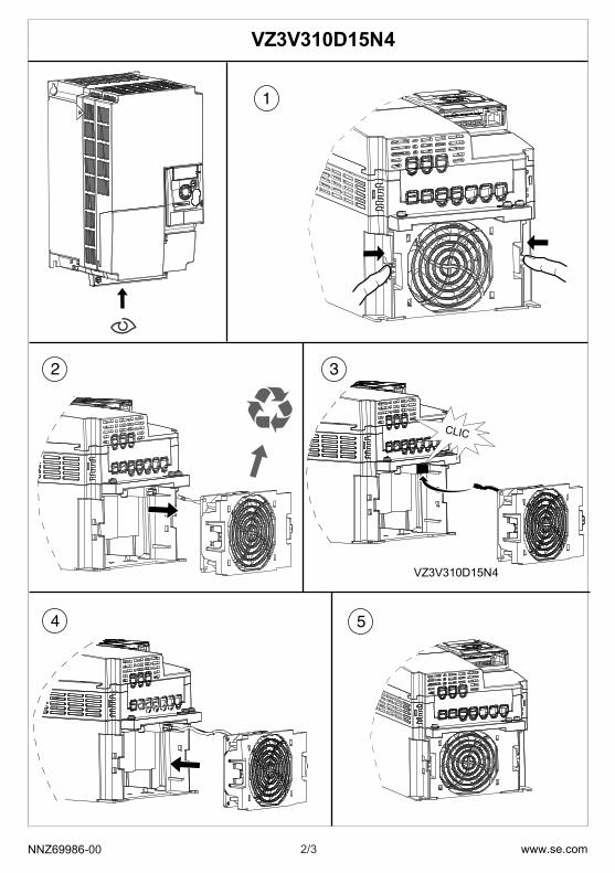
2/3NNZ69986-00 www.se.com
1
2 3
4 5
VZ3V310D15N4
VZ3V310D15N4
CLIC

3/3NNZ69986-00 www.se.com
1
2 3
4 5
VZ3V310D22N4
VZ3V310D22N4
-PH2
1.1~1.4 Nm (9.7~12.4 lbf.in)
- PH2
CLIC