atv312 canopen bbv52819 - electrocentr · bbv52819 2354235 11/2008 altivar 312 variable speed...
TRANSCRIPT
2354235 11/2008
BB
V5
28
19
www.schneider-electric.com
Altivar 312Variable speed drives for asynchronous motors
CANopen® communication manual
09/2009


BBV52819 09/2009 3
Contents
Important Information __________________________________________________________________________________________ 4Before you begin______________________________________________________________________________________________ 5Documentation structure________________________________________________________________________________________ 6Presentation _________________________________________________________________________________________________ 7Hardware setup CANopen® daisy chain - option VW3A31208 __________________________________________________________ 8Hardware setup CANopen® tap - option VW3CANTAP2 ______________________________________________________________ 12Configuration _______________________________________________________________________________________________ 17Signalling __________________________________________________________________________________________________ 18Software setup ______________________________________________________________________________________________ 19Software setup with PL7 and SyCon _____________________________________________________________________________ 22Description of the services _____________________________________________________________________________________ 31Object dictionary_____________________________________________________________________________________________ 45
Important Information
NOTICE
Read these instructions carefully, and look at the equipment to become familiar with the device before trying to install, operate, or maintainit. The following special messages may appear throughout this documentation or on the equipment to warn of potential hazards or to callattention to information that clarifies or simplifies a procedure.
PLEASE NOTEThe word "drive" as used in this manual refers to the controller portion of the adjustable speed drive as defined by NEC.
Electrical equipment should be installed, operated, serviced, and maintained only by qualified personnel. No responsibility is assumed bySchneider Electric for any consequences arising out of the use of this product.
© 2009 Schneider Electric. All Rights Reserved.
DANGERDANGER indicates an imminently hazardous situation, which, if not avoided, will result in death or serious injury.
WARNINGWARNING indicates a potentially hazardous situation, which, if not avoided, can result in death, serious injury orequipment damage.
CAUTIONCAUTION indicates a potentially hazardous situation, which, if not avoided, can result in injury or equipmentdamage.
CAUTIONCAUTION, used without the safety alert symbol, indicates a potentially hazardous situation which, if not avoided,can result in equipment damage.
The addition of this symbol to a Danger or Warning safety label indicates that an electrical hazard exists, which will result inpersonal injury if the instructions are not followed.
This is the safety alert symbol. It is used to alert you to potential personal injury hazards. Obey all safety messages that followthis symbol to avoid possible injury or death.
4 BBV52819 09/2009

Before you begin
Read and understand these instructions before performing any procedure with this drive.
DANGERHAZARD OF ELECTRIC SHOCK, EXPLOSION, OR ARC FLASH• Read and understand this manual before installing or operating the Altivar 312 drive. Installation, adjustment, repair, and
maintenance must be performed by qualified personnel.• The user is responsible for compliance with all international and national electrical code requirements with respect to grounding of
all equipment.• Many parts of this drive, including the printed circuit boards, operate at the line voltage. DO NOT TOUCH. Use only electrically
insulated tools.• DO NOT touch unshielded components or terminal strip screw connections with voltage present.• DO NOT short across terminals PA/+ and PC/– or across the DC bus capacitors.• Before servicing the drive:
- Disconnect all power, including external control power that may be present.- Place a “DO NOT TURN ON” label on all power disconnects.- Lock all power disconnects in the open position.- WAIT 15 MINUTES to allow the DC bus capacitors to discharge.- Measure the voltage of the DC bus between the PA/+ and PC/– terminals to ensure that the voltage is less than 42 Vdc.- If the DC bus capacitors do not discharge completely, contact your local Schneider Electric representative. Do not repair or
operate the drive• Install and close all covers before applying power or starting and stopping the drive.
Failure to follow these instructions will result in death or serious injury.
DANGERUNINTENDED EQUIPMENT OPERATION• Read and understand this manual before installing or operating the Altivar 312 drive.• Any changes made to the parameter settings must be performed by qualified personnel.
Failure to follow these instructions will result in death or serious injury.
WARNINGDAMAGED DRIVE EQUIPMENTDo not operate or install any drive or drive accessory that appears damaged.
Failure to follow these instructions can result in death, serious injury, or equipment damage.
WARNINGLOSS OF CONTROL• The designer of any control scheme must
- consider the potential failure modes of control paths and, for certain critical control functions, - provide a means to achieve a safe state during and after a path failure.
Examples of critical control functions are emergency stop and overtravel stop.• Separate or redundant control paths must be provided for critical control functions.• System control paths may include communication links. Consideration must be given to the implications of unanticipated
transmission delays or failures of the link.a
Failure to follow these instructions can result in death, serious injury, or equipment damage.
a. For additional information, refer to NEMA ICS 1.1 (latest edition), “Safety Guidelines for the Application, Installation, and Maintenance of Solid State Control” and to NEMA ICS 7.1 (latest edition), “Safety Standards for Construction and Guide for Selection, Installation and Operation of Adjustable-Speed Drive Systems.”
BBV52819 09/2009 5
Documentation structure
The following Altivar 312 technical documents are available on the Schneider Electric website (www.schneider-electric.com) as well as onDVD-ROM (reference VW3A8200).
Installation manualThis manual describes how to install and wire the drive.
Programming manualThis manual describes the functions, parameters and use of the drive terminal (integrated display terminal, optional graphic display terminaland optional remote terminal). The communication functions are not described in this manual, but in the manual for the bus or network used.
Simplified manualThis manual is a simplified version of the User manual. This manual is delivered with the drive.
Quick Start sheetThe Quick Start describes how to wire and configure the drive to start motor quickly and simply for simple applications. This document isdelivered with the drive.
Communication manuals: Modbus and CANopen®
These manuals describe the assembly, connection to the bus or network, signaling, diagnostics, and configuration of the communication-specific parameters.They also describe the protocol communication services.
Communication variables guideThis manual defines the drive control processes and the drive variables which can be accessed by the communication buses: Modbus,CANopen®, ...
6 BBV52819 09/2009

Presentation
The CANopen® socket on the Altivar 312 can be used for the following functions:
• Configuration• Settings• Control• Monitoring
This guide contains information on installation and describes the CANopen® services available. The "communication variables" guidedescribes the operating modes, as well as the Altivar 312 variables and parameters which can be accessed via the communication bus.
BBV52819 09/2009 7
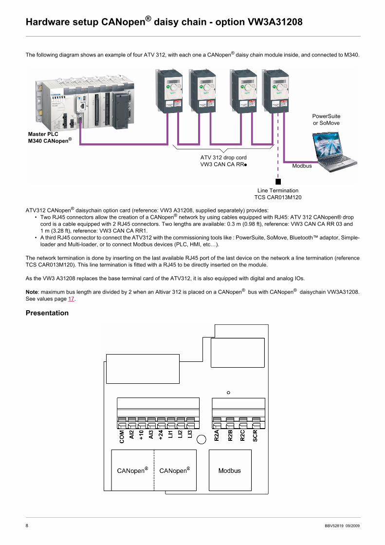
Hardware setup CANopen® daisy chain - option VW3A31208
The following diagram shows an example of four ATV 312, with each one a CANopen® daisy chain module inside, and connected to M340.
ATV312 CANopen® daisychain option card (reference: VW3 A31208, supplied separately) provides:• Two RJ45 connectors allow the creation of a CANopen® network by using cables equipped with RJ45: ATV 312 CANopen® drop
cord is a cable equipped with 2 RJ45 connectors. Two lengths are available: 0.3 m (0.98 ft), reference: VW3 CAN CA RR 03 and 1 m (3.28 ft), reference: VW3 CAN CA RR1.
• A third RJ45 connector to connect the ATV312 with the commissioning tools like : PowerSuite, SoMove, Bluetooth™ adaptor, Simple-loader and Multi-loader, or to connect Modbus devices (PLC, HMI, etc…).
The network termination is done by inserting on the last available RJ45 port of the last device on the network a line termination (referenceTCS CAR013M120). This line termination is fitted with a RJ45 to be directly inserted on the module.
As the VW3 A31208 replaces the base terminal card of the ATV312, it is also equipped with digital and analog IOs.
Note: maximum bus length are divided by 2 when an Altivar 312 is placed on a CANopen® bus with CANopen® daisychain VW3A31208.See values page 17.
Presentation
PowerSuiteor SoMove
Line TerminationTCS CAR013M120
Modbus
Master PLCM340 CANopen®
ATV 312 drop cord VW3 CAN CA RRp
8 BBV52819 09/2009
Hardware setup CANopen® daisy chain - option VW3A31208
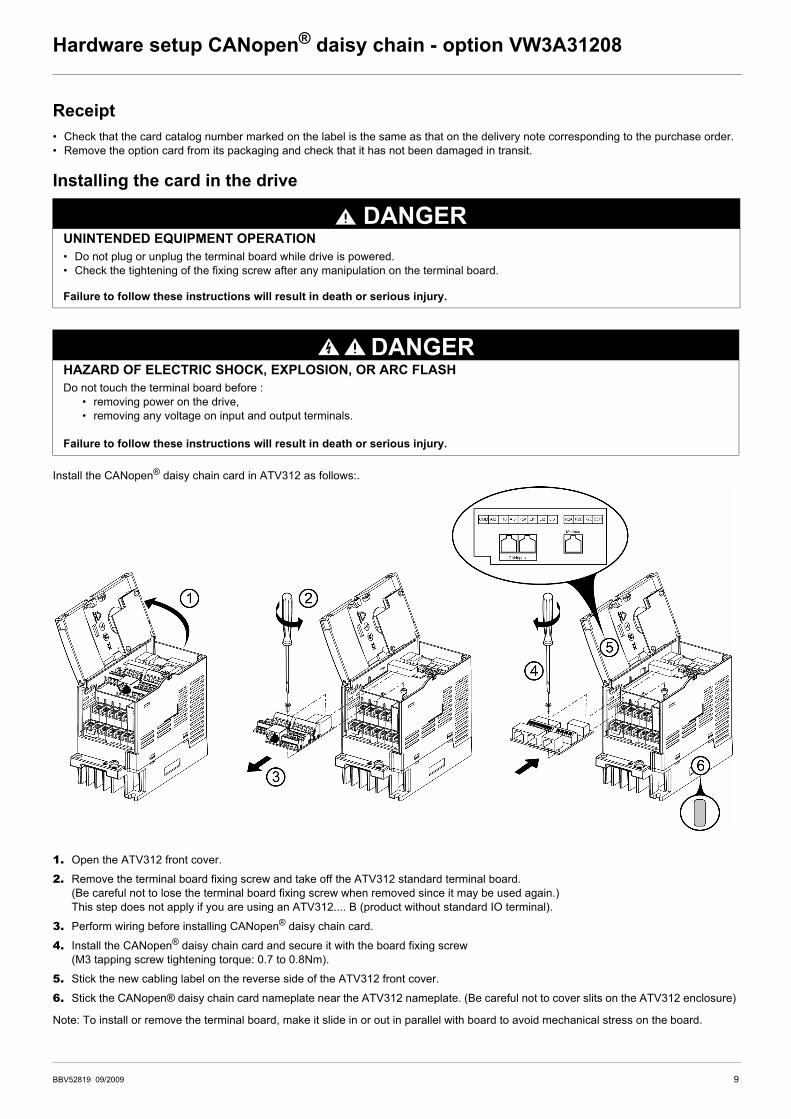
Receipt• Check that the card catalog number marked on the label is the same as that on the delivery note corresponding to the purchase order.• Remove the option card from its packaging and check that it has not been damaged in transit.
Installing the card in the drive
Install the CANopen® daisy chain card in ATV312 as follows:.
1. Open the ATV312 front cover.
2. Remove the terminal board fixing screw and take off the ATV312 standard terminal board.(Be careful not to lose the terminal board fixing screw when removed since it may be used again.) This step does not apply if you are using an ATV312.... B (product without standard IO terminal).
3. Perform wiring before installing CANopen® daisy chain card.
4. Install the CANopen® daisy chain card and secure it with the board fixing screw(M3 tapping screw tightening torque: 0.7 to 0.8Nm).
5. Stick the new cabling label on the reverse side of the ATV312 front cover.
6. Stick the CANopen® daisy chain card nameplate near the ATV312 nameplate. (Be careful not to cover slits on the ATV312 enclosure)
Note: To install or remove the terminal board, make it slide in or out in parallel with board to avoid mechanical stress on the board.
DANGERUNINTENDED EQUIPMENT OPERATION• Do not plug or unplug the terminal board while drive is powered.• Check the tightening of the fixing screw after any manipulation on the terminal board.
Failure to follow these instructions will result in death or serious injury.
DANGERHAZARD OF ELECTRIC SHOCK, EXPLOSION, OR ARC FLASHDo not touch the terminal board before :
• removing power on the drive,• removing any voltage on input and output terminals.
Failure to follow these instructions will result in death or serious injury.
BBV52819 09/2009 9

Hardware setup CANopen® daisy chain - option VW3A31208
Description of the terminals
Control terminals characteristics
Terminal Function Electrical characteristics
COM Analog I/O common 0 V
AI2 Analog voltage inputAnalog bipolar voltage input ±10 V:• impedance 30 kΩ• maximum safe voltage 30 V
10 VPower supply for the reference potentiometer (2.2 to 10 kΩ)
+10 V (+ 8% - 0):• 10 mA max• protected against short-circuits and overloads
AI3 Analog current input Analog current input X-Y mA by programming X and Y from 0 to 20 mA:impedance 250Ω
24 V Logic input power supply • + 24 V protected against short-circuits and overloads, min 19 V, max 30 V• Maximum customer current available 100 mA
LI1
Logic inputs
Programmable logic inputs:• Impedance 3.5 kΩ• + 24 V internal or 24 V external power supply (min. 19 V, max. 30 V)• Max. current: 100 mA• Max. sampling time: 4 msSource position: Positive logic State 0 if < 5 V or logic input not wired, state 1 if > 11 VSink position: Negative logic State 0 if > 19 V or logic input not wired, state 1 if < 13 VCLI position: Connection to PLC output
LI2
LI3
R2AConfigurable relay outputs 1 relay logic output, one “N/C” contact and one “N/O” contact with common point.
• Minimum switching capacity: 10 mA for 5 Vdc• Maximum switching capacity on resistive load (cos ϕ = 1 and L/R= 0 ms).
5 A for 250 Vac and 30 Vdc• Maximum switching capacity on inductive load (cos ϕ = 0.4 and L/R = 7 ms):
2 A for 250 Vac and 30 Vdc• Sampling time 8 ms• Service life: 100,000 operations at maximum switching power
R2B
R2C
SCR (Screen)CANopen® communication shield terminal.This terminal is not connected to other circuits in this board. Ground this terminal in a location separated from the ground of power line.
10 BBV52819 09/2009

Hardware setup CANopen® daisy chain - option VW3A31208
CANopen® and Modbus connectors
Wire sizes
(2)The value in bold corresponds to the minimum wire gauge to permit secureness.(3)Recommended to maximum value.
CANopen® ModbusPin RJ 45 Signal Pin RJ 45 Signal1 CAN_H 1 Not connected2 CAN_L 2 Not connected3 CAN_GND 3 Not connected4 Not connected 4 D15 Not connected 5 D06 Not connected 6 Not connected7 Not connected 7 VP (1)8 Not connected 8 Common
(1) Reserved for RS232/RS485 converter
ATV312 Control terminals Applicable wire size mm² (AWG) (2) Tightening torque N·m (lb.in) (3)
R2A, R2B, R2C 0.75 to 1 (18 to 16) 0.5 to 0.6 (4.4 to 5.3)
Other terminals 0.14 to 0.5 (26 to 20)
BBV52819 09/2009 11

Hardware setup CANopen® tap - option VW3CANTAP2
Legacy CANopen® wiring solution for ATV 312The following diagram shows an example of four ATV 312, connected to a master PLC Premium with a CANopen® master PCMCIA card(TSX CPP 110).
Various accessories are available from the catalog to facilitate the connection of these devices.
ATV 312 CANopen® tap is a passive tap (reference: VW3CANTAP2) It can be connected on a CANopen® trunk cable, using the two 5-screw terminals embedded connectors. Two RJ45 connectors allow the connection of two Altivar 312 by ATV 312 CANopen® drop cords.One RJ45 connector is designed to interface these two Altivar 312 with PowerSuite (Commissioning software tool for PC or Pocket PC).
If only one ATV 312 is connected on the tap it should be on the connector labelled "ATV1". If two ATV 312 are connected, PowerSuite canaccess the two drives in multidrop mode. The Modbus address of each drive must be different.
A remote terminal (VW3A31101) can also be connected to the "PowerSuite" connector, but in this case, only one ATV 312 drive can beconnected to the CANopen® tap (on the plug labelled "ATV1").
ATV 312 CANopen® drop cord is a cable equipped with 2 RJ45 connectors. Two lengths are available: 0.3 m (0.98 ft), reference:VW3CANCARR03) and 1 m (3.28 ft), reference: VW3CANCARR1.
Note: Only a 0.3 m (11.8 in.) drop cord can be used in a CANopen® network at a speed of 1 Mbits/s.
PowerSuite
CANopen® trunk cable
CANopen® trunk cable
ATV 312 CANopen® tap VW3 CAN TAP 2
ATV 312 drop cord VW3 CAN CA RRp
Master PLC+ TSX CPP 110
Modbus
12 BBV52819 09/2009
Hardware setup CANopen® tap - option VW3CANTAP2
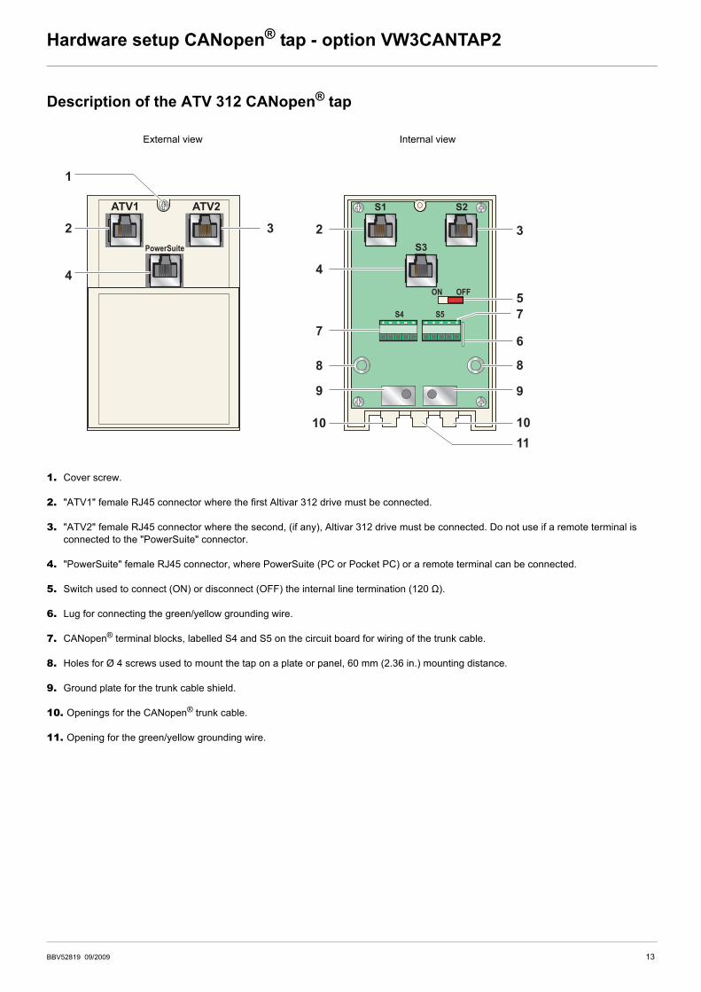
Description of the ATV 312 CANopen® tap
1. Cover screw.
2. "ATV1" female RJ45 connector where the first Altivar 312 drive must be connected.
3. "ATV2" female RJ45 connector where the second, (if any), Altivar 312 drive must be connected. Do not use if a remote terminal is connected to the "PowerSuite" connector.
4. "PowerSuite" female RJ45 connector, where PowerSuite (PC or Pocket PC) or a remote terminal can be connected.
5. Switch used to connect (ON) or disconnect (OFF) the internal line termination (120 Ω).
6. Lug for connecting the green/yellow grounding wire.
7. CANopen® terminal blocks, labelled S4 and S5 on the circuit board for wiring of the trunk cable.
8. Holes for Ø 4 screws used to mount the tap on a plate or panel, 60 mm (2.36 in.) mounting distance.
9. Ground plate for the trunk cable shield.
10. Openings for the CANopen® trunk cable.
11. Opening for the green/yellow grounding wire.
External view Internal view
1
ATV1 ATV2
PowerSuite
S1 S2
S3
ON
S4 S5
OFF
2 3
4
2
4
7
9
8
10
3
57
6
9
8
1110
BBV52819 09/2009 13

Hardware setup CANopen® tap - option VW3CANTAP2
Connecting the drive to the ATV 312 CANopen® tap Connect the cord with 2 RJ45 connectors (VW3 CAN CA RR 03 or VW3 CAN CA RR 1) to the RJ45 connector of the drive and to the "ATV1"or "ATV2" female RJ45 connector located on the ATV 312 CANopen® tap (VW3 CAN TAP 2).
If only one Altivar 312 is connected to the ATV 312 CANopen® tap the "ATV1" connector must be used.
ATV1ATV2
Power
Suite
14 BBV52819 09/2009
Hardware setup CANopen® tap - option VW3CANTAP2
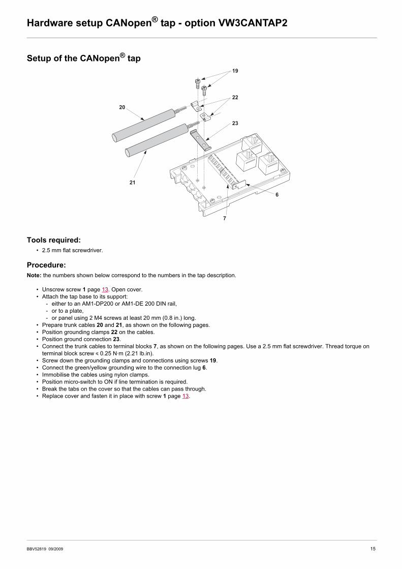
Setup of the CANopen® tap
Tools required:• 2.5 mm flat screwdriver.
Procedure: Note: the numbers shown below correspond to the numbers in the tap description.
• Unscrew screw 1 page 13. Open cover. • Attach the tap base to its support:
- either to an AM1-DP200 or AM1-DE 200 DIN rail,- or to a plate,- or panel using 2 M4 screws at least 20 mm (0.8 in.) long.
• Prepare trunk cables 20 and 21, as shown on the following pages. • Position grounding clamps 22 on the cables. • Position ground connection 23. • Connect the trunk cables to terminal blocks 7, as shown on the following pages. Use a 2.5 mm flat screwdriver. Thread torque on
terminal block screw y 0.25 N·m (2.21 lb.in).• Screw down the grounding clamps and connections using screws 19. • Connect the green/yellow grounding wire to the connection lug 6. • Immobilise the cables using nylon clamps. • Position micro-switch to ON if line termination is required. • Break the tabs on the cover so that the cables can pass through. • Replace cover and fasten it in place with screw 1 page 13.
20
19
22
23
21
7
6
BBV52819 09/2009 15
Hardware setup CANopen® tap - option VW3CANTAP2
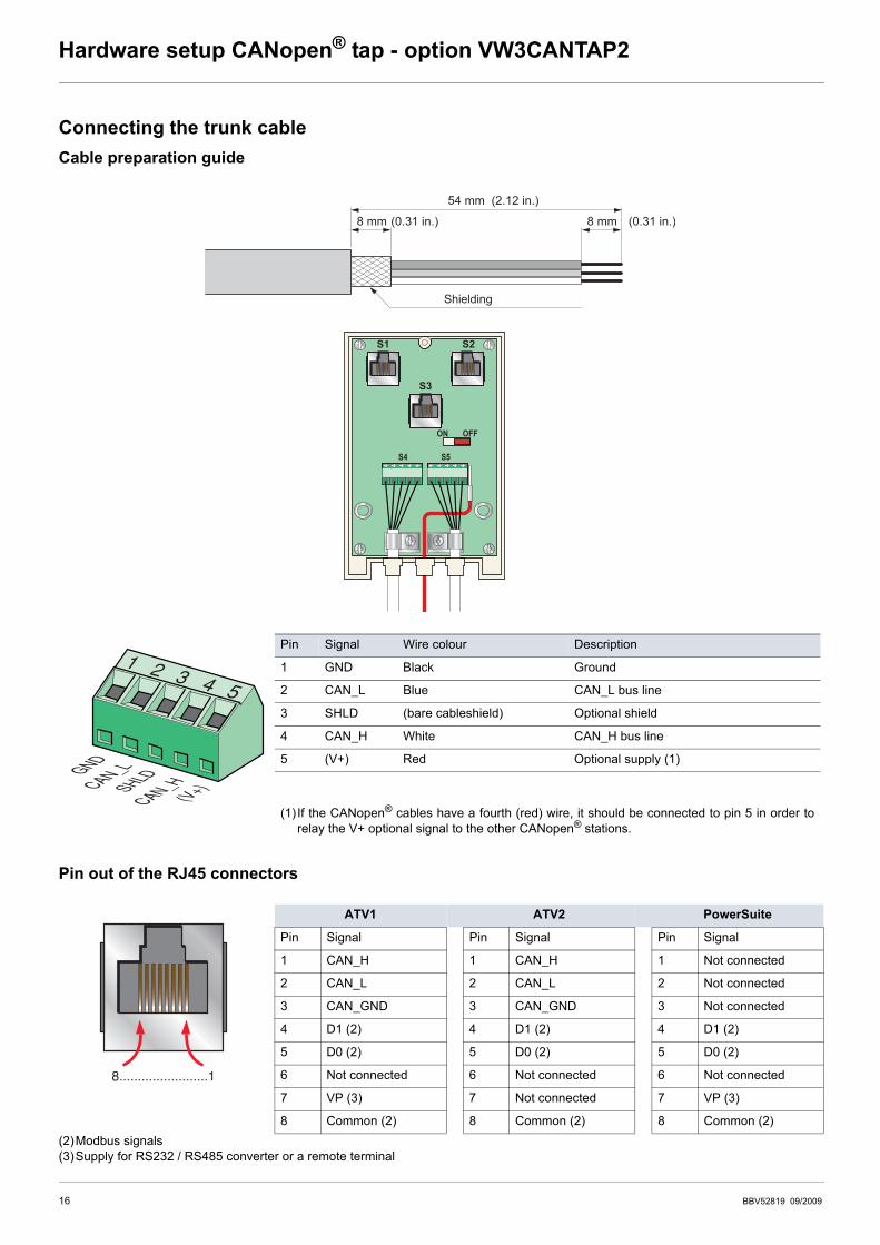
Connecting the trunk cableCable preparation guide
Pin out of the RJ45 connectors
(2)Modbus signals(3)Supply for RS232 / RS485 converter or a remote terminal
Pin Signal Wire colour Description
1 GND Black Ground
2 CAN_L Blue CAN_L bus line
3 SHLD (bare cableshield) Optional shield
4 CAN_H White CAN_H bus line
5 (V+) Red Optional supply (1)
(1) If the CANopen® cables have a fourth (red) wire, it should be connected to pin 5 in order torelay the V+ optional signal to the other CANopen® stations.
ATV1 ATV2 PowerSuite
Pin Signal Pin Signal Pin Signal
1 CAN_H 1 CAN_H 1 Not connected
2 CAN_L 2 CAN_L 2 Not connected
3 CAN_GND 3 CAN_GND 3 Not connected
4 D1 (2) 4 D1 (2) 4 D1 (2)
5 D0 (2) 5 D0 (2) 5 D0 (2)
6 Not connected 6 Not connected 6 Not connected
7 VP (3) 7 Not connected 7 VP (3)
8 Common (2) 8 Common (2) 8 Common (2)
8 mm 8 mm (0.31 in.)(0.31 in.)
54 mm (2.12 in.)
Shielding
S1 S2
S3
ON
S4 S5
OFF
1 2 3 4 5
GNDCAN_L
SHLD
CAN_H(V+)
8........................1
16 BBV52819 09/2009
Configuration
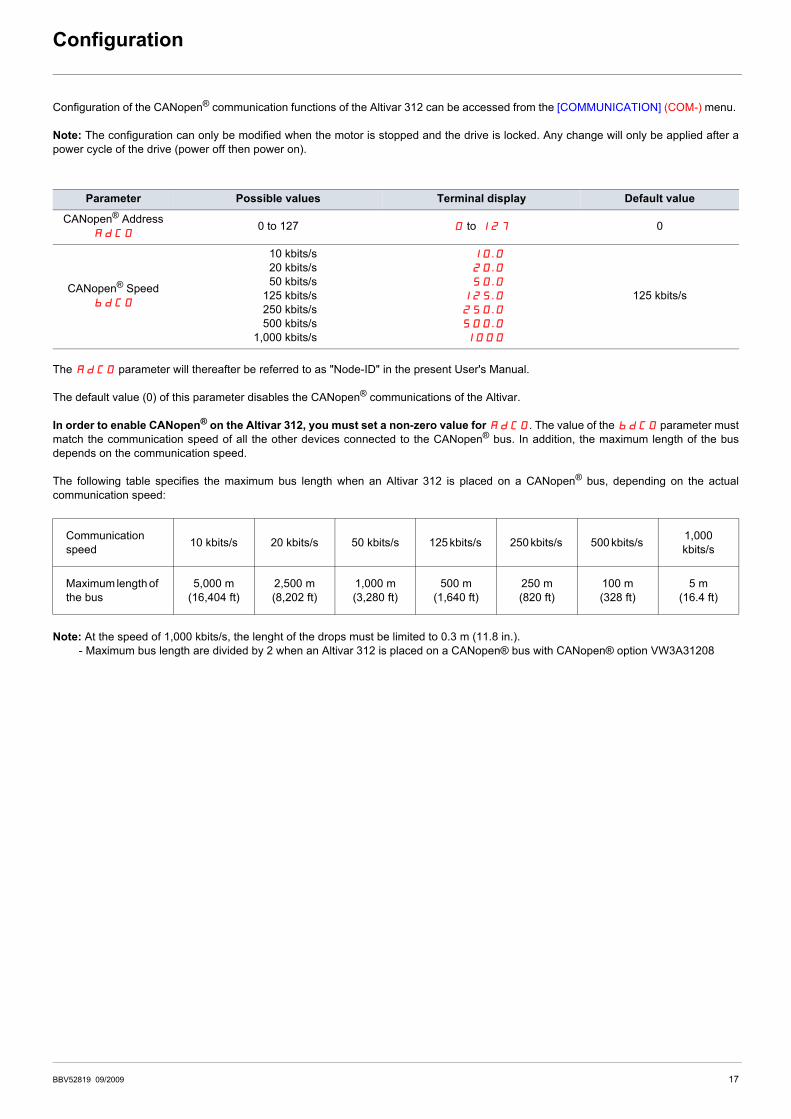
Configuration of the CANopen® communication functions of the Altivar 312 can be accessed from the [COMMUNICATION] (COM-) menu.
Note: The configuration can only be modified when the motor is stopped and the drive is locked. Any change will only be applied after apower cycle of the drive (power off then power on).
The AdC0 parameter will thereafter be referred to as "Node-ID" in the present User's Manual.
The default value (0) of this parameter disables the CANopen® communications of the Altivar.
In order to enable CANopen® on the Altivar 312, you must set a non-zero value for AdC0. The value of the bdC0 parameter mustmatch the communication speed of all the other devices connected to the CANopen® bus. In addition, the maximum length of the busdepends on the communication speed.
The following table specifies the maximum bus length when an Altivar 312 is placed on a CANopen® bus, depending on the actualcommunication speed:
Note: At the speed of 1,000 kbits/s, the lenght of the drops must be limited to 0.3 m (11.8 in.).- Maximum bus length are divided by 2 when an Altivar 312 is placed on a CANopen® bus with CANopen® option VW3A31208
Parameter Possible values Terminal display Default value
CANopen® AddressAdC0
0 to 127 0 to 127 0
CANopen® SpeedbdC0
0,010 kbits/s20 kbits/s50 kbits/s
125 kbits/s250 kbits/s500 kbits/s
1,000 kbits/s
010.020.050.0
125.0250.0500.01000
125 kbits/s
Communication speed 10 kbits/s 20 kbits/s 50 kbits/s 125 kbits/s 250 kbits/s 500 kbits/s 1,000
kbits/s
Maximum length of the bus
5,000 m(16,404 ft)
2,500 m(8,202 ft)
1,000 m(3,280 ft)
500 m(1,640 ft)
250 m(820 ft)
100 m(328 ft)
5 m(16.4 ft)
BBV52819 09/2009 17
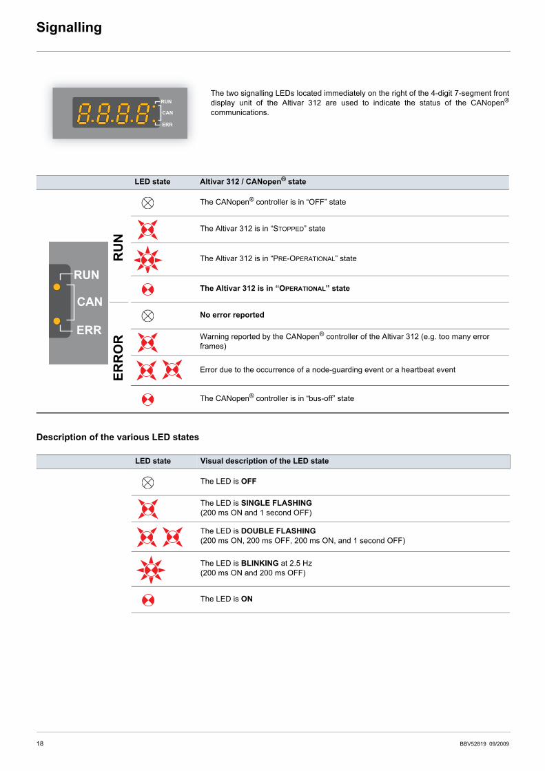
Signalling
The two signalling LEDs located immediately on the right of the 4-digit 7-segment frontdisplay unit of the Altivar 312 are used to indicate the status of the CANopen®
communications.
Description of the various LED states
LED state Altivar 312 / CANopen® state
The CANopen® controller is in “OFF” state
The Altivar 312 is in “STOPPED” state
The Altivar 312 is in “PRE-OPERATIONAL” state
The Altivar 312 is in “OPERATIONAL” state
No error reported
Warning reported by the CANopen® controller of the Altivar 312 (e.g. too many error frames)
Error due to the occurrence of a node-guarding event or a heartbeat event
The CANopen® controller is in “bus-off” state
LED state Visual description of the LED state
The LED is OFF
The LED is SINGLE FLASHING(200 ms ON and 1 second OFF)
The LED is DOUBLE FLASHING(200 ms ON, 200 ms OFF, 200 ms ON, and 1 second OFF)
The LED is BLINKING at 2.5 Hz(200 ms ON and 200 ms OFF)
The LED is ON
RU
NER
RO
R
18 BBV52819 09/2009
Software setup
Profiles Communication profile
The communication profile of Altivar 312 is based on: • CAN 2.A• The CANopen® specification (DS301 V4.02).
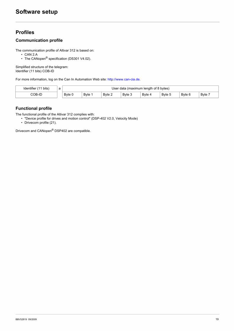
Simplified structure of the telegram: Identifier (11 bits) COB-ID
For more information, log on the Can In Automation Web site: http://www.can-cia.de.
Functional profile The functional profile of the Altivar 312 complies with:
• "Device profile for drives and motion control" (DSP-402 V2.0, Velocity Mode)• Drivecom profile (21).
Drivecom and CANopen® DSP402 are compatible.
Identifier (11 bits) a User data (maximum length of 8 bytes)
COB-ID Byte 0 Byte 1 Byte 2 Byte 3 Byte 4 Byte 5 Byte 6 Byte 7
BBV52819 09/2009 19
Software setup
Available servicesPDO (Process Data Objects)PDO telegrams are used to exchange real-time data related to the process.
PLCs refresh their inputs and outputs cyclically through PDOs (periodic variables).
The Altivar 312 features two sets of predefined PDOs:
• The first set of PDOs (PDO 1 mandatory for all modes) includes:- one received PDO, used to control (Control word "CMDD") the drive;- one transmitted PDO, used to monitor (Status word "ETAD") the drive.
PDO 1 are asynchronous and the transmitted PDO is only sent when the value of its data changes.
• The second set of PDOs (PDO 6 for velocity mode) includes:- one received PDO, used to control the drive (Control word "CMDD" and Velocity reference "LFRD"); in addition, it can be
configured to include two additional variables; Control word "CMDD" and Velocity reference "LFRD" can also be replaced with any two other variables with write access rights;
- one transmitted PDO, used to monitor the drive (Status word "ETAD" and Velocity actual value "RFRD"); in addition, it can be configured to include two additional variables; Status word "ETAD" and Velocity actual value "RFRD" can also be replaced with any two other variables.
The communication mode of PDO 6 can be set by the user, depending on their needs: asynchronous (as for PDO 1) or cyclic, based onthe reception of a synchronisation object (SYNC). A third mode is also possible, acyclic synchronous, in which the transmitted PDO is sentwhenever the value of its data changes, but only during the synchronous “window” allowed by the SYNC object.In asynchronous mode "Inhibit time" and "Event timer" can be modified.
SDO (Service Data Objects)SDO telegrams are used for configuration and setup. PLCs utilize acyclic messaging through SDOs.
The Altivar 312 manages one SDO, characterised by two COB-IDs:• one for the requests (telegrams issued by the PLC and intended to the Altivar 312);• one for the answers (telegrams sent back to the PLC by the Altivar 312)
The Altivar 312 supports segment transfer.
Other services• Default assignment of identifiers (COB-IDs), based on address;• NMT service: Start_Remote_Node (16#01), Stop_Remote_Node (16#02), Enter_Pre_Operational (16#80), Reset_Node (16#81),
Reset_Communication (16#82);• Acceptance of broadcast on COB-ID 0;• Heartbeat object;• Node guarding object;• Emergency object (EMCY);• SYNC service, for the second set of PDOs (PDO 6).
Service not available• Time stamp object (TIME)
Address on the bus (Node-ID)Node-ID = address of the drive on the CANopen® bus.
“Client” designates an entity that transmits a telegram destined to the variable speed drive (example: PLC).
20 BBV52819 09/2009
Software setup
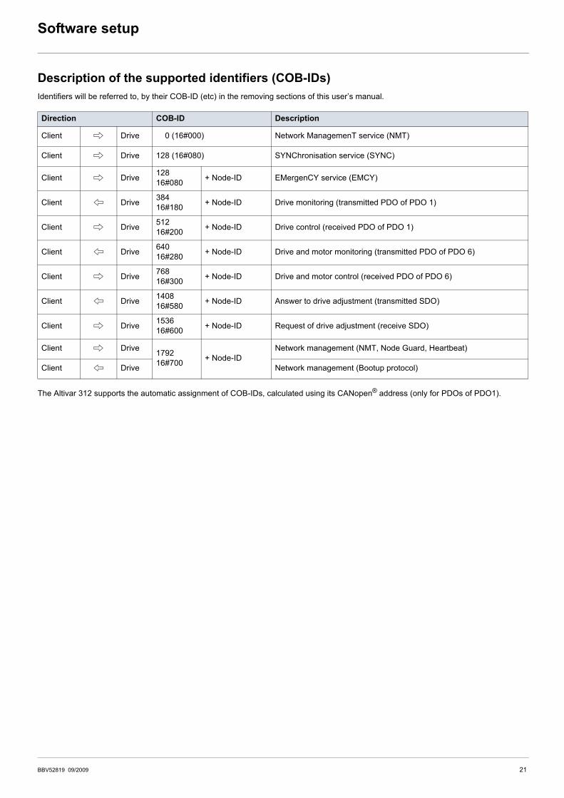
Description of the supported identifiers (COB-IDs)Identifiers will be referred to, by their COB-ID (etc) in the removing sections of this user’s manual.
The Altivar 312 supports the automatic assignment of COB-IDs, calculated using its CANopen® address (only for PDOs of PDO1).
Direction COB-ID Description
Client C Drive 000 (16#000) Network ManagemenT service (NMT)
Client C Drive 128 (16#080) SYNChronisation service (SYNC)
Client C Drive 12816#080 + Node-ID EMergenCY service (EMCY)
Client B Drive 38416#180 + Node-ID Drive monitoring (transmitted PDO of PDO 1)
Client C Drive 51216#200 + Node-ID Drive control (received PDO of PDO 1)
Client B Drive 64016#280 + Node-ID Drive and motor monitoring (transmitted PDO of PDO 6)
Client C Drive 76816#300 + Node-ID Drive and motor control (received PDO of PDO 6)
Client B Drive 140816#580 + Node-ID Answer to drive adjustment (transmitted SDO)
Client C Drive 153616#600 + Node-ID Request of drive adjustment (receive SDO)
Client C Drive 179216#700 + Node-ID
Network management (NMT, Node Guard, Heartbeat)
Client B Drive Network management (Bootup protocol)
BBV52819 09/2009 21
Software setup with PL7 and SyCon
Requirements and CANopen® architecture The following chapters describe the steps in PL7 PRO (version PL7 pro 4.5 Sycon 2.9) and SyCon (version V3.0) which you will need togo through so that the Altivar 312 is correctly recognised by the CANopen® master PLC. The software versions used here are: PL7 PROV4.3 and SyCon V2.8.
The CANopen® bus which is described in the following chapters only includes one CANopen® master (TSX 57353 V5.1 Premium PLC +TSX CPP 110 CANopen® master PCMCIA card) and one slave (Altivar 312). So you will need to adapt the addressing of the inputs andoutputs shown below (%IW and %QW) according to any other slaves on the CANopen® bus which you need to configure.
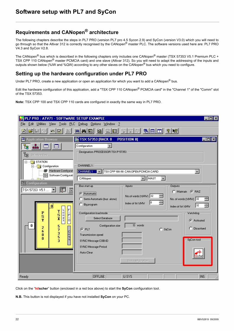
Setting up the hardware configuration under PL7 PRO Under PL7 PRO, create a new application or open an application for which you want to add a CANopen® bus.
Edit the hardware configuration of this application, add a "TSX CPP 110 CANopen® PCMCIA card" in the "Channel 1" of the "Comm" slotof the TSX 57353.
Note: TSX CPP 100 and TSX CPP 110 cards are configured in exactly the same way in PL7 PRO.
Click on the “hilscher” button (enclosed in a red box above) to start the SyCon configuration tool.
N.B. This button is not displayed if you have not installed SyCon on your PC.
22 BBV52819 09/2009
Software setup with PL7 and SyCon
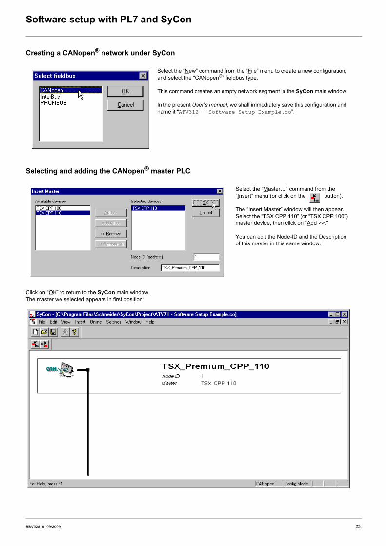
Creating a CANopen® network under SyCon
Selecting and adding the CANopen® master PLC
Click on “OK” to return to the SyCon main window.The master we selected appears in first position:
Select the “New” command from the “File” menu to create a new configuration, and select the “CANopen®” fieldbus type.
This command creates an empty network segment in the SyCon main window.
In the present User’s manual, we shall immediately save this configuration and name it “ATV312 - Software Setup Example.co”.
Select the “Master…” command from the “Insert” menu (or click on the button).
The “Insert Master” window will then appear. Select the “TSX CPP 110” (or “TSX CPP 100”) master device, then click on “Add >>.”
You can edit the Node-ID and the Description of this master in this same window.
BBV52819 09/2009 23
Software setup with PL7 and SyCon
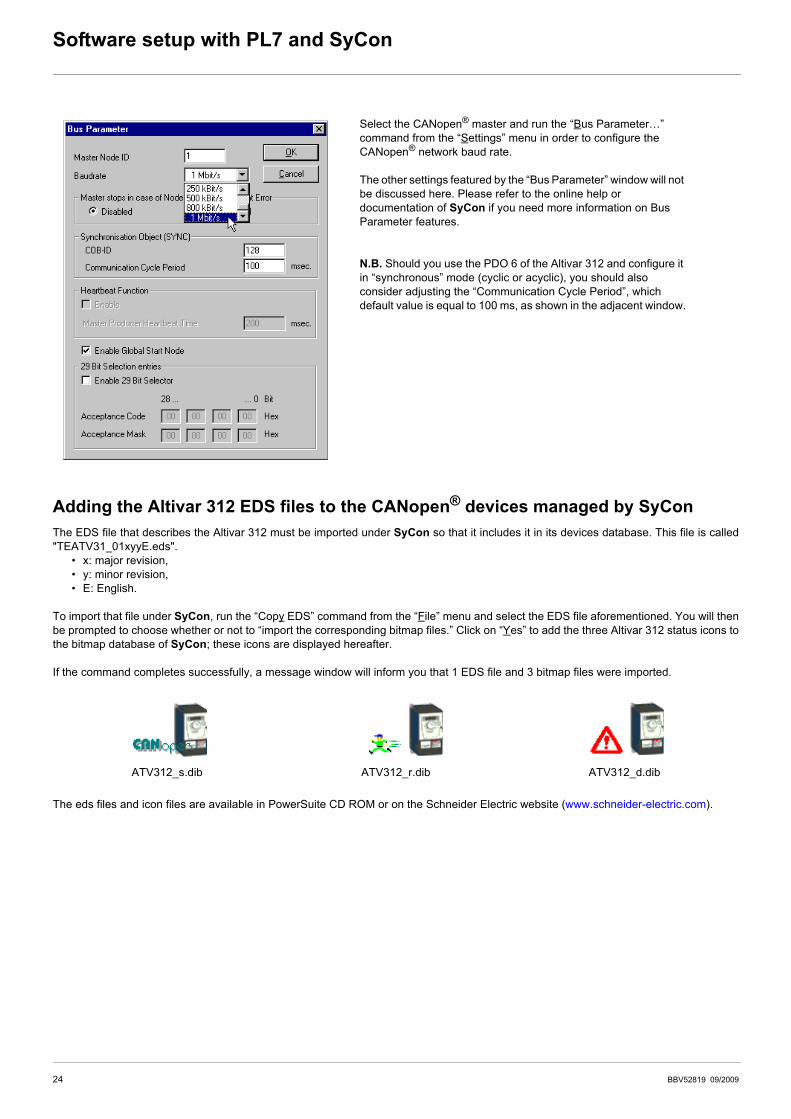
Adding the Altivar 312 EDS files to the CANopen® devices managed by SyConThe EDS file that describes the Altivar 312 must be imported under SyCon so that it includes it in its devices database. This file is called"TEATV31_01xyyE.eds".
• x: major revision,• y: minor revision,• E: English.
To import that file under SyCon, run the “Copy EDS” command from the “File” menu and select the EDS file aforementioned. You will thenbe prompted to choose whether or not to “import the corresponding bitmap files.” Click on “Yes” to add the three Altivar 312 status icons tothe bitmap database of SyCon; these icons are displayed hereafter.
If the command completes successfully, a message window will inform you that 1 EDS file and 3 bitmap files were imported.
The eds files and icon files are available in PowerSuite CD ROM or on the Schneider Electric website (www.schneider-electric.com).
Select the CANopen® master and run the “Bus Parameter…” command from the “Settings” menu in order to configure the CANopen® network baud rate.
The other settings featured by the “Bus Parameter” window will not be discussed here. Please refer to the online help or documentation of SyCon if you need more information on Bus Parameter features.
N.B. Should you use the PDO 6 of the Altivar 312 and configure it in “synchronous” mode (cyclic or acyclic), you should also consider adjusting the “Communication Cycle Period”, which default value is equal to 100 ms, as shown in the adjacent window.
ATV312_s.dib ATV312_r.dib ATV312_d.dib
24 BBV52819 09/2009
Software setup with PL7 and SyCon
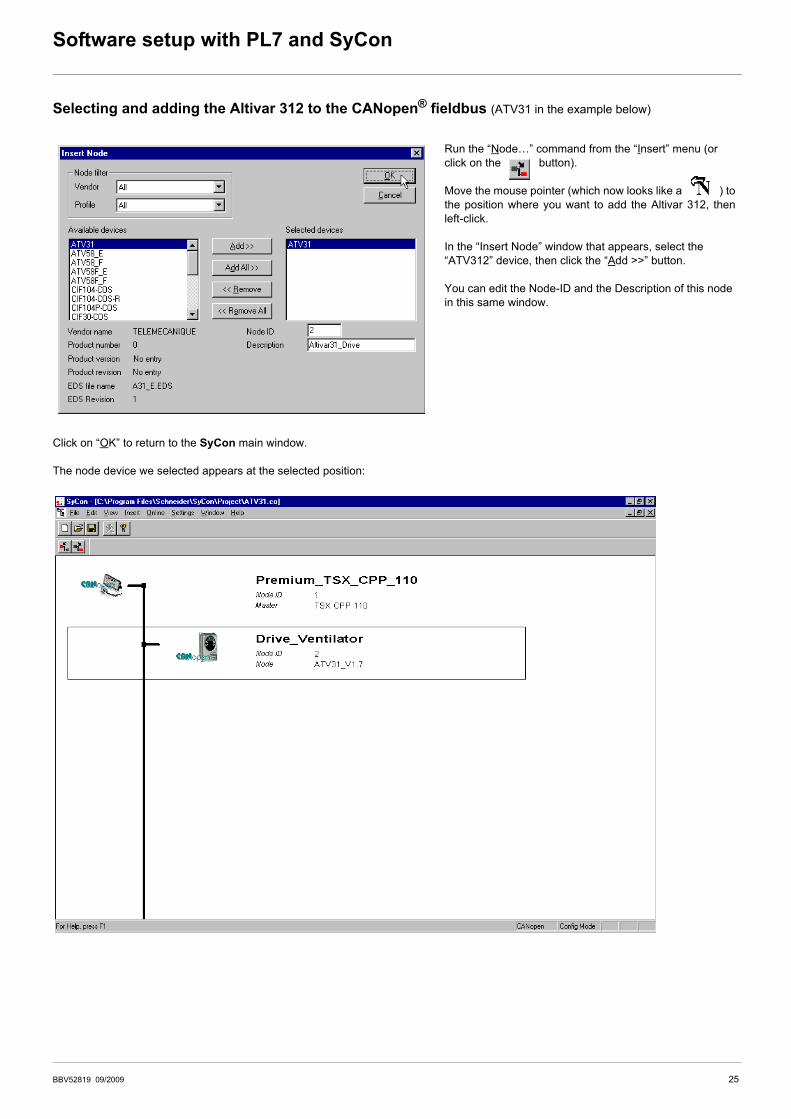
Selecting and adding the Altivar 312 to the CANopen® fieldbus (ATV31 in the example below)
Click on “OK” to return to the SyCon main window.
The node device we selected appears at the selected position:
Run the “Node…” command from the “Insert” menu (or click on the button).
Move the mouse pointer (which now looks like a ) tothe position where you want to add the Altivar 312, thenleft-click.
In the “Insert Node” window that appears, select the “ATV312” device, then click the “Add >>” button.
You can edit the Node-ID and the Description of this node in this same window.
BBV52819 09/2009 25
Software setup with PL7 and SyCon
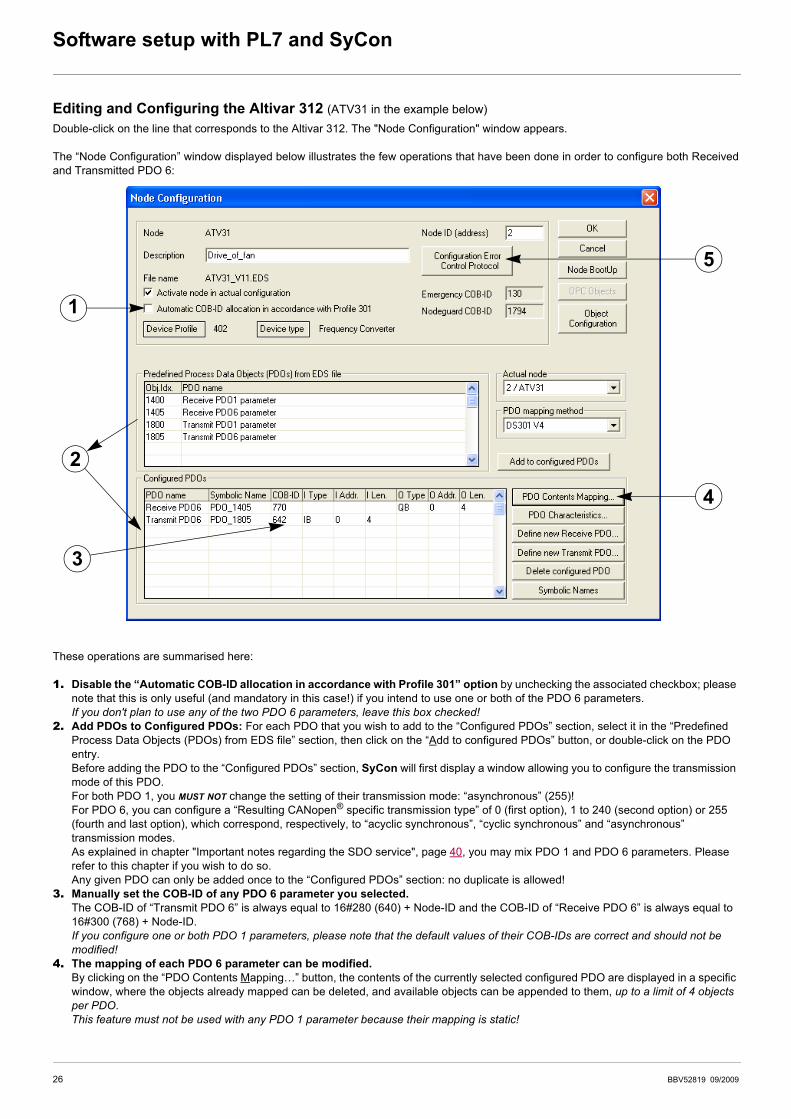
Editing and Configuring the Altivar 312 (ATV31 in the example below)Double-click on the line that corresponds to the Altivar 312. The "Node Configuration" window appears.
The “Node Configuration” window displayed below illustrates the few operations that have been done in order to configure both Receivedand Transmitted PDO 6:
These operations are summarised here:
1. Disable the “Automatic COB-ID allocation in accordance with Profile 301” option by unchecking the associated checkbox; please note that this is only useful (and mandatory in this case!) if you intend to use one or both of the PDO 6 parameters.If you don't plan to use any of the two PDO 6 parameters, leave this box checked!
2. Add PDOs to Configured PDOs: For each PDO that you wish to add to the “Configured PDOs” section, select it in the “Predefined Process Data Objects (PDOs) from EDS file” section, then click on the “Add to configured PDOs” button, or double-click on the PDO entry.Before adding the PDO to the “Configured PDOs” section, SyCon will first display a window allowing you to configure the transmission mode of this PDO.For both PDO 1, you MUST NOT change the setting of their transmission mode: “asynchronous” (255)!For PDO 6, you can configure a “Resulting CANopen® specific transmission type” of 0 (first option), 1 to 240 (second option) or 255 (fourth and last option), which correspond, respectively, to “acyclic synchronous”, “cyclic synchronous” and “asynchronous” transmission modes.As explained in chapter "Important notes regarding the SDO service", page 40, you may mix PDO 1 and PDO 6 parameters. Please refer to this chapter if you wish to do so.Any given PDO can only be added once to the “Configured PDOs” section: no duplicate is allowed!
3. Manually set the COB-ID of any PDO 6 parameter you selected.The COB-ID of “Transmit PDO 6” is always equal to 16#280 (640) + Node-ID and the COB-ID of “Receive PDO 6” is always equal to 16#300 (768) + Node-ID. If you configure one or both PDO 1 parameters, please note that the default values of their COB-IDs are correct and should not be modified!
4. The mapping of each PDO 6 parameter can be modified.By clicking on the “PDO Contents Mapping…” button, the contents of the currently selected configured PDO are displayed in a specific window, where the objects already mapped can be deleted, and available objects can be appended to them, up to a limit of 4 objects per PDO.This feature must not be used with any PDO 1 parameter because their mapping is static!
1
2
3
4
5
26 BBV52819 09/2009
Software setup with PL7 and SyCon
5. Configure the Error Control Protocol of the Altivar 312.By clicking on the “Configuration Error Control Protocol” button, you will be allowed to choose which control protocol to apply to the Altivar 312: “Node Guarding Protocol” or “Heartbeat Protocol.”
- Node Guarding Protocol: If this protocol is selected, the two parameters “Guard Time” and “Life Time Factor” are used to generate a “Life Time” duration. Please refer to chapter Node guarding protocol, page 42, for more details on this topic.e.g. in our example, we configure a “Guard Time” of 500 ms and a “Life Time Factor” or 4, thus configuring a “Life Time” or 4 × 500 ms = 2 seconds.
- Heartbeat Protocol: If this protocol is selected, the master's parameter “Master Guarding Time of Node” (16#1016: 16#xx) must be greater than the node's parameter “Node Heartbeat Producer Time” (16#1017: 16#00). If the “Master Guarding Time of Node” is set to 0 for the currently configured node, the master will not check the fieldbus activity of this node.
N.B. If you wish to use the Heartbeat Protocol with your CANopen® master, you should first enable its “Heartbeat Function” in the “Bus Parameter” window (see chapter Creating a CANopen® network under SyCon, page 23). Of course, the CANopen® master must support this protocol, which is the case of the CANopen® master used here (TSX CPP 110). The TSX CPP 100 CANopen® master PCMCIA card is an example of CANopen® master that does not support this protocol.
In addition, the “Node Heartbeat Consumer List” section allows you to configure the Altivar 312 to check another station (made distinct by its Node-ID) on the bus. Each station is named and its “Producer Time (msec.)” is recalled for convenience. By checking a box in the “Active” column, the corresponding “Node-ID” will be periodically checked by the Altivar 312; in this case, the corresponding “ConsumerTime (msec.)” must be greater than the “Producer Time (msec.).”
Saving and opening the CANopen® fieldbus configuration under PL7 PROSave the CANopen® configuration and give it a name (“Save” or “Save As…” command from the “File” menu). This configuration is savedin a “.co” file.
In the window of PL7 PRO displayed in chapter "Setting up the hardware configuration under PL7 PRO", page 22, click on the “SelectDatabase” button and select the previously saved file (e.g. “C:\Program Files\Schneider\SyCon\Project\ATV312 - Software SetupExample.co”). Once you have validated your choice, the “Configuration Loading Mode” section will be updated.
You will need to do this, for example, if you only use the two PDOs of PDO 6, as you will then have to disable the two PDOs of PDO 1.Example: The following PL7 sample disables the received PDO 1 of the Altivar 312 located at address 4:
Note Sycon V2.8 does not disable automatically PDO1, it must be done by the application program PL7.
If you wish to disable the transmitted PDO and/or the received PDO of PDO 1, you must do so in the PL7 application,using the SDO service in order to set the 31 of the “COB-ID used by PDO” of the corresponding “Receive/TransmitPDO1 parameter” object (see below). This will mark the PDO as being “not valid.”However, you must not modify the other 31 bits of the COB-ID!
Index Sub-index Description Enabled PDO Disabled PDO
16#1400 16#01 COB-ID of the received PDO 1 16#00000200 + Node-ID 16#80000200 + Node-ID
16#1800 16#01 COB-ID of the transmitted PDO 1 16#00000180 + Node-ID 16#80000180 + Node-ID
%MD1000:=16#80000184;(* Data to Send = Inhibition of the PDO *)%MW500:=16#1400;(* Logical Address - Index in %MD500 LSB *)%MW501:=16#0001;(* Logical Address - Sub-Index in %MD500 MSB *)%MW22:=50;(* Timeout = 50 x 10 ms = 500 ms *)%MW23:=4;(* Data length = 4 bytes *)(* SENDS the SDO WRITE command *)WRITE_VAR(ADR#0.1.SYS,'SDO',%MD500,4,%MW1000:2,%MW20:4);
BBV52819 09/2009 27

Software setup with PL7 and SyCon
You may also configure various options available on the CANopen® master:
Option Default Value Possible Values
(Task) MAST MAST or FAST
Used to select the type of system task that will steer the CANopen® network.N.B. The PL7 PRO software application is also subdivided into a “Mast Task” and a “Fast Task.”
Bus bootup Automatic Automatic, semi-auto. or by program
Fieldbus behaviour when the CANopen® master starts up.
Inputs %MW0 to %MW31 (Number of %MW) + (First %MW)
Number of %MW words and index of the first %MW word of the master PLC on which the input data from the TSX CPP 110 CANopen® master PCMCIA card will be mapped. Please consult the documentation of your CANopen® master and that of your master PLC in order to determine the maximum number of words that may be allocated to input words.Allocating more words than what is needed is useless. On the other hand, allocating the lowest possible size is not recommended, as the fieldbus configuration may be subject to changes, depending on the future needs of your application.The Altivar 312 may require up to 10 bytes (5 words) of input data, but this input size can only be reached by combining the “Transmit PDO” of both PDOs: 2 bytes for PDO 1 and up to 8 bytes for PDO 6 (with a default size of 4 bytes).e.g. In our example, we reduce the number of %MW input words to 2 because the only CANopen® inputs are those of the default mapping of the “Transmit PDO 6” (“I Len.” of 4 IB, as indicated under SyCon). The first input word remains %MW0. Thus, our CANopen® input words are %MW0 and %MW1.
Outputs %MW32 to %MW63 (Number of %MW) + (First %MW)
The description of the “Inputs” given above holds true here, but is related to the output words of the master PLC and to the output data of the TSX CPP 110 CANopen® master PCMCIA card.The Altivar 312 may require up to 10 bytes (5 words) of output data, but this output size can only be reached by combining the “Receive PDO” of both PDOs: 2 bytes for PDO 1 and up to 8 bytes for PDO 6 (with a default size of 4 bytes).e.g. In our example, we reduce the number of %MW output words to 2 because the only CANopen® outputs are those of the default mapping of the “Receive PDO 6” (“O Len.” of 4 QB, as indicated under SyCon). In addition, we allocate these output words so that they are placed just behind the input words: the first output word is %MW2. Thus, our CANopen® output words are %MW2 and %MW3.
Outputs Reset Hold or Reset
Determines whether the CANopen® outputs words are held or reset to zero when the associated task (see above) is stopped, because such a halt does not cause the TSX CPP 110 card to stop.
Watchdog Enabled Enabled or Disabled
If this option is enabled, the CANopen® watchdog of the TSX CPP 110 CANopen® master PCMCIA card will be triggered as soon as the card becomes unable to properly manage the CANopen® bus. At the same time, all CANopen® outputs words will be reset to 0.
Configuration Loading Mode PL7 PL7 or SyCon
PL7: The configuration of the CANopen® bus is downloaded as part of the PL7 application software to the target master PLC. If there's not enough memory left in your application for this configuration, PL7 will prohibit this mode!SyCon: The configuration of the CANopen® bus is considered as being already loaded into the PCMCIA card, thus assuming it was downloaded using SyCon. PL7 PRO only checks that the card configuration is identical to the contents of the “.co” file you selected, to aid in preventing any configuration mishap. However, any modification to the bus parameters will have to be performed under SyCon.
28 BBV52819 09/2009
Software setup with PL7 and SyCon
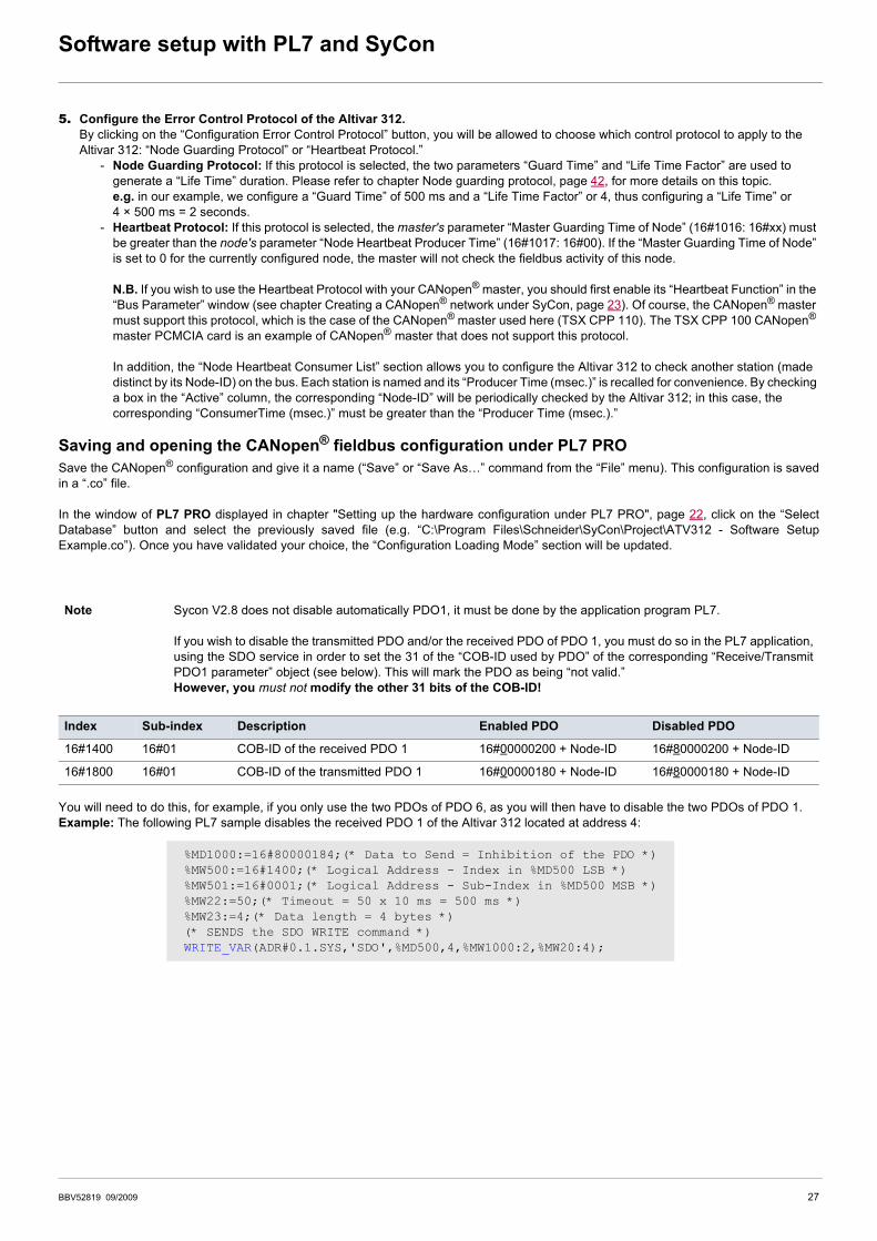
Reviewing the inputs and outputs of the CANopen® masterUsing the information located in the selected “.co” file, PL7 PRO establishes a direct correspondence between the data of each CANopen®
node and its equivalent %MW input and output words.
N.B. These allocations are only valid if the Altivar 312 is the only slave on the CANopen® bus and you do use the two PDOs of PDO 6 withtheir default mapping. If you configure other slaves on the same fieldbus, or if you alter the PDO configuration of the Altivar 312, thepreviously described input and output words allocation would be different. Should this happen, SyCon features a command that allows youto view the entire set of inputs and outputs: execute the “Address Table…” command of the “View” menu in order to do so.
The correspondence between the configured PDOs of the Altivar 312 and the PLC inputs and outputs is given in the following table:
To review the Altivar 312 I/O, click on the “Bus configuration” button. This will reveal the “CANopen® bus configuration” window, displayed here.
Selecting the “ATV312” CANopen® slave (ATV31 in the example below) (Addr. 0002) will display the input and output words configured for this sole node.
Here, on the right, explicit symbols have been assigned beforehand to the %MW0 through %MW3 words so that you can figure how these words have been linked to the PDOs mapped under SyCon.
Note: Please note that SyCon displays byte addresses and byte sizes (“IB” inputs and “QB” outputs). You should always consider that these bytes are aligned on word addresses. Hence, a 1-byte object mapped into a configured PDO will actually take up a full word: the 1-byte object will be allocated to the MSB byte of this word, and its LSB byte becomes a “spare” byte.
PDO Type SyCon I/O PL7 PRO I/O Description of the mapped object
Transmit PDO 6 InputsIB0 - IB1 %MW0 Status word "ETA"
IB2 - IB3 %MW1 Velocity actual value "RFRD"
Receive PDO 6 OutputsQB0 - QB1 %MW2 Control word "CMD"
QB2 - QB3 %MW3 Velocity Setpoint "LFRD"
BBV52819 09/2009 29
Software setup with PL7 and SyCon
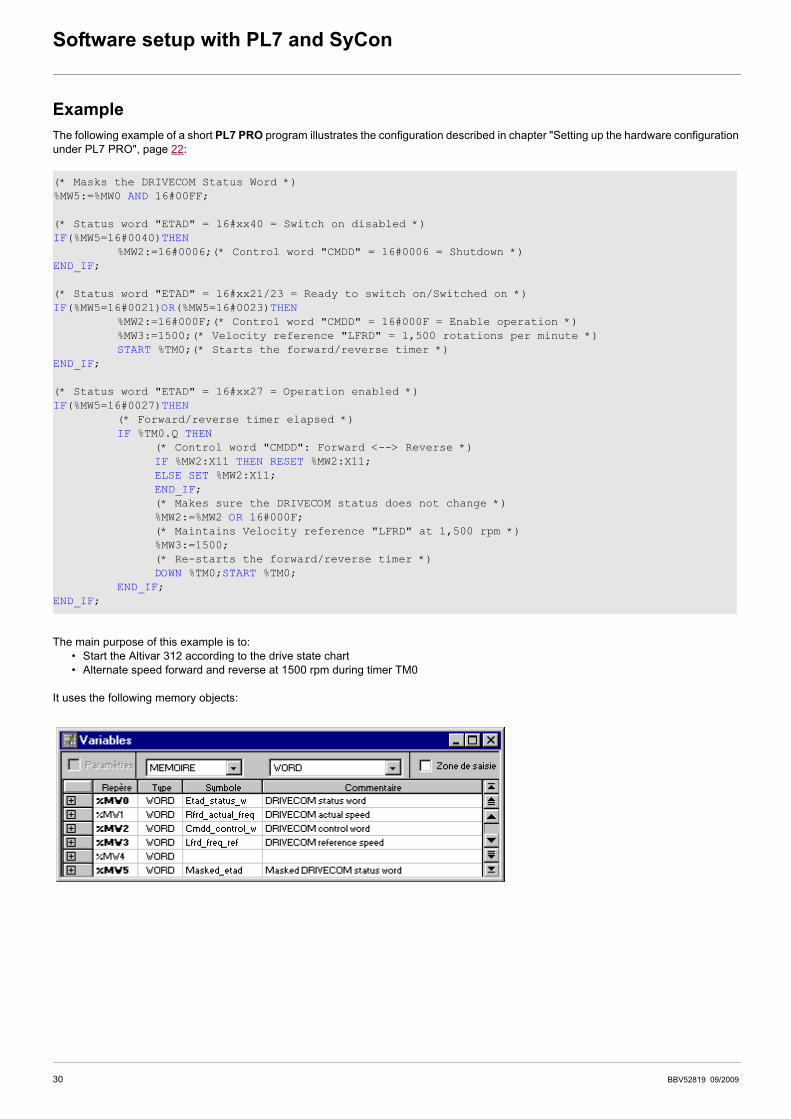
ExampleThe following example of a short PL7 PRO program illustrates the configuration described in chapter "Setting up the hardware configurationunder PL7 PRO", page 22:
The main purpose of this example is to: • Start the Altivar 312 according to the drive state chart• Alternate speed forward and reverse at 1500 rpm during timer TM0
It uses the following memory objects:
(* Masks the DRIVECOM Status Word *)%MW5:=%MW0 AND 16#00FF;
(* Status word "ETAD" = 16#xx40 = Switch on disabled *)IF(%MW5=16#0040)THEN
%MW2:=16#0006;(* Control word "CMDD" = 16#0006 = Shutdown *)END_IF;
(* Status word "ETAD" = 16#xx21/23 = Ready to switch on/Switched on *)IF(%MW5=16#0021)OR(%MW5=16#0023)THEN
%MW2:=16#000F;(* Control word "CMDD" = 16#000F = Enable operation *)%MW3:=1500;(* Velocity reference "LFRD" = 1,500 rotations per minute *)START %TM0;(* Starts the forward/reverse timer *)
END_IF;
(* Status word "ETAD" = 16#xx27 = Operation enabled *)IF(%MW5=16#0027)THEN
(* Forward/reverse timer elapsed *)IF %TM0.Q THEN
(* Control word "CMDD": Forward <--> Reverse *)IF %MW2:X11 THEN RESET %MW2:X11;ELSE SET %MW2:X11;END_IF;(* Makes sure the DRIVECOM status does not change *)%MW2:=%MW2 OR 16#000F;(* Maintains Velocity reference "LFRD" at 1,500 rpm *)%MW3:=1500;(* Re-starts the forward/reverse timer *)DOWN %TM0;START %TM0;
END_IF;END_IF;
30 BBV52819 09/2009
Description of the services
This chapter describes the various CANopen® services of the drive, listed in accordance with their increasing COB-IDs.
Any data whose length exceeds one byte is set LSB first and MSB last in a CANopen® frame.
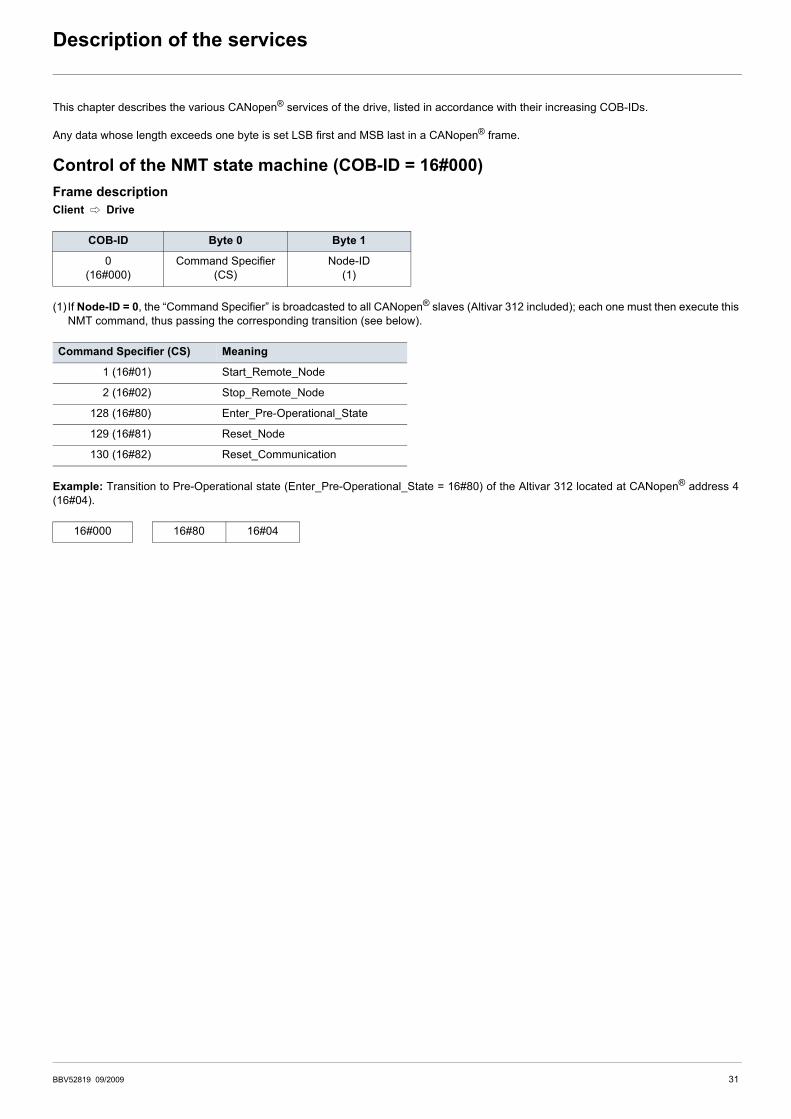
Control of the NMT state machine (COB-ID = 16#000)Frame descriptionClient C Drive
(1) If Node-ID = 0, the “Command Specifier” is broadcasted to all CANopen® slaves (Altivar 312 included); each one must then execute thisNMT command, thus passing the corresponding transition (see below).
Example: Transition to Pre-Operational state (Enter_Pre-Operational_State = 16#80) of the Altivar 312 located at CANopen® address 4(16#04).
COB-ID Byte 0 Byte 1
0(16#000)
Command Specifier (CS)
Node-ID(1)
Command Specifier (CS) Meaning
001 (16#01) Start_Remote_Node
002 (16#02) Stop_Remote_Node
128 (16#80) Enter_Pre-Operational_State
129 (16#81) Reset_Node
130 (16#82) Reset_Communication
16#000 16#80 16#04
BBV52819 09/2009 31
Description of the services
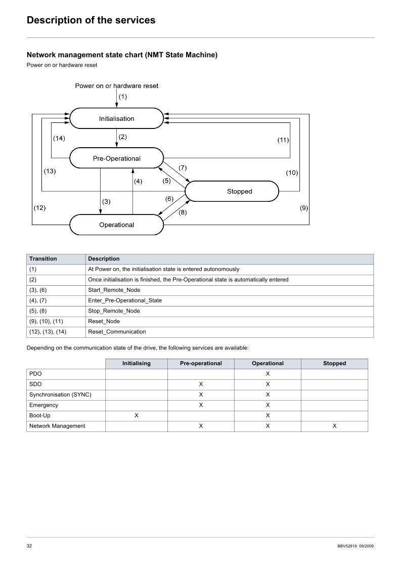
Network management state chart (NMT State Machine)Power on or hardware reset
Depending on the communication state of the drive, the following services are available:
Transition Description
(1) At Power on, the initialisation state is entered autonomously
(2) Once initialisation is finished, the Pre-Operational state is automatically entered
(3), (6) Start_Remote_Node
(4), (7) Enter_Pre-Operational_State
(5), (8) Stop_Remote_Node
(9), (10), (11) Reset_Node
(12), (13), (14) Reset_Communication
Initialising Pre-operational Operational Stopped
PDO X
SDO X X
Synchronisation (SYNC) X X
Emergency X X
Boot-Up X X
Network Management X X X
32 BBV52819 09/2009

Description of the services
Synchronisation object - SYNC (COB-ID = 16#080)Client C Drive
The SYNC object is cyclically emitted by the CANopen® master.It does not include any data, hence limiting its frame to its sole COB-ID.
The main purpose of this object is to allow to use the synchronous communication modes of the CANopen® slaves. Thus, in the case ofthe Altivar 312, the PDO 6, if used, can be set on one of the possible synchronously cyclic or acyclic communication modes.
Emergency Object - EMCY (COB-ID = 16#080 + Node-ID)Client B Drive
An EMCY object is sent by the Altivar 312 to the other CANopen® devices, with high priority, whenever an internal error appears (Byte 2 = 1)or disappears (Byte 2 = 0). An EMCY will never be repeated.
The Emergency Error Code is the same as the variable "Fault code" (603F), refer to the user’s manual "Communication variables".
COB-ID
128(16#080)
COB-ID Byte 0 Byte 1 Byte 2 Byte 3 Byte 4 Byte 5 Byte 6 Byte 7
128(16#080)+Node-ID
Emergency Error Code Error register0 0 0 0 0
LSB MSB =0 (no error)=1 (error)
BBV52819 09/2009 33

Description of the services
Set PDO 1 (COB-ID = 16#180 + Node-ID / 16#200 + Node-ID)This set of PDO is compliant with the “drive and motion profile” of the DSP-402 specification.It is herein referred to as “PDO 1”.
The default settings of the communication mode of PDO 1 must not be changed and its value (255) corresponds to the defaultcommunication mode of the drive profile: asynchronous, with the monitoring PDO being sent by the drive whenever the value of its datachange.
In addition, the object mapping of its frames cannot be changed, i.e. only the Control word "CMDD" and Status word "ETAD" can beexchanged between the Altivar 312 and a client. Both the first monitoring PDO and the first control PDO include only two bytes of data.
Finally, the set of PDO 1 and the set of PDO 6 can be used at the same time but only to a certain extent and under special conditions (seethe chapters describing these second PDOs).
Monitoring PDO 1 (COB-ID = 16#180 + Node-ID)Client B Drive
Example: The Altivar 312 located at CANopen® address 4 (COB-ID = 16#180 + 4) is in the state "Operation Enabled" and has no error(Status word "ETAD" = 16#xxx7). In the current example, Status word "ETAD" is equal to 16#0607.
Control PDO 1 (COB-ID = 16#200 + Node-ID)Client C Drive
Example: The Altivar 312 located at CANopen® address 4 (COB-ID = 16#200 + 4) receives the command called “Enable operation”(Control word "CMDD" = 16#xxxF). In the current example, Control word "CMDD" is equal to 16#000F.
COB-ID Byte 0 Byte 1
384(16#180)+Node-ID
Status word "ETAD"
LSB MSB
16#184 16#07 16#06
COB-ID Byte 0 Byte 1
51216#200
+Node-ID
Control word "CMDD"
LSB MSB
16#204 16#0F 16#00
34 BBV52819 09/2009

Description of the services
Set PDO 6 (COB-ID = 16#280 + Node-ID / 16#300 + Node-ID)This set of PDO is compliant with the “drive and motion profile” of the DSP-402 specification. It is herein referred to as “PDO 6”.
The settings of the communication mode of PDO 6 can be changed:• its default value (255) corresponds to the default communication mode of the drive profile: asynchronous;• synchronously cyclic (1-240): the drive sends the PDO once every 1 to 240 receptions of the SYNC object ;• synchronously acyclic (0): the drive sends the PDO synchronously with the SYNC object, but its transmission is only triggered by a
change in the value of its data (Available only for the Transmit PDO6).
Moreover, the object mapping of the frames of the set PDO 6 can be changed. Their default mapping include the Control word "CMDD",Velocity reference "LFRD", Status word "ETAD" and Velocity actual value "RFRD" and these will be presented first. Then, an example ofobject mapping will be given for the PDO 6 in order to illustrate the possibilities of mapping for this PDO.
Finally, the set of PDO1 and the set of PDO6 can be used at the same time; this will be discussed in the last section of the current chapter.
Monitoring PDO 6 (COB-ID = 16#280 + Node-ID) - Default mappingClient B Drive
Example: The Altivar 312 located at CANopen® address 4 (COB-ID = 16#280 + 4) is in the state "Operation Enabled" and has no detectedfault (Status word "ETAD" = 16#xxx7). In the current example, Status word "ETAD" is equal to 16#0607.In addition, the motor speed is equal to 1500 rpm (16#05DC).
Control PDO 6 (COB-ID = 16#300 + Node-ID) - Default mappingClient C Drive
Example: The Altivar 312 located at CANopen® address 4 (COB-ID = 16#300 + 4) receives the command called “Enable operation”(Control word "CMDD" = 16#xxxF). In the current example, Control word "CMDD" is equal to 16#000F.In addition, the motor speed is set to 1200 rpm (16#04B0).
Note: If you want to use the transmitted and/or received objects of the PDO 6 to the “Configured PDOs” under SyCon, you must firstuncheck the “Automatic COB-ID allocation in accordance with Profile 301” checkbox. Should you leave this checked, theCOB-IDs of these objects will not be correct and you will then have to manually fix them.
COB-ID Byte 0 Byte 1 Byte 2 Byte 3
640(16#280)+Node-ID
Status word "ETAD" Velocity actual value "RFRD"
LSB MSB LSB MSB
16#284 16#07 16#06 16#DC 16#05
COB-ID Byte 0 Byte 1 Byte 2 Byte 3
76816#300
+Node-ID
Control word "CMDD" Velocity reference "LFRD"
LSB MSB LSB MSB
16#304 16#0F 16#00 16#B0 16#04
BBV52819 09/2009 35
Description of the services
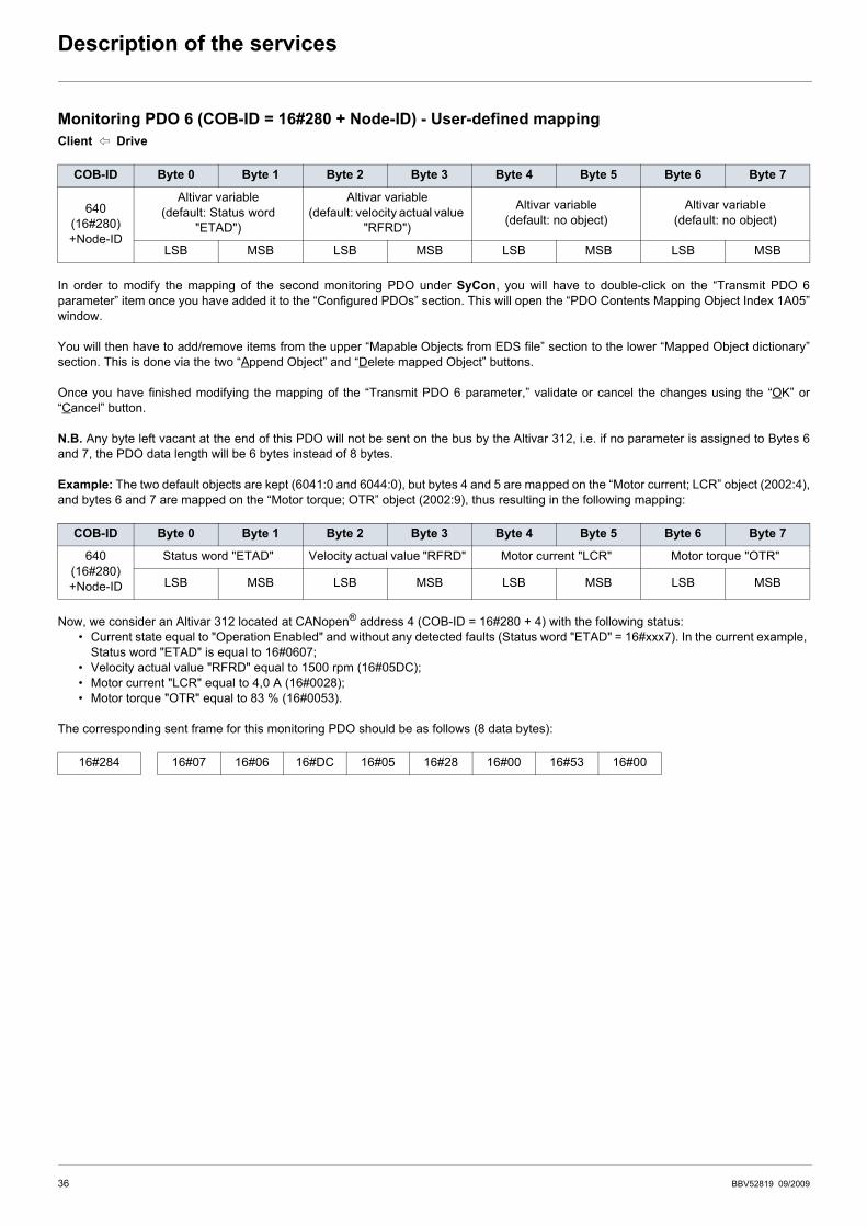
Monitoring PDO 6 (COB-ID = 16#280 + Node-ID) - User-defined mappingClient B Drive
In order to modify the mapping of the second monitoring PDO under SyCon, you will have to double-click on the “Transmit PDO 6parameter” item once you have added it to the “Configured PDOs” section. This will open the “PDO Contents Mapping Object Index 1A05”window.
You will then have to add/remove items from the upper “Mapable Objects from EDS file” section to the lower “Mapped Object dictionary”section. This is done via the two “Append Object” and “Delete mapped Object” buttons.
Once you have finished modifying the mapping of the “Transmit PDO 6 parameter,” validate or cancel the changes using the “OK” or“Cancel” button.
N.B. Any byte left vacant at the end of this PDO will not be sent on the bus by the Altivar 312, i.e. if no parameter is assigned to Bytes 6and 7, the PDO data length will be 6 bytes instead of 8 bytes.
Example: The two default objects are kept (6041:0 and 6044:0), but bytes 4 and 5 are mapped on the “Motor current; LCR” object (2002:4),and bytes 6 and 7 are mapped on the “Motor torque; OTR” object (2002:9), thus resulting in the following mapping:
Now, we consider an Altivar 312 located at CANopen® address 4 (COB-ID = 16#280 + 4) with the following status:• Current state equal to "Operation Enabled" and without any detected faults (Status word "ETAD" = 16#xxx7). In the current example,
Status word "ETAD" is equal to 16#0607;• Velocity actual value "RFRD" equal to 1500 rpm (16#05DC);• Motor current "LCR" equal to 4,0 A (16#0028);• Motor torque "OTR" equal to 83 % (16#0053).
The corresponding sent frame for this monitoring PDO should be as follows (8 data bytes):
COB-ID Byte 0 Byte 1 Byte 2 Byte 3 Byte 4 Byte 5 Byte 6 Byte 7
640(16#280)+Node-ID
Altivar variable(default: Status word
"ETAD")
Altivar variable(default: velocity actual value
"RFRD")
Altivar variable(default: no object)
Altivar variable(default: no object)
LSB MSB LSB MSB LSB MSB LSB MSB
COB-ID Byte 0 Byte 1 Byte 2 Byte 3 Byte 4 Byte 5 Byte 6 Byte 7
640(16#280)+Node-ID
Status word "ETAD" Velocity actual value "RFRD" Motor current "LCR" Motor torque "OTR"
LSB MSB LSB MSB LSB MSB LSB MSB
16#284 16#07 16#06 16#DC 16#05 16#28 16#00 16#53 16#00
36 BBV52819 09/2009
Description of the services
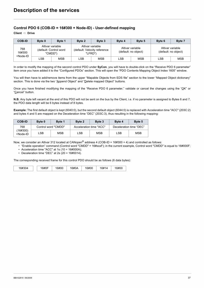
Control PDO 6 (COB-ID = 16#300 + Node-ID) - User-defined mappingClient C Drive
In order to modify the mapping of the second control PDO under SyCon, you will have to double-click on the “Receive PDO 6 parameter”item once you have added it to the “Configured PDOs” section. This will open the “PDO Contents Mapping Object Index 1605” window.
You will then have to add/remove items from the upper “Mapable Objects from EDS file” section to the lower “Mapped Object dictionary”section. This is done via the two “Append Object” and “Delete mapped Object” buttons.
Once you have finished modifying the mapping of the “Receive PDO 6 parameter,” validate or cancel the changes using the “OK” or“Cancel” button.
N.B. Any byte left vacant at the end of this PDO will not be sent on the bus by the Client, i.e. if no parameter is assigned to Bytes 6 and 7,the PDO data length will be 6 bytes instead of 8 bytes.
Example: The first default object is kept (6040:0), but the second default object (6044:0) is replaced with Acceleration time "ACC" (203C:2)and bytes 4 and 5 are mapped on the Deceleration time “DEC” (203C:3), thus resulting in the following mapping:
Now, we consider an Altivar 312 located at CANopen® address 4 (COB-ID = 16#300 + 4) and controlled as follows:• “Enable operation” command (Control word "CMDD" = 16#xxxF); in the current example, Control word "CMDD" is equal to 16#000F;• Acceleration time "ACC" at 1s (10 = 16#000A);• Deceleration time “DEC” at 2s (20 = 16#0014).
The corresponding received frame for this control PDO should be as follows (6 data bytes):
COB-ID Byte 0 Byte 1 Byte 2 Byte 3 Byte 4 Byte 5 Byte 6 Byte 7
76816#300
+Node-ID
Altivar variable(default: Control word
"CMDD")
Altivar variable(default: Velocity reference
"LFRD")
Altivar variable(default: no object)
Altivar variable(default: no object)
LSB MSB LSB MSB LSB MSB LSB MSB
COB-ID Byte 0 Byte 1 Byte 2 Byte 3 Byte 4 Byte 5
768(16#300)+Node-ID
Control word "CMDD" Acceleration time "ACC" Deceleration time “DEC”
LSB MSB LSB MSB LSB MSB
16#304 16#0F 16#00 16#0A 16#00 16#14 16#00
BBV52819 09/2009 37
Description of the services
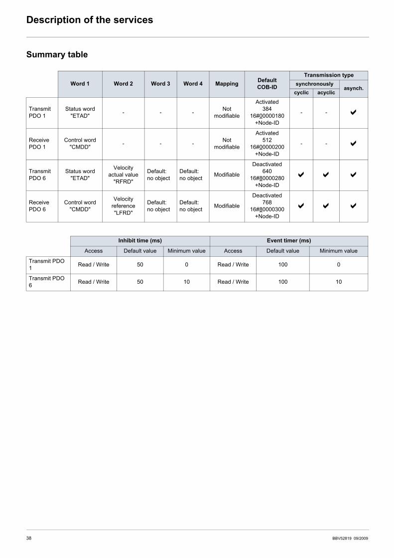
Summary table
Word 1 Word 2 Word 3 Word 4 Mapping Default COB-ID
Transmission typesynchronously
asynch.cyclic acyclic
TransmitPDO 1
Status word"ETAD" - - - Not
modifiable
Activated384
16#00000180+Node-ID
- -
ReceivePDO 1
Control word "CMDD" - - - Not
modifiable
Activated512
16#00000200+Node-ID
- -
TransmitPDO 6
Status word "ETAD"
Velocity actual value
"RFRD"
Default:no object
Default:no object Modifiable
Deactivated640
16#80000280+Node-ID
ReceivePDO 6
Control word "CMDD"
Velocityreference"LFRD"
Default:no object
Default:no object Modifiable
Deactivated768
16#80000300+Node-ID
Inhibit time (ms) Event timer (ms)
Access Default value Minimum value Access Default value Minimum value
Transmit PDO 1 Read / Write 50 0 Read / Write 100 0
Transmit PDO 6 Read / Write 50 10 Read / Write 100 10
38 BBV52819 09/2009
Description of the services
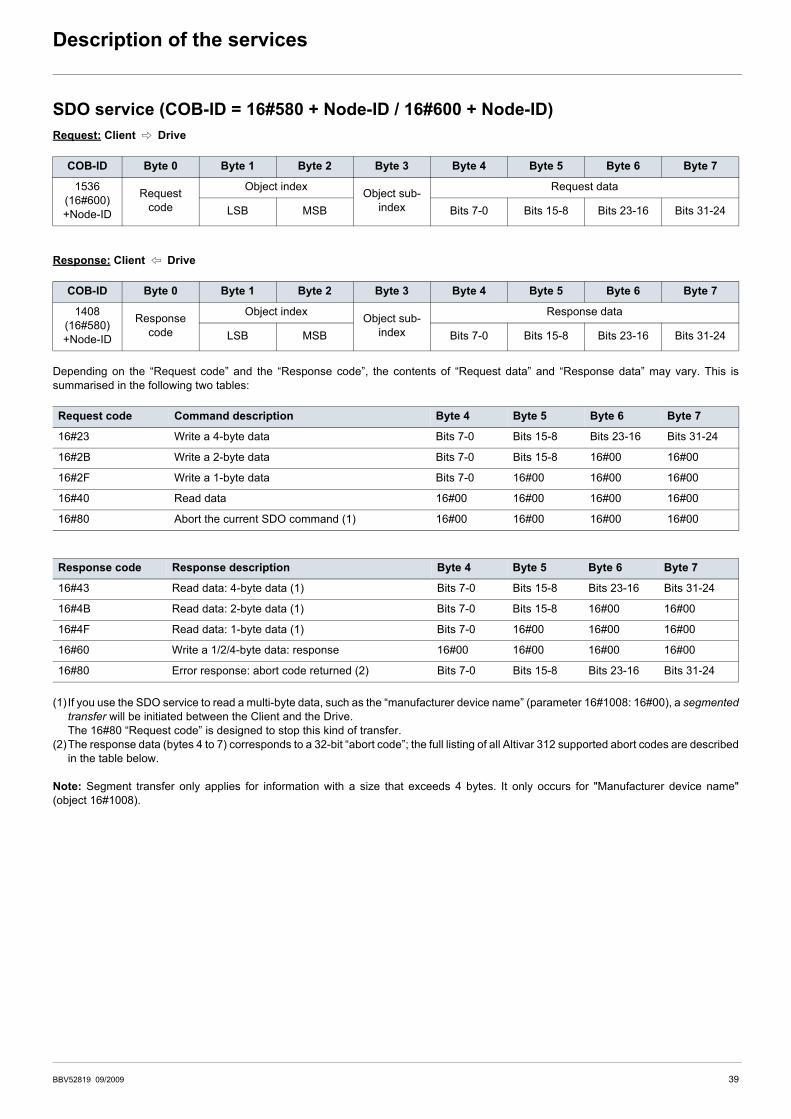
SDO service (COB-ID = 16#580 + Node-ID / 16#600 + Node-ID)Request: Client C Drive
Response: Client B Drive
Depending on the “Request code” and the “Response code”, the contents of “Request data” and “Response data” may vary. This issummarised in the following two tables:
(1) If you use the SDO service to read a multi-byte data, such as the “manufacturer device name” (parameter 16#1008: 16#00), a segmentedtransfer will be initiated between the Client and the Drive.The 16#80 “Request code” is designed to stop this kind of transfer.
(2)The response data (bytes 4 to 7) corresponds to a 32-bit “abort code”; the full listing of all Altivar 312 supported abort codes are describedin the table below.
Note: Segment transfer only applies for information with a size that exceeds 4 bytes. It only occurs for "Manufacturer device name"(object 16#1008).
COB-ID Byte 0 Byte 1 Byte 2 Byte 3 Byte 4 Byte 5 Byte 6 Byte 7
1536(16#600)+Node-ID
Requestcode
Object index Object sub-index
Request data
LSB MSB Bits 7-0 Bits 15-8 Bits 23-16 Bits 31-24
COB-ID Byte 0 Byte 1 Byte 2 Byte 3 Byte 4 Byte 5 Byte 6 Byte 7
1408(16#580)+Node-ID
Responsecode
Object index Object sub-index
Response data
LSB MSB Bits 7-0 Bits 15-8 Bits 23-16 Bits 31-24
Request code Command description Byte 4 Byte 5 Byte 6 Byte 7
16#23 Write a 4-byte data Bits 7-0 Bits 15-8 Bits 23-16 Bits 31-24
16#2B Write a 2-byte data Bits 7-0 Bits 15-8 16#00 16#00
16#2F Write a 1-byte data Bits 7-0 16#00 16#00 16#00
16#40 Read data 16#00 16#00 16#00 16#00
16#80 Abort the current SDO command (1) 16#00 16#00 16#00 16#00
Response code Response description Byte 4 Byte 5 Byte 6 Byte 7
16#43 Read data: 4-byte data (1) Bits 7-0 Bits 15-8 Bits 23-16 Bits 31-24
16#4B Read data: 2-byte data (1) Bits 7-0 Bits 15-8 16#00 16#00
16#4F Read data: 1-byte data (1) Bits 7-0 16#00 16#00 16#00
16#60 Write a 1/2/4-byte data: response 16#00 16#00 16#00 16#00
16#80 Error response: abort code returned (2) Bits 7-0 Bits 15-8 Bits 23-16 Bits 31-24
BBV52819 09/2009 39

Description of the services
(1)Please note that the “Abort codes” listed in this table are written in the usual representation and thus must be inverted on a byte-by-bytebasis for the “Byte 4 to 7” representation (e.g. 16# 0609 0030 becomes Byte 4 = 16#30, Byte 5 = 16#00, Byte 6 = 16#09, Byte 7 = 16#06).
Important notes regarding the SDO service
Abort code (1) Description
16# 0503 0000 Segmented transfer: the “toggle bit” has not been alternated
16# 0504 0000 The SDO protocol timed out
16# 0504 0001 The “request code” is not valid or is unknown
16# 0601 0000 An access fault has been detected during access to the parameter (e.g. a write request on a “read only” parameter)
16# 0601 0001 Tried to perform a read request on a parameter with “write only” access rights
16# 0601 0002 Tried to perform a write request on a parameter with “read only” access rights
16# 0602 0000 The “index” passed in the request refers to an object that does not exist in the object dictionary
16# 0604 0041 PDO object mapping: the parameter cannot be mapped to the PDO; this error occurs when writing to the 16#1600, 16#1A00, 16#1605, and 16#1A05 parameters (PDO mappings)
16# 0604 0042 PDO object mapping: the number and/or length of the parameters to be mapped would exceed the maximum PDO length.
16# 0609 0011 The “sub-index” passed in the request does not exist
16# 0609 0030 Value range of parameter exceeded (only for write access)
16# 0609 0031 Value of parameter written too high
16# 0609 0032 Value of parameter written too low
16# 0609 0036 The parameter maximum value is less than its minimum value
16# 0800 0000 A general error has been detected.
Note: Do not use SDO write requests on the parameters included in the “Transmit PDOs” you have configured under SyCon.For the “Transmit PDO 1”, this constraint applies to Control word "CMDD".For the “Transmit PDO 6”, Control word "CMDD" and Velocity reference "LFRD" are both configured by default. If you replace one or both of these default parameters, or if you add one or two other parameters to this PDO, this restriction applies to these configured parameters.
Note: Any parameter directly connected to one of the parameters placed under the previous restriction must not be modified using a SDO write request.
40 BBV52819 09/2009
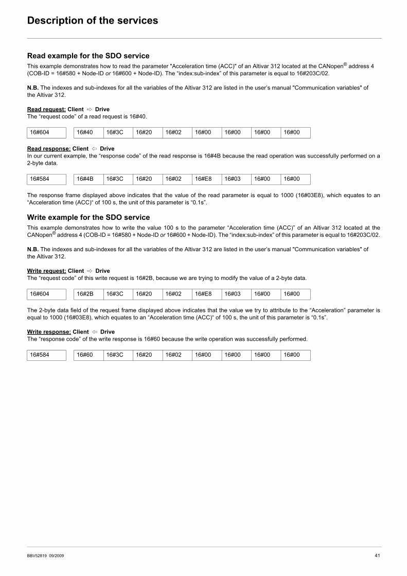
Description of the services
Read example for the SDO serviceThis example demonstrates how to read the parameter "Acceleration time (ACC)" of an Altivar 312 located at the CANopen® address 4(COB-ID = 16#580 + Node-ID or 16#600 + Node-ID). The “index:sub-index” of this parameter is equal to 16#203C/02.
N.B. The indexes and sub-indexes for all the variables of the Altivar 312 are listed in the user’s manual "Communication variables" of the Altivar 312.
Read request: Client C DriveThe “request code” of a read request is 16#40.
Read response: Client B DriveIn our current example, the “response code” of the read response is 16#4B because the read operation was successfully performed on a2-byte data.
The response frame displayed above indicates that the value of the read parameter is equal to 1000 (16#03E8), which equates to an“Acceleration time (ACC)“ of 100 s, the unit of this parameter is “0.1s”.
Write example for the SDO serviceThis example demonstrates how to write the value 100 s to the parameter “Acceleration time (ACC)” of an Altivar 312 located at theCANopen® address 4 (COB-ID = 16#580 + Node-ID or 16#600 + Node-ID). The “index:sub-index” of this parameter is equal to 16#203C/02.
N.B. The indexes and sub-indexes for all the variables of the Altivar 312 are listed in the user’s manual "Communication variables" of the Altivar 312.
Write request: Client C DriveThe “request code” of this write request is 16#2B, because we are trying to modify the value of a 2-byte data.
The 2-byte data field of the request frame displayed above indicates that the value we try to attribute to the “Acceleration” parameter isequal to 1000 (16#03E8), which equates to an “Acceleration time (ACC)“ of 100 s, the unit of this parameter is “0.1s”.
Write response: Client B DriveThe “response code” of the write response is 16#60 because the write operation was successfully performed.
16#604 16#40 16#3C 16#20 16#02 16#00 16#00 16#00 16#00
16#584 16#4B 16#3C 16#20 16#02 16#E8 16#03 16#00 16#00
16#604 16#2B 16#3C 16#20 16#02 16#E8 16#03 16#00 16#00
16#584 16#60 16#3C 16#20 16#02 16#00 16#00 16#00 16#00
BBV52819 09/2009 41
Description of the services
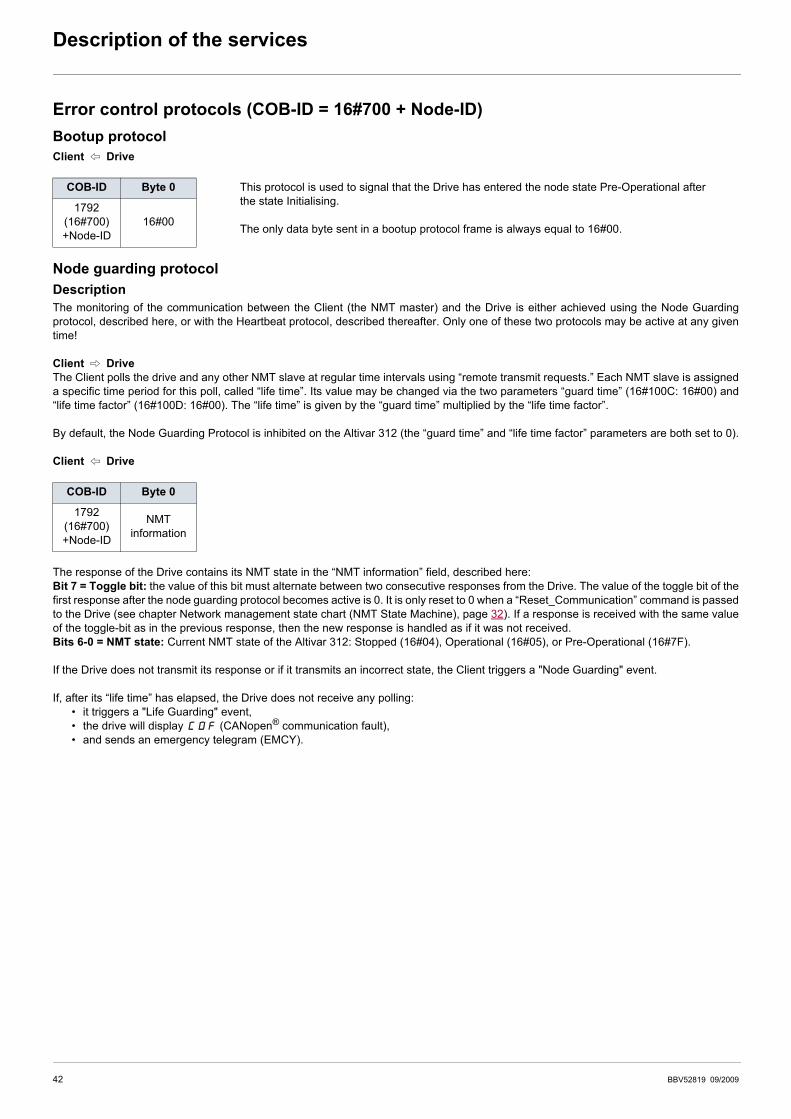
Error control protocols (COB-ID = 16#700 + Node-ID)Bootup protocolClient B Drive
Node guarding protocolDescriptionThe monitoring of the communication between the Client (the NMT master) and the Drive is either achieved using the Node Guardingprotocol, described here, or with the Heartbeat protocol, described thereafter. Only one of these two protocols may be active at any giventime!
Client C DriveThe Client polls the drive and any other NMT slave at regular time intervals using “remote transmit requests.” Each NMT slave is assigneda specific time period for this poll, called “life time”. Its value may be changed via the two parameters “guard time” (16#100C: 16#00) and“life time factor” (16#100D: 16#00). The “life time” is given by the “guard time” multiplied by the “life time factor”.
By default, the Node Guarding Protocol is inhibited on the Altivar 312 (the “guard time” and “life time factor” parameters are both set to 0).
Client B Drive
The response of the Drive contains its NMT state in the “NMT information” field, described here:Bit 7 = Toggle bit: the value of this bit must alternate between two consecutive responses from the Drive. The value of the toggle bit of thefirst response after the node guarding protocol becomes active is 0. It is only reset to 0 when a “Reset_Communication” command is passedto the Drive (see chapter Network management state chart (NMT State Machine), page 32). If a response is received with the same valueof the toggle-bit as in the previous response, then the new response is handled as if it was not received.Bits 6-0 = NMT state: Current NMT state of the Altivar 312: Stopped (16#04), Operational (16#05), or Pre-Operational (16#7F).
If the Drive does not transmit its response or if it transmits an incorrect state, the Client triggers a "Node Guarding" event.
If, after its “life time” has elapsed, the Drive does not receive any polling:• it triggers a "Life Guarding" event,• the drive will display COF (CANopen® communication fault),• and sends an emergency telegram (EMCY).
COB-ID Byte 0 This protocol is used to signal that the Drive has entered the node state Pre-Operational after the state Initialising.
The only data byte sent in a bootup protocol frame is always equal to 16#00.
1792(16#700)+Node-ID
16#00
COB-ID Byte 0
1792(16#700)+Node-ID
NMTinformation
42 BBV52819 09/2009

Description of the services
Example of node guarding protocol setupAs described earlier, the “life time” of the Altivar 312 may be modified using the SDO service in order to write new values for its “guard time”and “life time factor” parameters.
In the current example, we will configure a “life time” of 2 seconds, with a “guard time” of 500 ms and a “life time factor” equal to 4 (500 ms × 4 = 2 s).
1) Setting up the “guard time” to 500 ms• COB-ID = 16#600 + Node-ID for the write request, or 16#580 + Node-ID for the write response• Request code (byte 0) = 16#2B for writing a 2-byte data• Response code (byte 0) = 16#60 if the write operation has been successfully carried out• Object index (bytes 1 and 2) = 16#100C• Object sub-index (byte 3) = 16#00• Request data (bytes 4 and 5) = 16#01F4 (500)
Request: Client C Drive
Response: Client B Drive
2) Setting up the “life time factor” to 4• COB-ID = 16#600 + Node-ID for the write request, or 16#580 + Node-ID for the write response• Request code (byte 0) = 16#2F for writing a 1-byte data• Response code (byte 0) = 16#60 if the write operation has been successfully carried out• Object index (bytes 1 and 2) = 16#100D• Object sub-index (byte 3) = 16#00• Request data (byte 4) = 16#04 (4)
Request: Client C Drive
Response: Client B Drive
Corresponding PL7 instructions (in ST language):
Parameter Index Sub-index Format Unit
Guard time 16# 100C 16# 00 16-bit unsigned integer 1 ms
Life time factor 16# 100D 16# 00 unsigned byte __
16#604 16#2B 16#0C 16#10 16#00 16#F4 16#01 16#00 16#00
16#584 16#60 16#0C 16#10 16#00 16#00 16#00 16#00 16#00
16#604 16#2F 16#0D 16#10 16#00 16#04 16#00 16#00 16#00
16#584 16#60 16#0D 16#10 16#00 16#00 16#00 16#00 16#00
%MW1000:=16#01F4;(* Data to Send = Guard Time = 500 *)%MW1001:=16#04;(* Data to Send = Life Time Factor = 4 *)%MW22:=50;(* Timeout = 50 x 10 ms = 500 ms *)%MW23:=4;(* Data length = 4 bytes *)(* SENDS the SDO WRITE commands *)WRITE_VAR(ADR#0.1.SYS,'SDO',16#0000100C,4,%MW1000:1,%MW20:4);WRITE_VAR(ADR#0.1.SYS,'SDO',16#0000100D,4,%MW1001:1,%MW20:4)
BBV52819 09/2009 43
Description of the services
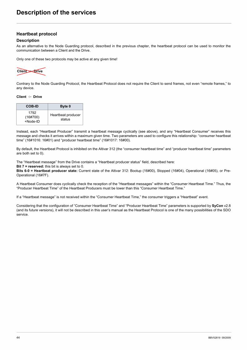
Heartbeat protocolDescriptionAs an alternative to the Node Guarding protocol, described in the previous chapter, the heartbeat protocol can be used to monitor thecommunication between a Client and the Drive.
Only one of these two protocols may be active at any given time!
Contrary to the Node Guarding Protocol, the Heartbeat Protocol does not require the Client to send frames, not even “remote frames,” toany device.
Client B Drive
Instead, each “Heartbeat Producer” transmit a heartbeat message cyclically (see above), and any “Heartbeat Consumer” receives thismessage and checks it arrives within a maximum given time. Two parameters are used to configure this relationship: “consumer heartbeattime” (16#1016: 16#01) and “producer heartbeat time” (16#1017: 16#00).
By default, the Heartbeat Protocol is inhibited on the Altivar 312 (the “consumer heartbeat time” and “producer heartbeat time” parametersare both set to 0).
The “Heartbeat message” from the Drive contains a “Heartbeat producer status” field, described here:Bit 7 = reserved: this bit is always set to 0.Bits 6-0 = Heartbeat producer state: Current state of the Altivar 312: Bootup (16#00), Stopped (16#04), Operational (16#05), or Pre-Operational (16#7F).
A Heartbeat Consumer does cyclically check the reception of the “Heartbeat messages” within the “Consumer Heartbeat Time.” Thus, the“Producer Heartbeat Time” of the Heartbeat Producers must be lower than this “Consumer Heartbeat Time.”
If a “Heartbeat message” is not received within the “Consumer Heartbeat Time,” the consumer triggers a “Heartbeat” event.
Considering that the configuration of “Consumer Heartbeat Time” and “Producer Heartbeat Time” parameters is supported by SyCon v2.8(and its future versions), it will not be described in this user’s manual as the Heartbeat Protocol is one of the many possibilities of the SDOservice.
COB-ID Byte 0
1792(16#700)+Node-ID
Heartbeat producer status
Client C Drive
44 BBV52819 09/2009

Object dictionary
General contents of the object dictionaryThe general breakdown of the Altivar 312 object dictionary is the same for all CANopen® devices:
Index Object
16#0000 Unused
16#0001 - 16#001F Static data types
16#0020 - 16#003F Complex data types
16#0040 - 16#005F Unused (Manufacturer specific complex data types)
16#0060 - 16#007F Device profile specific static data types
16#0080 - 16#009F Device profile specific complex data types
16#00A0 - 16#0FFF Reserved for further use
16#1000 - 16#1FFF Communication profile area
16#2000 - 16#5FFF Altivar 312 specific profile area
16#6000 - 16#9FFF Standardised device profile area
16#A000 - 16#FFFF Reserved for further use
BBV52819 09/2009 45
Object dictionary
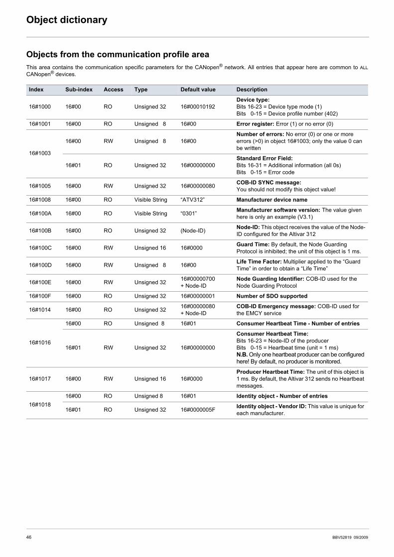
Objects from the communication profile areaThis area contains the communication specific parameters for the CANopen® network. All entries that appear here are common to ALLCANopen® devices.
Index Sub-index Access Type Default value Description
16#1000 16#00 RO Unsigned 32 16#00010192Device type:Bits 16-23 = Device type mode (1)Bits 00-15 = Device profile number (402)
16#1001 16#00 RO Unsigned 08 16#00 Error register: Error (1) or no error (0)
16#1003
16#00 RW Unsigned 08 16#00Number of errors: No error (0) or one or more errors (>0) in object 16#1003; only the value 0 can be written
16#01 RO Unsigned 32 16#00000000Standard Error Field:Bits 16-31 = Additional information (all 0s)Bits 00-15 = Error code
16#1005 16#00 RW Unsigned 32 16#00000080 COB-ID SYNC message:You should not modify this object value!
16#1008 16#00 RO Visible String “ATV312” Manufacturer device name
16#100A 16#00 RO Visible String “0301” Manufacturer software version: The value given here is only an example (V3.1)
16#100B 16#00 RO Unsigned 32 (Node-ID) Node-ID: This object receives the value of the Node-ID configured for the Altivar 312
16#100C 16#00 RW Unsigned 16 16#0000 Guard Time: By default, the Node Guarding Protocol is inhibited; the unit of this object is 1 ms.
16#100D 16#00 RW Unsigned 08 16#00 Life Time Factor: Multiplier applied to the “Guard Time” in order to obtain a “Life Time”
16#100E 16#00 RW Unsigned 32 16#00000700+ Node-ID
Node Guarding Identifier: COB-ID used for the Node Guarding Protocol
16#100F 16#00 RO Unsigned 32 16#00000001 Number of SDO supported
16#1014 16#00 RO Unsigned 32 16#00000080+ Node-ID
COB-ID Emergency message: COB-ID used for the EMCY service
16#1016
16#00 RO Unsigned08 16#01 Consumer Heartbeat Time - Number of entries
16#01 RW Unsigned 32 16#00000000
Consumer Heartbeat Time:Bits 16-23 = Node-ID of the producerBits 00-15 = Heartbeat time (unit = 1 ms)N.B. Only one heartbeat producer can be configured here! By default, no producer is monitored.
16#1017 16#00 RW Unsigned 16 16#0000Producer Heartbeat Time: The unit of this object is 1 ms. By default, the Altivar 312 sends no Heartbeat messages.
16#101816#00 RO Unsigned 8 16#01 Identity object - Number of entries
16#01 RO Unsigned 32 16#0000005F Identity object - Vendor ID: This value is unique for each manufacturer.
46 BBV52819 09/2009
Object dictionary
Index Sub-index Access Type Default value Description
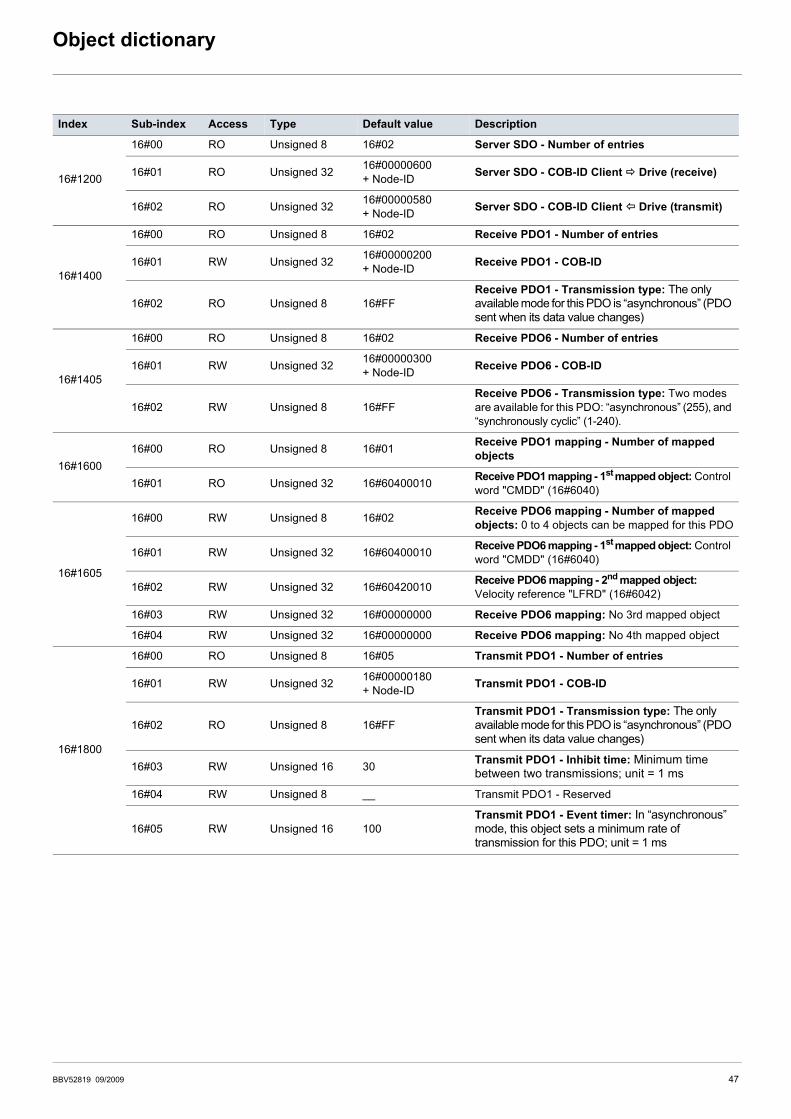
16#1200
16#00 RO Unsigned 8 16#02 Server SDO - Number of entries
16#01 RO Unsigned 32 16#00000600+ Node-ID Server SDO - COB-ID Client Drive (receive)
16#02 RO Unsigned 32 16#00000580+ Node-ID Server SDO - COB-ID Client Drive (transmit)
16#1400
16#00 RO Unsigned 8 16#02 Receive PDO1 - Number of entries
16#01 RW Unsigned 32 16#00000200+ Node-ID Receive PDO1 - COB-ID
16#02 RO Unsigned 8 16#FFReceive PDO1 - Transmission type: The only available mode for this PDO is “asynchronous” (PDO sent when its data value changes)
16#1405
16#00 RO Unsigned 8 16#02 Receive PDO6 - Number of entries
16#01 RW Unsigned 32 16#00000300+ Node-ID Receive PDO6 - COB-ID
16#02 RW Unsigned 8 16#FFReceive PDO6 - Transmission type: Two modes are available for this PDO: “asynchronous” (255), and “synchronously cyclic” (1-240).
16#160016#00 RO Unsigned 8 16#01 Receive PDO1 mapping - Number of mapped
objects
16#01 RO Unsigned 32 16#60400010 Receive PDO1 mapping - 1st mapped object: Control word "CMDD" (16#6040)
16#1605
16#00 RW Unsigned 8 16#02 Receive PDO6 mapping - Number of mapped objects: 0 to 4 objects can be mapped for this PDO
16#01 RW Unsigned 32 16#60400010 Receive PDO6 mapping - 1st mapped object: Control word "CMDD" (16#6040)
16#02 RW Unsigned 32 16#60420010 Receive PDO6 mapping - 2nd mapped object: Velocity reference "LFRD" (16#6042)
16#03 RW Unsigned 32 16#00000000 Receive PDO6 mapping: No 3rd mapped object
16#04 RW Unsigned 32 16#00000000 Receive PDO6 mapping: No 4th mapped object
16#1800
16#00 RO Unsigned 8 16#05 Transmit PDO1 - Number of entries
16#01 RW Unsigned 32 16#00000180+ Node-ID Transmit PDO1 - COB-ID
16#02 RO Unsigned 8 16#FFTransmit PDO1 - Transmission type: The only available mode for this PDO is “asynchronous” (PDO sent when its data value changes)
16#03 RW Unsigned 16 30 Transmit PDO1 - Inhibit time: Minimum time between two transmissions; unit = 1 ms
16#04 RW Unsigned 8 __ Transmit PDO1 - Reserved
16#05 RW Unsigned 16 100Transmit PDO1 - Event timer: In “asynchronous” mode, this object sets a minimum rate of transmission for this PDO; unit = 1 ms
BBV52819 09/2009 47
Object dictionary
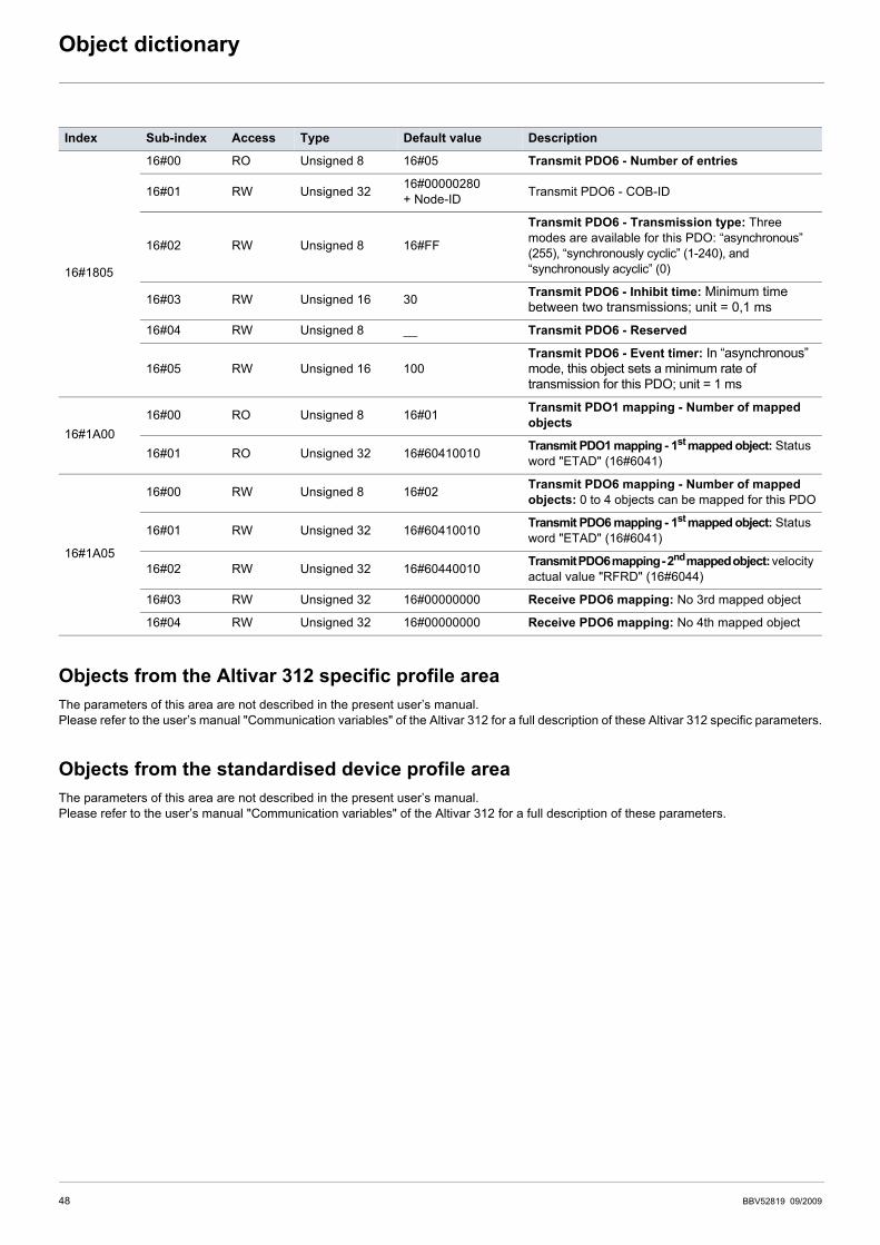
Objects from the Altivar 312 specific profile areaThe parameters of this area are not described in the present user’s manual.Please refer to the user’s manual "Communication variables" of the Altivar 312 for a full description of these Altivar 312 specific parameters.
Objects from the standardised device profile areaThe parameters of this area are not described in the present user’s manual.Please refer to the user’s manual "Communication variables" of the Altivar 312 for a full description of these parameters.
Index Sub-index Access Type Default value Description
16#1805
16#00 RO Unsigned 8 16#05 Transmit PDO6 - Number of entries
16#01 RW Unsigned 32 16#00000280+ Node-ID Transmit PDO6 - COB-ID
16#02 RW Unsigned 8 16#FF
Transmit PDO6 - Transmission type: Three modes are available for this PDO: “asynchronous” (255), “synchronously cyclic” (1-240), and “synchronously acyclic” (0)
16#03 RW Unsigned 16 30 Transmit PDO6 - Inhibit time: Minimum time between two transmissions; unit = 0,1 ms
16#04 RW Unsigned 8 __ Transmit PDO6 - Reserved
16#05 RW Unsigned 16 100Transmit PDO6 - Event timer: In “asynchronous” mode, this object sets a minimum rate of transmission for this PDO; unit = 1 ms
16#1A0016#00 RO Unsigned 8 16#01 Transmit PDO1 mapping - Number of mapped
objects
16#01 RO Unsigned 32 16#60410010 Transmit PDO1 mapping - 1st mapped object: Status word "ETAD" (16#6041)
16#1A05
16#00 RW Unsigned 8 16#02 Transmit PDO6 mapping - Number of mapped objects: 0 to 4 objects can be mapped for this PDO
16#01 RW Unsigned 32 16#60410010 Transmit PDO6 mapping - 1st mapped object: Status word "ETAD" (16#6041)
16#02 RW Unsigned 32 16#60440010 Transmit PDO6 mapping - 2nd mapped object: velocity actual value "RFRD" (16#6044)
16#03 RW Unsigned 32 16#00000000 Receive PDO6 mapping: No 3rd mapped object
16#04 RW Unsigned 32 16#00000000 Receive PDO6 mapping: No 4th mapped object
48 BBV52819 09/2009

BBV52819
ATV312_CANopen_BBV52819_02
09/2009