audievolve documentation 2013
DESCRIPTION
Stanford ME310 - 2013TRANSCRIPT

EV E
ME310 2013 Final DocumentationAudi Team
Transforming the journey into the destination

Final Documentation2
Audi CorporationMechanical Engineering 310Fall Design Documentation
Version: 10.12.2012.Dept. of Mechanical EngineeringStanford UniversityStanford, CA 94305-4021
In Partnership With:Aalto University, Helsinki, Finland
Final Documentation 3
1. Prelude

Final Documentation4
1.1 Executive summaryWith the advent of new robotic and autonomous technologies, it was only a matter of time until it crossed over to vehicle design. The development in the area of autonomous cars has already reached levels that have made it possible for companies like Google to manufacture and test out self-driving cars, which have already clocked over 200,000 miles in the US [10]. It is not just the technology that is developing; the entire support system is changing as autonomous cars have been legalized in three states in the US. Personal mobility currently is often perceived as driving in a vehicle. It is this perception that is about to change; mobility will not just be about driving anymore. Driving is not the primary task that would be performed in autonomous cars. These cars would offer a wide range of options for various activities the user can do inside the car while it is driving them around.Team Audi Evolve consists of a combined team of mechanical and electrical engineers, product designers, industrial designers and business school students from Stanford University and Aalto University in Finland. The team envisions a future where cabin space designs of autonomous cars will have transformed the journey into the destination. The aim is to offer a solution for 2035 where drivers can easily work and enjoy their free time, while maintaining the pleasure of driving. This makes it important to focus on the issue of transitioning between various activities and driving.The important areas that have been identified in the design space are psychological,
physical and experiential. The team went through several stages of prototyping to explore the design space. The initial focus was on a safe transition from autonomous to manual driving mode. The main idea tested was that of the steps involved in a safe transfer of control to the user. The turning point for this project came with a prototype exploring a reconfigurable cabin space design in cars. It was after this prototype that the focus shifted on the actual experience of the transition. Users who will adopt this technology in the future are people who will still want to drive along with performing other activities in the cabin space during autonomous mode. They will multi-task a lot and always stay connected, therefore changing positions frequently.Since people will often be performing many different activities while in the car, creating an excellent riding experience is just as important as an excellent driving experience. The team is designing a system that will lead to smooth and comfortable transitions not only to and from driving mode, but also for transitions between other activities. This will also help people regain time lost in commuting by creating a cabin space that is adaptable to many activities and removes tedious manual adjustments.The designed system will give the user complete flexibility to perform different
“ Your autonomous car is your personal driver in the future! ”

Final Documentation 5
activities in the cabin space. The car seat and the steering mechanism are important components in the cabin space, which will affect the freedom of motion and ability to perform various activities in a comfortable way. The team envisions that the system will consist of a smart chair and a retractable steering wheel. The main motivating factors for the retractable steering design were increasing mobility within the cabin space and relieving the users of the responsibility of monitoring autonomous driving when in autonomous mode. While the steering wheel is retracted and locked for autonomous mode, the tablet is enabled so that the user can interact with the windshield. When the steering wheel is not retracted it is free to rotate so that the driver can have manual control of the car. There are three different
interactions with the system – Mode Initiators (MI) are intentional actions within reach like pulling the steering wheel to go into manual driving mode and pushing on the steering wheel to make it retract. The user can also use Intentional Body Commands (IBC) like leaning back to tilt the seat. The chair can also give Adaptive Chair Reactions (ACR) to movements of the users like rotating slightly when they reach for something at the back of the car.This new cabin space experience allows for the driver to rotate 180 degrees to be able to socialize with other passengers. Having only one seat in the front also increases the mobility within the cabin, while also making the driver’s seat very desirable. This configuration allows the driver to better share the driving experience with
Figure 1.1.1: Final Prototype

Final Documentation6
the passengers since it increases their view of the road as well. Our final prototype will give the experience of facilitated activities through increasing mobility and effortlessly transitioning between activities for the driver. Going forward, the team will incorporate many of the findings uncovered in all of the prototypes, research, and needfinding into a functioning system. The development described herein leads to a vision combining many of the concepts explored during the last few months. Through a continued process of rapid prototyping and additional user testing, the team plans to present a highly refined and fully functioning system in June 2013.
1.2 Project BackgroundOver the last 100 years personal vehicles have become one of the most heavily used means of transportation in developed countries. In many ways, cars define who we are, what we do and how we travel. Along with increased mobility, cars have brought about tremendous changes to the way we live and interact. Over the period of time, in addition to being just a medium of transportation, cars have gone to become a medium to experience the sheer pleasure of racing around and driving in a machine that is so responsive to the user’s actions. Indeed a major component of the pleasure of driving lies in the ability to drive on the edge of control and experience the thrill of being out there and taking the risk.
However, this entire landscape is changing as we head towards the age of robots
and artificial intelligence. With so much technological development in these major fields there was bound to be a point when these ideas crossover and start influencing automotive design. As technology develops further, it will lead to a complete paradigm shift in the way cars and automotive technology in general is perceived amongst the general population. Concepts which were just science fiction a few years back, have started becoming real and achievable in the near future. The development in the area of autonomous cars has already reached levels which has made it possible for companies like Google to manufacture and test out self driving cars which have already clocked over 200,000 miles in the US. It is not just the technology that is developing, but the entire support system is changing with autonomous cars being legalised in three states in the US.
Personal mobility currently is often perceived as driving in a vehicle. It is this perception that is about to change, mobility will not just be about driving anymore. Driving is not the primary task that would be performed in autonomous cars. They would offer a wide range of options with users being able to perform various other activities inside the car while it is driving them around.
The major hurdles that lie in the development and adoption of this technology widely are the costs associated with required infrastructure development, legal issues like liability in case of accidents and user acceptability in general. The question that

Final Documentation 7
comes up is what would happen when this would actually launch in the market? Would people be willing to take the leap of faith and trust their life on a computer controlled car? What kind of assurance and trust development would be required for widespread acceptance of autonomous vehicles? These and a lot of other questions and issues are the prime concern of car manufacturers who are willing to step in this field of autonomous car development.
Like any other new technology, it will take time to adopt and build trust on this system but it will happen eventually and once that happens the possibilities that it opens up are enormous. It is not presumptuous to assume that by the year 2035, autonomous cars will have become a common sight. Although they offer relaxation and safety in driving, it is still problematic for users to completely rely on their autonomous functions. Car designers and manufacturers then need to focus on taking advantage of this whole new opportunity to redefine urban mobility and experience with cars.
The car will no longer be a medium for the journey but it will be a productive location where users can perform various activities while being driven around autonomously.
1.3 Project VisionTeam Audi Evolve design team envisions a future where people will still want to drive even though driving will be only a secondary activity. Autonomous driving allows spare time for the driver and ensures increased productivity.
Since people will often be performing different activities while in the car, creating an excellent riding experience is just as important as an excellent driving experience. Switching between manual mode, autonomous mode and different activities within autonomous mode, always includes a transition. It is these transitions that the team hopes to address, as well as ensuring that the cabin has enough mobility in order to perform various activities. The vision of Team Audi Evolve is to facilitate activities for the driver through effortless transitions and increased mobility.
Final Documentation8
1.4 Table of Contents1. Prelude .............................................................................................
1.1 Executive Summary .........................................................
1.2 Project Background ..........................................................
1.3 Project Vision ...................................................................
1.4 Table of Contents .............................................................
1.5 List of Figures ..................................................................
1.6 List of Tables ....................................................................
1.7 Glossary ...........................................................................
2. Context ...........................................................................................
2.1 Need Statement ................................................................
2.2 Problem Statement ..........................................................
2.3 The Design Team ............................................................
2.3.1 The Stanford Team ..........................................
2.3.2 The Aalto Team ................................................
2.4 Corporate Sponsor ...........................................................
2.4.1 Corporate Liaison .............................................
2.5 Teaching Team .................................................................
2.6 Special Thanks ................................................................
3. Design Requirements ...................................................................
3.1. Given Requirements .......................................................
3.2 Functional Requirements ................................................
3.2.1 Functional Opportunities .................................
3.3 Physical Requirements ...................................................
3.3.1 Physical Opportunities ....................................
3.4 Business Opportunity .....................................................
4. Design Development ....................................................................
4.1 Future Assumptions ........................................................
4.1.1 Future User ......................................................
4.1.2 The User story ..................................................
3
4
6
7
8
14
17
17
25
26
26
26
28
30
32
33
33
33
35
36
37
42
43
45
47
49
50
50
52
Final Documentation 9
4.1.3 Future Infrastructure ........................................
4.2 Prototype timeline/ key learnings .....................................
4.3 Finland convergence .......................................................
4.3.1 Vision ...............................................................
4.3.2 Prototype features ............................................
4.4 User testing ......................................................................
4.5 Steering Wheel Concepts for Final Design .......................
4.5.1 Magneto ...........................................................
4.5.2 Retracted steering wheel ..................................
4.6 Final Prototype Development ...........................................
4.6.1 Anticipatory Chair .............................................
4.6.2 Interactive Steering Wheel ...............................
4.6.3 Open and Clear Cabin Space ..........................
5. Design Specifications ..................................................................
5.1 Anticipatory Chair ...........................................................
5.1.1 Chair Electronics ............................................
5.1.1.1 Microcontroller Board .....................
5.1.1.2 Chair Motor Driver Board ................
5.1.1.3 Rotation Motor Driver Board ..............
5.1.1.4 Chair Motor Sensing Board ..............
5.1.1.5 Rotation Optical Encoder .................
5.1.1.6 Force Sensing Resistors ..................
5.1.1.7 Override Switches ............................
5.1.1.8 Master Control Box ..........................
5.1.2 Firmware Development ....................................
5.1.2.1 Tilt Function .....................................
5.1.2.2 Slide Forward/Back Function ............
5.1.2.3. Rotate Function ...............................
5.1.2.4 Move Motor Function .......................
5.1.3 Rotation Mechanism design ............................
5.1.3.1 Assumptions .....................................
52
53
53
56
56
56
58
58
59
60
60
61
61
63
67
68
68
69
70
72
73
74
74
76
77
78
79
79
80
80
81

Final Documentation10
5.1.3.2 Design Calculations ..........................
5.1.3.3 Initial Rotation Prototype ...................
5.1.3.4 Final Rotation Mechanism .................
5.1.4 Cabin Base Design .............................................
5.1.5 Footpad Design .................................................
5.2 Interactive Steering Wheel ................................................
5.2.1 Interactive Steering Wheel Structure ................
5.2.2 The Making of Interactive Steering Wheel .........
5.2.3 The interaction specifications of the steering wheel
5.2.4 Comunication Between Devices ..............
5.3 Open and Clear Cabin Space ..........................................
5.3.1 The Making of Open and Clear Cabin Space ...
6. Project Planning and Management ..............................................
6.1 Timetable and Milestones ................................................
6.2 Budget and Spendings .....................................................
6.3 Distributed Team Management .........................................
6.4 Stanford EXPE ..................................................................
6.5 Future Work ......................................................................
6.6 Personal Reflections .........................................................
7. Appendix ..........................................................................................
7.1 Initial Brief .........................................................................
7.2 Fall Brochure ....................................................................
7.3 Needfinding ......................................................................
7.4 Benchmarking ..................................................................
7.5 Technical Literature Benchmarking ..................................
7.6 Critical Function Prototype – Golf Cart ............................
7.6.1 Golf Cart CFP Results .....................................
7.6.2 Golf Cart – C# Code for Gradual Control ........
7.7 Online Research ..............................................................
7.8 Fall Presentations .............................................................
7.9 Winter Presentation ..........................................................
81
81
82
83
84
85
87
88
90
95
95
97
97
103
104
105
111
112
113
114
127
128
129
131
132
137
141
141
143
154
157

Final Documentation 11
7.10 Winter Brochure ..............................................................
7.11 Dark Horse Prototype .......................................................
7.11.1 “Reconfiguro” - Drag and Drop Interface Java Code
7.12 Funky Prototype .................................................................
7.12.1 Arduino Code for FSR .......................................
7.12.2 Matlab Data Collection Code (main.m) .............
7.12.3 Matlab Data Collection Code (initialize_port.m)
7.12.4 Matlab Data Collection Code (readSerial.m) .....
7.12.5 Matlab Data Collection Code (writeToFile.m) ....
7.12.6 Matlab Post Process Code (post_proc.m) ........
7.13 Functional Prototype .........................................................
7.13.1 Arduino Code - Anticipatory Chair .....................
7.13.2 Arduino Code - “Buckle it Out” ..........................
7.14 Overview ...........................................................................
7.15 Design Reasoning ............................................................
7.16 Development Strategy ......................................................
7.17 Future Assumptions ..........................................................
7.17.1 Future user ........................................................
7.17.2 Future infrastructure ...........................................
7.17.3 Futute technology ...............................................
7.17.4 Ideal Future Persona .........................................
7.18 Needfinding ........................................................................
7.18.1 Context Map .......................................................
7.18.2 Self-Observation ................................................
7.18.3 Interviews ..........................................................
7.18.4 EMT (Emergency Medical Technician) ..............
7.18.5 Survey ................................................................
7.19 Benchmarking ...................................................................
7.19.1 Steering Benchmarking .....................................
7.19.2 Motion Sickness Benchmark .............................
7.19.3 Human-Machine Transition Benchmarking .......
165
168
170
170
191
191
192
193
194
194
194
196
196
220
226
227
229
230
231
232
233
236
238
239
239
241
248
249
253
254
259
Final Documentation12
7.19.4 Confirmation Cue Benchmarking ......................
7.19.5 Trust benchmarking ........................................
7.20 Critical Prototypes ..........................................................
7.20.1 CFP - “Transition Golf Cart” ...........................
7.20.2 Steering Mechanisms ....................................
7.20.3 CEP - “Reconfigurable Workspace” ...............
7.20.4 CEP - “Mobile Workspace” .............................
7.21 Design Specifications ....................................................
7.21.1 Transition sequence prototype .......................
7.21.2 Different Steering Controls .............................
7.22 Needfinding ....................................................................
7.22.1 Trip to Germany .............................................
7.22.2 Geneva Trip ....................................................
7.22.3 Dashboard Questionnaire .............................
7.23 Benchmarking ...............................................................
7.23.1 Akka Car Concept .........................................
7.24 Dark Horse Prototypes .....................................
7.24.1 Dark Horse Prototype - “Reconfiguro” ...........
7.24.2 Dark Horse Prototype - “SbW Imitation” ........
7.24.3 Dark Horse Prototype - “Sleeping Positions”
7.24.4 Dark Horse Prototype - “ AR Imitation” .........
7.24.5 DHP - “Disappearing Steering Wheel” ..........
7.24.6 Dark Horse Prototype - “Magneto” ................
7.25 Funky Prototypes ..........................................................
7.25.1 Funky Prototype ”Anticipatory Chair” ............
7.25.2 Funky Prototype ”What should I do” ..............
7.26 Functional System Prototypes .......................................
7.26.1 FSP ”Anticipatory System” .............................
7.26.2 Functional System Prototype - “Buckle It Out”
260
262
265
270
270
275
282
284
286
286
291
296
296
298
299
301
301
302
302
310
312
314
315
316
318
318
325
330
330
Final Documentation 13
7.27 Design Specifications ....................................................
7.27.1 Design Specifications For Anticipatory Chair
7.27.2 Design Specifications For Anticipatory System
7.27.3 Design Specifications For “Buckle it out” ........
333
336
336
341

Final Documentation14
1.5 List of FiguresFigure 1.1.1: Final Prototype ...............................................................
Figure 2.3.1 - Audi Design Team ........................................................
Figure 2.3.1.1 - Stanford University Logo ..........................................
Figure 2.3.1.2 - Sangram Patil ...........................................................
Figure 2.3.1.3 - Stephanie Tomasetta ................................................
Figure 2.3.1.4 - David Wang ..............................................................
Figure 2.3.2.1 - Aalto University Logo ...............................................
Figure 2.3.2.2 - Goran Bjelajac ..........................................................
Figure 2.3.2.3 - Sifo Luo ....................................................................
Figure 2.3.2.4 - Heikki Sjöman ..........................................................
Figure 2.3.2.5 - Tommi Tuulenmaki ...................................................
Figure 2.4.1 - Audi Logo ....................................................................
Figure 2.4.2 - ERL Logo ....................................................................
Figure 2.5.1 - Aalto Teaching Team ...................................................
Figure 4.1.2.1 - User story ..................................................................
Figure 4.2.1 - Steering Transition CFP ..............................................
Figure 4.2.2 - Steering Mechanisms .................................................
Figure 4.2.3 - Darkhorse prototype ...................................................
Figure 4.2.4 - “Magneto” prototype ...................................................
Figure 4.2.5 - Darkhorse prototype ...................................................
Figure 4.2.5 - Funky Prototype .........................................................
Figure 4.2.6 - Sensing chair ..............................................................
Figure 4.2.7 - Retractable steering wheel Aalto ................................
Figure 4.4.1 - User Testing ................................................................
Figure 4.4.2 - User Testing2 ..............................................................
Figure 4.5.1.1 - User Testing .............................................................
Figure 4.6.2.1 - Early Steering Wheel Mockup ..................................
Table 4.6.2.2 - Retraction Mechanism Explosion ..............................
Table 4.6.3.1 - Cabin Space mock up ...............................................
Figure 5.1.1.1 - System level view ....................................................
5
27
28
28
29
29
30
30
31
31
32
32
32
34
52
53
54
54
54
55
55
55
56
58
58
59
62
63
65
68
Final Documentation 15
Figure 5.1.1.2 - Physical layout of the hardware. ................................
Figure 5.1.1.1.1 - Physical circuit board for the microcontroller ...........
Figure 5.1.1.2.1 - Schematics .............................................................
Figure 5.1.1.2.2 - Physical circuit board .............................................
Figure 5.1.1.3.1 - Dual fan assembly for rotation motor heatsink .......
Figure 5.1.1.4.1 - Motor position sensing circuit schematic .................
Figure 5.1.1.4.2 - Motor position sensing board .................................
Figure 5.1.1.5.1 - Rotation encoder - optical sensor and circle of stripes
Figure 5.1.1.6.1 - Initial configuration of FSR tested ..........................
Figure 5.1.1.6.2 - FSR protoboard .....................................................
Figure 5.1.1.6.3 - FSR circuit schematic ............................................
Figure 5.1.1.7.1 - Switch override circuit schematic and protoboard
Figure 5.1.1.7.2 - Switch override protoboard ...................................
Figure 5.1.1.8.1 - Master control box ................................................
Figure 5.1.2.1 - Firmware process flow .............................................
Figure 5.1.3.2.1 - Chair Dimensions ..................................................
Figure 5.1.3.2.2 - Design Calculations ..............................................
Figure 5.1.3.3.1 - Rotation first prototype 1 ......................................
Figure 5.1.3.3.2 - Rotation first prototype 2 .......................................
Figure 5.1.3.4.1 - Rotation mechanism initial assembly ....................
Figure 5.1.3.4.2 - Rotation connection to platform .............................
Figure 5.1.3.5.3 - Rotation connection to motor ...............................
Figure 5.1.4.1 - Cabin base ...............................................................
Figure 5.1.4.2 - Drawing of the central cabin base design ...............
Figure 5.1.5.1 - top footpad layer ......................................................
Figure 5.1.5.2 - bottom footpad layer ................................................
Figure 5.1.5.3 - middle footpad layer ................................................
Figure 5.1.5.4 - Footpad top view showing wire routing ...................
Figure 5.1.5.5 - Footpad with embedded ball casters ......................
Figure 5.2.1 - 3d Printing of Steering Wheel ....................................
Figure 5.2.1.1 - Steering Wheel .......................................................
69
70
71
71
72
73
73
74
74
75
76
76
77
77
78
80
81
82
82
83
83
83
84
84
85
85
85
85
86
87
88

Final Documentation16
Figure 5.2.1.2 - Steering Wheel Parts ................................................
Figure 5.2.1.3 - Steering Wheel Parts Back .....................................
Figure 5.2.1.4 - Retraction Mechanism Parts ....................................
Figure 5.2.2.1 - Base .........................................................................
Figure 5.2.2.2 - Base Dimensions .....................................................
Figure 5.2.2.3 - Tightening Bands .....................................................
Figure 5.2.2.4 - Tightening Bands Dimensions .................................
Figure 5.2.2.5 - Shaft ........................................................................
Figure 5.2.2.6 - Inner shaft technical drawing ..................................
Figure 5.2.2.7 - Microswitch support ................................................
Figure 5.2.2.8 - Assembled Retraction Mechanism ..........................
Figure 5.2.4.1 - Communication schematics ....................................
Figure 5.2.4.2 - Physical Implementation ..........................................
Figure 5.3.1.1 - Gluing the pieces .....................................................
Figure 5.3.1.2 - Sanding the dashboard ............................................
Figure 5.3.1.3 - Painted dashboard ...................................................
Figure 5.3.1.4 - Banding the ribbon ...................................................
Figure 5.3.1.5 - Barbecuing the ribbon ..............................................
Figure 5.3.1.6 - Mounting the ribbon ..................................................
Figure 6.4.1 - EXPE Booth .................................................................
88
89
89
91
91
92
92
93
94
94
95
96
96
97
98
99
100
100
101
112

Final Documentation 17
1.6 List of TablesTable 3.1.1 : Given Design Requirements ..........................................
Table 3.2.1 : Functional Requirements ...............................................
Table 3.2.1.1 : Functional Opportunities .............................................
Table 3.3.1 : Physical Requirements ...................................................
Table 3.3.1.1: Physical Opportunities ...................................................
Table 3.4.1 : Business Opportunity .....................................................
Table 4.3.2.1 Priorities for EXPE ........................................................
Table 4.3.2.2 Priorities for EXPE ........................................................
Table 4.5.1.1 Pro and Con for Magneto User Testing ........................
Table 4.5.2.1 Pro and Con for Retracting Steering Wheel .................
36
37
42
43
45
47
57
57
59
60
Glossary
Adaptive Cruise Control ACC
This system is much like regular cruise control, it is supposed to maintain certain speed. Adaptive that the car is able to adapt with current surroundings, it is able to keep wanted distance with the car in front.
Adaptive Chair Reaction (ACR)
The chair reaction to changes in body position of the user
Analog-to-Digital Converter (ADC)
This a device that converts a continuous physical quantity (eg. voltage) to a digital data.
1.7 Glossary

Final Documentation18
Glossary
Application Programming Interface (API)
This is a protocol that software components use as an interface for communicating with each other.
Arduino This is a single-board microcontroller.
Augmented Reality (AR)Technology that combines actual world and digitally generated image into one.
Autonomous Mode The mode when car is driving itself.
BenchmarkingAn exercise of exploring as many areas as possible that relate to the problem statement, such as technology research, predictions, etc.
Cabin SpaceThe interior space within a vehicle which is occupied by passengers/drivers.
Confirmation Clue
This means information that the user of a car has to get about the events outside and inside the car. This information confirms that car is behaving the way its user wants it to behave.
Computer Numerically Controlled (CNC)
Controlling method eg for machining tools that uses parameters given by a computer.
Critical Experience Prototype (CEP)
Physical prototype of an experience of design, which is required to ensure usability.
Critical Function Prototype (CFP)
Physical prototype of a fundamental element of design, which is required to ensure its functionality.

Final Documentation 19
Glossary
Dashboard Control panel in front of the driver in a car.
Double Pole, Double Throw (DPDT)
A switch type that includes two SPDT switches
Electroencephalography (EEG)
The recording of brain’s electrical activity along the scalp.
Electronically Erasable Programmable Read-Only Memory (EEPROM)
Type of memory
Emergency Medical Technician (EMT)
Term used in some countries to render to health care provider of an ambulance.
EXPEThe presentation of project outcomes in the end of ME310 course at Stanford.
Field Of View (FOV)The vision field of Kinetic camera device that tracks body movement
Force Sensing Resistor (FSR)
This is a material whose resistance varies if a force is applied.
FlowdockFlowdoc is a collaboration web application for technical team. It allows for quick updates, team communication, and compiles all email threads in one place.
Functional System Prototype
This is a term used for ME310 prototype that is still a bit crude, and obviously assembled from off-the-shelf parts; however, this time decisions ontechnical implementation are done with increased sophistication.
Funky Prototype
This is a term used in ME310 for an approximation prototype of the full system without making a costly commitment to any one configuration, technology, or geometry.

Final Documentation20
Glossary
H-BridgeThis is an electronic circuit that applies voltage across a load in either direction.
HapticsAny form of nonverbal communication involving touch, eg buttons and touch screens.
Ideal PersonaIt is an assumption of potential extreme user in the future.
Information Technology (IT)
The application of computers and telecommunications equipment to store, retrieve, transmit and manipulate data
Infotainment SystemIn-car environment system, which combines audio on screen hardware for providing information and entertainment.
Intravenous Therapy (IV Therapy)
Therapy is the infusion of liquid substances directly into a vein.
Infrared Camera (IR Camera
Camera that detects not visible light with longer wavelengths.
Input/Output Port (I/O Port)
A port used in microcontrollers for two way communication between a computer and microcontroller.
Integrated Drive Electronics (IDE)
A standard for connecting a storage device-
Kinetic Field Of View (FOV)
KineticThis is a motion sensing input device provided by Microsoft.
Lane AssistantThis is a system which detects side lanes and tries to keep the car in between them.

Final Documentation 21
Glossary
Mac OSX Operating system of Apple computer devices.
Manual Mode The mode when the user is controlling the car.
Matrix Laboratory (MATLAB)
This is a numerical computing environment and fourth-generation programming language.
MicrocontrollerThis is a small computer on a single containing a processor core, memory, and programmable input/output peripherals.
Mobile WorkspaceCritical experience prototype that tested workspace environment in real life traffic.
Mode Initiators (MI)Commands that are used to transition between preset modes.
Motion SicknessIt is sickness caused by difference between visually perceived movement and the vestibular systems sense of movement.
MultiplexerThis is a device that selects one of several analog or digital input signals and forwards the selected input into a single line.
NeedfindingAn exercise of understanding and building empathy for the target user group by conducting interviews and ethnographic studies.
Night VisionThis is a system that makes seeing possible in low light conditions.
Original Equipment Manufacturer (OEM)
Standard component provided with the original product.
Final Documentation22
Glossary
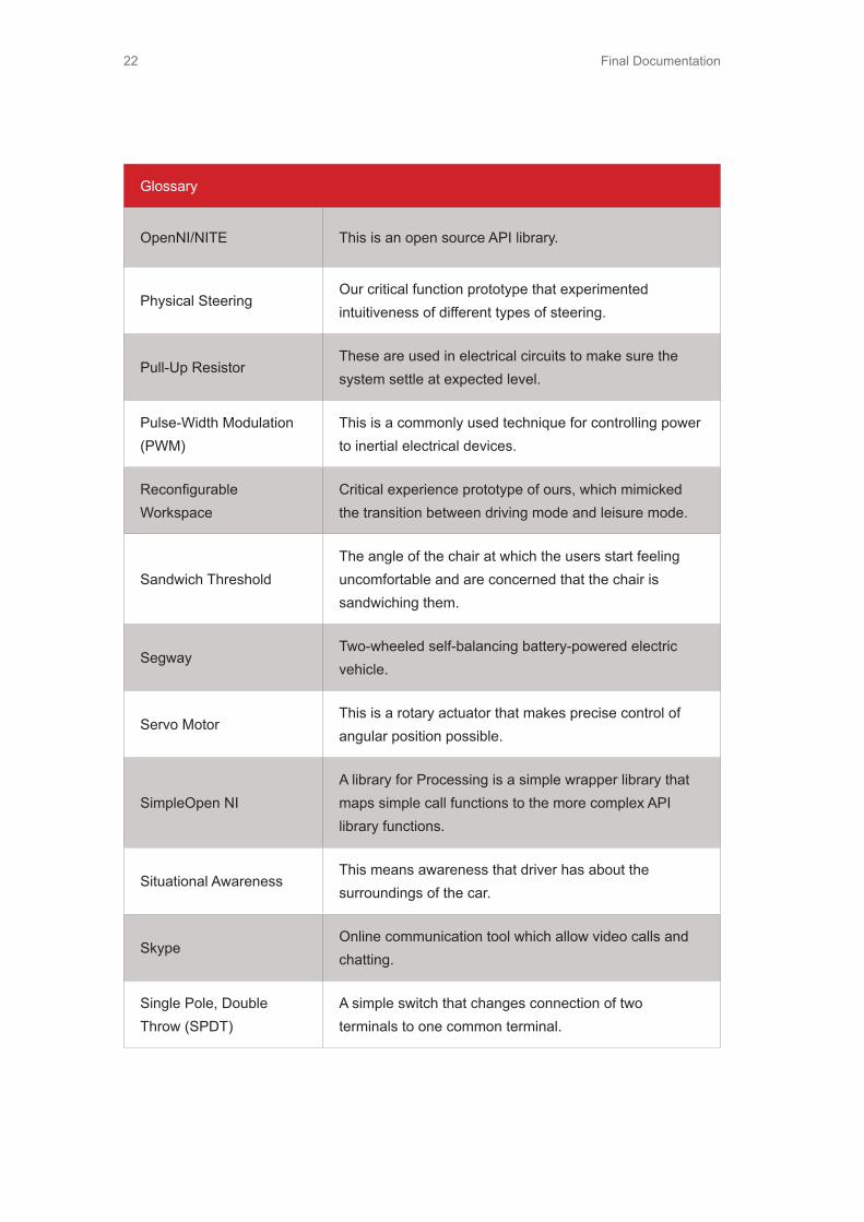
OpenNI/NITE This is an open source API library.
Physical SteeringOur critical function prototype that experimented intuitiveness of different types of steering.
Pull-Up ResistorThese are used in electrical circuits to make sure the system settle at expected level.
Pulse-Width Modulation (PWM)
This is a commonly used technique for controlling power to inertial electrical devices.
Reconfigurable Workspace
Critical experience prototype of ours, which mimicked the transition between driving mode and leisure mode.
Sandwich ThresholdThe angle of the chair at which the users start feeling uncomfortable and are concerned that the chair is sandwiching them.
SegwayTwo-wheeled self-balancing battery-powered electric vehicle.
Servo MotorThis is a rotary actuator that makes precise control of angular position possible.
SimpleOpen NIA library for Processing is a simple wrapper library that maps simple call functions to the more complex API library functions.
Situational AwarenessThis means awareness that driver has about the surroundings of the car.
SkypeOnline communication tool which allow video calls and chatting.
Single Pole, Double Throw (SPDT)
A simple switch that changes connection of two terminals to one common terminal.
Final Documentation 23
Glossary
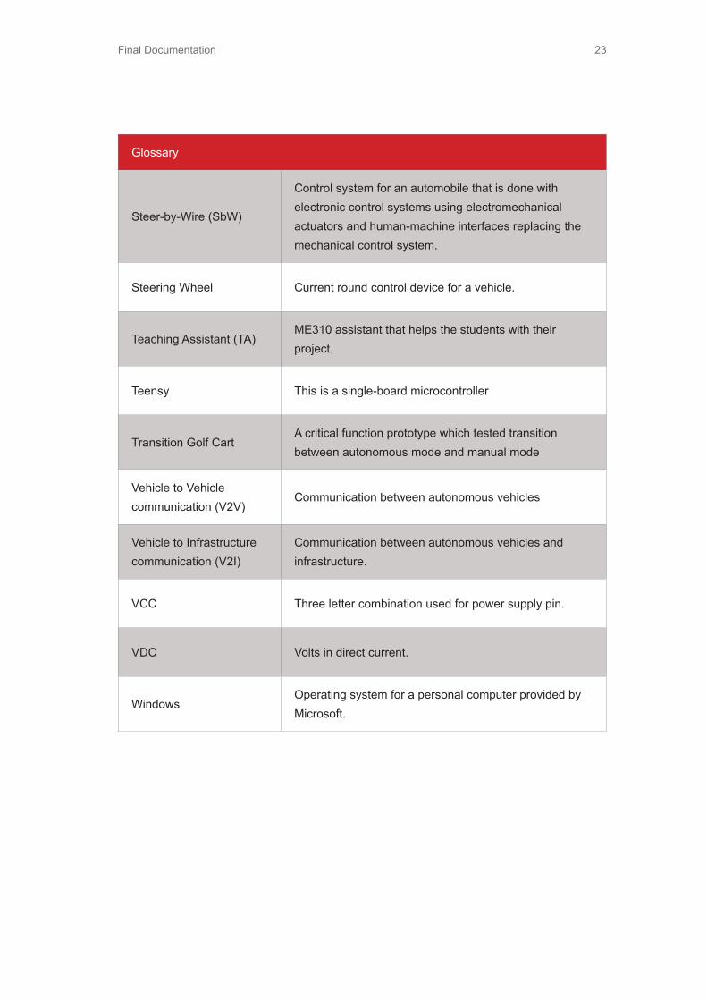
Steer-by-Wire (SbW)
Control system for an automobile that is done with electronic control systems using electromechanical actuators and human-machine interfaces replacing the mechanical control system.
Steering Wheel Current round control device for a vehicle.
Teaching Assistant (TA)ME310 assistant that helps the students with their project.
Teensy This is a single-board microcontroller
Transition Golf CartA critical function prototype which tested transition between autonomous mode and manual mode
Vehicle to Vehicle communication (V2V)
Communication between autonomous vehicles
Vehicle to Infrastructure communication (V2I)
Communication between autonomous vehicles and infrastructure.
VCC Three letter combination used for power supply pin.
VDC Volts in direct current.
WindowsOperating system for a personal computer provided by Microsoft.

Final Documentation24
Final Documentation 25
2. Context and Background

Final Documentation26
2.1 Need StatementAudi has created a brand that people respect and seek out because of their utilization of advanced technologies. They are at the forefront of innovation in automotive technology and are dedicated to providing customers with elegant, sophisticated solutions. The pursuit of new technologies and with the future always in mind, Audi has developed numerous driving assistant systems and technologies. These systems are bringing Audi one-step closer to the implementation and introduction of autonomous vehicles.
Autonomous vehicles will be relatively common by the year 2035 and Audi envisions car design will focus not only on the driving experience, but also the riding experience. As these technologies are adopted, people will want to regain time lost from commuting to locations where they would be productive. Therefore, the interior cabin space design must evolve from the current configuration meant for driving to one that is able to adapt to the various activities a driver and passenger might want to do when in autonomous driving mode.
2.2 Problem StatementThe goal of Team Audi Evolve is to develop a cabin space that will allow Audi users, in the year 2035, to perform numerous activities in an autonomous vehicle. The riding experience and driving experience of an autonomous vehicle must be considered in the solution. The cabin must be open and
adaptable in order to provide entertainment or workspace for the driver during autonomous mode, but also must provide a safe transition to manual driving when the user chooses to take over the controls. The design solution must ensure that the driver and passengers trust the vehicle’s autonomous functions. Furthermore, the solution must display all necessary information for transitioning from autonomous to manual mode and manual to autonomous mode intuitively and without being disruptive to the overall riding and driving experience. The solution must also have the sleek, sophisticated craftsmanship that the Audi brand is known for and should still retain the same look and feel of the brand.
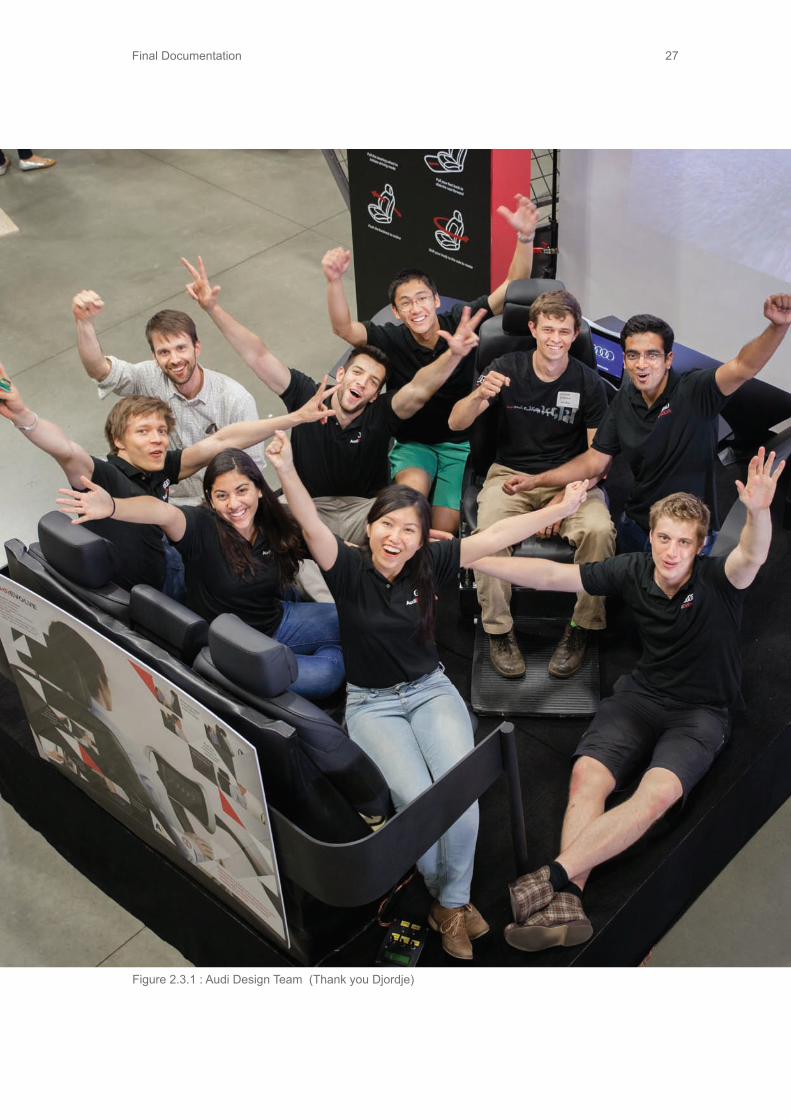
2.3 The Design TeamThe Audi 2012 design team is comprised of a diverse and multi-disciplinary group of students from Stanford University and Aalto University who are excited to be working together and learning from each other.(Figure 2.3.1: Audi Design Team)
Final Documentation 27
Figure 2.3.1 : Audi Design Team (Thank you Djordje)

Final Documentation28
2.3.1 The Stanford Team
Sangram PatilStatus: 2nd Year Mechanical Engineering Graduate StudentContact: [email protected]: 650.704.1145
After completing his undergrad in ME from India, he joined Stanford last year and has been enjoying an awesome roller-coaster ride since then. Sangram thoroughly enjoys working in team projects and being a part of a student community that is so radiant and full of enthusiasm.
Figure 2.3.1.1 : Stanford University Logo Figure 2.3.1.2 : Sangram Patil
Stanford UniversityLocation: Stanford, California (USA)Founded: 1891

Final Documentation 29
Figure 2.3.1.3 : Stephanie Tomasetta Figure 2.3.1.4 : David Wang
Stephanie TomasettaStatus: 1st Year Mechanical Engineering Graduate StudentContact: [email protected]: 732.492.8373
Stephanie received her BSE in Product Design from Stanford and decided she loved it so much she wanted to stay for a masters degree in Mechanical Engineering. She believes design can bring delight to people and hopes to design things that people will become emotionally attached to, as well as functionally.
David WangStatus: 2nd Year Electrical Engineering Graduate StudentContact: [email protected]: 407.376.4635
Born and raised in Orlando, FL. David received a BSEE from University of Florida (GO GATORS!). Interned at Lockheed Martin Missile and Fire Control in Orlando for 4 summers supporting both in-production and IRAD programs. As far as grad school, David is looking to graduate in the spring. Specialization/interest includes computer architecture, hardware design and integration.

Final Documentation30
2.3.2 The Aalto TeamFigure 2.3.2.1 : Aalto University Logo
Goran BjelajacStatus: Industrial and Strategic Design Graduate StudentContact: [email protected]: +385417009819
Goran “Goci” Bjelajac was born in 1986. in Belgrade, Serbia. Since his early age he has showed exceptional talent and interest in art. A profession in design seemed natural and the only option for him. He enrolled in specialized high-school for industrial design and has continued education at the Faculty of applied arts in Belgrade and now at Aalto University School of Art, Design and Architecture at the department of Industrial and Strategic Design.
Figure 2.3.2.2 : Goran Bjelajac
Aalto UniversityLocation: Espoo, FinlandFounded: 2010

Final Documentation 31
Sifo LuoStatus: Information and Service Management Graduate StudentContact: [email protected]: +385417009819
Sifo got her Bsc in Business Technology from Aalto School of Economics. She is now continuing her Master’s study in Information and Service Management. Educated in three countries -- China, Finland, and US, she is very good at adaptation to various cultures. Sense of urgency and teamwork are highly valued by Sifo, and her new enthusiasm is searching for inspiration in daily routine.
Figure 2.3.2.3 : Sifo Luo
Heikki SjömanStatus: Mechanical Engineering Graduate StudentContact: [email protected]: +385417009819
Heikki is on his final year of his masters degree in Mechatronics in Aalto University, Finland. During his studies, he has been working in the field of Design and spent a year in United Kingdom studying business. Heikki enjoys challenges and making things happen. Every day is a new adventure!
Figure 2.3.2.4 : Heikki Sjöman
Final Documentation32
Tommi TuulenmäkiStatus: Mechanical Engineering Graduate StudentContact: [email protected]: +385417009819
Comes from the land of ice and snow, Finland, where he did his undergrad in ME. The journey continues, and now Tommi has stepped on the path of a graduate student, which is also being done at same school, Aalto University. Tommi thinks challenges are necessary for individual development; this is why he also enjoys them so much. He rejoices even more, when overcoming the challenges is done with solid teamwork.
Figure 2.3.2.5 : Tommi Tuulenmaki
Figure 2.4.1 : Audi Logo
Figure 2.4.2 : ERL Logo
Audi is a subsidiary of the Volkswagen Group, the largest automotive vehicle manufacturer in 2011. The design team is working closely with the Electronics Research laboratory (ERL). The ERL strives to provide innovation and creativity to the Volkswagen Group and all of its brands. It is part of the global research and development network that differentiates its brands from the rest of the automotive industry through its cutting edge technology and research. The ERL performs research and development in areas such as, human machine interface systems, driver assist systems, and infotainment applications and platforms.
2.4 Corporate Sponsor

Final Documentation 33
VOLKSWAGEN Group of America, Inc.Electronics Research Laboratory500 Clipper DriveBelmont, CA 94002Phone: +1 650.496.7000
2.4.1 Corporate LiaisonTrevor ShannonVolkswagen Electronics Research LabEngineer, Multimedia Applications TeamContact: [email protected] (office): +1 650-496-7063Phone (mobile):704.340.4160
Lorenz BohrerUser Interaction designerContact: [email protected] (office): +49 849 89 576866
2.5 Teaching TeamStanford UniversityMark Cutkosky, ProfessorContact: [email protected]
Larry Leifer, ProfessorContact: [email protected]
George Toye, ProfessorContact: [email protected]
Tyler Bushnell, Teaching AssistantContact: [email protected]
Annika Matta, Teaching AssistantContact: [email protected]
Scott Steber, Teaching AssistantContact: [email protected]
Jeremy Dabrowiak, CoachContact: [email protected]: 650.274.7871
Lauri Repokari, ProfessorContact: [email protected]
Sara De Moitie, Teaching AssistantContact: [email protected]
Maria Kulse, Teaching AssistantContact: [email protected]
Tuomas Sahramaa, Teaching AssistantContact: [email protected]
Mikelis Studers, Teaching AssistantContact: [email protected]
Harri Toivonen, Teaching AssistantContact: [email protected]
Markku Kokela, Teaching AssistantContact: [email protected]
Lassi Laitinen, CoachContact: [email protected]
2.6 Special Thanks toGeorge Atanasov, Marko Takala, Jordan Davidson, Benjamin Tee
Final Documentation34
Figure 2.5.1 : Aalto Teaching Team

Final Documentation 35
3. Design Requirements

Final Documentation36
3.1 Given RequirementsBased on the benchmarking, needfinding and prototyping that was carried out in the last six months, the team identified certain basic functional and physical requirements that the final solution should address. The team also identified many interesting directions and opportunities, which can be explored while working towards a design
Design Requirement Rationale
Driver should trust car’s autonomous functionsIn order for the driver to fully enjoy autonomous mode of the car, he/she should have complete confidence in it’s control
Smooth and comfortable transitions between modes and activities
The driver will perform a lot of activities in autonomous mode and will need to transition between them quickly and easily.
Cabin should be clear and open
In order to appreciate freedom inside of the car, cabin has to be spacious enough and clear so it provides comfortable working environment.
Audi “fit and finish”The solution should have a similar level of quality and usability as all Audi cars
solution. The functional requirements listed in this section dictate what the system must do and what functionality should be provided by the solution. The physical requirements dictate what the system should be like physically. Given requirements have been listed based on the abstract that has been provided. These requirements have either been expanded and/or refined further based on the testing done this quarter.
Table 3.1.1 : Given Design Requirements

Final Documentation 37
3.2 Functional RequirementsFu
nctio
nal
Req
uire
men
tsM
etric
Rat
iona
leIm
plem
enta
tion
The
inte
rface
for
reco
nfigu
ratio
n of
the
cabi
n sp
ace
shou
ld b
e in
tuiti
ve to
the
user
.
Afte
r ne
w u
sers
go
thro
ugh
the
vario
us
inte
ract
ions
w
ith
the
reco
nfigu
ratio
n in
terfa
ce 3
tim
es,
they
sho
uld
be c
omfo
rtabl
e us
ing
it at
any
poi
nt la
ter.
The
team
wan
ts to
targ
et a
co
mfo
rtabl
e tra
nsiti
on b
etw
een
activ
ities
. For
this
goa
l to
be
achi
eved
the
inte
rface
for t
his
trans
ition
whi
ch w
ill re
confi
gure
th
e ca
bin
spac
e ne
eds
to b
lend
in
with
the
trans
ition
itse
lf.
This
requ
irem
ent i
s ac
hiev
ed
thro
ugh
havi
ng a
tabl
et th
at h
as
an a
udib
le c
lick
whe
n m
ode
has
been
cha
nged
, and
an
easy
-to-
lear
n in
tera
ctio
n w
ith th
e ch
air.
The
driv
er w
ill re
ceiv
e cl
ear
confi
rmat
ion
on w
hich
mod
e he
/sh
e is
on.
The
inte
rface
us
ed s
houl
d in
dica
te to
the
user
that
the
trans
ition
is
com
plet
e.
Ther
e sh
ould
be
100%
aw
aren
ess
amon
gst t
he u
sers
in te
rms
of th
e cu
rrent
mod
e of
the
confi
gura
tion
at a
ll tim
es d
urin
g tra
nsiti
on.
If as
ked
abou
t the
cur
rent
mod
e at
an
y po
int
durin
g tra
nsiti
on,
the
user
sho
uld
be a
ble
to id
entif
y it
corre
ctly
at a
ny ti
me.
This
is re
quire
d fo
r use
r acc
epta
bility
an
d co
mfo
rt du
ring
the
trans
ition
. Be
ing
kept
aw
are
of t
he c
urre
nt
mod
e of
the
car w
ill al
so le
ad to
a
reas
sura
nce
of tr
ust o
n th
e sy
stem
.
The
tabl
et
has
two
diffe
rent
in
terfa
ces
for
two
diffe
rent
mod
es.
In a
uton
omou
s m
ode,
the
inte
rface
is
a u
nloc
ked
so it
can
be
used
as
an
inpu
t dev
ice
for w
orki
ng; i
n m
anua
l m
ode,
th
e in
terfa
ce
is
lock
ed,
show
ing
an im
age
of th
e Au
di lo
go.
The
cabi
n sp
ace
shou
ld h
ave
the
flexi
bilit
y of
m
ovin
g ar
ound
The
user
sho
uld
be a
ble
to tu
rn
and
be c
omfo
rtabl
e at
any
ang
le
or o
rient
atio
n. T
he d
esig
n sh
ould
al
low
the
user
to m
ove
a di
stan
ce
whi
ch is
at l
east
2 ti
mes
the
wid
th
of th
e se
atin
g or
cha
ir
Not
all a
ctiv
ities
that
the
user
wou
ld
wan
t to pe
rform
whe
n in a
uton
omou
s m
ode
can
be p
erfo
rmed
whi
le b
eing
in
the
driv
ing
posi
tion.
The
rota
tion
mec
hani
sm w
ithin
the
chai
r allo
ws
the
driv
er to
hav
e m
uch
mor
e m
obilit
y an
d be
abl
e to
mov
e an
d si
t in
any
orie
ntat
ion.
Table 3.2.1 : Functional Requirements Part1

Final Documentation38
Table 3.2.1 : Functional Requirements Part2
Func
tiona
l R
equi
rem
ents
Met
ricR
atio
nale
Impl
emen
tatio
n
Cab
in h
as to
be
wel
l sui
ted
for
perfo
rmin
g th
e m
ultip
le a
ctiv
ities
in
aut
onom
ous
mod
e
Ther
e sh
ould
be
at le
ast 5
di
ffere
nt a
ctiv
ities
that
can
ea
sily
be
perfo
rmed
in th
e ca
bin
spac
e th
roug
h m
inim
al c
abin
ch
ange
s.
This
is fo
r dev
elop
ing
an
adap
tabl
e ca
bin
spac
e th
at a
llow
s fo
r pas
seng
ers
to u
se th
e sp
ace
for a
num
ber o
f diff
eren
t act
iviti
es
sinc
e in
aut
onom
ous
mod
e th
ey
will
have
free
tim
e to
do
thin
gs
othe
r tha
n dr
ive.
The
cabi
n al
low
s th
e dr
iver
to
per
form
var
ious
act
iviti
es
thro
ugh
the
tabl
et in
terfa
ce; t
he
chai
r brin
gs m
ore
flexi
bilit
y an
d im
prov
ed s
ocia
lizat
ion
thro
ugh
F2F
inte
ract
ion
with
bac
ksea
t pa
ssen
gers
.
Ther
e sh
ould
be
max
imum
ut
ilizat
ion
of
cabi
n sp
ace
arou
nd th
e dr
iver
volu
met
ric
The
cabi
n sp
ace
shou
ld n
o lo
nger
fe
el li
ke a
tigh
t tra
nspo
rtatio
n ve
hicl
e an
d in
stea
d ne
eds
to b
e m
ore
spac
ious
like
a ro
om in
a
hom
e.
By re
mov
ing
the
front
pas
seng
er
seat
, the
cab
in s
pace
is n
ow m
ore
free
and
spac
ious
.
Smoo
th a
nd
com
forta
ble
trans
ition
s be
twee
n m
odes
an
d ac
tiviti
es
The
cont
rolle
r mus
t be
able
to
perfo
rm a
t lea
st 5
act
iviti
es th
at
wou
ld w
ant t
o be
per
form
ed in
th
e ve
hicl
e, in
clud
ing
driv
ing.
It m
akes
sen
se to
pro
vide
m
axim
um fu
nctio
nalit
y w
ith
min
imum
clu
tter i
n te
rms
of th
e co
ntro
ls.
The
mod
e tri
gger
on
the
stee
ring
whe
el d
one
by p
ushi
ng a
nd p
ullin
g is
pro
ven
easy
and
intu
itive
for
user
to p
erfo
rm in
any
mod
e. T
he
chai
r is
an a
dapt
ive
inte
ract
ion
whi
ch re
mov
es th
e ne
ed fo
r te
diou
s m
anua
l adj
ustm
ents
and
al
low
s th
e us
er to
nat
ural
ly fl
ow
into
the
next
act
iviti
es p
ositi
on.

Final Documentation 39
Table 3.2.1 : Functional Requirements Part3
Func
tiona
l R
equi
rem
ents
Met
ricR
atio
nale
Impl
emen
tatio
n
Qui
ck tr
ansi
tions
be
twee
n m
odes
an
d ac
tiviti
es
The
time
it ta
kes
to b
egin
the
next
act
ivity
is le
ss th
an 1
5 se
cond
s
The
smar
t cab
in s
pace
aim
s at
redu
cing
the
tedi
ous
task
s as
soci
ated
with
man
ually
re
confi
gurin
g th
e sp
ace
ever
y tim
e th
e us
er w
ants
to d
o a
diffe
rent
act
ivity
The
chai
r mec
hani
sm is
des
igne
d to
rota
te a
t a c
omfo
rtabl
e sp
eed
to
quic
kly
mov
e th
e dr
iver
into
thei
r ne
xt p
ositi
on.T
he s
teer
ing
whe
el
retra
ctio
n m
echa
nism
is fa
st to
ac
tivat
e.
Con
trol i
nput
de
sign
sho
uld
mai
ntai
n th
e pr
ecis
e co
ntro
l an
d sp
orty
fe
elin
g of
driv
ing
an A
udi
A re
spon
sibl
e dr
iver
sho
uld
scor
e th
e co
ntro
l inp
ut re
spon
se
to b
e 7
or h
ighe
r on
a sc
ale
of
10 th
at m
easu
res
the
spor
ty
feel
ing
of a
n Au
di c
ontro
l inp
ut
This
is a
n es
sent
ial r
equi
rem
ent
for c
ars
of th
e fu
ture
, whe
re
man
ual d
rivin
g ha
s be
en
rede
fined
due
to th
e ad
ded
cras
h pr
oof s
yste
ms,
whi
ch w
ill al
way
s be
act
ive
for s
afet
y. A
n im
porta
nt
fact
or c
ontri
butin
g to
the
plea
sure
of
driv
ing
is th
e fe
elin
g an
d th
rill
of c
ontro
lling
a co
mpl
ex m
achi
ne
incr
ease
s th
e sp
orty
feel
ing,
whi
le
the
cent
ered
pos
ition
of t
he c
hair
mim
ics
the
setu
p of
a fo
rmul
a ra
ce
car t
o fu
rther
enh
ance
a s
porty
dr
ivin
g ex
perie
nce.
Rel
ieve
s th
e dr
iver
of t
he
resp
onsi
bilit
y of
mon
itorin
g au
tono
mou
s dr
ivin
g
Use
r che
cks
or v
erifi
es th
e ca
r in
form
atio
n no
t mor
e th
an o
nce
in e
very
3 m
inut
es
Red
ucin
g th
e di
stra
ctio
n du
e to
th
e au
tono
mou
s co
ntro
ller a
ctio
ns
will
help
use
rs fo
cus
bette
r on
and
enjo
y do
ing
othe
r act
iviti
es.
The
stee
ring
whe
el c
an n
ot m
ove
in a
uton
omou
s m
ode
and
can
be
used
for c
ontro
lling
wor
k co
nten
ts
on th
e w
inds
hiel
d.
Final Documentation40
Func
tiona
l R
equi
rem
ents
Met
ricR
atio
nale
Impl
emen
tatio
n
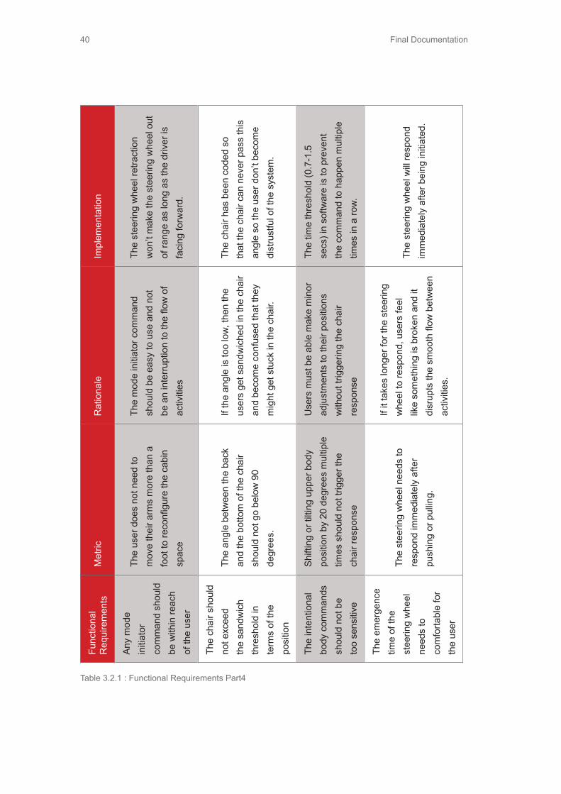
Any
mod
e in
itiat
or
com
man
d sh
ould
be
with
in re
ach
of th
e us
er
The
user
doe
s no
t nee
d to
m
ove
thei
r arm
s m
ore
than
a
foot
to re
confi
gure
the
cabi
n sp
ace
The
mod
e in
itiat
or c
omm
and
shou
ld b
e ea
sy to
use
and
not
be
an
inte
rrupt
ion
to th
e flo
w o
f ac
tiviti
es
The
stee
ring
whe
el re
tract
ion
won
’t m
ake
the
stee
ring
whe
el o
ut
of ra
nge
as lo
ng a
s th
e dr
iver
is
faci
ng fo
rwar
d.
The
chai
r sho
uld
not e
xcee
d th
e sa
ndw
ich
thre
shol
d in
te
rms
of th
e po
sitio
n
The
angl
e be
twee
n th
e ba
ck
and
the
botto
m o
f the
cha
ir sh
ould
not
go
belo
w 9
0 de
gree
s.
If th
e an
gle
is to
o lo
w, th
en th
e us
ers
get s
andw
iche
d in
the
chai
r an
d be
com
e co
nfus
ed th
at th
ey
mig
ht g
et s
tuck
in th
e ch
air.
The
chai
r has
bee
n co
ded
so
that
the
chai
r can
nev
er p
ass
this
an
gle
so th
e us
er d
on’t
beco
me
dist
rust
ful o
f the
sys
tem
.
The
inte
ntio
nal
body
com
man
ds
shou
ld n
ot b
e to
o se
nsiti
ve
Shift
ing
or ti
lting
upp
er b
ody
posi
tion
by 2
0 de
gree
s m
ultip
le
times
sho
uld
not t
rigge
r the
ch
air r
espo
nse
Use
rs m
ust b
e ab
le m
ake
min
or
adju
stm
ents
to th
eir p
ositi
ons
with
out t
rigge
ring
the
chai
r re
spon
se
The
time
thre
shol
d (0
.7-1
.5
secs
) in
softw
are
is to
pre
vent
th
e co
mm
and
to h
appe
n m
ultip
le
times
in a
row.
The
emer
genc
e tim
e of
the
stee
ring
whe
el
need
s to
co
mfo
rtabl
e fo
r th
e us
er
The
stee
ring
whe
el n
eeds
to
resp
ond
imm
edia
tely
afte
r pu
shin
g or
pul
ling.
If it
take
s lo
nger
for t
he s
teer
ing
whe
el to
resp
ond,
use
rs fe
el
like
som
ethi
ng is
bro
ken
and
it di
srup
ts th
e sm
ooth
flow
bet
wee
n ac
tiviti
es.
The
stee
ring
whe
el w
ill re
spon
d im
med
iate
ly a
fter b
eing
initi
ated
.
Table 3.2.1 : Functional Requirements Part4

Final Documentation 41
Func
tiona
l R
equi
rem
ents
Met
ricR
atio
nale
Impl
emen
tatio
n
The
emer
genc
e tim
e of
the
stee
ring
whe
el
need
s to
co
mfo
rtabl
e fo
r th
e us
er
The
chai
r sho
uld
be a
ble
to n
ot
only
rota
te fu
lly b
ack
but a
lso
mov
e ba
ckw
ard
and
forw
ard.
The
driv
er s
houl
d be
abl
e to
ro
tate
bac
k an
d m
ove
clos
er to
ba
ckse
at to
ach
ieve
bet
ter F
2F
com
mun
icat
ion
with
bac
k se
at
pass
enge
rs. W
hen
driv
ing,
the
driv
er s
houl
d be
fit i
nto
the
best
dr
ivin
g po
sitio
n.
The
chai
r can
rota
te 1
80 d
egre
es
to th
e ba
ck a
nd th
e di
stan
ce
btw
foot
pad
and
the
back
seat
pa
ssen
gers
is 4
0 in
ches
, so
that
a
com
forta
ble
com
mun
icat
ion
envi
ronm
ent i
s m
aint
aine
d.
Smar
t fea
ture
s m
ust b
e tu
rned
of
f whe
n in
m
anua
l driv
ing
mod
e.
The
chai
r sho
uld
not b
e ab
le
to b
e m
oved
or a
ctiv
ated
with
sm
art f
eatu
res
in m
anua
l mod
e.
The
driv
er s
houl
dn’t
be ro
tate
d du
ring
man
ual d
rivin
g m
ode
no
mat
ter w
hat b
ody
mov
emen
t he
/she
per
form
s as
it w
ould
be
unsa
fe.
The
chai
r is
code
d so
that
whe
n th
e m
anua
l mod
e is
sta
rted
the
chai
r’s s
mar
t fea
ture
s ar
e di
sabl
ed.
Table 3.2.1 : Functional Requirements Part5

Final Documentation42
Table 3.2.1.1 : Functional Opportunities
3.2.1 Functional Opportunities
Opp
ortu
nity
Rat
iona
leIm
plem
enta
tion
Usin
g th
e w
inds
hiel
d as
an
inte
ract
ive
surfa
ce
Sin
ce t
he u
sers
are
not
driv
ing
anym
ore,
th
e w
inds
hiel
d ca
n be
use
d to
inte
ract
with
m
ultim
edia
whi
le in
aut
onom
ous
mod
e.
In o
ur c
once
pt, s
peed
omet
er a
nd d
rivin
g in
fo w
ill be
sho
wn
on th
e w
inds
hiel
d as
AR
co
nten
ts in
man
ual d
rivin
g m
ode,
and
in
auto
nom
ous
mod
e w
inds
hiel
d w
ill be
use
d as
wor
king
inte
rface
.
Shou
ld b
e ab
le to
reco
gnize
driv
er
pref
eren
ces
with
out a
ny in
put f
rom
the
drive
r
This
is e
spec
ially
app
licab
le in
car
sha
ring
scen
ario
s w
here
diff
eren
t driv
ers
wou
ld b
e us
ing
the
sam
e ca
r. Th
e ca
bin
spac
e ne
eds
to b
e sm
art e
noug
h to
read
just
acc
ordi
ng to
th
e us
er.
It co
uld
be p
ossi
ble
for t
he c
ar to
beg
in to
re
cogn
ize
diffe
rent
def
ault
sitti
ng p
ositi
ons
and
adju
st a
ll set
tings
to th
at s
peci
fied
user
.
Cab
in s
houl
d be
abl
e to
inte
grat
e ne
w
tech
nolo
gies
qui
ckly
This
is
to b
e in
lin
e w
ith t
he f
ast
pace
d te
chno
logy
dev
elop
men
t in
the
fut
ure
and
Aud
i’s g
oal t
o pr
ovid
e th
eir
cust
omer
s w
ith
the
late
st te
chno
logi
cal s
olut
ions
in th
eir c
ars.
It
can
even
be
an u
pgra
de b
ased
bus
ines
s m
odel
like
the
curre
nt s
mar
t pho
nes.
For e
xam
ple:
AR
win
dshi
eld

Final Documentation 43
Table 3.3.1 : Physical Requirements
Phys
ical
Req
uire
-m
ents
Met
ricR
atio
nale
Impl
emen
tatio
n
The
cabi
n sp
ace
shou
ld
be o
pen
and
clear
Whe
n al
l in
tegr
ated
fe
atur
es a
re s
tow
ed a
way
, fo
ur p
asse
nger
s m
ust b
e ab
le t
o st
retc
h th
eir
legs
ou
t with
out h
ittin
g an
ythi
ng.
The
cabi
n sp
ace
mus
t be
open
and
m
ore
com
forta
ble
in o
rder
for p
eopl
e to
hav
e th
e ro
om to
be
able
to w
ork,
re
lax,
or s
ocia
lize.
Ther
e ar
e se
ats
for t
hree
pas
seng
ers
in th
e ba
ckse
at a
s w
ell a
s th
e dr
iver
. Th
e ca
bin
is m
uch
mor
e op
en d
ue to
th
e re
mov
al o
f th
e fro
nt p
asse
nger
se
at.
The
desi
gned
con
trol
inpu
ts s
houl
d m
aint
ain
the
plea
sure
of d
rivin
g an
d be
com
forta
ble
to
use
Driv
er
mus
t ex
perie
nce
hapt
ic fe
edba
ck f
rom
the
co
ntro
l inpu
t whe
n in
driv
ing
mod
e th
at th
ey d
eem
to b
e re
al (8
out
of 1
0 on
a p
ost
test
ing
surv
ey),
in o
rder
to
mai
ntai
n fe
elin
g th
eir c
ontro
l of
the
car o
n th
e ro
ad.
The
driv
ing
cont
rol i
nput
s m
ay n
ot
long
er n
eed
to b
e pr
ecis
e. I
nste
ad,
they
sho
uld
be e
asy
to u
se a
nd fu
n si
nce
driv
ing
is a
n ac
tivity
the
driv
er
will
wan
t to
do, n
ot h
ave
to d
o.
The
fit a
nd fi
nish
of t
he
desi
gn m
ust b
e in
line
w
ith b
rand
AU
DI
Car
ent
husi
asts
mus
t be
ab
le to
iden
tify
Audi
as
the
prot
otyp
e’s
man
ufac
ture
r w
ith 8
5% a
ccur
acy.
Use
rs a
re b
rand
loy
al a
nd p
art
of
Aud
i’s b
rand
is it
s re
finem
ent
and
soph
istic
atio
n ac
hiev
ed th
roug
h th
eir
fine
styl
ing.
The
refo
re,
the
fit a
nd
finis
h of
the
desi
gn m
ust a
lign
with
Au
di’s
in o
rder
to b
e co
nsis
tent
and
ap
peal
ing
to th
e Au
di u
ser.
The
aest
hetic
s fit
into
wha
t the
team
be
lieve
s Au
di w
ill lo
ok li
ke in
the
year
20
35.
The
col
or s
chem
e re
mai
ns tr
ue
to th
e Au
di tr
aditi
on.
3.3 Physical Requirements
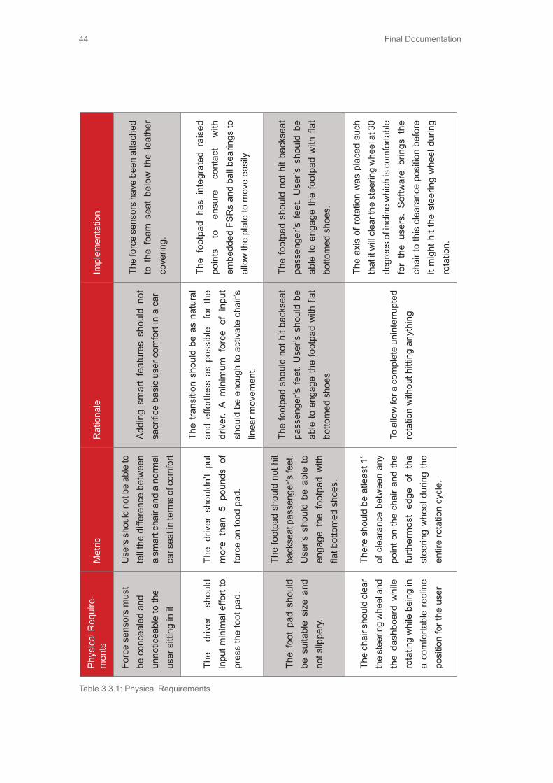
Final Documentation44
Table 3.3.1: Physical Requirements
Phys
ical
Req
uire
-m
ents
Met
ricR
atio
nale
Impl
emen
tatio
n
Forc
e se
nsor
s m
ust
be c
once
aled
and
un
notic
eabl
e to
the
user
sitt
ing
in it
Use
rs s
houl
d no
t be
able
to
tell
the
diffe
renc
e be
twee
n a
smar
t cha
ir an
d a
norm
al
car s
eat i
n te
rms
of c
omfo
rt
Add
ing
smar
t fe
atur
es s
houl
d no
t sa
crifi
ce b
asic
use
r com
fort
in a
car
The
forc
e se
nsor
s ha
ve b
een
atta
ched
to
the
foa
m s
eat
belo
w t
he l
eath
er
cove
ring.
The
driv
er
shou
ld
inpu
t min
imal
effo
rt to
pr
ess
the
foot
pad
.
The
driv
er s
houl
dn’t
put
mor
e th
an 5
pou
nds
of
forc
e on
food
pad
.
The
trans
ition
sho
uld
be a
s na
tura
l an
d ef
fortl
ess
as p
ossi
ble
for
the
dr
iver
. A
min
imum
for
ce o
f in
put
shou
ld b
e en
ough
to a
ctiv
ate
chai
r’s
linea
r mov
emen
t.
The
foot
pad
has
inte
grat
ed r
aise
d po
ints
to
en
sure
co
ntac
t w
ith
embe
dded
FSR
s an
d ba
ll be
arin
gs to
al
low
the
plat
e to
mov
e ea
sily
The
foot
pad
sho
uld
be s
uita
ble
size
and
no
t slip
pery
.
The
foot
pad
shou
ld n
ot h
it ba
ckse
at p
asse
nger
’s fe
et.
Use
r’s s
houl
d be
abl
e to
en
gage
the
foo
tpad
with
fla
t bot
tom
ed s
hoes
.
The
foot
pad
shou
ld n
ot h
it ba
ckse
at
pass
enge
r’s fe
et. U
ser’s
sho
uld
be
able
to e
ngag
e th
e fo
otpa
d w
ith fl
at
botto
med
sho
es.
The
foot
pad
shou
ld n
ot h
it ba
ckse
at
pass
enge
r’s f
eet.
Use
r’s s
houl
d be
ab
le to
eng
age
the
foot
pad
with
flat
bo
ttom
ed s
hoes
.
The
chai
r sho
uld
clea
r th
e st
eerin
g w
heel
and
th
e da
shbo
ard
whi
le
rota
ting
whi
le b
eing
in
a co
mfo
rtabl
e re
clin
e po
sitio
n fo
r the
use
r
Ther
e sh
ould
be
atle
ast 1
” of
cle
aran
ce b
etw
een
any
poin
t on
the
chai
r and
the
furth
erm
ost
edge
of
the
stee
ring
whe
el d
urin
g th
e en
tire
rota
tion
cycl
e.
To a
llow
for a
com
plet
e un
inte
rrupt
ed
rota
tion
with
out h
ittin
g an
ythi
ng
The
axis
of r
otat
ion
was
pla
ced
such
th
at it
will
clea
r the
ste
erin
g w
heel
at 3
0 de
gree
s of
incl
ine
whi
ch is
com
forta
ble
for
the
user
s. S
oftw
are
brin
gs t
he
chai
r to
this
cle
aran
ce p
ositi
on b
efor
e it
mig
ht h
it th
e st
eerin
g w
heel
dur
ing
rota
tion.

Final Documentation 45
Phys
ical
Req
uire
-m
ents
Met
ricR
atio
nale
Impl
emen
tatio
n
Forc
e se
nsor
s m
ust
be c
once
aled
and
un
notic
eabl
e to
the
user
sitt
ing
in it
Use
rs s
houl
d no
t be
able
to
tell
the
diffe
renc
e be
twee
n a
smar
t cha
ir an
d a
norm
al
car s
eat i
n te
rms
of c
omfo
rt
Add
ing
smar
t fe
atur
es s
houl
d no
t sa
crifi
ce b
asic
use
r com
fort
in a
car
The
forc
e se
nsor
s ha
ve b
een
atta
ched
to
the
foa
m s
eat
belo
w t
he l
eath
er
cove
ring.
The
driv
er
shou
ld
inpu
t min
imal
effo
rt to
pr
ess
the
foot
pad
.
The
driv
er s
houl
dn’t
put
mor
e th
an 5
pou
nds
of
forc
e on
food
pad
.
The
trans
ition
sho
uld
be a
s na
tura
l an
d ef
fortl
ess
as p
ossi
ble
for
the
dr
iver
. A
min
imum
for
ce o
f in
put
shou
ld b
e en
ough
to a
ctiv
ate
chai
r’s
linea
r mov
emen
t.
The
foot
pad
has
inte
grat
ed r
aise
d po
ints
to
en
sure
co
ntac
t w
ith
embe
dded
FSR
s an
d ba
ll be
arin
gs to
al
low
the
plat
e to
mov
e ea
sily
The
foot
pad
sho
uld
be s
uita
ble
size
and
no
t slip
pery
.
The
foot
pad
shou
ld n
ot h
it ba
ckse
at p
asse
nger
’s fe
et.
Use
r’s s
houl
d be
abl
e to
en
gage
the
foo
tpad
with
fla
t bot
tom
ed s
hoes
.
The
foot
pad
shou
ld n
ot h
it ba
ckse
at
pass
enge
r’s fe
et. U
ser’s
sho
uld
be
able
to e
ngag
e th
e fo
otpa
d w
ith fl
at
botto
med
sho
es.
The
foot
pad
shou
ld n
ot h
it ba
ckse
at
pass
enge
r’s f
eet.
Use
r’s s
houl
d be
ab
le to
eng
age
the
foot
pad
with
flat
bo
ttom
ed s
hoes
.
The
chai
r sho
uld
clea
r th
e st
eerin
g w
heel
and
th
e da
shbo
ard
whi
le
rota
ting
whi
le b
eing
in
a co
mfo
rtabl
e re
clin
e po
sitio
n fo
r the
use
r
Ther
e sh
ould
be
atle
ast 1
” of
cle
aran
ce b
etw
een
any
poin
t on
the
chai
r and
the
furth
erm
ost
edge
of
the
stee
ring
whe
el d
urin
g th
e en
tire
rota
tion
cycl
e.
To a
llow
for a
com
plet
e un
inte
rrupt
ed
rota
tion
with
out h
ittin
g an
ythi
ng
The
axis
of r
otat
ion
was
pla
ced
such
th
at it
will
clea
r the
ste
erin
g w
heel
at 3
0 de
gree
s of
incl
ine
whi
ch is
com
forta
ble
for
the
user
s. S
oftw
are
brin
gs t
he
chai
r to
this
cle
aran
ce p
ositi
on b
efor
e it
mig
ht h
it th
e st
eerin
g w
heel
dur
ing
rota
tion.
Opp
ortu
nity
Rat
iona
leIm
plem
enta
tion
Red
esig
ning
the
car
stru
ctur
e its
elf
This
opp
ortu
nity
allo
ws
for m
ore
flexi
bilit
y fo
r the
cab
in s
pace
with
out
bein
g co
nstra
ined
to th
e in
tern
al s
truct
ure
of c
urre
nt c
ars
The
prot
otyp
e is
bui
lt on
a p
latfo
rm
in o
rder
to
inco
rpor
ate
the
new
ro
tatio
n fe
atur
e an
d no
t be
rest
ricte
d by
the
curre
nt c
ar c
onst
rain
ts.
Hav
ing
the
car s
pace
as
a p
art o
f the
use
r’s
hom
e
If th
ere
is p
erso
nal o
wne
rshi
p of
the
car
in th
e fu
ture
and
the
cabi
n sp
ace
has
been
so
wel
l des
igne
d it
mig
ht a
s w
ell i
nteg
rate
into
the
hom
e sp
ace
inst
ead
of b
eing
par
ked
away
in a
gar
age
Tran
sfor
mer
car
The
car
trans
form
s in
to a
per
sona
l rob
ot to
bet
ter
inte
grat
e in
to th
e liv
es o
f peo
ple
Expl
orin
g th
e op
tions
of
us
ing
Virtu
al
Rea
lity in
the
cabi
n sp
ace
VR te
chno
logy
wou
ld p
roba
bly
be s
o w
ell d
evel
oped
in th
e fu
ture
that
it
mig
ht n
ot b
e ne
cess
ary
to h
ave
the
com
plet
e fu
nctio
nalit
y in
the
cabi
n sp
ace.
One
dire
ctio
n of
the
solu
tion
mig
ht ju
st b
e to
hav
e a
virtu
al
real
ity h
elm
et a
nd tr
ansp
ort t
he u
sers
whe
reve
r the
y w
ant t
o be
. Thi
s go
es b
eyon
d th
e co
nstra
ints
of c
abin
spa
ces.
3.3.1 Physical Opportunities
Table 3.3.1.1: Physical Opportunities

Final Documentation46
Opp
ortu
nity
Rat
iona
leIm
plem
enta
tion
Com
bini
ng b
oth
the
stee
ring
and
peda
ls
into
a m
ore
intu
itive
co
ntro
l inp
ut
Des
igni
ng a
new
con
trol in
put l
ike
this
has
the
pote
ntia
l to
mak
e dr
ivin
g m
ore
fun
whi
le b
eing
eas
ier t
o tra
nsiti
on to
.
Util
izin
g w
alls
and
w
indo
ws
insi
de
the
cabi
n sp
ace
as
inte
ract
ive
inpu
ts
This
is o
ne d
irect
ion,
whi
ch c
an b
e ex
plor
ed fo
r max
imum
util
izat
ion
of c
abin
spa
ce.
This
is
cu
rren
tly
only
be
ing
impl
emen
ted
on th
e w
inds
hiel
d of
th
e ca
r.
The
cabi
n sp
ace
shou
ld
be
reco
nfigu
rabl
e
The
cabi
n m
ust h
ave
inte
grat
ed ta
bles
and
sto
rage
that
are
sto
wed
aw
ay, b
ut s
till w
ithin
the
user
’s re
ach
(2.5
ft) a
t any
cha
ir lo
catio
n.
The
cabi
n w
ill be
use
d fo
r va
rious
ac
tiviti
es s
o us
ers
may
wan
t to
re
arra
nge,
and
intro
duce
or
stow
aw
ay it
ems
in th
e sp
ace
to b
e be
tter
suite
d fo
r tha
t act
ivity
.
Table 3.3.1.1.: Physical Opportunities Part 2

Final Documentation 47
3.4 Business OpportunityOpportunity Rationale
New business model for AUDI
After the launch of autonomous cars, the business model can shift to car sharing or a subscription based model which will redefine ownership of cars and urban mobility in the future in general.
Table 3.4.1 : Business Opportunity

Final Documentation48

Final Documentation 49
4. Design Development
Final Documentation50
Audi is a subsidiary of the Volkswagen Group, the largest automotive vehicle manufacturer in 2011. The design team is working closely with the Electronics Research laboratory (ERL). The ERL strives to provide innovation and creativity to the Volkswagen Group and all of its brands. It is part of the global research and development network that differentiates its brands from the rest of the automotive industry through its cutting edge technology and research. The ERL performs research and development in areas such as, human machine interface systems, driver assist systems, and infotainment applications and platforms.
4.1 Future AssumptionsAssumptions help the team to build a picture of what the world will be in the future. In order to get a feasible frame for the design work, especially when it involved designing something so far in the future, the team made reasonable assumptions based on basic trends from the past to present, research, needfinding and benchmarking. Sources for these iterations can be found among appendices.
4.1.1 Future UserThe current generation has grown up in the “technology revolution”. People are use to the fast paced development in technology and the effect of these new technologies on our lives is continually growing. Smartphones and smart handheld devices have redefined the way we interact with digital media. If smart and self-aware cars
of the future are well integrated in the lives of users, the team can envision that people would show the same enthusiasm towards these autonomous machines and new upcoming technology as they are currently showing towards smartphones.
Internet and social networks have surpassed boundaries of countries in terms of connecting people across distant areas of the world. Accessing a wide range of information has never been this easy and it is going to get better in the future. There is this concept of “perpetual connectivity” which is being predicted for the future. It is only a matter of time before all the existing technologies are developed to such an extent that they become a part of our lives and blend in so well that we cannot do without them. Specifically in terms of automotive experiences, it is already being seen that the current generation views driving as a distraction from texting rather than the other way around. Since being connected is so easy, people want to stay connected. This does not mean that the future users would not love driving.
Experiencing moments of thrill and adventure would still be desirable in the future, but the essential difference would lie in doing things because users want to do them rather than spending time being forced to do them. It is an extrapolation of the current scenario when people are forced to drive along freeways with all the traffic only because they have to travel to and from work everyday. Based on this insight,

Final Documentation 51
it is highly probable that users will find it desirable to have an option to ride in a cabin space that is customized to their needs and the activities that they would want to do, to better utilize this time lost in commuting.
The internet age has also led to more liberal thinking. Non-conventional work options are being explored. It has been envisioned that new technology will lead to a great shift in working spaces, work cultures and procedures. The future users are most likely going to work in an environment where physical presence is no longer required on a daily basis. In such a situation and with the increasing influence of autonomous cars, it is highly probable that the future user is not a very good driver without the basic assistance systems. The perceived completely manual mode of driving is very different from the existing perception of manual driving. There will be many assistance systems in place in the future cars. This prediction can be justified on the basis of experiences of pilots in airlines which were fit with autopilots and new assistance systems in the 20th century. There was a time when all the pilots were skeptical about adopting, getting used to and trusting this technology. But currently, pilots rely so much on this new technology that most of them cannot do without it.

Final Documentation52
4.1.2 The User StoryIn thinking about the future Audi user, the team envisioned a scenario in which the typical user would experience their car on a daily basis. The team sees this user as a businessman who spent his 20’s and 30’s very focused on forwarding his career. He gets married later in life and decides to have a child in his early forties. He enjoys taking his wife out on nice dinner dates, but also enjoys entertaining clients and going out with his buddies.
This Audi user is a family man who typi-cally drops his young son off at school on his way to work. He is an active father
who helps his son prepare for a spelling test, but also enjoys playing with his son and making him laugh. This means that often he will go into driving mode to have fun and spend some quality time not only studying, but also sharing a bond over the pleasure of driving an awesome car. Once his son is safely at school, the Audi user is off to work and decides to send some last minute emails to confirm several business appoints and then relaxes until he reaches his office. This user story helped guide in making our decisions about the prototype and what features were most important. The figures below show visualizations of this user story
Figure 4.1.2.1 : User story

Final Documentation 53
4.1.3 The Future Infrastructure• Number of cars will radically increase
globally• Number of cars in developed coun-
tries will decrease and in developing countries will raise
• Developed countries will shift towards electric vehicles, but in developing countries gasoline will still be the primary fuel
• China will be the biggest market for cars. It will also be the largest car manufacturer in the world
• Middle east will lose its position in oil based wealth, because of the lack of interest for oil and because the oil reserves are going to expire
• Because the number of people will rise on the planet, there will be huge demand for food thus countries that are rich in farmland will be major pow-ers in the future
• Because of global warming, ice in Siberia and north of Canada and Europe will melt, which will make those countries new world leaders in farmland and as such the new global leaders
• By 2030, transition between real and virtual world will be complete. User will feel and see with senses every-thing what a person in virtual world sees and feels. The technology will be already available by 2020, but it will not be safe and legal until 2030
• More and more people will work from home and live with parents - which will bring a major decline in marriages.
4.2 Prototype timeline/ key learningsCFP - Steering TransitionQUESTION - Do people feel safe and comfortable making the transition using this prototype and does this setup in-crease the situational awareness for the driver?Insight/Conclusion - the interactive inter-face was too distracting and users were better at a direct transition than a gradual transition. (Figure 4.2.1: Steering Transi-tion CFP)
Figure 4.2.1 : Steering Transition CFP

Final Documentation54
CFP - Steering MechanismsQUESTION - Do users feel more comfort-able using steering mechanisms other than the traditional steering wheel for driving?Insight/Conclusion- Most users felt un-comfortable using other steering mecha-nisms as control inputs to driving since they were trained with and always use the traditional steering wheel.
Darkhorse Prototype - Reconfigurable WorkspaceQUESTIONS - Do users value a reconfig-urable cabin space in a car? What level of control do users want over the cabin space layout?Insight/Conclusion - Users value the benefits of being able to optimize the cabin space for different activities but they would like to do so in the least amount of effort and intrusion in their daily lives. Us-ers also perform a lot of activities quickly and can not plan in advance what they want to do. (Figure 4.2.3)
Darkhorse Prototype - MagnetoQUESTIONS - What would the users do with the steering wheel if it was possible to attach it anywhere on the dashboard?Insight/Conclusion - Users felt that the wheel could be used as an interactive or control device while in autonomous mode. However the detachable wheel was cum-bersome and users didn’t know where to place it. (Figure 4.2.4 Magneto)
Figure 4.2.2 : Steering Mechanisms
Figure 4.2.3 : Darkhorse prototype
Figure 4.2.4 : “Magneto” prototype

Final Documentation 55
Funky Prototype - Chair SenseQUESTIONS - Is having a chair anticipate the user’s desire to adjust the chair val-ued? Can force sensors be used to predict intentions based on body language and position of in a chair?Insight/Conclusion - Users had a positive experience with this anticipatory sensing chair prototype when the chair matched their intentions. Force sensors were able to identify simple user intentions like pushing back on the chair. User’s felt the chair made transitioning between activities easier. (Figure 4.2.5)
Funky Prototype - Methods of Transi-tioning ModesQUESTIONS - Are their any intuitive methods of transitioning between driving and autonomous mode?Insight/Conclusion - Voice recognition and touchable buttons seemed to be the most intuitive with hand gestures as an alternative to initiate modes. The team ob-served users consistently pulling or push-ing the steering wheel to make it come out or retract. (Figure 4.2.6)
Functional Prototype - Chair Sense 2.0QUESTIONS - How well can people adapt to this new chair interaction? Are gestures an appropriate method to initiate transition between driving and autonomous mode?Insight/Conclusion - People enjoyed the experience and concept of the prototype. Gestures used as mode initiators were un-reliable due to random misfires. Must ac-commodate a variety of user body types.
Figure 4.2.5 : Darkhorse prototype
Figure 4.2.5 : Funky Prototype
Figure 4.2.6 : Sensing chair

Final Documentation56
Functional Prototype - Retractable Steering WheelQUESTIONS - Do users feel that initiating modes with the seat belt is intuitive?Insight/Conclusion - Seat belt as a trigger brought confusion. The trigger has to be something simple, clear, and notify the user of which mode they are in.
(Figure 4.2.7 retractable steering wheel aalto)
4.3 Finland convergence During the Stanford’s team visit to Finland, the whole team unified their vision, decid-ed on what features were more important, divided tasks, and prioritized tasks. This section will outline the final outcome of the week’s discussions and work.
4.3.1 VisionThe team was split in terms of whether to focus on the activities or transitions be-tween activities. A resolution was reached and encapsulated in the vision. The focus of the project was to facilitate and make sure that users would be able to perform many activities, while still making sure that the transitions would be made much more effortless. The team agreed to deliver a complete experience so that users could get a taste of what it would be like to work, relax, and socialize in the cabin space redesign. This experience also included a very intuitive and effortless way of mov-ing through these three activities without any tedious adjustments or extra steps, as well as making sure the space was flexible enough to allow for large recon-figurations, such as the rotation that would be needed in order to improve socializing. The results vision statement is as follows:
4.3.2 Prototype featuresOn the right page is a table of key ele-ments of the final prototype that the team wanted to integrate. It also outlines what team was taking on the responsibility and task, as well as the priority level of each task.
“To facilitate activities for the driver through effortless transitions and increased mobility.“
Figure 4.2.7 retractable steering wheel aalto

Final Documentation 57
Prototype Component Team Division Priority Level
Anticipatory Chair with sensors Stanford Very High
Rotation Mechanism Stanford Very High
Foot Pad to be integrated with chair Stanford Mid
Mock Cabin Design & Build Aalto & Stanford High
Retraction Mechanism Aalto Very High
Steering Wheel Design Aalto Mid
Interactive Steering Input Device Aalto Low
Windshield Driving Video/ Simulator Stanford Low
Manual Mode indicator Aalto High
Prototype Component Team Division Priority Level
Kinect- secondary cues for chair Stanford Very High
Butterfly Doors Aalto Low
Temperature Control Stanford Low
Sounds and lights Aalto Mid
Lighter chairs Stanford Md
Interactive Display Aalto Very high
Other features that the team identified as nice to have and prioritization of these tasks, as well as who would spearhead the efforts if time permitted.
Table 4.3.2.1 Priorities for EXPE
Table 4.3.2.2 Priorities for EXPE

Final Documentation58
4.4 User testingThroughout the build process, the team tested with various users. The hope was to test the chair with as many varying body types as possible, in order to make sure that the chair could be used comfort-able with a wide variety of people. The fol-lowing are some key points and discover-ies that the team found during our various testing rounds:(Figure 4.4.1)
Chair Findings:• Short users were unable to reach the
floor to use the foot pad if sitting all the way back in the chair
• It took users a couple of minutes to get comfortable with using the chair.
• Many users tried pushing harder, even though the FSRs were able to pick up on much more subtle movements.
• One user tried avoiding putting his feet on the foot pad
• Many taller users who had broader shoulders had to lift their shoulder off the chair in order to get the recline adjustment to activate.
• People had a hard time activating rotation when asked to twist their bod-ies. But they found a much easier way by just sliding their upper body in the direction they wanted to rotate.
• Users were delighted when they acti-vated the rotation and began smiling or giggling.
(Figure 4.4.2)
Steering Wheel Findings:• Users thought the clicking sound and
feel was gratifying when pulling the steering wheel
• Pulling the steering wheel took a little too much effort.
• Having the same background for both modes made people unsure of what mode it was in, even though it said the mode on the screen.
4.5 Steering Wheel Concepts for Final DesignThe team decided to test different con-cepts of a retracted steering wheel mechanism to find out what is the most intuitive way for the driver to switch to/from different driving modes. The trigger
Figure 4.4.1 - User Testing
Figure 4.4.2 - User Testing2

Final Documentation 59
should be easy to reach, fast to initiate, and be able to integrate with the function of the chair.
4.5.1 Magneto The team took the magneto darkhorse idea and refined the concept. The new magneto steering wheel contained a magnet on the central back area. The magneto steering wheel was shaped into a rectangular object since it was formed around a tablet device. It was integrated with a ribbon shaped dashboard made of metal. To change from manual to autono-mous mode, the driver could simply take the steering wheel off from the dashboard, and use it as an input device for work-ing wheel back in the correct spot on the
Pros Cons
Fast and easy to change modes
Users put the magneto back on the driving spot even though they didn’t want to drive, because that was the best reading position for the tablet device.
Clear confirmation of each modeUsers put the magneto back on driving spot but did not realize they were in driving mode.
Users loved the new conceptUsers didn’t know where to store the magneto/tablet after taking it off, confused at first what to do with it.
Users were comfortable and relaxed while using the steering wheel as an input device
Users felt unsafe to take the steering wheel off
Users passed the magneto to the back seat passenger to share the experience
Users loved the open view brought by the ribbon like dashboard.
Table 4.5.1.1 Pro and Con for Magneto User Testing
dashboard. (Figure 4.5.1.1) ing, or attach it to the extended part of the dashboard or on the lower area of the chair which were also made of metal. To change from autonomous to manual mode, the driver had to put the steer back in the steering position.
User testing result:
Figure 4.5.1.1 - User Testing

Final Documentation60
4.5.2 Retracted steering wheelThe retracted steering wheel mechanism was triggered by a linear actuator. The shape of the steering wheel maintained the same shape as conventional wheels. To change from manual to autonomous mode, the driver has to apply a certain pushing force to the steering wheel for 3 seconds. The wheel will then start to retract and blend into the dashboard as a flat surface. To change from autonomous mode, the driver had to apply another 3 seconds push on the steering wheel to initiate the steering wheel to come out.
Pros Cons
Users felt safe and reliable with little change from legacy
The driving position is not ergonomic
Push movement is really intuitive Mode change process is too slow
Users used a lot of force and waited for too long
Users had to push the wheel back with both hands, which is an unsafe position if you are really driving
Pushing added force on the chair that moved the chair back
User testing result:
4.6 Final Prototype DevelopmentAudiEvolve is comprised of three main components: an anticipatory chair that senses a user’s intentions from intuitive body movements and adapts the chair’s position accordingly, an interactive steer-ing wheel with touch screen display that is used not only for transitioning between autonomous and driving mode but for in-teracting with any digital content the user desires, and an open/clear cabin space to maximize utilization of space for the user.
Table 4.5.2.1 Pro and Con for Retracting Steering Wheel
Final Documentation 61
4.6.1 Anticipatory ChairThe final design of the anticipatory chair was built upon the concept from the team’s functional prototype. The team focused on the driver and the transition between activities that the driver would most likely perform within the cabin space of an autonomous vehicle. It was evident that the chair is an important aspect within this design space. The chair has a variety of pressure sensors embedded into it that determines how the user wants to adjust the chair’s position. Several major differ-ences from the functional prototype to the final design was the modification of the rotation mechanism to allow the user to smoothly rotate up to 180 degrees and the addition of a footpad to allow the user to slide the chair back and forth. Rotat-ing the user up to 180 degrees drastically changes socialization and interaction in the car with fellow passengers compared to the conventional cabin space layouts. The footpad also serves as a resting place for the user’s feet, while the chair is rotat-ing so the user’s feet do not drag across the floor.
From the functional prototype, the team realized that the user experience and operation of the system must be flawless or the credibility of the system is compro-mised. Therefore, the team implemented a manual override, as well as making sure that the chair would never be capable of sandwiching a user in the chair. Ease of usability and flexibility are important as-pects for the user to feel that the transition
between activities and modes is effortless. The team designed the chair system to have three main functions: a tilt, a slide, and a rotate function. User’s wanted the ability to move freely without being disrupted from what they were doing and using body movements that correspond to how the user would move around in a roll-ing/swivel chair was reasonable.
4.6.2 Interactive Steering WheelTo give users a futuristic feeling, the team wanted to redesign the input device for steering. CFP “Physical Steering showed the team that a wheel like steering device will be the best choice. The team wanted to maintain some legacy from old cars and spice it up with a modern design.
The team also added more interface value for the user within the steering wheel. The darkhorse prototype “Magneto” showed us that there are many additional opportuni-ties for the steering wheel since the car is now autonomous. From the needfinding, benchmarking, user testing, and online research, the team discovered that the location of the steering wheel is also the most optimal location for digital interac-tion in autonomous mode. Therefore the team designed a steering wheel, which incorporated an interactive surface on it. Figure 4.6.2.1 shows early mock up of the steering wheel design.There are five main key insights that af-fected the design solution:
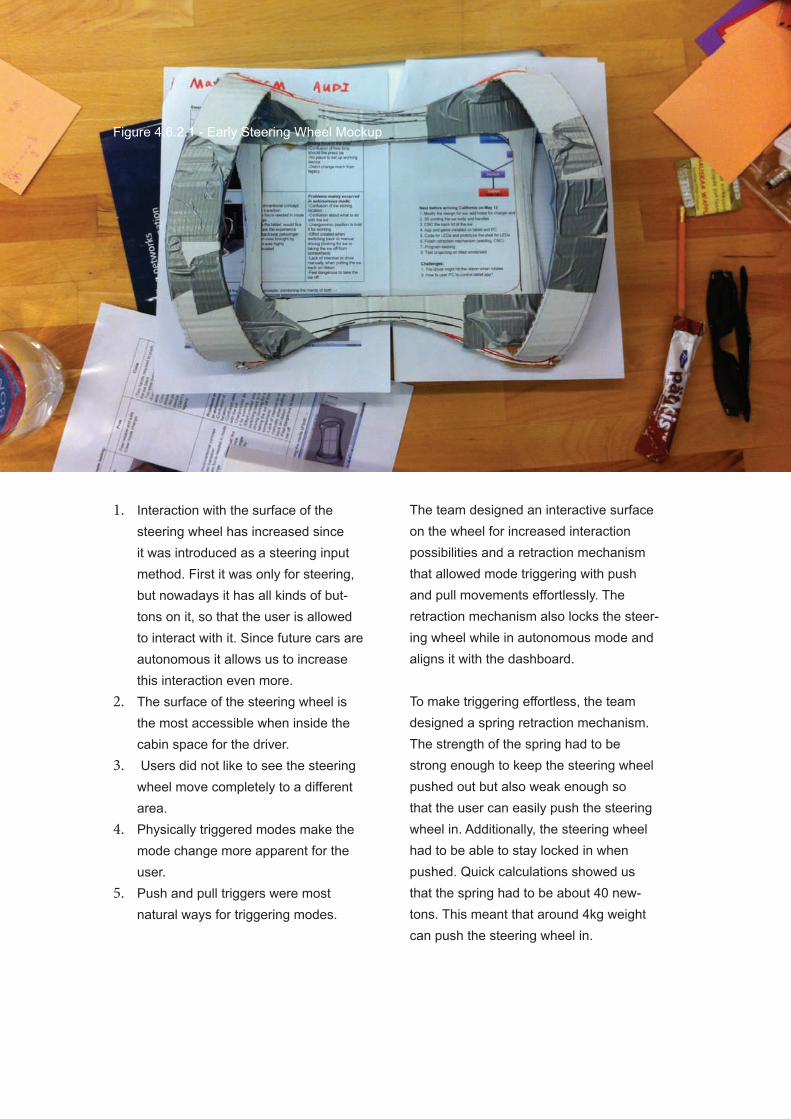
Final Documentation62
1. Interaction with the surface of the steering wheel has increased since it was introduced as a steering input method. First it was only for steering, but nowadays it has all kinds of but-tons on it, so that the user is allowed to interact with it. Since future cars are autonomous it allows us to increase this interaction even more.
2. The surface of the steering wheel is the most accessible when inside the cabin space for the driver.
3. Users did not like to see the steering wheel move completely to a different area.
4. Physically triggered modes make the mode change more apparent for the user.
5. Push and pull triggers were most natural ways for triggering modes.
The team designed an interactive surface on the wheel for increased interaction possibilities and a retraction mechanism that allowed mode triggering with push and pull movements effortlessly. The retraction mechanism also locks the steer-ing wheel while in autonomous mode and aligns it with the dashboard. To make triggering effortless, the team designed a spring retraction mechanism. The strength of the spring had to be strong enough to keep the steering wheel pushed out but also weak enough so that the user can easily push the steering wheel in. Additionally, the steering wheel had to be able to stay locked in when pushed. Quick calculations showed us that the spring had to be about 40 new-tons. This meant that around 4kg weight can push the steering wheel in.
Figure 4.6.2.1 - Early Steering Wheel Mockup

Final Documentation 63
4.6.3 Open and Clear Cabin SpaceIt is important that the cabin space lay-out was open and clear. In this design, there is only one car seat in the front, arranged in the middle of the car. The old fashioned dashboard was also removed since the team discovered electric cars will dominate the car market, therefore there would be no need for large engine compartments. Steer by wire will be the main technology for future steering wheel connections allowing the windshield to be more prominent so passengers have a better view of the driving scene. With these changes, the team dramatically increased the openness and clearness within the cabin space.
In order to better understand what the cabin space should look like, the team
conducted research about the future user, their needs, and explored the possibilities that future cars would bring. If the car is autonomous, the driver does not have to watch the road all the time. This change radically transforms socialization inside of the vehicle. As the team’s focus is on the transition between multiple activities, the driver requires increased mobility inside of the cabin. The front passenger seat was eliminated and the driver seat was positioned in the middle to drastically increase mobility and flexibility within the cabin space. This allowed the front seat to be able to rotate 360 degrees, making socialization between passengers more natural and comfortable.
Though the team focused on the transition between activities, it was still important to understand what positions would be
Table 4.6.2.2 Retraction Mechanism Explosion
Final Documentation64
needed for the most common activities that the team identified in a car, which included: driving, working, socializing, and relaxing.
DrivingThe team spent the beginning of the year researching different driving methods. After user testing multiple prototypes and many interviews, it was clear that the steering wheel is still the best way to steer the car.
Working / EntertainmentThere are multiple prototypes and emerg-ing technologies which have the potential to radically change the way people inter-act with machines and work. Considering current trends, work in the future will be digital and people will become even more digitally connected. At the same time, the future of working is strongly related to the future of entertainment, because it is both done on the same platform. The team be-gan by giving the most general solution for working by providing the user a dashboard which will also be an interactive working area. The main display of information will be a windshield with augmented reality.
SocializingThe introduction of autonomous features in cars brings socialization in the vehicles to a whole new level. Socialization inside of a vehicle will be done through technolo-gy for remote business meetings, but hav-ing a “face to face” in person conversation is something the team wanted to achieve
inside of a car as well. In order to do so, it was necessary to have a front seat rotate at least 180 degrees.
RelaxingRelaxing will be done with the seat and position adjustments. When the car is in autonomous mode, the driver has to feel comfortable and be able to freely move around.
The final cabin space design utilizes all of the advantages that an autonomous car offers. The team wanted to create some-thing that will give the a feeling of being in the car and communicate the team vision in the best possible way.
The designed cabin is open and clear. There is no big dashboard in front of the user. There is only a free flowing form (in the text we will address this free form as a a “ribbon”) that flows inside and outside of the car, creating a loop below the steer-ing wheel to make a stand for the wheel. The ribbon flows around the back seat as well, providing users a necessary feeling of a compact cabin like space for EXPE. The whole front part of the car is a large windshield that spreads all the way from the floor of the car, providing a completely new driving experience that was not possi-ble before autonomous and electrical cars. For the purpose of EXPE presentation, it was decided to imitate the windshield display with a screen on which the display and driving scenario was projected.

Final Documentation 65
Table 4.6.3.1 Cabin Space mock up

Final Documentation66

Final Documentation 67
5. Design Specifications

Final Documentation68
In this section we explain our final proto-type with more details. The section also includes the process of making the pro-totype functional. The subsystems of our final prototype are:
1. Anticipatory Chair2. Interactive Steering Wheel
5.1 Anticipatory ChairThe chair is comprised of several compo-nents: the chair electronics, the firmware development, and the rotation mecha-nism.
5.1.1 Chair ElectronicsThe chair that was used in the final design was from a 2007 Audi A8L. All of the seat
Power Supply (5V, 12V)
Car Ba6ery (12V)
Microcontroller
Chair Motor Drivers
RotaAon Motor Driver
RotaAon OpAcal Encoder
Chair Motor Sensing
Force Sensor Board
RotaAon Motor
Chair Motors
Force Sensors on Chair
functionalities and cable wiring pin outs were almost exactly the same as discov-ered from the functional prototype. The team took the basic knowledge that was gained from the functional prototype and applied it in the same exact way for the final design, thinking that the chairs would be very similar. The team discovered that all the pinouts for the motor and encoder lines were the same so the wires were isolated from the rest of the cable harness and connectors were placed in line to al-low easy connection/disconnection from the main harness.Figure 5.1.1.1 displays the system level view of the electronics portion for the design and Figure 5.1.1.2 displays the physical layout of the hardware.
Figure 5.1.1.1 System level view

Final Documentation 69
5.1.1.1 Microcontroller BoardThe heart and sole of the electronic hardware design was the microcontroller board. The functional prototype used an Arduino Atmega2560 board to control all the motors and sensor inputs. For the final design, the team decided to move away from the Arduino IDE and use the actual Atmel Studios IDE to have more control and flexibility over the microcontroller. The Arduino wrapper libraries are very handy, but for this final design, the team wanted more control over the software and wanted to eliminate all of the behind the scene actions that the wrapper library performs. The team used the reference designs of the Arduino atmega2560 as a basis to develop their own microcontroller board that was suitable for their applica-tion. One of the major differences from
the reference design to the actual design was that the team eliminated the use of a second microcontroller to use as a serial programmer for the atmega2560. Pro-gramming was performed via ISP, in-sys-tem programming, which is standard for all Atmel microcontrollers. The main benefit of designing a custom circuit board is that the connectors and female socket head-ers to all pins from the microcontroller are implemented for faster software debug-ging and modularity since all features and functionalities of the system were un-known at the time of designing the boards. Figure 5.1.1.1.1 displays the physical circuit board for the microcontroller. The schematics can be found in Appendix.
Figure 5.1.1.2 Physical layout of the hardware.

Final Documentation70
The microcontroller has three ways of re-ceiving 5V power: a DC barrel jack, a USB cable, or a power supply. There is a circuit designed to select between the power sources with the power supply having top priority if all of the sources are con-nected. The board also houses an FTDI RL232 USB to UART component used for debugging purposes and serial com-munication to the laptop that is controlling the interactive display modes of manual or autonomous mode on the steering wheel. As mentioned above, the board has female header sockets to every pin on the microcontroller to allow for quick software development, but has Molex Microclasp connectors used for modular connec-
tions for all power/signal lines to all other boards and to the chair.
5.1.1.2 Chair Motor Driver BoardThe motor driver board for the chair’s mo-tors is exactly the same as designed for the functional prototype. H-Bridge circuits were created out of DPDT switches to allow for the motors’ bi-directional abilities. Shottky diodes were placed in reversed biased across the coils and the motors to help reduce the inductive kickback when the motor was shut down. One major dif-ference from the functional prototype to this final design is that the SPDT switches used to connect +12VDC or GND to the supply power to the motor were replaced
Figure 5.1.1.1.1 - Physical circuit board for the microcontroller

Final Documentation 71
a better experience in the chair. Figure 5.1.1.2.1 displays the revised schemat-ics with the power transistor as the power enable component and Figure 5.1.1.2.2 shows the physical circuit board that was created.
with a power transistor. The team noticed from user testing that the stop and start motion of the chair movements were very noticeable and not smooth. The team decided that having a smooth ramping function through pulse width modulation (PWM) was necessary to give the user
Figure 5.1.1.2.1 - Schematics
Figure 5.1.1.2.2 - Physical circuit board
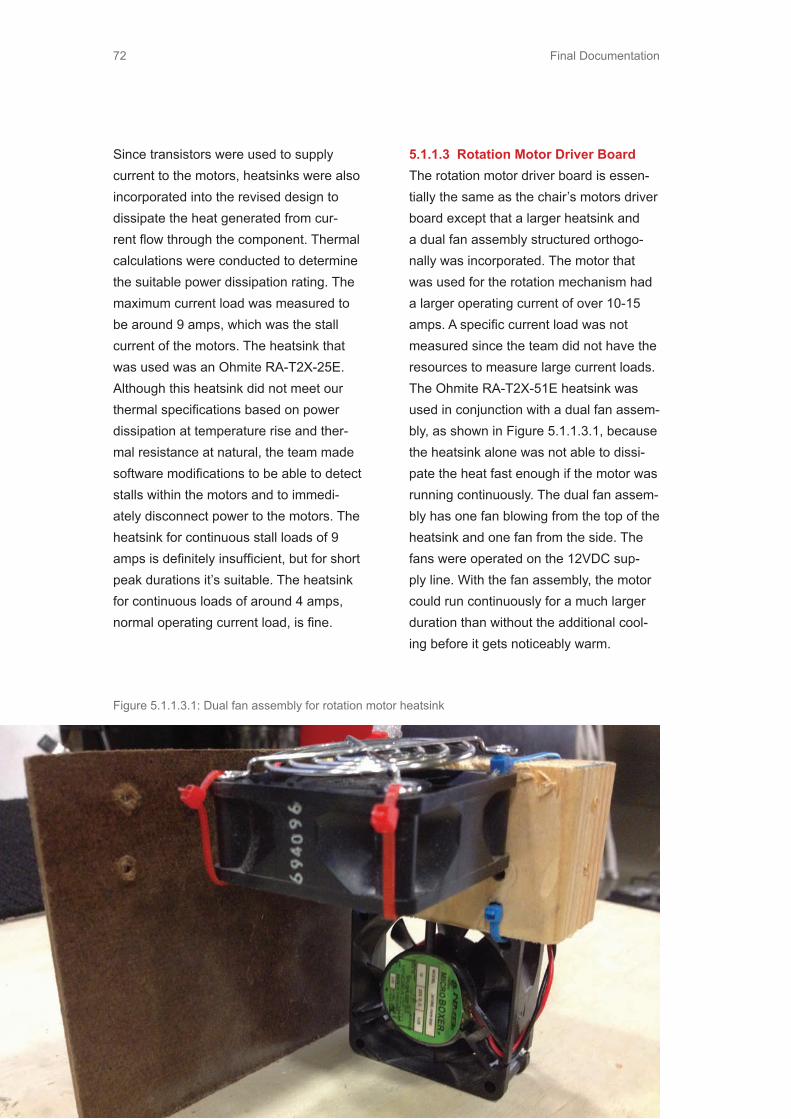
Final Documentation72
Since transistors were used to supply current to the motors, heatsinks were also incorporated into the revised design to dissipate the heat generated from cur-rent flow through the component. Thermal calculations were conducted to determine the suitable power dissipation rating. The maximum current load was measured to be around 9 amps, which was the stall current of the motors. The heatsink that was used was an Ohmite RA-T2X-25E. Although this heatsink did not meet our thermal specifications based on power dissipation at temperature rise and ther-mal resistance at natural, the team made software modifications to be able to detect stalls within the motors and to immedi-ately disconnect power to the motors. The heatsink for continuous stall loads of 9 amps is definitely insufficient, but for short peak durations it’s suitable. The heatsink for continuous loads of around 4 amps, normal operating current load, is fine.
5.1.1.3 Rotation Motor Driver BoardThe rotation motor driver board is essen-tially the same as the chair’s motors driver board except that a larger heatsink and a dual fan assembly structured orthogo-nally was incorporated. The motor that was used for the rotation mechanism had a larger operating current of over 10-15 amps. A specific current load was not measured since the team did not have the resources to measure large current loads. The Ohmite RA-T2X-51E heatsink was used in conjunction with a dual fan assem-bly, as shown in Figure 5.1.1.3.1, because the heatsink alone was not able to dissi-pate the heat fast enough if the motor was running continuously. The dual fan assem-bly has one fan blowing from the top of the heatsink and one fan from the side. The fans were operated on the 12VDC sup-ply line. With the fan assembly, the motor could run continuously for a much larger duration than without the additional cool-ing before it gets noticeably warm.
Figure 5.1.1.3.1: Dual fan assembly for rotation motor heatsink

Final Documentation 73
Figure 5.1.1.4.1: Motor position sensing circuit schematic
FIgure 5.1.1.4.2 Motor position sensing board
5.1.1.4 Chair Motor Sensing BoardThe motor sensing board for the chair’s motors is the same schematic design as constructed for the functional prototype. A comparator was used to level-shift the encoder output square-wave to a 0-5V
range that would be compatible for most microcontrollers. Figure 5.1.1.4.1 displays the schematic circuit design and Figure 5.1.1.4.2 displays the physical circuit board that was created.

Final Documentation74
5.1.1.5 Rotation Optical EncoderAn optical encoder was used to determine the position of the rotation mechanism. A one inch 360 degree circle with black and white stripes were used to obtain a square wave pulse from 0-5V from every color transition. The circle of stripes alternated colors with every degree and was as wide a encoder tape sensor. This type of optical encoder was more effective than attach-ing one to the shaft of the motor because the position had to be known relative to the turntable that the chair was on and not the motor. If the encoder was connected to the shaft, there were factors that made the source unreliable since the motor shaft was connected to a gearbox and then a vertical shaft. The encoded circle was placed underneath the turntable.
Figure 5.1.1.5.1 Rotation encoder - optical
sensor and circle of stripes
5.1.1.6 Force Sensing ResistorsDuring the functional prototype, square FSR sensors were used and placed in areas that would be beneficial to obtain weight distribution data. Data collected from the prototype seemed reasonable but only for certain body types and for only common cases. The team wanted to de-sign a system that would be able to detect and accommodate various body types us-ers had, and change the thresholds based on that body type. For example, tall/wide users would have a high threshold level to meet since it is reasonable to assume that more of their body weight would be press-ing the sensors. One major finding from the functional prototype was that the small square FRSs were insufficient in gather-ing data from different body types so a different kind of FRS was used. Figure 5.1.1.6.1 displays the initial configuration of FSRs that were tested with for the final design.
Figure 5.1.1.6.1: Initial configuration of FSR
tested

Final Documentation 75
Long, thin FSRs by Interlink (408 series) were used in conjunction with the square FSRs to help with accommodating various body types. The 408 series only measure the total amount of force on the sensor and not the location where the pressure is applied. The longer sensors for the sides and the shoulders are beneficial for height detection since it had a much larger area to sense shorter and tall people within a fixed position. Initially, all the sensors shown in Figure 5.1.1.6.1 were used to differentiate the tilting and rotating functions but after threshold testing with various users, it was evident that more sensors were not necessarily the best solution for distin-guishing different intentions. Having less sensors was better since it helped reduce the amount of misfires from uncontrol-lable factors. The sensors on the bottom cushion were not used in the final design due to many factors that could not be solved by simple software algorithms. One observation during the threshold testing was that users would often have objects in their pockets, which caused the readings from the sensors to not accurately reflect the user’s body. Another key observation was that users do not sit symmetrically on the chair nor do they sit within a consist-ent pattern. Most users tend to sit more toward the right side with more pressure applied on the right side. This could have been compensated for within software but another uncontrollable factor that caused problems with the sensor readings was that the 408 series FSRs were placed
directly on the chair back side cushions. Since these cushions compress and expand naturally, it was hard to get an accurate reading since slight user adjust-ments would cause unpredictable devia-tions from a calibrated zero reading. For the final design, only the chair seat back side sensors and the two middle square sensors were used for rotation and tilting back respectively. The circuit design was exactly the same as from the functional prototype. The same board was actually used but with slight modifications. Two extra sensor slots were added to accommodate the sensors for the sliding function via the footpad. Figure 5.1.1.6.2 displays the FSR protoboard and Figure 5.1.1.6.3 displays the circuit schematics.
Figure 5.1.1.6.2 FSR protoboard

Final Documentation76
OUTIN7IN6IN5IN4IN3IN2IN1IN0ABVSS
VDDIN8IN9
IN10IN11IN12IN13IN14IN15
INHIBITCD
T3T4T5T6
GNDCONTROL_CCONTROL_D
T2T1B6B5B4B3B2B1
CONTROL_ACONTROL_B
TI - CD4067BE
CD4067BE
GND
OUT+5VDC
Figure 5.1.1.6.3: FSR circuit schematic
5.1.1.7 Override SwitchesFrom the functional prototype, the team observed that users felt more comfortable having some kind of override switch so that if the chair does something that the user didn’t want it to do, the user could use the switches to stop it and correct it.
The original adjustment switches located on the side of the chair were the most reasonable to use as an override point. Just like from the functional prototype, the resistance from each throw from the momentary SPDT was measured as 391
Figure 5.1.1.7.1: Switch override circuit schematic and protoboard

Final Documentation 77
ohms and 822 ohms. A resistance of 470 ohms in series with the 5VDC power line to the actual switch enabled the voltage level for the 391 ohm side as 2.36V (ADC 10 bit value of 466) and a voltage level of 3.30V for the 822 ohm side (ADC 10
Figure 5.1.1.7.2: Switch override protoboard
Figure 5.1.1.8.1: Master control box
bit value of 652). The protoboard that was made connects directly to the origi-nal switch adjustment connector. Figure 5.1.1.7.1 displays the circuit schematic for one of the switch and Figure 5.1.1.7.2 displays the protoboard that was made.
5.1.1.8 Master Control BoxA master control box was designed mainly for the convenience of having users try out the system at EXPE. The control box has several main functions: allows the system to be reset (software) without having to touch the reset button on the microcon-troller board, to calibrate the FSR thresh-olds depending on user’s body type, to reset the chair to the default position, and to enable/disable the code functions. The software reset switch is directly connected to the reset pin on the microcontroller. The chair reset and the FSR calibration
switch are connected directly as input I/O pins. The enable/disable system switch is connected to an external interrupt pin that determines whether the switch is in a high or low state. The control box also features an LCD screen so that one can determine
exactly what state the system is in for debugging and normal operation modes. Figure 5.1.1.8.1 displays the master con-trol box.

Final Documentation78
5.1.2 Firmware DevelopmentThe basic firmware process flow can be seen in Figure 5.1.2.1. The code can be seen in Appendix XX.
System Enable
?
Auto Mode ?
Drive Mode ?
FSR
Calibrate ?
Reset Chair ?
Read FSR
SLIDE, TILT, OR
ROTATE
Determine thresholds Based on body type
Reset chair to default pos
Move into drive pos
Switch Override Disabled
?
Y
N
Check override SW touched
SW touched
?
Move chair motors
accordingly
N
Y
N
Y
Y
N
Y
N N N
Y Y
Figure 5.1.2.1: Firmware process flow

Final Documentation 79
The code first determines whether the FSR calibration switch or the reset chair switch from the master control box has been turned on. If the FSR calibration switch has been turned on, the FSR sen-sor values are collected through the ADC and the user’s body type is determined based on a certain threshold level. The body type is categorized as short, me-dium, tall for the height and thin, aver-age, and wide for the width. The height category is used to determine the tilt back thresholds while the width category is used to determine the rotation thresholds. If the reset chair position switch is turned on, then the chair moves each of the motors to its zero position regardless of current encoder position. Once the motors stall, then the chair resets to a default position setting. The code is separated into several categories that include switch override, system enable, auto mode, and drive mode. The switch override system is necessary to enable the user to be able to stop the chair’s movement if it does something that the user doesn’t want it to do. If the switch override is enabled, then the software checks whether any of the switch adjustments on the chair side has been active/touched. If no switches were touched, the code cycles back through the main loop, but if they were touched, then it determines which switch was activated and moves the corresponding motor as long as the switch is active. One switch is checked every 40 ms via a timer and
cycles through each switch. If the switch override is disabled and system functions are active, then the retractable steering wheel position dic-tates whether the user is in autonomous or drive mode. If the steering wheel is in drive mode, the chair will proceed into a drive position setting only with all other functions deactivated. If the steer-ing wheel is in autonomous mode, the chair reads the FSR sensors and checks against three different functions: a tilt back, a slide, and a rotate function.
5.1.2.1 Tilt FunctionThe tilt function is activated once the user holds the two centered back FSRs above a certain pressure value for a certain amount of time. This helps eliminates a lot of misfires due to small adjustments made by the user. If the chair back moves backwards, the user must lean forward slightly to make the FSR values go below a certain threshold level to stop the chair. The same actions also correspond when the chair moves forward and the user wants to stop the chair. While the tilt func-tion is enabled, no other function can be activated.
5.1.2.2 Slide Forward/Back FunctionThe slide forward/back function is acti-vated when the user pushes or pulls the footpads just like the tilt function. To move backward, the user must push forward twice while holding the second push. This slight impulse nudge is necessary to help

Final Documentation80
distinguish between sliding and tilting. Us-ers tend to push with their feet when tilting backward, and would cause a misfire on the sliding function. Having this slight impulse before holding the second push helps distinguish the user intentions with-out much effort. The code determines if the slight nudge is conducted and if there are X amount of samples above a certain threshold. If so, then it goes into a waiting period. If the second push is conducted between the waiting period then the user will slide back, if not, then the user will have to conduct the nudge again. While the slide function is enabled, no other function can be activated.
5.1.2.3 Rotate FunctionThe rotate function is activated when the user shifts their body to either the left or the right side. When the user is facing toward the front, the user is restricted to turn to the right up to 180 degree. When in rotation mode, the tilting and sliding func-tions are disabled because of the restric-tions with the steering wheel clearance. If the user initiates rotation mode but the chair is outside of the steering wheel clearance boundary, the chair moves to a set clearance position prior to rotating. Once the user is rotated, the user would relieve some of the pressure from the activating side to stop or rotate all the way up to 180 degrees. To exit out of rotation mode, the user must rotate towards the front all the way to 0 degrees for the tilt and slide back function to be re-enabled.
5.1.2.4 Move Motor FunctionThe code was structured to be able to take advantage of a PID motor controller function. Although PWM gave the team speed control over the chair’s motor, having a way to determine at what rate the speed should be controlled was an issue. A PID controller helps take into ac-count how fast the microcontroller should increase or decrease motor speed until it reaches it’s targeted set position. The move motor function first determines the delta position from its set and current position. Once the error is calculated, the result of the PID equation can be cal-culated and the PWM value will change according to how far away the current position is from the set position. Once the motor reaches its targeted value, the mo-tor would be disabled and the move motor
Figure 5.1.3.2.1: Chair Dimensions
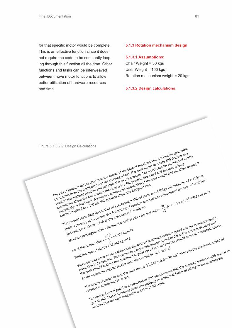
Final Documentation 81
for that specific motor would be complete. This is an effective function since it does not require the code to be constantly loop-ing through this function all the time. Other functions and tasks can be interweaved between move motor functions to allow better utilization of hardware resources and time.
5.1.3 Rotation mechanism design
5.1.3.1 Assumptions:Chair Weight = 30 kgsUser Weight = 100 kgsRotation mechanism weight = 20 kgs
5.1.3.2 Design calculations
The axis of ro
tatio
n for the ch
air is a
t the ce
nter of the base of th
e chair. This is based on geometric
constraints from th
e dashboard and the steerin
g wheel. The ch
air n
eeds to
rotate 180 degrees in a
comfortable re
clined position and still clear the steerin
g wheel. The worst ca
se for m
oment o
f inertia
calcu
latio
ns about th
e axis is when the chair is in a flat p
osition like a bed and th
e user is lying
completely reclined on it. Assum
ing a continuous distrib
ution of th
e user weight and th
e chair w
eight, it
can be im
agined as a
130 kgs slab ro
tatin
g about the designed axis.
The lumped mass d
iagram
consists o
f a re
ctangular slab of mass
130m
kgs=
(dimensio
ns –
155l
cms=
and
56bcms
=) and a circular disc (consistin
g of ro
tatio
n mechanism
components) of m
ass
' 30m
kgs=
and radius
35rcms
=. Shift of th
e main axis is
' 40l
cms=
MI of the re
ctangular slab = MI about a ce
ntral axis +
parallel shift =
22
2
() ( ')
12m b l
m l+
+=50.22 kg-m^2
MI of the circular disc =
2'2
m l=1.225 kg-m^2
Total m
oment o
f inertia = 51.445 kg-m
^2
Based on te
sts d
one on th
e sw
ivel ch
air the desire
d maximum
rotatio
n speed was se
t as o
ne co
mplete
revolutio
n in 11 seconds. That co
mes to
a maximum
angular sp
eed of 0.6 rad/sec. It was decided th
at
the chair should achieve this maximum
angular sp
eed in 1 se
c and th
e should move at a co
nstant sp
eed.
So th
e maximum
angular acceleration then would be
2
0.6 / srad
The torque re
quire
d to tu
rn th
e chair then is
51.445 x 0.6 = 30.867 N-m and the maximum
speed of
rotatio
n is approximately 6 rpm.
The selected worm gear h
as a re
duction of 40:1 which means th
at th
e require
d torque is 0.75 N-m at an
rpm of 240. That is o
peratin
g point and applying an additional factor of safety on th
ose values we
decid
ed th
at th
e operating point is 1
N-m
at 300 rp
m.
Figure 5.1.3.2.1: Chair Dimensions
Figure 5.1.3.2.2: Design Calculations

Final Documentation82
5.1.3.3 Initial rotation prototypeThe first prototype of the rotation mecha-nism was designed using a 40:1 reduction worm and a worm gear from McMaster Carr. The connecting components were machined.
A motor was selected from AmpFlow. This motor operates on 24V and has a stall torque of 5 N-m and a no load rpm of 5600 at 24V. These specifications far exceed the calculated ones including a factor of safety. The team planned to run
Figure 5.1.3.3.2 - Rotation first prototype 2
Figure5.1.3.3.1 - Rotation first prototype 1

Final Documentation 83
this motor at 12V. This made it easier to use transistors for PWM switching of the motor.There was a lot of noise and alignment issues with this mechanism. This also caused a lot of vibration which could be felt by the users as it was being transmit-ted through the platform and onto the chair that was connected to it.
5.1.3.4 Final Rotation MechanismIt was decided to go for an industrial worm gearbox in order to remove the noise, vibrations and resolve all alignment issues related to the gearbox. Flexible couplings were used at the input and output shafts of the gearbox to connect the motor to the gearbox and to connect the gearbox to the platform. Figure 5.1.3.4.1 shows the first assembly of the gearbox.
Figure 5.1.3.4.1 - Rotation mechanism initial assembly
Figure 5.1.3.5.3 - Rotation connection to motor
Figure 5.1.3.4.2 - Rotation connection to platform
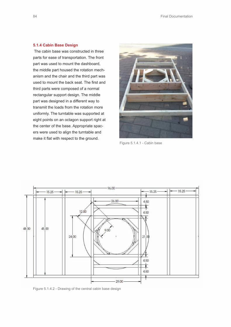
Final Documentation84
5.1.4 Cabin Base Design The cabin base was constructed in three parts for ease of transportation. The front part was used to mount the dashboard, the middle part housed the rotation mech-anism and the chair and the third part was used to mount the back seat. The first and third parts were composed of a normal rectangular support design. The middle part was designed in a different way to transmit the loads from the rotation more uniformly. The turntable was supported at eight points on an octagon support right at the center of the base. Appropriate spac-ers were used to align the turntable and make it flat with respect to the ground.
Figure 5.1.4.1 - Cabin base
Figure 5.1.4.2 - Drawing of the central cabin base design

Final Documentation 85
5.1.5 Footpad DesignThe footpad was constructed in three lay-ers (each a 0.25 inch in thickness) - the base layer, the middle layer that serves as a support and an upper section consisting of the actual actuation element/section and the housing around it. The footpad is 22” long and 19” wide. The three layers have been shown in the following figures - 5.1.5.1; 5.1.5.2; 5.1.5.3
The middle layer has a slot in it to route the wires of the two force sensors that have been placed at the front and back of the footpad.
Figure 5.1.5.4 - Footpad top view showing wire routing
Figure 5.1.5.1 - top footpad layer
Figure 5.1.5.2 - bottom footpad layer Figure 5.1.5.3 - middle footpad layer
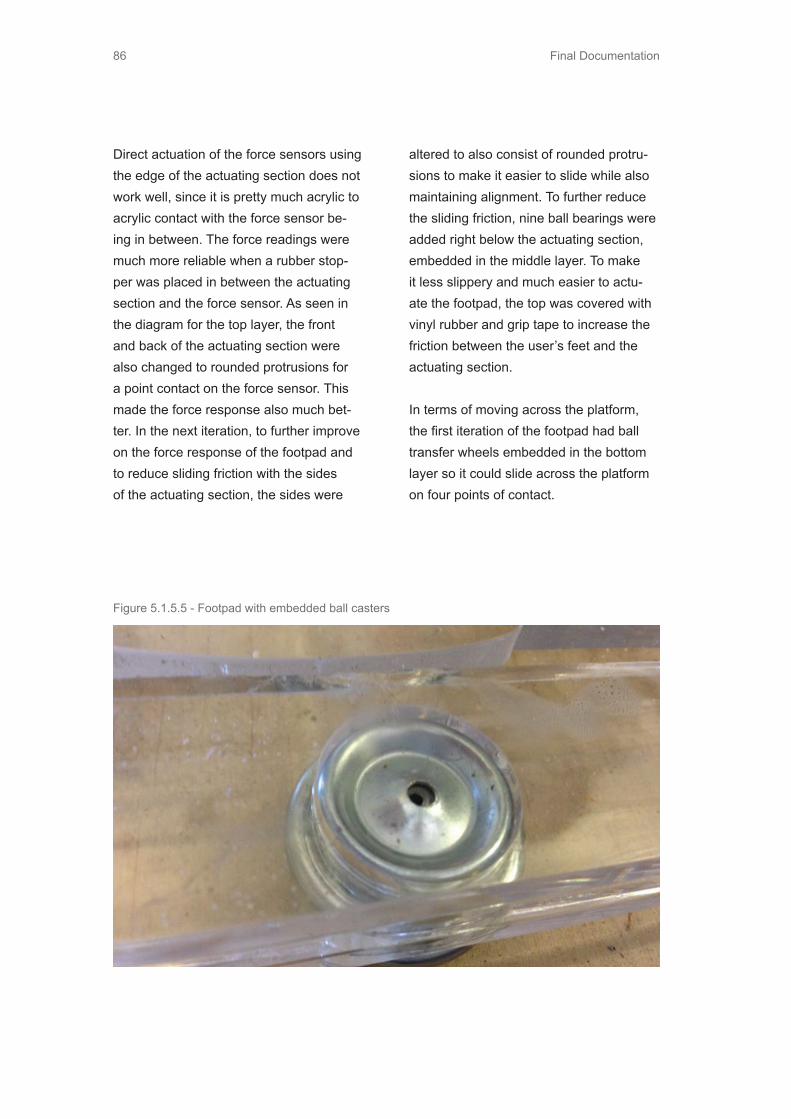
Final Documentation86
Direct actuation of the force sensors using the edge of the actuating section does not work well, since it is pretty much acrylic to acrylic contact with the force sensor be-ing in between. The force readings were much more reliable when a rubber stop-per was placed in between the actuating section and the force sensor. As seen in the diagram for the top layer, the front and back of the actuating section were also changed to rounded protrusions for a point contact on the force sensor. This made the force response also much bet-ter. In the next iteration, to further improve on the force response of the footpad and to reduce sliding friction with the sides of the actuating section, the sides were
altered to also consist of rounded protru-sions to make it easier to slide while also maintaining alignment. To further reduce the sliding friction, nine ball bearings were added right below the actuating section, embedded in the middle layer. To make it less slippery and much easier to actu-ate the footpad, the top was covered with vinyl rubber and grip tape to increase the friction between the user’s feet and the actuating section.
In terms of moving across the platform, the first iteration of the footpad had ball transfer wheels embedded in the bottom layer so it could slide across the platform on four points of contact.
Figure 5.1.5.5 - Footpad with embedded ball casters

Final Documentation 87
When the carpet was added this sliding led to a lot of friction, thereby increas-ing the torque required by the rotation mechanism to turn the chair. The final iteration of the footpad does not consist of the caster wheels and is supported by a structure connected to the turning platform that is rigid enough to not let the footpad touch the ground when the user’s feet are resting on it. This makes the footpad essentially float above the platform while rotating, which leads to a much better torque efficiency.
5.2 The Interactive Steering WheelThis subsystem is a combination of the retraction mechanism and the steering wheel. The retraction mechanism is a con-struction that allows the user to do physi-
cal push and pull triggers for mode trigger-ing. The steering wheel is a new design for a sleeker aesthetic and is mounted to this retraction mechanism.
Steering Wheel Parts for this Interactive Steering Wheel were created with a 3D printer (Picture bellow), except for the bottom part which was manufactured with a CNC mill. The interactive screen was made using a used Android tablet.
Retraction MechanismParts in this mechanism are hand made using various manufacturing processes including lathe, welding, sheet metal cut-ting and bending.
Figure 5.2.1 - 3d Printing of Steering Wheel

Final Documentation88
5.2.1 Structure of The Interative Steering Wheel
Retraction Mechanism
Interactive Steering Wheel
Android Tablet
HandlesFrame
Figure 5.2.1.1 - Steering Wheel
Figure 5.2.1.2 - Steering Wheel Parts

Final Documentation 89
Back Lid
Tightening Band
Outter shaftFlange
Ejection Spring
Switch
Microswitch Support
Lid
Inner Shaft
Base
Figure 5.2.1.3 - Steering Wheel Parts Back
Figure 5.2.1.4 - Retraction Mechanism Parts

Final Documentation90
5.2.2 The Making of The Interactive Steering WheelThe CAD model was created in Rhinocer-ous modeling software and divided into two categories: • Milled parts• 3D-printed parts
Milled PartsThe Back Lid was manufactured by CNC milling machine out of blue prototype plastic.
3D-Printed PartsThe maximum size of Aalto Digital Design Laboratory’s uPrint printing envelope was 150x210 mm, so also the model had to be splitted into several pieces, which together formed the Frame and Grip parts. The model was generated into 14 parts that were connected with studs that fit perfectly to the corresponding holes. The settings of the prints was to print solid ABS and altogether 561,39 cm^3 build material and 197,43 cm^3 support material was used within 44,47 hours of printing. After printing the parts, they were washed in an ultrasound bath in order to dissolve the support material from the actual ABS.
TabletThe tablet was selected by the size, the operating system and the price. Gal-axy Tab 2 was one of the most obvious selections since it has 10.1’’ large screen, android as a operating system and is one of the cheapest in its price category. The android is well known for its capabili-
ties with a modification friendly operating system based in linux. The tablet was rooted, which means installing over the manufacturer’s firmware with a custom ROM in order to free up more functionali-ties that were not allowed with the manu-facturer’s settings and also sets free the superuser(SU) functionality in order to receive commands over WiFi. In this case, the team used a ROM called Cyanogen-mod 9.1.0 since it was easily accessible and the instructions were available.
FinishingAfter printing the parts, they were glued together and finished. The parts were filled and sanded before they were painted. After filling, sanding and painting, the tablet was inserted into the back lid and screwed on the frame.
Retraction MechanismBaseThis part of structure was CNC milled from blue prototype plastic and aluminum. The Base is made out of plastic and the Tightening Bands are made out of alu-minum. The 3D models were made with Creo CAD software and those models were analyzed with Mastercam which made the milling paths numerically for the CNC milling machine. After milling, two M10 pressing screws were put on both tightening bands. The tightening bands are attached to the base with M5 bolts. Figure n shows the manufactured parts and the dimensional drawings can be seen bellow.
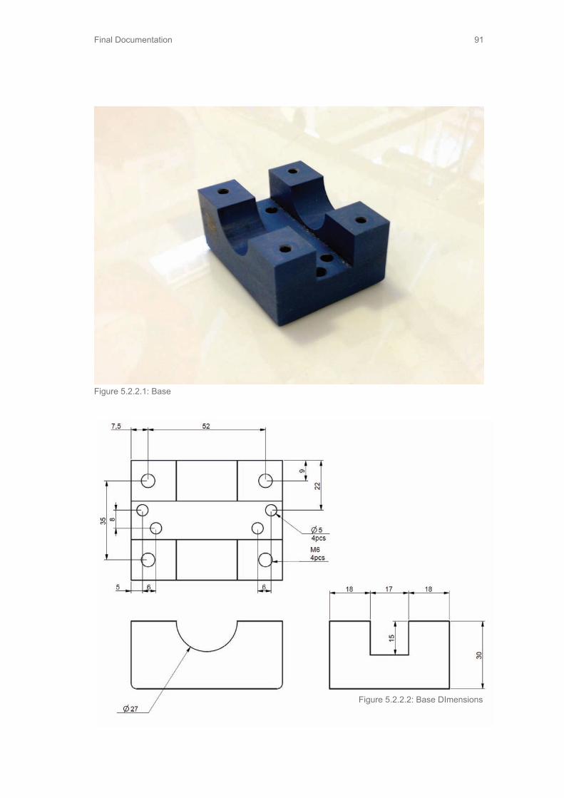
Final Documentation 91
Figure 5.2.2.1: Base
Figure 5.2.2.2: Base DImensions

Final Documentation92
Figure 5.2.2.3: Tightening Bands
Figure 5.2.2.4: Tightening Bands Dimensions
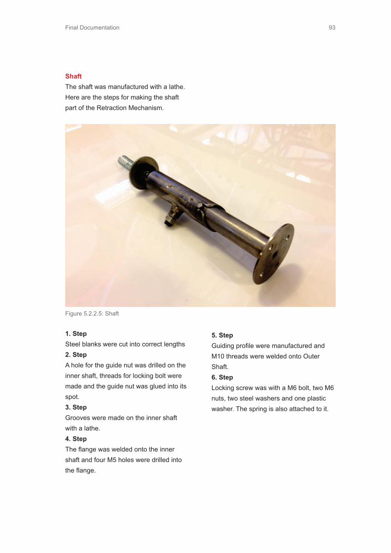
Final Documentation 93
ShaftThe shaft was manufactured with a lathe. Here are the steps for making the shaft part of the Retraction Mechanism.
1. StepSteel blanks were cut into correct lengths2. StepA hole for the guide nut was drilled on the inner shaft, threads for locking bolt were made and the guide nut was glued into its spot.3. StepGrooves were made on the inner shaft with a lathe.4. StepThe flange was welded onto the inner shaft and four M5 holes were drilled into the flange.
5. StepGuiding profile were manufactured and M10 threads were welded onto Outer Shaft.6. StepLocking screw was with a M6 bolt, two M6 nuts, two steel washers and one plastic washer. The spring is also attached to it.
Figure 5.2.2.5: Shaft
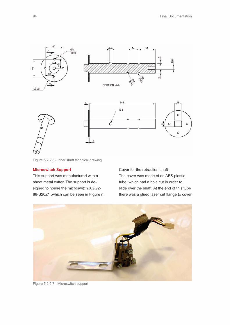
Final Documentation94
Figure 5.2.2.6 - Inner shaft technical drawing
Figure 5.2.2.7 - Microswitch support
Microswitch SupportThis support was manufactured with a sheet metal cutter. The support is de-signed to house the microswitch XGG2-88-S20Z1 ,which can be seen in Figure n.
Cover for the retraction shaftThe cover was made of an ABS plastic tube, which had a hole cut in order to slide over the shaft. At the end of this tube there was a glued laser cut flange to cover

Final Documentation 95
where the retraction mechanism met the dashboard. On top of this ABS plastic covering there was leather covering velcro onto it.
Assembled Retraction MechanismAfter all the parts are manufactured the retraction mechanism was assembled as seen in Figure 5.2.2.8
5.2.3 The interaction specifications of the steering wheelGeneral overview of the setup and func-tionalitiesThe interaction part of the steering wheel was meant to fulfill a simple purpose: to demonstrate that the windshield can be utilized as display while the car is driven in autonomous mode. In order to change these modes the steering wheel retraction gave the signal for the tablet to change the app and indicate the mode change in words on the tablet screen. The steering wheel also provide some haptic feedback by vibrating twhen a mode change oc-curred. For the windshield, this meant that there was an additional interactive window over the driving scenario to represent our vision of the future of work. There were
pictures of different recognizable appli-cations like facebook, google calendar or a movie. These applications could be viewed by simply swiping through the op-tions on the tablet.
5.2.4. Communications between devicesProtocols used:Android Debug Bridge (ADB), wifi port 5555TUIO protocol, wifi port 3333http, wifi port 80Universal Asyncronous Receiver Transmit-ter, UART, Physical USB cable
The setup can be seen in the schematics picture below. The trigger for the mode change was a physical switch behind the steering wheel at the end of the short steering shaft. The switch sent information to the microcontroller through wires that the end of shaft when moved to the other position. The microcontroller used UART communications to send either the letter ‘M’ for manual mode or the letter ‘A’ for autonomous mode to the serial port. On the Mac side, there was a python script listening to the serial port and determining what actions to perform. The python script operated web browsers on the projec-tor through an applescript code and sent the commands via wifi to the tablet which was listening to the ADB commands. The tablet sent back TUIO protocol data for the computer in order to control the app on the windshield display by swiping. A program called Tongseng was used to lis-ten and pass the TUIO data to the caress
Figure 5.2.2.8 - Assembled Retr. Mechanism

Final Documentation96
webserver. Javascript was used to make the webpages functional and for receiving the touch events sent by Tongseng.
USB cable
Microcontroller
Touch events TUIO protocol
Commands over ADBData to computer
Projector canvas
Caress servernode.jspython scriptTongseng
Mac computerProjector
App
Mechanical switch behind the steering wheel
VGA cable
WiFi router Galaxy Tab 2 tablet
Apps and hardware commands
Data to tablet
Figure 5.2.4.1: Communication schematics
The physical implementation of the setup can be seen in the following picture.
Figure 5.2.4.2: Physical Implementation

Final Documentation 97
Figure 5.3.1.1 - Gluing the pieces
5.3 Open and Clear Cabin Space5.3.1 The Making of Open and Clear Cabin SpaceThe dashboard:Laser cutting the Duron pieces:The team opted to make the dashboard economically. The shape of dashboard was first designed in Rhino. It was sliced into 250 pieces so that laser cut duron pieces could then be stacked to create the shape.
Material needed: 3 ft x 4ft 1/4in Duron sheets8 sheets
Gluing the pieces: Each piece was numbered for easier as-sembly. On each piece, there was also a rastered line to guide where the next piece should be glued. Material needed:Wood glueClamps

Final Documentation98
Sanding and applying fillerThe team next spent 2 weeks sanding off the edges and applying Bondo to make the surface smooth and curved. (kuva taalla) In order to prevent the wood part from cracking when force was applied, the dashboard was then covered in fiberglass.
Material needed:Sanding machineGrinder40 pieces of 60 sand paper20 pieces of 150 sand paper3 cans x wood filler5 cans x Bondo Fiberglass kit
Coloring The dashboard was finished by applying primer and flat black spray paint. (picture of dashboard)Material needed:6 x primer6 x flat black spray paint
Figure 5.3.1.2 - Sanding the dashboard
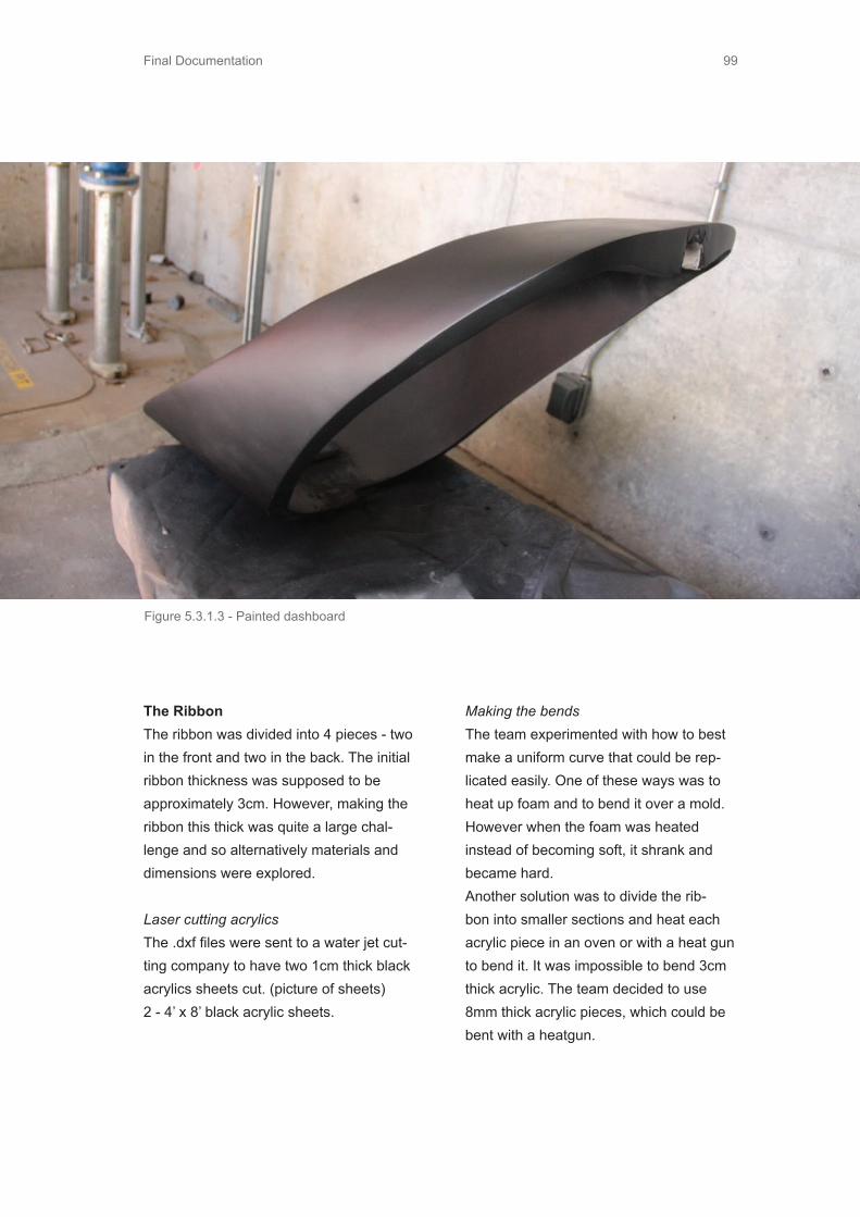
Final Documentation 99
The RibbonThe ribbon was divided into 4 pieces - two in the front and two in the back. The initial ribbon thickness was supposed to be approximately 3cm. However, making the ribbon this thick was quite a large chal-lenge and so alternatively materials and dimensions were explored.
Laser cutting acrylicsThe .dxf files were sent to a water jet cut-ting company to have two 1cm thick black acrylics sheets cut. (picture of sheets)2 - 4’ x 8’ black acrylic sheets.
Making the bendsThe team experimented with how to best make a uniform curve that could be rep-licated easily. One of these ways was to heat up foam and to bend it over a mold. However when the foam was heated instead of becoming soft, it shrank and became hard. Another solution was to divide the rib-bon into smaller sections and heat each acrylic piece in an oven or with a heat gun to bend it. It was impossible to bend 3cm thick acrylic. The team decided to use 8mm thick acrylic pieces, which could be bent with a heatgun.
Figure 5.3.1.3 - Painted dashboard

Final Documentation100
Because of the restrictions in time and the amount of work, the team chose to use thinner acrylic that could be heated and bent. Since the pieces were rather large, a grill was used to heat the entire section of the acrylic and was molded over a trash-can to proper radius.
PaintingThe ribbon was spraypainted flat black to match the dashboard.Material needed:1 piece of 600 sand paper2 x primer2 x flat black spray paint
Mounting the ribbon The ribbon is created to stand on pillars to keep it at the right height. Wooden pillars and plastic pipes were used as the sup-
ports. The wood pillars were inserted into the plastic pipes, which were mounted and screwed to the platform.A piece of 2x4 wood was attached to the bottom of the ribbon. It made gluing the wood to the plastic easier, as well as at-taching the pillars to the plastic. These pil-lars got screwed to the into each wooden board.
Figure 5.3.1.4 - Banding the ribbon
Figure 5.3.1.5 - Barbecuing the ribbon

Final Documentation 101
To attach the ribbon to the floor, the team drilled holes in the floor and then placed small plastic pipes through those holes. Below the floor, we glued those pipes to a small wooden board that we screwed to the floor from below
Wooden Pillars
2x4 Wooden Board
Ribbon
Plastic pipe
Figure 5.3.1.6 - Mounting the ribbon
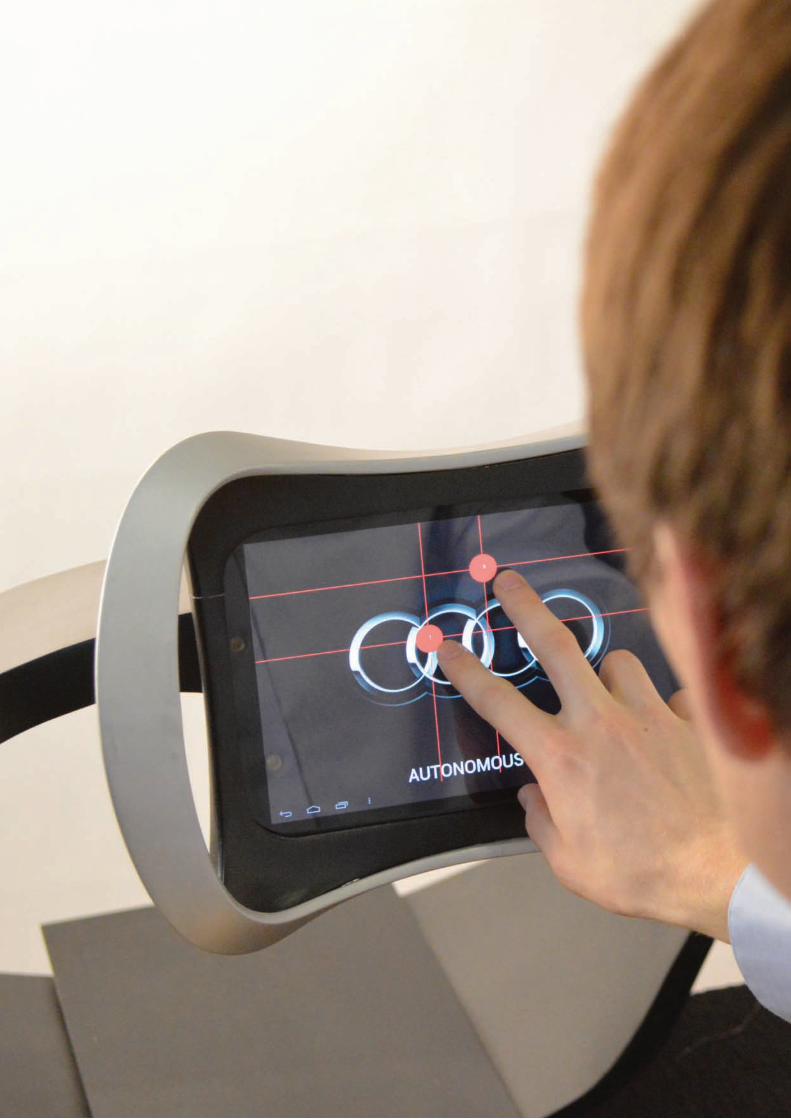
Final Documentation102

Final Documentation 103
6. Project Planning andManagement

Final Documentation104
6.1 Deliverables and MilestonesDate Deliverables
10/22/12 Corporate Project Team Formation
11/8/12 Benchmarking review
11/29/12 Critical Function Prototype
12/4/12 Fall project brochure
12/6/12 Fall presentation
12/11/12 Fall documentation due
1/23/13 First meeting with Audi contact and engineers in Ingolstadt
1/24/13 Second meeting with Audi HMI lab representative in Ingolstadt
1/18/13 - 1/29/13 Dark horse prototyping
1/31/13 - 2/14/13 Funky prototyping
2/15/13 - 2/28/13 Functional prototyping
3/3/13 First vision locked
3/10/13 Turning point brochure
3/12/13 Turning point presentation
3/13/13 - 3/16/13 Aalto in Geneva Motor Show
3/21/13 Winter documentation due
3/22/13 - 3/31/13 Stanford in Helsinki
3/27/13 First whole team meeting with Audi locking concept
4/18/13 X is finished
5/12/13 Aalto in Stanford
5/16/13 Penultimate is due
5/28/13 EXPE brochure is due
6/6/13 EXPE
6/11/13 Final documentation due
Table 6.1.1 - Deliverables and milestones

Final Documentation 105
Date Vendor Item Purpose Amount
11/1/2012 Amazon Mindflex Game Benchmarking $55.99
11/4/2012StanfordBookstore
Batteries andmarkers
Materials forBenchmarking
$30.44
11/21/2012 Sparkfun Accelerometer CFP $38.23
Date Vendor Item Purpose Amount
14/11/2012MechanicalEngineering Guild
Van renting CEP €38.95
27/11/2012 Verkkokauppa Saitek Aviator PC Steering Testing €49.90
27/11/2012 VerkkokauppaGran Turismo 5PS3
Steering Testing €24.90
27/11/12 VerkkokauppaThrustmasterExperienceRacing Wheel
Steering Testing €57.10
28/11/12ABC GasStation
Diesel gasolinefor Audi A6
Audi A6 TestDrive
€26.93
Table 6.2.2: Aalto Spendings - Fall
Table 6.2.1: Stanford Spendings - Fall
6.2 Budget and spendingsThis section includes the money spent for the project so far, for both Stanford and Aalto. The funds remaining from fall term for both teams will rollover into the winter and spring quarter budgets.

Final Documentation106
Date Vendor Item Purpose Amount
13/2/2013 ABC gas GasolineFunky Prototype Testing
€31.07
27/2/2013 Hobbyfactory Oy ServoFunctional Prototype
€71,9
27/2/2013 Protoshop Aluminium pipeFunctional Prototype
€18.23
27/2/2013 Motonet Oy SeatbeltFunctional Prototype
€39,9
27/2/2013 Motonet OyCover for the steering wheel
Functional Prototype
€7,9
Date Vendor Item Purpose Amount
10/1/2013 JAMECOElectronicComponents
Paper Bots 26.86
1/23/2013 FrysElectronicComponents
Paper Bots 97.75
1/25/2013 UHAUL Renting the van Dark Horse 180
1/25/2013 FrysElectronicComponents
Dark Horse 48.87
1/26/2013Dark Horse TestingCash
Participantincentive
Dark Horse 6
1/26/2013Dark Horse TestingCash
Participantincentive
Dark Horse 15
1/25/2013 Zipcar Travel Travel 27.7
Table 6.2.3: Aalto Spendings -Winter
Table 6.2.4: Stanford Spendings -Winter
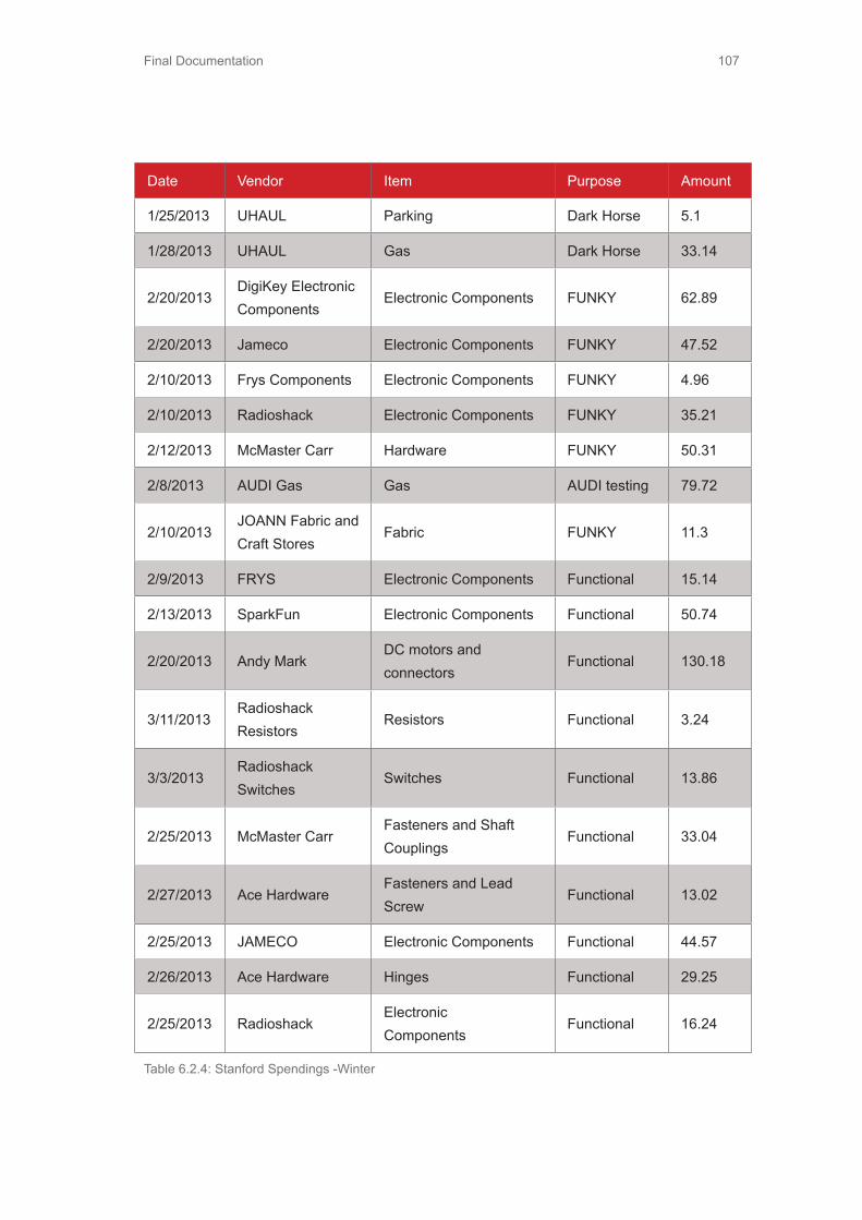
Final Documentation 107
Date Vendor Item Purpose Amount
1/25/2013 UHAUL Parking Dark Horse 5.1
1/28/2013 UHAUL Gas Dark Horse 33.14
2/20/2013DigiKey Electronic Components
Electronic Components FUNKY 62.89
2/20/2013 Jameco Electronic Components FUNKY 47.52
2/10/2013 Frys Components Electronic Components FUNKY 4.96
2/10/2013 Radioshack Electronic Components FUNKY 35.21
2/12/2013 McMaster Carr Hardware FUNKY 50.31
2/8/2013 AUDI Gas Gas AUDI testing 79.72
2/10/2013JOANN Fabric andCraft Stores
Fabric FUNKY 11.3
2/9/2013 FRYS Electronic Components Functional 15.14
2/13/2013 SparkFun Electronic Components Functional 50.74
2/20/2013 Andy MarkDC motors andconnectors
Functional 130.18
3/11/2013RadioshackResistors
Resistors Functional 3.24
3/3/2013RadioshackSwitches
Switches Functional 13.86
2/25/2013 McMaster CarrFasteners and ShaftCouplings
Functional 33.04
2/27/2013 Ace HardwareFasteners and LeadScrew
Functional 13.02
2/25/2013 JAMECO Electronic Components Functional 44.57
2/26/2013 Ace Hardware Hinges Functional 29.25
2/25/2013 RadioshackElectronicComponents
Functional 16.24
Table 6.2.4: Stanford Spendings -Winter

Final Documentation108
Date Vendor Item Purpose Amount ($)
2/22/2013 Frys Electronic Components Functional 40.03
2/22/2013 TAP Plastics Plastic sheets Functional 108.85
2/22/2013 ACE Hardware Fasteners Functional 33.48
2/22/2013 Radioshack Electronic Components Functional 15.15
2/13/2013 Staples Easy button Functional 7.58
2/20/2013Microsoft Store
KinectGestureRecognition
150
2/10/2013 Olive Garden DinnerFood for SUDS
390
Table 6.2.4 - Stanford Spendings -Winter

Final Documentation 109
Balance (EUROS)Type/Name Date Amount (EUROS)5833.33 Bearings 8.4.2013 475786.33 Teflon pipe 10.4.2013 26.045760.29 Force sensors5760.29 Stainless steel pipes 5.4.2013 40.35719.99 Rubber matt 17.4.2013 4.465715.53 Aluminum blank 17.4.2013 43.595671.94 Galaxy tab 2 27.4.2013 449.95222.04 Steering wheel for PC app 3.5.2013 3.995218.05 Stainless steel pipes 25.4.2013 4.095213.96 Spring presser M10, small ball head 26.4.2013 45.755168.21 Spring presser M10, big ball head 3.5.2013 38.565129.65 3D printing SW 12.5.2013 413.134716.52 ACE hardware 13.5.2013 63.194653.33 ACE hardware 16.5.2013 41.944611.39 1/4 '' Duron 14.5.2013 6.174605.22 gearbox 17.5.2013 3744231.22 home depot 18.5.2013 23.254207.97 tshirts 20.5.2013 283.473924.5 carpet 21.5.2013 476.723447.78 ACE hardware 22.5.2013 443403.78 Jameco electronics 22.5.2013 144.683259.1 home depot 24.5.2013 83251.1 ACE hardware 25.5.2013 22.293228.81 home depot 29.5.2013 178.43050.41 projector 30.5.2013 115.262935.15 Ribbon pieces 30.5.2013 1010.161924.99 miscellaneous product 31.5.2013 9.191915.8 Home depot 30.5.2013 8.551907.25 Home depot 30.5.2013 8.021899.23 Home depot 26.5.2013 15.371883.86 ACE hardware 29.5.2013 20.91862.96 ACE hardware 29.5.2013 17.41845.56 ACE hardware 30.5.2013 11.691833.87 Home depot 2.6.2013 95.411738.46 ACE hardware 2.6.2013 14.51723.96 coals 1.6.2013 31.061692.9 Home depot 28.5.2013 26.271666.63 Home depot 6.5.13 28.081638.55 potography rental 1.6.13 51.261587.29 Repeater cable 27.5.13 25.551561.74 Poster 4.6.13 100.411461.33 Ace hardware 5.6.13 19.231442.1 Fry's 5.6.13 25.111416.99 Ace hardware 19.5.13 30.111386.88 Jo-‐Ann Fabric and craft 19.98
Total 4466.43
Table 6.2.5 - AaltoSpendings - Spring
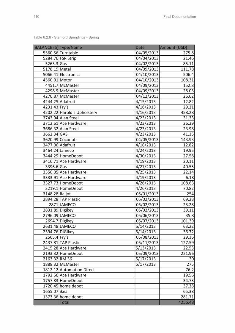
Final Documentation110
BALANCE ($) Type/Name Date Amount (USD)5560.56 Turntable 04/05/2013 275.85284.76 FSR Strip 04/04/2013 21.46
5263.3 Gas 04/02/2013 85.115178.19 Metal 04/09/2013 111.785066.41 Electronics 04/10/2013 506.44560.01 Motor 04/10/2013 108.31
4451.7 McMaster 04/09/2013 152.84298.9 McMaster 04/09/2013 28.03
4270.87 McMaster 04/12/2013 26.624244.25 Adafruit 4/15/2013 12.824231.43 Fry's 4/16/2013 29.214202.22 Harold's Upholstery 4/16/2013 458.283743.94 Alan Steel 4/23/2013 31.333712.61 Ace Hardware 4/23/2013 26.293686.32 Alan Steel 4/23/2013 23.983662.34 GAS 4/23/2013 41.353620.99 Coconuts 04/05/2013 143.933477.06 Adafruit 4/16/2013 12.823464.24 Jameco 4/24/2013 19.953444.29 HomeDepot 4/30/2013 27.583416.71 Ace Hardware 4/19/2013 20.11
3396.6 Gas 4/27/2013 40.553356.05 Ace Hardware 4/25/2013 22.143333.91 Ace Hardware 4/19/2013 6.183327.73 HomeDepot 4/26/2013 108.63
3219.1 HomeDepot 4/26/2013 70.823148.28 Rajjot 05/01/2013 2542894.28 TAP Plastic 05/02/2013 69.28
2871 JAMECO 05/02/2013 23.282831.89 Digikey 05/02/2013 39.112796.09 JAMECO 05/06/2013 35.8
2694.7 Digikey 05/07/2013 101.392631.48 JAMECO 5/14/2013 63.222594.76 DIGIkey 5/14/2013 36.72
2565.4 Fry's 05/08/2013 29.362437.81 TAP Plastic 05/11/2013 127.592415.28 Ace Hardware 5/13/2013 22.532193.32 HomeDepot 05/09/2013 221.962163.32 RM 36 5/17/2013 301888.32 McMaster 5/17/2013 2751812.12 Automation Direct 76.21792.56 Ace Hardware 19.561757.83 HomeDepot 34.731720.45 home depot 37.381655.07 ikea 65.381373.36 home depot 281.71
Total 4256.48
Table 6.2.6 - Stanford Spendings - Spring

Final Documentation 111
6.3 Distributed TeamManagementBearing with 10-hour time difference and different timetable, the team decided to work on different CFPs. The Aalto team tried to create a way for easy manual steering, and Stanford focused on the smooth steering transition between manual and autonomous driving modes. The two teams meet once or twice a week for 30 - 90 minutes on Google+ hangout to keep each other posted on current progress, to share ideas, and to show prototypes. (Table 6.3.1)
Tools Purpose
Emails Contact liaison, schedule update, important file sharing
Flowdock Picture updating, file sharing, showing prototypes
Google Docs Documentation, data recording
Google+ HangoutDiscussion, brainstorming, job division, idea sharing, weekly update
Facebook VW-Audi GroupFinnish team internal group for scheduling, quick questions, idea sharing
Photos Recording testing process, capturing inspiration
Videos Documenting tests, conversations, and prototyping
WhatsApp GroupFinnish internal group for instant chat on schedule confirmation and daily accident report
Dropbox Stanford internal group for file sharing
Table 6.3.1 - Comunication Tools
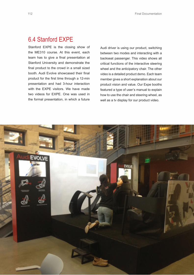
Final Documentation112
6.4 Stanford EXPEStanford EXPE is the closing show of the ME310 course. At this event, each team has to give a final presentation at Stanford University and demonstrate the final product to the crowd in a small sized booth. Audi Evolve showcased their final product for the first time through a 12-min presentation and had 3-hour interaction with the EXPE visitors. We have made two videos for EXPE. One was used in the formal presentation, in which a future
Audi driver is using our product, switching between two modes and interacting with a backseat passenger. This video shows all critical functions of the interactive steering wheel and the anticipatory chair. The other video is a detailed product demo. Each team member gives a short explanation about our product vision and value. Our Expe booths featured a type of user’s manual to explain how to use the chair and steering wheel, as well as a tv display for our product video.

Final Documentation 113
6.5 Future WorkThe team has identified future opportuni-ties that this final system has the potential to include if future iterations were to be made.
Force Sensor Calibrated Driver PresetsThis chair calibrates using the force sen-sors to determine what body type you most likely are from your default seated force readings. Based on these, the chair could determine who exactly is sitting in the chair and adjust the driver presets accordingly. That way the need to input if you are driver number 1, 2 or 3 like in today’s car settings is eliminated and the chair simply knows based on you sitting in the chair.
Similarly if the driver is calibrated as a shorter person, then the chair can lower so that the user will be able to have their feet reach the floor and pedals without having to do any manual adjustments. This will make it much easier for shorter people be able to utilize the foot pad for moving their chair forward and backward. This can be applied to taller people as well who may need the chair raised up and moved backward in order to reach the wheel and foot pad comfortably.
These presets can be extended passed just chair adjustments to mirror adjust-ment, temperature control, lighting control, and even media/ radio preferences. This will ultimately make the car know who is sitting in the car without the user ever hav-
ing to indicate who they are. The car will become smart and be able to anticipate the driver’s every need.
Reconfigurable Chair LocationsThe team sees a potential for getting that fourth chair back into the cabin space. It is possible to put all of the chairs on a railing system so that the chairs can move around. If there are only two people in the car then the driver’s seat can move to the left and the back right seat can move forward. That way the two passengers are seated next to each other. Similarly if there are four passengers than the right back seat can move forward, and another seat be unfolded from the cabin space to replace the seat that was just moved forward. We think that this will allow for more mobility and flexibility for users in the cases were this three seat configuration may not be optimal.

Final Documentation114
6.6 Personal ReflectionsSangramFall ReflectionI think registering for the ME310 sequence before I graduate from Stanford was the best decision throughout my stay here. It is now that I know what I would have missed if I had not taken 310 this year. Its been a great learning experience for me and I am enjoying working with my team at Stanford and the global team as well. It is still amazing how we managed to get so much done in just over a month since serious work on the project started. There were times when we were completely lost and there were times when we knew exactly what we wanted to do. The former was required but was completely outside my comfort zone. That is one important thing I have learnt this quarter - how to deal with total ambiguity.
Everyone can manage to think about something to do for testing and benchmarking, but I think the most important part and the one at which my team is very good at is sitting down and analyzing the observations and getting tangible conclusions from the tests that were done. I have found these intense “what-is-going-on” discussions to be the most useful for me as well as for the team. Observing and thinking about everyday situations and drawing parallels into the technology and situations that will exist in the future is something which will prove to be very useful while heading towards a final solution in spring. I think this year team Audi has a great opportunity to create and design for a unique experience for futuristic cars and I am looking forward to getting back to work in January.
Winter ReflectionThis was an interesting quarter for me. We went through some great prototypes which gave us good insights in the design space. It took long hours of work to get our prototypes ready in time and functioning properly, but our team effort was very good and we got things done! The best part is that I am enjoying working on this project so much that I did not even realize how this quarter went by. It was when I started considering other things as being interruptions to 310 work that I realized how important this project has become to me. We have come up with a very good direction for our project. I still keep wondering if there is any other good idea out there, which is why I wish we had done a couple of more dark horse prototypes. I also think that our communication with the global team could have been better and we as a team would have discussed not only the idea for the next prototype but how each of the teams is planning to implement and test that idea. In any case, I am excited for the Spring quarter and slightly scared after looking at how quickly the next deadlines are coming up. But I am very sure that we can get there. I am looking forward to a good final brainstorm with our team in Finland during Spring break and hope that we come with a solution directly based off all the good insights we have over the last two quarters.
Spring RelfectionI have a lot of mixed emotions when I write this reflection. ME 310 has been everything that I had hoped for and more. It is remarkable what we have achieved as a team. The final product we have delivered

Final Documentation 115
“ I am enjoying working on this project so much that I did not even realize how this quarter went by.”
speaks for itself but the journey is something which does not come across and is not so apparent. It has been a tireless effort for the whole year. The team went through ups and downs and we survived it to probably become one of the best functioning teams in 310 this year. I think our Finland trip was the game changer. We realized that more than half of our issues were communication issues and we went from scattered thoughts here and there to a strong unified vision and a solid plan as we got into the spring quarter. I enjoyed the design and exploration phase as it was something new to me and I really learnt a lot of things in the first two quarters. Not to say that I did not learn anything in the last quarter, I learnt a lot but I was totally in my comfort zone in Spring. We have ultimately implemented everything at a very professional level and have finished what we set out for. I wish we had the planned our budget more properly so that we could have directly invested at the beginning in
teammates who have become such good friends that it is not easy to say goodbye to them as they leave one by one. It is time to say goodbye to Stanford. It has been one awesome ride and the AUDI project has been the best experience so far, learnings and moments that I will cherish for the rest of my life. It is not the end of 310, this is just a new beginning for 7 people who I am sure will carry forward this experience and achieve great things in life.
StephanieFall Reflection
As fall quarter comes to a close, it is clear that being in a state ambiguity is a fact of life in ME 310. Our team began extremely enthusiastic about the prompt and utterly overwhelmed by the amount of things we knew nothing about. It has been difficult thinking about designing more than 20 years in the future. Deciding on what to assume and how to even come to those conclusions about the future has been a long process involving long discussions and debates within our Stanford team and with our global team. I hope we will get the chance to do more wild brainstorming next quarter, since this quarter the assignments often times seemed to hamper our ability to really get creative.
Furthermore, collaborating and
communicating with the global team has presented many challenges. Scheduling meeting times and working around 7 people’s schedules has been difficult, though I think we have gotten better at it. Also the collaboration problem, I believe has
the changes that we made towards the end. But it was all a learning experience and I am glad I went through it. That being said, it is now time to say goodbye..to the loft, to our space, to my

Final Documentation116
tasks so that things just get forgotten on our to do lists. Generally, this quarter has been a lot of fun and I can’t wait to see how our project evolves over the next quarter.
Winter ReflectionThere are many emotions that come to mind when reflecting on this quarter: excitement, frustration, confusion, clarity, and, well, exhaustion. We began unsure of what we were doing and what direction we were headed, but after diving into Dark Horse everything seemed to begin to make sense. I was excited about what we were learning and the experiences we were creating and testing. The time has gone by so quickly and we never let up to catch our breath, but I think that is what has made this quarter so interesting. We were always working our way through a maze of problems or decisions that needed to be addressed. The difficulties were in figuring out how to communicate everything we were learning with our global team. Despite more weekly meetings and being in constant contact, we seem to have moved from a unified vision last quarter to a very disjointed and slightly at odds vision for where to get next. I also found it hard to get out of the technical mindset of implementing our prototypes. It was easy to be overcome and overwhelmed by all of the technical components that needed to get done and put off making sure that the experience and needs for the user are always at the forefront. I am excited to see where we are headed next and to visit Finland to spend more time with our global team.
“ ...this has been the best course I have taken so far ”
in large part been because of the difference in assignment due dates. For a large portion of this quarter, the global team’s assignments were due about a week after ours. This made it difficult to brainstorm ideas together and really talk to each other and learn from each other’s assignments, in order to better inform each team’s understanding of the design space. When both teams were together, the brainstorming sessions were fun, innovative, and inspiring. I really appreciated everyone’s creative ideas and hope we will come together more often in the coming months.
Prototyping and making an experience come to life is, for me, the most enjoyable part of the process. I like being able to touch and see an idea that was born from our brainstorming, and I enjoy seeing how other people react and respond to that
physical manifestation of the idea. Even quick prototypes and experiments made our work feel more real and tangible, and it took us out of our own heads. Instead of getting lost in a debate, we could not deny what we were actually experiencing and seeing while using the prototype or in the experiment. I think both teams can improve how we communicate and divide tasks, making people at times individually responsible for

Final Documentation 117
Spring ReflectionThis quarter was certainly crazy, but it was nice to finally just get to focus on building out our ideas. As expected, we ran into many challenges that we didn’t anticipate, but I think we handled it well. Everything seemed to go wrong, but we kept going. I was super impressive by everyone’s persistence. It was also much easier to get things done and make significant progress on our project once the whole team was together. We were able to divide and conquer. We supported each other and made sure that if someone needed help they got it. Overall, I am extremely happy with how our project turned out, despite the consistently long nights. While not every part was designed or made perfectly, the really challenging parts we figured out and the entire experience we hoped to deliver, we delivered. This class has been a great exercise in communication, balancing a tight budget and time schedule, and designing something so far in the future that the problem doesn’t yet exist. I have loved this class and I am happy to have met and learned from my teammates.
DavidFall Reflection
This design project has been challenging and exciting. Since the project proposal is set for the year 2035, being able to predict and assume what the future will be like, in terms of the automotive industry but also the lifestyle of humankind, is extremely difficult. I took this course to challenge me and be able to apply my electrical engineering and creative thinking to solve a wide-open
problem. Being able to design something and physical show a final product at the end of it all is a rewarding experience.
The collaboration aspect with students from another country and that have different backgrounds has been an eye opening experience. I have not collaborated with a group from a different country and being able to effectively and efficiently communicate with each has been a struggle. A major advantage with this collaboration is being able to see different perspectives of the same idea from mechanical engineers and product design engineers have opened up solutions that I probably would not have noticed myself as an electrical engineer. I have learned so much from my team members about different areas of engineering.
I believe that at the end of the course, I will become a better engineer that has experience and expertise in areas that I probably would not have been involved in outside of this design class. I am definitely looking forward to the next two quarters and being able to see all the hardwork and long hours paid off from the final design built.
Winter ReflectionThe winter quarter has been extremely exciting. Since the fall critical function prototype and working on the darkhorse prototype, the direction and logic of going from prototype to prototype has been well defined. It has been great working on the

Final Documentation118
prototypes although it has been very time consuming and stressful at times. Being able to see our hard work pay off and our concept starting to look more like a real product gets me looking forward towards the spring quarter. There were many difficulties with communication between our global partners but we have been more persistent in keeping each other in contact on a bi-weekly basis or so. Our trip to Finland to converge and decide all the details on the final design will be challenging due to all the opinions of the team members but I am positive that we will work together and ultimately pull off a spectacular product to show off at EXPE. I am more of a technical person so I am definitely ready for the spring quarter to start to make our vision a reality.
Spring ReflectionME310 was an amazing experience. This spring quarter was extremely intense but we managed to complete all the goals we set. I learned so much from my local teammates as well as my global teammates. ME310 is a class that I have never experienced before nor would I have experienced if I did not come to Stanford. It is much better than any typical electrical engineering class that I have taken. I collaborated with some of the smartest people in the world and I was fortunate enough to learn valuable skills from them, but also give them some of my knowledge from past experiences. Prior to the spring quarter, the Stanford’s team dynamics and communication with the Aalto team was little to none. But once we visited Finland, had some quality team
bonding, and set our sights to deliver a final design that has never been seen before, our team became stronger and supportive than ever. This class has taught me that communication on all basis is one of the keys to success regardless of how close or far away you are. Although I am ready to graduate from Stanford and excited to learn more from real world experiences at my full time job, I will never forget what I have learned and experienced from ME310 and my teammates. My team is amazing and I am very glad that I was able to share this experience with them. In the end, AudiEvolve was a success because of the hardwork, dedicated, supportive, and optimistic attitudes of each of my teammates. We are AudiEvolve, transforming the journey into the destination.
GoranFall Reflection
Before I took this course, I didn’t know what to expect. It was the first time for me to take a course from another department and I was really worried. This course is one year long and if it doesn’t meet my expectations, I would be stuck there for the entire year. Fortunately for me, so far the course was amazing. I feel like I am learning a lot for the first time since I came to Aalto and I hope it will continue to be like that until the end of the course. I have to mention that I was positively surprised by the teaching team, especially Harri. It seemed like he never stops working. Whatever was the problem, he solved it as soon as possible and even showed personal initiative which

Final Documentation 119
is unfortunately very rare among professors. I think it is really interesting that people who recently finished the course are the ones that are teaching you. Their knowledge is really fresh and it is very easy to talk to them.
The project we got is inspiring. Thinking that far ahead in the future makes you come up with different and often shocking concepts. It requires a lot of research in order to understand the future and how might the world evolve, but I always liked watching scientific shows and science fiction movies and this part of the project I really enjoyed.
This course also teaches you to try and test. We did a lot of tests, but I still feel that we should have done more. By observing and testing we were able to identify some problems we overlooked. It was a shame that to this date we haven’t tested any of our “out of the box” ideas. We had a plan to test those ideas as soon as we come back from our winter break.
Working in interdisciplinary team is a new experience as well. Sometimes it was hard to make a decision, but most of the time it was fun. Although my teammates are not from creative fields, in brainstorming I was surprised how fast they relaxed and the number of interesting ideas we got in a short period of time surpassed all my previous brainstorming experiences.
As a conclusion, so far this course is more than a positive experience. We still have a lot of work before the final presentations. I just hope that the reaction from our client at the end of the course will be positive as well.
Winter ReflectionBeing a part of this course so far has been an interesting experience. I’ve definitively learned a lot and I have to say that this has been the best course I have taken so far. Maybe the assignments that we are doing are not so new for me, but the their number and intensity definitely are. Every week I am thinking that after these few days I can take a small brake, but it just never comes. Winter quarter has gone very quickly. It has been very stressful period. Almost through the entire period we didn’t know what to do. It is still very confusing. The end is approaching and decisions need to be made, but we are still struggling with our focus and the problems we are solving. I wouldn’t want to deliver something at the end that doesn’t satisfy me. The course takes eight months and it would be a waste if I can’t put the project in the portfolio later. It means that the concept needs to be strong and the visuals as well. I realized through the course that in the case we have not enough time at the end, which might happen, that design is going to suffer. Concept needs to work and that is something required from us. It needs to look appealing also at the end, but the number of engineers and designers in the group is so unbalanced that it will be a struggle to convince people of the importance of aesthetics when we approach the final deadline. I am really scared that I might not be able to show this project to future employers at the end.
Team work improved during this period. We were equally “lost” when it comes to

Final Documentation120
the concepts and ideas. That is maybe the reason why we stopped discussing and arguing so much. It looks that we are all scared about the final outcome of the course. We have now much better communication with our global team as well, but it still feels that we are competing in a way. I know that will improve during the spring. I am looking forward to the end of the course. Not because I will have more free time, but because I can’t wait to see our final result. I hope it will make me proud and that my final reflection will be filled with satisfaction.
Spring ReflectionWe knew that we need to meet soon in order to clear all the differences between our two subteams and Stanford student visit to Finland helped us become one team and to clarify our main goal and vision. It was a very intense discussion and we had a lot of disagreements but at the end we found a compromise and we all felt excited about the final two months.The final two months were very hard. We worked a lot to fulfill our vision, but everything seemed not to go according to our plan. Simply put, whatever that could have failed, failed. At some point it looked almost impossible to pull this off. At the end, we had to make some cuts, for example removing windshield from our plan, but we managed to make all the other components. My task in the final prototype was making the cabin space which included steering wheel, dashboard and the ribbon. The dashboard itself took more than two weeks to built. I believe we took the worst possible
way to make it, but at the end it saved us a lot money that we used to outsource cutting of acrylic pieces. I believe this course is the most intensive, but in the same time the best course I have ever taken. I strongly believe I have learned a lot during this eight months especially in the communication sense. I also started doing more fast prototypes and for a designer it is very valuable habit. Honestly in design part we could have done more. Some of the parts were really not on the level expected for design professionals, but in the given time frame and the scale of our project, maybe that was the maximum we could have done. For the end, I would like to thank everyone in the teaching team for making this course so amazing. I know they made it the way it was and I really wish in the future the course will keep its culture and cult status. Also many thanks to DF staff for helping us numerous times. I am really proud to have been a part of this great group of people. With that I mean everybody involved in the course and DF. I know that wherever I proceed in my life I will always come back to this year as one of the best and most fun years of my life. Now it is time for something new. Over and out!
SifoFall Reflection
The Fall period is all about dealing with ambiguity. Our project is solving a problem after 20 years. I feel we were walking in the dark tunnel, expecting to see dim light from far away. It’s not as bad as it sounds like. In

Final Documentation 121
fact, once we started to observe real life, to dig into current problems, and to embrace new concepts, we felt we would become successful future fortune tellers.
As the project goes on, I have got two biggest learning. The first is we should prototype more other than spending time discussing whether the idea is good or not. I enjoy working with this team. My favorite part is brainstorming, when crazy, funky, weird ideas are generated from people coming from 4 different majors and 5 different countries. Appreciating each other’s ideas and building ideas upon each other’s is definitely a good learning process, and it’s difficult. We started from fighting which idea we should test out, which hindered our creativity and efficiency. The second learning is constantly asking myself what is the reason behind the “supposed obvious” to dig out the user’s real need. I didn’t realize fun driving also means letting your car reach a challenging status that you can never achieve in real life. I didn’t know separating steering control and turning control in different devices is actually easier than combining them in one. Thanks to the project, I paid more attention to daily routine and details. The result is beneficial.I wish in the next period, communication between two sub teams can be more frequent and collaboration can be more productive. I wish we can test out more crazy ideas and leave no regret before the project ends.
Winter RefletionWinter period is all about learning. Started
from learning Arduino for the robot, I found coding extremely interesting. The movement of servo gave me immediate feedback on whether my code is correct or wrong. It was my first time to code for electronics and to plug sensors, servos, LEDs to teensy board. Connecting all of them in 10 days for an amateur like me was challenging. Thanks to the help from Design Factory staff, it shortened my learning curve. Lesson from this, sometimes we need to think big, with “can-do” spirit.
In winter I found travel brought the team together. When we were in Germany, the team helped each other in trivial things. We had to spend all time together, so we got time to discuss something that had never been discussed before. Running to catch the last minute morning train, putting on earphone whenever one was in toilet, de-briefing in the noisy metro, amazed by the robots and became speechless in Audi factory, sitting anxiously to express what we had been doing to Audi faculty, these are valuable moments that make the team more gathered and more open to a bold vision.
In winter I noticed communication is the key. Especially between two global teams, we need to spend more time on that. I noticed our past communication strategy (hangout once a week and one on one session once or a week) is not enough. There are still things not agreed by both teams. There are conflicts we two teams haven’t gone through. There are important decisions we haven’t made together. Brainstorming
Final Documentation122
through Google hangout was not engaging. To talk about disagreement, any other communication tools than face to face can’t fully handle the friction between two teams. I look forward to having Stanford team in Helsinki. I wish we’ll talk openly and come up with something awesome.
Spring ReflectionME310 gives me the best learning experience ever. Looking at our final product, I’m extremely proud of our team. It looks just like the rendering we had one month ago. To be honest although we aimed high, I couldn’t believe we can realize it in a generally perfect way. The past month was so far the busiest time of my life. We worked around the clock to get things crossed from the to-do list. The teamwork with Stanford students was pleasant. We supported each other whenever whoever needed help. Although we have two separate products, the integration work was done very well. The cabin space creation process was full of memories. Although it’s not under critical priority, it definitely was a critical “nice to have” and affected the whole EXPE experience. We experienced failure with the chair rotation, frustration when dashboard cracked in the painting stage, and desperation when the ribbon completely broke and we almost tried every possible way to bend it. It seems that we had all possible failures in the last month, but the important thing is, we overcame all of them. I’m glad that we never gave up being persistent and creative.
310 is definitely my favorite course and I will remember the project, the people, the awesomeness forever. I’m grateful for the so much help received from our teaching team and Defa people. As a business student I’m probably the person learnt the most in this team. Trying to find my own role in this extremely technical project was quite a journey. The largest learning goes to cross-functional communication and multicultural communication. I enjoyed realizing ideas with fast prototypes, proud of getting hands dirty and being a workaholic. If I have to say wishes, I wish we could have more user testing and more realistic planning of time in design perspective. Thank you ME310! I’m ready to continue the awesomeness.
TommiFall Reflection
This project has been quite different from the paper bike challenge. This is mainly because of the vague brief and its million opportunities to go for. Organizing ourselves took a lot of time in the beginning and there is still something that could be done better. For example setting up internal deadlines and plan them more precisely beforehand. This is something that is quite different from worklife since there is no individual who organizes and who is responsible for all the actions.To get working done efficently globally is still a puzzle to solve.
So far the project has taught me mainly social skills and teamology. Taking also into account the cultural differences and personal preferences has taken a bigger picture in team working. This is quite
Final Documentation 123
different from the previous studies that involve only substance learning like math and physics. These kinds of social skills are essential in real work life situations and it is good to practice it in different situations and this kind of project based course with diverse team is excellent opportunity for thatThis project has also made me put a lot of thought into the future technology and future world, and I have a feeling it is really going to be quite different than today. But before really digging into it, I really had never thought about it. What it comes to autonomous cars, I had never even thought about that possibility even though I am a hard core car enthusiast (maybe that is also the reason for that).What it comes to this documentation, I really think that content could be somewhat different from the final documentation, especially the design specification/description part. Since we do not really have a concept to go for, why do we have to artificially made something into that section? Critical prototypes are only testing some of the functions or some experiences, and therefore they are not even close to the initial prototype.
Winter ReflectionThis winter period has been even more chaotic than the fall period, at least I feel so. We have been using increased amount of time on debating about philosophical concepts without actually putting them into practice. All the ideas seem to be “easy” to put into practice and not different and innovative enough. Therefore we end up
with quick and dirty prototypes basically every time. Latest prototype was a good example that proved that even the “simplest” idea takes quite a lot of time to actually put into practice and there will be most likely be some unexpected obstacles along the way.
I personally like our vision we have at the moment, even though it still needs some polishing. Anticipatory sensing chair is a good concept but my opinion is that it needs a proper story around it. Freedom within the cabin space does not add any extra value for the user, if there is no reason to change position.Team dynamics seems to have some issues locally and globally. Somehow local working seems to be highly inefficient and I do not know the reason why. Globally we have some communication issues and difficulties to agree with a common decision. We have been trying to solve our local issues but somehow it just does not seem to ease up. What comes to the global problems, I think our time together in Finland is going to be the cure for that.
Spring ReflectionThis period was absolutely the best! Our concept started to make sense and we were able to make solid common opinion about our project’s framework and what we are about to make.It was the turning point of our project, when Stanford student were allowed to come to Finland. Then we finally realized what we will do, even though it took meant skipping our spring break, but it was totally worth it.

Final Documentation124
The next big event was our trip to Stanford! Then all the actual execution happened! Days were sick-long, but hey, we made it! The final outcome was extremely awesome and it was so nice to hear all the good feedback.
All in all, ME310 was the turning point of my life. This was easily to most demanding school challenge, and maybe, the most demanding challenge in my life! It taught me a lot of stuff about human interaction, attitudes and ways of thinking, that normal school courses cannot teach. All I wonder now is, how will my last school year go, since it will be dramatically different than this one.
In the end I want to thank my awesome teammates, our TAs, our coaches, our liaisons, and DF staff, without you, the magic would not have happened! You made my year the unique ME310 experience that everybody were blabbering about in the beginning. Thank you once again!
Heikki
Fall Reflection
I have always been good at time management and figuring out how to do things. Now, it has all changed! I keep slipping off my deadlines and coming to meetings unprepared. Work is not an excuse, but it makes things harder. I am really looking forward to the next year where I have less things to do and more time to focus on ME310.The greatest learning has been anyway in communications. There has been several
misunderstandings during the course and I have been finding myself frustrated but also surprised about the way our team has globally communicated. Skype and Google+ with 10 hour time difference is certainly a challenging setting. It is easy to forget that if you do not have the physical presence of your colleagues, the electrical representation is everything the counterparts sense out of you. That is why everybody should feed all the time their doings to other members of the team. Trust becomes with understanding and understanding starts from the knowledge you share. I have not managed to do this by myself either. On the other hand, I tried how does it work if I feed information of our tests to our Local ME310 Facebook group and found a significant difference. Generally in our Loft there is a certain feeling that Audi team is doing a lot of work. One piece of this reputation might have been earned by active communication. I wonder if we should take this into account and start doing it within our global team too, both ways? Once we had a small reflective meeting together in our local group and it felt really good to actually hear what people think in peaceful environment. I always wonder what other people think in order to adapt myself for the best of the group. I really wish we can say after the project that we have been one unite team that succeeded in because we were bold in communicating.
To get information of how people behave in certain situations, observation is the most usable tool. We tried not only to focus on superficial behavior, but finding behavior that repeats itself and that differs from
traditional behavior.

Final Documentation 125
Winter Reflection
In winter quarter we reached our first global communication issues. It felt that earlier every problem was something lighter and easy to solve by conversing. In the end of this quarter we found two separate groups striving for separate goals. I was acting as a communication responsible between global communications and there I was able to understand more where the other part of the team stands. After switching the responsibility I was more and more lost and it felt that less communication effort was made. We also started using WhatsApp program in our mobile phones, which had more of positive effect on our group work. We were able to see with less latency what was happening on the other side of the world with pictures and videos.
In our local communication there was less organization. There was no sufficient driver that we would have done anything especially when Tommi was away. No todo lists were made nor followed.
In the end I was happy to finally contribute on technical prototype and were able to build and code one fully functioning system. I think it did good for our team to see how much effort and details are to build one single prototype until the end.
I am still not happy with our last concept idea. It feels that is not ambitious enough and does not cause an “wow” effect every time. I am really looking forward to get the other half of the team to Finland in order to
discuss and be on the page of the project. I also wish we could build our prototype in a moving car. Maybe there is too little time. I hope I am wrong.
I have not heard about our corporate liaison for several weeks now. There is definitely room for improvement. We also will see our Europe liaison during the spring break and then will be able to discuss further about our
ideas for the final port.
Hopefully we will get a new start after the Stanford’s visit and will be able to nail the final prototype concept during the visit.Spring ReflectionAs anticipated, hard work before and especially during the Stanford visit paid its dividends. We came together and discussed through our vision and felt united again. Only levels of expectations were a bit different among people. All in all it was clear that there was so much to do before the whole prototype was to be ready in the Design EXPE in Stanford. After Stanford left we knew what we wanted to achieve and we started exploring different ways and ended up trying “Magneto” concept and retraction mechanism parallel. In the end we found out that compromise between these two would suit best to our overall concept and story.
I was responsible of making interaction happening in the final prototype. That meant I had to suggest and figure out what would be suitable level of execution of working, entertaining and future interaction for the project, but also then make it happen. I like
Final Documentation126
challenges and me not having that much of coding experience and inter-machine communications I started took a look into things I have liked to learn but never have had a legitimate reason to dig into. I don’t mind hard working, I have done a quite a bit of physical and boring stuff, which is not challenge anymore, and now very much enjoyed working under pressure without any clue if I was going to succeed with the tasks at all. All the thousands of lines of googling and aha -moments will stay in my mind.I was so much looking forward to come to California and enjoy being responsible for only one thing at the time. Before flying over, at the same time with ME310, I was spending nights at my work while having part of the responsibility of our teams performance. It was not fun at all. I have learned that two major things I care about seems to be maximum I can have on top of each other.

Final Documentation 127
7. Appendix

Final Documentation128
7.1 Initial Brief
!!"#$!%&'()*+,$-!./&01!&2!34$/56+!789:;!1/&<$6=!2&/!=#$!>;:>?>;:9!+6+@$456!A$+/!5)!
&-!=#$!=&156!&2!+0=&-&4&0)!@/5B5-,!+-@!=#$!5-=$/+6=5&-!C$=*$$-!+0=&-&4&0)!6+/!+-@!
#04+-!@/5B$/D!!"#5)!1/&<$6=!*5''!C$!6&41'$=$@!5-!6&''+C&/+=5&-!*5=#!3+'=&!E-5B$/)5=A!5-!
F$')5-(5G!H5-'+-@D!
!
IJ=!5)!=#$!A$+/!>;9K!+-@!+0=&-&4&0)!1+))$-,$/!B$#56'$)!6+-!1/&B5@$!@/5B$/)!*5=#!
5-6/$+)$@!2/$$!=54$!+-@!+!)+2$/!@/5B5-,!$L1$/5$-6$!*#5'$!)=5''!1/&B5@5-,!=#$!&1=5&-!&2!
4+-0+'!6&-=/&'!52!=#$!@/5B$/!@$)5/$)D!!M/$+=$!+!6+C5-!=#+=!5)!!"#$%&$'%()#&*!5-!&/@$/!=&!
1/&B5@$!$-=$/=+5-4$-=!&/!*&/(5-,!)1+6$!2&/!=#$!@/5B$/!@0/5-,!+0=&-&4&0)!6&-=/&'!+-@!
)=5''!$-)0/$)%+,#%'*-.#*%+*/0+0%+,#%(&*10%&/+!$!2!/0%3/$(+-!$04!A$=!6+-!+')&!
1/&B5@$!+!2#&$0%3!*%(!$+*!))-$5%+,#%(&*!52!=#$!@/5B$/!6#&&)$)!=&!=+($!4+-0+'!
6&-=/&'DN!
!
"#$!&0=6&4$!&2!=#5)!1/&<$6=!)#&0'@!4+-52$)=!5=)$'2!+)!+!1#A)56+'!1/&=&=A1$D!
!
M&/1&/+=$!O5+5)&-!
"/$B&/!P#+--&-!
%&'()*+,$-!8'$6=/&-56)!Q$)$+/6#!O+C!
8-,5-$$/G!70'=54$@5+!311'56+=5&-)!"$+4!
6R!S;TD9T;DT:U;!
&R!UK;DTVUDS;U9!
$R!=/$B&/D)#+--&-WB*D6&4!
5/'R!K;;!M'511$/!X/5B$G!Y$'4&-=G!M3!

Final Documentation 129
7.2 Fall Brochure
Project Background
Audi is at the forefront of innovation in automotive technology and
is dedicated to providing customers with elegant sophisticated
solutions. Autonomous vehicles (AVs) will be relatively common by
the year 2035 and Audi envisions car design will focus not only on
the driving experience, but also the riding experience. Important
areas in designing driving spaces for AVs include how people will
interact with an AV and perform activities other than driving. Even
though the future users will be comfortable with riding in an AV,
there will be times when the user will want to take control just to
enjoy the pleasure of driving.
Vision
The design team envisions a future where people will want to
regain time lost from commuting to locations where they would be
productive. The team goal is to create adaptable cabin spaces
suitable for many activites, in order to transform the journey into
the destination.
Team VW-‐Audi envisions driving being a secondary activity that is
performed as frequently as all the other desired activities, such as
working, relaxing, socializing, and interacting with multi-‐media. An
important aspect of this design would be a seamless transition
between any of these activities. The VW-‐Audi team will aim to
maintain the pleasure of driving while providing comfort, safety
and an easy transition that increases situational awareness.
Design Team
Stanford UniversitySangram Patil
Stephanie Tomasetta
David Wang
Aalto UniversityGoran Bjelajac
Sifo Luo
Heikki Sjöman
Tommi Tuulenmäki
Corporate LiaisonTrevor Shannon
CoachJeremy Dabrowiak
Main Assumptions about 2035
Users will already trust and be comfortable with the
autonomous vehicle technology in a normal riding scenario.
Driving will not be turned over to the human driver in
emergency situations. The car will safely come to a complete
stop in those situations.
There will be car-‐to-‐car and car-‐to-‐infrastructure
communication.
Design Requirements
Functional
Seamless transition between any activities
Non-‐intrusive interface to the current
activity
Keep the user aware of the surrounding
environment and the AV’s actions
The control input from the user should
maintain the pleasure of driving and be
utilized as the interaction input
Physical
The cabin has to be
open and have an
organized interior
Personalization of
the cabin space to
each user
Adaptable cabin
space for doing user
desired activities
Opportunities
Redefine the
business model
to one that is
perhaps
subscription
based
Leverage the
social impact
of self-‐aware cars
Design Strategy
Explore user interaction in the context of cabin space transitioning
Better define and categorize activities that would likely be performed in an AV
Identify emerging technologies to integrate into the cabin space based on defined activites
Left: User testing with different steering controllers. Middle: Transition Experience Prototype that utilizes a guided matching task for gradual transfer of control. Right: Cabin Space Prototype of moving chairs.
Critical Function & Experience Prototypes
The team focused their efforts on three main areas: steering, transitioning to driving, and cabin
space. The Aalto Team created multiple prototypes to test how effective and intuitive various
steering controllers are for the driver. The Stanford Team focused on creating an experience for
gradual or direct transitioning to manual driving using a display that prompts the driver to mimic
the control actions of the AV. The intent was to increase the driver’s situational awareness of the
driving scenario they are entering after being occupied by another activity. The team also tested
out a new concept for cabin space interiors that will be more suited for a wide variety of activites
by having reconfigurable chair locations.
Key Findings
Visual representation of interactive information is too intrusive and distracting during driving
even if the visuals are projected into the driving field of view.
People are better at doing multiple tasks at a time if the sources of information needed to
perform the tasks are cohesive or the same.
When prompted to mimic the control actions of an AV, users didn’t feel like they were driving
Stephanie Tomasetta
David Wang
Aalto UniversityGoran Bjelajac
Sifo Luo
Heikki Sjöman
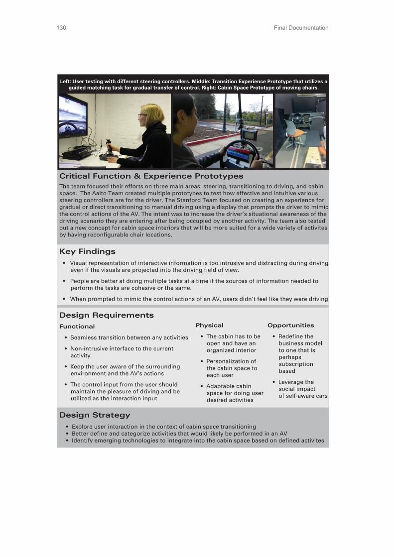
Final Documentation130
Project Background
Audi is at the forefront of innovation in automotive technology and
is dedicated to providing customers with elegant sophisticated
solutions. Autonomous vehicles (AVs) will be relatively common by
the year 2035 and Audi envisions car design will focus not only on
the driving experience, but also the riding experience. Important
areas in designing driving spaces for AVs include how people will
interact with an AV and perform activities other than driving. Even
though the future users will be comfortable with riding in an AV,
there will be times when the user will want to take control just to
enjoy the pleasure of driving.
Vision
The design team envisions a future where people will want to
regain time lost from commuting to locations where they would be
productive. The team goal is to create adaptable cabin spaces
suitable for many activites, in order to transform the journey into
the destination.
Team VW-‐Audi envisions driving being a secondary activity that is
performed as frequently as all the other desired activities, such as
working, relaxing, socializing, and interacting with multi-‐media. An
important aspect of this design would be a seamless transition
between any of these activities. The VW-‐Audi team will aim to
maintain the pleasure of driving while providing comfort, safety
and an easy transition that increases situational awareness.
Design Team
Stanford UniversitySangram Patil
Stephanie Tomasetta
David Wang
Aalto UniversityGoran Bjelajac
Sifo Luo
Heikki Sjöman
Tommi Tuulenmäki
Corporate LiaisonTrevor Shannon
CoachJeremy Dabrowiak
Main Assumptions about 2035
Users will already trust and be comfortable with the
autonomous vehicle technology in a normal riding scenario.
Driving will not be turned over to the human driver in
emergency situations. The car will safely come to a complete
stop in those situations.
There will be car-‐to-‐car and car-‐to-‐infrastructure
communication.
Design Requirements
Functional
Seamless transition between any activities
Non-‐intrusive interface to the current
activity
Keep the user aware of the surrounding
environment and the AV’s actions
The control input from the user should
maintain the pleasure of driving and be
utilized as the interaction input
Physical
The cabin has to be
open and have an
organized interior
Personalization of
the cabin space to
each user
Adaptable cabin
space for doing user
desired activities
Opportunities
Redefine the
business model
to one that is
perhaps
subscription
based
Leverage the
social impact
of self-‐aware cars
Design Strategy
Explore user interaction in the context of cabin space transitioning
Better define and categorize activities that would likely be performed in an AV
Identify emerging technologies to integrate into the cabin space based on defined activites
Left: User testing with different steering controllers. Middle: Transition Experience Prototype that utilizes a guided matching task for gradual transfer of control. Right: Cabin Space Prototype of moving chairs.
Critical Function & Experience Prototypes
The team focused their efforts on three main areas: steering, transitioning to driving, and cabin
space. The Aalto Team created multiple prototypes to test how effective and intuitive various
steering controllers are for the driver. The Stanford Team focused on creating an experience for
gradual or direct transitioning to manual driving using a display that prompts the driver to mimic
the control actions of the AV. The intent was to increase the driver’s situational awareness of the
driving scenario they are entering after being occupied by another activity. The team also tested
out a new concept for cabin space interiors that will be more suited for a wide variety of activites
by having reconfigurable chair locations.
Key Findings
Visual representation of interactive information is too intrusive and distracting during driving
even if the visuals are projected into the driving field of view.
People are better at doing multiple tasks at a time if the sources of information needed to
perform the tasks are cohesive or the same.
When prompted to mimic the control actions of an AV, users didn’t feel like they were driving

Final Documentation 131
7.3 NeedfindingTo get information of how people behave in certain situations, observation is the most usable tool. We tried not only to focus on superficial behavior, but finding behavior that repeats itself and that differs from traditional behavior.
Cafeteria observations
As a part of our observation exercise at Stanford University, we went to the local cafeteria and observed people working in a public space while eating and having drinks at the same time. The reason behind it was to learn about people’s working habits in a relaxed atmosphere. (Figure 69)
Observations• One seated, people rarely change
their initial position, although their seating position is very uncomfortable (Figure 14: Person in uncomfortable position)
• People don’t think about their comfort in advance. They put their bags on the table before they sit, and then once seated, they adjust to the situation. (They worked around the bag on the table instead of moving it to the chair next to them)
• People on more comfortable chairs wanted to make themselves even more comfortable. They placed their legs on the small table and placed laptops on their laps.
Conclusions / Lessons Learned• Interior can dictate user behavior - if
the seat looks comfortable, users try to make themselves more comfortable. In uncomfortable chairs, users don’t care about their comfort
• We can manipulate users and predict their behavior
• Sometimes, users don’t behave in a logical manner
• If we want people to seat comfortably, then our design must express comfort

Final Documentation132
7.4 Benchmarking Gestural steeringAn Xbox Kinect Dance Revolution game was played to learn what it would feel like to drive using gestural commands. The setup involved a TV, an Xbox, and the Kinect sensor module. The sensor module had to be placed and leveled in the correct position to be able to capture all of the movements of the dancer. The distance of the sensor was also important to be able to capture movements from head to toe. Several dance songs were played and points were evaluated to see how well the dancer mimicked the animated dancer’s motions.
Mind ControlThe prototype was set up to play two different games. One game involved two users to compete against each other to move the ball towards the opponent’s side. The other game involved one user to raise or lower the ball through different ball obstacles along the track. Buttons on the game console manually controlled the forward movement of the ball.
Voice Command SteeringSeveral different paths were taken within the empty parking lot to exhibit a more random driving pattern to the driver. It was essential that the driver did not know exactly where they were even though they were able to see the course prior to driving. Different degrees of voice commands were given including hard left turn, straight, slightly right, etc…
Motion SicknessThe experiment set up involved a car in which the back seat windows were covered with black garbage bags to not allow the passenger in the backside to see the outside. Also garbage bags were used to partition the front section of the car from the back section of the car. The passenger was reading during the tests. The driver randomly drove to different parts of the campus with unexpected turns and car movements/actions.
CNC Machine OperationThe experiment set up was viewed in the Stanford Machine Workshop. The team observed a student that was using the CNC machines for a project in his class/lab section. The team first observed the student’s actions with the machine without disturbing him, and then approached him and asked direct questions of what exactly he is doing and why he was doing that.
Racing Game Player-to-Player TransitionThe experiment involved an Xbox game station with Forza Motorsports racing game. One user handled controls at first, and then the second user stepped in after the first user relinquished controls over. Several transitions were tested including during turning sections, straight away sections, and within busy clustered car sections. The case where the second user taking over controls without seeing what was happening prior was also tested.

Final Documentation 133
Haptic Command SteeringSetup was the same as the voice command steering.
Confirmation Cue – Light IndictorThe experiment used the same set up involved in the motion sickness benchmarking with an additional of an indicator as shown in the figure below which was made to allow the riders in the front seat to shine a light at the indications of the car actions. The passenger in the backseat only had the view of the indicator. The passenger was reading during the tests.
The first experiment tested advanced notification of the car turning LEFT, STRAIGHT, and RIGHT. The second experiment tested advanced notification of the car approaching something out of the ordinary, SPEED BUMP, SHARP TURN, or SUDDEN BRAKING.(Figure 70: Light Indicator Console)
Confirmation Cue – Voice IndicatorThe experiment used the same set up as the motion sickness benchmark and similar to the light indictor benchmark (without the use of the indictor console). The driver shouted out voice commands prior to the car’s actions occurring while driving randomly to different parts of Stanford campus.
Workspace Reconfigurable Set UpThe experiment set up involved a car dashboard, a TV that was an interactive windshield, a movable chair on a roller board, and a cabin space table. We had a looping driving scene on the TV to pretend that the user was driving, and then the user could initiate the transition with a click of a switch, to transition into the workspace when desired. The user could perform any activities within the space provided.
iOnRoad Application – Android“Once a smartphone running the app is mounted on a car’s windshield or dashboard, iOnRoad combines the visual information collected by the smartphone’s camera with GPS and accelerometer data to provide information about the road ahead on the smartphone’s display. The vehicle in the lane ahead of the driver is displayed and marked with a time gap in seconds, indicating how far behind the lead vehicle the driver is and how much time there would be to react in an emergency. Additionally, the road between the iOnRoad-equipped vehicle and the car ahead is marked with a colored overlay that goes from green for a safe following distance to yellow to red Light Indicator Console

Final Documentation134
when you’re following too closely. In the event that the driver’s attention lapses and the vehicle ahead stops or slows suddenly, iOnRoad will flash a full-screen alert and audio warning to grab the driver’s attention and attempt to avert an accident. iOnRoad can also be set to run in the background, leaving the screen free for navigation while it continues to keep an eye on the road (get it?) for potential accidents. “http://reviews.cnet.com/8301-13746_7-20067732-48.html(Figure 71: iOnRoad Iphone application)
• Again the overlay of the image of the environment is very intuitive to understand
BMW NOTES ABOUT AUTONOMOUS DRIVINGTrack Trainer: 2007 328i BMW (estimated worth $1 mil)
Races racetracks autonomously Technology in it Differential GPS Augmented for ionosphere errors (caused by clouds, etc.) which cause it to read length further away than they are Good at long term data sets Optical Lane Detection Distance from edge of track Camera based Digital Map Used for lane detection and gives another reference for localization IMU & Vehicle Sensors Gyroscopes IMU is bad for racetrack because it is not precise enough Good for short term data sets
The Car Show: Man vs. Computer Video(Watch video here http://www.hulu.com/watch/273766)• Track Trainer driven autonomously and
by human• “I’m not driving... this is sweet.”• “A little disconcerting”• Save on gas because you can have
lighter cars that are electronically
iOnRoad Iphone Application
Observations• Once you are in a more dangerous
zone, a big yellow warning takes over the display. The change in display that dramatically is distracting.
• It does not show your progress to correct that problem.
• It is nice that it can run behind other apps so that you only get warnings.
• Must be mounted to windshield
Conclusions• Knowing not only the warning, but
when you have remedied the problem is important

Final Documentation 135
accident proof• Trains racers the lines and path of
proper racetrack driving
A9 Autobahn: 5 series with sensorsTechnology in it:• Controller from track trainer – no
preprogrammed trajectory• Localization• Planning• Perception
Highway scenario ideal because:• Don’t want to drive the 4 hours in the
middle of the drive from SF to LA• High is pretty controlled• Long Strips of driving• No random variables like kids playing
in the street
Emergency Stop Assistant• Incapacitated Driver Detected (drowsy,
heart attack)• Vehicle takes over• Safely moves over and stops in a
secure location• Notifies emergency services
Other Assistive Technologies:• Adaptive Brake Assistant• Night Vision with Pedestrian Detection• Traffic Jam Assistant• Remote Control Parking• Narrow Passage Assistant• Lateral Collision Avoidance• Active Hazard Braking• Camera Based Pedestrian Protection
Traffic Jam Assistant – BMW I3 concept• Adaptive cruise control & steering
assistance• Adaptive cruise control uses radar, input
a max speed and following distance (longitudinal control)
• Steering Assistance lane following if there are lines- keeps car in lane (lateral control)
(Figure 72: Drivers assistance – BMW presentation)
Drivers assistance presentation
Bigger Picture-> THE FUTURE OF HIGHLY AUTOMATED DRIVING• Efficiency Time- coordinated systems needed to remove traffic (i.e. short following distance) Fuel- predict when to brake and can avoid those situations Space- platooning and save drag• Convenience and Experience
Reduce Fatigue Drive only when you want Do something else

Final Documentation136
• Safety (feel they must justify these features in terms of efficiency and convenience because consumer won’t buy safety features despite wanting a safe car)
Reduce frequency of accidents Reduce severity of accidents
Challenges:• Legal Issues
Relevant research done by Stanford legal Fellow about autonomous driving laws Policy spearheaded by google Nevada has strongest policy enacted Florida is providing liability protection to car companies
(Figure 73)
Unplanned – failure mode There must be enough time and cues for driver to reengage
• Multi Vehicle and Infrastructure Interaction Mixed mode of a few autonomous cars and many human drivers Pedestrian crossing the street example Pedestrian makes eye contract with driver to make sure they are going to stop. What happens when there is no driver and the car is autonomous? Research done about how to give cues back to humans about autonomous mode. Headlights that turn with steering has been suggested
(Figure 74)
Legal Development of Autonomous Vehicles
Challenges of Autonomous Vehicles
• Driver Interaction Complex Interaction systems How to take over at high speeds Takes time to become aware enough to take over Is it possible to train people to do this? Two types of take overs Planned
Research Sensors• Made by VELODYNE• Laser scanners 64 emitters/ receivers Spin to get a sweeping 360 degree detection Data volume: 1.3 mil points/ second How do you handle that much data?
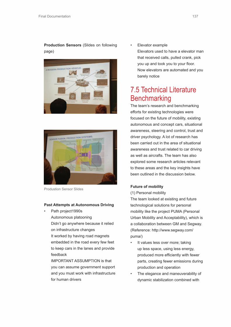
Final Documentation 137
Production Sensors (Slides on following page)
• Elevator example Elevators used to have a elevator man that received calls, pulled crank, pick you up and took you to your floor. Now elevators are automated and you barely notice
7.5 Technical Literature BenchmarkingThe team’s research and benchmarking efforts for existing technologies were focused on the future of mobility, existing autonomous and concept cars, situational awareness, steering and control, trust and driver psychology. A lot of research has been carried out in the area of situational awareness and trust related to car driving as well as aircrafts. The team has alsoexplored some research articles relevant to these areas and the key insights have been outlined in the discussion below.
Future of mobility(1) Personal mobility The team looked at existing and future technological solutions for personal mobility like the project PUMA (Personal Urban Mobility and Acceptability), which is a collaboration between GM and Segway. (Reference: http://www.segway.com/puma/)• It values less over more; taking
up less space, using less energy, produced more efficiently with fewer parts, creating fewer emissions during production and operation
• The elegance and maneuverability of dynamic stabilization combined with
Produstion Sensor Slides
Past Attempts at Autonomous Driving• Path project1990s
Autonomous platooning Didn’t go anywhere because it relied on infrastructure changes It worked by having road magnets embedded in the road every few feet to keep cars in the lanes and provide feedback IMPORTANT ASSUMPTION is that you can assume government support and you must work with infrastructure for human drivers

Final Documentation138
proven battery, sensing, and controls technologies come together to solve real transportation challenges
(2) Zipcar model versus Uber model for car sharing• These business models lead to the
concept of collaborative consumption. (Reference: http://www.collaborativeconsumption.com/the-movement/)
• Collaborative Consumption describes the rapid explosion in traditional sharing, bartering, lending, trading, renting, gifting, and swapping reinvented through network technologies on a scale and in ways never possible before.
• It would be a new era marked by - TRUST between strangers, ACCESS instead of ownership
Existing autonomous cars and driver assistance technologies
1. DARPA challenge Stanley is actuated via a drive-by-wire system developed by Volkswagen of America’s Electronic Research Lab. The vehicle incorporates measurements from GPS, a 6DOF inertial measurement unit, and wheel speed for pose estimation. While the vehicle is in motion, the environment is perceived through four laser range finders, a radar system, a stereo camera pair, and a monocular vision system.
2. Nissan Steer by Wire technology brings car design closer to autonomous:http://auto.dohax.com/nissans-steer-by-wire-system-brings-us-closer-to-autonomouscars/As the car encounters obstacles / another vehicle, a pedestrian — the car steers itself to safety and stops. This technology has already been developed. So it is safe to assume that cars of the future will have the built in emergency stop feature and we only need to consider transitions during normal driving situations or when it is safe.
Stanley (a mod. VW), winner of DARPAs Grand Challenge
Boss (a mod. GM), winner of DARPAs Grand Challenge

Final Documentation 139
(BMW is also working on a new technology that detects health condition and incapacitated drivers and stops the car safely pulls over to the side and calls for help).
(3) Chris Gerdes - TED Video on autonomous cars:http://www.youtube.com/watch?v=q1sk47FLAmg&feature=player_embeddedGerdes believes that the optimal autonomous car tech will not necessarily replace humans, but should instead act as our coach. He believes that the optimal car will combine technology with human intuition and reflexes.
Concept Cars1. PAT Autonomous Vehicle – [1] • We can see that the vehicle itself has
been restructured to be like a clear cabin with the walls themselves being interactive interfaces.
2. VW hover car– [2] The car shape is more like a pod and steering is a car shaped joystick. So the controller is more intuitive and the car responds exactly how the user moves around the controller.
TrustReference paper – [3] The effects of adverse condition warning system characteristics on driver performance: an investigation of alarm signal type and threshold levelDescription – The study addresses the issues concerning the design of adverse condition warning systems (ACWS), which warns the drivers about adverse road and weather conditions, or even system conditions that can lead to skids or accidents.Relevant ideas and conclusions:Results of the study indicate that drivers respond better to a low sensitivity and graded alarm signal condition compared to other alert configurations. Applied to this project, it means that if warnings or information is too sensitive and is displayed too often then users will not trust the system as much and even get irritated by it. A graded alarm system means that it goes from a low level alarm much before to a high level alarm when the event is near in time.
VW Hover Car

Final Documentation140
Situational Awareness:1. FORD SYNC (similar to Kia UVO (short for your voice) powered by Microsoft: [4]• SYNC lets you use your phone,
browse and choose music and find your way to just about anywhere - all while keeping your eyes on the road and hands on the wheel.
• Features: Calling, Entertainment, Navigation, Assist, Vehicle Health Report with just voice commands. Minimal interface and minimal buttons to distract you.
2. GMs OnStar 4G LTE dashboard: [6]• Future of automobile safety, security
and infotainment• Using your smartphone to monitor
your vehicle real time through a series of cameras mounted on the car
• Immediate notification of any impact/damage transmitted directly to your smartphone
• Video tutorials combined with text based info (everything on the touchscreen in the car) shows how to use the different controls (Like the past Audi project had nfo buttons)
• Voice command navigation. Navigation system that connects with traffic camera allowing you to see in real time the state of the traffic on the route
3. Reference paper [7] - An empirical
study of auditory warnings in aircraftRelevant ideas and conclusions:• Pilots prefer visual over auditory
warnings when there is enough time to react (Stokes et al. 1990). However if the visual channel is overloaded there are obvious advantages in allocating some tasks to other sensory channels.
• Advantages of auditory information: a) Can be received regardless of head position and orientation of the user b) Response time to an acoustic signal can be shorter than for a visual one (Kramer, 1994) c) Loud enough auditory warnings attract attention regardless of the task in which the user is engaged at the time d) The user might miss visual cues in high workload environments (Edworthy, 1994)
• Disadvantages of auditory information: a) If the signal is too loud and harsh that can lead to distraction b) If two alarms or signals go off at the same time that would be problematic to convey
• Gaver (1986) has proposed the use of auditory icons. They are caricatures of natural sounds that describe the essential feature of the event that they portray. For events that do not have natural sounds, earcons have been proposed which are essentially certain sounds, which the users learn to associate with the corresponding
Final Documentation 141
4. Reference Study [8] Collision Warning Design to Mitigate Driver DistractionThis study also found that the drivers trusted the graded warning system more. The interesting conclusion was that haptic warnings were preferred to auditory warnings on several dimensions including trust, overall benefit to driving and annoyance. These results suggest that non-standard warning modes like haptic cues from a vibrating seat or a vibrating control input need to be considered for information or warning system design.
7.6 Critical Function Prototype – Golf Cart7.6.1 Golf Cart CFP ResultsIn the incremental pedal data, once we give them steering control along with pedals they neglect pedals completely. The car speed drops down a lot, sometimes even close to a stop.• In the incremental pedal data, once
we give them steering control along with pedals they neglect pedals completely. The car speed drops down a lot, sometimes even close to a stop.
• In general comparing the incremental data versus the direct transfer data shows that the matching error for the entire transition sequence is much lower in the direct transition.
The graphs are shown on the next page. The black line represents the data from the users and the blue line represents the ideal data that they were expected to follow. Steering and pedal data graphs have been separated. In the graphs for the incremental transition, the three regionsbeing shown are completely autonomous mode, pedal matching mode and steering matchingmode. In the direct transition there are only two modes, autonomous and manual. It should be noted that the user is actually given complete control of the car in the direct transition; however the graph is showing the time in manual mode when the interface was visible to the user.
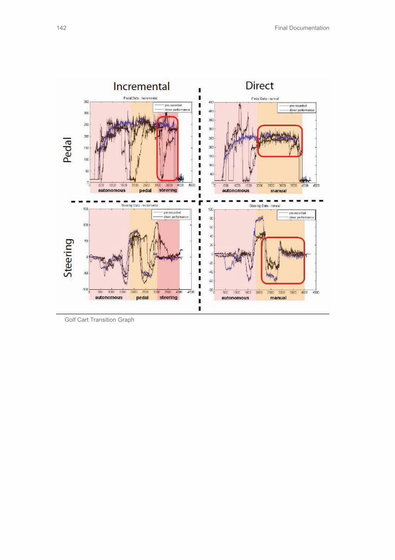
Final Documentation142
Golf Cart Transition Graph

Final Documentation 143
7.6.2 Golf Cart – C# Code for Gradual Controlusing System;using System.Collections.Generic;using System.ComponentModel;using System.Data;using System.Drawing;using System.Linq;using System.Text;using System.Windows.Forms;using System.IO.Ports;using System.IO;
// using the ADXL345 accelerometer - Sparkfun tutorial 240// incremental
namespace WindowsFormsApplication1{ public partial class Form1 : Form { public Form1() { InitializeComponent(); }
private void button1_Click(object sender, EventArgs e) { SerialPort serialPort1 = new SerialPort(); serialPort1.PortName = “COM10”; serialPort1.BaudRate = 9600;
serialPort1.Open();
System.Drawing.Pen myPen; myPen = new System.Drawing.Pen(System.Drawing.Color.Red); myPen.Width = 2;
System.Drawing.Pen myPen_auto; myPen_auto = new System.Drawing.Pen(System.Drawing.Color.Green); myPen_auto.Width = 2;

Final Documentation144
System.Drawing.SolidBrush myBrushGray = new System.Drawing.SolidBrush(System.Drawing.Color.LightGray); System.Drawing.SolidBrush myBrushYellow = new System.Drawing.SolidBrush(System.Drawing.Color.LightBlue);
System.Drawing.Graphics formGraphics = this.CreateGraphics();
if (serialPort1.IsOpen) textBox1.Text = “Done”; else textBox1.Text = “Not”;
textBox3.Font = new Font(“Georgia”, 16); textBox3.BackColor = Color.LightGreen; textBox3.BorderStyle = BorderStyle.FixedSingle; textBox3.TextAlign = HorizontalAlignment.Center; textBox3.Text = “Throttle matched”; textBox3.Visible = false; int trial_int = 0; string trial_msg = “0”; int flg = 0;
while(flg == 0) { trial_msg = serialPort1.ReadLine(); try { trial_int = Int32.Parse(trial_msg); } catch { } if (trial_int == 1234) break; }

Final Documentation 145
while (flg == 0) { trial_msg = serialPort1.ReadLine(); try { trial_int = Int32.Parse(trial_msg); } catch { } if (trial_int == 5678) { flg = 1; break; } }
int count = 0; int error_count = 0; int error = 0; int last_error = 0; int error_threshold = 150; int count_threshold = 200; //should be 200 bool pedalAchieved = false; int time_count = 0; int label_count = 0; progressBar1.Maximum = count_threshold;
int steering_error_count = 0; int steering_error = 0; int steering_last_error = 0; int steering_error_threshold = 50; int steering_count_threshold = 150; bool steeringAchieved = false; //int label_count = 0; progressBar2.Maximum = steering_count_threshold;

Final Documentation146
// dummy defines just to avoid definition errors FileStream fs = new FileStream(“Z:/Acads/Year2/ME310A/AUDI/CFP/Software/Csharp Trials/Scenario2/defaultfile.txt”,FileMode.Open,FileAccess.Read); StreamReader sr = new StreamReader(fs);
// dummy defines just to avoid definition errors FileStream fsw = new FileStream(“Z:/Acads/Year2/ME310A/AUDI/CFP/Software/Csharp Trials/Scenario2” + “defaultfile2.txt” , FileMode.Append, FileAccess.Write); StreamWriter sw = new StreamWriter(fsw);
int pot = 0; int pot2 = 0; int pot_auto = 0; int pot2_auto = 0; int button_flg = 0; int last_button_flg = -1; double angle_offset = Math.PI / 2; double angle_buffer_range = Math.PI / 5;
if (checkBox2.Checked) { fs = new FileStream(“Z:/Acads/Year2/ME310A/AUDI/CFP/Software/Csharp Trials/” + textBox2.Text, FileMode.Open, FileAccess.Read); sr = new StreamReader(fs);
fsw = new FileStream(“Z:/Acads/Year2/ME310A/AUDI/CFP/Software/Csharp Trials/Scenario2/” + “data” + textBox2.Text, FileMode.Append, FileAccess.Write); sw = new StreamWriter(fsw); } while (true) { //increment time counter if pedal not achieved if (button_flg == 1) { time_count++; }

Final Documentation 147
if (textBox3.Visible) { label_count++; if (label_count == 150) { textBox3.Visible = false; label_count = 0; } }
String msg0 = serialPort1.ReadLine(); String message = serialPort1.ReadLine(); String message2 = serialPort1.ReadLine();
button_flg = Int32.Parse(msg0); pot = Int32.Parse(message); pot2 = Int32.Parse(message2);
if (checkBox1.Checked) { fsw = new FileStream(“Z:/Acads/Year2/ME310A/AUDI/CFP/Software/Csharp Trials/Scenario2” + textBox2.Text, FileMode.Append, FileAccess.Write); sw = new StreamWriter(fsw); sw.WriteLine(message + “ “ + message2); sw.Flush(); sw.Close(); fsw.Close(); }
if (checkBox2.Checked) { //string[] lines = System.IO.File.ReadAllLines(@”Z:/Acads/Year2/ME310A/AUDI/CFP/Software/Csharp Trials/Scenario2trial1.txt”); //string lines_check = lines[2]; String str1 = sr.ReadLine(); String str2 = sr.ReadLine(); String str3 = sr.ReadLine();

Final Documentation148
pot_auto = Convert.ToInt32(str1); pot2_auto = Convert.ToInt32(str2);
sw.WriteLine(message + “ “ + message2); //sr.Close(); //fs.Close(); }
count++;; if (count == 4) { progressBar1.Value = error_count; progressBar2.Value = steering_error_count; //textBox1.Text = error_count.ToString(); formGraphics.Clear(Color.FromName(“Control”));
//int formHeight = 370; int formHeight = 250; //Current Graphics if (pedalAchieved) { pot2 = 100; pot2_auto = 100; }
int rectX1 = 0; int rectY1 = formHeight-pot2 / 3; int rectWidth = 400; int rectHeight = 200; int rectX1_auto = 0; int rectY1_auto = formHeight - pot2_auto / 3; int rectWidth_auto = 400; int rectHeight_auto = 200;
// Correct the graphics to have stationary auto throttle and display error rectY1 = rectY1 - rectY1_auto + 100; rectY1_auto = 100;
error = Math.Abs(pot2 - pot2_auto); steering_error = Math.Abs(pot - pot_auto);
// note down the switch

Final Documentation 149
if (checkBox2.Checked && last_button_flg == 0 && button_flg == 1) { sw.WriteLine(“**********Switch************************”); sw.WriteLine(time_count); sw.WriteLine(“**********************************”); } last_button_flg = button_flg;
////////////////////////////////////////// // Pedal matching code ///////////////////////////////////////// if (!pedalAchieved && error < error_threshold && last_error < error_threshold) { error_count++; } else if (!pedalAchieved && last_error < error_threshold && error >= error_threshold) { error_count = 0; } last_error = error;
if (!pedalAchieved && error_count == count_threshold) { // successfully matched throttle pedal int debug = 1; pedalAchieved = true; textBox3.Visible = true; label_count = 0;
if (checkBox2.Checked) { sw.WriteLine(“**********Pedal Matched************************”); sw.WriteLine(time_count); sw.WriteLine(“**********************************”); }

Final Documentation150
}
////////////////////////////////////////// // Steering matching code /////////////////////////////////////////
if (pedalAchieved && !steeringAchieved && steering_error < steering_error_threshold && steering_last_error < steering_error_threshold) { steering_error_count++; } else if (pedalAchieved && !steeringAchieved && steering_last_error < error_threshold && steering_error >= steering_error_threshold) { steering_error_count = 0; } steering_last_error = steering_error;
if (pedalAchieved && !steeringAchieved && steering_error_count == steering_count_threshold) { // successfully matched throttle pedal int debug = 1; steeringAchieved = true;
textBox3.Text = “Steering matched”; textBox3.Visible = true; label_count = 0;
if (checkBox2.Checked) { sw.WriteLine(“********Steering matched**********************”); sw.WriteLine(time_count); sw.WriteLine(“******************************”); } } float centerX = (rectX1 + rectWidth / 2);

Final Documentation 151
float centerY = (rectY1 + rectHeight / 2);
pot = pot * 2 / 3 + 30 * 22 / (7 * 180); double endPx = centerX + rectWidth * Math.Cos((pot) * Math.PI / (180) + angle_offset) / 2; double endPy = centerY - rectHeight * Math.Sin((pot) * Math.PI / (180) + angle_offset) / 2;
float centerX_auto = (rectX1_auto + rectWidth_auto / 2); float centerY_auto = (rectY1_auto + rectHeight_auto / 2);
pot_auto = pot_auto * 2 / 3 + 30 * 22 / (7 * 180); double endPx_auto = centerX + rectWidth_auto * Math.Cos((pot_auto) * Math.PI / (180) + angle_offset) / 2; double endPy_auto = centerY - rectHeight_auto * Math.Sin((pot_auto) * Math.PI / (180) + angle_offset) / 2;
// do not start matching in autonomous mode if (button_flg == 0) error_count = 0; //if (button_flg == 1) //{ //Autonomous Graphics if (checkBox2.Checked) {
if (pedalAchieved && !steeringAchieved) { // Steering related auto graphics float start_angle = (float)((((-pot_auto) * Math.PI / (180) - angle_offset - angle_buffer_range / 2) * 180 / Math.PI)); formGraphics.FillPie(myBrushYellow, (float)rectX1, (float)rectY1, (float)rectWidth, (float)rectHeight, start_angle, (float)(angle_buffer_range * 180 / Math.PI)); } else if(!pedalAchieved) { // Throttle related auto graphics formGraphics.FillRectangle(myBrushGray, new Rectangle(rectX1_auto,

Final Documentation152
rectY1_auto, rectWidth_auto, rectHeight_auto / 3)); formGraphics.DrawArc(myPen_auto, rectX1_auto, rectY1_auto, rectWidth_auto, rectHeight_auto, 210, 120); //formGraphics.DrawLine(myPen_auto, centerX, centerY, (float)endPx_auto, (float)endPy_auto); //(float)endPx, (float)endPy } // }
//Current Graphics if (!pedalAchieved) { // Throttle related current graphics formGraphics.DrawArc(myPen, rectX1, rectY1, rectWidth, rectHeight, 210, 120); } else if (pedalAchieved && !steeringAchieved) { // Steering related current graphics formGraphics.DrawLine(myPen, centerX, centerY, (float)endPx, (float)endPy); //(float)endPx, (float)endPy }
// reference for the passenger driver int shift = 100; int centerXnew = 400; int centerYnew = 200; double endPx_auto_new = centerXnew + rectWidth_auto * Math.Cos((pot_auto) * Math.PI / (180) + angle_offset) / 2; double endPy_auto_new = centerYnew - rectHeight_auto * Math.Sin((pot_auto) * Math.PI / (180) + angle_offset) / 2; double endPx_new = centerXnew + rectWidth * Math.Cos((pot) * Math.PI / (180) + angle_offset) / 2; double endPy_new = centerYnew - rectHeight * Math.Sin((pot) * Math.PI / (180) + angle_offset) / 2; formGraphics.DrawLine(myPen, centerXnew + shift, centerYnew + shift, (float)endPx_new + (float)shift, (float)endPy_new + (float)shift); formGraphics.DrawLine(myPen_auto, centerXnew + shift, centerYnew + shift, (float)endPx_auto_new + (float)shift, (float)endPy_auto_new + (float)shift); //(float)endPx, (float)endPy

Final Documentation 153
} count = 0; } }
myPen.Dispose(); formGraphics.Dispose(); }
private void textBox1_TextChanged(object sender, EventArgs e) {
}
private void progressBar1_Click(object sender, EventArgs e) {
}
private void button2_Click(object sender, EventArgs e) { this.Close(); }
private void numericUpDown1_ValueChanged(object sender, EventArgs e) {
} }}

Final Documentation154
7.7 Online Research
Link
/Titl
eD
escr
iptio
nC
omm
ents
Who
add
edht
tp://
ieee
xplo
re.ie
ee.o
rg/s
tam
p/st
amp.
jsp?
tp=&
arnu
mbe
r=59
4527
5A
uton
omou
s ve
hicl
e co
ntro
lled
with
iPad
San
gram
No
Link
CM
U a
lso
has/
had
a go
od a
uton
omou
sca
r pro
gram
a c
oupl
e of
yea
rs b
ack
San
gram
http
://w
ww
.aut
oevo
lutio
n.co
m/n
ews/
who
-nee
ds-p
arki
ng-
sens
ors-
with
-an-
invi
sibl
e-ba
ck-s
eat-5
0139
.htm
lTr
ansp
aren
t mat
eria
ls fo
r sea
ts e
gW
e m
ight
wan
t to
look
into
futu
re m
ater
ials
like
this
Tom
mi
http
://as
asi.o
rg/p
aper
s/20
04/S
happ
ell%
20et
%20
al_H
FAC
S_I
SA
SI0
4.pd
fH
uman
err
or, t
he m
ost c
omm
on c
ause
acci
dent
s w
ith c
ars.
Abo
ut 6
0-80
% in
cas
es a
cra
sh is
cau
sed
by a
hum
an e
rror
.To
mm
i
http
://au
to.h
owst
uffw
orks
.com
/car
-driv
ing-
safe
ty/a
ccid
ents
-ha
zard
ous-
cond
ition
s/tra
ffic.
htm
Sta
tistic
s w
hat k
inds
of h
arm
is c
ause
d by
traffi
cE
.g. w
aste
d tim
e an
d fu
el w
orth
abo
ut $
78 b
illio
n.To
mm
i
http
://w
ww
.nyt
imes
.co
m/2
011/
05/2
9/bu
sine
ss/e
cono
my/
29vi
ew.h
tml
Was
ted
time
Am
eric
ans
spen
d an
ave
rage
of 1
00 h
ours
sitt
ing
in tr
affic
eve
ry y
ear
Tom
mi
http
://en
.wik
iped
ia.o
rg/w
iki/A
ugm
ente
d_re
ality
AR
(Aug
men
ted
Rea
lity)
Inte
rest
ing
tech
onlo
gy w
here
com
pute
r add
s di
gita
l rea
lity
to e
xist
ing
real
ity. I
ntro
duce
d in
200
7. C
ould
may
be u
sed
on fu
ture
win
dshi
eld?
(20x
x?).
Tom
mi
http
://w
ww
.you
tube
.com
/wat
ch?v
=P9K
PJl
A5y
dsA
R (A
ugm
ente
d R
ealit
y)In
tere
stin
g vi
de o
f BM
W u
sing
AR
tech
nolo
gy to
ass
ist r
epai
ring
(200
7).
Tom
mi
http
://au
to.h
owst
uffw
orks
.com
/und
er-th
e-ho
od/tr
ends
-in
nova
tions
/5-fu
ture
-car
-tech
nolo
gies
3.ht
mA
R (A
ugm
ente
d R
ealit
y)A
rticl
e cl
aim
ing
this
wou
ld b
e in
futre
car
s (2
0xx?
).To
mm
i
http
://w
ww
.you
tube
.com
/wat
ch?
v=U
7Uro
LFY
lzE
&fe
atur
e=re
late
dFu
ture
Inte
llige
nce
Bas
ical
ly m
ost o
f the
stu
ff in
trodu
ced
befo
re g
athe
red
in o
ne in
tere
stin
gvi
deo.
Gor
an
http
://w
ww
.futu
retim
elin
e.ne
tFu
ture
pre
dict
ions
This
web
site
is n
ot 1
00%
relia
ble,
but
it p
rovi
des
som
e vi
sion
of t
hefu
ture
and
it h
as a
pol
l on
whe
ther
you
will
trus
t an
auto
nom
ous
vehi
cle
:).G
oran
http
://w
ww
.you
tube
.com
/wat
ch?v
=uqe
o_Zv
-G
xE&
feat
ure=
rela
ted
Wor
ld in
205
7D
isco
very
cha
nnel
vid
eoG
oran
http
://w
ww
.dai
lym
otio
n.co
m/v
ideo
/xcu
in0_
next
-wor
ld-fu
ture
-da
nger
-5th
-apr
il_sh
ortfi
lms?
sear
ch_a
lgo=
2Fu
ture
veh
icle
s to
day
Dis
cove
ry c
hann
el v
ideo
- pa
rt1 fr
om th
e se
ries
Gor
an
http
s://w
ww
.you
tube
.com
/wat
ch?
v=21
9Yyb
X66
MY
&fe
atur
e=re
late
dS
peec
h fro
m U
nive
rsity
pro
fess
or a
bout
the
futu
reLe
ctur
e ab
out f
utur
e of
tech
nolo
gy in
203
0G
oran
http
s://w
ww
.you
tube
.com
/wat
ch?
v=K
54LN
9q1j
Ss&
feat
ure=
rela
ted
Ano
ther
spe
ech
from
the
sam
e gu
yLe
ctur
e by
Mic
hio
Kak
uG
oran
http
://w
ww
.you
tube
.com
/wat
ch?
v=7i
c0JA
H8r
co&
feat
ure=
relm
fuB
eyon
d 20
00 s
how
Just
as
an e
xam
ple
of a
n ep
isod
e of
bey
ond
2000
.It w
as s
how
n 20
yea
rsag
o an
d w
e ca
n se
e ho
w m
uch
the
wor
ld d
evel
oped
for t
hat t
ime.
Gor
an
http
://au
to.h
owst
uffw
orks
.com
/car
-driv
ing-
safe
ty/a
ccid
ents
-ha
zard
ous-
cond
ition
s/tra
ffic.
htm
Traf
fic s
tatis
tics
From
Tom
mi's
link
. Don
't re
ad it
. It j
ust s
how
s ho
w m
uch
time
we
spen
din
t raf
fic. I
t will
be
usef
ull i
n do
cum
enta
tion
one
day.
Gor
an
http
s://w
ww
.you
tube
.com
/wat
ch?v
=reI
yTH
HC
d-c
Inte
llige
nce
revo
lutio
n
A d
ocum
enta
ry a
bout
virt
ual r
ealit
y, ro
bots
, AI..
. Int
eres
ting
- It r
aise
d a
ques
tion
that
we
can
bond
to a
mac
hine
if it
sho
ws
emot
ions
and
pers
onal
ity. M
aybe
our
car
can
be
emot
iona
l?! M
aybe
then
we
will
trus
t it
mor
e?!
Gor
an

Final Documentation 155
Link/Title Description Comments Who added
http://en.wikipedia.org/wiki/Motion_sickness Motion Sickness Some brife explanation what ismotion sickness Tommi
http://www.medicinenet.com/motion_sickness/article.htm Motion Sickness What causes motion sicknessetc Tommi
http://www.viban.com/motionsickness.htm Motion sicknessproduct A solution for motion sickness Steph
http://en.wikipedia.org/wiki/Tilting_train Tilting Train Active compensation Sangram
http://www.google.com/patents/US20040035347
2006 Patent -Autonomous, selfleveling, selfcorrecting anti-motion sicknesschair, bed
Active compensation -gyroscope based Sangram
http://www.google.com/patents/US7717841 Patent for motionsickness
Look at the references. Thereare many more differentsolutions for motion sicknessthat people have come up with.Maybe we can just list theinteresting ones here
Sangram
Link/Title Description Comments Who added
http://www.audi.co.uk/new-cars/a8/a8/safety/pre-sense.html Audi pre sense
Currently available system.Includes floowing systems:Audi adaptive cruise control,Audi lane assist, Audi SideAssist, Night vision, andAudi Adaptive Lights.
Tommi
http://www.audi.com/com/brand/en/tools/advice/glossary.html Audi adaptive cruise control Currently available system Tommi
http://www.audi.com/com/brand/en/tools/advice/glossary.html Audi Adaptive Air Suspension-sport Currently available system Tommi
http://www.audi.com/com/brand/en/tools/advice/glossary.html Audi Adaptive Lights Currently available system Tommi
http://www.audi.com/com/brand/en/tools/advice/glossary.html Auto-dimming Mirrors Currently available system Tommi
http://www.audi.com/com/brand/en/tools/advice/glossary.html Audi Side Assist Currently available system Tommi
http://www.audi.com/com/brand/en/tools/advice/glossary.html Audi Parking System Currently available system Tommi
http://www.audi.com/com/brand/en/tools/advice/glossary.html Audi lane assist Currently available system Tommi
http://www.audi.com/com/brand/en/tools/advice/glossary.html Night vision Currently available system Tommi
http://www.autoevolution.com/news/volvo-city-safety-lowers-insurance-rating-for-all-uk-bound-v40s-50033.html
AEB (Autonomous Emergency Breaking) Currently available systemintroduced by Volvo. Tommi
http://en.wikipedia.org/wiki/Electronic_stability_control
ESC (Electric Stability Control)ESP (Electric Stability Program)DSC (Dynamic Stability Control)
Introduced by BMW andMerced-Benz in 1987. Tommi
http://www.autoevolution.com/news/cadillac-virtual-bumper-helps-avoid-parking-crashes-49613.html
Parking sensors mixed with autonomous parking ifdriver is about to ht something while parking.
Currently available systemintroduced by Cadillac. Tommi
http://wot.motortrend.com/continental-wants-emergency-steer-assist-to-drive-cars-away-from-accidents-8013.html
ESA (Emergency Steering Assist)
In addition to breaking, thecar also knows how to steerin emergency situation.Introduced by continentaland it's available in nearfuture (2015?).
Tommi
http://green.autoblog.com/2008/08/20/continental-introduces-force-feedback-accelerator-pedal/ AFFP (Accelerator Force Feedback Pedal)
Already available.Introduced by Continental in2008.
Tommi
http://auto.howstuffworks.com/under-the-hood/trends-innovations/5-future-car-technologies4.htm
Air Bag
Technology studied byMercedes-Benz. Idea is tostop the car itself with airbags :D.
Tommi

Final Documentation156
Link/Title Description Comments Who added
https://cyberlaw.stanford.edu/files/publication/files/2012-Smith-
AutomatedVehiclesAreProbablyLegalinTheUS_0.pdf
White paper on legality of autonomouscars in the US
99 page document - extensive discussion about thelegality of autonomous cars (This however is not that
relevant now that robocars have been legalized inCalifornia)
Sangram
http://www.theatlanticcities.com/commute/2012/09/driverless-cars-would-reshape-automobiles-and-transit-
system/3432/
Article about autonomous carsreshaping the future
Important points from the article and user comments:transportation as a service model, dealership
package of owning a personal car + having free mileson the robo-service-car, reference to transit orientedenviromentalists/activists (we need to look at their
views and why they are against this), servicerobocars solve the parking space problems, robocarscan really blur the line between "public" and "private"transportation, concept of dynamic carpooling usingrobocars and smartphones, problems in robotaxis inhandling large crowds of people after the Big Gamelets say coming out of the stadium?, City planning -
model of "free-floating semi-autonomous peopletransporters" would only push us toward building
more disconnected places?, car owners renting outtheir robocars (other more advanced models to zipcar
and car-sharing)
Sangram
http://ideas.4brad.com/ Awesome blog about robocars Leads to more links, Still being updated regularly Sangramhttp://www.autoevolution.com/news/nissan-hops-aboard-self-driving-train-with-nsc-2015-video-50028.html
Autonomous parking introduced byNissan
Parking which can be controlled with a smartpohone.Avaivable in near future (2015). Tommi
Link/Title Description Comments Who added
http://conferences.ifpri.org/2020conference/PDF/summary_bongaarts.pdf
Study aboutpopultaion growth
Population of earth is likely toincrease with 3 billion between2001-2050. Relevance to our cabinis might not be that good :D.
Tommi
http://view.fdu.edu/files/humanvaluessustainability.pdf
Modern humanbeing's values
Good insight in current humanvalues. A lot of useless stuff butsome relevant stuff also. Articlepublished 2010.
Tommi
http://www.futuretimeline.net/21stcentury/2020.htm 2020 people profile
Completely new generation will rulethe world in future. People more likeyou and me. Less religious, moreliberal...
Goran
Final Documentation 157
7.8 Fall Presentations 3P/33/3P�
3�
� � � � � � � � � � � � � � � � � � �
� � � � � � � � � � � � � � � � � � � � � � � � � � � � � � � � � � � � � �
� � � � � � � � � � � � � � � � � � � � � � � � � � � � � � � � � � �
� � � � � � � � � � � � � � � � � � � � � � � � � � � � � � � � � � � � � � � � � � � � �
� � � � � � �
Sangram Patil Stephanie Tomasetta David Wang
Goran Bjelajac Sifo Luo
Heikki Sj� man Tommi Tuulenm� ki
� � � � � � � � � � � � � � � � � � � � � � � �
¥ User trust is established.
� � � � � � � � � � � �
¥ User trust is established.
¥ Emergency situations are responded to by the AV.
Stanford Presentation Slides

Final Documentation158
3P/33/3P�
P�
Assumptions
¥ User trust is established.
¥ Emergency situations are responded to by the AV.
¥ Vehicle-to-Vehicle and Vehicle-to-Infrastructure communication technology is implemented.
Transition Trust Cabin Control
The Design Space
Transition Trust Cabin Control
The Design Space
Transition Testing the transition sequence from autonomous to manual control
_______ Display
______________ Switch
Transition: Gradual
� ���� � ����
� ������ ���
���� ������ ��� ����� ��
����� ���� ���� �
Transition: Direct
���� +���� ������ ��� ���� ��� � ����
����� ���� ���� �
� ������ ���
Transition: Key Insights Transition: Key Insights
¥ Visual representation of interactive information is too intrusive and distracting during driving.
Transition: Key Insights
¥ Visual representation of interactive information is too intrusive and distracting during driving.
¥ Performance is not based on the number of tasks being performed, but the coherence between the sources of information.

Final Documentation 159
3P/33/3P�
a�
Transition: Key Insights
¥ Visual representation of interactive information is too intrusive and distracting during driving.
¥ Performance is not based on the number of tasks being performed, but the coherence between the sources of information.
¥ People did not feel like they were driving when prompted to mimic the AV controls.
Transition Trust Cabin Control
The Design Space Trust Reason for trusting autonomous systems Experience of riding in an autonomous vehicle
���������������������1� � ��������� ����������������� ���������������
�������������������������� �������������������������� ������������������������
Trust: Key Insights Trust: Key Insights
¥ If the user sees what the cars sees, then trust is built.
Trust: Key Insights
¥ If the user sees what the cars sees, then trust is built.
¥ Having anticipatory cues for out of the ordinary situations leads to reassurance that everything is working.
Transition Trust Cabin Control
The Design Space Cabin Space Explore experience of having a moving chair in the cabin space
Interactive Windshield __________________
Movable Chair __________
Cabin Activity Space _______________________
Working Relaxing Socializing Interacting with multimedia Driving
Cabin Space: Key Insights

Final Documentation160
3P/33/3P�
r �
Cabin Space: Key Insights
¥ It is desirable to have the flexibility of moving around in the cabin space.
Cabin Space: Key Insights
¥ It is desirable to have the flexibility of moving around in the cabin space.
¥ Attaching the control input to the moving chair allows for the input to be used for multiple activities, including driving.
Transition Trust Cabin Control
The Design Space
Control Mechanisms Explore possibility of a different control mechanism that is more fun and easier to transition
Joystick Controlled Steering
Mind Control to Levitate Ball (Mindflex Duel Game)
Control Mechanisms: Key Insights Control Mechanisms: Key Insights
¥ Most non-conventional steering inputs are less precise and have a steep learning curve.
Control Mechanisms: Key Insights
¥ Most non-conventional steering inputs are less precise and have a steep learning curve.
¥ For crash-proof manual driving in the future, the control input’s primary function is to maintain the fun of driving.
Design Requirements Design Requirements
Comfortable Transition
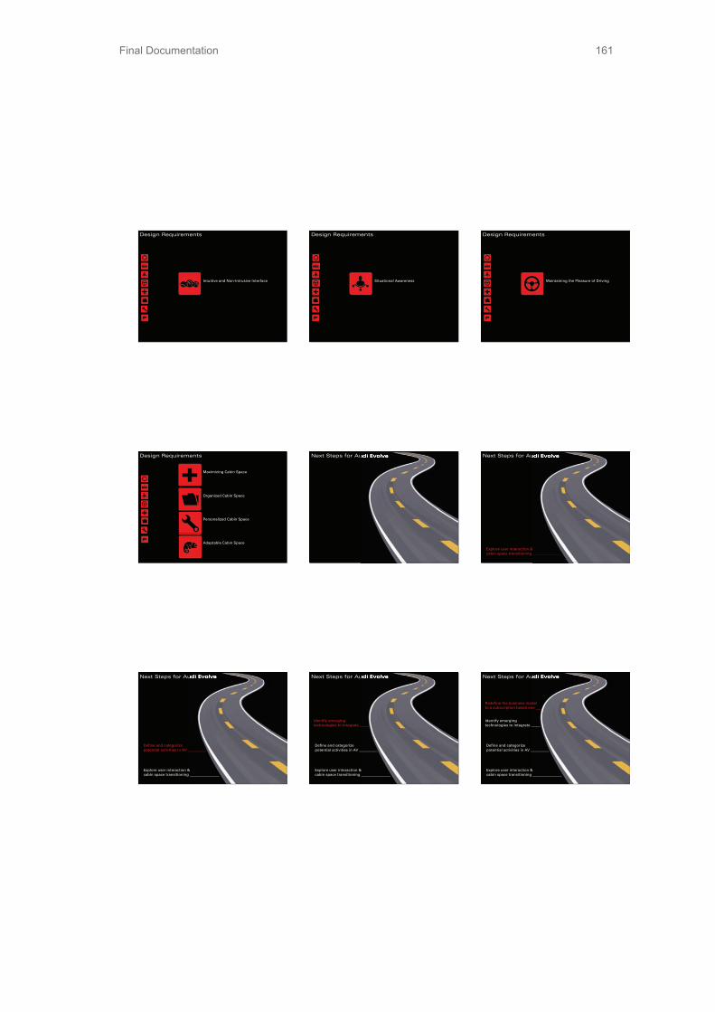
Final Documentation 161
3P/33/3P�
k�
Design Requirements
Intuitive and Non-Intrusive Interface
Design Requirements
Situational Awareness
Design Requirements
Maintaining the Pleasure of Driving
Design Requirements
Maximizing Cabin Space
Organized Cabin Space
Personalized Cabin Space
Adaptable Cabin Space
Next Steps for Audi Evolve Next Steps for Audi Evolve Next Steps for Audi Evolve Next Steps for Audi Evolve
Explore user interaction & cabin space transitioning ________________
Next Steps for Audi Evolve Next Steps for Audi Evolve
Define and categorize potential activities in AV __________
Explore user interaction & cabin space transitioning ________________
Next Steps for Audi Evolve Next Steps for Audi Evolve
Identify emerging technologies to integrate _____
Define and categorize potential activities in AV __________
Explore user interaction & cabin space transitioning ________________
Next Steps for Audi Evolve Next Steps for Audi Evolve
Redefine the business model to a subscription based one ___
Identify emerging technologies to integrate _____
Define and categorize potential activities in AV __________
Explore user interaction & cabin space transitioning ________________

Final Documentation1623P/33/3P�
i �
Next Steps for Audi Evolve Next Steps for Audi Evolve
Leverage the social impact of self-aware cars ____________________
Redefine the business model to a subscription based one ___
Identify emerging technologies to integrate _____
Define and categorize potential activities in AV __________
Explore user interaction & cabin space transitioning ________________
Questions?
Aalto Presentation Slides

Final Documentation 163
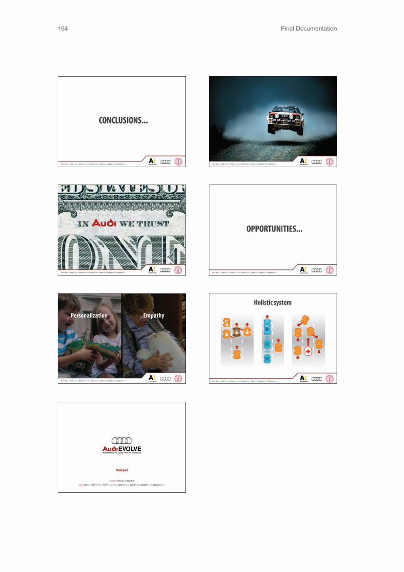
Final Documentation164

Final Documentation 165
7.9 Winter Presentation

Final Documentation166

Final Documentation 167

Final Documentation168
7.10 Winter Brochure
Possibilities to use the time and space in the autonomous car are only limited by the size of the car and people’s imagination. We found that the most common activities people wished to do in the car are working, relaxing, and socializing. Every one of those activities requires different body position and slightly different interior arrangement. The space in the car is very limited and there is just not enough space to move freely. How to create a comfortable and entertaining cabin envi-ronment is one of our tasks.
In order to ensure the quality and sophistica-tion Audi brand presents, we need to make driver experience during entire ride equally interesting. That includes both the experi-ence during activities in the car and the tran-sition between them as well.
The transition between autonomous and manual modes is another problem. If we look at only the transition from driving to autono-mous, we can immediately see that it is not easy at all. Letting go the control of your life
to a machine requires much more than just letting the steering wheel go. Drivers need a simplified sequence of mode changing not only to shorten their learning curve but also to have a feeling of safety.
Vision
We envision cars in the year 2035 as mov-ing personal space. Cars will be autonomous and it will have two driving modes - manual and autonomous. Drivers will no longer waste time because of the time spent on the road, but because of the possibility to use the time while traveling for something else than driv-ing. Those activities are going to be mainly working, relaxing, and socializing. The de-sign of the cabin will accommodate these ac-tivities as best as the size of the car allows to. This requires us to radically restructure the interior of the car. There might be only one seat in front, and this driver seat will have to be “smart” in a way that it senses what driver wants and thus eases the transition between activities and modes. Visual and audio guid-ance will also aid the transition by giving enough information to the driver.
EVOLVE

Final Documentation 169
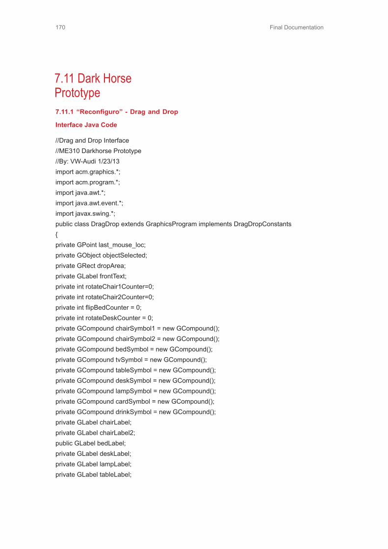
Final Documentation170
7.11 Dark Horse Prototype7.11.1 “Reconfiguro” - Drag and Drop
Interface Java Code
//Drag and Drop Interface//ME310 Darkhorse Prototype//By: VW-Audi 1/23/13import acm.graphics.*;import acm.program.*;import java.awt.*;import java.awt.event.*;import javax.swing.*;public class DragDrop extends GraphicsProgram implements DragDropConstants{private GPoint last_mouse_loc;private GObject objectSelected;private GRect dropArea;private GLabel frontText;private int rotateChair1Counter=0;private int rotateChair2Counter=0;private int flipBedCounter = 0;private int rotateDeskCounter = 0;private GCompound chairSymbol1 = new GCompound();private GCompound chairSymbol2 = new GCompound();private GCompound bedSymbol = new GCompound();private GCompound tvSymbol = new GCompound();private GCompound tableSymbol = new GCompound();private GCompound deskSymbol = new GCompound();private GCompound lampSymbol = new GCompound();private GCompound cardSymbol = new GCompound();private GCompound drinkSymbol = new GCompound();private GLabel chairLabel;private GLabel chairLabel2;public GLabel bedLabel;private GLabel deskLabel;private GLabel lampLabel;private GLabel tableLabel;

Final Documentation 171
private GLabel tvLabel;private GLabel cardLabel;private GLabel drinkLabel;private GCompound legend = new GCompound();public void init(){JButton resetAllButton = new JButton(“Reset All”);JButton resetSelectedButton = new JButton(“Reset Selected”);JButton rotateButton = new JButton(“Rotate Selected”);add(resetAllButton, NORTH);add(resetSelectedButton, NORTH);add(rotateButton, NORTH);setupDropArea();createObjects();createLegend();addActionListeners();addMouseListeners();}public void run(){}public void setupDropArea(){dropArea = new GRect(DROP_AREA_WIDTH, DROP_AREA_HEIGHT);dropArea.setLocation(DROP_AREA_CENTER_X, DROP_AREA_CENTER_Y);add(dropArea);frontText = new GLabel(“BACK OF VAN FRONT OF VAN”);frontText.setFont(“SansSerif-16”);add(frontText, DROP_AREA_CENTER_X + (DROP_AREA_WIDTH - frontText.getWidth())/2,DROP_AREA_CENTER_Y + DROP_AREA_HEIGHT + frontText.getHeight());}public void createObjects(){createBedSymbol(bedSymbol, BED_INIT_LOC_X, BED_INIT_LOC_Y);createChairSymbol(chairSymbol1, CHAIR1_INIT_LOC_X, CHAIR1_INIT_LOC_Y);createChairSymbol(chairSymbol2, CHAIR2_INIT_LOC_X, CHAIR2_INIT_LOC_Y);createTVSymbol(tvSymbol, TV_INIT_LOC_X, TV_INIT_LOC_Y);createTableSymbol(tableSymbol, TABLE_INIT_LOC_X, TABLE_INIT_LOC_Y);createDeskSymbol(deskSymbol, DESK_INIT_LOC_X, DESK_INIT_LOC_Y);

Final Documentation172
createLampSymbol(lampSymbol, LAMP_INIT_LOC_X, LAMP_INIT_LOC_Y);createDeckCardsSymbol(cardSymbol, DECK_CARDS_INIT_LOC_X, DECK_CARDS_INIT_LOC_Y);createDrinkSymbol(drinkSymbol, DRINK_INIT_LOC_X, DRINK_INIT_LOC_Y);}public void createLegend(){createLegendLabel();}public void createLegendLabel(){chairLabel = new GLabel(“CHAIR SELECTED”);chairLabel2 = new GLabel(“CHAIR SELECTED”);bedLabel = new GLabel(“BED SELECTED”);tvLabel = new GLabel(“TV PROJECTOR SELECTED”);tableLabel = new GLabel(“LOW TABLE SELECTED”);deskLabel = new GLabel(“DESK SELECTED”);lampLabel = new GLabel(“LAMP SELECTED”);cardLabel = new GLabel(“DECK OF CARDS SELECTED”);drinkLabel = new GLabel(“DRINK SELECTED”);add(chairLabel);add(chairLabel2);add(bedLabel);add(tvLabel);add(tableLabel);add(deskLabel);add(lampLabel);add(cardLabel);add(drinkLabel);chairLabel.setFont(“SansSerif-20”);chairLabel2.setFont(“SansSerif-20”);bedLabel.setFont(“SansSerif-20”);tvLabel.setFont(“SansSerif-20”);tableLabel.setFont(“SansSerif-20”);deskLabel.setFont(“SansSerif-20”);lampLabel.setFont(“SansSerif-20”);cardLabel.setFont(“SansSerif-20”);drinkLabel.setFont(“SansSerif-20”);}

Final Documentation 173
public void createChairSymbol(GCompound chair, int xPosition, int yPosition){GRect chair1 = new GRect(CHAIR_WIDTH, CHAIR_HEIGHT);GLine line1 = new GLine(CHAIR_MARGIN, CHAIR_MARGIN, CHAIR_WIDTH - CHAIR_MARGIN,CHAIR_MARGIN); //center horiz lineGLine line2 = new GLine(CHAIR_MARGIN, CHAIR_MARGIN, CHAIR_MARGIN, CHAIR_HEIGHT -CHAIR_MARGIN); //left vert lineGLine line3 = new GLine(CHAIR_WIDTH - CHAIR_MARGIN, CHAIR_HEIGHT - CHAIR_MARGIN, CHAIR_WIDTH- CHAIR_MARGIN, CHAIR_MARGIN); //right vert linechair.add(chair1);chair.add(line1);chair.add(line2);chair.add(line3);add(chair,xPosition, yPosition);}public void rotateChair(){int nextPosition = 0;GLine line1 = null, line2=null, line3=null, line4=null, line5=null, line6=null;GPoint objectLoc = objectSelected.getLocation();double x = objectLoc.getX();double y = objectLoc.getY();GRect chair1 = new GRect(CHAIR_WIDTH, CHAIR_HEIGHT);//Need to check which rotated position it is inif(objectSelected == chairSymbol1){nextPosition = rotateChair1Counter;}else if(objectSelected == chairSymbol2){nextPosition = rotateChair2Counter;}switch(nextPosition){case 0:

Final Documentation174
//****DOWN FACING CHAIR****/line1 = new GLine(CHAIR_MARGIN, CHAIR_MARGIN, CHAIR_WIDTH - CHAIR_MARGIN,CHAIR_MARGIN); //upper horiz lineline2 = new GLine(CHAIR_MARGIN, CHAIR_MARGIN, CHAIR_MARGIN, CHAIR_HEIGHT -CHAIR_MARGIN); //left vert lineline3 = new GLine(CHAIR_WIDTH - CHAIR_MARGIN, CHAIR_HEIGHT - CHAIR_MARGIN,CHAIR_WIDTH - CHAIR_MARGIN, CHAIR_MARGIN); //right vert lineline4 = new GLine(CHAIR_MARGIN, CHAIR_MARGIN, CHAIR_WIDTH - CHAIR_MARGIN,CHAIR_MARGIN); //upper horiz lineline5 = new GLine(CHAIR_MARGIN, CHAIR_MARGIN, CHAIR_MARGIN, CHAIR_HEIGHT -CHAIR_MARGIN); //left vert lineline6 = new GLine(CHAIR_WIDTH - CHAIR_MARGIN, CHAIR_HEIGHT - CHAIR_MARGIN,CHAIR_WIDTH - CHAIR_MARGIN, CHAIR_MARGIN); //right vert linebreak;case 1://****LEFT FACING CHAIR****///x1,y1 = upper_left point, x2,y2 = upper_right pointline1 = new GLine(CHAIR_MARGIN, CHAIR_MARGIN, CHAIR_WIDTH - CHAIR_MARGIN,CHAIR_MARGIN); //upper horiz line//x1,y1 = upper_right point, x2,y2 = bottom_left pointline2 = new GLine(CHAIR_WIDTH - CHAIR_MARGIN, CHAIR_HEIGHT - CHAIR_MARGIN,CHAIR_WIDTH - CHAIR_MARGIN, CHAIR_MARGIN); //right vert line//x1,y2 = bottom_left point, x2,y2 = bottom_right pointline3 = new GLine(CHAIR_MARGIN, CHAIR_HEIGHT - CHAIR_MARGIN, CHAIR_WIDTH -
CHAIR_MARGIN, CHAIR_HEIGHT - CHAIR_MARGIN); //bottom horiz line/*********///x1,y1 = upper_left point, x2,y2 = upper_right pointline4 = new GLine(CHAIR_MARGIN, CHAIR_MARGIN, CHAIR_WIDTH - CHAIR_MARGIN,CHAIR_MARGIN); //upper horiz line//x1,y1 = upper_right point, x2,y2 = bottom_left pointline5 = new GLine(CHAIR_WIDTH - CHAIR_MARGIN, CHAIR_HEIGHT - CHAIR_MARGIN,CHAIR_WIDTH - CHAIR_MARGIN, CHAIR_MARGIN); //right vert line//x1,y2 = bottom_left point, x2,y2 = bottom_right pointline6 = new GLine(CHAIR_MARGIN, CHAIR_HEIGHT - CHAIR_MARGIN, CHAIR_WIDTH -CHAIR_MARGIN, CHAIR_HEIGHT - CHAIR_MARGIN); //bottom horiz linebreak;case 2://****UP FACING CHAIR****/

Final Documentation 175
//x1,y1 = upper_right point, x2,y2 = bottom_left pointline1 = new GLine(CHAIR_WIDTH - CHAIR_MARGIN, CHAIR_HEIGHT - CHAIR_MARGIN,CHAIR_WIDTH - CHAIR_MARGIN, CHAIR_MARGIN); //right vert line//x1,y1 = upper_left point, x2,y2 = bottom_left pointline2 = new GLine(CHAIR_MARGIN, CHAIR_MARGIN, CHAIR_MARGIN, CHAIR_HEIGHT -CHAIR_MARGIN); //left vert line//x1,y2 = bottom_left point, x2,y2 = bottom_right pointline3 = new GLine(CHAIR_MARGIN, CHAIR_HEIGHT - CHAIR_MARGIN, CHAIR_WIDTH -CHAIR_MARGIN, CHAIR_HEIGHT - CHAIR_MARGIN); //bottom horiz line/******///x1,y1 = upper_right point, x2,y2 = bottom_left pointline4 = new GLine(CHAIR_WIDTH - CHAIR_MARGIN, CHAIR_HEIGHT - CHAIR_MARGIN,CHAIR_WIDTH - CHAIR_MARGIN, CHAIR_MARGIN); //right vert line//x1,y1 = upper_left point, x2,y2 = bottom_left pointline5 = new GLine(CHAIR_MARGIN, CHAIR_MARGIN, CHAIR_MARGIN, CHAIR_HEIGHT -CHAIR_MARGIN); //left vert line//x1,y2 = bottom_left point, x2,y2 = bottom_right pointline6 = new GLine(CHAIR_MARGIN, CHAIR_HEIGHT - CHAIR_MARGIN, CHAIR_WIDTH -CHAIR_MARGIN, CHAIR_HEIGHT - CHAIR_MARGIN); //bottom horiz linebreak;case 3://*****RIGHT FACING CHAIR*****///x1,y1 = upper_left point, x2,y2 = upper_right pointline1 = new GLine(CHAIR_MARGIN, CHAIR_MARGIN, CHAIR_WIDTH - CHAIR_MARGIN,CHAIR_MARGIN); //upper horiz line//x1,y1 = upper_left point, x2,y2 = bottom_left pointline2 = new GLine(CHAIR_MARGIN, CHAIR_MARGIN, CHAIR_MARGIN, CHAIR_HEIGHT -CHAIR_MARGIN); //left vert line//x1,y2 = bottom_left point, x2,y2 = bottom_right pointline3 = new GLine(CHAIR_MARGIN, CHAIR_HEIGHT - CHAIR_MARGIN, CHAIR_WIDTH -CHAIR_MARGIN, CHAIR_HEIGHT - CHAIR_MARGIN); //bottom horiz line/*******///x1,y1 = upper_left point, x2,y2 = upper_right pointline4 = new GLine(CHAIR_MARGIN, CHAIR_MARGIN, CHAIR_WIDTH - CHAIR_MARGIN,CHAIR_MARGIN); //upper horiz line//x1,y1 = upper_left point, x2,y2 = bottom_left point

Final Documentation176
line5 = new GLine(CHAIR_MARGIN, CHAIR_MARGIN, CHAIR_MARGIN, CHAIR_HEIGHT -CHAIR_MARGIN); //left vert line//x1,y2 = bottom_left point, x2,y2 = bottom_right pointline6 = new GLine(CHAIR_MARGIN, CHAIR_HEIGHT - CHAIR_MARGIN, CHAIR_WIDTH -CHAIR_MARGIN, CHAIR_HEIGHT - CHAIR_MARGIN); //bottom horiz line
break;default:break;}if(objectSelected == chairSymbol1){remove(chairSymbol1);chairSymbol1.removeAll();chairSymbol1.add(chair1);chairSymbol1.add(line1);chairSymbol1.add(line2);chairSymbol1.add(line3);add(chairSymbol1, x, y);}else if(objectSelected == chairSymbol2){remove(chairSymbol2);chairSymbol2.removeAll();chairSymbol2.add(chair1);chairSymbol2.add(line4);chairSymbol2.add(line5);chairSymbol2.add(line6);add(chairSymbol2, x, y);}}public void createBedSymbol(GCompound bed, int xPosition, int yPosition){GRect bed1 = new GRect(BED_WIDTH, BED_HEIGHT);GRect pillow = new GRect(BED_WIDTH/8, BED_HEIGHT*3/4);pillow.move(BED_WIDTH/10, pillow.getHeight()/5);GLine sheet = new GLine(30, 0,30,BED_HEIGHT);pillow.setFilled(true);bed.add(bed1);

Final Documentation 177
bed.add(pillow);bed.add(sheet);add(bed, xPosition, yPosition);}public void flipBed(){int nextPosition = 0;GRect bed = null, pillow = null;GLine sheet = null;GPoint objectLoc = objectSelected.getLocation();double x = objectLoc.getX();double y = objectLoc.getY();//Need to check which rotated position it is inif(objectSelected == bedSymbol){nextPosition = flipBedCounter;switch(nextPosition){case 0:
bed = new GRect(BED_WIDTH, BED_HEIGHT);pillow = new GRect(BED_WIDTH/8, BED_HEIGHT*3/4);pillow.move(BED_WIDTH/10, pillow.getHeight()/5);sheet = new GLine(30, 0,30,BED_HEIGHT);pillow.setFilled(true);break;case 1:bed = new GRect(BED_WIDTH, BED_HEIGHT);pillow = new GRect(BED_WIDTH/8, BED_HEIGHT*3/4);pillow.move(BED_WIDTH - BED_WIDTH/10 - pillow.getWidth(), pillow.getHeight()/5);sheet = new GLine(BED_WIDTH - 30, 0, BED_WIDTH - 30,BED_HEIGHT);pillow.setFilled(true);break;default:break;}remove(bedSymbol);bedSymbol.removeAll();bedSymbol.add(bed);
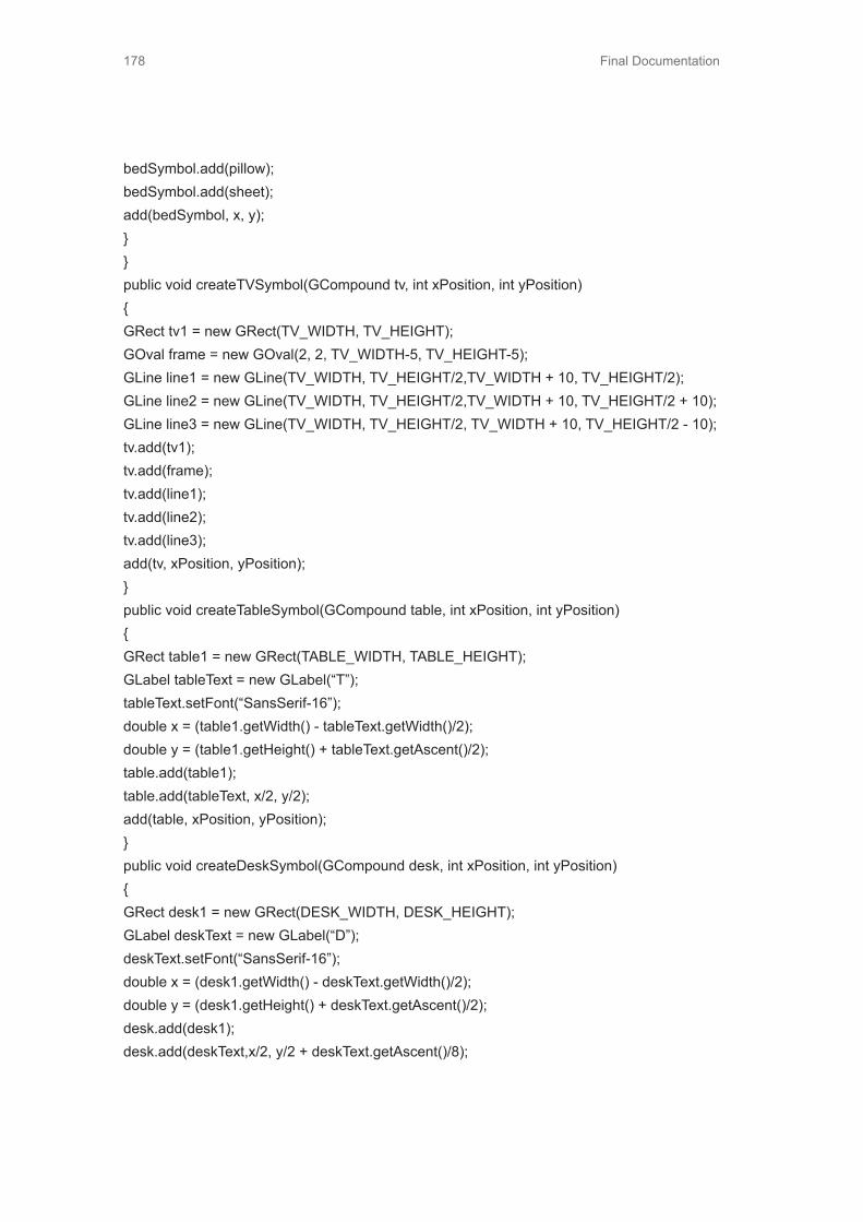
Final Documentation178
bedSymbol.add(pillow);bedSymbol.add(sheet);add(bedSymbol, x, y);}}public void createTVSymbol(GCompound tv, int xPosition, int yPosition){GRect tv1 = new GRect(TV_WIDTH, TV_HEIGHT);GOval frame = new GOval(2, 2, TV_WIDTH-5, TV_HEIGHT-5);GLine line1 = new GLine(TV_WIDTH, TV_HEIGHT/2,TV_WIDTH + 10, TV_HEIGHT/2);GLine line2 = new GLine(TV_WIDTH, TV_HEIGHT/2,TV_WIDTH + 10, TV_HEIGHT/2 + 10);GLine line3 = new GLine(TV_WIDTH, TV_HEIGHT/2, TV_WIDTH + 10, TV_HEIGHT/2 - 10);tv.add(tv1);tv.add(frame);tv.add(line1);tv.add(line2);tv.add(line3);add(tv, xPosition, yPosition);}public void createTableSymbol(GCompound table, int xPosition, int yPosition){GRect table1 = new GRect(TABLE_WIDTH, TABLE_HEIGHT);GLabel tableText = new GLabel(“T”);tableText.setFont(“SansSerif-16”);double x = (table1.getWidth() - tableText.getWidth()/2);double y = (table1.getHeight() + tableText.getAscent()/2);table.add(table1);table.add(tableText, x/2, y/2);add(table, xPosition, yPosition);}public void createDeskSymbol(GCompound desk, int xPosition, int yPosition){GRect desk1 = new GRect(DESK_WIDTH, DESK_HEIGHT);GLabel deskText = new GLabel(“D”);deskText.setFont(“SansSerif-16”);double x = (desk1.getWidth() - deskText.getWidth()/2);double y = (desk1.getHeight() + deskText.getAscent()/2);desk.add(desk1);desk.add(deskText,x/2, y/2 + deskText.getAscent()/8);
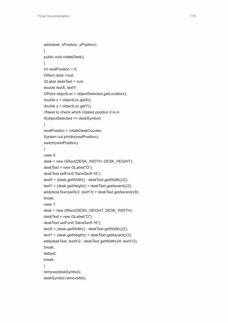
Final Documentation 179
add(desk, xPosition, yPosition);}public void rotateDesk(){int nextPosition = 0;GRect desk =null;GLabel deskText = null;double textX, textY;GPoint objectLoc = objectSelected.getLocation();double x = objectLoc.getX();double y = objectLoc.getY();//Need to check which rotated position it is inif(objectSelected == deskSymbol){nextPosition = rotateDeskCounter;System.out.println(nextPosition);switch(nextPosition){case 0:desk = new GRect(DESK_WIDTH, DESK_HEIGHT);deskText = new GLabel(“D”);deskText.setFont(“SansSerif-16”);textX = (desk.getWidth() - deskText.getWidth()/2);textY = (desk.getHeight() + deskText.getAscent()/2);add(deskText,textX/2, textY/2 + deskText.getAscent()/8);break;case 1:desk = new GRect(DESK_HEIGHT, DESK_WIDTH);deskText = new GLabel(“D”);deskText.setFont(“SansSerif-16”);textX = (desk.getWidth() - deskText.getWidth()/2);textY = (desk.getHeight() + deskText.getAscent()/2);add(deskText, textX/2 - deskText.getWidth()/4, textY/2);break;default:break;}remove(deskSymbol);deskSymbol.removeAll();
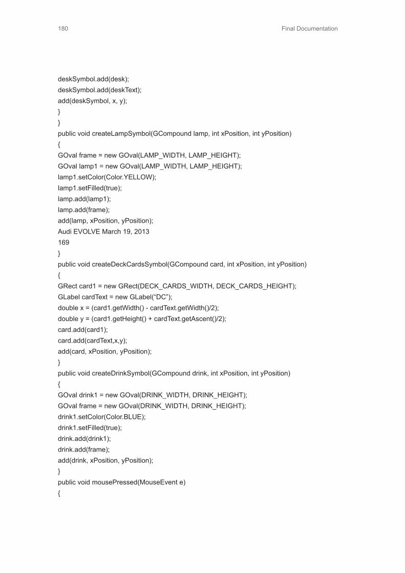
Final Documentation180
deskSymbol.add(desk);deskSymbol.add(deskText);add(deskSymbol, x, y);}}public void createLampSymbol(GCompound lamp, int xPosition, int yPosition){GOval frame = new GOval(LAMP_WIDTH, LAMP_HEIGHT);GOval lamp1 = new GOval(LAMP_WIDTH, LAMP_HEIGHT);lamp1.setColor(Color.YELLOW);lamp1.setFilled(true);lamp.add(lamp1);lamp.add(frame);add(lamp, xPosition, yPosition);Audi EVOLVE March 19, 2013169}public void createDeckCardsSymbol(GCompound card, int xPosition, int yPosition){GRect card1 = new GRect(DECK_CARDS_WIDTH, DECK_CARDS_HEIGHT);GLabel cardText = new GLabel(“DC”);double x = (card1.getWidth() - cardText.getWidth()/2);double y = (card1.getHeight() + cardText.getAscent()/2);card.add(card1);card.add(cardText,x,y);add(card, xPosition, yPosition);}public void createDrinkSymbol(GCompound drink, int xPosition, int yPosition){GOval drink1 = new GOval(DRINK_WIDTH, DRINK_HEIGHT);GOval frame = new GOval(DRINK_WIDTH, DRINK_HEIGHT);drink1.setColor(Color.BLUE);drink1.setFilled(true);drink.add(drink1);drink.add(frame);add(drink, xPosition, yPosition);}public void mousePressed(MouseEvent e){

Final Documentation 181
last_mouse_loc = new GPoint(e.getPoint());objectSelected = getElementAt(last_mouse_loc);if(objectSelected != null){if((objectSelected != dropArea) && (objectSelected != frontText)){objectSelected.sendToFront();if(objectSelected == bedSymbol){bedLabel.setVisible(true);bedLabel.setLocation(TEXT_ALIGN_X - bedLabel.getWidth()/2, TEXT_ALIGN_Y -bedLabel.getAscent()/2);}elsebedLabel.setVisible(false);if(objectSelected == chairSymbol1){chairLabel.setVisible(true);chairLabel.setLocation(TEXT_ALIGN_X - chairLabel.getWidth()/2, TEXT_ALIGN_Y -chairLabel.getAscent()/2);}elsechairLabel.setVisible(false);if(objectSelected == chairSymbol2){chairLabel2.setVisible(true);chairLabel2.setLocation(TEXT_ALIGN_X - chairLabel2.getWidth()/2, TEXT_ALIGN_Y- chairLabel2.getAscent()/2);}elsechairLabel2.setVisible(false);if(objectSelected == tvSymbol){tvLabel.setVisible(true);tvLabel.setLocation(TEXT_ALIGN_X - tvLabel.getWidth()/2, TEXT_ALIGN_Y -tvLabel.getAscent()/2);Audi EVOLVE March 19, 2013170}

Final Documentation182
elsetvLabel.setVisible(false);if(objectSelected == tableSymbol){tableLabel.setVisible(true);tableLabel.setLocation(TEXT_ALIGN_X - tableLabel.getWidth()/2, TEXT_ALIGN_Y -tableLabel.getAscent()/2);}elsetableLabel.setVisible(false);if(objectSelected == deskSymbol){deskLabel.setVisible(true);deskLabel.setLocation(TEXT_ALIGN_X - deskLabel.getWidth()/2, TEXT_ALIGN_Y -deskLabel.getAscent()/2);}elsedeskLabel.setVisible(false);if(objectSelected == lampSymbol){lampLabel.setVisible(true);lampLabel.setLocation(TEXT_ALIGN_X - lampLabel.getWidth()/2, TEXT_ALIGN_Y -lampLabel.getAscent()/2);}elselampLabel.setVisible(false);if(objectSelected == cardSymbol){cardLabel.setVisible(true);cardLabel.setLocation(TEXT_ALIGN_X - cardLabel.getWidth()/2, TEXT_ALIGN_Y -cardLabel.getAscent()/2);}elsecardLabel.setVisible(false);if(objectSelected == drinkSymbol){drinkLabel.setVisible(true);drinkLabel.setLocation(TEXT_ALIGN_X - drinkLabel.getWidth()/2, TEXT_ALIGN_Y -drinkLabel.getAscent()/2);

Final Documentation 183
}elsedrinkLabel.setVisible(false);}}else{bedLabel.setVisible(false);chairLabel.setVisible(false);chairLabel2.setVisible(false);tvLabel.setVisible(false);tableLabel.setVisible(false);deskLabel.setVisible(false);lampLabel.setVisible(false);cardLabel.setVisible(false);drinkLabel.setVisible(false);}}public void mouseDragged(MouseEvent e){if(objectSelected != null){//Need to check whether if the object is the drop area, if so don’t do anything and sent to backif((objectSelected != dropArea) && (objectSelected != frontText)){objectSelected.move(e.getX() - last_mouse_loc.getX(), e.getY() - last_mouse_loc.getY());last_mouse_loc = new GPoint(e.getPoint());if((objectSelected != dropArea) && (objectSelected != frontText)){objectSelected.sendToFront();if(objectSelected == bedSymbol){bedLabel.setVisible(true);bedLabel.setLocation(TEXT_ALIGN_X - bedLabel.getWidth()/2,TEXT_ALIGN_Y - bedLabel.getAscent()/2);}elsebedLabel.setVisible(false);

Final Documentation184
if(objectSelected == chairSymbol1){chairLabel.setVisible(true);chairLabel.setLocation(TEXT_ALIGN_X - chairLabel.getWidth()/2,TEXT_ALIGN_Y - chairLabel.getAscent()/2);}elsechairLabel.setVisible(false);if(objectSelected == chairSymbol2){chairLabel2.setVisible(true);chairLabel2.setLocation(TEXT_ALIGN_X -chairLabel2.getWidth()/2, TEXT_ALIGN_Y - chairLabel2.getAscent()/2);}elsechairLabel2.setVisible(false);if(objectSelected == tvSymbol){tvLabel.setVisible(true);tvLabel.setLocation(TEXT_ALIGN_X - tvLabel.getWidth()/2,TEXT_ALIGN_Y - tvLabel.getAscent()/2);}elsetvLabel.setVisible(false);if(objectSelected == tableSymbol){tableLabel.setVisible(true);tableLabel.setLocation(TEXT_ALIGN_X - tableLabel.getWidth()/2,TEXT_ALIGN_Y - tableLabel.getAscent()/2);}elsetableLabel.setVisible(false);if(objectSelected == deskSymbol){deskLabel.setVisible(true);deskLabel.setLocation(TEXT_ALIGN_X - deskLabel.getWidth()/2,TEXT_ALIGN_Y - deskLabel.getAscent()/2);}else

Final Documentation 185
deskLabel.setVisible(false);if(objectSelected == lampSymbol){lampLabel.setVisible(true);lampLabel.setLocation(TEXT_ALIGN_X - lampLabel.getWidth()/2,TEXT_ALIGN_Y - lampLabel.getAscent()/2);}elselampLabel.setVisible(false);if(objectSelected == cardSymbol){cardLabel.setVisible(true);cardLabel.setLocation(TEXT_ALIGN_X - cardLabel.getWidth()/2,TEXT_ALIGN_Y - cardLabel.getAscent()/2);}elsecardLabel.setVisible(false);if(objectSelected == drinkSymbol){drinkLabel.setVisible(true);drinkLabel.setLocation(TEXT_ALIGN_X - drinkLabel.getWidth()/2,TEXT_ALIGN_Y - drinkLabel.getAscent()/2);}elsedrinkLabel.setVisible(false);}else{bedLabel.setVisible(false);chairLabel.setVisible(false);chairLabel2.setVisible(false);tvLabel.setVisible(false);tableLabel.setVisible(false);deskLabel.setVisible(false);lampLabel.setVisible(false);cardLabel.setVisible(false);drinkLabel.setVisible(false);}}

Final Documentation186
else{objectSelected.sendBackward();}}}public void mouseClicked(MouseEvent e){last_mouse_loc = new GPoint(e.getPoint());objectSelected = getElementAt(last_mouse_loc);if(objectSelected != null){if((objectSelected != dropArea) && (objectSelected != frontText)){objectSelected.sendToFront();if(objectSelected == bedSymbol){bedLabel.setVisible(true);bedLabel.setLocation(TEXT_ALIGN_X - bedLabel.getWidth()/2, TEXT_ALIGN_Y -bedLabel.getAscent()/2);}elsebedLabel.setVisible(false);if(objectSelected == chairSymbol1){chairLabel.setVisible(true);chairLabel.setLocation(TEXT_ALIGN_X - chairLabel.getWidth()/2, TEXT_ALIGN_Y -chairLabel.getAscent()/2);}elsechairLabel.setVisible(false);if(objectSelected == chairSymbol2)Audi EVOLVE March 19, 2013173{chairLabel2.setVisible(true);chairLabel2.setLocation(TEXT_ALIGN_X - chairLabel2.getWidth()/2, TEXT_ALIGN_Y- chairLabel2.getAscent()/2);}

Final Documentation 187
elsechairLabel2.setVisible(false);if(objectSelected == tvSymbol){tvLabel.setVisible(true);tvLabel.setLocation(TEXT_ALIGN_X - tvLabel.getWidth()/2, TEXT_ALIGN_Y -tvLabel.getAscent()/2);}elsetvLabel.setVisible(false);if(objectSelected == tableSymbol){tableLabel.setVisible(true);tableLabel.setLocation(TEXT_ALIGN_X - tableLabel.getWidth()/2, TEXT_ALIGN_Y -tableLabel.getAscent()/2);}elsetableLabel.setVisible(false);if(objectSelected == deskSymbol){deskLabel.setVisible(true);deskLabel.setLocation(TEXT_ALIGN_X - deskLabel.getWidth()/2, TEXT_ALIGN_Y -deskLabel.getAscent()/2);}elsedeskLabel.setVisible(false);if(objectSelected == lampSymbol){lampLabel.setVisible(true);lampLabel.setLocation(TEXT_ALIGN_X - lampLabel.getWidth()/2, TEXT_ALIGN_Y -lampLabel.getAscent()/2);}elselampLabel.setVisible(false);if(objectSelected == cardSymbol){cardLabel.setVisible(true);cardLabel.setLocation(TEXT_ALIGN_X - cardLabel.getWidth()/2, TEXT_ALIGN_Y -cardLabel.getAscent()/2);

Final Documentation188
}elsecardLabel.setVisible(false);if(objectSelected == drinkSymbol){drinkLabel.setVisible(true);drinkLabel.setLocation(TEXT_ALIGN_X - drinkLabel.getWidth()/2, TEXT_ALIGN_Y -drinkLabel.getAscent()/2);}elsedrinkLabel.setVisible(false);}}else{bedLabel.setVisible(false);chairLabel.setVisible(false);chairLabel2.setVisible(false);tvLabel.setVisible(false);tableLabel.setVisible(false);deskLabel.setVisible(false);lampLabel.setVisible(false);cardLabel.setVisible(false);drinkLabel.setVisible(false);}}/*-----------------------*//*BUTTON ACTION PERFORMED*//*-----------------------*/public void actionPerformed(ActionEvent e){String cmd = e.getActionCommand();if(cmd.equals(“Reset All”)){bedSymbol.setLocation(BED_INIT_LOC_X, BED_INIT_LOC_Y);chairSymbol1.setLocation(CHAIR1_INIT_LOC_X, CHAIR2_INIT_LOC_Y);chairSymbol2.setLocation(CHAIR2_INIT_LOC_X, CHAIR2_INIT_LOC_Y);tvSymbol.setLocation(TV_INIT_LOC_X, TV_INIT_LOC_Y);tableSymbol.setLocation(TABLE_INIT_LOC_X, TABLE_INIT_LOC_Y);

Final Documentation 189
deskSymbol.setLocation(DESK_INIT_LOC_X, DESK_INIT_LOC_Y);lampSymbol.setLocation(LAMP_INIT_LOC_X, LAMP_INIT_LOC_Y);cardSymbol.setLocation(DECK_CARDS_INIT_LOC_X, DECK_CARDS_INIT_LOC_Y);drinkSymbol.setLocation(DRINK_INIT_LOC_X, DRINK_INIT_LOC_Y);}else if(cmd.equals(“Reset Selected”)){if(objectSelected != null){if(objectSelected == bedSymbol)bedSymbol.setLocation(BED_INIT_LOC_X, BED_INIT_LOC_Y);else if(objectSelected == chairSymbol1)chairSymbol1.setLocation(CHAIR1_INIT_LOC_X, CHAIR1_INIT_LOC_Y);else if(objectSelected == chairSymbol2)chairSymbol2.setLocation(CHAIR2_INIT_LOC_X, CHAIR2_INIT_LOC_Y);else if(objectSelected == tvSymbol)tvSymbol.setLocation(TV_INIT_LOC_X, TV_INIT_LOC_Y);else if(objectSelected == tableSymbol)tableSymbol.setLocation(TABLE_INIT_LOC_X, TABLE_INIT_LOC_Y);else if(objectSelected == deskSymbol)deskSymbol.setLocation(DESK_INIT_LOC_X,DESK_INIT_LOC_Y);else if(objectSelected == lampSymbol)lampSymbol.setLocation(LAMP_INIT_LOC_X, LAMP_INIT_LOC_Y);else if(objectSelected == cardSymbol)cardSymbol.setLocation(DECK_CARDS_INIT_LOC_X,DECK_CARDS_INIT_LOC_Y);else if(objectSelected == drinkSymbol)drinkSymbol.setLocation(DRINK_INIT_LOC_X, DRINK_INIT_LOC_Y);}}else if(cmd.equals(“Rotate Selected”)){if(objectSelected != null){if(objectSelected == chairSymbol1){if(++rotateChair1Counter == 4)rotateChair1Counter = 0;rotateChair();
Final Documentation190
}else if(objectSelected == chairSymbol2){if(++rotateChair2Counter == 4)rotateChair2Counter = 0;rotateChair();}else if(objectSelected == bedSymbol)Audi EVOLVE March 19, 2013175{if(flipBedCounter == 1)flipBedCounter = 0;elseflipBedCounter = 1;flipBed();}else if(objectSelected == deskSymbol){if(rotateDeskCounter == 1)rotateDeskCounter = 0;elserotateDeskCounter = 1;rotateDesk();}}}}

Final Documentation 191
7.12 Funky Prototype7.12.1 Arduino Code for FSR
#include <math.h>#define STATESWITCH 22 //Digital pin 22 (physical pin 78)#define ONSWITCH 23 //Digital pin 23 (physical pin 77)// Force Sensor Pinsconst int B[] = {A0,A1,A2,A3};const int T[] = {A4,A5,A6,A7};// arrays to store the valuesint BValue[] = {0,0,0,0};int TValue[] = {0,0,0,0};int switchState = 0;int onSwitch = 0;char topForceString[30];char bottomForceString[30];char forceString[50];void setup(){//Create a serial connection to display the data on the terminal.Serial.begin(9600);// Set the Analog pins to inputsfor(int i=0;i<4;i++){pinMode(B[i], INPUT);pinMode(T[i], INPUT);}pinMode(ONSWITCH, INPUT);pinMode(STATESWITCH, INPUT);}void loop(){onSwitch = digitalRead(ONSWITCH);//Only send/collect data when switch is onif(onSwitch){for(int i=0;i<4;i++){BValue[i] = analogRead(B[i]);
Final Documentation192
TValue[i] = analogRead(T[i]);}//Send switch state data to matlabSerial.println(“switch state”);switchState = digitalRead(STATESWITCH);Serial.println(switchState);Serial.println(“force data”);sprintf(topForceString,”%u %u %u %u”, TValue[0],TValue[1],TValue[2],TValue[3]);sprintf(bottomForceString,”%u %u %u %u”, BValue[0],BValue[1],BValue[2],BValue[3]);sprintf(forceString,”%s %s”, topForceString, bottomForceString);Serial.println(forceString);}}
7.12.2 Matlab Data Collection Code (main.m)clear;close all;name = ‘MovingTest3’;serialPort = initialize_port();forceCount = 1;forceFlag = 0;NCompare = 5;while(1)%Received value should be in format of “attention value,meditation value”received = readSerial();if(strncmpi(received,’switch state’,NCompare))received = received(1:length(received)-2);state = readSerial();state = sscanf(state,’%u’); %’%u’ gets rid of the \r\nwriteToFile(state,received,name);elseif(strncmpi(received,’force data’,NCompare))received = received(1:length(received)-2);forceFlag = 1;%Received data as a string in format (T1,T2,T3,T4,B1,B2,B3,B4)values = readSerial();writeToFile(values,received,name);end[date time] = strtok(datestr(clock));writeToFile(time,’time stamp’,name);end

Final Documentation 193
7.12.3 Matlab Data Collection Code (initialize_port.m)
%%%%%%%%%%%%%%%%%%%%%%%%%%%%%%%%%%Initialize port%%%%%%%%%%%%%%%%%%%%%%%%%%%%%%%%%function [serialPort] = initialize_port()global serialPort%port = ‘/dev/tty.usbmodem1411’;port = ‘COM13’;baudrate = 9600;databits = 8;stopbits = 1;parity = ‘none’;flowcontrol = ‘none’;timeout = 10;terminator = ‘CR/LF’;%detect if port is already in use (if program does not terminate correctly)oldSerial = instrfind(‘Port’, port);if(~isempty(oldSerial))if(~strcmp(get(oldSerial(1),’Status’),’open’))delete(oldSerial(1));elsefclose(oldSerial(1));delete(oldSerial(1));endend%Establish new connectionserialPort = serial(port,’BaudRate’, baudrate, ‘DataBits’, databits, ‘StopBits’, stopbits, ‘Parity’, parity,’FlowControl’, flowcontrol, ‘Timeout’,timeout, ‘Terminator’, terminator);fopen(serialPort);%get(serialPort); %Check port settings%fread(serialPort,serialPort.BytesAvailable);return;end

Final Documentation194
7.12.4 Matlab Data Collection Code (readSerial.m)
function [data] = readSerial()global serialPortwhile(1)if(serialPort.BytesAvailable() ~= 0)data = fscanf(serialPort);disp(data);break;endendend
7.12.5 Matlab Data Collection Code (writeToFile.m)
function writeToFile(data, dataCategory,name)if(strcmp(dataCategory, ‘switch state’))fwriteID = fopen([name,’/switch_state.txt’],’a+’);fprintf(fwriteID, ‘%u\r\n’, data);elseif(strcmp(dataCategory, ‘force data’))fwriteID = fopen([name,’/force_data.txt’],’a+’);%T1,T2,T3,T4,B1,B2,B3,B4fprintf(fwriteID, ‘%s’, data);elseif(strcmp(dataCategory, ‘time stamp’))fwriteID = fopen([name,’/time_stamp.txt’],’a+’);fprintf(fwriteID, ‘%s\r\n’, data);endfclose(fwriteID);end
7.12.6 Matlab Post Process Code (post_proc.m)
close all;name = ‘MovingTest3’;stateSwitch = textread([name,’/switch_state.txt’]);forceData = textread([name,’/force_data.txt’]);changeNums = [];count = 1;lastState = stateSwitch(1);for i=2:1:max(size(stateSwitch))

Final Documentation 195
if(stateSwitch(i)~=lastState)changeNums(count) = i;count = count+1;endlastState = stateSwitch(i);endfiguresubplot(4,1,1);plot(forceData(:,1));plotLines(changeNums);ylabel(‘Sensor T1’);title(‘Top Sensors’);subplot(4,1,2);plot(forceData(:,2));plotLines(changeNums);ylabel(‘Sensor T2’);subplot(4,1,3);plot(forceData(:,3));plotLines(changeNums);ylabel(‘Sensor T3’);subplot(4,1,4);plot(forceData(:,4));plotLines(changeNums);ylabel(‘Sensor T4’);figuresubplot(4,1,1);plot(forceData(:,5));plotLines(changeNums);ylabel(‘Sensor B1’);title(‘Bottom Sensors’);subplot(4,1,2);plot(forceData(:,6));plotLines(changeNums);ylabel(‘Sensor B2’);subplot(4,1,3);plot(forceData(:,7));plotLines(changeNums);ylabel(‘Sensor B3’);subplot(4,1,4);

Final Documentation196
plot(forceData(:,8));plotLines(changeNums);ylabel(‘Sensor B4’);saveas(figure(1),[name,’/’,name,’top.fig’])saveas(figure(2),[name,’/’,name,’bottom.fig’])saveas(figure(1),[name,’/’,name,’top.jpg’])saveas(figure(2),[name,’/’,name,’bottom.jpg’])function plotLines(changeNums)for i=1:1:max(size(changeNums))line([changeNums(i),changeNums(i)],[0,800],’LineWidth’,2,’Color’,’Red’)endend
7.13 Functional Prototype
7.13.1 Arduino Code - Anticipatory Chair
#include <avr.io.h>#include <avr.interrupt.h>#include <EEPROM.h>#include <stdlib.h>/*T: Turn - Turn the chair and when back on pressure sensor turn backD: Drive - Driving position turn off smart code and have steering wheel come outR: Retract - Go back and recline slightly, steering wheel goes in and smart mode is onS: SwipeArduino:Recline by pushing on force sensorsOverride switch*///#define SMART_CODE#define DUMB_CODE//#define RESET_POS#define CALIBRATE_CHAIR// Motor control lines#define M1_switch 4#define M1_direc 5#define M2_switch 6

Final Documentation 197
#define M2_direc 7#define M3_switch 8#define M3_direc 9#define M4_switch 10#define M4_direc 11#define trial_pin A1// Motor encoder input lines#define M1_PIN 53 // PCI0 on PCINT0#define M2_PIN 3 // INT5 interrupt#define M3_PIN A8 // PCI2 on PCINT16#define M4_PIN 2 // INT4 interrupt// FSR control lines#define MUX_BIT3 18#define MUX_BIT2 19#define MUX_BIT1 20#define MUX_BIT0 21// FSR input line#define FSR_input A0// M2 constantsconst int M2_default = 650;const int M2_D = 550;const int M2_R = 950;// M4 constantsconst int M4_default = 650;const int M4_D = 550;const int M4_R = 800;// Int Array to store FSR valuesint FSR_values[12] = {0,0,0,0,0,0,0,0,0,0,0,0};int M4_moveComplete = 1;int M4_moveDirec = 0;int M4_moveDelta = 0;unsigned long int M4_moveStartTime = 0;unsigned long int M4_moveStopTime = 0;int M4_moveLastPos = 0;int M4_moveStopDeltaTime = 800;int M4_low_thresh = 150;int M4_high_thresh = 675;int M2_moveComplete = 1;

Final Documentation198
int M2_moveDirec = 0;int M2_moveDelta = 0;unsigned long int M2_moveStartTime = 0;int M2_moveLastPos = 0;int M4pos = 0; int M4lastpos = 0;int M2pos = 0; int M2lastpos = 0;int dumb_flg = 0;unsigned long int trial_count = 0;unsigned long int trial_count2 = 0;unsigned long int codeStartTime = 0;char last_incomingByte = ‘l’;char incomingByte = ‘ ‘;int drive = -1;int twist = 0;int code_disabled = 0;int smart_code_disabled = 1;char incoming_array[5] = {‘ ‘,’ ‘,’ ‘,’ ‘,’ ‘};int incoming_count = 0;int switchvar = 0;unsigned long int lastTime = 0;int forceDflg = 0;int drive_isLast = 0;void setup(){pinMode(M1_switch, OUTPUT);pinMode(M1_direc, OUTPUT);pinMode(M1_PIN, INPUT);pinMode(M2_switch, OUTPUT);pinMode(M2_direc, OUTPUT);pinMode(M2_PIN, INPUT);pinMode(M3_switch, OUTPUT);pinMode(M3_direc, OUTPUT);pinMode(M3_PIN, INPUT);pinMode(M4_switch, OUTPUT);pinMode(M4_direc, OUTPUT);pinMode(M4_PIN, INPUT);// Set MUX pins DDRpinMode(MUX_BIT3,OUTPUT);

Final Documentation 199
pinMode(MUX_BIT2,OUTPUT);pinMode(MUX_BIT1,OUTPUT);pinMode(MUX_BIT0,OUTPUT);pinMode(FSR_input, INPUT);pinMode(trial_pin, OUTPUT);noInterrupts(); //disable interrupts//Set Pin Change Interrupt Enable 0,1,2PCICR |= (1<<PCIE2) | (1<<PCIE1) | (1<<PCIE0);//Enable appropriate pin for pin change interruptPCMSK2 |= (1<<PCINT16);PCMSK1 |= (1<<PCINT8);PCMSK0 |= (1<<PCINT0); // Digital Pin 53//Set External Interrupt 0 enableEIMSK |= (1<<INT4) | (1<<INT5); // Pins 2 and 3//Sense Control for EXTint0Audi EVOLVE March 19, 2013193EICRB |= (1<<ISC40) | (1<<ISC50); // Set it to trigger on pin changeinterrupts(); //enable global interruptsSerial.begin(9600);Serial3.begin(9600);codeStartTime = millis();#ifdef RESET_POSif(M4pos != M4_default)moveM4(abs(M4pos-M4_default),-(M4pos-M4_default)/abs(M4pos-M4_default));if(M2pos != M4_default)moveM2(abs(M2pos-M4_default),-(M2pos-M4_default)/abs(M2pos-M4_default));#endifSerial.println(“Init”);#ifdef CALIBRATE_CHAIRmoveM2(6000,-1);moveM4(6000,-1);while(M4_moveComplete != 1 || M2_moveComplete != 1){M4_stallCheck();M2_stallCheck();//Serial.print(M4_moveComplete);//Serial.print(‘\t’);
Final Documentation200
//Serial.println(M2_moveComplete);}Serial.println(“Maxed Out”);EEPROM.write(0,0);EEPROM.write(1,0);EEPROM.write(2,0);EEPROM.write(3,0);Serial.println(“EEPROM Updated”);M4pos = 0;M2pos = 0;if(M4pos != M4_default)moveM4(abs(M4pos-M4_default),-(M4pos-M4_default)/abs(M4pos-M4_default));if(M2pos != M2_default)moveM2(abs(M2pos-M2_default),-(M2pos-M2_default)/abs(M2pos-M2_default));while(M4_moveComplete != 1 || M2_moveComplete != 1){M4_stallCheck();M2_stallCheck();//Serial.print(M4_moveComplete);//Serial.print(‘\t’);//Serial.println(M2_moveComplete);}Serial.println(“Calibrated”);#else// Read the EEPROM for last positionint M4low = EEPROM.read(0);int M4high = EEPROM.read(1);int M2low = EEPROM.read(2);int M2high = EEPROM.read(3);M4pos = word(M4high,M4low);M2pos = word(M2high,M2low);#endif}void loop(){if(code_disabled == 1){//Serial.println(“Waiting”);
Final Documentation 201
}else if(code_disabled == 0){readFSRvalues();EEPROM_Update(M4pos,M2pos);// implement state machine hereif (Serial.available() > 0 || Serial3.available() > 0){if(Serial.available() > 0){incomingByte = Serial.read();}else if(Serial3.available() > 0){incomingByte = Serial3.read();}/*incoming_array[(incoming_count++)%5] = incomingByte;Serial.print(incoming_array[0]); Serial.print(‘\t’);Serial.print(incoming_array[1]); Serial.print(‘\t’);Serial.print(incoming_array[2]); Serial.print(‘\t’);Serial.print(incoming_array[3]); Serial.print(‘\t’);Serial.println(incoming_array[4]);*///twist = int(incomingByte);if(incomingByte == ‘E’){EEPROM_Update(M4pos,M2pos);code_disabled = 1;}else if(incomingByte == ‘P’){smart_code_disabled = 1;}else if(incomingByte == ‘O’){smart_code_disabled = 0;}
Final Documentation202
/*DELETE Later//Redefine incoming byte to be ‘D’ after some time since initiationif(millis() - codeStartTime > 8000 && forceDflg == 0){incomingByte = ‘D’;forceDflg = 1;Serial.print(“Forcing a D”); Serial.print(‘\t’); Serial.println(last_incomingByte);}*///Redefine incoming byte to be ‘R’ based on FSR inputs from steering wheel// FSRs 4 and 5 - Steering front// FSRs 6 and 10 - Steering back//Serial.println(last_incomingByte);if(drive_isLast == 1 && FSR_values[6] < 50 && FSR_values[10] < 50 && FSR_values[4] > 600 && FSR_values[5] > 600){drive_isLast = 0;incomingByte = ‘R’;}if(M4_moveComplete == 1 && M2_moveComplete == 1 && incomingByte != last_incoming-Byte && twist == 0){last_incomingByte = incomingByte;switch(incomingByte){case ‘Q’: //default position resetif(M4pos != M4_default)moveM4(abs(M4pos-M4_default),-(M4pos-M4_default)/abs(M4pos-M4_default));if(M2pos != M2_default)moveM2(abs(M2pos-M2_default),-(M2pos-M2_default)/abs(M2pos-M2_default));break;case ‘D’:if(M4pos != M4_D)moveM4(abs(M4pos-M4_D),-(M4pos-M4_D)/abs(M4pos-M4_D));if(M2pos != M2_D)moveM2(abs(M2pos-M2_D),-(M2pos-M2_D)/abs(M2pos-M2_D));drive = 1; // for the steering motor

Final Documentation 203
drive_isLast = 1; // for the new retract codesmart_code_disabled = 1;break;case ‘R’:if(M4pos != M4_R)moveM4(abs(M4pos-M4_R),-(M4pos-M4_R)/abs(M4pos-M4_R));if(M2pos != M2_R)moveM2(abs(M2pos-M2_R),-(M2pos-M2_R)/abs(M2pos-M2_R));drive = 0;if(switchvar%2 == 1){smart_code_disabled = 0;}break;case ‘T’://twist = 1;break;}}}// Code for controlling steering mechanismint timeconst = 20;if(M4_moveComplete == 1 && M2_moveComplete == 1 && drive == 1){trial_count = trial_count + 1;if(trial_count < timeconst){digitalWrite(M3_direc, HIGH);digitalWrite(M3_switch, HIGH);}else if(trial_count == timeconst){digitalWrite(M3_switch,LOW);drive = -1;trial_count = 0;}}if(M4_moveComplete == 1 && M2_moveComplete == 1 && drive == 0)

Final Documentation204
{trial_count = trial_count + 1;if(trial_count < timeconst*2){digitalWrite(M3_direc, LOW);digitalWrite(M3_switch, HIGH);}else if(trial_count == timeconst*2){digitalWrite(M3_switch, LOW);drive = -1;trial_count = 0;}}// Code for controlling chair twist// Code for controlling steering mechanism//Serial.println(twist);int timeconst2 = 20;if(M4_moveComplete == 1 && M2_moveComplete == 1 && twist == 1){trial_count2 = trial_count2 + 1;if(trial_count2 < timeconst2){digitalWrite(M1_direc, HIGH);digitalWrite(M1_switch, HIGH);}else if(trial_count2 == timeconst2){digitalWrite(M1_switch,LOW);twist = 2;EEPROM.write(4,twist);trial_count2 = 0;}}if(M4_moveComplete == 1 && M2_moveComplete == 1 && twist == 2 && FSR_values[8] > M4_high_thresh){twist = 3;

Final Documentation 205
EEPROM.write(4,twist);}if(M4_moveComplete == 1 && M2_moveComplete == 1 && twist == 3){trial_count2 = trial_count2 + 1;if(trial_count2 < timeconst2){digitalWrite(M1_direc, LOW);digitalWrite(M1_switch, HIGH);}else if(trial_count2 == timeconst2){digitalWrite(M1_switch, LOW);twist = 0;EEPROM.write(4,twist);trial_count2 = 0;}}// FSR Test code delete later!Serial.print(FSR_values[4]); Serial.print(‘\t’);Serial.print(FSR_values[5]); Serial.print(‘\t’);Serial.print(FSR_values[6]); Serial.print(‘\t’);Serial.println(FSR_values[10]);#ifdef DUMB_CODE// Dumb Codeif(dumb_flg == 0){//moveM2(200,1);//moveM4(500,1);//digitalWrite(M3_direc, HIGH);//digitalWrite(M3_switch,HIGH);//digitalWrite(trial_pin, HIGH);dumb_flg = 1;}#endifif(smart_code_disabled == 0){// Smart Code

Final Documentation206
//Serial.println(FSR_values[7]);if(FSR_values[7] > M4_high_thresh && M4_moveComplete == 1){moveM4(400,1);//Serial.println(‘a’);}else if(FSR_values[7] < M4_low_thresh && M4_moveComplete == 1){moveM4(400,-1);//Serial.println(‘b’);}if(M4_moveComplete == 2 && millis()-M4_moveStopTime > M4_moveStopDeltaTime){M4_moveComplete = 1;}//printFSRvalues();}// Read EEPROM valuesint M4posval = EEPROM.read(0);int M2posval = EEPROM.read(1);//Serial.print(M4posval);//Serial.print(‘\t’);//Serial.println(M2posval);}}ISR(PCINT0_vect){int debounceTime = 500;if(millis()-lastTime > debounceTime){switchvar = switchvar + 1;Serial.println(switchvar);if(switchvar%2 == 1){Serial3.flush();code_disabled = 0;smart_code_disabled = 0;}

Final Documentation 207
else if(switchvar%2 == 0){smart_code_disabled = 1;}lastTime = millis();if(M4_moveComplete == 2){M4_moveComplete = 1;}}}ISR(INT4_vect){M4_moveStartTime = millis();M4_moveLastPos = M4pos;if(M4_moveDirec == -1)Audi EVOLVE March 19, 2013198M4pos = M4pos - 1;elseM4pos = M4pos + 1;//EEPROM_Update(M4pos,M2pos);//Serial.println(M4_moveComplete);if(smart_code_disabled == 0){if((M4_moveComplete == 0 && M4_moveDirec == 1 && FSR_values[7] < M4_low_thresh) || (M4_moveComplete == 0 &&M4_moveDirec == -1 && FSR_values[7] > M4_high_thresh)){digitalWrite(M4_switch, LOW);M4_moveComplete = 2;M4_moveStopTime = millis();}}if(abs(M4pos - M4lastpos) > M4_moveDelta){digitalWrite(M4_switch, LOW);M4_moveComplete = 1;

Final Documentation208
}}ISR(INT5_vect){M2_moveStartTime = millis();M2_moveLastPos = M2pos;if(M2_moveDirec == -1)M2pos = M2pos - 1;elseM2pos = M2pos + 1;//EEPROM_Update(M4pos,M2pos);if(abs(M2pos - M2lastpos) > M2_moveDelta){digitalWrite(M2_switch, LOW);M2_moveComplete = 1;}}void readFSRvalues(){/*for(int i=0;i<12;i++){PORTD = i; FSR_values[i] = analogRead(FSR_input);}*/int time_delay = 2;digitalWrite(MUX_BIT3, LOW); digitalWrite(MUX_BIT2, LOW); digitalWrite(MUX_BIT1, LOW); digitalWrite(MUX_BIT0, LOW);delay(time_delay); FSR_values[0] = analogRead(FSR_input);digitalWrite(MUX_BIT3, LOW); digitalWrite(MUX_BIT2, LOW); digitalWrite(MUX_BIT1, LOW); digitalWrite(MUX_BIT0, HIGH);delay(time_delay); FSR_values[1] = analogRead(FSR_input);digitalWrite(MUX_BIT3, LOW); digitalWrite(MUX_BIT2, LOW); digitalWrite(MUX_BIT1, HIGH); digitalWrite(MUX_BIT0, LOW);delay(time_delay); FSR_values[2] = analogRead(FSR_input);digitalWrite(MUX_BIT3, LOW); digitalWrite(MUX_BIT2, LOW); digitalWrite(MUX_BIT1, HIGH); digitalWrite(MUX_BIT0, HIGH);delay(time_delay); FSR_values[3] = analogRead(FSR_input);digitalWrite(MUX_BIT3, LOW); digitalWrite(MUX_BIT2, HIGH); digitalWrite(MUX_BIT1, LOW); digitalWrite(MUX_BIT0, LOW);delay(time_delay); FSR_values[4] = analogRead(FSR_input);

Final Documentation 209
digitalWrite(MUX_BIT3, LOW); digitalWrite(MUX_BIT2, HIGH); digitalWrite(MUX_BIT1, LOW); digitalWrite(MUX_BIT0, HIGH);delay(time_delay); FSR_values[5] = analogRead(FSR_input);digitalWrite(MUX_BIT3, LOW); digitalWrite(MUX_BIT2, HIGH); digitalWrite(MUX_BIT1, HIGH); digitalWrite(MUX_BIT0, LOW);delay(time_delay); FSR_values[6] = analogRead(FSR_input);digitalWrite(MUX_BIT3, LOW); digitalWrite(MUX_BIT2, HIGH); digitalWrite(MUX_BIT1, HIGH); digitalWrite(MUX_BIT0, HIGH);delay(time_delay); FSR_values[7] = analogRead(FSR_input);digitalWrite(MUX_BIT3, HIGH); digitalWrite(MUX_BIT2, LOW); digitalWrite(MUX_BIT1, LOW); digitalWrite(MUX_BIT0, LOW);delay(time_delay); FSR_values[8] = analogRead(FSR_input);digitalWrite(MUX_BIT3, HIGH); digitalWrite(MUX_BIT2, LOW); digitalWrite(MUX_BIT1, LOW); digitalWrite(MUX_BIT0, HIGH);delay(time_delay); FSR_values[9] = analogRead(FSR_input);Audi EVOLVE March 19, 2013199digitalWrite(MUX_BIT3, HIGH); digitalWrite(MUX_BIT2, LOW); digitalWrite(MUX_BIT1, HIGH); digitalWrite(MUX_BIT0, LOW);delay(time_delay); FSR_values[10] = analogRead(FSR_input);digitalWrite(MUX_BIT3, HIGH); digitalWrite(MUX_BIT2, LOW); digitalWrite(MUX_BIT1, HIGH); digitalWrite(MUX_BIT0, HIGH);delay(time_delay); FSR_values[11] = analogRead(FSR_input);//Serial.println(‘Read done’);}void printFSRvalues(){for(int i=0;i<6;i++){Serial.print(FSR_values[i]);Serial.print(‘\t’);}Serial.println(‘ ‘);}void M4_stallCheck(void){//Stall check//Serial.print(M4pos); Serial.print(‘\t’); Serial.println(M4_moveLastPos);

Final Documentation210
if(M4_moveComplete != 1 && (millis()-M4_moveStartTime > 2000) && (millis()-M4_move-StartTime < 4000) && (abs(M4pos -M4_moveLastPos) < 100)){Serial.println(“M4 Stall”);digitalWrite(M4_switch, LOW);M4_moveComplete = 1;}}void M2_stallCheck(void){//Stall checkSerial.print(M2pos); Serial.print(‘\t’); Serial.println(M2_moveLastPos);if(M2_moveComplete != 1 && (millis()-M2_moveStartTime > 2000) && (millis()-M2_move-StartTime < 4000) && (abs(M2pos -M2_moveLastPos) < 100)){Serial.println(“M2 Stall”);digitalWrite(M2_switch, LOW);M2_moveComplete = 1;}}void moveM4(int counts, int direc){M4_moveComplete = 0;M4_moveDirec = direc;M4_moveDelta = counts;M4_moveStartTime = millis();M4_moveLastPos = M4pos;M4lastpos = M4pos;if(direc == 1){digitalWrite(M4_switch, HIGH);digitalWrite(M4_direc, HIGH);}else if(direc == -1){digitalWrite(M4_switch, HIGH);

Final Documentation 211
digitalWrite(M4_direc, LOW);}}void moveM2(int counts, int direc){M2_moveComplete = 0;M2_moveDirec = direc;M2_moveDelta = counts;M2_moveStartTime = millis();Audi EVOLVE March 19, 2013200M2_moveLastPos = M2pos;M2lastpos = M2pos;if(direc == 1){digitalWrite(M2_switch, HIGH);digitalWrite(M2_direc, HIGH);}else if(direc == -1){digitalWrite(M2_switch, HIGH);digitalWrite(M2_direc, LOW);}}void EEPROM_Update(int M4position, int M2position){int M4high = highByte(M4position);int M4low = lowByte(M4position);int M2high = highByte(M2position);int M2low = lowByte(M2position);EEPROM.write(0,M4low);EEPROM.write(1,M4high);EEPROM.write(2,M2low);EEPROM.write(3,M2high);}void setPwmFrequency(int pin, int divisor) {byte mode;if(pin == 5 || pin == 6 || pin == 9 || pin == 10) {

Final Documentation212
switch(divisor) {case 1: mode = 0x01; break;case 8: mode = 0x02; break;case 64: mode = 0x03; break;case 256: mode = 0x04; break;case 1024: mode = 0x05; break;default: return;}if(pin == 5 || pin == 6) {TCCR0B = TCCR0B & 0b11111000 | mode;} else {TCCR1B = TCCR1B & 0b11111000 | mode;}} else if(pin == 3 || pin == 11) {switch(divisor) {case 1: mode = 0x01; break;case 8: mode = 0x02; break;case 32: mode = 0x03; break;case 64: mode = 0x04; break;case 128: mode = 0x05; break;case 256: mode = 0x06; break;case 1024: mode = 0x7; break;default: return;}TCCR2B = TCCR2B & 0b11111000 | mode;}}9.10.3 Kinect CodeFunctional_System_Prototype.pdeimport SimpleOpenNI.*;import processing.serial.*; //import the Serial librarySerial port; // declare a new string called ‘serial’ . A string is a sequence of characters (data type know as “char”)//SkeletonPoser turn;SkeletonPoser drive;SkeletonPoser retract;//SkeletonPoser swipe;SimpleOpenNI kinect;

Final Documentation 213
char state = ‘q’;void setup() {port = new Serial(this, “/dev/tty.usbserial-A6003SBp”, 9600); // initializing the object by as-signing a port and baud rate (must match thatof Arduino)size(640, 480);kinect = new SimpleOpenNI(this);kinect.enableDepth();kinect.enableUser(SimpleOpenNI.SKEL_PROFILE_ALL);kinect.setMirror(true);// initialize the pose object// turn = new SkeletonPoser(kinect);drive = new SkeletonPoser(kinect);retract = new SkeletonPoser(kinect);// swipe = new SkeletonPoser(kinect);/*// rules for the right armturn.addRule(SimpleOpenNI.SKEL_RIGHT_HAND, PoseRule.BELOW, SimpleOpenNI.SKEL_RIGHT_ELBOW);turn.addRule(SimpleOpenNI.SKEL_RIGHT_HAND, PoseRule.RIGHT_OF, SimpleOpenNI.SKEL_RIGHT_ELBOW);turn.addRule(SimpleOpenNI.SKEL_RIGHT_ELBOW, PoseRule.BELOW, SimpleOpenNI.SKEL_RIGHT_SHOULDER);turn.addRule(SimpleOpenNI.SKEL_RIGHT_ELBOW, PoseRule.RIGHT_OF, SimpleOpenNI.SKEL_RIGHT_SHOULDER);turn.addRule(SimpleOpenNI.SKEL_RIGHT_HAND, PoseRule.BEHIND, SimpleOpenNI.SKEL_RIGHT_ELBOW);turn.addRule(SimpleOpenNI.SKEL_RIGHT_ELBOW, PoseRule.BEHIND, SimpleOpenNI.SKEL_RIGHT_SHOULDER);*/drive.addRule(SimpleOpenNI.SKEL_RIGHT_HAND, PoseRule.ABOVE, SimpleOpenNI.SKEL_RIGHT_ELBOW);drive.addRule(SimpleOpenNI.SKEL_RIGHT_ELBOW, PoseRule.ABOVE, SimpleOpenNI.SKEL_RIGHT_SHOULDER);drive.addRule(SimpleOpenNI.SKEL_LEFT_HAND, PoseRule.ABOVE, SimpleOpenNI.SKEL_LEFT_ELBOW);drive.addRule(SimpleOpenNI.SKEL_LEFT_ELBOW, PoseRule.ABOVE, SimpleOpenNI.SKEL_LEFT_SHOULDER);retract.addRule(SimpleOpenNI.SKEL_RIGHT_ELBOW, PoseRule.BEHIND, SimpleOpenNI.

Final Documentation214
SKEL_RIGHT_HAND);retract.addRule(SimpleOpenNI.SKEL_RIGHT_SHOULDER, PoseRule.BEHIND, SimpleO-penNI.SKEL_RIGHT_ELBOW);retract.addRule(SimpleOpenNI.SKEL_RIGHT_ELBOW, PoseRule.BELOW, SimpleOpenNI.SKEL_RIGHT_HAND);retract.addRule(SimpleOpenNI.SKEL_RIGHT_HAND, PoseRule.ABOVE, SimpleOpenNI.SKEL_LEFT_HAND);retract.addRule(SimpleOpenNI.SKEL_RIGHT_ELBOW, PoseRule.ABOVE, SimpleOpenNI.SKEL_LEFT_ELBOW);retract.addRule(SimpleOpenNI.SKEL_LEFT_HAND, PoseRule.BELOW, SimpleOpenNI.SKEL_TORSO);retract.addRule(SimpleOpenNI.SKEL_RIGHT_HAND, PoseRule.RIGHT_OF, SimpleOpenNI.SKEL_LEFT_HAND);retract.addRule(SimpleOpenNI.SKEL_RIGHT_ELBOW, PoseRule.BEHIND, SimpleOpenNI.SKEL_RIGHT_HAND);retract.addRule(SimpleOpenNI.SKEL_RIGHT_ELBOW, PoseRule.IN_FRONT_OF, SimpleO-penNI.SKEL_RIGHT_SHOULDER);/*swipe.addRule(SimpleOpenNI.SKEL_RIGHT_HAND, PoseRule.LEFT_OF, SimpleOpenNI.SKEL_LEFT_HAND);swipe.addRule(SimpleOpenNI.SKEL_RIGHT_ELBOW, PoseRule.LEFT_OF, SimpleOpenNI.SKEL_RIGHT_SHOULDER);swipe.addRule(SimpleOpenNI.SKEL_RIGHT_ELBOW, PoseRule.IN_FRONT_OF, SimpleO-penNI.SKEL_LEFT_ELBOW);*/strokeWeight(5);state = ‘q’;}void draw() {background(0);kinect.update();image(kinect.depthImage(), 0, 0);IntVector userList = new IntVector();kinect.getUsers(userList);if (userList.size() > 0) {int userId = userList.get(0);if( kinect.isTrackingSkeleton(userId)) {// check to see if the user

Final Documentation 215
// is in the pose/* if(turn.check(userId)){//if they are, set the color whitestroke(255);state = ‘T’;println(state);} */if(drive.check(userId)){//if they are, set the color bluestroke(0,0,255);state = ‘D’;}/* else if(retract.check(userId)){//if they are, set the color redstroke(255,0,0);state = ‘R’;}else if(swipe.check(userId)){//if they are, set the color yellowstroke(250,250,19);state = ‘S’;} */else{// otherwise set the color to green DEFAULT STATEstroke(0,255,0);state = ‘q’;}// draw the skeleton in whatever color we chosedrawSkeleton(userId);port.write(state);}}}void drawSkeleton(int userId) {

Final Documentation216
kinect.drawLimb(userId, SimpleOpenNI.SKEL_HEAD, SimpleOpenNI.SKEL_NECK);kinect.drawLimb(userId, SimpleOpenNI.SKEL_NECK, SimpleOpenNI.SKEL_LEFT_SHOUL-DER);kinect.drawLimb(userId, SimpleOpenNI.SKEL_LEFT_SHOULDER, SimpleOpenNI.SKEL_LEFT_ELBOW);kinect.drawLimb(userId, SimpleOpenNI.SKEL_LEFT_ELBOW, SimpleOpenNI.SKEL_LEFT_HAND);kinect.drawLimb(userId, SimpleOpenNI.SKEL_NECK, SimpleOpenNI.SKEL_RIGHT_SHOULDER);kinect.drawLimb(userId, SimpleOpenNI.SKEL_RIGHT_SHOULDER, SimpleOpenNI.SKEL_RIGHT_ELBOW);kinect.drawLimb(userId, SimpleOpenNI.SKEL_RIGHT_ELBOW, SimpleOpenNI.SKEL_RIGHT_HAND);kinect.drawLimb(userId, SimpleOpenNI.SKEL_LEFT_SHOULDER, SimpleOpenNI.SKEL_TORSO);kinect.drawLimb(userId, SimpleOpenNI.SKEL_RIGHT_SHOULDER, SimpleOpenNI.SKEL_TORSO);kinect.drawLimb(userId, SimpleOpenNI.SKEL_TORSO, SimpleOpenNI.SKEL_LEFT_HIP);//kinect.drawLimb(userId, SimpleOpenNI.SKEL_LEFT_HIP, SimpleOpenNI.SKEL_LEFT_KNEE);//kinect.drawLimb(userId, SimpleOpenNI.SKEL_LEFT_KNEE, SimpleOpenNI.SKEL_LEFT_FOOT);kinect.drawLimb(userId, SimpleOpenNI.SKEL_TORSO, SimpleOpenNI.SKEL_RIGHT_HIP);//kinect.drawLimb(userId, SimpleOpenNI.SKEL_RIGHT_HIP, SimpleOpenNI.SKEL_RIGHT_KNEE);//kinect.drawLimb(userId, SimpleOpenNI.SKEL_RIGHT_KNEE, SimpleOpenNI.SKEL_RIGHT_FOOT);kinect.drawLimb(userId, SimpleOpenNI.SKEL_RIGHT_HIP, SimpleOpenNI.SKEL_LEFT_HIP);}void drawLimb(int userId, int jointType1, int jointType2){PVector jointPos1 = new PVector();PVector jointPos2 = new PVector();float confidence;// draw the joint positionconfidence = kinect.getJointPositionSkeleton(userId, jointType1, jointPos1);confidence = kinect.getJointPositionSkeleton(userId, jointType2, jointPos2);
Final Documentation 217
line(jointPos1.x, jointPos1.y, jointPos1.z,jointPos2.x, jointPos2.y, jointPos2.z);}// user-tracking callbacks!void onNewUser(int userId) {println(“start pose detection”);kinect.startPoseDetection(“Psi”, userId);}void onEndCalibration(int userId, boolean successful) {if (successful) {println(“ User calibrated !!!”);kinect.startTrackingSkeleton(userId);}else {println(“ Failed to calibrate user !!!”);kinect.startPoseDetection(“Psi”, userId);}}void onStartPose(String pose, int userId) {println(“Started pose for user”);kinect.stopPoseDetection(userId);kinect.requestCalibrationSkeleton(userId, true);}SkeletonPoser.pde/*pose.addRule(SimpleOpenNI.LEFT_HAND, SkeletonPoser.ABOVE, SimpleOpenNI.LEFT_ELBOW);pose.addRule(SimpleOpenNI.LEFT_HAND, SkeletonPoser.LEFT_OF, SimpleOpenNI.LEFT_ELBOW);if(pose.check(userId)){// play the song// with debounce}*/class SkeletonPoser {SimpleOpenNI context;ArrayList rules;SkeletonPoser(SimpleOpenNI context){this.context = context;rules = new ArrayList();

Final Documentation218
}void addRule(int fromJoint, int jointRelation, int toJoint){PoseRule rule = new PoseRule(context, fromJoint, jointRelation, toJoint);rules.add(rule);}boolean check(int userID){boolean result = true;for(int i = 0; i < rules.size(); i++){PoseRule rule = (PoseRule)rules.get(i);result = result && rule.check(userID);}return result;}}class PoseRule {int fromJoint;int toJoint;PVector fromJointVector;PVector toJointVector;SimpleOpenNI context;int jointRelation; // one of:static final int ABOVE = 1;static final int BELOW = 2;static final int LEFT_OF = 3;static final int RIGHT_OF = 4;static final int IN_FRONT_OF = 5;static final int BEHIND = 6;static final int SAME_HEIGHT = 7;PoseRule(SimpleOpenNI context, int fromJoint, int jointRelation, int toJoint){this.context = context;this.fromJoint = fromJoint;this.toJoint = toJoint;this.jointRelation = jointRelation;fromJointVector = new PVector();toJointVector = new PVector();}boolean check(int userID){// populate the joint vectors for the user we’re checking

Final Documentation 219
context.getJointPositionSkeleton(userID, fromJoint, fromJointVector);context.getJointPositionSkeleton(userID, toJoint, toJointVector);int theta = 32;fromJointVector.y = (fromJointVector.y * cos(radians(theta))) + (fromJointVector.z * sin(radians(theta)));fromJointVector.z = (-fromJointVector.y * sin(radians(theta))) + (fromJointVector.z * cos(radians(theta)));toJointVector.y = (toJointVector.y * cos(radians(theta))) + (toJointVector.z * sin(radians(theta)));toJointVector.z = -(toJointVector.y * sin(radians(theta))) + (toJointVector.z * cos(radians(theta)));boolean result;switch(jointRelation){case ABOVE:result = (fromJointVector.y > toJointVector.y);break;case BELOW:result = (fromJointVector.y < toJointVector.y);break;case LEFT_OF:result = (fromJointVector.x < toJointVector.x);break;case RIGHT_OF:result = (fromJointVector.x > toJointVector.x);break;case IN_FRONT_OF:result = (fromJointVector.z < toJointVector.z);break;case BEHIND:result = (fromJointVector.z > toJointVector.z);break;case SAME_HEIGHT:result = (fromJointVector.y == toJointVector.y);break;default:result = false;break;}return result;}

Final Documentation220
7.13.2 Arduino Code - “Buckle it Out”
#include <Servo.h>
Servo smallMotor;
Servo largeMotor;
const int buttonPin = 2; // the number of the pushbutton pin
const int ledPin = 6; // Pin 6: Teensy++ 2.0 has the LED on pin 6
// variables will change:
int buttonState = 0; // variable for reading the pushbutton status
boolean wheelStateIn = true; // state of the wheel
int pos = 40;
// This is where you change the starting and driving angle of the wheel out
const int outposition = 100;
const int inposition = 25;
// Variables
int i = 0;
void setup() {
// Connecting servos to Teensy pins
smallMotor.attach(15);
largeMotor.attach(16);

Final Documentation 221
// initialize the LED pin as an output:
pinMode(ledPin, OUTPUT);
// initialize the pushbutton pin as an input and activating the inner pullup resistor:
pinMode(buttonPin, INPUT_PULLUP);
// Initialize the starting position of the servos
smallMotor.write(inposition);
largeMotor.write(94);
Serial.begin(9600);
}
void outSequence()
{
// Debug command
Serial.println(“OutSequence”);
// Large motor sequence
for(i = 0; i < 6;i ++)
{
if(i == 0)
largeMotor.write(99);
if(i == 5)

Final Documentation222
largeMotor.write(84);
delay(106);
}
largeMotor.write(94);
// Syncing time
delay(10);
// Small motor sequence
for(pos = inposition; pos < outposition; pos += 1)
{
smallMotor.write(pos);
delay(15);
}
}
void inSequence()
{
// Debug command
Serial.println(“InSequence”);
// Small motor sequence
for(pos = outposition; pos >= inposition; pos-=1)

Final Documentation 223
{
smallMotor.write(pos);
delay(15);
}
// Syncing time
delay(10);
// Large motor sequence
for(i = 0; i < 5;i ++)
{
if(i == 0)
largeMotor.write(80);
if(i > 5)
largeMotor.write(97);
delay(110);
}
largeMotor.write(94);
}
void loop(){
// Button bouncer while polling

Final Documentation224
buttonState = digitalRead(buttonPin);
delay(10);
if (buttonState == digitalRead(buttonPin))
{
// Debug command
Serial.println(buttonState);
// Random delay
delay(100);
if (buttonState == LOW) {
// LED confirmation of button for debugging
digitalWrite(ledPin, HIGH);
if(wheelStateIn == true) {
outSequence();
wheelStateIn = false;
}
else {
largeMotor.write(94);
}
}

Final Documentation 225
else {
// LED confirmation of button for debugging
digitalWrite(ledPin, LOW);
if(wheelStateIn == false)
{
inSequence();
wheelStateIn = true;
}
else {
largeMotor.write(94);
}
}
}
// Securing motor to stop if malfunctioning
largeMotor.write(94);
}

Final Documentation226
7.14 OverviewThe approach of Team Audi Evolve to creating a design solution began by first getting a better understanding of the problem statement. Understanding the existing technology surrounding autonomous driving and driver assistant systems helped us to see what the challenges in this design space truly were and what currently being done successfully or unsuccessfully was to overcome these challenges. This, in addition to research into the year 2035 for social trends and user needs, will provide valuable insights for the designs.Further research and investigation was conducted in the following areas through benchmarking, prototyping, and needfinding:
• Control transitions from a human to a machine and a machine to a human
• Mechanisms for steering or controlling a car
• Confirmation cues indicating that a vehicle or machine is properly functioning
• Motion sickness prevention• Cabin space design and use
The knowledge gained from these experiences will come together in the following quarter through prototypes that begin to integrate all components necessary to design a solution that provides an excellent riding and driving experience. The following sections describe in greater detail the approach the team took to understand the problem statement and begin to tackle it.In the following chapters, the knowledge gained from these experiences will come together through prototypes, integrating all components necessary to design a solution that provides an excellent riding and driving experience. Previously mentioned will be described in greater detail in needfinding and benchmarking chapters.

Final Documentation 227
7.15 Design ReasoningFor old corporations, like Volkswagen Group, it is important to nurture their ecosystem in various ways. According to Growth Agenda Limited, nurturing the ecosystem can be divided into three different types of growth; Core Growth, New Growth, and Emerging Growth. These three growths are basically separated by their differences in radicalness and time frame.
Core Growth includes incremental innovations that do not offer dramatic changes but are enough to keep the products fresh. Volkswagen Group maintains core growth by launching a new car model every few years. (Figure 13).
Audi A3 Series

Final Documentation228
New Growth offers substantial innovations through new products to consumers. For example, this was what Volkswagen Group’s Audi did by introducing the new SUV Q7 in 2005, which introduced a new type of car to the Audi brand that they did not previously offer. Audi has continued introducing new vehicles in that pedigree branch (Q5 2009 and Q3 2011).
Long-term innovations that are radical and disrupt the current industry are addressing the Emerging Growth. This is at the center of autonomous vehicle design and research at Audi. Cabin space design is a crucial part of the whole experience in an autonomous car and it is part of Audi’s future investment. This technology based innovation and looking to the future for areas of emerging growth is what our corporate project for Audi is about.(Figure14)
CoreGrowth
NewGrowth
EmergingGrowth
Long term betsStrategic venturesFuture investmentsCross sector partnerships
Focus of our project
Business model innovationAdjacent sector disruptionNew market entryNew capabilities
Nurturing the ecosystemNew products and servicesNew customer acquisitionOperational enhancement
Focus of our project - Adapted from Growth Agenda Limited

Final Documentation 229
7.16 Development StrategyTo be able to give some direction to our thinking process, we needed to dig deep into the current state of car industry, gathering all possible data that might be useful for our final prototype. In order to achieve this goal, we followed Stanford University’s design process(Figure 15). First, we analysed the project brief and defined the problems we were solving. With such information we were able to direct our needfinding and benchmarking.
Stanford University Design Process
Needfinding includes finding out the users needs through observation, interviews, surveys, perspective tools, and information search. Benchmarking on the other hand includes experimenting current solutions and technologies. (Figure 16) With benchmarking we try to get the best possible knowledge of the current state of technology so that we are able to push the limits. With benchmarking we might also get the golden idea how could something be done differently.
(re) Define the ProblemIterate to keep refining the concepts
Needfinding and Benchmarking
Understand the users and design space
ME310Design Process
BrainstormGererate as many ideas as possible
PrototypeRapid prototype to explore ideas
TestLearn from prototypes

Final Documentation230
7.17 Future AssumptionsAssumptions help us to build us a picture about the possible future world. In order to get a feasible frame for our design work, especially when it involves designing something so far in the future for technology, we have to make assumptions of the world.These educated guesses are derived from research, needfinding and benchmarking we have done. Sources for these iterations can be found among appendices (Sections 8.2 & 8.3).
Devision between needfinding and benchmarking
Needfinding Interviews & Surveys
Context
InformationSearchSelf ObservationObserving
Others
Observation
Ideal Persona
Benchmarking Experimental
Functional
Physical

Final Documentation 231
7.17.1 Future userWhile it is important to predict the state of the future technology and urban mobility in general, it is also a good idea to predict the behavior and nature of the future user. The envisioned design solution needs to address the needs of this future user.
The current generation has grown up in the “technology revolution”. People are already used to the fast paced development in technology and the effect of these new technologies on our lives is continually growing. Smartphones and smart handheld devices have redefined the way we interact with digital media. If smart and self-aware cars of the future are well integrated in the lives of users, we can envision that people would show the same enthusiasm towards these autonomous machines and new upcoming technology as they are currently showing towards smartphones.
Internet and social networks have surpassed boundaries of countries in terms of connecting people across distant areas of the world. Accessing a wide range of information has never been this easy and it is going to get better in the future. There is this concept of “perpetual connectivity” which is being predicted for the future. It is only a matter of time before all the existing technologies are developed to such an extent that they become a part of
our lives and blend in so well that we cannot do without them. Specifically in terms of automotive experiences, it is already being seen that the current generation views driving as a distraction from texting rather than the other way around. Since being connected is so easy, people want to stay connected. This does not mean that the future users would not love driving.
Experiencing moments of thrill and adventure would still be desirable in
the future, but the essential difference would lie in doing
things because users want to do them rather than spending time being forced to do them. It is an extrapolation of
the current scenario when people are forced to drive
along freeways with all the traffic only because they have to travel to
and from work everyday. Based on this insight, it is highly probable that users will find it desirable to have an option to ride in a cabin space that is customized to their needs and the activities that they would want to do, to
better utilize this time lost in commuting.
The internet age has also led to more liberal thinking. Non-conventional work options are being explored. It has been envisioned that new technology will lead to a great shift in working spaces, work cultures and procedures. The future users are most likely going to work in an environment where

Final Documentation232
physical presence is no longer required on a daily basis. In such a situation and with the increasing influence of autonomous cars, it is highly probable that the future user is not a very good driver without the basic assistance systems. The perceived completely manual mode of driving is very different from the existing perception of manual driving. There will be many assistance systems in place in the future cars. This prediction can be justified on the basis of experiences of pilots in airlines which were fit with autopilots and new assistance systems in the 20th century. There was a time when all the pilots were skeptical about adopting, getting used to and trusting this technology. But currently, pilots rely so much on this new technology that most of them cannot do without it.
7.17.2 Future infrastructure• Number of car will radically increase
globally• Number of cars in developed countries
will decrease and in developing countries will raise
• Developed countries will shift towards electric vehicles, but in developing countries gasoline will still be the primary fuel
• China will be the biggest market for cars. It will also be the largest car manufacturer in the world
• Middle east will lose its position in oil based wealth, because of the lack of interest for oil and because the oil reserves are going to expire
• Because the number of people will rise on the planet, there will be huge demand for food thus countries that are rich in farmland will be major powers in the future
• Because of global warming, ice in Siberia and north of Canada and Europe will melt, which will make those countries new world leaders in farmland and as such the new global leaders
• By 2030, transition between real and virtual world will be complete. User will feel and see with senses everything what a person in virtual world sees and feels. The technology will be already available by 2020, but it will not be safe and legal until 2030
• More and more people will work from home and live with parents - which will bring a major decline in marriages. People will have no opportunities to meet people of the opposite sex.

Final Documentation 233
7.17.3 Futute technologyAugmented reality – This technology is currently improving our perception of the world by using different technologies like sound, video, graphics, real time position data and haptics. In the context of the car, it might mean that the futuristic cabin space consists of a windshield that has been transformed into an interactive interface completely integrated into the driver’s view of the road ahead. Automotive companies have already started working on HUDs (Head Up Displays). The most extreme case would be to use virtual reality to virtually
transport the users to any place they want rather than being limited to the car cabin space. (Figure 18)
3d printing – The paradigm shift from copying to mass customization is offered by new technologies that can produce free form shapes with very little cost. In the future, it can be envisioned that there is automated manufacturing by robots and 3D printers of any imagined form from different materials. This will have a crucial effect on everything starting from nano products to the high rise buildings and future infrastructure development. (Figure 17)
3d Printing

Final Documentation234
Graphene – is one atom thick layer of graphite. It is currently the best electrical and heat conductor in the world and it provides almost no electrical resistance. Also, it is transparent. In practice, it is predicted to be essential part of all electronics in near future. Because it is so thin and transparent, the thickness and transparency of the application depends on the material it is applied on.
Claytronics – Is programmable matter. It is constructed by having miniature spherical computers CADAMS (currently 1mm diameter size is in development) that are connected between each other by magnetic forces and can be programmable to move and change shapes according to our needs. First application might be a 3d fax machine that can send information with which the same 3d object is recreated somewhere else. In the car design field, it might be possible in the future to use this
mater to have adjustable interior that can change shape and color on command and communicate with us in the same time. In practice it means that the seat can be in a perfect shape for your comfort and at the same time move around providing you with a nice massage. User can change interior to create a bed to sleep on or moving pieces can provide a treadmill to get in shape while traveling to work. Applications of this technology are limitless. At this point it is still under development. First prototypes used relatively large CADAMS, but new research is being done with 1 mm diameter pieces. Still, magnetic forces between pieces are not strong enough to support large weight, but scientists are hoping to improve that in the near future. If the development of claytronics follows the curve of development of other computer technologies, it is predicted that there will exist a 3d fax machine within 5 years.
Augmented Reality

Final Documentation 235
Robotics and Artificial Inteligence – Robots are getting more and more humanoid every day. Already there are few robots in Japan that behave like people, but their artificial intelligence is still pretty limited. The evolution of robots is in close relation with the development of AI. The machines are learning and gaining experience through time. According to that, it is responding to every situation in such a way that maximizes its chances of success. Autonomous cars are going to be just one of the applications of this robotic and artificial intelligence technology in the future. (Figure19)
Artificial Intelligence - is the intelligence of machines and robots. The machine is learning and gaining experience through time. According to that, it is behaving in every situation in such a way that maximises its chances of success.
Wireless energy transfer – It is a technology which is already common in current portable electronics. Today’s gadgets are charged with wireless technology. The gadgets are just placed on a pad which is plugged in, and they start charging. In the future, wireless technology can impact other markets, including car industry. Parking spaces can be charging stations, cars can be without wires, everything inside of a car can be automatically charged and powered. There is even the possibility of having dynamic wireless charging of car batteries.
Humanoid Robot Azimo
Telepresence – Telepresence refers to a set of technologies which allow a person to feel as if they were present, to give the appearance of being present, or to have an effect, via telerobotics, at a place other than their true location. Today, a common application is in video conferences. In the future, it might include robots mimicking human presence – telerobotics or real time 3D holographic images being projected across the globe. In future cars, this might include having a constant company while being driven somewhere or communication between two drivers, via telepresence.

Final Documentation236
7.17.4 Ideal Future Persona
The Audi project aims for users in year 2035, at which time Audi’s customer base will have a big shift from now. From the demographic perspective, US market is nearly saturated, and China is likely to become the next largest car consuming country. From the consumer behavior perspective, the new consumer generation is one born in comfort, well educated, and familiar with IT since childhood. In addition, different from Audi’s current business which mainly focuses on personal cars, the future business might be driven by the mature autonomous driving technology and step into car sharing area. Instead of owning a car, customers would be able to order a car online that allows great levels of customization. During the fall quarter, the team has considered future users as the car owners, but next steps would involve developing the persona further based on predicted subscription based business models.

Final Documentation 237
The first persona was created under conservative imagination. This persona was highly affected by our current view of the world, attitudes and stereotypes of the typical Audi users at the moment. Tommy Yuppie, a 35 year-old American investment banker works in Wall Street, New York. He’s married, and has a 5 year-old girl. In free time, he likes to play golf, work out, and party with friends. Living outside of the city, he has to drive to work every morning. He always wants to use time efficiently instead of spending it on waiting. That’s why he needs the self-driving car to drive him in rush hour so that he can do conference calls, prepare meetings, or take a nap.
(Figure 20 - top)
The second persona integrates our advanced future predictions. Based on those, our ideal user is a 43-year-old Chinese man named Howard Huo. He works in a hospital doing nano medic research. He is divorced, and has one child living with her Mom. He is well paid from work, loves to spend money eating in restaurants with colleagues and friends. He uses the car to locate the best restaurant in Guangzhou. Sometimes when he gets drunk, and needs the car to take him home safely. Every Saturday, he picks his daughter up from her Mom’s. They drive outside the city to enjoy nature and by then Howard will take over the manual control. (Figure 20 - bottom)
First ideal persona (top)Second ideal persona (bottom)

Final Documentation238
AutoPiloted
Car Cabin
Use
rs
Drivers
User In
terfac
e
Car
s
Infrastructure
Work
spac
e
MotionSicness
DriversAssistance
To get a perspective of the challenge, which is handed to us, the team began by gathering information with different tools introduced by Bill Cockayne. First, the team used a tool called Context Map. The purpose of this tool is to start figuring out the central concerns in the corporate project brief. After realizing it was the cabin of the car, the team identified eight different stakeholders involved in the ideal Autonomous Car’s Cabin as seen in the Figure below. In conclusion we came
up with a graph shown in Figure 21 below.
7.18 NeedfindingTo get the best possible understanding of our viable future users, the team did a lot of different types of needfinding. Needfinding is an exercise of understanding and building empathy for the target user group by conducting interviews and ethnographic studies. This is in the core of ME310 design process of understanding the problem. This section introduces the key discoveries..

Final Documentation 239
“ Motion sickness is highly subjective ”
7.18.1 Context Map
To get a perspective of the challenge, which is handed to us, the team began by gathering information with different tools introduced at Stanford lectures. First, the team used a tool called Context Map. The purpose of this tool is to start figuring out the central concerns in the corporate project brief. After realizing it was the cabin of the car, the team identified eight different stakeholders involved in the ideal Autonomous Car’s Cabin as seen in the Figure below. In conclusion we came up with a graph shown in Figure below.
7.18.2 Self-ObservationThe team began the design process by gaining first hand experience in several key areas described in the design development overview. Understanding what it feels like to be the user has provided important insights into the design space.
No Visuals Experiment
The idea behind this experiment was to observe how it feels to be in public transportation without being able to see anything. A team member sat in the middle seat of the bus with eyes covered and closed. The team member remained awake for the duration of the experience. The bus ride was about an hour long through curvy roads. The purpose of this experiment was to see if the removal of the outside view from our future cabins would affect future users and it what ways.
Observations• Team member started to feel motion
sick relatively quickly (about after 5 minutes)
• The person doing the test had experienced motion sickness in moving vehicles before but this experiment expedited it
• This may be caused by the incongruous information the brain is processing: feeling the movement of the bus, but not seeing the movement
Conclusions / Lessons Learned• Sight can not be blocked totally.• People in a moving vehicle need
to get some visual signals or confirmation of the movement
No Sound Experiment
The team wanted to experiment with blocking sound and see if it had an effect on the user like blocking sight did. For this experiment, the test person put noise cancelling plugs on and had a normal one-hour-long bus ride while sitting in the middle seat of the bus. The test person was able to see everything during the whole journey.

Final Documentation240
Observations• Noise cancellation did not have a
dramatic effect since the test person did not feel motion sick at all
• Test person was more focused visually to outside environment since phonological sensations did not distract test person’s vigilance
Conclusions/Lessons Learned• Blocking the sound does not negatively
impact motion sickness• Improving concentration on visuals may
actually helps prevent motion sickness
Normal Trip In a Bus I
The experiment was done to test the hypothesis that people get more motion sick when sitting in the back of the bus by first testing how the user feels when performing activities while sitting in the front of the bus. The team member began their bus ride sitting in the front of the bus doing different activities such as reading, listening music,
playing with smartphone, and using laptop.
Observations• Listening to music and being aware
of the environment did not cause any sense of motion sickness
• Reading, playing with smartphone, and using laptop caused a minor feeling of motion sickness after about 15 minutes
• The feeling of motion sickness eased almost immediately after looking outside the bus windows
Conclusions / Lessons Learned• Visual awareness proved to be the most
crucial considering the motion sickness in this case
• Even a little clue of motion once in awhile, prevents the feeling of motion sickness
Normal Trip In a Bus II
This test was done the same way as Normal Trip In a Bus I (different activities involved), but now the team member sat in the back of the bus in order to determine if seat location impacted motion sickness.
Observations• In this case, the test person started to
feel minor motion sickness when just sitting in the rear part of the bus
Conclusions/Lessons Learned• Motion sickness is highly subjective,
some people get motion sick more easily. This hypothesis might get some insurance from our survey
1. Reason for feeling motion sick just sitting in the rear part of the bus might be caused by several different reasons for example:
1. There is not that much room around the passenger (wall directly behind)
2. Sense of acceleration is greater in turn (longer radius to wheels)
3. Worse air ventilation

Final Documentation 241
Normal Trip In a Bus III
This setup differed a bit from first two Normal Trips. The team member sat backwards in the front part of the bus (i.e. with his back facing the direction of motion). This was to test the impact of travelling while facing the
opposite direction of motion.
Observation• The team member did not experience
motion sickness for the majority of the trip, except slightly at the end
• Even though the passenger has awareness of motion, the passenger was not able to predict and prepare for upcoming turns
Conclusions/Lessons Learned• The fact that passenger cannot predict
what is going to happen might be one of the reasons for motion sickness
7.18.3 Interviews
Interviews are key in acquiring personal data from users and beginning to empathize with them. The team tried to interview people that have experienced similar situations to driving in an autonomous vehicle. Also speaking to futurists, future enthusiastic users, and experts provide even more insights into the motivations and needs of the Audi user in 2035.
Bus interviews
Riding in an autonomous car can resemble the experience of being driven in public transportation. Since there is no need for driving, users can focus on doing something else. During daily commutes, people can dedicate their time to whatever they need. In order to learn about current habits during commutes, the team interviewed people commuting on trains, buses and metros in Helsinki. (Figure 22)
Final Documentation242
Keynotes• People rarely do work on public
transportation; usually they listen to music, read or just sit and think.
• If there is no need for transferring or if they are familiar with the exact duration of the travel, they tend to better utilize their time on public transport.
• People organize their time better if it is a longer trip. (a trip between cities)
• One passenger said that she doesn’t drive often and would feel more confused and insecure with all the driver assistance systems
• Every time she drives, she thinks about the safety of her dog in the back.
• One girl thought it was boring to watch the same scenery every day while going to work
• Many people consider traveling time as time to rest
Car enthusiast I, II, and III
Gaining insights into what makes car enthusiasts not only love Audis, but love driving. Racecar drivers and other car enthusiasts were the team’s target users for a series of interviews. These users pay attention to certain details that a casual driver disregards or might not even appreciate.
Key Notes• Car dynamics (e.g. aerodynamics of the
car) are really important in high speed driving
• In order to be able to drive on a track, the hands must be able to cross over each other
• On the track, power steering makes driving slightly worse, but is necessary in order to drive at low velocity
• Many current cars turn off the power steering in high velocity
• Drivers like to hold the bottom part of the steering wheel to get a better feeling of the road
• “The steering wheel is the heart and soul of racecar driving”
Car Laboratory interview
The Aalto team visited the Car Laboratory in Aalto University to speak with experts involved in research and innovations in the automotive industry. Learning what directions they see the automotive industry moving in 25 years and what aspects are important to consider when designing future vehicles. The interviewee was already familiar with similar works in this area and he was very knowledgeable. He showed the team a presentation explaining in detail everything he thought was important in designing a car for the future. (Figure 23)
“ The steering wheel is the heart and soul of racecar driving”

Final Documentation 243
Key Notes• Passive safety in the car wasn’t as safe
as expected. Explosion of the airbag is very powerful and often injures the passenger.
• The extreme ends of drivers will be younger and older than today, because autonomous driving will allow it. Together with new user demographics, comes a certain change in driving habits.
• Steering with feet might be a more intuitive way to steer, because it resembles already learned walking movements
• Feedback from the car movements comes from hands on the wheel the fastest (0.1 - 0.3 sec), proceed by the inner ear (balance) and sight.
• Passive safety will be overtaken by active safety (If autonomous driving is so safe, there will be no need for seatbelts and airbags any more)
• Cultural considerations must be understood in designing for different regions - western cultures are individual and eastern cultures are more family oriented.
CarLab Interview

Final Documentation244
Figure 25 : PIlot Interviews

Final Documentation 245
Pilot interviews I and II
To understand the transition experience from autonomous mode to manual mode and manual mode to autonomous mode, the team went to interview pilots in a private jet company called Jetflite Ltd. The team also interviewed amateur pilot who flies planes as a hobby. The team hoped to get some insight into how it feels to hand over the controls to a machine and to be onboard when the machine is in control. (Figure 25)
Key Notes• Autopilot is more like a cruise control,
pilot has to be aware of the situation• There are two pilots in aprivate jet cabin
just to make sure there is always at least one human who is aware of what the plane is doing
• What does airplane autopilot do? Function 1: Controls trim tab and stabilizes the plane (basic). Function 2: Keeps the plane on certain height Function 3: Flying by predefined route after take-off
• Autopilot is turned on and off by pressing a button
• Usually autopilot is not used for takeoffs and landings
• When plane is in autopilot mode, the pilot is occupied checking the weather, estimating landing times, checking gasoline conditions, etc.
• Pilots imagined certain situations

Final Documentation246
where the autonomous functions of the car are the most usable: truck driver gets tired during long-distance travels, in traffic jams, parking, and for preventing human errors (semi-autonomous)
• In order to ensure human trusts the autopilot, the machine creates situational awareness by providing regular information updates (current speed, gas status, distance to destination, weather, etc).
• To make the transition between autopilot and manual mode as easy as possible, the driver should decide exactly when they wish to take over control.
• Passive transition: in case the system goes wrong, pilot is alerted beforehand. Alert can be sound, seat vibration, color change. E.G. If the car is about to run out of gas, the car should remind the driver of a mandatory stop in the next closest gas station.
• It takes time for the pilot to synchronize manual steering with the previous plane movements from the autopilot. Especially in windy weather when the plane has trimmed itself to fly against the wind, the pilot has to be able to adjust his steering to the weather conditions during the transition.
Pilot Instructor at Palo Alto Regional Airport
The pilot instructor showed the team the cockpit of a Cessna airplane (two-seater). The experience in a small aircraft with autopilot activated is very similar to the concept of an autonomous vehicle driving. The team was able to get the experience of what kinds of activities the pilots perform in the cabin space while autopilot is engaged, and the different kinds of steering mechanisms used. (Figure 26)
Key Notes• Different steering mechanisms -
joystick and yoke steering (personal preference - both of them are very sensitive)
• Autopilot modes - three - ascending/descending, waypoints, altitude
• Auto pilot landing required during bad weather
• Semi Auto pilot - guidance system which you manually follow
• Pilots use smart phones and ipads in the cockpit; they don’t always have hands on the controls.

Final Documentation 247
• No jerk occurs in transitioning to manual control
• There is limited space surrounding the yoke.
• Layered and redundant safety mechanisms exist to ensure safety
• In the flight autopilot, pilots perform a precautionary action - maintaining hands near the control- during the transition from manual mode to autopilot
• ConclusionsOn longer trips, pilots perform activities like reading and playing games on electronic devices when in autopilot. Having a comfortable and flexible cabin space is important to be able to enjoy the riding experience. On the transition side, the interface with which the pilot interacts should be more intuitive, non-redundant, and more user friendly.
Cockpit of Cessna Plane
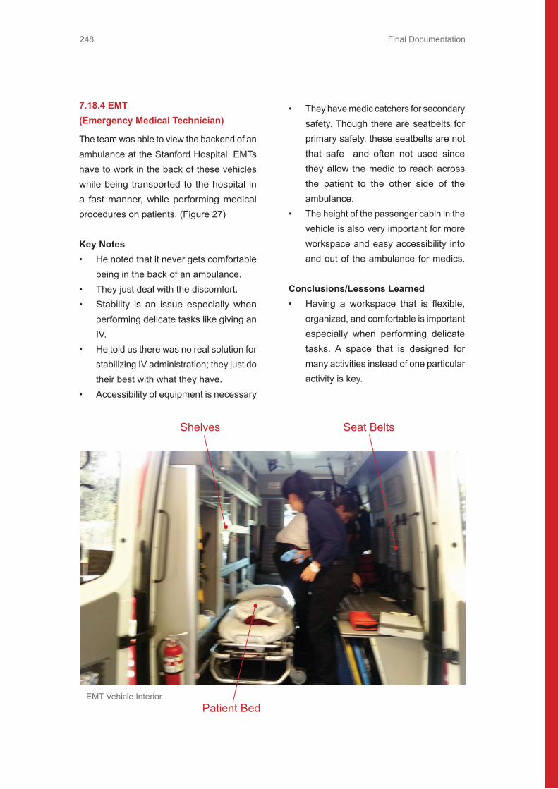
Final Documentation248
7.18.4 EMT (Emergency Medical Technician)
The team was able to view the backend of an ambulance at the Stanford Hospital. EMTs have to work in the back of these vehicles while being transported to the hospital in a fast manner, while performing medical procedures on patients. (Figure 27)
Key Notes• He noted that it never gets comfortable
being in the back of an ambulance.• They just deal with the discomfort.• Stability is an issue especially when
performing delicate tasks like giving an IV.
• He told us there was no real solution for stabilizing IV administration; they just do their best with what they have.
• Accessibility of equipment is necessary
• They have medic catchers for secondary safety. Though there are seatbelts for primary safety, these seatbelts are not that safe and often not used since they allow the medic to reach across the patient to the other side of the ambulance.
• The height of the passenger cabin in the vehicle is also very important for more workspace and easy accessibility into and out of the ambulance for medics.
Conclusions/Lessons Learned• Having a workspace that is flexible,
organized, and comfortable is important especially when performing delicate tasks. A space that is designed for many activities instead of one particular activity is key.
Seat BeltsShelves
Patient BedEMT Vehicle Interior

Final Documentation 249
7.18.5 Survey
To discover users’ potential needs while driving or riding a car, the team created a survey about the current drivers’ driving habits, their favorite activities inside a vehicle, and unpleasant moments they have experienced as a driver or a passenger. The survey has 9 questions with no direct indication of autonomous driving. It was sent out to our Facebook friends.(Figure 28: Servey Results)
Results• 62 responses. 77% of them are in the
age group 18-26. 21% of them are in the age group 27-35. 39% are female. 61% are male.
• Females enjoy driving because of: privacy, easy door-to-door transportation, music, good scenery, and hanging out with friends.
• Males enjoy driving because of: enjoy their own time, enjoy driving at the limits like speed and drifting, feeling of control
• Some crazy things they would like to do in the car: massage chairs, stretch, sleep, watch a movie, hang out with people in the back seat, prepare food, read, text while driving, shower, surfing the internet, and gaming.
• 60% of survey takers get motion sick while reading in the back of the car and on a bus. More than 80% of survey takers never get motion sick while reading in a train, metro, or plane.

Final Documentation250
How often do you feel motion sick while reading in the following vehicles - Plane?
How often do you feel motion sick while reading in the following vehicles - Metro?
Always Sometimes Hardly
3653
5%10%85%
Always
Sometimes
Hardly
0 11 22 33 44 55
Always Sometimes Hardly
0953
0%15%85%
Always
Sometimes
Hardly
0 11 22 33 44 55
What is your age?
18 - 26 (18)27 - 35 (13)
36 - 45 (1)
18 - 26 48 77%27 - 35 13 21%27 - 35 1 2%
What is your gender?
Male (38)
Female (24)
Female 24 39%Male 38 61%

Final Documentation 251
How often do you feel motion sick while reading in the following vehicles - Car front seat?
How often do you feel motion sick while reading in the following vehicles - Car back seat?
How often do you feel motion sick while reading in the following vehicles - Bus?
How often do you feel motion sick while reading in the following vehicles - Train?
Always Sometimes Hardly
91340
15%21%65%
Always
Sometimes
Hardly
0 8 16 24 32 40
Always Sometimes Hardly
152225
24%35%40%
Always
Sometimes
Hardly
0 5 10 15 20 25
Always Sometimes Hardly
92726
15%44%42%
Always
Sometimes
Hardly
0 10 15 20 25 305
Always Sometimes Hardly
21050
3%16%81%
Always
Sometimes
Hardly
0 10 20 30 40 50

Final Documentation252
Conclusions / Lessons Learned• People want more comfortable setup
and more space in the car• People want more communication and
engagement with other passengers.• People want to experience dangerous
driving mode without sacrificing safety.• People want to use their time more
efficiently in long driving trip (multi-tasking)
• People don’t want to drive in situations like: boring scenery, long waiting, parking
Phone calling & texting
Internet surfing through mobile phone
Listening to music
Mobile gaming
Reading
Working (laptop or paper)
Chatting with friends
Eating and drinking beverage
Drinking alcohol
Changing clothes
Putting on make-up
Other
Phone calling & textingInternet surfing through...Listening to musicMobile gamingReadingWorking (laptop or paper)Chatting with friendsEating and drinking beverageDrinking alcoholChanging clothesPutting on make-upOther
People may select more than one checkbox, so percentages may add up to more than 100%
614961384229555527391418
98%79%98%61%68%47%89%89%44%63%23%29%
0 24 36 48 60 7212
As a passenger, what kind of thing have you done inside a vehicle?

Final Documentation 253
7.19 Benchmarking From the brainstorming sessions that the team conducted, there were many areas of interest that needed to be explored for benchmarking. Benchmarking is an exercise of exploring as many areas as possible that relate to the problem statement, such as technology research, predictions, etc. Along with needfinding these two form the base of design. The areas areas for benchmarking included: trust, workspace,
Trust
Benchmarking
Steering
WokspaceConfirmationCues
TransitionMotion
Sickness
transition, steering, motion sickness, and confirmation cues. The team identified that the areas of interests could be separated into three categories:
1. Physical – Steering and transition2. Psychological – Trust and confirmation
cues3. Cabin/Environment – Motion sickness
and workspace

Final Documentation254
7.19.1 Steering Benchmarking
The team investigated various methods that could be used as steering mechanisms for vehicles. The methods include: gestural, mind control, voice commands, and haptic feedback. The steering benchmarking was defined as a physical aspect of the design and these ways of steering mechanisms could possibly show a more intuitive and effective way to transition from autonomous to manual mode instead of using the traditional steering wheel.
Gestural Steering Benchmark
In order to understand what it would feel like to drive using gestural commands, the team tried out an Xbox Kinect dancing game to see if gestures would be efficient to control.(Figure 30)
Observations• There was noticeable reaction time
between the dancer and the person mimicking the moves of the dancers
• Same concept applies semi-autonomous features which has a “guide” to follow in order to help maneuver
• Initial training and warm up is needed to get acclimated to the system
• Need to have some built in error allowance so the user has a better chance at mimicking the commands
Conclusions/InsightsThere are several insights that came from benchmarking a gesture-based system. A gesture based steering system can work if the reaction time between the gesture and response is minimized for best performance. There also would be a learning curve associated with this system. A training mode can be implemented as a “guide” to follow system to help the users get familiar with the system and gain more confidence, but need to compensate if the user cannot mimic the actions precisely.
Mind Control Benchmark
One non-obvious steering mechanism
that the team brainstormed was the use of mind control. Being able to steer using brainwaves and mind control is advanced, but has the possibility to eliminate any physical steering mechanisms completely. The team tested this idea by playing the game Mindflex. It reads the levels of concentration from sensors in the headsets
Gestural Steering Benchmark

Final Documentation 255
Mind Control Benchmark
and uses that to control the altitude of a ball as well as whether it travels forward or backwards along a track. It is comparable to how an EEG machine operates and senses a patient’s vital signs. (Figure 31)
Observations• Being able to isolate your concentration
to particular tasks is not easy.• Only one task can be done at a time,
hard to concentrate on two things at once.
• Once at extremes of high or low concentration it is hard to move the other way.
• It is possible to train yourself to control it properly based on the feedback of concentration levels.
ConclusionsAlthough the mindflex game was a great way to test out mind control activities, it was concluded that it is a very ineffective way for a steering mechanism, since it was hard to concentrate on performing simple tasks (i.e. moving a ball up or down, forward or backwards). It would be not feasible to apply this method to complex tasks and steering within a vehicle, even though it is possible to train yourself to control and concentrate properly.

Final Documentation256
Voice Command Steering Benchmark
To evaluate how effective a user can steer based on voice commands, the team set up a blindfolded driving experiment. The experiment was performed in an empty parking lot on Stanford campus in which the passenger guided the driver with their voice. The team tested whether the drivers trust themselves to perform this task and the “vehicle” to provide correct information. This helped to illuminate what types of cues should be used in order to assist in a transition or to allow more flexibility in the driver position so that it is not necessary to be looking out the windshield when driving.(Figure 32: Blindfolded Test)
Observations• Hard to figure out if the steering wheel
was straightened out. It was also difficult for the driver to drive in a straight path, as they could not tell when to make the slight adjustments that were necessary.
• Difficult to tell whether we were even moving (since moving at slow coasting speeds).
• It was very disorienting and made the driver feel slightly off balance or uneasy.
• Driver wanted some type of orientation cues to understand why they were being told to do certain tasks
• Driver was very hesitant to go fast even when told to just go straight.
• Driver did not trust his or her own reaction time to the commands.
• When told to turn left, the drivers would not turn all the way to left. Instead they
would do smaller incremental operations while turning left.
• Became easier when the voice commands used qualifiers like “hard left” to indicate the driver should turn the wheel a lot.
• Interpretation of the commands was very clear.
ConclusionsSeveral insightful conclusions were brought up with this benchmarking idea. The voice based steering functionality is not effective since appropriate feedback and confirmation cues were not provided. This leads to trust issues and the driver feeling unsafe with the situation. Although the voice commands were clear and concise (left, right, hard left, hard right), it was hard for the driver to determine to what degree the command should be taken. A hard right or left is very ambiguous, especially when there are many factors associated with driving including speed, obstacles in the road, and the sensitivity of steering for a particular car. The number of levels in a steering feature/mechanism is important to be able to make small or large changes. The user input in current mechanical steering design in cars is a continuously varying input, as compared to certain discrete degrees of input in the voice commands based on the phrases used. The ideal number of degrees required to steer will fall somewhere in between. Another important conclusion is that different drivers would respond differently to such a system based on past behavioral experiences. This leads to the issues of past experiences affecting driver psychology.

Final Documentation 257Final Documentation 257
Blindfolded Test
Haptic Command Steering Benchmark
The haptic command steering benchmark was part of the same experiment and set up like the voice command steering benchmark. Since it was hard to determine what degree of steering should be mapped to the voice commands (left, right, hard left, hard right), haptic feedback, the team hypothesized, should provide better commands in terms of interpretation. This benchmark only used haptic command and not voice commands. Tapping on the right shoulder meant to turn right and tapping on the left shoulder meant to turn left. To indicate to drive straight, both shoulders were tapped. To indicate stop, both shoulders were pressed down on at the same time. By tapping faster on the shoulders with turning or going straight, the driver knew to what degree it should be done. (Figure 33)
Observations
• The reaction time was longer in terms of noting the difference in command or when to stop doing one thing and start doing another.
• The transition from one command to another was not distinct enough.
• Harder to perform when there were a lot of tapping tasks happening one after another
• Signals could be interpreted in different ways by different drivers, for instance the stop tap signal could also be interpreted as a rapidly accelerate signal.
• It was uncomfortable and annoying after long periods of driving.
• A lot of concentration and focus was needed to interpret/process the tapping task and then to respond to the task.

Final Documentation258
ConclusionsCompared to the voice command steering benchmark, although the reaction time to interpret, process, and respond to the tapping tasks was longer, the degree of mapping of steering to the haptic feedback seemed to be more effective than the voice commands. Haptic and voice commands are possible solutions steering mechanisms, but more indicators to alert the driver prior to the actual command would allow the driver to anticipate the command (turning or driving straight). Visual feedback still seems to be the ultimate solution since the driver can process the visual data faster and be able to see the environment prior to it happening.
Haptic Command Benchmark
Segway benchmarking
The team realized that in order for the drivers to quickly take over the controls, the control mechanism must be very easy to learn. The team looked for an existing example of a generally perceived intuitive vehicle in order to isolate what was essential to make a steering method intuitive.
A local entertainment center was contacted and a time was scheduled to test Segways. Segway uses unique steering method and thus could be one of the future steering directions. In order to go forward or backward the driver needs to lean forward or backward accordingly. Pulling the handle in front of the driver to the left or right does the steering left and right. The steering handle serves also as a help to balance the driver during the ride.(Figure 34)
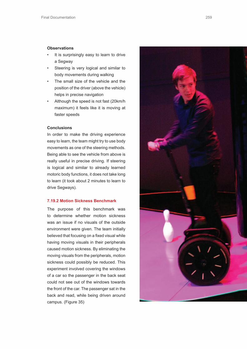
Final Documentation 259
Observations• It is surprisingly easy to learn to drive
a Segway• Steering is very logical and similar to
body movements during walking• The small size of the vehicle and the
position of the driver (above the vehicle) helps in precise navigation
• Although the speed is not fast (20km/h maximum) it feels like it is moving at faster speeds
ConclusionsIn order to make the driving experience easy to learn, the team might try to use body movements as one of the steering methods. Being able to see the vehicle from above is really useful in precise driving. If steering is logical and similar to already learned motoric body functions, it does not take long to learn (it took about 2 minutes to learn to drive Segways).
7.19.2 Motion Sickness Benchmark
The purpose of this benchmark was to determine whether motion sickness was an issue if no visuals of the outside environment were given. The team initially believed that focusing on a fixed visual while having moving visuals in their peripherals caused motion sickness. By eliminating the moving visuals from the peripherals, motion sickness could possibly be reduced. This experiment involved covering the windows of a car so the passenger in the back seat could not see out of the windows towards the front of the car. The passenger sat in the back and read, while being driven around campus. (Figure 35)

Final Documentation260
Observations• Within 5 minutes of reading in the car,
passenger felt motion sick, even with people who never experienced motion sickness in the past
• Good ventilation and lighting may have been a factor – the garbage bags blocked off airflow to the where the passenger was riding and lighting produced moving shadows
• May have been due to the extreme driving that the tester was doing as well
• Very difficult to read because you could not anticipate turns or stopping
ConclusionsFrom our initial beliefs, motion sickness was still an issue even with the surrounding environment visuals being blocked. Other factors within our experimental set-up could have induced the motion sickness problem. In this case, the remedy would probably be to have screens for everyone to see out from the front into the horizon. Some sort of visual and anticipatory feedback is necessary to avoid motion sickness while doing work in the car. Some options to explore would be whether the complete view is required or only the view from one side of the car is sufficient. The problem with this is that in metropolitan cities, having the view of buildings zooming past the side could make people more motion sick. Motion sickness is definitely a problem and can be considered an extension to the team’s design vision since the cabin space will be designed to accommodate users doing desired activities.
Motion Sickness Benchmark
7.19.3 Human-Machine Transition Benchmarking
The driver transition between autonomous and driving mode is an important aspect and area of interest. To be able to determine the steps that should be taken prior and during the transition, the team observed two different events that simulate the human-machine interaction transition.
CNC Machine Operation ObservationThe team observed fellow students using CNC machines in the workshops to view a scenario in which humans transfer control to a machine. The team hoped to learn about what kind of procedures occur before the students transfer controls, what happens when something goes wrong, and how they transfer control back to themselves.

Final Documentation 261
Observations• Dry runs of the actual program were
performed first before the final cut to ensure the program worked properly. During the dry run the speeds could be controlled to be at 25%, 50% and 100% of the actual cutting speed for visual inspection.
• Operator always had hands on the “stop” button
• When something went wrong and did not know how to fix the problem, the operator had to wait for a TA
• The operator frequently doubled checked that the correct drilling tool was inserted.
ConclusionsThe team observed that repeated visual inspections and routines were performed initially to make sure that the program was correct and doing what it is suppose to do. In the situation of autonomous cars breaking down, having some kind of immediate service or real-time diagnostic analysis can be performed on the spot. A major finding was that dry runs with controlled speeds could be extrapolated as building gradual trust with the autonomous system. It can either be different percent of manual control and gradual shift to autonomous thus building complete trust or it can also be in completely autonomous mode with different levels of maximum speed. Trust in the system and having self-confidence that it is working properly is a main concern, but gradually maintaining that trust is important. Even though this experiment was focused on the transition between human and machine, it opened up many questions in terms of developing trust. (Figure 36)machine, it opened up many questions in terms of developing trust. (Figure 36)

Final Documentation262
Racing Game Player-to-Player Transition
In order to understand what it would feel like to take over control of driving after being in autonomous mode, the team decided to experience this using a racing video game. One player would drive the route in the game, and then quickly give control over to another player. (Figure 37)
Observations• Easier to switch if the other player was
observing what was going on• If the next player was not paying
attention, the chances of crashing increased dramatically
ConclusionsFrom this experience, it seemed obvious that a gradual shift of control is probably better so that the drivers are aware of the surrounding environments and of the vehicle’s control actions. This way the driver can align themselves or the controls in that direction. An incremental rather than a direct transition of controls would allow the driver to get acclimated with what is happening around them.
7.19.4 Confirmation Cue BenchmarkingConfirmation cue benchmarking is essential in determining the psychological effects of a driver in an autonomous car. Being able to maximize the enjoyment of the riding experience is important while also keeping the user aware of the surrounding environments and vehicle’s control actions.
Racing Game Player to Player Transition

Final Documentation 263
Console in the car that indicated left, straight, right (posts were replaced for speed bump, sharp turn, braking indictors)
Light Indictor Experiment
The team wanted to test and understand how much information would be needed for the passenger in an autonomous car to ride comfortably when all visual cues (i.e. seeing out a window) are gone. The experiment involved a passenger in the back seat of the car in which they could not see out any window or through the front of the car. A console was lit up to indicate specific actions of the car or surrounding environment prior to the actions occurring. Two versions of this experiment setup was tested (Figure 38):
1. Console lit up to indicate what direction is being traveled (i.e. turning left, right, driving straight)
2. Console lit up to indicate the speed at which the car is travelling (i.e. slow to fast)
3. Console lit up to indicate in advance when something out of the ordinary was going to happen (i.e. speed bump, sharp turn, sudden braking)
Observations• Left/Right & Speed Indicators were not
really useful because the passenger felt the motion. In this case, real time indication is not useful.
• Speed Bump, Sharp Turn and Braking signs were effective because it gave advance warning and was not real time.
• One downside of this light system was that the passenger had to be looking at it to know, which made it irrelevant when trying to do something else in the car
• When the light wasn’t indicating
anything, it made the passenger feel like the system wasn’t working or wasn’t quite sure what was going on.
ConclusionsAlthough the indicators seemed to be effective at times, user acceptability will depend a lot on the type and the amount of information relayed, and how intrusive it is when doing desired activities inside the car during autonomous mode. One possible further benchmarking to explore would be to understand the different tasks being performed in the autonomous car and finding a non-intrusive and effective way of giving notifications to the user. By having anticipatory cues for out of the ordinary situations, it will lead to reassurance that everything is working fine.
Final Documentation264
Voice Indictor Experiment
The team not only tested how visual confirmation cues affect how a passenger is notified about the surrounding environments and of the vehicle’s control actions, but with the use of voice indicators as well. The motivation of this was to see whether giving only audio cues could provide the passenger with enough information for them to feel secure. The experiment setup used the same setup from the light indicator experiment, but the console did not project anything. The rider in the front of the car would say what is about to happen, for example, “stop approaching”.
Observations• Voice is nice because it gives a more
precise description of what is going on.• Feels more secure and reassuring.• One concern is whether it is too intrusive
when music is being played or in general.
ConclusionsCompared to the light indicator experiment, the voice indicator seemed to be more effective. User acceptability will still depend on the type and the amount of information relayed and how intrusive it is when doing desired activities inside the car during autonomous mode. The interface with which the user interacts should maximize the enjoyment of the riding experience but still allow the user to be aware of what’s happening around them.

Final Documentation 265
7.19.5 Trust benchmarking
There are various assistive driving technologies implemented in current high tech cars that allow the driver to be in less control. By benchmarking and experiencing existing driver assist technologies, it will give the team a better understanding of how and why drivers will be able to trust autonomous vehicles in the future.
Adaptive Cruise Control (ACC)
The ACC was tested within a Porsche Panamera to show what feedback is given currently to help ease the driver’s concerns about giving up control of the pedals. The team was interested in finding out how the driver engages the feature and how to disengage or override the feature. It also helped the team to experience what it feels like to give up control in a way that the team is not accustomed to. (Figure 39)
Observations• There was no feedback letting the driver
know that the ACC was working.• No visual indicating how far away from
the car in front or that the car intended to stop.
• Easy to transition to using ACC by using a lever to push in and a scroll wheel to decide what the desired following distance was.
• Override it at any time by pressing on the accelerator or brake.
• The visual of whether a car was in front or not was helpful, as well as, the following distance setting visual
• Location on dashboard of the visual was very convenient and only slightly distracting
ACC ControlPanamera Dashboard

Final Documentation266
ConclusionsIt is important to have feedback to know that the system is working and what it plans on doing to make the driver feel comfortable enough to relax and not be too vigilant by watching over the car. If the user sees what the car sees, then trust is built.
Parking Assistant
The parking assistant in the Porsche Panamera has another feature that gave the user more control and awareness while parking. The display had yellow lines to show the cars projected path according to the position of the steering wheel and has sensors to notify the driver how close the car is to an object. A beeping noise sounded when the car was very close to hitting something. (Figure 40: Parking assistant display while backing up)
Observations• This is very helpful in knowing if you are
turning the wheel properly, especially for parallel parking.
• The sensor/ beeping is slightly annoying.• It is very cautious and drivers realize that
even though the visual is red, they can still move further.
• The display of the car and colors showing proximity to an object is very intuitive and easy to understand.
ConclusionsThe display of information on top of a real-time image of the actual environment was very effective for parking and driving in reverse during low speed activities. Although
the sounds are effective in alerting the driver, it can get annoying. The interface that the driver interacts with is a crucial part in the riding and driving experience, but being able to trust the system’s autonomous functions are important too
Night Vision
The night vision assistance in the Audi A6 and A7 models is displayed on the dashboard of the car. It is meant to help drivers at night be able to easily identify obstacles in their path that should be avoided. When a pedestrian is identified, they are highlighted with a red outline to give the driver an alert that there is something in the road ahead.(Figure 41)
Observations• The use of infrared cameras is very
good• The image is clear, and the alerts and
identification works relatively well
ConclusionsAlthough the systems works properly and effectively, it is a little distracting since the display was bright at night and within your peripheral view which could draw your eyes away from the actual road. It is possible that it could be more helpful in nighttime/daytime driving in fog, snow, rain, or other hazardous weather conditions.
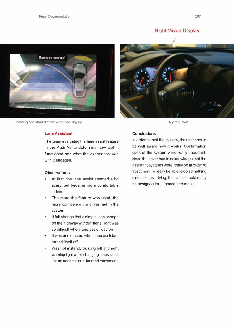
Final Documentation 267
Night Vision Display
Parking Assistant display while backing up Night VIsion
Lane Assistant
The team evaluated the lane assist feature in the Audi A6 to determine how well it functioned and what the experience was with it engaged.
Observations• At first, the lane assist seemed a bit
scary, but became more comfortable in time
• The more the feature was used, the more confidence the driver had in the system
• It felt strange that a simple lane change on the highway without signal light was so difficult when lane assist was on
• It was unexpected when lane assistant turned itself off
• Was not instantly trusting left and right warning light while changing lanes since it is an unconscious, learned movement.
ConclusionsIn order to trust the system, the user should be well aware how it works. Confirmation cues of the system were really important, since the driver has to acknowledge that the assistant systems were really on in order to trust them. To really be able to do something else besides driving, the cabin should really be designed for it (space and tools).

Final Documentation268
Night Vision Display Camera
CameraDisplay
Audi A8 Equipment

Final Documentation 269
Audi S8 2013 Benchmarking
The team got the chance to experience the most expensive camera system (Audi Pre Sense Plus) that Audi has to offer. This gave a good insight of the current state of camera technology in the cars and how it is used for modeling the surroundings of the car. (Figure 42)
Observations• Nowadays cameras can be quite useful
for observing the surroundings• Cameras make it possible for the
computer to model the surroundings• Corner cameras help to see what is
happening around the corner• If a person is walking to the front of the
moving car the human shape will turn to red to warn the driver
• The car tries to recognize human shapes in the surroundings (it cannot recognize animals yet)
ConclusionsIn the future, computers will be able to combine multiple sources of information so that car will have better awareness of its surroundings than a human driver. The future car will most likely be able to predict and calculate many different scenarios of what will happen while driving.

Final Documentation270
7.20 Critical PrototypesCritical prototypes are physical prototypes uses in ME310 to identify critical functions and experiences. Therefore critical prototypes are divided into CFP (Critical Function Prototype) and CEP (Critical Experience Prototype). CFP is a physical prototype of a fundamental element of design, which is required to ensure its functionality and CEP is a physical prototype of an experience of design, which is required
to ensure usability.
7.20.1 Critical Function Prototype - “Transition Golf Cart” (Figure 43)
Driver comfort, safety and ease of transition are important issues during transitioning between autonomous driving and manual driving for an autonomous car. It is important to test the sequence of actions that would take place and the kind of interface that the drivers would interact with during the actual transition.The critical function being tested in this prototype is the transition from autonomous to manual. Situational awareness and being in line with the actions being applied by the autonomous controller are important for a smooth and safe transition. That is why the team implemented the concept of
Golf Cart Prototype

Final Documentation 271
Display
Switch
guided matching of controls (steering and throttle) during and after transition. This was implemented by setting up a golf cart with a transition switch and an interface in front of the users which prompts them to mimic the actions of the autonomous controller. The hypothesis being that such a guided matching interface will lead to increased situational awareness of the user leading to a comfortable transition. Autonomous mode was faked using a passenger seat driver. The actions of the autonomous controller were displayed based on pre-recorded data on the same track for driving. The details of the setup can be found in appendices.
Golf Cart Prototype Driving
With Transition Golf Cart we tried to answer to following questions:1. Do people feel safe and comfortable
making this transition using the prototype?
2. Does the setup increase situational awareness for the driver?
3. Are people good at matching?4. Is the interface to intuitive?5. What is the appropriate amount of
time required to make this transition safely?
6. Is visual representation a good way of conveying information to the driver during driving?

Final Documentation272
The two types of transition sequences that were tested using this prototype were (Figure 45):
1) Gradual TransitionThe user is given control of the pedals first and a matching task is initiated. Once a certain degree of accuracy is achieved in matching the autonomous control actions, the user is given the control of the steering as well and a similar matching task is initiated. After matching the steering, the car goes into completely manual mode.
2) Direct TransitionThe user is given control of both the control inputs at the same time and a simultaneous matching task is initiated. Once the user is comfortable in matching, the interface goes away and the car goes into completely manual mode.
AutonomousMode
AutonomousMode
TransitionInitiated
TransitionInitiated
+
Match Match
Match
ManualMode
ManualMode
Gradual Transition
Direct Transition
Gradual and Manual Transition Transfer Sequences

Final Documentation 273
Observations Conclusions
Users did not feel like driving and feltunsafe during both the transitionsequences. People are more engaged in thematching task than driving which issupposed to be the primary task inmanual mode
The interactive interface was too distractingduring driving and it needs to blend with theenvironment more easily. Visualrepresentation of information is too intrusiveduring driving.
In the gradual transition, once the usersare given the both the steering and pedalsin step 2, they neglect pedals completelyduring steering matching
People are better at doing simultaneousmatching than matching the control inputsone at a time
Matching error for the entire transitionsequence is lower for the direct transition.
People are better at doing simultaneousmatching than matching the control inputsone at a time
Users felt safe and more comfortable in the direct transition
This might be because of the lower transition time in the direct sequence. The longer process involved in the gradual transition delays complete situational awareness.
In the gradual transition, the users had a tendency to grab the steering wheel as soon as they switched to manual
The reason for this might be that having a feeling of controlling the more sensitive input, which is steering, makes the users feel safe.
Gradual Direct
Step 1
Pedal Matching Simultaneous Matching
TargetRegionsSteering Matching
Step 2
Golf Cart Prototype Obeservations and Conclusions

Final Documentation274
inputs from both the sources and that they would control the pedals based on feedback from the environment. However as observed before, the visual interface was too distracting and the pedal control was essentially an open loop. This was confirmed by the fact that the car came to a complete stop at times during steering matching which meant that pedal control was being completely ignored. On the other hand, in the direct transition, the source of information for both the control inputs was the interface and the environment
The results were surprising because people were better at and more comfortable with performing multiple tasks at the same time than doing one task at a time. The reason for this was based on how information is processed from various sources. As can be seen in the flowcharts in Figure 46, there are two sources of information involved – the interface and the environment.
In the gradual transition, as shown in the flowchart, it was expected that the users would control the steering based on the
Interface
Interface
Interface
Interface
Environment
Environment
Environment
Environment
Direct Transition - Expected
Gradual Transition - Expected
Direct Transition - Results
Gradual Transition - Results
Transition Sequence Flowchart

Final Documentation 275
7.20.2 Steering Mechanisms
Steering and pedals have traditionally been the primary control inputs in automotive design. When designing the cabin space and transition interface for an autonomous car of the future, it might be desirable to explore other designs for control inputs that will make driving more fun and be easier and comfortable to transition to from any other activity that is being performed in the car space during autonomous mode. Having a new control input might also open up new options for cabin space design. This new control input needs to be intuitive to use and the users should be able to clearly and comfortably convey their intentions to the car controller.To test this idea, the team hooked up different steering controllers to car gaming interfaces and users tried to steer the car with these non-conventional control inputs. A pre-interview was conducted to understand the driving habits and experiences of the user. After the user tried out each of the prototypes, a post test survey was conducted which gathered information on the comfort level of that particular method of steering and its intuitiveness. The different types of steering control inputs that were tested in this prototype are:
• Small hand controller• Steering with feet• Total joystick control• Joystick and control buttons mixed• Tilting feet to steer
was completely ignored. But the user’s performance was still better because there was just one source of information. Performance is not based on the number of tasks being performed at the same time but on the coherence between the sources of information. As shown in the flowcharts, the ideal solution would lie where the source of information overlaps between the interface and environment. Thus in the ideal solution, the interface blends in with environment perfectly so that the goal of maintaining situational awareness while making the users feel safe and comfortable is achieved.
Interface Environment
Ideal Transition

Final Documentation276
Based on the motivation for this CFP and some initial ideas, the team came up with certain requirements that need to be satisfied by a good control input design. Metrics for testing these requirements were identified based on the car gaming interface setup for this prototype.
Small hand controller
We used a normal Playstation Joystick tigh a small steering stick which is used with thumb movements. After initial testing with users, we quickly realized that the tested steering method is not satisfying our needs and we quickly discarded it. Driving was way too imprecise using this method. (Figure 47)
Steering with feet
We wanted to test if steering with feet can be a more intuitive alternative to conventional steering methods. We purchased a steering wheel game controller with pedals and set up the game so that the turning left and right is done by pressing left and right pedal and acceleration and braking is done by pressing buttons on the steering wheel. Turning the wheel doesn’t effect the game whatsoever.(Figure 48)
Observations• Turning was really difficult. Users didn’’t
know how hard they should press the pedals.
• Feet do not respond as quickly as hands in such a dynamic situation.
• The throttle button was binary and it created some problems for the users. Many of them wished to control the speed better.
• Having the steering wheel in front of the users, without having any function was confusing. (The setting had a steering wheel on the table where one button is acceleration and turning was done by feet by pressing left and right pedal)
Small Hand Controller
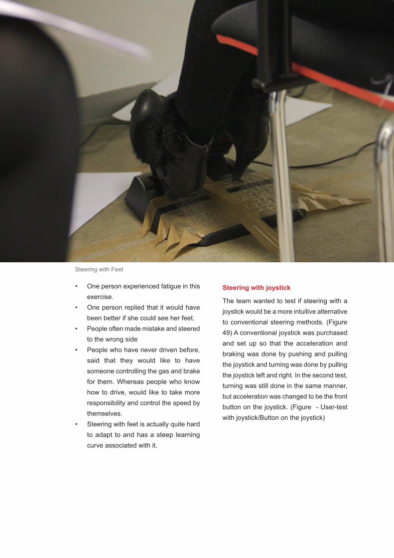
Final Documentation 277
Steering with joystick
The team wanted to test if steering with a joystick would be a more intuitive alternative to conventional steering methods. (Figure 49) A conventional joystick was purchased and set up so that the acceleration and braking was done by pushing and pulling the joystick and turning was done by pulling the joystick left and right. In the second test, turning was still done in the same manner, but acceleration was changed to be the front button on the joystick. (Figure - User-test with joystick/Button on the joystick)
• One person experienced fatigue in this exercise.
• One person replied that it would have been better if she could see her feet.
• People often made mistake and steered to the wrong side
• People who have never driven before, said that they would like to have someone controlling the gas and brake for them. Whereas people who know how to drive, would like to take more responsibility and control the speed by themselves.
• Steering with feet is actually quite hard to adapt to and has a steep learning curve associated with it.
Steering with Feet
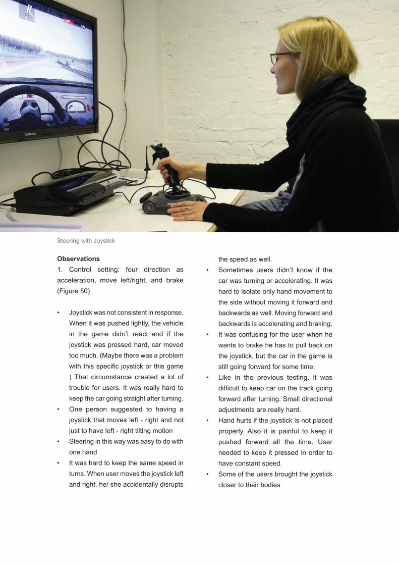
Final Documentation278
the speed as well.• Sometimes users didn’t know if the
car was turning or accelerating. It was hard to isolate only hand movement to the side without moving it forward and backwards as well. Moving forward and backwards is accelerating and braking.
• It was confusing for the user when he wants to brake he has to pull back on the joystick, but the car in the game is still going forward for some time.
• Like in the previous testing, it was difficult to keep car on the track going forward after turning. Small directional adjustments are really hard.
• Hand hurts if the joystick is not placed properly. Also it is painful to keep it pushed forward all the time. User needed to keep it pressed in order to have constant speed.
• Some of the users brought the joystick closer to their bodies
Observations1. Control setting: four direction as acceleration, move left/right, and brake (Figure 50)
• Joystick was not consistent in response. When it was pushed lightly, the vehicle in the game didn’t react and if the joystick was pressed hard, car moved too much. (Maybe there was a problem with this specific joystick or this game ) That circumstance created a lot of trouble for users. It was really hard to keep the car going straight after turning.
• One person suggested to having a joystick that moves left - right and not just to have left - right tilting motion
• Steering in this way was easy to do with one hand
• It was hard to keep the same speed in turns. When user moves the joystick left and right, he/ she accidentally disrupts
Steering with Joystick

Final Documentation 279
2. Control setting: joystick left/right to control turning, buttons to control gas & brake
• Some users were performing better if they have gas and brake separated from turning movements. One person improved by 20 sec per lap after this adjustment. (Often they were still pushing the joystick forward even if that had no effect on the game.)
• One guy suggested that it would be better to have a speed limit and try driving like that.
• Braking button was not analog, so it was always braking maximally instead of slowing down the car.
• Going backwards with a separated button is confusing and it takes time to realize what to do and where the button for reverse is.
• When users were able to see the whole car, they almost didn’t crash at all. However, in top view it is hard to see how much the car turns, because user can’t see the wheels in front of the car.
Accelerate
Accelerate
Brake
Brake
Right
Right
Left
Left
1 .Control setting
2 .Control setting

Final Documentation280
Tilting Feet
The team wanted to simulated Segway-like -steering for this prototype. In this tilting feet setup the car was steered with tilting feet to simulate the intuitiveness of a Segway. (Figure 51)
Observations• Accelerating same time with tilting
forward and steering proved to be almost impossible
• Joystick position on the floor was almost impossible to put in a way that is comfortable to steer with
• It took too much effort to tilt the joystick to its full extent with just feet.
Tilting Feet Controller

Final Documentation 281
Another insight is that listed requirements should not be applied in our context since we realized that the intuitiveness is not really an issue. These steering methods can also be tested in perspective of fun in the future.
Opportunities• Steering, accelerating, and braking is
entertainment that cannot be done the same way in anywhere else. Simulators and games are always missing some parts of the holistic experience.
• The intuitiveness is not the issue, since driving safely will be enhanced with active safety systems that autonomous car and its infrastructure can provide. It might also be safe to assume that passive safety systems (seat-belts, airbags, etc.) can be removed and the freedom of cabin design is increased.
Conclusions / Lessons Learned from CFPThe assumed purpose of this prototype proved to be quite irrelevant. It was discovered that none of the non-conventional steering options are that precise and all of them have a steep learning curve associated with them. However, the most interesting insight from this prototype was that manual driving is redefined in the future with cars being semi-autonomous and crash proof. In such a situation, it might even be desirable to have a non-precise controller that gives the user an illusion of precise control while making driving more fun.
Almost all of the cars in the future will be part of the autonomous car system since if one person is allowed to drive outside the system and do unpredictable moves, the rest of the drivers will be in danger. This is why intuitiveness is not really an issue from the perspective of learning. After testing this prototype we will approach steering from another perspective: the fun perspective. Autonomous technologies make totally safe driving possible and driving in a semi-autonomous mode lets the driver to push the boundaries knowing there is no dangers in driving because the car takes care of safety. However the driver should not feel like the car is applying a lot of corrective action even in manual mode. That needs to be avoided since the team aims at maintaining the pleasure of driving through the proposed design.

Final Documentation282
7.20.3 Critical Experience Prototype - “Reconfigurable Workspace”
Workspace prototyping is an important aspect of the design. Since the driver will be in autonomous mode a majority of the time, being about to do the driver’s desired activities within the cabin space of the vehicle is ideal. The driver not only needs to be able to do their activities in the space, but it needs to be a comfortable and more intimate personalized experience.
The team wanted to explore the experience of having a moving chair in the cabin space of a car. The environment was setup to have a mock cabin space with movable chair to transition from driving to leisure mode.
To test this experience, the team made a quick prototype of the envisioned cabin space with an interactive windshield display and a moving chair for repositioning the user during autonomous mode to a location that has been adapted to perform some of the activities like working and relaxing. The prototype is shown in Figure 52. The details about how this prototype was tested have been included in.
Observations• The setup of the moving chair
transitioning to the cabin activity space table was an interesting feeling, not able to do that in current cars
• Position of person when moving forward or backwards in transition is awkward especially with the feet dangling
• Comfortable with space to be able to desired activities
• Timing may be a problem when trying to switch in transition suddenly, especially when the user wants to take control ASAP
Conclusions / Lessons Learned• It is desirable to have more room and
space to do various activities• Users noted that the experience was
not like being confined in a typical car• It was observed that the chair speed
affects the level of comfort users have with this setup. It has to be fast enough for a quick transition but slow enough to avoid discomfort.
• One interesting concept that came out of testing this prototype was that it might be good to have the steering apparatus attached to the moving chair so that you can control the car from any location and orientation within the car
• It would be desirable to have an interface that displays various configurations of the cabin space in an intuitive way for the user to interact with.
• Besides having a switch, there can be other ways of conveying the user’s intention to the controller like voice based and gesture based commands.

Final Documentation 283
InteractiveWindshield
Movable Chair
Cabin ActivitySpace
Reconfigurable Workspace
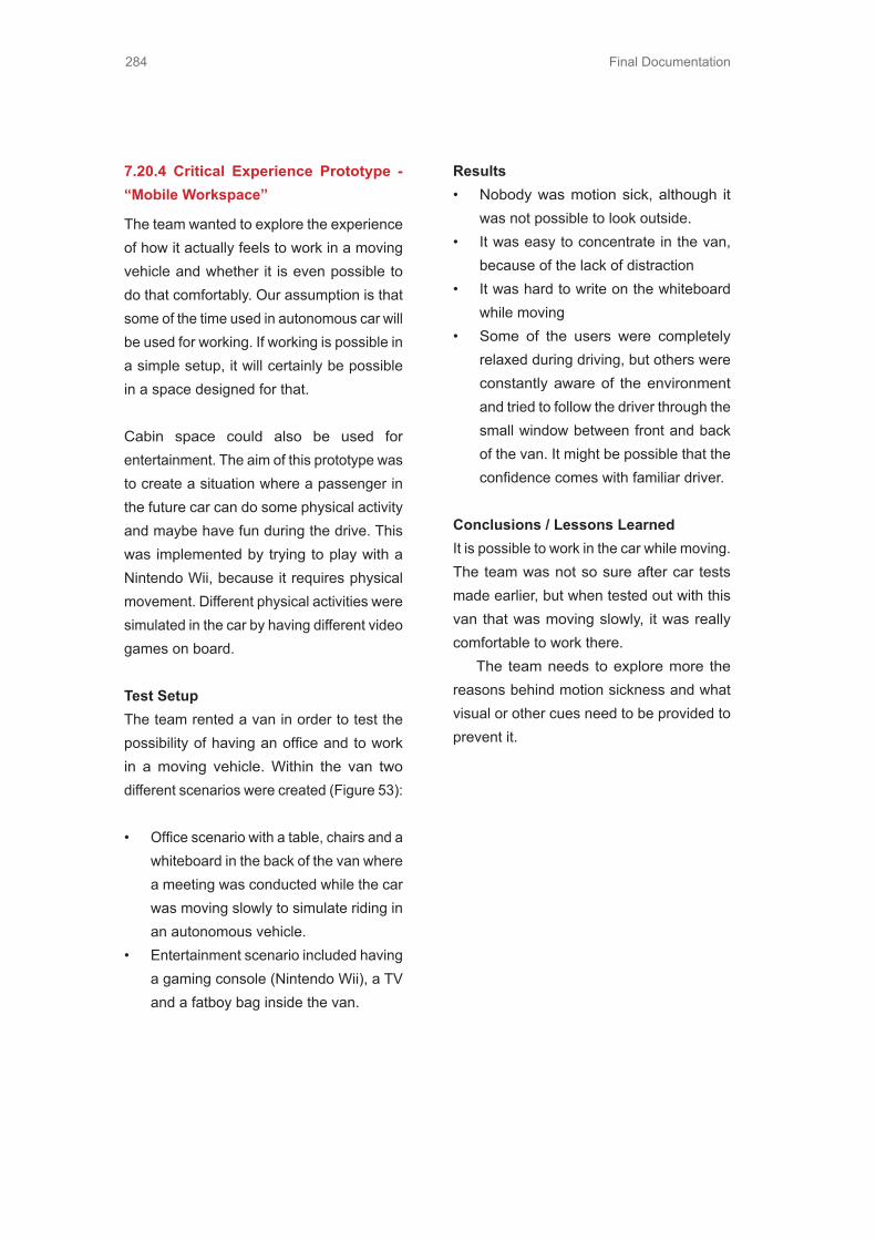
Final Documentation284
7.20.4 Critical Experience Prototype - “Mobile Workspace”
The team wanted to explore the experience of how it actually feels to work in a moving vehicle and whether it is even possible to do that comfortably. Our assumption is that some of the time used in autonomous car will be used for working. If working is possible in a simple setup, it will certainly be possible in a space designed for that.
Cabin space could also be used for entertainment. The aim of this prototype was to create a situation where a passenger in the future car can do some physical activity and maybe have fun during the drive. This was implemented by trying to play with a Nintendo Wii, because it requires physical movement. Different physical activities were simulated in the car by having different video games on board.
Test SetupThe team rented a van in order to test the possibility of having an office and to work in a moving vehicle. Within the van two different scenarios were created (Figure 53):
• Office scenario with a table, chairs and a whiteboard in the back of the van where a meeting was conducted while the car was moving slowly to simulate riding in an autonomous vehicle.
• Entertainment scenario included having a gaming console (Nintendo Wii), a TV and a fatboy bag inside the van.
Results• Nobody was motion sick, although it
was not possible to look outside.• It was easy to concentrate in the van,
because of the lack of distraction• It was hard to write on the whiteboard
while moving• Some of the users were completely
relaxed during driving, but others were constantly aware of the environment and tried to follow the driver through the small window between front and back of the van. It might be possible that the confidence comes with familiar driver.
Conclusions / Lessons LearnedIt is possible to work in the car while moving. The team was not so sure after car tests made earlier, but when tested out with this van that was moving slowly, it was really comfortable to work there. The team needs to explore more the reasons behind motion sickness and what visual or other cues need to be provided to prevent it.
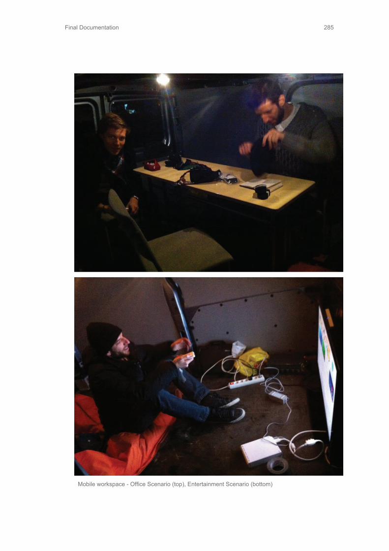
Final Documentation 285
Mobile workspace - Office Scenario (top), Entertainment Scenario (bottom)

Final Documentation286
7.21 Design Specifications As described in Section 4.5.6, one of our main CFPs was the one that tested out the transition sequence by simulating autonomous mode on a golf cart and prompting the user to mimic the actions of the autonomous controller for situational awareness. This section lists the design specifications and detailed description of this prototype.
7.21.1 Transition sequence prototype
The main objective of this prototype was to test the comfort level and intuitiveness of agradual or a direct transition from autonomous to manual mode. As described in Section 4.8.1, both the transition sequences consisted of real time data being displayed to the users and along with pre-recorded data that they were supposed to
follow to make the transition easier. This plan required real time information about the steering and pedals being displayed to the user. The following sections give details about the electronics and the coding strategy used. The entire code can be found in Appendix 7.6.2.
Mechanical SetupAs shown in Figure 54, the mechanical design for this prototype consisted of designing a means of indicating the desire to switch to manual from autonomous by using a switch. This switch needs to be placed in a comfortable and accessible position for the user. In this prototype this switch was mounted on the cover that was designed to protect all the electronic circuits that were mounted on the steering wheel of the golf cart. The proposed design for this prototype also required an interface right in front of the users while driving to prompt them to mimic
Transition Switch Display Construction

Final Documentation 287
Golf Cart Construction
the autonomous controller actions. A 7-inch tablet was used for this purpose as shown in Figure 55. To create a mount for this tablet, the team bent a sheet of acrylic to make it a holder for the tablet and added mounting clips on the same for securing it to the golf cart windshield right in front of the user. at the same time. The reason behind it was to learn about people’s working habits in a relaxed atmosphere.The way these two designed components were mounted on the golf cart has been shown in Figure 56. It should be noted that the laptop was just for real time serial communication with the sensors and kept on the passenger side of the car in a way that was not interfering with any of the user’s actions during testing.

Final Documentation288
As shown in Figure 57, below the electronics were mounted right on the steering wheelbeneath the designed component for protection from damage during testing. This also turned out to be a useful shield from rains during testing. The mechanical design allows the flexibility of flipping open the cover and working on the electronics if the designer wants to change something on the breadboard or check for lose connections.
Switch
Switch Contrustion

Final Documentation 289
Figure 58: Arduino Board
Description of the electronics
Arduino duemilanove microcontroller was used for receiving data from the sensors and communicating with the laptop. A software platform called iDisplay on Android was used to extend the screen of the laptop to the tablet for displaying the interface that was coded in Visual C# and which responded to the data received through serial communication with the Arduino board. There were two sensors used for getting the steering and pedal data respectively. There is an internal potentiometer mounted on the throttle pedal of the golf cart to give the throttle signal to its internal controller. There was an external tap created on the voltage reading of this potentiometer and the value was fed to the Arduino ADC. It should be noted that only one pedal (throttle) was used for this entire experiment and the brake pedal was not used. The analog input sample circuit has been shown in Figure 58.
The steering angle was detected using a maximum acceleration vector detection algorithm applied to the data received from the accelerometer ADXL345. The connections for this module have been shown in Figure 42 above. When the system is reset, it takes 5 seconds and notes down the stationary initial net vector (which is mainly just gravity). Once the algorithm starts, every time it calculates the angle of the current net vector with this initial vector and converts it to the steering angle. There are two ways in which we will get inaccurate readings from this method:
D13D12D11D10D9D8D7D6D5D4D3D2D1
D0
A0A1A2A3A4
A5
RST
AREF
Arduino
GND
3V3 5V Vin
• Acceleration of the car itself and sudden bumps will make the net accelerationvector jump around 65• Rotational acceleration while turning the steering wheel will also cause problems
However this was a basic prototype to show proof-of-concept and a rough steering anglecalculation is fine for this purpose. It was actually working pretty well considering that the golf cart was not accelerating too much on the track and there were no bumps. Also the accelerometer was mounted, as close to the center of the steering wheel as possible, so there was no or little effect of rotational acceleration on the Cartesian acceleration vector that was being measured by the unit.

Final Documentation290
Description of the code
Figure 59 outlines the flowchart used for the code. In the recording phase, the car is ran once on the pre-decided track with steering and pedal data is recorded as a reference. This recorded data is treated as the ideal actions that the autonomous controller will apply and which the user is expected to follow while trying to retrace the same path and transitioning into manual mode.The code is continuously communicating with the microcontroller to get real time data, but it is not displayed until the switch
to manual command is received. When the user flips the switch, the display comes live and the transition sequence is initiated. The accuracy of matching is checked by incrementing a loop counter inside the code and showing the score in a progress bar on the right in the interface. If the user goes outside the desired region the counter is reset to zero. Once the user achieves the desired level of accuracy the interface switches off and the car goes into completely manual mode.
Arduino Flowchart
RemoveDisplay
Loopcounter++
Display recordedand real time data
Wait forswitch
Write datato file
Accuracyachieved
Recording
Stop
Outsidethreshold
withinthreshold
Switch tomanualrecieved
Select Mode
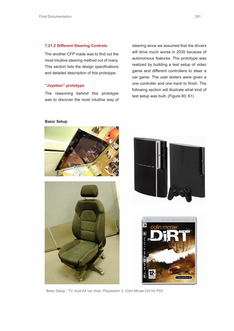
Final Documentation 291
7.21.2 Different Steering Controls
The another CFP made was to find out the most intuitive steering method out of many. This section lists the design specifications and detailed description of this prototype.
“Joysteer” prototype
The reasoning behind this prototype was to discover the most intuitive way of
steering since we assumed that the drivers will drive much worse in 2035 because of autonomous features. The prototype was realized by building a test setup of video game and different controllers to steer a car game. The user testers were given a one controller and one track to finish. The following section will illustrate what kind of test setup was built. (Figure 60; 61)
Basic Setup
Basic Setup - TV, Audi A4 car chair, Playstation 3, Colin Mcrae Dirt for PS3

Final Documentation292

Final Documentation 293
Test Setup:Small joystick control (Figure 62)Large joystick control: Saitek Aviator PC (Figure 63)Thrustmaster Experience Racing Wheel with Pedals (Figure 64)Sponge (Figure 65)Duct Tape (Figure 66)Reboard
Racing Wheel
Sponge
Duct TapeLarge Joystick Control
Small Joystick Control

Final Documentation294
Joystick as a tilting controller setup
Sponge
Reboard
Joystick as tilting controler setup

Final Documentation 295
Joystick as a tilting controller
For using joystick as a tilting controller a sponge was cut and paired with a large joystick. Tester needs to put feet on top of reboard and use feet tilting to steer and manage speed. (Figure 66: Joystick as tilting controler setup)
Controllers Gas and Brake Steering
Small Joystick Buttons Analog control
Large Joystick Analog up & down Analog control
Large Joystick Buttons Analog control
Pedals Buttons Left & Right pedal control
Feet tilting Analog up & down Analog control

Final Documentation296
Fall quarter was primarily used to gain more knowledge about the task we were given. We used the time to benchmark related industries and tested prototypes mainly based on our assumptions.During fall quarter we tested different ways of steering and discovered that the steering wheel was still the best way to steer.
In the beginning of the winter period we have already had understanding of the problem, future assumptions, user and the technology that might be available in the future. We had a meeting with our corporate partners in January and by then we had entire picture of what was expected from us to deliver and what might be our final goal.
Also, we tested different activities in the car and realized that the size of the vehicle was the only boundary we would face when it came to utilizing the time in the car. Space in the car was limited and making the interior of the car suited for different activities was our biggest challenge.
In addition, we tested the transition between autonomous and manual driving. In order for the driver to be confident in car’s ability to steer itself and to know that the transition of control has been made, there has to be a whole sequence of clues and reassurances. Because of its complexity, after winter period, transition from autonomous and manual driving still remained a problem that we needed to research more.
7.22 Needfinding7.22.1 Trip to GermanyAfter Christmas break, the team got an opportunity to visit Germany and had the first meet with corporate partners from Audi, which was the main purpose of this trip. Since we already traveled to Munich, we also decided to drop in BMW Museum and BMW Welt, as well as Audi Museum. In addition to previous, we also got an opportunity to visit University of Munich and see their automobile laboratory and jet engine laboratory. The trip itself was genuinely hectic but also highly educational. Travel plan for our travel can be found in Appendix.
List of our targets in chronological order:1. BMW Welt2. BMW Museum3. Audi Museum (Figure 68)4. 1st Meeting with Audi contacts Lorenz Bohrer and Tilo Koch5. Audi Factory Tour6. 2nd Meeting with Audi contacts Lorenz Bohrer and Ulrich Mueller7. University of Munich, Vehicle Laboratory8. University of Munich, Jet Engine Laboratory
Key notes• OLED technology is going to spread in
car interior design• We should narrow down our scope• Audi’s formula for successful products
is sophistication, sportiness and progressiveness
• 1/3 of people get “simulation sickness”
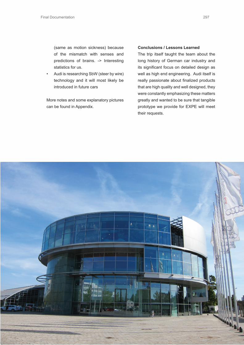
Final Documentation 297
(same as motion sickness) because of the mismatch with senses and predictions of brains. -> Interesting statistics for us.
• Audi is researching SbW (steer by wire) technology and it will most likely be introduced in future cars
More notes and some explanatory pictures can be found in Appendix.
Conclusions / Lessons LearnedThe trip itself taught the team about the long history of German car industry and its significant focus on detailed design as well as high end engineering. Audi itself is really passionate about finalized products that are high quality and well designed, they were constantly emphasizing these matters greatly and wanted to be sure that tangible prototype we provide for EXPE will meet their requests.

Final Documentation298
7.22.2 Geneva Trip
Geneva car show (Figure 69), as one of the biggest car shows in the world, annually attracts the most famous car manufacturers to present brand new car models and concepts. Many of them have their world premiere there. It was a unique opportunity for us to see what the current and future trends in car industry were, to speak with professionals from the field, to observe design of the cars, and to locate visual elements that make a car looks “futuristic”.
Observations• Electrical cars are a reality. Every major
car manufacturer already provides an electric vehicle.
• Car manufacturers are constantly expanding the number of models they offer. Many manufacturers already have small vehicles (size of Toyota IQ,
Smart for two, Aston Martin Cygnet...) or they offer slightly bigger versions for four passengers.(Fiat 500, Opel Adam, Citroen DS1...), but also there are many vehicles between already established classes, like small SUV’s, Expensive sport cars hatchbacks (Ferrari FF, Aston Martin Rapide...) or even cars between motorcycles and passenger vehicles. (Renault Twizy, Toyota Iroad...)
• Current trend in the visual appearance of the cars is to have lines which are “braking” the surfaces in not so logical manner. Lines are not parallel to the ground any more, but they flow freely on the surface of the car.
• LED lights and glowing lines in headlights are common
• Even small, compact vehicles tend to look aggressive
Geneva Car Show

Final Documentation 299
Conclusions / Lessons Learned• Combination of colored LED lights
(usually light blue), transparent materials and playful mixture of different lines and patterns on the chassis of the car make the car look more dynamic and “futuristic”
• There are not many changes in the car interiors. Mainly, changes are related with introducing new technology, like touch screens.
• It is possible that in the future there will be more vehicles for one or two persons.
7.22.3 Dashboard QuestionnaireWith dashboard questionnaire we wanted to explore how aware of different indicators that are on a dashboard the users actually are. Rationale behind this was to see what information is actually valuable for driver to have when he is using a car. We had two different kinds of questionnaires (Figure 70 and Figure 71). In 1 questionnaire we asked drivers to identify what each logo was for on on the dashboard. In questionnaire 2 we asked drivers to arrange the meters in order based on their opinions from the most useful to the least useful.
Results• Halves of the logos on questionnaire 1
were not known or wrongly interpreted by 12 testers.
• Indicators like engine oil temperature, ABS, cruise control, airbag, check engine light, battery level, were not always needed.
• Motor temperature, oil temperature, and battery life were considered the least important indicators in questionnaire 2 by 16 testers.
Conclusions / Lessons LearnedCompared with dashboards in 20 years ago, dashboard is more simple, showing less information. We may get rid of dashboard and only show the most important indicators on augmented reality windshield. Drivers can choose customized information that they want to see. Some information like fuel condition and turning lights is only shown when needed. This way we get more cabin space. This area may be utilized for working space.
1.
2.
3.
4.
5.
6.
Dashboad Questionaires
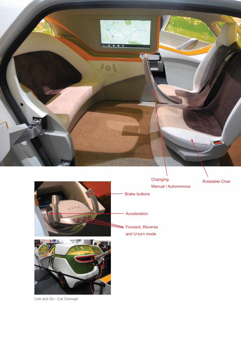
Final Documentation300
Brake buttons
Rotatable ChairChanging Manual / Autonomous
Acceleration
Forward, Reverseand U-turn mode
Link and Go - Car Concept

Final Documentation 301
Rotatable Chair
7.23 Benchmarking7.23.1 Akka Car ConceptAmong other cars at the Geneva car show, there was one car which focuses on the same issue as we do. It was a working prototype of an autonomous car, done by Akka Technologies in collaboration with other companies that provide software.The concept is called Link and Go (Figure 72) and it offers both manual and autonomous driving experience.
ObservationsOutlook of the car:• Car doesn’t look sporty or aggressive.
It is mainly a functional vehicle which is for convenience and not for pleasure.
• It is slightly taller than normal cars. It provides more comfort and the sense of freedom.
• The whole car is larger and has more space in the interior.
• Back seat looks like a piece of furniture and the whole car looks more room like
Mode changing• Front seats are attached to each other
and are rotatable 360 degrees. Driver can turn the front seat entirely and socialize with people in the back.
• During the rotation of the seats, there is not enough place for legs.
• Changing between modes is done before the drive. There is no option for changing modes on the go. There is a display attached to the front seats where user can set up the mode.
Steering• Steering wheel is always visible,
but it doesn’t spin when the car is in autonomous mode.
• Acceleration and brake pedals are removed. Acceleration is done by pulling handles behind the wheel and braking is done by pressing buttons with thumbs.
• Steering wheel moves closer to the dashboard when not in use.
• When in driving mode, driver needs to manually pull the steering wheel closer, in order to drive.
• When driving, the seat can be locked.• Drivers seat is really not ergonomically
designed for comfortable driving, but for multifunctionality and changing of the modes.
Performance• The car is a working prototype. It has
sensors in the front and a big sensor on the roof of the car.
• The car is designed for city use. It has a maximum speed of 50 km/h when in autonomous mode and 120 when driven manually.
• Car is meant for the year 2025 because of the legal issues.

Final Documentation302
7.24 Dark Horse PrototypesDark Horse prototype is the term we use to describe a prototype which reflects our most radical and risky ideas. It presents a leap of fate, something that might work and maybe can be implemented in the final concept or as the concept itself. In this exercise we were encouraged to think outside of the box and this was our last chance to experiment and to test unconventional ideas before we focus on something which will eventually be our final concept.
Because of the lack of time caused by our trip to Germany, we had limited time to develop highly functional prototype, basically we only had only one more sophisticated prototype. In addition, we decided to make a few of rapid prototypes of our ideas and to present those to users for some feedback and further inspiration. In the following paragraphs we will explain these prototypes briefly.
7.24.1 Dark Horse Prototype -
“Reconfiguro”The dark horse prototype tested whether the users of autonomous vehicles would value the concept of a reconfigurable interior space. A reconfigurable space would allow the users to pick and place the objects and furniture that would be an appropriate fit for the activity they would do in the vehicle. This prototype also determined what level of control the users would want to have over the reconfigurable space.
SetupTo create a realistic experience for this prototype, it was pertinent for the users to feel what it would be like to reconfigure the interior space from the outside and then perform various activities within the space. The team rented a U-Haul moving van to replicate the autonomous driving experience, as show in Figure 73. The can already had a partition between the front and backspaces so the user had no visuals of the front and the driver. The objects that were available for the user

Final Documentation 303
to configure the van’s back interior space included two chairs, an inflatable bed with pillows, a low-rise nightstand, a high-rise desk, a TV projector, a desk lamp, a deck of cards, drinks, and magazines. The TV projector was used in conjunction with a laptop computer to display TV shows on the van’s partition screen (if the TV projector was selected in the interface) or a front-view driving visual (if the projector was not selected), as shown in Figure 74. The user interacted with a tablet interface
prior to getting into the van to configure the space to give them a realistic experience of what it would feel like to control the cabin space remotely from anywhere. The vehicle was also equipped with speakers not only to play the audio from the TV shows and music, but to amplify a text-to-speech application to imitate a robotic car voice. The text-to-speech voice was used to communicate with user of their travel updates, ask the user specific questions, and to respond to any requests from the user.
Reconfiguro Setup

Final Documentation304
Control InterfacesThree different interfaces were tested within this experience to determine what level of control the users would want to have over the reconfigure space. The first interface was a Java “drag and drop” application (shown in Figure 75), which the user could have full control over where and in what orientation the objects, could be placed in the interior. The drag and drop application was designed to portray the objects in a proportionally realistic manner relative to the size of the van’s interior space which allowed the user a better perception of what could really fit in such a space. The code for the java application can be found in Section 9.8.2 APPENDIX.
The second interface was a “parameter-based” application (shown in Figure 76) in which the user would answer specific questions pertaining to the parameters of the activity or drive. The user would answer questions such as “how many passengers will be riding”, “how long will you be riding”, and “Set car for: (relax, sleeping, socializing, etc.)”. Unlike the drag and drop interface, this parameter-based application gives less control to the user in the type of configure that is possible within the interior space. The slides for this interface can be seen in APPENDIXSection 9.8.3.
Control Interface

Final Documentation 305
The third interface that was tested was based on the concept of a “lifestyle sync” application in which the autonomous vehicle knows the users schedule for the day and rearranges the space based on what kind of things the user will be doing throughout the day. The vehicle also talked to the user and intuitively knows if the user needed something specific. For example, if the user just went to the get a Starbuck’s coffee but there is no cup holder in the previous configuration. The vehicle will know and prompt the user if he or she needs a cup holder. With lifestyle syncing, the vehicle would train and learn from what the user needs, requests, and actually does to be able to configure the vehicle in the most optimal way.
The “drag and drop” and “parameter-based” interfaces were presented on a small tablet device to give the user a realistic experience of what it would be like to configure the vehicle’s space remotely from anywhere. The “lifestyle syncing” interface was given to the user as a survey to determine what their schedule would be, and then the space was configured for those activities.
Control Interface - Parameter Based

Final Documentation306
Testing ProcedureThe testing was performed on campus with different stops locations around campus:1. Starbucks to pick up a cup of coffee2. Work to pick some books3. Trip to pick up a friend
Figure 77 portrays the different experience flows for each of the interface interactions and demonstrates the behind the scenes procedure to reconfigure the space. Experience flow 1 and 2 correspond to the drag/drop and parameter’s based interface. The user was given the story about that they just received an autonomous car and they were going on three different stops around town (stops were performed on campus). The user dragged/dropped where they wanted the furniture to be placed within the cabin space or answered questions pertaining to the parameters of the activity and drive. Once the space was configured accordingly, the user hopped in the back and proceeded to the first stop, a 5-minute journey. The user picked up a snack or coffee and right before heading back to the van, they reconfigured the space to their needs or desires. The next stop was a 20-minute journey and the user performed similar tasks as during the first stop. The last stop consisted of picking up a friend and socializing.
Experience flow 3 corresponded to the “lifesync” application. The van knew the user’s schedule and preferences and made an educated guess at how they wanted the cabin space to be configured. The flow 3
was very similar to flow 1 and 2 except that the user did not reconfigure the space. Another additional feature within flow 3 was the ability to communicate with the van by asking specific questions or requests and the car would respond.
The behind the scenes action of how the whole experience flow worked was very important. Two of the team members operated the van environment; one person was driving while the other person was operating all the internal features. The other member followed the van on the routes with all furniture objects that were not in the cabin space. Once the van made a stop for the user and the user went off to perform their tasks, the entire team reconfigured the cabin, swapping objects from car to van.

Final Documentation 307
Experience Flow 1 and 2
User selects configuration from the tablet interface
User reaches car
and starts with short
5 min journey to
grocery store
User reaches stop 1 and goes shopping.
Uses tablet interface
to re-change configuration.
Long Journey to
work started based on the configuration
chosen.
After work, car
reconfigured for two people and socializ-
ing with a friend.
User comesIntroduction story
marrated. Schedule given.
Experience Flow 3
User reaches car
and starts with short 5 min journey to
grocery store
Users go shopping and return to find
space reconfigured for them.
Long Journey to
work started. Car
prompts user for things they would
like to change.
Changes are made by making a quick
stop.
After work, car
reconfigured for two people and socializ-
ing with a friend.
Car still prompts for comfort with current
configuration and desired changes.
User answers preference survey
User comesIntroduction story
marrated. Schedule given.
Behind the scenes
Two members of
theam in the van.
One member
follows in another
car with spare
furniture.
Cabin space is
reconfigured based on what user wants
and team is in
driving position
One team member
follows in van and helps in changes
on the go.
Cabin space reconfigured based on what user wants
and team is in driving position.
Two team members ready near the van
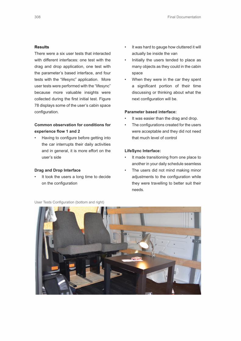
Final Documentation308
ResultsThere were a six user tests that interacted with different interfaces: one test with the drag and drop application, one test with the parameter’s based interface, and four tests with the “lifesync” application. More user tests were performed with the “lifesync” because more valuable insights were collected during the first initial test. Figure 78 displays some of the user’s cabin space configuration.
Common observation for conditions for experience flow 1 and 2 • Having to configure before getting into
the car interrupts their daily activities and in general, it is more effort on the user’s side
Drag and Drop Interface• It took the users a long time to decide
on the configuration
• It was hard to gauge how cluttered it will actually be inside the van
• Initially the users tended to place as many objects as they could in the cabin space
• When they were in the car they spent a significant portion of their time discussing or thinking about what the next configuration will be.
Parameter based interface:• It was easier than the drag and drop.• The configurations created for the users
were acceptable and they did not need that much level of control
LifeSync Interface:• It made transitioning from one place to
another in your daily schedule seamless• The users did not mind making minor
adjustments to the configuration while they were travelling to better suit their needs.
User Tests Configuration (bottom and right)

Final Documentation 309
• The users liked the fact that the car anticipated their needs and gave suggestions for changes to the configuration that the user might desire
General Experience Observations:• While relaxing, the users did not always
want to be lying down completely, would prefer something like a reclining chair. Users reposition themselves a lot in the cabin space.
• Just the front projection of driving is not enough to comfort the users and make them feel safe
• Maintaining visuals not just for situational awareness and safety but also for pleasure is important
• People get used to voice commands while interacting with the car very quickly and if it stops talking to them then they feel that something is wrong. There is an emotional connection that is developed with the car when the car talks to the users.
• Facing each other was most conducive for work meetings and socializing. Having them sit right next to each other can be useful for multimedia or for romancing.
• The person that gets picked up views the other person who was riding the autonomous car before as the owner. - (In one instance, when the car asked a question to the users and they replied with different opinions then the person who owns the car gets priority in group dynamic. In the second instance, the friend did not really interact with the car as much as the owner, as they are under the assumption that they owner knows better how to interact with their car.)
• Rider became embarrassed when the car asked something that revealed personal information.
• When a user was riding sideways, their body was turned slightly towards the front.

Final Documentation310
• If the car did not establish rapport early into the ride they felt less comfortable in speaking with the car. People got really comfortable very quickly after this.
• Since it does not feel like a car anymore, you need more accessories like trash cans, outlets, wifi.
• While talking to the car, the users want to humanize it as much as possible.
• Things kept falling off the table. Having just a fixed cup holder makes it constrained a lot.
• Car not interrupting the conversation of a group or knowing when to interrupt the conversation. It is essentially like another human that must follow all the social etiquettes.
• Car user confidentiality - what information is revealed in front of the user’s friends and what is not.
• Changing configuration when the car has stopped was better. So there is a need to change configuration safely when the car is moving.
• The users forgot that they were in the back of the van and when they saw other cars in the projection, they suddenly realized that they were also in a car and the projection was in fact distracting to the main activity in which they were engrossed.
ConclusionPeople value the benefits of being able to optimize the cabin space for different activities but they would like to do so in the least amount of effort and intrusion in their daily lives. From the insights collected
from the darkhorse prototype, the team wanted to focus on the aspects of mobility and flexibility within a smart cabin space design, and concluded that within the cabin, the chair is an important factor that affects this design space. One possible solution was to design a chair that senses whether the user is falling asleep or if they wanted to rotate and sit in a different orientation and it just does that without the user inputting any specific commands. So is it possible to sense a user’s intentions and adapt the chair’s position based on the user’s body movements while not intruding in the user’s activities?
7.24.2 Dark Horse Prototype - “SbW
Imitation”Night before leaving to Germany, we wanted to test with a quick prototype if it is possible to steer in non-ordinary positions, for example sideways or back towards front. (Figure 79)This prototype was based on our assumption that future autopiloted cars will be aware of the surroundings so that optimal driving position is not necessarily required for safe driving.
To see if driving is actually possible in various positions, we could maybe place the steering elsewhere in the car and this way acquire more freedom in cabin design. We wanted to also test how does it feel to have contradiction between expected vehicle movement and the actual vehicle movement.
After visiting Audi, they kindly suggested us to focus on some other factors inside the

Final Documentation 311
cabin. They also told us that they already have an own laboratory focusing on this so called Steer-by-Wire -technology. The reason they are studying this is mostly because it allows the extra freedom in dashboard are and also because in future electric cars are mostly done with this technology. This is because it reduces car weight and the car is already eclectic and would not function at all without electricity? This sort of digital technology replaced analog speedometer in late 1970s and it is going to eventually replace the analog steering.
Setup• Skype call between iPhone and iPad ->
quick analog setup for screen/camera solution
• iPad was also used as a steering wheel• One person was pushing and steering
the vehicle according the drivers gestures
• Before iterating setup any further we quickly tested steering sideways and back towards front
Iphone with camera, giving a vision forward Ipad as a wheel and screen

Final Documentation312
Observations• Vehicle can be steered in non-ordinary
positions in slow velocities without difficulties to adapt
• Minor crashes were caused by rough setup since the external person steering cannot react right after the driver has given the input
• There is also a little delay between the phone and iPad which also makes steering a little difficult
Conclusions / Lessons LearnedWe can assume that the future electric cars are going to use this SbW-technology since it already under a lot of research at Audi. The delay issue can also be solved with more sophisticated technology. To test functionality of steering through screens in non-ordinary positions needs to be tested in higher velocities before validating that it could be done. If our project is heading into this direction we need to test this.
7.24.3 Dark Horse Prototype - “Sleeping
Positions”Since almost everyone would like to sleep in the car if it would be possible, the team wanted to build various sleeping setups to imitate different possibilities to do so. Two assumptions exists:
1. Driver sleeps in a comfortable position so that he/she can enjoy complete relaxation. However, in this situation, it is hard for the car to wake up the driver in a relatively short time.
“ everyone would like to sleep in the car if it would be possible”
2. Driver sleeps in a relatively uncomfortable position so that he/she can enjoy a nap, and the car is able to wake the driver up in a relatively short time.
Sleeping in first generation autonomous cars, which are going to be introduced within 10 year, sleeping is not most likely going to be possible since reorientation from sleep takes too much time (about 30 seconds) and and early autonomous cars have to be able to give the controls for the driver in some situations. This is not a problem in later generation autonomous cars, where our target year 2035 is situated. In 2035, infrastructure and car’s autonomous features are advanced enough to allow sleeping in the driver’s seat.
Setup One (Figure 80)Using the first assumption as a guideline, the team came up with sleeping position sideways to direction of movement. Driver seat turns 90 degrees to the right from the face forward orientated position and the chair transforms into a bed. This idea derives from the fact that beds are positioned like this in trains to prevent possible motion sickness.
Setup Two (Figure 80)Under our second assumption, we observed that if it is possible for a person to fall asleep

Final Documentation 313
in straight sitting position as long as the user’s head is supported so that it does not fall. Therefore, we made a head holder out of pillows for the user to see if it is possible to sleep like this or not.
Setup Three (Figure 80)Third setup included a device that has a flat and soft surface to support the head and the same kind of chest support the upper body (Figure Sleeping Positions 3). This setup got its idea from the way people sleep in airplanes. Since the inclination of the seats are so minor, sleeping is difficult in a regular way. In this kind of situation people are forced to figure out more ways to sleep comfortably. In airplanes you can see people sleeping on the table in front of them leaning on their hands

Final Documentation314
ObservationsThe first setup is not much different from the regular sleeping position. Issue with this setup is to have the required space in cars cabin. Width of the car is not enough for this kind of setup so it is impossible to sleep sideways.
In the second test setup the users neck gets tired really quick since the weight of the head is too much to support if the neck muscles are operating because of sleeping. This setup is not good for even a quick nap since it causes ache for the user.
In the third sleeping works actually quite well if the support is just correct for the user. Spine is more relaxed as well as neck. User’s chest gets a little too much pressure since the body weight is mostly on chest and breathing causes chest movement and increases load on the chest.
Conclusion / Lessons LearnedReplacing the traditional sleeping position in rational way is not possible since we would have to compensate with users ergonomics and we are not willing to do so. Sleeping in the drivers seat has to be done somewhat the same way it is done in the seat next to the driver.
7.24.4 Dark Horse Prototype - “ AR
Imitation”
Because augmented reality technology (AR) is going be available in future and various applications are going to be possible with that, we wanted see if it is possible to imitate it.
SetupWe tried to draw augmented information on a glass of a protection helmet. Details we drew on the glass was mainly driving related, such as speedometer, road and navigation information. (Figure 81)
Conclusion / Lessons LearnedWe quickly immediately realized that this technology is almost impossible to imitate like like this since the eye has to focus on the details drawn on the glass and therefore blurring environment. Therefore this is not useful to imitate augmented reality like this.
Top - Protection helmet split Bottom - Transparent Foil

Final Documentation 315
Top - Protection helmet split Bottom - Transparent Foil
7.24.5 Dark Horse Prototype -
“Disappearing Steering Wheel”
With this prototype we wanted to test one of our ideas for transition between, what we called, manual and autonomous mode. Idea was to create a mechanism that will hide the steering wheel, so the user can utilize the dashboard space for some other activity, when he/she is not required to steer. The whole purpose of this prototype was to visualize in a tangible way what we had in mind and then, to use that prototype to inspire conversation or to get some ideas.
SetupThis prototype is one of many “quick and dirty” prototypes. We made a cardboard steering wheel that we attached to a cardboard table (which imitates the dashboard - Figure 82) We made two slices in the table and used the tape as hinges in order to make the board rotatable.
Observations• When flipped, steering wheel requires a
lot of space below the dashboard.• We could imagine that the cuts in the
table would give the interior very cheap
outlook.• The cuts wouldn’t be very convenient,
especially when the table is used for eating.
Conclusions / Lessons LearnedAlthough the prototype was rough we quickly realized that this solution for making utilizing the dashboard was not probably the best solution. This construction gave very mechanical outlook and caused more problems than it has solved. We realized that we need more simple and more sophisticated solution to this problem.

Final Documentation316
in some convenient place. Places suggested:
• Cars roof• On the bench next to drivers seat• In personal bag or purse
What would the user do with detachable steering wheel?• Use the steering wheel as control device
in leisure mode for car’s infotainment system
• Steer the car from outside like a remotely controllable car
• Wheel could have a picture of the car from bird view like a computer game
What other functions detachable steering wheel makes possible?• Steering wheel could be used as a
personal tablet• Augmented reality in the wheel, like
personal tablet but with more futuristic technology
• Steering wheel could be a key as well that could lock the car and prevent its usage if the steering wheel is not near
7.24.6 Dark Horse Prototype -
“Magneto”
Idea behind Magneto prototype was to test what users will do with the steering wheel if it was possible to attach anywhere on the dashboard. Prototype acted mainly as a conversation starter.
SetupWe made a dashboard made out of cardboard with metal underneath, and steering wheel of plywood with a magnet in order to fake the steering wheel mounting. (Figure 83)Test setup was organised on a table and mood was set by explaining that there is two modes of driving: manual mode where you drive yourself and autonomous mode, where the car drives itself. During this we conversed with the tester and tried to collect valuable feedback from it. (Figure 84)
Discussion Key NotesWhere would the user put the steering wheel?• User would put the steering wheel

Final Documentation 317
the car Conclusions / Lessons LearnedUser testing is a fundamental way of getting feedback and ideas from prototypes. Prototype does not have to be that sophisticated to open a conversation and communicate the idea. Here we learned that building and testing more is learning more. Ideas generated by users was listed

Final Documentation318
7.25 Funky PrototypesFunky prototype is a term used in ME310 for an approximation prototype of the full system without making a costly commitment to any one configuration, technology, or geometry. This prototype is still a low-commitment, rapidly assembled, concept prototype that allows for objective evaluation and testing.
7.25.1 Funky Prototype
”Anticipatory Chair”
The team wanted to explore the concept of facilitating seamless transitions between activities by having a chair that senses the changes in your body position and language & moves to accommodate those changes. The hope is to create a feeling of more mobility by removing the need to make
chair adjustments before continuing on to a different activity. This prototype was trying to determine if users value this anticipatory system and if it could be achieved by using force sensors.
Test SetupUsers were asked to perform the list of activities taped to the dashboard in any order and at whatever interval they wanted. The list of activities included driving, trying to take a nap, reaching for your backpack in the backseat, watching TV, texting/ reading a magazine, and talking to your passenger. (Figure 85) User activities displays the activities being performed from an actual

Final Documentation 319
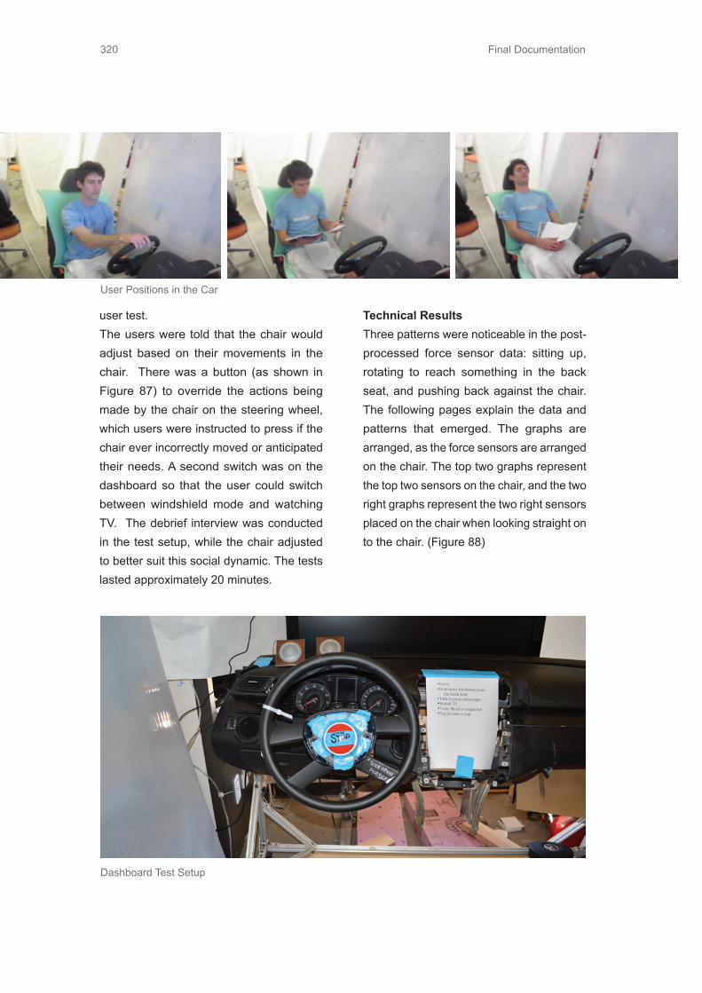
Final Documentation320
user test.The users were told that the chair would adjust based on their movements in the chair. There was a button (as shown in Figure 87) to override the actions being made by the chair on the steering wheel, which users were instructed to press if the chair ever incorrectly moved or anticipated their needs. A second switch was on the dashboard so that the user could switch between windshield mode and watching TV. The debrief interview was conducted in the test setup, while the chair adjusted to better suit this social dynamic. The tests lasted approximately 20 minutes.
Technical ResultsThree patterns were noticeable in the post-processed force sensor data: sitting up, rotating to reach something in the back seat, and pushing back against the chair. The following pages explain the data and patterns that emerged. The graphs are arranged, as the force sensors are arranged on the chair. The top two graphs represent the top two sensors on the chair, and the two right graphs represent the two right sensors placed on the chair when looking straight on to the chair. (Figure 88)
User Positions in the Car
Dashboard Test Setup

Final Documentation 321
Force Sensors
Force Sensors on the Chair

Final Documentation322
Observations• Users would pull at the wheel slightly
when they wanted to move into driving position.
• Users would begin to push back against the chair if the chair moves in a direction that the user did not want.
• Rotating the chair to reach a backpack was useful only when the backpack was out of reach. Otherwise the chair did not react fast enough to be helpful.
• Comfortable angles of recline differed for each user.
ResultsThe team discovered that force sensors seem like a fairly feasible way to identify simple user intentions like pushing back on the chair to recline, but a higher density of sensors in conjunction with additional types of sensors will be needed in order to better distinguish between more complex intentions like the desire to socialize with
Force Pattern 1: Sitting Up (from reclined position to driving position)These graph (Figure 89) demonstrates leaning up from the seat back and waiting for the seat to move into driving position. When the person sits up, the two upper sensors read no force since their back is not touching the chair. Once the seat starts touching person’s back, the two lower sensors become active. For the seat cushion, as the person sits up from a reclined position all their weight is then shown in the seat cushion force sensors, which is why one can see an increase in all four bottom sensors to a steady state value.
passengers. In general, users had a positive experience with this anticipatory sensing chair prototype when the chair matched their intentions. In instances where the chair was initially incorrect in its anticipatory action, users still did not want to regain manual control over the chair and felt it made their transitions easier.
Seat Back Data
Sitting up = 0 force read
Seat hitting lower back as chair raises
into driving position = INCREASE in force

Final Documentation 323
Force Pattern 2: Rotating (to reach for something in the back seat)These graph (Figure 90) demonstrate rotating / leaning towards the back to grab something. At the red transition mark, the entire top right side sensors goes to zero while T1 (lower left sensor, the direction the user was leaning) increases. After the
red mark transition, the data shows a lot of movement shifting. Since there were not enough sensors to capture the entire chair, the variation makes it hard to distinguish what exactly is going on. Conclusion, need to increase density of sensors among the chair to help filter out small movements shifts that are unintentional.
Seat Cusion Data
Seat Back Data
Top right sensor = 0 force
Sitting up = INCREASE in force
Lower left sensoras user rotates
in that direction = INCREASE in force.
Force Pattern 1
Force Pattern 2

Final Documentation324
Force Pattern 3: Pushing Back (to recline)These graph (Figure 3) demonstrate pushing back on the seat. The top seat back sensors (T2 and T4) increase as the user pushes against the seat back. The top seat cushion sensors (B2 and B4) decrease, while the lower seat cushion sensors (B1 and B3) should slightly increase. This increase is seen in B3, but because of the user’s position in the chair B1 did not detect this increase.
Rotating to other side = DECREASE in force on all right sensors
Rotating to this side = INCREASE
in force
Pushing on seat back = INCREASE
in force
Seat Back Data
Seat Cusion Data

Final Documentation 325
Pushing on seat back = DECREASE
in force
Pushing on seat back = slight
INCREASE in force
Seat Cusion Data
7.25.2 Funky Prototype
”What should I do”
The team wanted to find out gestures and subconscious movements users performed within the cabin space to validate whether people perform unintentional gestures in unfamiliar situations. This prototype was suppose to encourage innovative thinking and offer us new and different ideas for triggering these two modes. The team believed that this prototype might uncover intuitive gestures that people do when they oriented themselves into a driving or leisure position.
Test SetupThe concept of the prototype was to design a dashboard with a steering wheel that could disappear by flipping the dashboard. It consisted of a car seat and a dashboard that had a steering wheel on one side and an original dashboard on the other side. The windshield was imitated with two different
sceneries, one with a dull road and one with fun-to-drive road. All test situations were filmed with a camera to later observe the user’s reactions and body language.(Figure)
The team tested the prototype in several different locations including Design Factory, Administration Building, and Motonet (a local hardware retailer store).
The test started with an explanation of the situation the user was in. We ended the explanation by suggesting the user to try to summon the steering wheel. After the user got the wheel to appear, we reset the scenario and asked the user to retract the steering wheel. In our test there was no right gesture for summoning the wheel, so we did not a have a locked gesture for summoning the steering wheel. The test process is explained in the picture on the next page.
Force Pattern 3
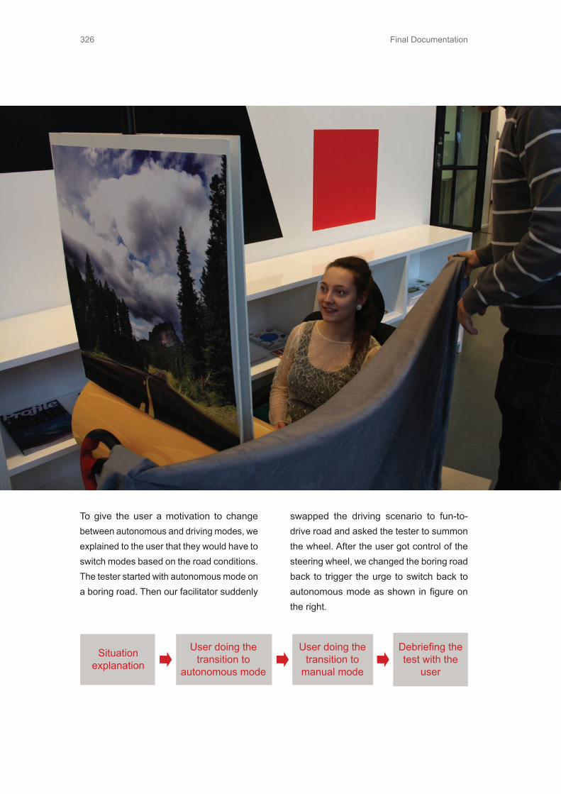
Final Documentation326
Situation explanation
User doing the transition to
autonomous mode
User doing the transition to
manual mode
Debriefing the test with the
user
To give the user a motivation to change between autonomous and driving modes, we explained to the user that they would have to switch modes based on the road conditions. The tester started with autonomous mode on a boring road. Then our facilitator suddenly
swapped the driving scenario to fun-to-drive road and asked the tester to summon the wheel. After the user got control of the steering wheel, we changed the boring road back to trigger the urge to switch back to autonomous mode as shown in figure on the right.

Final Documentation 327
Autonomous mode Autonomous mode
Autonomous mode
Manual mode
Manual mode Manual mode
Boringroad
Boringroad
Fun road
Fun road
Trigger for Transition
Trigger for Transition
Test ResultsWe defined inputs that the users gave us as suggestions and categorized them into different groups. There were 11 testers with suggestions pertaining to both driving and autonomous mode. We have 44 suggestions collected in the table below. To ease the comparison between different suggestions, the data is collected into graph that can also be seen in (Figure 95).
These were mainly suggestions that users gave us knowingly. Voice recognition and
regular buttons were most commonly suggested. Most of the hand gesture suggestions were performed subconsciously. This was what we were looking for, but as can be seen from test dat, it was not a common suggestion. Although there was hand gestures at some point, it was never the first suggestion.
Observations• Testers were afraid to fail, they did not
go wild on ideas as we thought they would.

Final Documentation328
30
25
Touch VoiceG estureE yeRecognition
Brain Waves
20
15
10
5
0
Amount in Total
1st “Gesture”Suggestion Amount
2nd “Gesture”Suggestion Amount
3rd “Gesture”Suggestion Amount
4th “Gesture”Suggestion Amount
5th “Gesture”Suggestion Amount
Suggestion Genre Categories Touch Voice Gesture Eye
Rec.Brain Waves
Suggestions in Total
Amount in Total 23 11 5 3 2 44
1st “Gesture”Suggestion Amount
14 2 2 1 0 19
2nd “Gesture”Suggestion Amount
2 4 2 1 2 11
3rd “Gesture”Suggestion Amount
3 4 0 1 0 8
4th “Gesture”Suggestion Amount
2 1 1 0 0 4
5th “Gesture”Suggestion Amount
2 0 0 0 0 2

Final Documentation 329
• If the first suggestion they gave was not “right”, they thought quite a while before another try.
• Some users lifted their hands to imitate driving when they realized it is a mock up of a car interior.
• People from Design Factory are a lot more open to wild ideas and it is easier to get those from them than people out of the university area.
• It seemed to be really hard for users to position oneself far in the future.
• Users tended to suggest ways that were already working functions for them. For example one user was praising voice control since he had had so good experiences with his voice controllable GPS.
Debrief Feedback• One tester would like to have some
indication when the controls are under his control, other than only steering wheel appearing.
• Users can be thought any kind of behavior, for example calling to service lines every time when there is a problem is a learned habit from work for example. There is always someone else responsible for matters that you are not responsible for.
• Test setup was too humiliating, tester got frustrated when the suggestion he was sure was right did not work.
• Voice browsing through menus are too complicated and slow. Most likely the voice commands will not be like that, more like direct commands to do different actions.
Conclusions / Lessons Learned
Voice recognition and touchable buttons seemed to still be the most intuitive way for users to transit from autonomous to driving mode. One possible solution is to have a combination of commands that map to different user interaction. Another possible solution is hand gesture that initiate various modes. If the user does not have hands on the steering wheel, the car will clearly increase autonomous functionality and if hands are on the steering wheel, the car will decrease autonomous feeling.We also realized that especially in car world, the prototype has to be sophisticated enough to communicate well with the tester, otherwise it is really hard to get valuable feedback.
Testing with users outside the university environment is a whole other matter. The whole test setup needs to be very well planed. In Design Factory it does not really matter, since people are used to test different kinds of prototypes, but normal citizens who just want to take care of their daily business is a different matter. In the future we have to be really careful that we do not confuse testers with unclear test setup.
Since the year 2035 is far in the future, it is difficult for normal people to comprehend. We have been living in the year 2035 for 4 months and the futuristic world is really familiar to us. But for random people in a store it is almost impossible to step into future just like that. For future testing we should not include the futuristic aspect too much, it seemed to just confuse the user.

Final Documentation330
7.26 Functional System Prototypes• How well can people adapt to this new
chair interaction?• Are gestures an appropriate method to
initiate transition between driving and
autonomous mode?
Functional System prototype is a term used for ME310 prototype that is still a bit crude, and obviously assembled from off-the-shelf parts; however, this time decisions ontechnical implementation are done with increased sophistication.
7.26.1 Functional Sytem Prototype
”Anticipatory System”
Based on a successful funky prototype, the team decided to move forward and test the entire functional system with full integration of the steering wheel and Chair Sense being implemented in a closed loop. The concept being tested is one, which facilitates effortless transitions between activities by sensing the intentions of the user through intuitive body command movements and intentional mode initiating gestures.
Prototype DescriptionThe funky prototype was developed further to include closed loop commands for the chair motions based on inputs from the force sensors on the chair and gestures being recognized from the Microsoft Kinect camera. Another addition to the prototype is a functional steering mechanism, which emerges from the dashboard only when
in the driving mode and is hidden in autonomous modes as seen in Figures 96 and 97. Complete functional system prototype setup 1 & 2. The steering wheel is also hooked up to a driving simulator for users to get the experience of driving and transitioning between autonomous and driving mode. A projector has been used to mock up the windshield in front of the user, as they would experience in a real vehicle. The team also verified that the chair twist/rotational motions work with a person sitting in the chair.
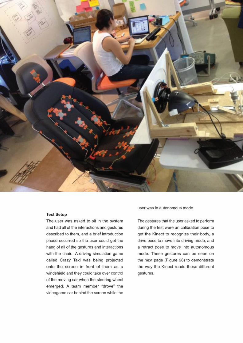
Final Documentation 331
Test SetupThe user was asked to sit in the system and had all of the interactions and gestures described to them, and a brief introduction phase occurred so the user could get the hang of all of the gestures and interactions with the chair. A driving simulation game called Crazy Taxi was being projected onto the screen in front of them as a windshield and they could take over control of the moving car when the steering wheel emerged. A team member “drove” the videogame car behind the screen while the
user was in autonomous mode.
The gestures that the user asked to perform during the test were an calibration pose to get the Kinect to recognize their body, a drive pose to move into driving mode, and a retract pose to move into autonomous mode. These gestures can be seen on the next page (Figure 98) to demonstrate the way the Kinect reads these different gestures.

Final Documentation332
The user also tried to utilize the chair sense feature. The team would adjust the placement of the force sensors in order to ensure a better data output and to ensure that the amount of pressure they needed to exert on the chair to make it incline or decline was not too much or to sensitive. The modes they could experience were driving mode and autonomous mode. Driving mode entailed having the chair move closer to the dashboard into an upright driving position and having the steering wheel emerge. Autonomous mode entailed having the chair move away from the dashboard and recline into a more comfortable and relaxed seat position, as well as having the steering wheel retract and be hidden from the user’s view and out of their reach. Once the users were familiar with all of the interactions with the system, the team let them just transition through the activities and modes they as they pleased.
ResultsChair Sense interaction:• For tall or short people it was difficult to
use the interaction.• The force sensors were often not placed
correctly to ensure proper pressure distribution.
• Due to the angle of the Kinect, it was unable to capture their entire upper body so the Kinect could not understand their gestures.
• The responsiveness of the sensors was annoyingly sensitive
• The chair was oscillating around the position the user actually wanted to be
Calibrated Position
Drive Position
Retract Position
Gestures recognized by the Kinect software 1, 2, & 3

Final Documentation 333
in.• Pushing back against chair felt very
natural• There is a sandwich threshold, which
the user will get stuck in and be unable to push the chair back.
• If this threshold is met, users immediately want to turn off these smart features or get out of the chair.
• People are afraid of being crushed by the chair allowing to go past this sandwich threshold
Steering Mechanism Interaction:• People wanted to keep both hands on
the steering wheel, while signaling that they wanted to go into autonomous mode.
• Removing their hands from the wheel made them feel unsafe and felt awkward
Other Considerations:• Most users wanted a twist motion.• All users described several instances in
which they would want this exist, even in cars today
• Wished there was a way to lock & unlock chair sense
• Users wanted a way to tell the chair to stop in the position they wanted, in the event that it incorrectly reacts.
ConclusionsThe team concluded that the thresholds we set for the sensitivity of the chair must be dynamic and change as the chair position
changes. The data collection points also cannot be fixed to point on the chair, but rather use reference points from the user’s body. For instance, using pressure data where the chair touches just below the top of the user’s shoulder. That way height will not affect the data and chair’s responsiveness. Another important discovery was that gestures were triggered randomly just when a person was gesticulating. Therefore, we do not think gestures should be used as mode initiators. Instead, gestures could be used as a way of weeding out unintentional body movements as opposed to intentional body commands.
In general, people enjoyed the experience and concept. Specifically, they enjoyed moving from driving mode into autonomous mode as it meant the chair moved to a more relaxed position and the steering wheel went away. It made them feel free to not worry about driving anymore and instantly put them in a position that was more enticing.
7.26.2 Functional System Prototype -
“Buckle It Out”
• What is needed for effortless transition?• What kind of problems there are while
changing between autonomous and driving mode with a seatbelt switch?
The two design teams conducted different prototypes for the same purpose: to provide an easy trigger of autonomous mode and manual mode, and to test the transition between mode changes. Both teams decided to hide the steering wheel when in

Final Documentation334
autonomous mode, based on the rationale that :1) it is less confusing for driver not seeing the steering wheel what it is autonomous mode, 2) the self-spinning steering wheel will not be a distraction when the car is driving autonomously, 3) retracted/folded steering wheel saves space for other activities. Two different methods for trigger of changing modes were prototyped. The first one was the seat belt and the second one was gesture control. In addition, the two prototypes provided different solutions for hiding the steering wheel.
The team found out that if the steering wheel was removed, there was 15% more cabin space. The concept of this prototype was to design the steering wheel so it folded inside the table when the driver freed their hands from driving and wanted to use the space to do something else. The goal was to test what kind of information drivers needed to smoothly transition from one mode to another and whether our mode-changing trigger (seat belt) was easy to use. The assumptions were that the key activities in the car are driving, socializing and working, that can be seen in the Figure 99.

Final Documentation 335
Test ProcessThe team tested four individuals from different age categories. Test users were initially told that they were now sitting in a self-driving car on their way home, and could take control over the car when in driving mode. When the car was in autonomous mode, the steering wheel was folded inside a table and retracted out when in driving mode. A driving simulator was displayed on a computer screen so the testers could see the road condition and take control over the car. Instead of telling testers how to change mode, the team tried to let the users find the trigger first.
Observations• None of the testers realized that seat
belt was the way to summon the steering wheel.
• They either pulled the wheel, searched for button, tried voice control or gesture, etc.
• The team had to tell the testers to fasten the seat belt.
• The wheel popping out surprised them.• The team was surprised to see that not
many people unbuckle the seat belt to change mode. Instead, they would rather like to push the wheel back.
• The team realized that seat belt might not be the best way to activate one mode.
Results• Seat belt as a trigger brought confusion.
Although seatbelt is fastened only when the driver is driving, driver was confused
to unbuckle the seat belt when the car was still moving.
• Seat belt interrupted the activity flow when switching to autonomous mode. The driver can’t let the wheel go while unbuckling the seat belt. Here transition is not smooth from manual mode to autonomous mode.
• A cooling down time before the mode change can give driver better preparation physically and psychologically.
• Trigger for manual → auto might be different than trigger for auto → manual because manual → auto requires more attention and more complicated safety system. A more intuitive, easily accessible trigger is needed.
• Autonomous function activation system might be different from activation system for wheel movement.
ConclusionsTo make the transition between modes as easy as possible for the users, the team has to really think through the transition process. The process has to be simple and clear for the user. Also the user has to be aware all the time of what the car is doing, what mode the car is in, and how to change the car to different modes. The same goes with different activities within the cabin.

Final Documentation336
7.27 Design Specifications7.27.1 Design Specifications For
Anticipatory Chair
The technical setup of this prototype included the fully functional car seat that was hacked into to be able to control manually from a remote area. The chair was fitted with eight force sensing resistors (FSR) connected to an Arduino Mega2560 board. The Arduino was connected to a computer running Matlab that collected the raw data from the sensors and the time stamp marks that notified of the test user’s transition between activities. Post processing scripts were created to construct visual plots of the sensor data versus time to examine whether distinct patterns relative to the users intentional movement positions were noticeable. If these patterns were obvious, then having the chair automatically make the adjustments based on these patterns could be a possibility.
Chair Electronics DiscoveryThe chair that was used in the prototype was from an older Audi car. All the electronics to control the seat adjustments were fully functional. The most technical part of this prototype consisted of making the necessary adjustments to the chair electronics to control the adjustments from a remote area.
The first main objective was to figure out the how the chair worked and where all the motor and adjustment control lines were routed. The team re-engineered the seat without any documentation or electronic schematics of the seat controller. A pinout diagram of the seat wiring harness was created to map out where the signals from each controller were routed. Figure Connector diagrams from seat wiring harness 1 & 2 displays the necessary pin out diagrams of all the connectors that were under the seat. The only adjustments that were considered were the back seat tilt, the bottom seat tilt, the bottom height adjustment, and the seat sliding function.
Motor Control Signals(black connector)
+12VDC 1
N/CN/C
4
5
6
11
9
8
7
GNDMotor 4 P2
Motor 3 P2
Motor 2 P2 Motor 3 P1
Motor 1 P2 Motor 2 P1
Motor 1 P1 Motor 4 P2
Connector Diagrams
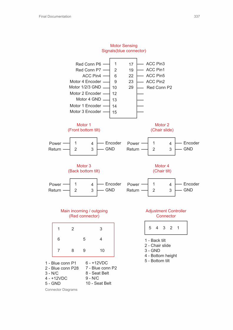
Final Documentation 337
Motor Sensing Signals(blue connector)
1269
1012131415
2923221917 ACC Pin3
ACC Pin4Motor 4 Encoder
Motor 1 EncoderMotor 3 Encoder
Motor 2 EncoderMotor 1/2/3 GND
ACC Pin1
Motor 4 GND
ACC Pin5ACC Pin2Red Conn P2
Red Conn P6Red Conn P7
Motor 1(Front bottom tilt)
12 3
4 EncoderGND
PowerReturn
Motor 2(Chair slide)
12 3
4 EncoderGND
PowerReturn
Motor 4(Chair tilt)
12 3
4 EncoderGND
PowerReturn
Motor 3(Back bottom tilt)
12 3
4 EncoderGND
PowerReturn
1 - Blue conn P12 - Blue conn P283 - N/C4 - +12VDC5 - GND
Main incoming / outgoing(Red connector)
1 2 3
4
10987
6 5 1 - Back tilt2 - Chair slide3 - GND4 - Bottom height5 - Bottom tilt
Adjustment Controller Connector
5 4 3 2 1
6 - +12VDC7 - Blue conn P28 - Seat Belt9 - N/C10 - Seat Belt
Connector Diagrams

Final Documentation338
To Controller Input
2
1
450 700
S?SW - SPDT
GND
3
The second objective was to figure out how the switches on the chair worked in conjunction with the electronic controller. Figure Switch box controller schematic displays the circuit schematic that was designed to work with a switch box the team created. Since the controller circuit schematics was proprietary and could not get access to it, the team tapped onto the seat control adjustment connector while hooked up with the controller. It was observed that no 12VDC power line was being routed into the connector but a GND (ground) line was. This immediately meant that the switches, when closed, were switching to GND. The next thing that was discovered that the switches were momentary single-pole double throw and the resistances on each of the throws could be measured. One resistance was measured as ~700ohms while the other resistance was measured as ~450ohms. Since only five signal lines were routed into the seat adjustment connector and one was GND, the other four signal lines corresponded to the four different switches that could be activated. Each switch has two options, either forward or backwards direction. This led the team to uncover that the controller used an analog-to-digital converter onboard to be able to sense whether the voltage from the switch side corresponded to the 450ohm or the 700ohm side of the switch, resulting in the motor to spin forward or backward.
Once the switches were figured out, a manual switch box was created so that the chair could be controlled from a remote area rather than from the switch controls on the chair. Figures Switch control box 1 & 2 display the manual switch box that the team designed.
Force Sensors
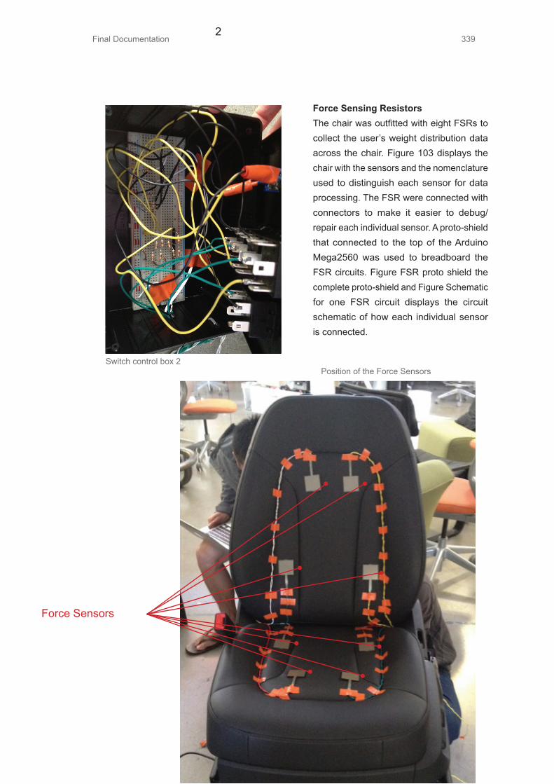
Final Documentation 3392
Force Sensing ResistorsThe chair was outfitted with eight FSRs to collect the user’s weight distribution data across the chair. Figure 103 displays the chair with the sensors and the nomenclature used to distinguish each sensor for data processing. The FSR were connected with connectors to make it easier to debug/repair each individual sensor. A proto-shield that connected to the top of the Arduino Mega2560 was used to breadboard the FSR circuits. Figure FSR proto shield the complete proto-shield and Figure Schematic for one FSR circuit displays the circuit schematic of how each individual sensor is connected.
Force Sensors
Switch control box 2 Position of the Force Sensors

Final Documentation340
+5VDC
R6FSR
R73.3K
GND
3
The FSRs are essentially potentiometers (variable resistors). The amount of force applied to the sensor pad is inversely proportional the amount of resistance across the terminals of the FSR. Within the circuit that was used, the more force applied, a larger voltage drop is seen where the connection to the analog input pin is tapped. The onboard ADC was used to convert this voltage of 0-5V range to a 10-bit digital value. A higher digital value corresponds to more force applied. The Arduino collects the data from a each sensor approximately 40 times per second and sends the raw data via serial communication to Matlab for further post processing. During initial user testing, it was observed that the density of FSRs that were implemented were not sufficient in determining the weight distribution of the user over the entire chair.
The FSRs only detect how much pressure is applied to the pad and not where the pressure is being applied to on the pad. For FSRs to work, higher density of sensors needs to be placed in localized areas to obtain a better weight distribution.
MATLAB ProcessingMATLAB was used, via serial communication with the Arduino, to collect the raw data from the sensors and the timestamp that marked the data to notify the user’s transition between activities. MATLAB saved the FSR data and time stamp in text files. Post processing scripts (Appendices) took the information within the text files and constructed visual plots of the data, separated by top and bottom. The team analyzed these plots and the user test videos together to verify that the user’s
: FSR Proto Schematic for one FSR circuit

Final Documentation 341
Schematic for one FSR circuitvisual data represented the patterns in the plot. Figure Plots of FSR data from a user test displays a user’s test data plotted for analysis. The plots were constructed to the same nomenclature outline to make it more intuitive.
7.27.2 Design Specifications For
Anticipatory System
This prototype system consists of 5 subsystems that all work in conjunction to provide the user with an interactive responsive chair experience as seen in Figure Subsystem component diagram. These subsystems include the Microsoft Kinect (IR Camera), Force Sensors and Board, Chair Rotation Mechanism, Steering Wheel Mechanism, and Motor Relay Driver with Motor Position Detection. The Microsoft Kinect used and coded to detect specific poses or gestures that would indicate whether the user wanted to be in driving mode or autonomous mode. The force sensors and board were used to collect the data used to determine chair tilt body intentions to recline or incline the seat back. The chair rotation mechanism allowed for the chair to rotation approximately 20 degrees to help users sitting more comfortably while talking to a friend or reach something from the back seat. The steering wheel mechanism allowed the steering wheel to be hidden when not in use and to emerge when the user wants to drive. And lastly, the motor relay driver and motor position detection would enable motors in order for the chair to reactive to these user (gesture and intentional body commands) and force sensor inputs.
Plots of User Test Data

Final Documentation342
Arduino
IR Camera (Kinect)
Force Sensor Board
Chair Rotation Mechanism
Steering Wheel Mechanism
Motor Relay Driver Motor Position Sensing
Relay Driver Board
The team designed a custom motor driving and position-sensing controller to allow the closed loop functionality. The OEM controller that came with the chair was not used because modifications to the microcontroller could not be accessed. The team re-engineered the controller by visual inspections of the unit and determined how exactly the controller knew where the position of the chair’s motors were at all the time.
To be able to gain control over the motors, H-Bridge circuits were created out of DPDT switches to allow the motors to spin backwards and forwards, as shown in Figure 108. SPDT switches were used to connect +12VDC or GND to supply power or lock the motor. The circuit schematic displays only one relay setup. Since there are four
motors on the seat, one motor to control the steering mechanism, and one to control the rotation mechanism, six individual relay circuits were designed in parallel on a protoboard, as shown in Figure Relay driver circuit schematic and board 1 & 2. SPDT switches were used to connect +12VDC or GND to supply power or lock the motor.Load current measurements were obtained
Reley Driver Circuit Schematics

Final Documentation 343
Motor control
Enable power
M
GND
Motor
K2RTE24005F(Relay DPDT)
K1ORWH-SH-105H-3F(Relay SPDT)
D11N5817
D31N5817
D3
GND
GND
+12VDC
prior to selecting parts to build the relay board. Load currents while the motors were running were approximately 3-4A with an average weight of 120lbs. As the motors reached and stalled at their running limits, the stall current was approximately 9A. The DPDT and SPDT switches were chosen with current ratings of 10A and with a switching coil voltage of 5VDC. This coil voltage was pertinent since the board was designed so the microcontroller logic levels would be able to control the switches. A 10A current rating seemed reasonable since the team knew that software would prohibit the motors to run until they stalled out. 1N5817 Schottky diodes were applied across the coil control inputs and between +12VDC and GND. Since motors and coils have inductive properties, as the motor switches between
the forward and backward positions back electromagnetic field spikes are generated. These spikes can potentially damage parts and disrupt/create noise on sensitive logic signals in the nearby area.
During initial testing of the entire prototype, the team discovered that to create a more refined experience for the user, the transitions between chair positions must be smooth and non-intrusive. The on/off control signals to the motor did not provide the experience that the team ultimately desired so future designs of the relay board will replace the SPDT switches, that supplied power to the motor, with Darlington power transistors and appropriate heat sinks to dissipate the wasted energy. The relays had a switching time of approximately 10ms.
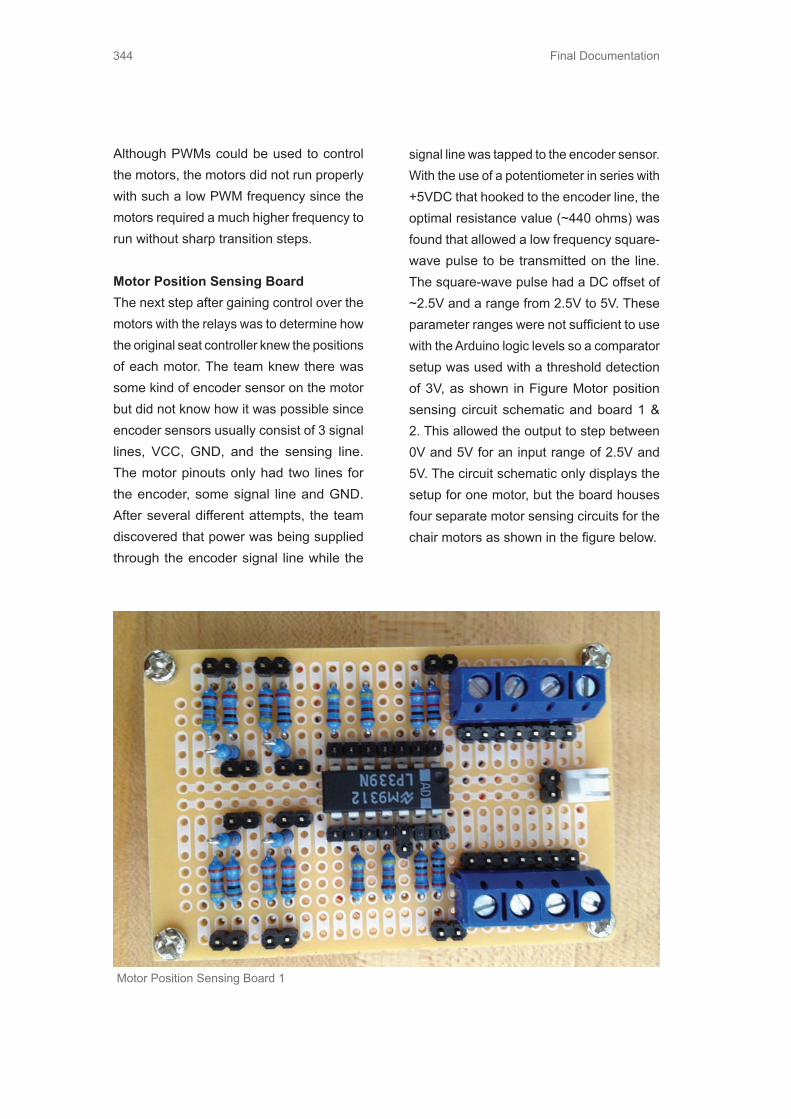
Final Documentation344
Although PWMs could be used to control the motors, the motors did not run properly with such a low PWM frequency since the motors required a much higher frequency to run without sharp transition steps.
Motor Position Sensing BoardThe next step after gaining control over the motors with the relays was to determine how the original seat controller knew the positions of each motor. The team knew there was some kind of encoder sensor on the motor but did not know how it was possible since encoder sensors usually consist of 3 signal lines, VCC, GND, and the sensing line. The motor pinouts only had two lines for the encoder, some signal line and GND. After several different attempts, the team discovered that power was being supplied through the encoder signal line while the
signal line was tapped to the encoder sensor. With the use of a potentiometer in series with +5VDC that hooked to the encoder line, the optimal resistance value (~440 ohms) was found that allowed a low frequency square-wave pulse to be transmitted on the line. The square-wave pulse had a DC offset of ~2.5V and a range from 2.5V to 5V. These parameter ranges were not sufficient to use with the Arduino logic levels so a comparator setup was used with a threshold detection of 3V, as shown in Figure Motor position sensing circuit schematic and board 1 & 2. This allowed the output to step between 0V and 5V for an input range of 2.5V and 5V. The circuit schematic only displays the setup for one motor, but the board houses four separate motor sensing circuits for the chair motors as shown in the figure below.
Motor Position Sensing Board 1

Final Documentation 345
T1
T2 T3
T5
T4 T6
B2
B6B5
B1
B3 B4
R21K R3
Res1
470
1KR5
R4A
6
3
1 1K
12
7 +
-
R21K
GND
GND
+5VDC
+5VDC +5VDC
U1ALP339
GND
OUTPUT
Force Sensing ResistorThe same square FSR and circuit schematic were used as in the funky prototype. Four additional FSR, a total of 12 FSR, were
placed in areas that would be beneficial to obtain weight distribution data from. The sensor layout can be seen in Figure FSR layout on the chair 1 & 2.
Figure 111: Motor Position Sensing Board 2
FSR Layout on the chair

Final Documentation346
OUTIN7IN6IN5IN4IN3IN2IN1IN0ABVSS
VDDIN8IN9
IN10IN11IN12IN13IN14IN15
INHIBITCD
T3T4T5T6
GNDCONTROL_CCONTROL_D
T2T1B6B5B4B3B2B1
CONTROL_ACONTROL_B
TI - CD4067BE
CD4067BE
GND
OUT+5VDC
Instead of the FSR circuits attached to an Arduino protoshield, a dedicated board was built. The previous protoshield required eight analog inputs to be used on the Arduino. The best way to utilize I/O ports on the microcontroller was to design a board that incorporated a 16-to-1 analog multiplexer (with digital control lines) to select between each of the 12 FSRs. This multiplexer only required one analog input rather than directly connecting each FSR to an analog input. Figure FSR circuit schematic and board, displays the newly re-designed FSR board.
Kinetic Camera SoftwareThe Kinect camera from Microsoft was used in conjunction with the FSRs in order to better detect the body positions and movements of the user. During the funky prototype user testing, the team determined that the FSR data was not accurate enough
to distinguish between unintentional and intentional movements. One way to help filter out the noise and small movement adjustments was to use another sensor (the Kinect camera). The Kinect has been a very popular device to develop gesture based recognition applications for a variety of
FSR Board
FSR circuit schematics
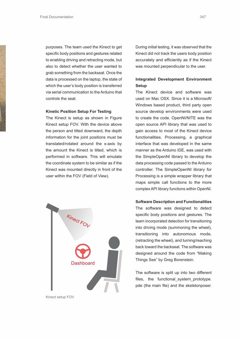
Final Documentation 347
FSR Board
Kinect FOV
Dashboard
purposes. The team used the Kinect to get specific body positions and gestures related to enabling driving and retracting mode, but also to detect whether the user wanted to grab something from the backseat. Once the data is processed on the laptop, the state of which the user’s body position is transferred via serial communication to the Arduino that controls the seat.
Kinetic Position Setup For TestingThe Kinect is setup as shown in Figure Kinect setup FOV. With the device above the person and tilted downward, the depth information for the joint positions must be translated/rotated around the x-axis by the amount the Kinect is tilted, which is performed in software. This will emulate the coordinate system to be similar as if the Kinect was mounted directly in front of the user within the FOV (Field of View).
During initial testing, it was observed that the Kinect did not track the users body position accurately and efficiently as if the Kinect was mounted perpendicular to the user.
Integrated Development Environment SetupThe Kinect device and software was used on Mac OSX. Since it is a Microsoft/Windows based product, third party open source develop environments were used to create the code. OpenNI/NITE was the open source API library that was used to gain access to most of the Kinect device functionalities. Processing, a graphical interface that was developed in the same manner as the Arduino IDE, was used with the SimpleOpenNI library to develop the data processing code passed to the Arduino controller. The SimpleOpenNI library for Processing is a simple wrapper library that maps simple call functions to the more complex API library functions within OpenNI.
Software Description and FunctionalitiesThe software was designed to detect specific body positions and gestures. The team incorporated detection for transitioning into driving mode (summoning the wheel), transitioning into autonomous mode, (retracting the wheel), and turning/reaching back toward the backseat. The software was designed around the code from “Making Things See” by Greg Borenstein.
The software is split up into two different files, the functional_system_prototype.pde (the main file) and the skeletonposer.
Kinect setup FOV
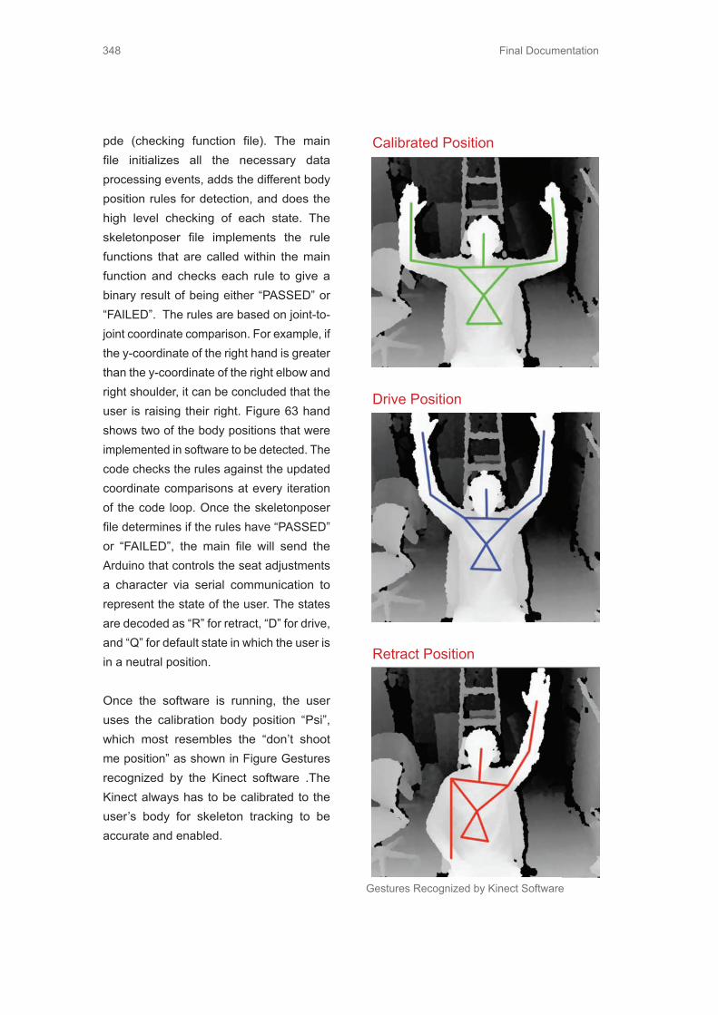
Final Documentation348
pde (checking function file). The main file initializes all the necessary data processing events, adds the different body position rules for detection, and does the high level checking of each state. The skeletonposer file implements the rule functions that are called within the main function and checks each rule to give a binary result of being either “PASSED” or “FAILED”. The rules are based on joint-to-joint coordinate comparison. For example, if the y-coordinate of the right hand is greater than the y-coordinate of the right elbow and right shoulder, it can be concluded that the user is raising their right. Figure 63 hand shows two of the body positions that were implemented in software to be detected. The code checks the rules against the updated coordinate comparisons at every iteration of the code loop. Once the skeletonposer file determines if the rules have “PASSED” or “FAILED”, the main file will send the Arduino that controls the seat adjustments a character via serial communication to represent the state of the user. The states are decoded as “R” for retract, “D” for drive, and “Q” for default state in which the user is in a neutral position.
Once the software is running, the user uses the calibration body position “Psi”, which most resembles the “don’t shoot me position” as shown in Figure Gestures recognized by the Kinect software .The Kinect always has to be calibrated to the user’s body for skeleton tracking to be accurate and enabled.
Calibrated Position
Drive Position
Retract Position
Gestures Recognized by Kinect Software
Motor

Final Documentation 349
Gestures Recognized by Kinect Software
Rotational MechanismThe rotation mechanism allowed for users to reach the backseat for an item or for parents to reach back and unbuckle their child’s car seat. Placing the chair base on a ball bearing turntable, which was also attached to a motor base, compromised the rotation mechanism as seen in Figure Rotational mechanism subcomponent. This motor base was where we also mounted our motor and gear. Attached to the chair base was a large gear, which interacts with the gear mounted to the motor. This system only allowed for a 30-degree turn, and the gears .5” thick laser-cut acrylic pieces as seen in Figure Laser cut gears for rotational mechanism. Gear profile information and motor specifications can be found in Section 9.10.4 Appendices.
Motor
Seat GearMotor Gear
Seat Base
Rotational mechanism subcomponent
Laser Cut Gears

Final Documentation350
Steering MechanismThe team designed a retractable steering wheel using a crank slider mechanism. The main concept is that the steering wheel lies flush against the dashboard when not in driving mode. This default configuration has been shown in Figure Steering wheel tucked away (disappeared) when in autonomous mode. There is also a flap, which the users can use as a work desk if they want to use that space in autonomous mode to perform some activity.
As soon as the controller gets a driving mode command it initiates the chair motion first. Once the chair is in the driving position the steering wheel motor turns for a fixed time interval (since the motor used for this prototype does not have encoders on it) and the steering wheel pops out for the users to drive. In this prototype, the steering wheel has been connected to the actual driving simulator steering wheel so that users can actually drive on the simulator, which is being projected in front of them. Giving users this simulated driving experience is
another addition to the functional prototype compared to the Funky prototype. The whole steering assembly lies on a slider the base of which is connected to the platform on which the entire setup has been mounted. The motor has been mounted in a laser cut acrylic structure, which is attached vertically to a support that goes over the mechanism. The two links and their fasteners have been chosen so that there is no interference during motion. The crank slider mechanism has been shown in Figure Crank slider mechanism for steering wheel.
Crank slider mechanism for steering wheel.

Final Documentation 351
Crank slider mechanism for steering wheel.
Arduino Code DescriptionThe motion control module has been implemented using the Move Motor functions. It takes as arguments the distance to be moved in terms of encoder ticks and the direction of motion. There is a moveComplete variable on both the motors which is set to 0 when the motors are moving. This functionality can be used to ignore motion commands when the chair is getting adjusted for a certain mode.
There is a motor stall check Boolean function that detects that a motion command is being applied and the encoder line is not ticking. When a motor stall is detected the controller immediately shuts down that motor.
The Arduino code starts with a calibration function that maxes out the two motors in one limit position. This is detected using the motor stall function. Once both the motors are maxed out the code then updates the EEPROM values of the motor position to zero. The EEPROM is used to constantly store the current motor position, so that the next time the code starts it knows what position the seat is in currently.
All the force sensors on the chair are connected to the ADC pins on the Arduino. The motor encoder lines are connected to the External Interrupt pins corresponding to INT4 and INT5. Only two motors are being currently used for this prototype – the front/back and the chair tilt motors. The Arduino code is running in a loop and detecting the force sensor values from the top portion of
the backside of the chair. It is a 10-bit ADC so the force sensor values are going from 0 to 1024. It was found through initial testing that the normal value of this force sensor reading on the back of the chair is around 450. So the upper and lower thresholds for the algorithm were then set as 150 and 700.
The software has been implemented in the form of a state machine, which keeps checking for gesture recognition commands being sent from the Kinect. These commands are in the form of characters received on the Serial port of the Arduino. As soon as a new character is detected the code feeds through the corresponding motion commands to the two motors. The force sensor smart algorithm has an override over this functionality except when in drive mode. If at any point the force sensor reading crosses the upper threshold then the algorithm initiates backward motion of the chair tilt and vice versa for tilting forward. If the algorithm detects a low on the force sensors while moving back then it stops the motion in that direction and goes to default mode. Figure Smart chair mode thresholds displays the thresholds for the chair positions.
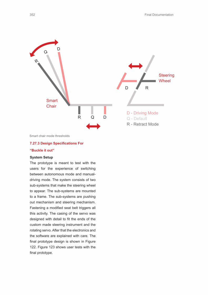
Final Documentation352
D R
R
R
Q
Q
D
D
D - Driving ModeQ - DefaultR - Retract Mode
SteeringWheel
SmartChair
7.27.3 Design Specifications For
“Buckle it out”
System SetupThe prototype is meant to test with the users for the experience of switching between autonomous mode and manual-driving mode. The system consists of two sub-systems that make the steering wheel to appear. The sub-systems are mounted to a frame. The sub-systems are pushing out mechanism and steering mechanism. Fastening a modified seat belt triggers all this activity. The casing of the servo was designed with detail to fit the ends of the custom made steering instrument and the rotating servo. After that the electronics and the software are explained with care. The final prototype design is shown in Figure 122. Figure 123 shows user tests with the final prototype.
Smart chair mode thresholds

Final Documentation 353
Final Prototype Design (top and middle)

Final Documentation354
The FrameThe base of the prototype was a chair from a Fiat Doblo that was bolted to a wooden frame. The measurements of the mock-up cabin were taken from the Audi A8. Figure 124 displays a member of the group setting the layout.
The frame was built already for an earlier Funky prototype, but the system to control the steering wheel was incorporated. The team had two ideas how to make the steering to appear as shown in Figure 125. One idea was to have a cylinder-rolling dashboard that had the steering wheel appear from the bottom of the dashboard between the legs of the driver. The concept was initially tested but was too large to fit in a normal sized car. The team took measurements from a BMW
500 taxi and validated that in this concept steering wheel would hit driver’s legs. The cabin space approximations can be seen in Figure 126. The other idea consisted of a joint-like bar that brought the steering wheel inside the dashboard and opened up like a flower for the driver (Figure 125 middle right). In the end, the team chose a solution related from the original ideas and combined the two ideas to be appearing steering wheel that came out of the dashboard, but retracted vertically in the very end of the cycle of switching modes.

Final Documentation 355
50cm
64cm
48cm
38cm
77cm
24cm

Final Documentation356
Steering Mechanism
The steering mechanism was built on ordinary gaming steering wheel where the original wheel was cut and the wires were lengthened. (Figure 127) The new steering wheel was designed to appear from the dashboard. After a flipping movement, the wheel appeared in front of the user, showing
it’s ready to be driven. Inside the casing there is a servo and the wiring for it. The wheel is a square shaped bent pipe that is mounted to a servo with a friction coupling.The servo casing was made out of prototyping plastic by milling. (Figures 128 and 129)
Gaming Steering Wheel
Servo Casing

Final Documentation 357
Steering Wheel Mechanism

Final Documentation358
Pushing Out MechanismThe appearing wheel was decided to build with a normal gaming steering wheel mounted to a table that moved linearly for a determinate amount. The prototype consisted of a bar that was connected to a rolling plate on a table while the other end was connected to a separate small piece of table on guides from an Ikea drawer. The construction was made with a 24V DC motor connected to the bar that transfered the rotational movement to a linear movement. The power was supplied from a controllable power supply. The motor was controlled
by motor controller that is able to handle 24V and more than 10 Amps. The motor controller was controlled by Teensy 2.0++ with PWM signal. The motor was operated blindly, so no feedback was given back to the microcontroller and the calibration was made with time sequence that how long time of operating the motor to a certain direction would fulfill the need of 22 cm of linear movement in the end of the bar. (Figure 131)
Pushing Out Mechanism

Final Documentation 359
Electronics
The electronics on breadboard contains Teensy 2.0++, a push button for debug, wiring for the seat belt switch, motor controller(pin 16) and servo(pin 15) wiring.
Seat belt switch
The Seat belt switch was build of a standard seat belt lock and embedded touch-sensitive switch. A hole was drilled on the back of the casing and the switch mounted with hot glue to be pressed by the existing mechanism of the lock. The switch was then connected to the Teensy 2.0++ pins with pull-up resistors and polled in the program code. (Figure 132)
Teensy 2.0++ Code Description
Code used for controlling the motor can be found from the appendix. The code has a main loop that is a modified state machine that triggers from the seatbelt switch. The button has a bouncer control that it eliminates all the false alarms from the interference of other electronics. The calibration is measured by hand and all the values are timed with the mechanical feedback of the system.

Final Documentation360

Final Documentation 361
Thank you for your time!

Final Documentation362
ME310 2013 Final DocumentationAudi Team