audio engineering magazine march 1953 - americanradiohistory
TRANSCRIPT
Selection of Tone Control Parameters-See Page
MAR(H 1953
E !\i G 1 I%l E E IR 1%l G
çianre+fl ^ Str;pe
www.americanradiohistory.comAmericanRadioHistory.Com

/
here are the
30 BEST SELLING RECORDS
OF 1952*
Record, Artist S Label
BLUE TANGO (Leroy Anderson- Deeea) WHEEL OF FORTUNE (Kay Starr-Capitol) CRY (Johnnie R y -Okeh) YOU BELONG TO ME (Jo Stafford -Columbia) AUF WIEDERSEH'N, SWEETHEART (Vera Lynn -London) I WENT TO YOUR WEDDING (Patti Page- Mercury) HALF AS MUCH ( Rosemary Clooney- Columbia) WISH YOU WERE HERE (Eddie Fisher -
DugO II'in tech alter- Victor) HERE IN MY HEART (.41 Martino -BBS) DELICADO (Percy Faith -Columbia) KISS OF FIRE (Georgia Gibbs - Mercury) ANY TIME (Eddie Fisher -Hugo Wiaterhalter- Victor) TELL ME WHY (Four Aces -Decca) BLACKSMITH BLUES (Ella Mae Morse- Capitol) IAMBALAYA (Jo Stafford- Columbia) BOTCHAME (Rosemary Clooney- Columbia) GUY IS A GUY (Doris Day -Columbia) LITTLE WHITE CLOUD THAT CRIED (Johnnie Ray- Okeh1 HIGH NOON (F'rankie Laine- Columbia) I'M YOURS (Eddie Fisher -Hugo Winterhalter- Victor) GLOW WORM (.Mille Brothers -Decca) IT'S IN THE BOOK (Johnny Standley- Capitol) SLOW POKE (Pre ITS' Ki,ny- Victor) WALKIN' MY BABY BACK HOME (Johnnie Ray -Columbia) MEET MR. CALLAGHAN (Les l'aul- Capitol) I'M YOURS (Don Cornell- Coral) I'LL WALK ALONE (Don Cornea - Coral) TELL ME WHY (Eddie Fisher-Hugo Winterhalter- Victor) TRYING (llilltoppers -Dot) PLEASE, MR. SUN (Johnnie Ray - Columbia)
Made from Audiodisc
Master
Y.
Y.
l r turning to Retail Sales, as listed in THE BILLBOARD.
Audiodiscs are
... and over 43% used adiotapr' for the original sound!
Like Audiodiscs and Audiotape, this record speaks for itself.
Of the thirty top hit records of the year, all but one were made from Audiodisc masters! And that one - a London Record - was made abroad.
It is significant, too, that the original recordings for over 43 per cent of these records were first made on Audiotape, then transferred to the master discs. This marks a growing trend toward the use of Audiotape for the original sound in the manufac- ture of fine phonograph records.
Yes - Audiodiscs and Audiotape are truly a record- making combination -in a field where there can be no compromise with Quality! t Trade Mark
AUDIO DEVICES, INC. 444 MADISON AVE., NEW YORK 22, N. Y
Export Dept.: 11 East 40th St., New York 14, N. Y., Cables "ARLAS's
manufactured in the U.S.A. under esderiys license from PYRAL, S.A.R.L., Parir
www.americanradiohistory.comAmericanRadioHistory.Com

Successor to 1 ,7c7 -Established 1917
AUDIO EPVGIIIEERING;
INCLUDING
C. G. McProud, Editor and Publisher Harrie K. Richardson, Associate Editor Ec gar M. Villchur, Contributing Editor Eve Drolet, Product on Manager Henry A. Schober, Business Manager Edgar E. Newman, Circulation Promotion S. L. Cahn, Advertising Director Elizabeth Beebee, C rculation Manager H. N. Reizes, Advertising Manager
Editorial Advisory Bcard
Howard A. Chinn
lohn D. Calvin
C. I. LeBel
I. P. Maxfield
George M. Nixon
Representatives
H. Thorpe Covington Special Representative 677 N. Michigan Ave.. Chicago 11, Ill.
Sanford R. Cowan, Mid -West Representative 67 W. 44th St., New York 18, N. Y.
West Coast lames C. Calloway J. W. Harbison
816 W. 5th St., Los Angeles 17, Calif.
CONTENTS MARCH, 1953 Vol. 37, No. 3
Audio Patents -Richard H. Dorf 2
Letters 8
Employment Register 10 New Literature 12 Audio Photographer's Checklist -Eugene F. Coricil 14
Effect of Load Impedance on Magnetic Pickup Response -Norman Pickering 19 A Power Tubé Figure of Merit -Warren G. Bender 21
The Selection of Tone -Control Parameters -Edgar M. l'illchur 22 Audio in the Year 1693 -Allen H. Fry 25 Auxiliary or Emergency Broadcast Control Room- Harold Reed 26 The Columbia "360" -Peter C. Goldmark 28 Theater Sound in A Small Package -Part 2- Thomas R. Hughes 30 Handbook of Sound Reproduction-Chapter 10 -Edgar M. I'illehur 32 1953 Radio Engineering Show 38 First Inventor Under the 1952 Patent Law- Albert If'oodruff Gray 40 Audio Fair -Los Angeles Rated Huge Success 42 Equipment Report- Pilottnler and Pilotone Amplifier 44 Record Revue- Er:yard Taman Canby 46 New Products 54 Errata 55 Industry People 71
Advertising Index 72
COVER
Recording voice on previously made film by means of magnetic sound track is becoming increasingly important in radio and TV. Reeves Soundcraft's
Magnestripe process is being demonstrated by Georgia Landeau, NBC -TV featured actress. At the left is shown the RCA Model
400 projector which reproduces both optical and magnetic sound tracks, and which incorporates a recording
amplifier for use with the Magnestripe process.
RADIO MAGAZINES, INC., P. 0. BOX 629, MINEOLA, N. Y. AUDIO ENGINEERING (title registered II. S. Pat. OIT.) is published monthly at 10 McGovern Avenue, Lancaster, Pa. by Radio Magazines. Inc.. Henry A. Schober, President; C. B. McProud, Secretary. Executive and Editorial Offices: 204 Front St., Mineola. N. Y. Subscription rates -United States, U. S. Possessions and Canada. $3.00 for 1 year, $5.00 for 2 years; elsewhere $9.00 per year. Single copies 35c. Printed in U. S. A. All rights reserved. Entire contents copyright 1953 by Radio Magazines, Inc. Entered as Second Class Matter Februay 9, 1950. at the Post Once. Lan-
caster, Pa. under the Act of March 3, 1879
> PHYSICISTS
AND
ENGINEERS
ATTENDING THE
CONVENTION NEW YORK CITY
MARCH z3 -26...
Inquiries are
invited regarding
openings on our Staff
RADAR LABORATORIES
GUIDED MISSILE LABORATORIES
ADVANCED ELECTRONIC LABORATORIES
ELECTRON TUBE LABORATORIES
FIELD ENGINEERING DEPARTMENT
> For the convenience of those attending the I. R.E. meetings and Radio Engineering Show, members of the
Laboratory Ste will be available for interviews at the
Convention hotel. For appointment telephone Hughes New York
office, LAckawanna 4 -935o.
HUGHES
RESEARCH AND DEVELOPMENT LABORATORIES
Scientific and Engineering Staff CULVER CITY, LOS ANGELES COUNTY, CALIFORNIA
Assurance is reàuired that relocation of the applicant will not cause disruption of an urgent military project.
AUDIO ENGINEERING MARCH, 1953 1
www.americanradiohistory.comAmericanRadioHistory.Com

SONOCRAFT FM TUNER
America's Most Advanced Tuner
COMPARED ... by engineers and critical music - lovers for audio -quality. and technical advancements. Consen- sus of comment: "Amazing tonal qual- ity" ... "True fidelity of reproduc- tion" ... "Live programs really sound live!"
and found con- sistently e ective for fringe -area re- ception at distances from 40 to 80 miles from New York City ... New, super- sensitive circuit assures perfect signal pick up with sufficient quieting for excellent reception even in remote locations. Automatic Frequency Con- trol (AFC) prevents station drift.
. . . because of its superior per ormance, its compact dimensions for easy mounting into almost any enclosure, its new type tuning indicator (simpler to use) and many other exclusive features .. .
* * * SPECIFICATIONS: New black -out tun- ing indicator; 3 gang inductive tun- ing; dual limiter; all coils slug -tuned; 5 microvolt sensitivity for 20db quiet- ing; 200 KC bandwidth at 6db down; adjacent channel down 60db; eleven miniature tubes plus neon- tuning in- dicator; AFC with disable switch; compact size: 10 "w., 4 "h., 8 "d.; new design for simplified installation.
SONOCRAFT FM TUNER $89.95
Write for descriptive bulletin ER which contains a complete equipment report on
this tuner.
Gitt: Come in and pick up or write for your free copy of "Sound Advice" written for Music Lovers, by Irving Greene. 124 pages of vital information in high fidelity.
Asco SOUND A
CORPORATION C
115 WEST 45th STREET, 3rd FLOOR
NEW YORK 36, N. Y.
2
ISS umitez
RICHARD H. DORF
I SEEMS that it is time once again to repeat a definition given a long time ago ::f the purpose of these monthly patent
articles. The thought arises because among your letters sometimes appears one pointing out that for this and that technical reason one of the patents described here is not all it is cracked up to be, as far as per- formance is concerned.
Now, don't get me wrong : such letters are as welcome as other mail. They show knowledge and astuteness on the part of the writers, and they often give additional food for thought. But sometimes they say in effect (often between rather than on the lines) that since the deficiency is present we ought not to describe the patent. And there's the point of disagreement.
These articles are different from most others. They don't purport to give ab- solutely reliable information right from the writer's or other engineer's mouth ; they don't mean to imply that the inventions de- scribed are either good or bad; they don't even indicate that the inventions will positively work. What they try to do is present ideas that seem interesting for any of dozens of reasons -because the approach to a problem is new or ingenious (or both), because there is an idea that could be de- veloped further, because the invention shows a somewhat different- though not neces- sarily better -way of doing a common thing, because, although the object of the invention may be unnecessary or impracti- cal, somebody did put together a weird brainstorm of a circuit, parts of which might give someone an idea that would be practical, and so on.
To a large extent, the technological his- tory of the United States is represented by its patent files. Not many of us are ingeni- ous and original enough to solve every design problem right from scratch ; and the wealth of ideas present in the flood of patents issued monthly (to which most people don't have access and the time to spend) furnishes many a take -off point for
*255 W. 84th St., New York 24, N. Y.
really good thinking and problem solving. This column is a review rather than a normal article, selecting as many interesting (to the writer, anyway) patents as space allows and turning the abstruse patent -specification language into technical English. We make every effort to either reject or plainly label patent ideas that are truly unworkable, but -paraphrasing the common radio parlance -the opinions ex- pressed are almost entirely those of the inventors.
While on the subject of mail, here is an answer for those who would like circuit component values in all the schematics. Whenever the patent furnishes them, we put them there in plain sight. If we haven't done so, they aren't available.
And now, on to this month's review.
Distortion M ement Owen E. DeLange's patent No. 2,618,686
shows a visual method of distortion meas- urement using the outphasing principle. The purpose (probably used in wideband amplifiers -the patent is assigned to Bell Labs) is to check distortion in terms of compression or expansion- nonlinearity- rather than in terms of harmonic produc- tion, though the two are, of course, rigidly related. The method is simple, requiring no precision equipment, and is shown in block form in Fig. 1.
The principle is to generate a wave of definite form, such as a sawtooth, and feed it through the system under test. The wave is simultaneously fed through a "balancing branch." The waves from the two branches are applied to a balancing circuit in which their levels are equated and the phases are made opposite. This produces cancellation provided both waves are the same (no distortion in the tested system). If there has been a change in waveform in the test branch, the resultant signal out of the bal- ancing circuit contains the difference be- tween the original and distorted forms, which is shown on an oscilloscope.
Operation is as follows : Attenuator A is adjusted so that the signal furnished the
.TOOT" 4ExfiW
SYSTEM ?y U"OE TEST
4--TEST BRANCH --. stPe. n TTE"uATO.
BALANCING BRANCH -.
Fig. 1
AUDIO ENGINEERING MARCH, 1953
I:
www.americanradiohistory.comAmericanRadioHistory.Com

9- 19. a Búl REK»O-KUT
hz -12aig 'I' Record Reproduction begins with the rotating motion of the record! This motion expresses passage of time. And each rotation is an in- terval or segment of that time. This important function is en- trusted to the turntable.
The faithfulness with wh:ch the turntable, a purely mechanical device, can perform this task, is related entirely to its design and construction. It is pretty generally known that any mechanical vibration will impose itself as undesirable elements of distortion in the reproduced sound, and that speed de- viation will result in a variation in time or tempo, and in undulating pitch.
There is no compromise with turntable qual- ity if the best in sound reproduction will be had. Engineers know this, and the name of REK-O-KUT is a byword in professional circles as the standard of turntable quality. But whether professional sound engineer or sim- ply a lover of good sound, only a fine turn- table can justify the fine equipment of a modern high fidelity system. _ t/ {, .;
Sold by Leading Distributors Write for Descriptive Literature
Among the seven REK -O -KUT Turntables available are:
Model LP743- Induction Motor Three Speeds, 33%, 45 and 78 $ 54.95
Model T -12H- Hysteresis Motor Two Speeds, 331 and 78 119.95
Model T-43H- Hysteresis Motor Two Speeds, 33% and 45 119.95
R EK - O -KUT CO. 38 -038 QUEENS BOULEVARD LONG ISLAND CITY 1, NEW YORK
Export Division: 458 Broadway, New York 12, U. S. A. Caales: Morhanex In Canada: Atlas Radio Corp., Ltd., 560 King Street W., Toronto 2B
AUDIO ENGINEERING MARCH, 1953 3
www.americanradiohistory.comAmericanRadioHistory.Com

Meet the Redheads... tops for tape recording
See how the latest additions to the Brush family of magnetic recording components can improve your tape recorders!
The BK -1090 record -reproduce head has the standard track width designed for dual track recording on /. inch tape. It pro- vides unusually high resolution and uniformity over an extended frequency range. Cast resin construction assures dimensional stability, minimizes moisture absorption, and affords freedom from microphonics. Its balanced magnetic construction, precision lapped gap, Mu -metal housing, and single -hole mounting provide important design advantages.
The BK -1110 erase head has the same basic construction as the companion record- reproduce unit. Its outstanding feature is its efficient erasing at low power consumption -less than I/: voltampere.
Investigate these new "Redheads" for your magnetic recording. Your inquiries will receive the attention of capable engineers. Write Brush Electronics Company, Department ZZ- 3,3405 Perkins Avenue, Cleveland 14, Ohio.
BRUSH ELECTRONICS INDUSTRIAL AND RESEARCH INSTRUMENTS
PIEZOELECTRIC MATERIALS ACOUSTIC DEVICES MAGNETIC RECORDING EQUIPMENT
ULTRASONIC EQUIPMENT
IM in =S. .AIM (IC(T ROMICS
COMPANY formerly
The Brush Development Co.
Brush Electronics Company is an operating unit of
Clevite Corporation.
Fig. 2.
test branch is within the nominal capabili- ties of the tested system. Then the switch in the test branch is opened and attenuator B is adjusted so that the oscilloscope trace has a peak vertical deflection of 10 divi- sions. Next the switch is closed and at- tenuator C adjusted so that the two branch outputs are balanced by placing as much as possible of the center of the resultant wave on the zero horizontal axis on the oscillo- scope screen. The peak deflection of the resultant wave then shows the amount of difference between the undistorted wave of the balancing branch and the distorted wave of the test branch. Since the original wave was set to 10 divisions peak value, each division for the resultant is equivalent to 10 per cent distortion. If the distortion is less than 10 per cent, the loss of attenua- tor D may be reduced by 20 db, which gives a factor of 10, making each division equal to 1 per cent distortion.
In high- frequency systems or video amplifiers time delay in the tested system may make coincidence of the outphased waves impossible. This can be cured by placing a variable delay line in the balancing branch to make the delays equal. At audio frequencies the delay would be very much smaller than the period of the test wave- form, so that delay would not be a problem.
The balancing .circuit might be any of several. The inventor shows a simple but quite suitable one, redrawn in Fig. 2. V, is
a phase -inverter stage which allows selec- tion of output from either plate or cathode, the one wanted depending on the output phase from the tested system. The input potentiometer is equivalent to attenuator C in Fig. 1.
The output of the phase inverter is ap- plied to the cathode of the balancing (really simply a mixing) stage, while the test branch output coming through a potenti- ometer acting as attenuator B, is applied to the grid. The output of the stage can be fed to an oscilloscope, with the vertical amplifier gain control acting as attenuator D.
Phase Splitter There are probably more phase -splitter
circuits extant than any other device in
the audio world. Almost all give unbalance problems at the extreme ends of the fre- quency range, which gives rise to response dropoffs and distortion. Here is a circuit the inventor claims will remain in perfect balance between 20 and 150,000 cps. Illus- trated in Fig. 3, it was invented by Louis R. Bourget of Sacramento, Calif., and is the subject of patent No. 2,618,711.
The circuit uses three triodes (two of which may be, as shown, the halves of a dual- triode). The first is operated as a cathode follower, with R, the volume con-
4 AUDIO ENGINEERING MARCH, 1953
www.americanradiohistory.comAmericanRadioHistory.Com

Here is the first basic advance
in tone arm design in
many decades!
The GRAY "Viscous- Damped"
108 -B Tone Arm
Gives you perfe ̂ t contact and tracking on all records at
lowest stylus pressure- virtually eliminates tone arm reso-
nances- cannot damage record if accidentally dropped.
The entirely new suspension principle of the Gray 108 -B makes it hug the grooves .. .
prevents stylus skidding on worn records - overcomes groove -jumping caused by floor
vibrations. Its "viscous- damped" design pro-
vides perfect tricking, virtually eliminates
tone arm resonances, and prevents any pos-
sibility of record damage if the arm is dropped.
G Rsiat
The 108 -B satisfies every requirement of
high fidelity reproduction. A plug -in feature
permits instant change from 78 -rpm to 33%. rpm or 45 -rpm, with automatic adjustment to
the correct stylus pressure. See and try this
"viscous- damped" arm soon - solve all your
transcription problems with this revolutionary,
versatile arm!
r Cray Research & Development Co., Inc.
I Hilliard Street. Manchester, Conn.
AND DEVELOPMENT CO., INC., HILLIARD STREET, MANCHESTER, CONN.
Division of The CRAY MANUFACTURING COMPANY -Originators of the Cray Telephone Pav Station and the Grit, Audograph and PhonAudograph
Please send me your Bulletin RF -3 on the new Gray "Viscous-Damped" 108.8 Tone Arm.
NAME
ADDRESS
CITY STATE
AUDIO ENGINEERING MARCH, 1953 5
www.americanradiohistory.comAmericanRadioHistory.Com

like it fr°14Tps ay
RAY ANTHONY The Yount' Mon Wh o Hord'
... about the famous new
slender gradient'
high -fidelity bi- directional
microphones
"315" General Purpose
LIST PRICE
$7 5.00
For high -fidelity, true -tone reproduction of voice and music, these small and rugged microphones are destined to be the favorites of leading recording artists ... singers -instrumentalists -and bands everywhere.
These microphones will outperform all other "slender" microphones- because of their advanced acoustical, electrical, and mechanical features. Both models provide a hi- directional pickup pattern -permitting greater per- former freedom (performers can stand at a 73% greater distance from the microphone!) The "300" and "315" will pick up voice and music from front and back -yet discriminate against unwanted noises from the sides. They reduce reverberation and the pickup of distracting random noises by 66%!
SHURE BROTHERS, Inc.
.cA n.. Poem. Pending
MANUFACTURERS of MICROPHONES and ACOUSTIC DEVICES
Cabre Address: SHUREMICRO 225 West Huron Street, Chicago 10, Illinois
6
50.000 .3
fig. 3.
trol and R, the cathode resistor. The secret of the circuit's success is said to be that the actual phase -splitter tubes V, and V, are fed from the same low- impedance source and the antiphase outputs are symmetrically obtained from identical plate circuits.
V, is fed as a grounded -grid stage by paralleling its cathode with that of V,; the plate output is therefore in the same phase as the circuit input. V, is a conventional grounded -cathode amplifier but the low - impedance source effectively eliminates in- put capacitance effects. Its output is, of course, out of phase with the circuit input. The output capacitances of both V. and V, should be the same, causing no unbalance such as would be obtained from the "long - tailed" or "split- load" circuits. Miller ef-
Fig. 4.
fect is probably less in V, than in J/, be- cause there is some cathode degeneration in V,.
The latter probability is cleared up in the modification of Fig. 4, where the cathode resistor of V, is left unbypassed. Cathode degeneration is then probably about equal in both tubes. This reduces the amplification of V,, which is compensated by tapping the input for V. down on R. and adding the 500 -ohm resistor for bias compensation. The circuit of Fig. 4, by the way, is suitable for d.c. amplification because of the elimination of the V, cathode bypass capacitor and the output blocking capacitors. This may inter- est instrumentation workers and direct - coupling fiends in the audio field. In either circuit, R. should be adjusted for equal plate currents through V, and V,. In Fig. 4, the tap on R. may also be touched up a little if necessary for equal audio outputs. R, need not be adjustable, of course (the best setting was found to be at 3,000 ohms) but may be useful when tubes get old or are replaced if precise balance is wanted.
Video Beckons
I should like to close this chapter with a suggestion which may provoke some audio engineers and enthusiasts (the terms are
(Continued on page 56)
AUDIO ENGINEERING MARCH, 1953
www.americanradiohistory.comAmericanRadioHistory.Com

The Inside Story
'411111111111/
The NEW CE Series
I
ACCURATE WIRE WOUND RESISTORS
HERMETICALLY SEALED IN CAST EPDXY. EXCEEDS MIL R -93A SPECIFICATION
Scientific progress has made the demand and we believe the CE series resistors are the answer: -
In the cross -section above, we illustrate the single ho-
mogenous mass that means so much to stability and provides the ample moisture vapor barrier of this new resistor. Bobbin and encapsulation become one homogenous mass, surround- ing the resistance wire with a minimum of strain.
Write today if your requirements are for a hermetically sealed resistor to withstand a wide variety of environments. Ask for the literature covering the CE series resistors.
1510 WEST VERDUGO AVENUE. BURBANK. CALIFORNIA
IN NEW YORK: Audio 8 Video Products Corporation 730 Fifth Ave. Plaza 7 -3091
EXPORT AGENTS: Frazar 8 Hansen, Limited 301 Cloy Street San Francisco, California, U.S.A.
AUDIO ENGINEERING MARCH, 1953 7
www.americanradiohistory.comAmericanRadioHistory.Com

here's
absolute reliability
for heavy duty
audio
amplification
41471 .-
I'417% r
o '`91d
oltim 'tipi
r 1
TUNG-SOL BEAM POWER AM PLI FI
If you've been looking for an audio output tube that's stable under the most severe conditions -completely dependable - then this is it! The Tung -Sol 5881 is rugged both mechanically and
electrically -and directly interchangeable with the 6L6.
In creating the 5881, Tung -Sol engineers have made lavish use
of the design and production techniques which have proved them-
selves over the past fifteen years -zirconium coating over the
carbonized metal plate and pure barium getter to effectively absorb gas for the life of the tube -gold plated wire to minimize
grid emission. These are but a few of the major design improve-
ments in the 5881.
Tung -Sol produces the 5881 under laboratory conditions, to assure peak efficiency and maximum uniformity. You'll find this
tube has the stuff to take the whole range of audio service require- ments from protracted standby periods to repeated heavy over- loads. So, if absolute reliability is essential in your audio circuits,
the Tung -Sol 5881 is a "must." Order it from your regular supplier.
TUNG -SOL ELECTRIC INC., NEWARK 4, N. J.
Sales Offices: Atlanta Chicago Culver City (Calif.) Dallas Denver Detroit Newark
T ono -Sol mates All -Glass Sealed Beam Lamps, N inlatere lumps, Signal Fluahers, Picture Tubes, Radio. TV and
Special rarpose Electron Tubes.
LETTERS Help Wanted! SIR :
A number of months ago I took up the subject of beats and combination tones with the technical editor of Radio and Hobbies in Australia. We consulted L. L. Beranek's "Acoustic Measure- ments," E. G. Weaver's ''Theory of Hearing," Watson and Tolan's ''Hearing Tests and Hearing Instruments," and Harvey Fletcher's "Speech and Hearing." As yet we have not established where in the auditory system the difference between the two exists. We would appreciate any comments on this subject which your readers would care to put forward.
JOHN F. MCDERMOTT, Flat 36, 2 Anderson St., Kingsford, N.S.W., Australia.
Stereo Photos SIR :
It is now a year since you first used stereo photos in the maga- zine, and I have been waiting for further use. I feel that they are a very good way of presenting devices that have interesting spatial features. I hope that you are continuing to solicit their use in future articles where they would be appreciated.
ROBERT P. ST. JOHN, 6606 Woodlawn Ave., Chicago 37, III.
(We still want stereo photos to illustrate articles if they will submit them, and if they do we will print them. However, it ap- pears that few of our authors remember our offer, and we shall have to use this interesting form of photography to illustrate our own articles in the future. ED.)
Editorial Distortion SIR:
Figure 11 of "Distortion in Voltage Amplifiers" in the Febru- ary issue is quite interesting. The "Horrible Example" shows about 0.1 per cent intermodulation distortion at 1 volt output, while the improved circuit shows 10 per cent. A circuit diagram illustrating the good engineering practice needed to achieve this result %mould be enlightening.
W. H. FROLICS, M. D., Steptoe Valley Hospital. East Ely, Nevada.
SIR :
I have read W. B. Bernard's article "Distortion in Voltage Amplifiers," in the February issue, with great interest, and with some dismay, particularly in regard to the curve of Fig. 11, page 55. As I interpret the curve, the improved circuit gives very much more intermodulation distortion than the unimproved cir- cuit. This is just the type of "improvement" that my little nephew makes in some of his experimental amplifiers.
It appears that the curve is either an extreme attempt at hon- esty, so that Diogenes can blow out his lantern and go back to his barrel ; or that there is a drafting error somewhere. Which?
RONALD L. Ives, 5415 Main St., Williamsville 21, N. Y.
(Well, we did it again. But this time we can't blame the drafts- man or the author. We rechecked the author's curve, and found that we had made an erroneous notation before sending it to the draftsman. We bow our editorial head in shame until the next similar error occurs. Seriously, we have requested Mr. Bernard to supply us with the improved circuit to enlighten our readers and ourselves. ED.)
Frudd Resurrected SIR :
The stripped -down, or utility model, circuit schematic ex- hibited in conjunction with the disquisition on the Frudd Audio System ought to prove no more baffling than the Frudd speaker enclosure disclosure. Detailed minutiae in a schematic are of little interest, anyway, to the intransigent audio enthusiast who invariably disregards trivia and introduces his own circuit modi- fications with the utmost savior savior. My particular modifica- tion, a highly heterodox one, consisted in constructing the circuit precisely as diagrammed. Of course, as in any high -quality audio system, care in construction pays off in performance. I can attest that in assembling the circuit only the best components should not be used.
I happened not to have available the pair of 211's specified. However, a search under the mattress (my habit of hiding my stock of components in this fashion derives from the war years
8 AUDIO ENGINEERING MARCH, 1953
www.americanradiohistory.comAmericanRadioHistory.Com

"Bill, that's what I call professional sound"
SOUNDCRAFT MAGNETIC RECORDING TAPE
Top quality for top fidelity. The kind of high -fidelity you always associate with professionals.
FOR HOME MOVIE MAKERS!
Wonderful Way to Make
"Talkies"
Soundcraft Magna- Stripe* lets you make sound movies as easily and inexpensively as silent =alms. Add sound to old silent filns. Erase and change the sound any time at all! Magna- Stripe service is availaale to you at your photographic store. Ask your dealer abou it.
T .M RS.
You'll never know how professional the sound you record on your tape recorder can be, until you use Soundcraft Magnetic Recording Tape. You'll be thrilled by Soundcraft t.igh- fidelity, delighted by the true- to-life reproduction. Soundcraft engineers are engaged in ccnstant research for new methods, materials, processes. As a result, sound engineers throughout the industry - recording studios, radio and television stations, motion picture studios - demand Soundcraft Magnetic Recording Tape for the performance perfection they need. Next time you visit your nearest dealer, ask for Soundcraft Tape. Hear for yourself the professional results of the sound you record.
REEVES
SOUNDCRAFT.. Dept. B, I O East 52nd Street, N. Y. 22, N. Y.
FREE! SOUNDCRAFT BOOKLETS
Compete iitormation on Soundcrcft Magnetic Recording Tape and Magna -Stripe.
Ycurs for the asking - just write?
www.americanradiohistory.comAmericanRadioHistory.Com

CANNON PLUGS
O SERIES
get good reception
XKW -B1 SERIES
K SERIES
V SERIES
TELEPHONE RECORDER
WRITE FOR
PRICE FOLDER
C -109
The high quality audio connectors shown above are available from all Cannon Fran- chised Distributors. In their great variety of sizes, shapes and contact arrangements there is no problem or technical requirement in the radio, sound, TV or related fields that cannot be met. Cannon plugs are standard on leading makes of audio equipment and microphones.
CANNON ELECTRIC Since 1915
M1 SERIES
Factories in Los Angeles, Toronto, New Haven, Benton Harbor. Repre- sentatives in principal cities. Address inquiries to Cannon Electric Company, Dept. C -109, P.O. Box 75, Lincoln Heights Station, Los An- geles 31, California.
See Cannon Electric Booth 2 -512 Radio Engineering Show, March 23 to 26, Grand Central Palace, N. Y.
during which electronic parts shortages drove the service shop next door to larce- nous desperation) did turn up an old WD11. (That had been under the mattress since the first World War.) This proved to be quite satisfactory as a substitute for two 211's when operated Class AB% in push pull with itself by means of an ingenious feedback circuit. Details of this circuit will not be given as it is felt that any audio man would prefer to design his own... .
This system resulted in one which was far superior to any others I have employed, and I "felt" it give forth with pure, 100 per cent fidelity, quite unadulterated by any- thing else. It is also the first audio system I have encountered that can be operated at all hours without arousing the wrath of one's neighbors. With my previous installa- tion, consisting predominantly of a one- kilowatt final feeding an unduly elaborate speaker network in a cathedral enclosure, I was continually beset by the neighbors' pounding on the floor and ceiling. As I was living by myself five miles out in the coun- try, I found this puzzling and strangely disturbing. It has remained for the Frudd system to demonstrate that for once the experts were perfectly right and that any lowbrows who thought otherwise were la- boring under a gross delusion.
I must close now because I have two visitors on the front porch. Apparently they think this is a formal affair, for they are both wearing white coats.
NORMAN F. STANLEY, P. 0. Box 895, Rockland, Maine.
Book Review F UNUAMENTALS OF AUTOMATIC CONTROL
SYSTEMS, by G. H. Farrington. 285 pp. New York: John Wiley & Sons Inc., $5.00.
Automatic control system design is rap- idly becoming the most far -reaching branch of engineering, crossing the bound- aries of all the other sciences. Although automatic control systems are not new, their study as a separate subject has only been begun recently. Audio engineers are most familiar with them in the form of feed- back amplifiers and phonograph speed regu- lators. This book is both fundamental and comprehensive. It is divided into clear logi- cal chapters which do not include material greatly detailed in other works. In partic- ular it is assumed that the reader has some familiarity with transient response studies using the Heaviside Expansion Theorem and the unit function. The matter of La- place transforms, which by now has been thoroughly labored in books on mathemat- ics, transients, and servomechanisms, is not mentioned although it may be more familiar to many of the post War II engineering graduates. Much material on types of con- trolled systems controllers, and their re- spective transfer functions is discussed. These systems are not always electrical or electrically controlled but include hydraulic and mechanical controls. Three chapters of particular interest are Transmission Lines and Distributed Constants, Multiple Con- trol, and Plant Analysis.
The book is well illustrated and includes numerous text examples but no exercises are given, which might limit its use as a college text.
-L. S. Goodfriend
10 AUDIO ENGINEERING MARCH, 1953
www.americanradiohistory.comAmericanRadioHistory.Com
in this room... there's no room for doubt There can be no room for doubt in the continuity and fidelity of your broadcast. Precisely the reason you demand -and get -the best in transmitting and studio equipment. Nor should you compromise with quality in the tape recorder you select.
In AMPEX Recorders you will find the same matchless reliability and performance you expect of your transmission equipment ... and for the same reason - they are engi- neered to the highest professional standards.
AMPEX brings you these cost - saving operating advantages: UNINTERRUPTED SERVICE Under the demand of heavy -duty programming, AMPEX Re- corders deliver thousands of hours of unbroken service. Recently a set of AMPEX heads was returned from Honolulu for routine replacement after 11,000 hours continuous use, 17 hours a day. The heads were still within AMPEX specifications for new heads and had several thousand more hours of use remaining.
MINIMUM "DOWN TIME" AMPEX Recorders are designed for thousands of hours of con- tinuous operation with minimum "down time," resulting in low maintenance costs and protection from sudden broadcast failures. ACCURATE TIMING AMPEX split- second timing accuracy protects your programs and commercials from embarrassing time overlaps.
HIGHEST FIDELITY Even when programs are repeatedly transcribed from one tape to another there is no noticeable build -up of noise level, "wow" or distortion.
LONG LIFE AMPEX Recorders are designed and built for years of service dependability. Its recordings match established NARTB stand- ards. When you have an AMPEX, you have a machine built for years -ahead performance.
IF YOU PLAN FOR TOMORROW, BUY AN AMPEX TODAY
AMPEX MAGNETIC RECORDERS
AMPEX ELECTRIC CORPORATION 934 CHARTER STREET REDWOOD CITY, CALIF.
MIMS
AUDIO ENGINEERING MARCH, 1953 11
www.americanradiohistory.comAmericanRadioHistory.Com

12
YOUR PRODUCTION DEMANDS THE EXCELLENCE OF
Precision Prints
STEP PRINTING ELIMINATES
CONTACT SHIFTS The sharpness of a print depends on close contact between original and print stock. In step printing at Pre- cision, the two films are absolutely stationary during exposure. Timing and effects are produced without notching original.
YOUR ASSURANCE OF BETTER 16mm PRINTS
15 Years Research and Spe- cialization in every phase of 16mm processing, visual and aural. So organized and equip- ped that all Precision jobs are of the highest quality.
Individual Attention is given each film, each reel, each scene, each frame - through every phase of the complex business of processing - assuring you of the very best results.
Our Advanced Methods and our constant checking and adop- tion of up -to -the- minute tech- niques, plus new engineering principle-. and ..peeial machinery
Precision Film Laboratories -a di- vision of J. A. Maurer, Inc., has 14 years of specialization in the 16mm field, consistently meets the latest de- mands for higher quality and speed.
enable us to offer service un- equalled anywhere!
Newest Facilities in the 16mm field are available to customers of Precision, including the most modern applications of elec. tronics, chemistry, physics, optics, sensitometry and densitometry- including exclusive Maurer- designed equipment -your guar- antee that only the best is yours at Precision!
PItF OiSION FILM LABORATORIES, INC.
21 West 46th St.,
New York 19, N.Y.
JU 2 -3970
NEW LITERATURE Mastro- Voice, Inc., Buchanan, Mich.,
will mail free upon written request copies of Bulletins No. 185 and No. 189, describ- ing and illustrating E -V Aristocrat, Reg- ency, and Baronet speaker enclosures, as well as complementary single and 2 -way speaker systems. Also listed and shown is the E -V Peerage equipment console, to- gether with a comprehensive table of vari- ous changers, amplifiers, and tuners with which it may be used.
Minnesota Mining and Manufacturing Co., 900 Fauquier St., St. Paul 8, Minn. discusses uses of "Scotch" electrical tapes in industrial and house wiring, under- ground cable splicing, and other heavy - duty applications in a new 12 -page hand- somely- prepared booklet. In addition there is an interesting passage which covers the use of "Scotch" glass cloth tape with ther- mosetting adhesive in sealing, holding, and insulating where elevated temperatures are involved. This booklet is an impressive example of effective industrial publishing. Available upon written request.
David Bogen Company, Inc., 29 Ninth Ave., New York 14, N. Y., under the title "Electronics for Audio -Radio -Television," is now issuing a handsome, 24 -page three - color booklet revealing the design features, specifications, and prices of the company's extensive line of high - fidelity amplifiers, public -address systems, FM -AM tuners, boosters, and allied equipment. Irrespec- tive of your interest in audio, this is a book you should have -truly one of the more worthy and complete listings of quality equipment to cross this desk in many months.
Hudson Radio as Television Corp., 48 W. 48th St., New York 36, N. Y. has just re- leased a new catalog devoted in its en- tirety to sound reproducing equipment. Intended essentially for music lovers and high -fidelity enthusiasts, the catalog is a complete directory of fine audio equip- ment, including information on public ad- dress systems, intercom systems, and re- placement parts. Available free upon re- quest by mail or in person at Hudson salesrooms.
Wells Bales, Inc., 833 W. Chicago Ave., Chicago 22, Ill. describes and illustrates a wide variety of capacitor types in a new 16 -page catalog. Of interest principally to quantity buyers, the booklet is designated Catalog C -10, and will be mailed on re- quest.
Wasserlein Mfg. Co., Inc., 126 W. Cass St., Joliet, Ill., is distributing an illus- trated brochure titled "The New Way to Solder," in which is described the rudi- ments of resistance soldering, as well as its uses for production and maintenance in industry. Also contained in the booklet are operating instructions for using the Wassco Glo -Melt resistance soldering unit. Requests for copy should specify Bulletin No. 105 -D.
Aomiola Distributing Co., 602 W. 52nd St., New York 19, N. Y. lists the complete line of Acmiola film editing, film viewing, and sound reproducing machines for pro- fessional use in a new sales bulletin. All equipment is well described and effectively Illustrated.
Equipto Division of Aurora Equipment Co., Aurora, Ill., recently announced an 8 -page catalog especially for the elec- tronics industry. Inclu.ded in the listings are such items as work benches, chassis stands, sales counters, steel shelving and bins, test stands, and warm -up racks. All are priced. Catalogs are available singly for individual use and in quantity for jobber salesmen.
AUDIO ENGINEERING MARCH, 1953
www.americanradiohistory.comAmericanRadioHistory.Com

for
Easy, Reliable ACOUSTIC MEASUREMENTS
with the SOUND -SURVEY METER e
Acoustic Engineers and Audio Enthusiasts The Type 1555 -A Sound- Survey Meter is a low -cost, portable and accurate sound meter. It enables every audio consultant or enthusiast to make measurements permitting proper installation of reproducing systems in theatres, halls, offices, plants, and living rooms. This
The G -R Type 1555 -A Sound -Survey Meter permits - * speaker placement for best coverage
* selection of optimum quantity of ab- orting material for a given speaker housing
* adjusting of base -reflex systems for best performance
* detection of room absorption defects, enabling corrective measures
* adjusting of cross -over net- works, and correct setting of levels in multiple- speaker systems
* determining levels for systems using tone-compen- sated volume controls
instrument is extremely useful to sales engineers, acoustical field engineers and consultants for pre- liminary survey work where the refinements of the larger Type 1551 -A Sound -Level Meter are not necessary.
There is no substitute for a good frequency - response characteristic. Yet, the accurate
determination of overall system response is not easily accomplished.
If sound -pressure level is meas- ured at a fixed point in a room
as frequency is changed, the response curve so ob-
tained will be very irregu- lar, even in regions of fre- quency where the system
response is actually flat. Sig- nificant characteristics, such as a "notch" produced by an
improperly adjusted cross -over network, may be completely ob-
scured. This effect is a result of rapidly changing standing -wave pat- terns with changes in frequency. That is, combinations of in -phase and out -of -phase waves cancel and reinforce each other at cer-
tain frequencies, causing abnormal "highs" and "lows" in response
curves.
Finger -tip control turns instrument on and off, selects one of three frequency character- istics, checks batteries - sound-pressure level is simply the sum of meter and attenuator readings - range is 40 to 136 db. - flush - mounted crystal microphone has good characteristics - instrument has stabilized ampli- fier and level indicator. G -R Type 1555 -A Sound -Survey Meter
$125
With the aid of the pocket -size Sound - Survey Meter, measurements at each fre-
quency may be made at several points within a room, and the results readily averaged. Re-
sults obtained may then be put in the form of a relatively smooth curve, representing the aver-
age sound level as a function of frequency, and illustrating the combined effects of speaker
acoustic power output and total room losses. Such results represent the performance of the
speaker system in its setting and thus help deter- mine effects due to absorption, room -dimensions,
speaker directivity, and standing -wave patterns.
For Complete Information Write for the G -R Sound Measurement Bulletin.
GENERAL RADIO Cómpany 275 Massochustts A , Cambria.. 39, Masfachusa/ts, U. S. A.
Hr,iSIM[arOe 9JU.S,N,A.on Art CICAOCf 1t.o,S,Sr,ordSI LOS AM JIM III
Admittance Meters it Coaxial Elements* Decade Capacitors Decade Inductors tk Decade Resistors * Distortion Meters Frequency Meters* Frequency Standards *Geiger Counters Impedance Bridges * Modulation Meters tr Oscillators Varian 4 Light Meters tr Megohmmekrs tr Motor Controls Noise Meters it Null Dekdora tr Precision Capacitors
Pulse Generaors tr Signal Generators* Vibration Meters* Stroboscopes* Wass Fillers P -H -F Mea.uing Bqui Intent ir V -T Voltmeters tr Ways Analysers tr Polariscopes
AUDIO ENGINEERING MARCH, 1953 13
www.americanradiohistory.comAmericanRadioHistory.Com

NEW! 3 Super Standard
Output
Transformers
±1 db 20- 30,000 cycles
High Efficiency Small Size
S- 510 -F, 10 watts Pri: 10,000i1CT- 8,000s1CT
Sec: 16 -852
S- 526 -F, 20 watts Pri: 6,600QCT- 5,00011CT
Sec: 16 -8.412
S- 542 -F, 40 watts Pri: 5,00011CT- 4,0009CT
Sec: 16 -8 -4g1
Dimensions Inches
Wt. lbs.
S-510-F 2 %- 23/4 -21 /a 2
S-526-F 433' -31466 -2'/ 3
S-542-F 4'i(o -3/16 -3316 5;2
Now in Stock
Write
today
for the
new
1953
Peerless
Catalog
PEERLESS Electrical Products
A DIVISION OF
9356 Santa Monica Blvd., Beverly Hills, Calif. 161 Sixth Avenue, New York 13, New 'fork
Audio Photographer's
Checklist EUGENE F. CORIELL
A UDIO TECHNICIANS and hobbyists are understandably proud of their equipment and of course want to
photograph it for themselves and poster- ity. Unfortunately, even posterity won't be impressed if the pictures do not do justice to the installation. The following checklist is based on considerable ex- perience in "shooting" audio facilities and while it will not make the reader an expert, it may help him avoid the more common errors of audio photography.
1. Decide in advance exactly what shots are desired and from what angles.
2. Make up your mind as to whether you are aiming for art or exposition. Both are certainly legitimate but this checklist is principally for the latter.
3. People add interest to pictures of equipment, but be careful they do not steal attention from the console, custom installation, etc.
4. Make sure the camera is level, ex- cept for angle shots, and that you get what the viewfinder shows. This usually calls for a tripod which will also avoid the blurring often resulting with a hand- held camera.
5. Resist the temptation to use a wide - angle lens on close -ups. It gets a wide area into the picture all right, but may introduce considerable distortion. You do not want your turntables leaning at odd angles and bulging at the top.
6. Some highlights are desirable. There's nothing like a lustrous sheen to convey the impression of quality audio gear. Carrying handles, knobs, switch - handles, hand -rubbed wooden cabinets - these are some of the items that should be shined up for highlights.
7. Be careful that highlights do not obscure equipment details you want to stand out. If flash bulbs are to be used, test for highlights in the wrong places by holding floodlamps in the proposed flash bulb positions. Attenuator dials and meter faces are often obscured by the glare of highlights. If changing the lighting positions or angles does not help, try a light film of vaseline on the offending areas.
8. Look out for undesirable back- grounds which have spoiled many a pic- ture. Keep them out by careful choice of locale and angle, proper depth of focus, adjustment of lighting, and careful cropping (cutting out undesired border areas) with subsequent enlarging if necessary. An impressive speech -input
* Major, USAF; Radio Technical Of- ficer, Armed Forces Information School, Fort Slocum, N. Y.
rack with gleaming panel assemblies is not helped by a cluttered test bench visible in the rear.
9. Make sure all meters and controls are in their desired positions. If a VU meter is to be shown with the pointer at mid -scale or other position, move it to the desired point by connection to a flashlight battery. If the shot is a close - up, make sure the channel and master gain attenuators and the VU range selector are set for the VU reading de- sired.
10. Clean up the equipment and the room. Make sure that wastebaskets, dangling wires, and other impedimenta are out of sight in the viewfinder.
11. Scratches and dents in panels, racks and table- mounted cabinets show up embarrassingly well on the finished prints, so take care of these beforehand. Soldering paste covers scratches in wooden and plastic cabinets, and grease pencils or crayons of appropriate colors do a pretty good job on metal rack sur- faces. (But see item 25, just in case ... )
12. Allow no smoking while the pic- tures are being set up . . . the smoke may fog the picture.
13. Is the hour of the day important to the photo? If so, be sure the clock ap- pearing in the picture shows the desired time ... or get rid of the clock.
14. Do certain elements in a close -up require emphasis -for example, the re- cording head of a disc recorder ? Experi- ment with spotlighting to brighten de- sired areas.
15. In close -ups, is the apparatus to be shown alone, or in its normal setting? Sometimes a shot of a console is more effective if it is framed by portions of the adjacent racks and turntables nor- mally associated with it.
16. What about shooting through con- trol room windows? Such pictures are often spoiled by glare and multiple im- ages reflected from the inclined double panes. Make sure the windows are clean, and then experiment with lighting on both sides of the glass. By using photo- flood lamps instead of flash bulbs, the lighting can be adjusted exactly as re- quired before the shutter clicks. Images reflected to the bottom of the panes from unimportant surfaces like check- ered -tile foreground floors can be elim- inated by covering that portion of the floor with a dark rug.
17. If considerable detail is wanted on patch panels, omit all patch cords. If the latter must be used for effect, use
(Continued on page 70)
14 AUDIO ENGINEERING MARCH, 1953
www.americanradiohistory.comAmericanRadioHistory.Com

SILECTROC-CORES... BIG or LITTLE ...an.y>quuiitity and any size
// W'j' /
' pA,966° AS:e ' n/)
Al .00
For users operating on government schedules, Arnold is now produc- ing C -Cores wound from 1/4, 1/2, 1, 2, 4 and 12 -mil Silectron strip. The ultra -thin oriented silicon steel strip is rolled to exacting toler- ances in our own plant on precision cold -reducing equipment of the most modern type. Winding of cores, processing of butt joints, etc. are carefully controlled, assuring the lowest possible core losses, and freedom from short -circuiting of the laminations.
We can offer prompt delivery in production quantities -and size is no object, from a fraction of an ounce to C -Cores of 200 pounds or more. Rigid standard tests -and special electrical tests where required -give you assurance of the highest quality in all gauges. Your inquiries are invited.
THE ARNOLD ENGINEERING COMPANY SUBSIDIARY OF ALLEGHENY LUDLUM STEEL CC= :PORATION
General Office & Plant: Marengo, Illinois DISTRICT SALES OFFICES
New York: Empire State Bldg. Los Angeles: 3450 Wilshire Blvd.
AUDIO ENGINEERING MARCH, 1953 15
www.americanradiohistory.comAmericanRadioHistory.Com

EDITOR'S REPORT AUDIO FAIR -LOS ANGELES
WELL, 111EY DID II ! -\'ter a series of impossible predictions as to the attendance they would have at the Audio Fair in Los Angeles, they even
went further and beat the New York attendance record by almost 50 per cent. No matter what you say, you can't beat those Californians -and this from one who hails from there, many years ago.
We can't help taking our collective hat off to the boys on the \\rest Coast, though, for their concentrated ef- fort in putting over a new event in their city. Perhaps
"the four -year build -up of interest in the whole idea of 'exhibiting audio equipment in a situation where it could be heard as well as seen served to swell the desire of the Southern California audio hobbyists and music lov- ers into a great flood which was unleashed when the ,
;doors opened on the Audio Fair -Los Angeles for the first time.
The Los Angeles Section of the Audio Engineering Society deserves plenty of credit also for its establish- ment of an Industry Advisory Council to work with the Fair officials in putting over the entire show. It in- dicates what can be done when enough people put their shoulders to the wheel simultaneously with the benefit of the whole industry at heart.
SOLID LOUDSPEAKER ENCLOSURES
With what appears to be good reason, one of our British contemporaries has been talking for years of a conventionally shaped corner bass -reflex enclosure constructed of masonry as the ultimate in speaker mounting. From an abstract viewpoint, this idea of G. A. Briggs' seems to be valid, yet relatively few of us have the courage to try it out -perhaps because of not owning our homes, or perhaps because it seemed to be too much work, or perhaps because we weren't com- pletely convinced. However, we can't help but feel a little sympathy for one of 4 's readers who was con- vinced and who did have the courage to build such an arrangement in his Vancouver, B. C., home. This en- closure consisted of an eight- and -one -half cubic foot bass -reflex speaker cabinet constructed adjacent to a fireplace in the living room, and housing a well -known 18 -inch British woofer with a free -air cone resonance of 27 cps. With a port area of 54 square inches- dimen- sions being six by nine inches -his enclosure exhibited two resonant peaks of equal intensity at 30 and 40 cps. The box ( ?) was constructed of . Zonolite concrete poured around asbestos cement -board forms, and with the front panel of one -inch slate.
Nothing was wrong with this installation except that our reader obtained a new position in Montreal, necessitating the sale of the Vancouver house. Removal of the enclosure would have involved considerable ex- pense in new carpentry, painting, and so on, but leaving the 18 -inch woofer was unthinkable, as we would all agree.
Therefore, using considerable ingenuity, this reader
removed the grille cloth and trim, increased the port dimensions to 11 by 22 inches, using a saw attachment on his electric drill, so as to permit getting his head and shoulders inside the box to unbolt the precious speaker. Remember, this front panel was a one -inch slab of slate.
The remainder of the box remains in the house, where its new owner is using it as a woodbox, since it is right next to the fireplace. And our reader is looking all around Montreal for a 30 by 40 inch slab of half to one -inch slate.
Our first reaction to this is that the enclosure must have been pretty good to warrant so much work, and we invite readers' experiences with similar installations. Our second reaction is simply one of reminiscence -we once sold a house which had an eight cubic foot bass reflex enclosure built in -wood, of course, but quite solid. The new owner sawed out the front panel and used the opening as a niche to accommodate his six -tube open- backed radio console.
At this late date, we wonder what the effect of such a niche was on the frequency response of the radio set.
FM STATION PROMOTION One interesting method whereby listeners to a favor-
ite FM "good music" station may help to ensure the continuance of broadcasting has been inaugurated by KISW -FM, in Seattle, Washington. In a letter ad- dressed to subscribers to the monthly program maga- zine, KISW listeners are described as a minority among radio listeners in the area, but they are of the type of minority who support the symphonies, the art museums, the drama productions, and the good music programs in a city. Since the station's commercial revenue is in- sufficient to meet operational costs, some other means of augmenting the income is necessary.
One solution to this emergency that appears to be workable is the formation of a KISW Listeners' Com- mittee which would purchase KISW broadcasting time. The Listeners' Committee will therefore become a KISW advertiser, and money raised by the Committee will not only meet the station's operating deficit but will enable the station to extend and improve its pro- gramming.
Listeners can join the Committee by mailing their subscriptions in care of the station. If KISW is worth the price of a one -dollar movie ticket per month, listen- ers are asked to send in twelve dollars ; if it is equiva- lent to a theatre or concert ticket per month, they are asked to send $36 or $48. The first two dollars will be used for a subscription to the monthly program maga- zine-or a renewal thereof -and the balance goes into a fund to be used to purchase broadcasting time.
Many music lovers would welcome an opportunity to aid in the furtherance of this type of broadcasting, and if such a plan were put into effect in many stations of this type throughout the country, it is probable that some of the financial problems would he alleviated. We shall watch with interest the results of this plan.
16 AUDIO ENGINEERING MARCH, 1953
www.americanradiohistory.comAmericanRadioHistory.Com

" a7 la nie
-2/ Pf ,/1
... it comes to you in the subtle shading of a piano .. .
in the clean brilliance of violins, the purity of a flute. Your ear detects
the sweet mellowness of cellos. the roundness of a clarinet ..
yes. even the iridescense of clashing cymbals. And, as the symphony swells to crescendo.
its dynamic energy acids a flood of color to your musical canvas.
For those who can hear the difference. these are the elusive pleasures
that often remain hidden in the grooves of fine recordings.
These are the thrilling new listening experiences
that are released for your enjoyment when you use quality components by Pickering.
PICKERING COMPONENTS y4 Gloóe telo cast 'teait t'li/tence "
P I C K E R I N G and company, incorporated
Pickering High Fidelity Components are
available through leading Radio Parts dis- tributors everywhere; detailed literature
sent upon request. Address Department A 1
Oceanside, L. I., New York 1111! I!I,I!II1!
AUDIO ENGINEERING MARCH, 1953 17
www.americanradiohistory.comAmericanRadioHistory.Com

"Check your air, Sir?"
To keep voices traveling strongly through telephone cables, you have to keep water out. This calls for speed in locating and repairing cable sheath leaks -a hard job where cable networks fork and branch to serve every neighborhood and street.
At Bell Telephone Laboratories, a steam of mechanical and electrical engineers devised a way to fill a complex cable system with dry air under continuous pressure. Pressure readings at selected points detect cracks or holes, however small. Repairman can reach the spot before service is impaired.
It's another example of how Bell Laboratories works out ways to keep your telephone service reliable -and to keep down the cost to you.
Air compressor and tank are at right. Long cyl- inders on rack dry air before it enters cables.
1
He's checking the air pressure in a branch cable, one of scores serving a town. The readings along the cable are plotted as a graph to find low -pressure points which indi- cate a break in the protecting sheath.
Master meters keep watch over the various cahle networks which leave a telephone office in all directions to serve a community. Air enters the system at 7 pounds pressure, but may drop to 2
pounds in outermost sections -still enough to keep dampness out.
BELL TELEPHONE LABORATORIES Imp oving telephone service fo America provides careers for creative men in mechanical engineering
www.americanradiohistory.comAmericanRadioHistory.Com

Effect of Load Impedance on Magnetic Pickup Response
NORMAN PICKERING
A discussion of operating conditions for the four popular types of magnetic pickups, together with a series of useful curves showing the effects of re- sistance and capacitance across the pickup on the over -all frequency response.
AUDIO SYSTEMS DESIGNERS and users are always greatly interested in frequency response; in fact, one
might say that they are obsessed with it. And well might they be, since nowa- days it is taken for granted that any audio system worthy of the name will have a frequency- response characteris- tic which is asymptotic to perfection. Another more cynical reason has often been advanced to explain the general and devoted attention to frequency re- sponse: it is so easily measured.
The accepted procedure for measure- ment of this parameter is to apply an in- put signal of known amplitude and fre- quency and to measure the amplitude of the output signal at each frequency. The difference between input and output sig- nal amplitudes is the absolute gain of the device, when due allowance for im- pedance ratio has been made. When all of these differences have been plotted against frequency, a frequency- response curve results. If the device being meas- ured is an amplifier it is a simple matter to achieve great accuracy. As soon as a transducer is involved, however, the measurements become much less reli- able, although hardly more difficult to make.
Transducers
For one thing, absolute gain has no meaning in transducer measurements. It is necessary to settle arbitrarily on a definition of gain in order to compare transducers. For a phonograph pickup, for example, "absolute gain" might be: microwatts output per centimeter per second r.m.s. velocity at the stylus tip. Even this is incomplete, though, since no allowance has been made for the mechanical impedance at the stylus tip.
Whenever such definitions are pro- posed they usually meet with an apa- thetic reception for one or more of the following reasons: 1. It is hard to agree on units, since metric and English units are all mixed up in the recording busi- ness. 2. Most engineers feel that pickup efficiency is not important, since ampli- fier gain is cheap. 3. Absolute gain meas- urements require much care and some relatively expensive equipment.
Pickering and Co.. Inc.. Oceanside, N. Y.
AUDIO ENGINEERING MARCH,
o T
E VOLTAGE MEASURED AS 'MECHANICAL RESPONSE'
OF THE PICKUP
L INDUCTANCE OF THE PICKUP COIL
RA. RESISTANCE OF THE PICKUP COIL AND LEADS RL LOAD RESISTANCE ACROSS THE TERMINALS
C TOTAL SHUNT CAPACITANCE BETWEEN PICKUP
TERMINALS
Fig. 1. Equivalent electrical circuit of a mag nctic pickup.
Even if we ignore "absolute" re- sponse, then, how do we determine even the relative frequency response of a pickup to a fair degree of accuracy ? The mechanical signal source is obviously of prime importance, and for practical measurements in the field is invariably a special phonograph record. This rec- ord may he an ordinary "frequency" record, a "glide- frequency" record or a "sweep- frequency" record. The usual frequency record consists of a number of bands of discrete frequencies recorded at what is hoped is a known amplitude. The glide record traverses the indicated frequency band at a slow rate, covering all of the frequencies between the start- ing and the final one. The sweep record does the same thing, but at a rapid rate (usually about 20 times per second) so that an oscilloscope can be synchronized to the sweep rate and the amplitude - frequency characteristic observed di- rectly on the screen.
Each of these records is useful -and each is subject to considerable error. The fixed -frequency record is the only one which can be calibrated, and this procedure must be carried out on each pressing if precise results are to be obtained. The general willingness to rely upon frequency records indicates a lack of awareness, on the part of the user, of the many possible chances for error in this method of measurement, yet what is the poor fellow going to do? About all that is possible is to purchase a well -made record which shows a "flat" light -pattern and to discard it as soon as the noise level shows that severe wear has taken place. With some repro-
1953
ducers, at certain frequencies, two or three playings may make a particular band unfit for further use. The mechani- cal impedance of many reproducers is such that at very high frequencies with small stylus radii, inelastic deformation of the record material may occur.
Mechanical Response
it is not the purpose of this paper to analyze the situation existing in the mechanical system of the pickup. It will be shown that whatever the basic re- sponse of the pickup, however, it will be altered by the following electrical cir- cuit, and such modifications may have a harmful or a corrective effect upon the frequency response.
If a frequency record is played by a given pickup, the open circuit response at the pickup terminals gives the desired information about the way in which me- chanical excitation of the stylus tip is converted to electrical energy. This, for lack of a better term, might be called the "mechanical response" of the pickup. This response curve must be added to the electrical response about to be dis- cussed to give the complete frequency response curve of the reproducer.
Electrical Response
Figure 1 gives a very close approxi- mation to the equivalent electrical cir- cuit for a magnetic pickup connected to an amplifier.
The useful signal voltage is that de- veloped across RL.
Network Equations
The total impedance in the circuit is:
Ra C) Zt = jwL + Ro +
which becomes:
(RoRL +0+ j (RLw'LCC RoRL 1
Zt
If E is assumed to be unity, the current
RL coC
19
www.americanradiohistory.comAmericanRadioHistory.Com

in the circuit is
E Ze
RL- C ( RaRc+C)+j(R`w'L
RoRc)
The voltage across the parallel combina- tion of C and Ri is /Zr where
1 - j RL mC Zs -
RL-j(mC)
Multiplying I by Zs, the signal voltage across the load becomes:
E out=
pacitive component, the frequency re- sponse may be calculated from Eq. (2). Figure 2 shows the results of such cal- culations for a pickup of 150 millihenries inductance and 600 ohms resistance. It will be seen that the response becomes asymptotic to 6 -db- per -octave roll -off at the high frequencies, and this fact may be used to advantage in equaliza- tion circuits for pre- emphasized record characteristics. It will further be noted that the low- frequency level of the vol- tage output is uniformly attenuated be- cause of the resistance Ro of the pickup coil. This constitutes a practical limit to the amount of attenuation which can profitably be done with only a resistor
RL+ jmRt'C [RL+Ro-Rtro'(2LC+Roc')] + j [w(RL'C+2RLRoC+L-Ri VLC')] (1)
When C = 0, the expression becomes
RL E out=
RL +Ro+ jtaL (2)
On inspection it can be seen that the output voltage in Eq. (2) will fall off at high frequencies unless RL is very large compared to 2 n f L. It is not so easy to tell from Eq. (1) exactly what is likely to happen.
Practical Values
It is in order at this point to examine the equivalent circuit and assign prac- tical values to the parameters. The user has no control over Ro and L, so the values found in four popular pickups will establish the region of operation generally encountered.
TABLE I
Inductance and Resistance of Typical Pickups
Pickup L Ro
Audak L -6 0.780 Hy. 630 ohms G. E. RPX -050 0.470 Hy. 370 ohms Pickering 140
& 120 0.150 Hy. 600 ohms Clarkstan 0.720 Hy. 1660 ohms
Frequency Response with Resistive Load
When the load has no appreciable ca-
across the terminals. In cartridges which have a high ratio of L to Ro, more high - frequency attenuation can be achieved before low- frequency losses exceed a practical maximum (say 4 db).
Figure 3 shows the frequency re- sponse for a cartridge with a high ratio of L to Ro. L is 0.472 henries and Ro is 370 ohms. It will be noted that the effect on low frequencies is very much less than in the cartridge of Fig. 2.
This information gives a good indica- tion of the nominal "impedance" of the cartridge. Since the generator imped- ance is reactive, the load resistance for flat response will depend on the induc- tive element. This is usually specified by the manufacturer to include effects of mechanical response, but for a working figure, the nominal impedance of the cartridge will be the value of 2 re fL at Eo =1.25 x 10' (approximately 20,000 cps). At this point the electrical re- sponse will be down 3 db. Figure 4 shows the nominal impedance as a func- tion of coil inductance. This illustrates clearly how the pickup with 780 milli - henries inductance can have a nominal impedance of 0.1 megohms, although its d.c. resistance is only 630 ohms.
Effect of Capacitance It is impossible to have a cartridge
connected to an amplifier without hay-
100K
SOK
r0K
70K
60K
° 50K
40K
É30K
20K
10K0 100.200 .300 400.500 .600 .700.000 .900
COIL INDUCTANCE HENRIES
Fig. 4. Nominal impedance of a magneti pickup as a function of coil inductance
ing some capacitance shunting the pickup coil. Since virtually all high - impedance installations have one pickup lead grounded, it is the sum of all the capacitances from grid to ground which is the value of C in Fig. 1.
Referring to Eq. (1), it will be seen that C figures prominently in the fre- quency response of the cartridge, but since it appears both in the numerator and in the denominator, and both posi- tively and negatively, it is difficult to see by inspection what the net effect will be.
Since C always occurs with RL, it is apparent that the factor RLC is more significant than the absolute value of C. It may be of interest to examine actual installations in order to determine pos- sible actual values of C encountered in practice.
Practical Values of Capacitance
The Miller -effect capacitance of vari- ous input tubes is listed in Table II. The tubes indicated are those usually en- countered in phonograph preamplifiers used for magnetic pickups.
The input connection to the preampli- fier is usually made by means of shielded wire. The capacitance per foot of vari- ous types of wire is shown in Table III. In addition to these capacitances, there is generally an additional capacitance of
[Continued on page 60]
10
0
10
to
zo
10
c 10
M o J EO
-¡ _ --
" -'LOAD - LOAD RESISTANCE RESISTANCE
20000
700 0
00 jj% G. E. CARTRIDGE
370
CALCULATED FREOOENCY RESPONSE
I. 472KKI RF OHMS D120 WITH VARIOUS LOADS
L 130. RG 600 OHMS
11
1
K las Icsae
fOOX
FREQUENCY IN CYCLES PER SECOND MI las
.
a
OOm me..
FREOUENCY IN CYCLES PER SECOND
Fig. 2 (left). Curves showing the frequency response of a Pickering Dl 20M pickup with various resistive loads. Fig. 3 (right). Frequency response of GE RPX -050 pickup with various resistive loads.
20 AUDIO ENGINEERING MARCH, 1953
www.americanradiohistory.comAmericanRadioHistory.Com

A Power Tube Figure of Merit WARREN G. BENDER
The author presents a simple method of evaluating power output tubes which takes into account most of the factors which are of importance in any tube application.
IT IS CUSTOMARY to define figures of merit in order to have a numerical means of examining how well a spe-
cific job is being done. Such figures of merit as the "Q" of a tuned circuit or the gain -bandwith product of an ampli- fier stage are typical examples. This article attempts to define a figure of merit for power output tubes used in home amplifiers, and to compare on this basis the tubes commonly used for this application.
The following characteristics of power tubes are evaluated in the figure of merit: power output, driving voltage, distortion, and internal impedance. Other factors such as cost and ease of eliminating hum, for example, do not appear in the figure of merit, and must be taken into account separately.
Since amplifiers for serious home use are almost without exception, push pull in operation, the evaluation of the figure of merit is in every case for two push - pull tubes. Also since home amplifiers are considered, only A and All opera- tion are tabulated.
The value of the figure of merit is given by:
FP (100D) RL E0
where F = Figure of Merit P = power output in watts D = distortion at rated output RL = load impedance in thousand ohms Ea = peak grid driving volts.
The available power appears in the numerator of the figure of merit ; thus a larger amount of power results in a larger or more desirable figure of merit.
Conversely the peak grid driving volt- age and the load impedance, which is a function of the internal impedance, ap- pear in the denominator. Thus, the fig- ure of merit is an index of the power available as modified by other factors which make the use of the tube more or less desirable. The larger the figure of merit the better is the tube.
A number of values for commonly used tubes is given in Table I.
The calculations for the 2A3 family show a marked preference for the use of fixed bias. However the choice of bias method must depend on the decision of the designer as to the return for the extra trouble of providing fixed bias.
Within this group of tubes are many differences which are not reflected in the common figures of merit. The 2A3,
* 62 Park St., Tenafly, N. J.
while a standby for almost a generation, suffers from the need of a special fila- ment voltage and old fashioned socket requirements. The six -volt equivalent - the 6A3 -has almost been completely replaced by the 6B4G and 6A5G. Of these, the latter with its unipotential cathode brought out to a separate pin, is the more modern and probably more preferable tube.
The 6AS7G suffers because of the ex- tremely high driving voltages required. The other triodes listed with their some- what better figures of merit include those types whose use is becoming more and more popular.
Of particular interest is the triode - connected 6AR6, which in this evalua- tion seems to be a very desirable tube for future exploitation.
Beam -power tubes in general, with their modest drive requirements and good power sensitivity, average a bit better than triodes. It is significant to note the high figure of merit obtained by class A 6L6's which are very com- monly used.
Non -beam -power pentodes which are less modern compare rather poorly with beam power tubes. Class A 6L6's at 10.5 watts output have a figure of merit of 1.75. The figure of merit of class A 6K6's at 9.8 watts is only 1.54.
If operation into AB, is allowed the figure of merit increases markedly, al- though this increase is attended with greatly increased difficulties of driving power, power supply requirements, etc. Fixed -bias 6L6's with 47 watts of out- put power have a figure of merit of 16.82. Similarly connected KT66's yield a value of 11.9.
It must be remembered that the Tube- Manual figures used to derive these values assume among other things, 100 per cent efficiency of the output trans- former and perfect regulation of the power supply. The first condition will not effect the value of a comparison. The second condition however, will affect the validity of a comparison between class A and All operation if the regula- tion of the power supply is not perfect. From this point of view, when using a conventional power supply, class A operation, with its smaller current vari- ations with signal, is distinctly advan- tageous, although schemes to regulate the screens of beam power tubes in class AB. do much to decrease the advantage of class A operation.
All reference to the triode vs. beam - power controversy has been purposely omitted. The figures do not show any clear advantage for either type. It is felt that this is a realistic representation of the situation. The high power sensitivity of beam power tubes makes the applica- tion of larger amounts of negative feed- back easier, which makes up for the higher generator impedance of this type of tube.
It is interesting to note the correlation between high figures of merit and popu- larity of application. The use of this figure of merit enables a numerical com- parison of the desirability of various tubes under consideration for a given amplifier. If it is desired to evaluate new tube types or other operating points, the calculations to obtain a figure of merit are straightforward and easy. Thus it is a simple matter to keep the table of figures of merit up to date.
TABLE I
Figurc of Merit
Triodes Class Bias
2A3 -6B4 etc. AB 1 Self 2A3 -6B4 etc. ABI Fixed 6AS7G A Self 6AS7G A Self 300A A Self KT66 ABI Self KT66 AB1 Self 807 -1614 AB1 Self 6AR6 A Self
Beam Tub
Power es Class Bias
6V6 AB 1 Self 6V6 -6AQ5 ABI Self KT66 AB 1 Self KT66 AB 1 Self 6L6 -5881 A Self 6L6 -5881 A Fixed 6L6 -5881 AB 1 Self 6L6 -5881 ABI Fixed
Voltage Power (watts) Figure of Merit
300 10 1.22 300 15 3.94 250 13 0.83 200 11 I .47 450 35.6 4.90 250 4.5 4.42 450 14.5 4.38 400 15 5.40
400 20 14.5
Voltage Power (watts) Figure of Merit 285 14 4.45 250 10 3.17 250 17 I 1.30 450 30 5.05 270 18.5 9.06 270 17.5 9.80 360 24.5 4.58 360 26.5 8.78
AUDIO ENGINEERING MARCH, 1953 21
www.americanradiohistory.comAmericanRadioHistory.Com

The Selection of Tone-Control Parameters
EDGAR M. VILLCHUR*
Proper design of tone controls requires a study of the conditions which must be cor- rected. The author delineates these conditions, and explains the requirements for each.
ARIOUS TONE- CONTROL circuits with given transition frequencies' and rates of boost or cut have been ex-
tensively discussed in technical litera- ture. Little has been written, however, about considerations involved in the selection of the response -curve param- eters, which sometimes seem to be chosen more or less arbitrarily. While "flat" power amplifier stages are care- fully designed for an audio- frequency response which is kept to a maximum random deviation of a fraction of a decibel, improper tone compensation (either manual or automatic) in the same amplifier may introduce, or leave uncorrected, very large inaccuracies of frequency distribution relative to the perceived original. These inaccuracies have on occasion completely over- shadowed the benefits of the above -men- tioned careful design, and have become a primary factor in determining over -all quality.
Fixed tone equalization is used when the frequency characteristics for which compensation is being made are con- stant. Modern home reproducing sys- tems contain several fixed or auto- matically variable audio equalization circuits associated with FM pre -em- phasis, recording characteristics, pick- up frequency distortion, or changes of
Contributing Editor, AUDIO ENGINEER- ING.
I The transition frequency is the inter- section of the theoretical linear slope of the response curve (a slope which the actual curve only approaches) with the frequency axis -see Fig. 5.
Fig. 3. Resultant fre- quency response of an audio system us- ing a commercial speaker in the $50 class and the treble boost of (A), Fig. 1.
15
HO
3 _s
$
i i iilin I I I lii - - -- SPEAKER RESPONSE (PRESSURE)
TONE CONTROL RESPONSE (VOLTAGE) ' - RESULTANT SPEAKER OUTPUT
M
1 - I rl
\I I / r '. J
1 l/ ' I
Ill
LLL
i s
i 10
'S
t1!
IM M 'cox
FREQUENCY IN CYCLES P IO
PER SECOND
volume level. The inclusion of such circuits does not make variable tone control superfluous, since there are many unpredictable conditions for which it may be desirable to adjust the frequency response of the reproducing equipment.
The designer of fixed equalizers does not ordinarily have to worry about what parameters to use; with certain exceptions his transition frequencies, and the required rate of boost or cut, have been exactly determined by his problem. In contrast a tone -control de- signer must furnish the means for correction, by the same circuit, of all sorts of signal aberrations. He can either provide a complex control system
which allows for equalization of almost any frequency conditions, or he can reduce the flexibility of control, choos- ing compromise response curve param- eters which are capable of producing approximate compensation for those conditions most likely to be encountered. The degree of tone -control complexity accepted in non -professional equipment has increased quite a bit since the day of the single treble -cut switch, and the most common arrangement in current audio amplifiers is a two- control, con- tinuously variable system. This allows progressive cut or boost of either bass or treble, but no independent control of the reference frequencies at which the response curves begin their slopes.
25 20' 13
;;y10
íZ 5 O z
1 '5
ó M
-15 20
YS
23 20 HS
10
-5 0
ó S
>
__- _' ...
_- _ . __ I i 10
1S
20
23
ao IM '
FREQUENCY IN CYCLES PER SECOND IMM mom M 14
FREQUENCY IN CYCLES MM
SECOND MIMI MIMI
M
Fig. 1. (A), Voltage response curves of a typical commercial tone control circuit of the R -C type, maximum positions. (B), Voltage response curve of a commercial tone control circuit of the L -R -C type, maximum positions.
22 AUDIO ENGINEERING MARCH, 1953
www.americanradiohistory.comAmericanRadioHistory.Com

A circuit which introduces a progres- sive response slope rather than uniform elevation or depression of a whole band of frequencies, besides being of far simpler design, provides the desired form of compensation in most applica- tions. It is common although not uni- versal practice for dual tone controls to use approximately the same tran- sition frequency region, usually at or below 1,000 cps, for both bass and treble variation. Figure 1 shows the response curves of two such tone con- trol circuits employed commercially.
The justification for selecting this
operator's adjustment of tone controls is in the nature of a search for maxi- mum fidelity to the perceived original, the psychological mid -point ceases to have much significance. Tone control becomes tone compensation, and the problem of response -curve parameters revolves about the question of what the controller must be equipped to compen- sate for. In the following discussion it will be assumed that the amplifier is being designed as an independent unit, and that the brands of components with which it is to be used are not known.
S0
W
Vzo W;
>Ñ
III f I I I I IIII
SOFO° 0 !lEItlVOSfD REFERENCE LEVELS OF 50 AND 110Mw CURVES OF
rEETCKII-MJN50r1 EQUAL LOUDNESS- CONTOURS. .
e0«
~ ̀%N. , .1 - _
o
¢1p
s
-1100.°:
`.
I« IM FREQUENCY IN CYCLES PER SECOND
IMO '00°O
reference frequency region is that it is considered psychologically "neutral" in pitch. It has been pointed out that 800 cps is the geometric mean between 40 and 16,000 cps, frequencies which may be taken as nominal limits of hearing under average conditions. Since the perception of frequency, like that of amplitude, closely follows the Weber - Fechner law (in that the degree of sensation varies logarithmically with the stimulus) the geometric and not the arithmetic mean of the audible fre- quency spectrum is its psychological mid -point. Thus there are about four and one -half octaves of useful audio frequencies on each side of 800 cps.
If we assume, however, that the
Fig. 4. The 50- and 80 -phon equal loud- ness contours (from Fletcher and Mun- son) superimposed.
Treble Boost
The most common purposes for which treble boost will be needed are:
1. Compensation for treble deficiencies in associated reproducing equipment.
2. Compensation for treble deficiencies in program material.
3. Compensation for discriminatory acoustic absorption with a frequency characteristic different from that of the hall or studio in which the sound origi- nated.
An additional purpose for which treble boost has on occasion been con- sidered necessary, but is not, is com- pensation for the variation in hearing frequency characteristics associated with changes of sound intensity level.
This factor, referred to as the Fletcher - Munson effect, will be discussed in the paragraphs devoted to bass boost.
Equipment treble deficiencies are usually most severe in electro- acoustic devices such as loudspeakers, pickups, and recording heads, but also occur in coupling circuits in audio or inter- mediate- frequency amplifiers.
The worst offender in a given system is ordinarily the loudspeaker. In Fig. 2 manufacturers' published on -axis re- sponse curves for six speakers in dif- ferent price ranges are plotted. Al- though the performance represented by these curves will vary greatly under different acoustical conditions t h e graphs may be taken as indicators of a general trend. There is one feature which all may be seen to have in corn - mon, and which is characteristic of the great majority of cone loudspeakers with high- frequency droop; the fre- quency region of the first two octaves above 1,000 cps, far from being attenu- ated, is accentuated (because of the new resonances introduced by cone break -up), and treble droop does not begin before 4,000 cps or higher. This fact has a significance beyond the ob- vious implication concerning compen- sation for speaker deficiencies. Any losses in the first two treble octaves which are likely to be met with from other causes will probably be compen- sated or even over -compensated by speaker characteristics.
Crystal phonograph pickups have a typical velocity response above a few hundred cps which decreases with fre- quency quite regularly up to a rather sharp cut -off somewhere between 4,000 and 10,000 cps. When this regular droop does not conform to the desired record- ing characteristic further compensation is properly provided by a fixed R -C net- work rather than by the tone control. The comparatively smooth and accu- rately predictable slope lends itself to fixed equalization, and the recommended circuits or necessary data for their de- sign are usually readily available from the manufacturer. But whether or not such a fixed network is provided, the treble boost control cannot be designed
- =
1
>
5
rI
=
o
I
'- I II
0.,{ I
VIII
I
!MiíliiQiN Af1IIIriS1IIi1, üI/I=íI11_ YT/I1Ir Hp( ---
/ I i_ajIIl f7 1'llI
!IRSI"'.Jil °
111,/IIII !IIrIIII r,`'i",1 r1111
1
a 1 I1
,
nr 1H
11 SPEAKER I11 II In tJl I --- 10 SpEAMER .l Il --- E tKANER I - 12 SPEAKER in _ E- SISEAEERE
¡kIL irisdi , , i
RI .
I«
FREQUENCY IN CYCLES RER SECOND
. MOO I00«
« I« FREQUENCY
. . . ]0000 Iae° IN CYCLES PER SECOND
Fig. 2, (A) and (B). Pressure response curves of three commercial speakers in a price range of $20 to $150.
AUDIO ENGINEERING MARCH, 1953 23
www.americanradiohistory.comAmericanRadioHistory.Com

for correct crystal pickup equalization except for the second droop, because the required transition frequency would be well into the bass region.
The contribution of high -frequency losses by other components cannot, of course, be predicted, except as to one factor ; it may be expected that losses will be confined to frequencies above the second treble octave. A survey of cir- cuit components, recording heads, etc., will indicate that it is rare for treble droop to set in before 4,000 cps or so. Even AM broa: cast band i.f. trans- formers provide, at worst, relatively even coupling to 3,000 cps.
Treble deficiencies in program ma- terial may result from low -grade studio equipment, from transmission circuits, and from old records. Such losses are almost always associated exclusively with the third and /or fourth treble oc- taves.
The writer has not found a cjuantita- tive study which compares the frequency transmission of typical living rooms with that of halls or studios, although meth- ods for room transmission measurements have been outlined.2 Therefore no com- ment will be made on the subject other than to mention the fact that room acoustics -notably t h e reverberation time versus frequency relationship -may be a factor requiring tone compensation. Reference is made to this factor under the heading of treble boost merely on the basis of subjective experience, but undoubtedly other compensations are also involved.
When treble boost is needed, then, a high transition frequency is usually de- sirable. The use of a lower transition frequency for the sake of increasing the amount of boost available at the upper end might prove satisfactory if it were not for the marked tendency of loud- speakers to emphasize the frequency re- gion of the first few thousand cps. A transition frequency of 1,000 cps or lower may cause treble boost to accentu- ate a shrillness towards which the speaker performance is already inclined, and needed boost at frequencies above 4,000 cps may carry such a penalty that
2 E. C. Wente, "The characteristics of sound transmission in rooms," J. Acous. Soc. Am., 7, p. 134, Oct., 1935.
the compensation will not be used. This unhappy effect is illustrated by Fig. 3, in which the tone -control and speaker - response curves of two high -grade com- mercial units are combined.
Determination of an optimum transi- tion frequency that will best suit the various requirements of treble boost can- not be made with precision, but it would seem that present commercial practice makes use of a frequency which is at least two octaves too low. The operator of the set may be impressed with the dramatic power of his treble boost but may still be loath to use it. (Some British manufacturers lean towards higher transition frequencies for treble emphasis-one manufacturer uses 3,500 cps.)
A single R -C network can approach 6 db per octave in rate of boost. The simplicity of the single network is one good reason for accepting this slope as the maximum, and it will prove ample for most purposes, particularly in view of the fact that treble emphasis brings to the fore harmonic distortion in the higher ranges. If the transition fre- quency is chosen as 3,200 cps -two oc- taves above 800 cps -an insertion loss of 20 db will produce something less than 12 db of maximum boost at 13,000 eps, including about 3 db of boost at the reference frequency itself. These char- acteristics seem to represent a reason- able compromise between the require- ments of all factors. The use of an even higher transition frequency might be de- sirable, but would place a greater limita- tion on the maximum boost of useful frequencies that could be achieved with a single R -C network.
Treble Attenuation
Treble attenuation is required for :
1. Compensation for varying treble pre- emphasis in recording.
2. Reduction of record suface noise and high -frequency distortion.
3. Compensation for rising treble re- sponse of associated reproducing or stu- dio equipment.
4. Tonal balance against a thin bass.
Treble pre- emphasis in recording varies considerably, and there is no standard, either of transition frequency or rate of boost, to which recording
.EO----7y =,0-
.,Q
.e
°
, » . vl I
I 1111
1lll - _ i
° e0
PIPii 11 1
iiii .. 111
FT TRANSITION FREQUENCY
n ' D IN
Ioo w00° ,WFREOENCY CYCLES SECOND
24
Fig. 5. Suggested tone control fre- quency characteris- tics, controls at maximum positions.
Fig. 6. Circuit values to approximate the curves of Fig. 5. As many of the values of the original t circuit as possible have been
retained.
companies subscribe. Table 1 lists some of the different ways in which the treble spectrum is or has been treated by rec- ord manufacturers.
Although treble recording character- istics are ideally equalized at the pickup, variable pickup equalizers are still the exception rather than the rule, and the tone -control designer must assume that at least some of the burden will fall on the treble -cut control. If the setting for minimum treble furnishes close to 6 db of attenuation per octave from a transi- tion frequency of 2,000 cps, approximate compensation for any of the recording pre -emphasis curves can be achieved.
TABLE 1
Typical Transition Frequencies Transition Rate of
Records Frequency Boost (cps) (db/
AES Standard Curve 2500 Columbia 78 & 33 1/3' 1590 RCA 78' 1000 London ffrr 78' 3000 London 33 1/3' 3000 EMI 78' - Older records
6 6 2.5 3 6
none none
Settings of the treble control which yield less than maximum attenuation will also, in most circuits, automatically shift the transition frequency higher, correcting equalization for some of the records with more gradual pre- emphasis slopes. The desirability of equalization for treble recording characteristics prior to the tone control is emphasized by the differences between the transition fre- quencies of some of these recording curves and the frequencies at which the equipment deficiencies previously dis- cussed introduce treble losses. For ex- ample, an improperly equalized disc which has been recorded with a given treble characteristic can present an un- satisfying choice between shrill and muffled reproduction, because the tone
[Continued on page 68]
3 Paul W. St. George and Benjamin B. Drisko, "Versatile phonograph preampli- fier," Aonro ENGINEERING, 33, p. 14, March, 1949.
4 D. T. N. Williamson, "High -quality amplifier modifications," Wireless World, 58, p. 173, May, 1952.
AUDIO ENGINEERING MARCH, 1953
www.americanradiohistory.comAmericanRadioHistory.Com
Audio in the Year 1693 ALLEN H. FRY`
Accidentally discovered in the New York Public Library during a search for some early papers of Harvey Fletcher, this book compiles much of the audio knowledge of its day.
THE TREATISE ON SOUND whose title page is here reproduced was written in 1693 by Caspar Ringelmann,
probably as a thesis for the doctorate. Both acoustical theory and a hypotheti- cal engineering practice are covered. Although more profound work in the theory of vibrations had already been performed by Galileo and Newton, and although Bacon's Nowlin Organum had outlined standards of scientific method which Ringelmann did not always meet, the description of contemporary acousti- cal design makes absorbing reading, and is often prophetic of modern devices.
Following are selected passages from the treatise, translated from the Latin (the language then standard for all scholarly work).
The Nature of Sound and Hearing
Sound is an oscillatory movement of the air activating the ear locally.
The inner ear has the sensory func- tion. The outer ear collects the sound and transmits it to the inner.
The motion of the air sets contiguous bodies in motion. Thus, air movements set the tympanum of the ear in motion ;
this in turn moves the Hammer which strikes the Anvil. From here on, the mo- tion is carried by air pressure differ- ences. (Note: this is inaccurate; the sound is actually propagated through the cochlear fluid.) These internal pressure differentials act upon the auditory nerves which transmit them to the brain.
Vitruviust well explained the nature of sound where he says: "Sound pro- ceeds outwardly in a series of increasing circular movements. It is as though we were to throw a stone into a pool of placid water.... Starting from the cen- ter the circles become larger and larger."
Princeton, N. J. t A classical Roman architect and writer.
DE
NATURA ET JURE
AUDITUS ac
SONI, In Illullri Univc fitate
CHRISTIA\- ALBERT1NA, Sut, PrxiLla,
l C5' (rv5, ri -r;r Dni. SAMUELJS REIHERT» JCti, Codicis nec non Matherom.
Superior. & Inferior. Prof. Ord, &c.
Praceptoris fui atatem devenerandi, Die 27. Majr, anrd 41 DC .« 111.
dnputabit
CASPAR RINGELMANN Oldenb WclfphaL
x,tx.i..r,.uw. Typis Joachimi Rcumanni, Atad. Typogr.
Fig. 1. Title page of the thesis "Of the Nature and Laws of Hearing and Sound" by Caspar Ringelmann, of Oldenburg, Westphalia, who
"will dispute" (defend the thesis) on May 27th, 1693.
Fig. 2. Ear -tubes for voice communication.
The Collection and Transmission of Sound
Acoustical ear -tubes ... work on the principle that sound is normally dissi- pated in the free and open air. By using such a tube the total vibratory movement is carried directly into the listener's ear. (See Fig. 2.) By listening to a sea -shell or large jug one can even hear the re- sidual sound produced by the otherwise quiet ambient air.
Along this same line of reasoning, it is possible to construct a building so that if a person were in one central place he could hear everything going on through- out the entire building.
Kircher (in Phonurgia Nova, 1673) discourses on some Acoustic devices
of his which will enable one to carry on a conversation from one room to another inside of a house. (See Fig. 3.) Or, out- doors between two distant places.
Construction of an Artificial Mechanism
It will be noted that the device de- scribed below substantially constitutes the input system of an acoustical phono- graph; it has a horn, a diaphragm stretched across the horn's throat, and a mechanical device attached to the diaphragm.
The term "artificial ear" refers to a device which is an actual working model of the human ear. (Figure 4). It may be used to demonstrate the mechanism of the hearing process, or in the case of auditory deficiency, to bring about a certain degree of compensation.
1. Make a little ring of metal and form the leftover end -piece into a short appendage. Let the very end of this appendage be the Anvil (c).
2. Cover the ring with a lightly - stretched membrane.
3. Glue or fasten onto the membrane the
[Continued on page 56]
ytttttttt1f111tt'g,Hltftt
Fig. 3. Seventeenth century intercoms, also useful as spy systems.
AUDIO ENGINEERING MARCH, 1953 25
www.americanradiohistory.comAmericanRadioHistory.Com
Auxiliary or Emergency
Broadcast Control Room HAROLD REED
For a total cost of $125, one engineer equipped a small storeroom to ex- tract double duty from idle remote equipment as a fixed studio installation.
THESE DAYS of intense competition III the radio broadcasting business, not to mention the additional bid for
advertisers' dollars now being made by television, it often becomes necessary for radio stations to effect every possible economy in their operations. Yet the engineering department is frequently faced with increased program and re- cording activities in spite of so- called economic operations, making the techni- cal facilities available entirely inade- quate to meet the demands of the pro- gram and commercial departments.
There are usually enough studios available, but a serious lack of studio control facilities is generally encoun- tered when numerous auditions, re- hearsals, and recordings are scheduled, in addition to the program "on the air." Studio control equipment is costly, so if anything is to be done to improve the situation it must be on the basis of making the apparatus on hand do double duty and of using any spare or obsolete pieces, modifying these units to perform a satisfactory broadcast service. One such situation as outlined above was overcome in the following manner.
Adjacent to one side of the main studio was located a small room, 12 by 7 feet, which was being used for office supplies. Arrangements were made to house these supplies in other parts of the premises and a 48 by 30 inch window
Chief Engineer WOL, 1000 Connecti- cut Ave., N.W., Washington 6, D.C.
was cut through to the main studio and three panes of glass installed to afford sound isolation. This wall, being a studio partition, was already treated for sound isolation. The cost for this work, includ- ing painting the window frame was $88.00. Nothing more was spent on this room except for varnish to improve the appearance of the floor.
Several remote amplifiers were in the plant and rarely were they all in the field simultaneously. These field ampli- fiers are Western Electric 22D models. One of these amplifiers was installed on a small, badly scratched, desk which was given a coat of commercial -looking green paint. Four lengths of flexible, shielded, microphone cable were fed through the wall and terminated in microphone input receptacles mounted in Wiremold boxes. The control room ends were terminated in connectors suitable for the microphone inputs of the 22D amplifier. Two 600 -ohm out- puts are available on these amplifiers. Flexible cables were connected to these with the other ends terminated in twist -lock connectors. These connectors plug into receptacles mounted in Wire - mold boxes and installed on the wall near the desk, from which two shielded pairs are taken to the main jack panel in the master control room. 600 -ohm terminating resistors are normally across these pairs at the jack panel end. By means of patch cords, program
material fed on either of these circuits can be dispatched to any point, the terminating resistors being automat- ically removed from the circuit when the patch cord is inserted. Figure 1
gives the layout described above and shows the tape recorder setup outlined in the next paragraph.
A portable Magnecord tape recorder, normally used for remote recording work, was placed on a small table near the 22D amplifier. This recorder is equipped with a high -impedance bridg- ing input and a 603 -ohm output, both of which appear on screw -type terminal strips. For convenience in removing and replacing this unit, small connect- ors were installed at the rear of the chassis. The bridging input is connected across output #1 of the 22D amplifier and the 600 -ohm output is fed to the 30 -ohm microphone input channel #4 through a 600 -to -30 ohm, 60 -db pad. This provides for recording, through the bridging input, any program mate- rial going into the amplifier, and to feed to the amplifier, through #4 mike chan- nel, any tape recording played on the recorder. In this way, three studio microphones and the recorder can be fed simultaneously into the amplifier or, if no recording is played, four studio microphone channels are available. The cable from the input of the re- corder is terminated in the same type of connector as the microphone cables and they are, therefore, easily inter-
Fig. 1 (left). Diagram showing interconnections between WE 22D Remote Amplifier and a portable tape recorder to provide extra studio cont of facilities. Fig. 2 (right). Block diagram to show connections for transcription turntable and monitoring amplifier and speaker.
26 AUDIO ENGINEERING MARCH, 1953
www.americanradiohistory.comAmericanRadioHistory.Com
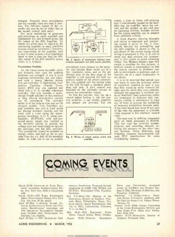
changed. Normally three microphones and the recorder input are kept in posi- tion. The 600 ohm output of the re- corder can also be fed to either line to the master control jack panel.
For aural monitoring of programs and recordings an audio amplifier and loudspeaker are also bridged across the #1 output of the 22D Amplifier. No details are given here in regard to the monitoring amplifier as many published circuits would be satisfactory. However, one requirement of the amplifier used is that it must include a high -impedance input so that it does not load the 600 - ohm output of the 22D amplifier across which it is bridged.
Transcription Facilities
An old transcription turntable' which had formerly been used for audition purposes, was salvaged. It was in good condition mechanically, but was equip- ped with a heavy, obsolete pickup arm and cartridge. A lightweight, inex- pensive, Clarkstan (Pacific Trans- ducer) #212 arm was installed and fitted with a G. E. variable reluctance cartridge. The arm includes a quick - change weight adjuster so that standard or long playing microgroove records can be reproduced. The cartridge holder is of the slide -in type and can be changed quickly. Two cartridges are kept available, one with a 3 -mil stylus for playing standard records, and the other with a 1 -mil stylus for micro- groove recordings. A G. E. phono pre- amplifier, #UPX003, with self -con- tained power supply was installed in the turntable cabinet to provide the voltage gain and equalization to operate the cartridge into the 22D amplifier. This preamplifier should be mounted on sponge rubber and kept as far as pos sible from the a.c. field of the turntable motor. In order not to use up another
Fig. 3. Details of connections between tran- scription equipment and 22D remote amplifier.
microphone input channel on the ampli- fier and because these inputs are of a low impedance value, and as the ad- ditional gain of the first stage of the amplifier is not required, the high im- pedance output of the phono preampli- fier was coupled into the second stage of the 22D through a standard phono plug and jack. A gain control was mounted on the turntable cabinet to control the preamplifier output.
So that the operator may cue up a record before feeding it into the con- trol amplifier, a cue switch, amplifier and speaker arc provided. The cue
Fig. 4. Wiring of record cueing switch and amplifier.
switch, a push to listen, self -releasing type is conveniently located on the turn- table top, the amplifier inside the cab- inet, and the speaker on the wall near the operating position. Suitable circuits for the cueing amplifier can be adapted from published circuits.
A block diagram showing turntable and cueing arrangement and monitor- ing system is given in Fig. 2. Con- nection between the preamplifier and the 22D amplifier is shown in Fig. 3, and details of the record cueing switch wiring is presented in Fig. 4. It will be noted that dual contacts are incorpor- ated in this switch to avoid continuity failure. The Western Electric type 92A switch is excellent for this purpose. A talkback system is contemplated so that the control operator or producer may talk to participants in auditions and re- hearsals via of a small loudspeaker in the studio.
It is to be observed that special care was taken to have the principal pieces of equipment installed in such a way that they would be easily removed for other uses for which they were intended, although the apparatus is normally set- up as described. Inter -connecting cables are terminated in different type con- nectors making it unnecessary to label any of them to prevent the possibility of incorrect connections between units. It has been found that about 90 per cent of the time the equipment is available when required in this auxiliary control room.
The total cost, by utilizing component parts on hand, amounted to $125.00. This low cost has provided another program and recording channel, re- lieving the pressure on the other con- trol facilities. Noise, distortion, and frequency response characteristics will meet FCC specifications for radio broadcasting stations.
V.W,§ March 23- 26- INSTITUTE OF RADIO ENGI-
NEERS, convention. Waldorf- Astoria Ho- tel, New York City. Held in conjunction with
March 23-26 -1953 RADIO ENGINEERING SHOW. Grand Central Palace, New York City. See page 38 for details.
April 28 -May 1- Seventh Annual NA- TIONAL ASSOCIATION OF RADIO AND TELE- VISION BROADCASTERS' convention and 1953 BROADCAST ENGINEERING CONFER- ENCE. Burdette Hall, Philharmonic Au- ditorium, Los Angeles.
April 28 -May 1 -1953 ELECrRoxtc COM-
PONENTS SYMPOSIUM. Presented through cooperation of AIES, IRE, RTMA, and WCEMA. Shakespeare Club, Pasadena, California.
May 7 -9 -Forty -fifth Meeting of the ACOUSTICAL SOCIETY OF AMERICA. War- wick Hotel, Philadelphia, Penna. Fea- tured subject: Sound Reproduction. Side trip to RCA Laboratories, Princeton, N. J., on May 8.
May 18-21 -1953 ELECrlOxtc PARTS SHOW. Conrad Hilton Hotel, Chicago.
August 19- 21- WESTERN ELECTRONIC
SHOW AND CONVENTION, sponsored jointly by WCEMA and Western Sec- tions of IRE. Municipal Auditorium, San Francisco, California.
September 1- 3- INTERNATIONAL SIGHT AND SOUND EXPOSITION, combined with the CHICAGO AUDIO FAIR. Palmer House, Chicago, Ill.
October 14-17 -Fifth Annual Convention of the AUDIO ENGINEERING SOCIETY, and THE AUDIO FAIR. Hotel New Yorker, New York City.
October 15-17- ACOUSTICAL SOCIETY OF
AMERICA. Cleveland, Ohio.
AUDIO ENGINEERING MARCH, 1953 27
www.americanradiohistory.comAmericanRadioHistory.Com

The Columbia "360" PETER C. GOLDMARK
Presenting the inside information about an interesting instru- ment designed to offer high quality in a ready -made form.
AT THE END of the last war, one of the programs facing the Laboratories was to develop a method whereby
recorded music of the highest quality and at the lowest cost could be brought to as many homes as possible. It was apparent that this meant a new system of music recording and music reproduc- tion which, because of the magnitude of the task, we had to tackle sequentially. The first phase of our work culminated in the development of the LP record which became the almost exclusive me- dium for recorded classical music, at a fraction of the cost of the pre -LP al- bums.
We then entered the second phase of our development program, which in- volved creating the mate for the LP record. The latter can carry a sound quality which includes everything the average human ear is capable of hearing. Until now, commercial phonographs did little justice to these records and people in their homes wanted high quality in a compact, entirely self- contained, reason- ably priced phonograph which can be placed almost anywhere in a room. He or she would also like to be able to bring the instrument home from the store, plug it into a wall socket, and play it. To fill these needs, at the same time reproduc- ing virtually everything recorded on the LP record, the Columbia "360" has been developed.
The term "High Fidelity" is usually associated with wide frequency range,
Vice- President in Charge of CBS Lab- oratories Division, 485 Madison Ave., New York 22, N. Y.
Fig. 1. The Columbia "360" phonograph, as described in the accompanying article,
yet this is not what the music lover is interested in. We were in search of something that would approach the ulti- mate in music reproduction and felt that the desired end effect could best be described as realism. The Columbia "360," shown in Fig. 1, which is the first one of a new series of music re- producers, represents the beginning to the solution of this problem and in the following paragraphs some technical details regarding the "360" will be dis- cussed.
Realism in music reproduction in- volves many ingredients which, when
28
Fig. 2. Internal ar- rangement of the cabinet with record
player removed.
properly blended, will approach as nearly as possible a lifelike rendition of the music originally recorded. Sufficient frequency range naturally is one of these and the instrument has adequate re- sponse between 50 and 12,000 cps. Most records do not contain much usable in- formation below SO or above 10,000 cps, and thus reproducing equipment with excessive capability beyond these areas can- unless properly controlled -pro- duce considerable rumble and surface noise.
Effects such as distortion and inter - modulation in the "360" were kept down to a sufficiently low limit, but again we did not choose to go overboard.
A great deal of attention was concen- trated on the most important processes involved in the translation of electrical impulses to sound waves. The phono- graph is only 17 in. wide, 10 in. high and 13 in. deep, yet the sound produced compares favorably with many a large "High Fidelity" installation.
In designing this instrument, we found it best to make the loudspeakers "take a back seat" and let the enclosure do most of the work. The sound does not emerge from a loudspeaker in front of the instrument directed straight at the listener as has been the practice to date. We found that in order to approach the illusion of reality in a room, sound should be diffused before it reaches the listeners' ears. Thus, two speakers have been provided facing outward and mounted on opposide sides of the cabi- net, as shown in Fig. 2 sound is now
AUDIO ENGINEERING MARCH, 1953
www.americanradiohistory.comAmericanRadioHistory.Com

Fig. 3. Underside of the tone arm showing the rotating stylus assembly in the cartridge. The
stylus is rotated to change from LP to 78.
radiated practically all around the in- strument (hence the name "360 ") and arrives at the listener after it has been bounced around in the room, resulting in a mixture of many different phases and amplitudes. The Record Compartment
The record itself is played in the middle of a sealed sound chamber rep- resented by the solid half -inch -thick cabinet walls. Every available air space within this enclosure has been utilized to create the desired sound and the air pressure produced by the speakers has to be preserved during playing by keep- ing the lid closed. If, while playing rec- ords, one were to lift the top even a trifle, the bass would disappear almost completely.
The changer proper is a V -M three - speed type, floating on springs within the sound chamber in such a way that there is no acoustic feedback between the pickup and the loudspeakers. The arm and cartridge have been specially
developed; the arm, made of metal, pro- duces a slight resonance of around 50 cps which plays an important role in the over -all frequency response of the sys- tem. The cartridge has been developed with the Sonotone Corporation and uti- lizes a ceramic element. A rotating needle assembly, Fig. 3, carries two sap- phire points back to back, one with a radius of one mil and the other with a radius of three mils. Needles assembles containing a diamond stylus for LP rec- ords will also be available. The fre- quency response of the cartridge -and- arm combination looking into a load of 1.0 meg. and 100 µµf, is within a few db of the required reproducing characteris- tic when using the Columbia No. 103 test record as signal source. The car- tridge compliance is of the order of 0.9 x 10⁻⁶ cm /dyne and the voltage output, using the Columbia 103 test record, is approximately 0.5 volts at 1000 cps. The stylus can easily be changed by any lay- man by raising the arm, lifting out the entire stylus assembly and replacing it with a new one.
The "360" phonograph has a loudness control instead of the usual volume con- trol, and it has a treble control instead of a tone control. At every setting of the loudness control, the tonal balance is automatically changed to give optimum reproduction for that given sound level. The treble control influences only the very high frequencies; for instance, the difference in output for the maximum and minimum treble positions is 12 db at 10,000 cps, but only 3 db at 3,000 cps. The circuit schematic is presented in Fig. 4.
The two six -inch loudspeakers are identical and have a resonance frequency of between 85 and 90 cps. Nevertheless, the over -all sound pressure output of the system is quite adequate below the speaker resonance frequency.
fI
i
18
7500 (TONE)
0.22MEG
01
01
POLARIZE PLUG FOR II MUM lul
117 Goti
V1 V2 V3 Vt
t T 7
600 10W
0.1
v2 351.6 T O
6.
v31 331.6
24 1W
TRIBE LOCATION
e BACK OF CABINET CUTOUT
Vt 352
ICI
OS,400V
ELECTRICAL GROUND
C11AS515 GROUND
1002W 10000
OBSERVE PHASING
(SEE NOTE)
40,150V TOPL5OV T0,150V
NOTE
REVERSE PHASING OF SPEAKERS WILL CAUSE LOSS OF BASS.
REVERSE PHASING OF FEEDBACK WILL CAUSE AMPLIFIER TO OSCILLATE.
Fig. 4. Over -all schematic of the "360."
AUDIO ENGINEERING MARCH, 1953
1111111111111111111111111111
mlIIIIIIC:=I111111::0111I
:'1illii::IIII11`CIIii C:aIIIIICC:IIIIIIimaiI ::IIIIII:IIIIIIC Mil IIy
Fig. 5. Measured acoustic response curve ,
compared with electrical curve of Columbia 103 test record. Curve A is response with maximum treble; B is with minimum treble.
Solid curve represents the test record.
AINTS ° ~
PP 351.6
13323
MODEL
0
20
615 R.
IS
sp
w .
- A- RESISTOR LOAD 16 OHMS
II -SPEAKER LOAD
s
A
5
0
4,1 __....... 10 1.5 t.o 2.5
VOLTS RMS ACROSS LOAD
Fig. 6. Intermodulation distortion vs. power output.
Performance
It may be of interest to explain how the sound pressure curves of Fig. 5. were taken. Instead of placing the phonograph in a sound test chamber and carrying out measurements the con- ventional way, the player was set up in a room, the acoustic properties of which approached home listening conditions. A large number of sound pressure curves were derived using different dis-
[Contin-ued on page 59]
H. P.
200C
PP 35L6 12AxT
35Z5
0.501 SPEAKER LOAD
0.10000.4 SPEAKER LOAD
13 2.0 VOLTS RBIS ACROSS LOAD
2.5
A 4001 SPEAKER LOAD
a4001 RESISTOR LOAD 1.6 DRYS
1s Lo VOLTS RMS ACROSS LOAD
23
Fig. 7. Harmonic distortion vs. power output.
29
www.americanradiohistory.comAmericanRadioHistory.Com

Theater Sound in a Small Package
THOMAS R. HUGHES
Part 2. Continuing the description of a speaker enclosure which is claimed by the designer to be superior to any other type with which he has had experience. Constructional details are given in this installment.
IN THE PRECEDING ARTICLE, the writer discussed the many practical and technical reasons why he believes
this system to be the only completely satisfactory means of properly reproduc- ing classical music in the average -size living room, and this installment is de- voted to the construction. The first as- sembly is illustrated at various stages during the building, but the views shown are just suggestions. The dimensions and proportions can be varied to fit the particular speaker and other materials at hand.
The first woofer had such a large field coil that the cabinet had to have considerable depth from the front, or face, back into the corner of the room. This meant that the face was wider also; as you can see, the base of an equilateral triangle increases with the altitude. The second assembly was built around a woofer with a permanent mag- net and was scaled down somewhat in dimensions because the smaller magnet could be fitted into the corner more snugly.
The woofer may be built up by re- moving the frame from the permanent magnet structure of an old 12- or 15 -in. spealrer and replacing it with a sturdy 8-in. frame. However, a high -quality field -coil magnet can be used, if avail- able, provided it has adequate wattage so as to provide a large magnetic flux - somewhere around 10,000 lines per sq. cm. It is necessary that the structure selected have a deep voice -coil slot, and that the pole pieces are long axially. The voice -coil diameter should be at least 1% in., and 1% in. or more would be even better.
3721 Hillcrest Dr., Los Angeles 16, Calif.
Fig. 3. Detail of one side of the metal horn covering the range from 450 to 1000 cps.
30
Fig. 4. Detail of the speaker mounting ring to be attached to the horn of Fig. 3.
Suitable speaker frames -including the magnet structure-can usually be obtained for a relatively low cost from a shop which specializes in reconing speakers. While many of the modern high -flux- density speakers would pro- vide an ideal magnet for this purpose, it would be futile to suggest disassem- bling one of them for the special type of woofer we desire. It was stated pre- viously that such speakers were rela- tively expensive, and that this design was economical.
Having secured a suitable magnet structure, it might also be possible to obtain from the same source a frame or "basket" for an 8 -in. speaker. Re- member that this basket should be as deep as possible -the one used on some of the earliest dynamic speakers is the type to obtain. Assuming that you suc- ceed in obtaining a permanent magnet unit, be sure to cover the voice -coil opening immediately with Scotch tape - either the cellophane type or that known as masking tape -to preclude the slot being filled up with metal particles. Once these particles become lodged in the voice -coil slot, it is almost impossible to remove them - although one of the most effective ways to "try" to get them out is to fold a piece of this same tape over the end of a thin strip of metal, which can then be used to "wipe" the slot. A large percentage of the filings can be removed in this manner, although some are almost certain to remain.
After you have mounted the smaller frame on the magnet the rest is up to the speaker reconing expert. He must design a steep cone of stiff parchment, such as phenolic impregnated paper, and a voice coil to handle the wattage re- quired for a small woofer. To match the average horn tweeter and utilize smaller
capacitors in the dividing network, the voice -coil impedance should be around 16 ohms at 400 cps. This isn't critical, however; a value of 8 ohms is still usable.
The most critical item is the sus- pension of this cone. It will have a much greater excursion than any normal 8 -in. speaker, so both the center spider and outer surrounding ring should be of some plasticized cloth fabric or soft leather rather than the usual molded mat of paper. These suspensions must be free in movement (not stiff) but able to stand the punishment of the greater flexing. The effective working diameter of the cone proper -its outside diameter -will probably be around 6 in.
The Intermediate Horn
Bolted to the mounting ring of the 8 -in. woofer is the direct- radiating in- termediate horn. Through this horn passes the major portion of the funda- mental notes and the drum and cymbal crashes, etc. For the low notes of the outside horn, the shape of the walls is not so important but for this inter- mediate horn we must carry the flare out in a smooth exponential curve.
To meet all requirements, a throat opening of 4% in. square works out best. Take a sheet of paper and draw an axis across the center. Then plot points on it starting with the 4 % -in. throat, so that you will have a side elevation of the horn standing on its mouth, as in Fig. 3. Measure off three divisions of 1% in. each along the axis and strike off a chord at each division, perpendicu- lar to the axis. The area of the throat opening is 20.25 sq. in. By doubling this area and extracting the square root, it is found that the span along the side at the first chord will be 6 -1/3 in. Plot
Fig. 5. Detail of the mounting of the speaker on the flange and horn.
AUDIO ENGINEERING MARCH, 1953
www.americanradiohistory.comAmericanRadioHistory.Com

Fig. 6. Completed horn, shown with the early electrodynamic driver unit used in the first
model.
half of this distance along the chord to each side of the axis. At the next chord the dimension will be 9 in. and at the mouth it will be 12A in.
Next, trace a smooth curve through the four points plotted on each side of the axis. This is best done with a "French Curve;" you may not find a curve that falls exactly on all four points but retrace the different sectors to get it as close as possible. Then use a flexible rule to measure the length of this curve to determine how long to cut the sheet metal side from throat to mouth.
To make these sides, get some 22 or 24 ga. furniture steel. 20 ga. is a little stiff for shaping but would give greater rigidity of the horn walls. On the steel, draw the axis again and then lay off the distance along the axis that was measured around the curve. Divide this distance into three equal divisions for the chords and lay off the former dis- tances across the chords for the points of the curves.
The curves will be the same for all four sides of the horn, but two of the sides must have a / -in. strip added along the edge as shown in Fig. 3. At the mouth of these two sides leave an extension of an additional 1 in. to bend over. At the throat of all four sides, leave an extended lip as shown. Cut out the two pairs of sides as drawn, and then snip out little wedge -shaped pieces from the % -in. extended edge left along the curves of two of the sides.
The flange shown in Fig. 4 must be made from furniture steel of at least 20
ga. or heavier. Cut out a circular piece the same diameter as the outside edge of the 8 in. speaker frame. Scribe a circle on it which will just clear the inner edge of the speaker gasket where it bolts on to this flange. Then mark off the 4% x 4%-in. square in the center of this circle and saw across the di- agonals with a hacksaw, as shown. Drill two rows of A-in. holes at the corners for starting a saw blade in the cuts.
Clamp the circular edge in a vise so that a 4 % -in. side of the square is flush with the edges of the vise jaws. If the vise does not have jaws wide enough, the width can be extended by two small pieces of angle iron. Bend the triangu- lar piece, between two diagonal saw cuts, inward to a 90 -deg. angle against the vise jaw. Then trim off the triangle to leave a % -in. lip as shown. Bend over the next triangle, being careful to choose the side that will let the tin snips clear the first lip just cut. Continue around for all four triangular seg- ments so that a 4% x 4 % -in. mouth opening with % :in. lips results.
The lip extensions, at the throat line of the horn sides, should be cut to match the portion of the flange they mate with, around the mouth. These lip pieces may be bent over at approximately 90 deg. and the extensions on the bottoms of two sides may be bent over in the same di- rection, to an angle of approximately 45 deg. Then the two sides without ser- rated edges may be clamped against the flange, facing each other, with the % -in. lip of the throat extending inside the horn and their upper lip pieces against the flange on the side away from the speaker gasket, as in Fig. 5.
While these pieces are clamped along the edges, drill small holes and rivet small tinner's rivets or nail stubs, so that they fall within the circle you drew to clear the speaker gasket. After rivet- ing the two sides on, they can be care- fully shaped over a large pipe or other cylindrical surface, for the horn flare curvature. Next, form the horn flare in the two remaining sides and then bend over the saw -teeth edges to the proper angle with pliers.
These saw -teeth are to reach along the outside of the other two sides and
Fig. 9. Method of mounting horns to front of cabinet structure.
allow the soldering iron point to apply heat effectively and to flow the solder between mating edges. After you are sure every thing fits properly, these re- maining two sides may be riveted to the flange at the speaker end. Some me- chanics like to tin the mating surfaces before assembling. Use a little "cut" muriatic acid on the edges and solder with half -and -half solder and a large soldering iron. Solder an inch or two at a time while clamping the edges in snug position with "C" clamps or other suitable means.
After all corners are well soldered, place the throat opening over a flat extension of the vise or an anvil and use a hammer lightly to shape the inner %-in. lip back against the inner surface of the horn for soldering. For riveting in tight places or for this shaping pro- cedure, a stiff bar or angle iron can be clamped to extend out from a strong vise. This lip should be soldered to the horn wall to kill any chance for spurious vibration between the horn and flange sections. Figure 6 shows the finished ap- pearance.
When you are through soldering there must be no visible air leaks up the cor- ners of the horn or where the flange is attached. The speaker mounting ring must have a continuous gasket to mate with this horn flange, for completing this air -tight effect. Before the speaker is bolted to the horn, solder a piece of light hardware cloth across the throat of the horn flange, leaving no free edges to vibrate.
[Continued on pn,7e 64]
SECTION T -T SECTION ItY
Fig. 7 (left). Horizontal and vertical sections through the center of the speAer unit for the second model, using a PM dynamic driver. Fig. 8 (right). Sections through first model, using the driver shown in Fig. 6.
AUDIO ENGINEERING MARCH, 1953 31
www.americanradiohistory.comAmericanRadioHistory.Com

Handbook of Sound Reproduction
EDGAR M. VILLCHUR
A discussion of the basic structure of one of the most im- portant elements of a sound system, with an analysis of the effect of constructional features on its performance.
LOUDSPEAKERS are electro- acoustic de- vices for converting the electrical output of audio amplifiers into me-
chanical and then acoustical energy. Modern loudspeakers are almost ex- clusively of the dynamic (moving -coil) type. The dynamic loudspeaker allows the electrical signal to pass through a coil which is free to move along its longitudinal axis, and which is sus- pended in a transverse, fixed magnetic field. Since the coil is made of non- magnetic material the static field exerts no force on it except when current flows. An electrical signal changing in the same complex way as the original sound pressur' will set up imitative vibrations, anti the moving `voice" coil is given a bite of the air by an attached cone or diaphragm. The efficiency of the conversion from mechanical to acous- tical energy is Increased by means of some type of acoustical coupler between the speaker and room, such as a horn or baffle.
It may be seen that the first step of the above conversion, from electrical to mechanical energy, is exactly analogous to the action of an electric motor, where current is passed through an armature free to rotate in a fixed magnetic field.
Figure 9 -1 illustrates a typical di- rect- radiator loudspeaker, so called be- cause of the fact that the cone, unlike
Contributing Editor, AUDIO ENGINEER- ING.
Chapter 1 0 . Loudspeakers. ( Part 1 )
SPEAKER FRAIE
IRON STRUCTURE COMPLETING MAGNETIC PATN
PERMANENT MAGNET
SLUG
MAGNETIC GAP
RIM SUSPENSION
CONE
CENTERING DISC (SPIDER)
DUST COVER
POLE PIECE
VOICE COIL
- PIGTAIL LEADS TO VOICE COIL.
Fig. 10 -1. Typical single -cone, single- roice- coil, direct- radiator speaker.
Fig. 10 -2. Mechani cal system of a dy- namic loudspeaker (ignoring air load )
and electrical anal ogy.
á
Ì
_1, AIR LOAD RESISTANCE -
. ,,,,eal AM LOAD MASS
i.,- RE ISTANOE- IIwIIr
Iry
I
I
mmo
FREOUENCY IN CYCLES PER SECOND
32
the diaphragm of a horn -type speaker, makes immediate contact with the air into which it radiates sound.
The Mechanical System of the Speaker
If the cone and voice coil were mass- less and perfectly rigid, and there were perfect freedom of motion for the voice coil, an analysis of cone vibrations would only need to be concerned with the electrical and magnetic character- istics of the speaker "motor ". Unfor- tunately for speaker fidelity, however, the mass, elasticity, and friction of the mechanical system of moving parts have a strong influence on motion of the cone. When the voice coil is forced into vibration the inertia of the moving
MAGNETO -
MOTIVE FORCE
1 COAMLIANCE, RM SUSPENSION
FRICTION, RIM SUSPENSION
COMPLIANCE, SPIDER
FRICTION, SPIDER
ASS, VOICE COIL
ASS, CONE
0
Fig. 10 -3. Air -load impedance per unit area of cone in in- finite baffle. After
Olson.
mass and the springiness of the spider and rim suspension create forces of their own. The speaker mechanical system is a resonant source of sound in addition to an imitative one, and when stimulated it tends to oscillate at its own natural frequency independently of the controlling signal, especially when the stimulus is at a frequency at or near resonance. Behavior at other frequen- cies follows the laws of resonant systems unwillingly forced into un- natural vibration.
Speaker Dynamical Analogies
Dynamical analogies relating mechani- cal. acoustic and electrical phenomena prove helpful in the understanding and de- sign of speakers. Many articles on elec-
AUDIO ENGINEERING MARCH, 1953
www.americanradiohistory.comAmericanRadioHistory.Com

Fig. 9 -4. (A), Cone break -up at 450 cps (pho tograph taken by dusting lycopodium powde on the cone, which is shaken off by the ve locity loops and retained by the nodes). (B) Cone break -up at 2700 cps. After Corrington
tro- acoustic devices have appeared which cannot be read intelligently without a knowledge of electrical analogies.
In order to draw the equivalent elec- trical circuit of the speaker mechanical system in Fig. 9 -2 we must recall the basic elements of our analogical system, which are here reviewed:
Electrical Mechanical
Voltage Force Current Velocity Inductance Mass Capacitance Compliance (reciprocal of
stiffness) Resistance Mechanical resistance
(friction)
The mechanical system of a loud- speaker may thus be represented by the electrical analogy of Fig. 9 -2 (assuming that the cone moves as a unit, and ignor- ing the effect of the air load.) The two inductances appear in series because both cone and voice coil add to the total mass, while if the inductances had been shown in parallel the inductance of each would detract from the total inductance of the combination. The two capacitors must also be shown in series (although the suspension compliances seem to be in parallel mechanically) because the stiff- ness of each of the elastic suspensions detracts from the total compliance, just as each capacitor reduces the total ca- pacitance of the electrical system. An- other way of seeing the necessity for representing the two cone suspensions with a series electrical connection is to think of one of them as frozen. Cone ve- locity would then become zero, in the same way that opening one of the series capacitors would stop all current flow. ( "Frozen" implies infinite stiffness, and its reciprocal is zero compliance, which corresponds to zero, or open, capaci- tance.)
The inductive and capacitive elements of the electrical system form a series resonant circuit, presenting minimum im- pedance at resonance, and the exchange of energy between them follows the same laws as the energy exchange in the me- chanical system.
We may now examine the behavior of the loudspeaker mechanical system when alternating magnetomotive forces of various frequencies are applied to the voice coil. The analogous electrical circuit will be referred to when it seems advantageous. Such references are only for the sake of clarification ; they are not essential to the explanation. For simplicity we will at first ignore the influence of the internal impedance of the amplifier source and the effect of the extra load on the cone imposed by the air.
If the system is subjected to vibration at frequencies below resonance the inertial effect of the moving mass will be relatively small, and the predominant influence on motion will be the stiffness of the elastic suspension, or, to put it another way, the system will be com- pliance controlled. (In the analogous electrical system the generator will see a net capacitance.) Velocity will de- crease with frequency, in the same way that alternating current through a ca- pacitor decreases with frequency.
At resonance only friction must be overcome and the velocity of the cone will be at a maximum. Just as inductive and capacitive reactances balance each other out at resonance of the electrical circuit - leaving only resistance and al- lowing maximum current flow -the mass and compliance "mechanical re- actances" balance out. Thus the op- posing inertial and restoring forces are just equal.
At frequencies above resonance the system becomes mass controlled (the generator sees a net inductance). The effect of inertia increases with the more rapid changes of velocity, while the impedance of the suspensions decreases. (Inductive reactance increases, capaci- tive reactance decreases with fre- quency.) Velocity for the same applied force will therefore decrease as the fre- quency is raised, like current through an inductance, and force and velocity as- sume a reversed phase relationship.
The behavior described above would seem to dictate very uneven reproduc- tion of the audible spectrum of sound frequencies, with peak output at the resonant frequency of the speaker's mechanical system. But there are certain factors that work in favor of level frequency response, and there are meas- ures which may he taken to help achieve
Fig. 9 -5. (A), Me- chanical system of a two -cone, single - voice -coil speaker and electrical anal- ogy. (B), Variation
of (A).
this goal. Below resonance, the output of the
speaker falls off as sharply as we would expect it to unless special mounting devices are used. Above resonance, cone velocity also decreases with increase of frequency, but this effect is offset by the fact that the air load resistance in- creases with frequency at about the same rate. (See Fig. 9 -3.) It is the air load resistance which determines how much speaker mechanical energy will be absorbed by the acoustic load, and so the acoustic output of the speaker is kept fairly uniform, in spite of decreas- ing velocity of motion, up to a fre- quency at which the air load resistance reaches its maximum and remains con- stant. This frequency is reached when the diameter of the speaker cone is about two -thirds the wavelength of the signal. For a twelve -inch speaker the critical frequency would be in the neigh- borhood of 700 cps.
Above this point speaker output should start decreasing in inverse pro- portion to the frequency, but an ad- ditional element mitigates and, in the lower treble octaves, even overcompen- sates the deficiency. At higher fre- quencies the cone ceases to move rigidly and "breaks up" into new modes of vibration, (see Fig. 9-4), so that the mass of each individually vibrating section is much less than the total mass. New, higher resonances come into play, and standing waves are formed. One of the purposes for which concentric cor- rugations are often inserted in the cone is to partly control this break -up, by creating high compliance at predeter- mined points along the line from base to apex. As in the case of other resonant modes of the speaker mechanical system, break -up resonances cause transient response and linearity of output to suffer, and peaks and dips are intro-
R. C. M.. My ® Mc, /.h.
fTR.
G. Mec M., ® Mc,
,2
AUDIO ENGINEERING MARCH, 1953 33
www.americanradiohistory.comAmericanRadioHistory.Com

duced into the frequency response curve. Other methods to subdue the speak-
er's bid for a life of its own are: 1. DAMPING. In an electrical resonant circuit the
presence of resistance dissipates energy in heat. Instead of energy merely being tossed back and forth between coil and capacitor, a certain amount of power is consumed by the system. The circuit becomes broadly tuned and has its resonant peak reduced, a condition in which it is said to be damped.
In a mechanical resonant system the same results are produced by friction, which takes its toll of energy during each exchange between inertia and re- storing force. The violence of resonant oscillation for a given applied force, and the time required for oscillations to die out, are decreased. Speakers are not, of course, purely mechanical sys- tems, and they are damped in three ways: internally, through mechanical friction in the suspension system and cone; acoustically, through the air load resistance; and electrically, through the source impedance of the amplifier, which acts as a shunt load to the electri- cal generator system of the voice coil and magnetic field.
Too much friction in the speaker suspensions will obviously cause a se- vere loss in efficiency, since the energy dissipated is entirely wasted. It is especially advantageous, however, to damp the rim suspension of the cone mechanically. This suspension is the termination of the path, beginning at the voice coil, that is followed by the sound when the cone ceases to move as a unit. If the rim is damped (internally or by an external application of viscous material) in such a way that sound waves reaching it encounter a minimum of impedance discontinuity, a good part of the energy that has not been radiated can be dissipated in the mechanical re- sistance of the suspension, instead of being reflected back along the cone. The formation of standing waves is thus discouraged, while vibration of the cone in smaller masses can still take place. Standing waves are also damped by the use of a soft, spongy cone material.
Energy absorbed by the air load re- sistance is being used precisely as in-
tended, and improving the air coupling has the dual benefits of effective damp- ing and increased efficiency. Since the resistive component of the acoustic load impedance allows power to be perma- nently transferred to the medium, the resistance reflected back into the speaker cone is called radiation resistance.
Electrical damping by the amplifier, which will be discussed in detail in the chapter on power amplifier stages, is also very effective and does not create efficiency loss.
2. DESIGN FOR Low RESONANT FRE- QUENCY.
The lower the resonant frequency of a speaker the more 'extended its low - frequency response, and the less annoy- ing the resonant peak will be. In some cases it is possible to keep speaker resonance below the main band of fre- quencies being reproduced. Typical values for commercial speakers twelve inches and larger are from forty to eighty -five cps. Low -frequency reso- nance calls for higher compliance rela- tive to the mass, or high mass relative to the compliance, but other design con- siderations must be taken into account before values of mass and compliance can be decided upon. For a given mass the compliance must exert enough rela- tively linear restoring force so that the voice coil is not carried out of the area of uniform magnetic field, or does not allow the voice coil to "bottom" against the flange of the pole piece. Another factor that must be considered is the influence of a large mass in impeding reproduction of the higher frequencies, or of the transients of lower frequency tones. The air load again comes to our assistance in this matter. At low fre- quencies the air load has a proportion- ately high "reactive" component, which is to say it adds mass to the speaker system and lowers the resonant fre- quency. Although we normally expect a mass reactance to increase with frequency, the air load is peculiar. Above a certain frequency (see Fig. 9 -3) the reactance decreases with fre- quency, so that compared to the mass reactance of the cone and voice coil it is greatly reduced at higher frequencies. It is a case of having our cake and eating it too.
Bo
lË
óeo
:. gzo
q .../ 100
IN CYCLESWP 1000
PER SECOND Iaaao
34
Fig. 9 -6. Electrical voice -coil impedance of typical 8 -ohm speaker. After F.
Langford Smith.
B OHM
(BLOCKED IMPEDANCE)
E SEEN BY VOICE COIL Ç 1- B OHMS
Z SEEN BY VOICE COIL E S 16 OHMS
Fig. 9 -7. How back e.m.f. increases the effec- tive electrical voice -coil impedance seen by the amplifier (source impedance neglected).
3. DISTRIBUTION OF MASS OF THE MOVING SYSTEM.
The principle of inserting cone cor- rugations for controlling break -up may be followed through in a special design which uses definite segregated vibration systems in the cone and /or voice coil. In Fig. 9 -5, (A) illustrates a speaker of this design, in current commercial use, which has an aluminum dome - shaped diaphragm for high- frequency sound propagation and dispersion. At low frequencies the entire suspended mechanism vibrates as a unit, but at high frequencies the small cone and diaphragm are able to vibrate by them- selves because of their compliance with the cone proper.
The reader will find that tracing the equivalent electrical circuit of this speaker system increases appreciation of the way it works. In (A) of Fig. 9 -5, the magnetomotive force must always over- come the friction of the spider R., the stiffness of the spider, determined by Ce, the mass intertia of the voice coil Moc, and the inertia of the first section of cone and aluminum done Mci. At this point, marked X on the diagram, there is a choice of path. At low frequencies Cc will have a high impedance (will remain mechanically stiff) and Mc, a low im- pedance, so that current will flow through Mcs rather than Co. The current through Mcs will be the same as that through Mc which represents the fact that the two sections will have the same velocity and will move as one.
As the frequency is raised the imped- ances of the two paths approach each other in value. At some particular point they will be equal, and half of the current will be by- passed through Cc, which means that half of the energy supplied will be used up in vibrating Mc. inde- pendently from M00. The compliance of Cc relative to other components of the system is adjusted so that the impedances of the two parallel paths become equal at the desired frequency, called the cross- over frequency. The system of mass and compliance which determines the fre- quency of equal path impedance is some- times referred to as a mechanical cross- over network.
At much higher frequencies Co as- sumes a very low value of impedance. Current is short circuited through it, leaving little or no energy for M00,
(Continued on page 66)
AUDIO ENGINEERING MARCH, 1953
www.americanradiohistory.comAmericanRadioHistory.Com

OM'
THE
MAURER 16mm
Eli
IN ROME
(
When Ken Richter makes a foreign - location documen-
ts)), for a firm like Reed and Barton, Silversmiths ... you can expect to find the Maurer "16" on the job. To the pub- lic, this sequence illustrates "The Romance of Silver De- sign." To the professional it proves the better results achieved with the camera designed for professional use ... the Maurer "16."
Ur, t nt work in Gurtecitta Studio:, Iiwae , o.t Ronten /1ar, met scene.
THE MAUL F PRIME RECOROIr6 OPTICAL
SYSTEM AND G ILVANOMETEL w Complete L41n mo,l1,ilog unit for recording sound photographically upon standard filmo re quires no special servicing or spare parta (other than recording lamp).
maurer no
TIE MAILER MI., designed specifically for professional use, equipped with pre. cision highpower focusing and viewfinder. Standard equipment includes: 235° dis- solving shutter, automatic fade control, view finder, sunshade and filter holder, one 400foot gear -driven film magazine, a 60 cycle 115.volt synchronous motor, one 8frame handcrank. power cable and a
lightweight carrying case.
THE 16NM. SOUND -ON -FILM RECORDING SYSTEM combines the highest fidelity in 16mm. recording practice w th wide flexibility and extreme simplicity of operation. For details so this and other MAURER equipment, wrise:
et- mo cran,,l7tt .tto,t
J. A. MAURER, INC. 37 -01 31st. Street. Long Island City 1, New York
1107 South Robertson Blvd, Los Angeles 35, California
tlfr;nn Fkr maurer wUy
CARLE ADDRESS.
JAMAURER
AUDIO ENGINEERING MARCH, 1953 35
www.americanradiohistory.comAmericanRadioHistory.Com

db more with no increase in noise
It's the new
Magnetic Tape H,$'c Output
NEW, IMPROVED COATING! "Scotch" Brand High- Output Magnetic Tape is coated with a revolutionary new magnetic material that offers un- paralleled sensitivity.
UNEQUALLED OUTPUT LEVEL! Actually produces 8 db and up to 12 db more output than any conventional magnetic tape with no increase in har- monic distortion.
SPECIAL NEW COLOR! This new tape is colored a distinctive grey -green for easy recognition.
"Scotch" Brand No. 120A High- Output Magnetic Tape gives the recording engineer a new and potent tool for the production of truly high fidelity recordings. The 8 db mini- mum added output of High- Output Magnetic Tape increases significantly the available signal to noise ratio, making possible for the first time low background noise recordings of orchestral works having wide dynamic range. Besides offer- ing unparalleled output at all audio frequencies (see graphs), this new tape retains all the physical and magnetic properties that have made "Scotch" Brand No. 111A the recognized standard of the recording industry: high tensile strength, freedom from elongation, stable anchorage, low noise level, excellent uniformity, ease of eraseability.
Freedom from squealing, cupping and curling is assured thanks to exclusive "Dry Lubrication" feature. High- Output tape is guaranteed 100% splice -free (up to 2400 -foot reels)
The term "SCOTCH" and the plaid design are registered trademarks for Sound Recording Tape made in U.S.A. by MINNESOTA MINING & / ' MFG. CO., St. Paul 6, Minn. -aleo makers of "Scotch" Brand Pressure- Sensitive Tapes, "Underseal" Rubberized Coating, "Scotchlite" Re- flective Sheeting. "Safety- Walk" Non -slip Surfacing, "3M" Abrasives, "3M" Adhesives. General Export: 122 E. 42nd St., New York 17, N. Y. In Canada: London, Ont., Can. *ana°
www.americanradiohistory.comAmericanRadioHistory.Com

output or harmonic distortion!
60 j b Z i t i I t ; 1 1 1 1 1 I 1 1 I I I 1 I 1 f I I 1 1 1 1 1 1
56
100 1000
FREQUENCY IN CYCLES PER SECOND
10000 - 20000 15000
The frequency response characteristics of both No. 120A and No. 111A tapes are virtually identical at 15 ips tape speed. These curves were made with each tape set at optimum bias and an input level 15 db below 1% 3rd harmonic distortion.
BS
BO
d z
75
i
No. IIIA LAPE
o 4 6
PERCENT HARMONIC DISTORTION
10
This graph shows the 8 db increase in output of High- Output Magnetic Tape No. 120A over No. 111A at any given distortion level. When compared with other brands of magnetic tape, the difference in output is as much as 12 db.
ì 6E ABOC:Wertells the full story of the tremendous technical possibilities of High -Output Magnetic Tape. Address Dept. AE33, Minnesota Mining & Mfg. Co., St. Paul 6, Minn., and a copy will be sent promptly.
Available now on: 120 -AP 1200 -foot Professional Reel
120 -A 2400 -foot on NARTB hub or reel
High -Output and'- ä1TM 3M Co.
www.americanradiohistory.comAmericanRadioHistory.Com

1953 Radio Engineering Show GRAND CENTRAL PALACE, NEW YORK -MARCH 23 -26
Year's largest exposition of electronic equipment again takes to the boards for its annual four -day stay -in conjunction with IRE convention which offers literally hundreds of technical papers.
MARCH INVARIABLY BRINGS four days of sightseeing to the electronic en- gineers, with its associated foot -
tiring walking past and into myriads of booths, each holding some equipment of in- terest to everyone -some with displays of exceptional interest to those in audio. Al- though all branches of electronics are represented, a relatively small number of the exhibitors are concerned with audio, so the IRE show does not compare to an Audio Fair as an attraction to most of JE's readers. However, since there is no Audio Fair in March, many audio people will be there.
The Radio Engineering Shows arè not open to the public at large, although there is nothing to keep anyone away -except the three -dollar admission charge, pos- sibly. IRE members are admitted for one dollar, and are also privileged to attend the technical,' sessions.
A new feature this year, seminars are being presented which will undoubtedly bring forth many interesting discussions. Two sessions are being held on "Acoustics for the Radio Engineer" Wednesday morn- ing and afternoon, with the following
AUDIO CENTER
EXHIBITORS
3 -317 Altec Lansing Corp. Amplifiers, touera, loudspeakers
3 -314 Amplifier Corp. of America Amplifiers, tape recorders
3.105 Audio Devices, Inc, :Wdlodiscs, Audiotape, Audio -
points 3.310 Audiocom, Inc.
"High Fidelity" magazine 3.3044 Solent Associates
I'oncertone tape recorders 3 -400 Fairchild Rec. Eqpt. Co.
Phono pickups, tape and disc re- corders. and transcription turntables
3.304A Fisher Radio Corp. Amplifiers, tuners, systems
3.309 Hytor Company Torok' coils. filters, etc.
3.506 Jensen M an 'factoring Company Loudspeakers
3-301 II ord, Inc. Magnecorder tape recorders
3.506 The Motor Company Loudspeakers, components
3.306 Presto Recording Corporation Tape and disc recorders and
playback equipment 3.315 Raton Eleetrie Co.
Loudspeakers, horns 3.316 Radio Mewing', Inc.
AUDIO ENGINEERING, the Audio Anthologies
3.506 The Rola Company Loudspeakers, components
3.112 Tech -Muta Products, Inc. Amplifiers. TV sets and kits
3.311 University Loudspeakers, Inc. Lmuul peakers, horns
3 -313 Waveforms, Inc. Amplifiers. test equipment
3-402 till-Davis Pohl !shine Co. "Radio & Television Neues"
Magazine
11=-
Sel
r,..
0 0. 00 0. 0. 0
o RADIO -ELECTRONICS
o A Preview of Progress °e
o I.R.E. CONVENTION 0 0000000000 0000
RADIO ENGINEERING SHOW
AUDIO ENGINEERING
Booth 3 -316
WALDORF- ASTORI A\MOTEL GRAND CENTRAL PALACE
NEW YORK CITY
MARCH 23 -26 1953
paper.: -1.'im,I: n cnctl I í1,,,r . In l.. I.. Beranek, "Microphones" by Marry F. Olson, "Loudspeakers" by Hugh S. Knowles, "Phonograph Reproducers" by B. B. Bauer, "Tape Recording" by Marvin Camras, and "Studio Acoustics" by Hale J. Sabine.
r
A Thursday afternoon session on Audio will cover : "Sound Reinforcement System, General Assembly, United Nations" by L. L. Beranek, "A Variable Time Delay" by Kenneth Goff, "A Flux- Sensitive Head for Magnetic Recording Playback" by David E. Wiegand, "Uniaxial Microphone" by Harry F. Olson, John Preston, and John C. Bleazey, and "Sound Pressure Measur- ment between 50 and 220 db" by J. K. Hilliard. Three sessions are devoted to transistors, largely from a scientific view- point rather than practical, and several other papers will be of interest to the audio engineer.
Most of the audio exhibits are concen- trated on the third floor of Grand Central Palace, and are listed at the left of the diagram below. Certain other exhibitors having considerable audio equipment are located elsewhere in the building, and are listed at the right. As usual, 2E will be there, being located this year on the third floor in Audio Center. Also on hand will be the 2nd Audio Anthology, as well as the first one, along with current issues, infor- mation about subscriptions, and anything else our readers are likely to ask.
h
t.
4
..-..
Pr' ,,, Pr 7i .. Jr'
-'a._--Jg-i --a. I I... ...i.-..1.e.j
l J. .w
VIEW 11.1.
THIRD FLOOR
AUDIO EXHIBITORS ON OTHER FLOORS
4-405 Ampex Electric Co. Tape Ru' 'r'l. r.
1-406 Arnold Engineering Co. Magnetic materials, cures
1 -112 Ballantine Laboratories Test Equipment
2.128 Barker & Williamson Audio lest equipment
2-515 British Industries Corp. Speakers, amplifiers, solder
2 -106 Browning Laboratories, Inc, Radio tuners, AM, FM
2 -512 Cannon Eleehle Co. Plugs and connectors
1-801 Collins Radie Company Radio broadcast equipment
1316 The Raven Company Attenuators, test equipment
1 -109 Freed Transformer Co. Transformers. test equipment
2-324 Gatos Radio Company Radio broadcast equipment
1-201 General Electric Company Loudspeakers, pickups
1.121 G I Radio Company Laboratory and test equipment
1-402 Gray Manldaamino Company Pickup arms, transcription eqpt.
1 -509 Hewlett- Packard Co. Test equipment
1-110 International Resistance Co. Resistors, potentiometers, etc.
2 -327 II easremenh Corporation Laboratory and test equipment
1.304 Radio Corp. it America TV equipment, tubes
2-210 Shallcross Mfg. Company A ttemlateru, sultrhee. et e.
4.801 Standard Transformer Company Truifnrmer, amplifier hit,
2 -146 Tech Laboratories, Inc. Attenuators, sait ekes, etc.
4-602 Triad Transformer Company Transformers. amplifier kits
4 -715 Tung -Sol Electric, Inc. Tubes -- -58ßl, 5657, etc.
1-132 United Transformer Company Transformers, amplifier kits
38 AUDIO ENGINEERING MARCH, 1953
www.americanradiohistory.comAmericanRadioHistory.Com

PRESTO'S I '> Model RC -7
with RA -1
reel adapter
"LONG P LAY I N G " PORTABLE TAPE RECORDER
The PRESTO RC -7 has already been acclaimed "the finest tape recorder of
its size available." Although portable in size, the RC -7 embodies features and heavy duty construction found only in larger, more expensive, studio - type machines.
Now, with the new RA -1 reel adapter, this precision recording instrument becomes an indispensable piece of equipment for every station and record- ing studio. With this adapter, the RC -7 accommodates reels up to 101 /A"
diameter, providing continuous long -period recording or playback.
If you are contemplating a portable tape recorder, don't buy any -until you see the PRESTO RC -7 with 101A" reel adapter (RA -1). Without a doubt, it's the best buy in professional tape equipment!
Present PRESTO RC -7 owners may convert their machines with
this adapter for just $39.00. Write today for details!
Export Division:
Canadian Division:
WORLD'S LARGEST M
jRECORDING CORPORATION
PARAMUS, NEW JERSEY
Compare the RC -7 with any studio -type recorder
Instantaneous speed accuracy
Dynamic range better than 50 db. at 3% distortion
Three -motor drive
No friction clutch or friction brakes
Heavy duty construction throughout
Separate erase- recording- playback heads
Twin speed: 71/2" /sec or 15" /sec.
Frequency response to 15,000 cps.
Reel size: to 101/2" (with RA -1
adapter)
25 Warren Street, New York 7, N. Y.
Wolter P. Downs, Ltd. Dominion Square Bldg., Montreal
UFACTURER OF PRECISION RECORDING EQUIPMENT AND DISCS
www.americanradiohistory.comAmericanRadioHistory.Com

"First Inventor" Under the 1952 Patent Law
ALBERT WOODRUFF GRAY
The validity of a patent often hinges upon small and apparently insig- nificant points. Herein is clarified the current law regarding inventions which are described in a patent application, yet not claimed specifically.
APROVISION of the Patent Law that became effective last July is, "A person shall be entitled to a patent
unless . . . (e) the invention was de- scribed in a patent granted on an ap- plication for a patent by another, filed in the United States before the inven- tion thereof by the applicant of the patent."
The Senate Report on this bill before its enactment states of this provision, that it is the inclusion in the patent statute of, "Another well recognized condition imposed by a decision of the Supreme Court which was not expressed in the existing law ; for the purpose of anticipating subsequent inventions a patent disclosing the subject matter speaks from the filing date of the ap- plication disclosing the subject matter."
The former statute, now supplanted by this new enactment, provided as a fourth defense to actions by a patentee for infringement, "Fourth: that he was not the original and first inventor or dis- coverer of any material or substantial part of the thing patented."
The former statute undoubtedly ap- peared to its framers to express clearly that a patentee had no grounds for an action for infringement of his patent if he was not "the first and original in- ventor." Unfortunately both for law- makers and for the people, no words nor group of words possess the clear -cut definition possessed by figures in mathe- matical equations. They are understood by the reader according to their mean- ing to him, but that is not always the understanding of their author.
Here this difficulty occurred in the interpretation by the courts of this ear- lier patent statute; was the original and first inventor the patent applicant who first described the invention or the ap- plicant who first claimed the discovery of the invention, when the discoverer of the invention and the claimant were not the same?
The echo of this confusion in the defi- nition of "first and original inventor" was heard in patent litigation involving a radio patent issued in 1932 for an in- vention controlling volume in radio re- ceiving sets. When suit was brought for infringement by an assignee of this pat- ent a few years after its issuance, the discoverer failed to succeed in his ac-
+35 -36 76th St., Jackson Heights, N. Y.
tion. The discovery, the court pointed out, had been substantially disclosed in a patent application prior to the issu- ance of the action.
"The discovery," asserted the Federal Court, "was merely the result of the skill and knowledge of an electrical en- gineer."
When several years later the question of the validity of this same patent came again before the Federal Courts, the patent was sustained by the United States Circuit Court of Appeals and that decision appealed to the Supreme Court of the United States.
"One of the problems of the art," said Justice Jackson in the opinion of the court, "has arisen from the variations of the received signals. When the set is tuned from a weak signal to a much stronger one, the tendency is for poten- tial to build up in the last amplifying tube, which results in what is known as blasting in the loudspeaker.
"Often the same signal varies in in- tensity. Weakening may result in fading where the sound (re)production weak- ens or disappears; and strengthening may beget distortion of the sounds emitted. (The patentee) essayed to ob- viate these objectionable features. It was known that the amplification of the carrier signal could be controlled by in- creasing or decreasing the potential upon the grid of a triode amplifier. This patentee proposed to vary this potential automatically so as to increase or de- crease the degree of amplification and thus hold it at a substantial predeter- mined level.
"To this end he provided means to increase the negative potential upon the anode of the detector tube in step with the increased strength of the signal and to conduct a direct current from that anode to the grid electrode of one or more of the amplifying tubes. Thus an increase of the strength of the signal would automatically increase the nega- tive potential on the grid of the ampli- fier and decrease the amplification; the reverse result would be effected if the signal weakened."
This description the Supreme Court supplemented with its conclusion that the patent was invalid. "We conclude that this patentee accomplished an old result by a combination of means which singly or in a similar combination were disclosed by the prior art and that, not-
withstanding the fact that he was ig- norant of the pending applications which antedated his claimed date of in- vention and eventuated into patents, he was not in fact the first inventor since his advance over the prior art, if any, required only the exercise of the skill of the art."
Disclosure in Claims vs. Specification
The decision in this case as well as the enactment in the patent statute it- self of this distinction between the status of an inventor who includes his dis- covery in the claims made in his patent application and one who incidentally disclosed his discovery in his applica- tion but failed to claim the discovery as a patentable invention, rests on a fa- mous case involving the first patent re- lating to oxy- acetylene torches for cut- ting and welding metals.
Here the question was clearly pre- sented under the former patent statute, of whether the first and original in- ventor could rest his right to a patent on disclosures made by him in an ear- lier application which were not included as claims, or whether he was restricted to the claims he had set out.
The inventors in this instance had discovered the efficacy of a mixture of oxygen and acetylene gases in the welding and cutting of metals. Patents were applied for and granted on the implement or tool employed in the use of this combination of gases but not on the process or use of this combina- tion of gases.
The court said of the circumstances surrounding these applications, "It is reasonably clear that the patentees at the time did not recognize the full value of their invention, but the fact remains, whether they did or not, that they hap- pened upon a device which became the accepted form which has displaced all others and which seems likely to be the final tool by which metals will be cut under this process."
When later the process that had been disclosed in these earlier patent appli- cations, for which no patent claim had been made, became the subject of a later patent by others, an action for infringe- ment was brought by the original pat- entees.
The Federal District Court held that the discoverer had no claim as an in-
(Continued on page 58)
40 AUDIO ENGINEERING MARCH, 1953
www.americanradiohistory.comAmericanRadioHistory.Com

Jensen
25 years of
leadership
in sound
You can choose with
confidence when it's a Jensen High Fidelity Loudspeaker
O Because more people lis ten to Jensen than all other hi -fi brands math ned - leadership achieved through proved superiority!
©Because Jensen gives you a complete range of prices -with top performance in every price bracket - you can enjoy luxury istenin4 no
matter what y211r budget!
© Because Jensen has the finest, best equipped acoustic aicratory in the bt_siness, carrying on a continuing, forward-looking volt arch and
engineeri-tg program - you can be sure Jetßen urod,tcts incorporate all the latest a,vances!
O Because Jensen is the oldest and most experienced maker c lan_dapeaker equipment - and the standard of quality throughout the wo -k -you can
buy Jensen products with utn:o4 ecnfide Ice!
OAnd because Jensen is the only complete line of hi -ti k- udspet_ker equipment, your selection is easily, quickly, sreiy made.
Jensen Write for 20 -page Book - "Hob o Choose °our High Fidelity System." Complete i {o- motion on how to select cotaponen.s for your h -fi basic phonograph system. Inel des sew, handy 5-step PRICE PLASNER vxcsFeet that helps fit selectbrs to 'cur budget Write for Brochure 103C today. send 2íc in coin.
:enact! Manufacturing Cm parry 6.01 South Laramie Avenue. Cticago ci, Illinois Division of The Muter Company t. Comida: tope- Wire Products, Ltd., Licenses
www.americanradiohistory.comAmericanRadioHistory.Com

Audio Fair -Los Angeles Rated Huge Success
Record attendance exceeds New York Fair records by nearly 50 percent -justifying Californians' claim to great interest in audio in that locality.
SURPASSING the expectations of nearly everyone in the industry -with the possible exception of those who were
responsible for the show itself -the first Audio Fair in Los Angeles drew an attend- ance of 17,000 registered visitors, with an estimated 3000 more who did not register. Compared with the attendance at the 1952 Audio Fair in New York, this is somewhat of a record.
With more than 150 manufacturers rep- resented by approximately 75 exhibitors, the Fair offered everything from wireless microphones of broadcast quality, to three - dimensional tape -recorded sound -the lat- ter being remembered as the hit of the last two New York shows.
The Fair Directory included a page for comments from those who heard the stere- ophonic demonstrations held on the main floor of the Hotel, and such comments as these were noted by the enthusiastic listen- ers: "Very life -like -as near to the actual performance as I have heard to date -will do more for audio depth and the audio biz than hi fi by itself -extremely realistic - sound magic -for home enjoyment will be more than worth whatever the cost may be -a little too loud for the room and the audience -how will it be made available for the public -too loud in spots but I still enjoyed it -TOO LOUD (but OK)." Just a sampling of a few of the comments, but more importantly the indication of how much interest there is in audio among the general public -once they are introduced to real high -quality reproduction.
On the back of the sheet which provided space for comments was a questionnaire regarding where the visitor had heard of the Audio Fair -and the surprising result was that the majority of them had learned of it by radio, with newspapers rating a close second, and TV third. And for this attendance, the Audio Fair -Los Angeles could thank publicity director "Cap" Kie-
Left to right: "Cap" Kierulff, publicity director of the Fair; Boyd McKnight, chairman of the Advisory Committee and former Section Chairman; and Richard Hastings, Los Angeles Section
Chairman of the Audio Engineering Society.
rulff, who topped off his two -month cam - pa fps of advertising, press releases, and radio announcements with a live telecast on the eve of the show over KTLA. On this TV announcement appeared several of the exhibitors, Fair Manager William L. Cara, as well as Mr. Kierulff.
AES Technical Sessions In addition to the exhibits, the Los An-
geles Section of the Audio Engineering Society -sponsors of the Fair- staged an impressive list of papers for the first two days of the convention. Credit for the nineteen papers given goes to the hard work of the Section Chairman Richard Hastings, Papers Committee Chairman Robert Hopkin, Advisory Committee Chairman Boyd McKnight, and the Chair- man for the Technical Sessions Allan Wolff. In all, 19 papers were presented in the four sessions, covering Aircraft com- munications and recording -motor systems, Audio components and measurements, Au- dio amplifiers and equipment, and Record- ing.
William L. Cara, Fair Manager, be- fore KTLA's TV cameras on the eve of the show, pre- pares to introduce Maximilian Weil, of Audok, in successful bid for attendance.
Two papers of speecial interest at this meeting were those on stereophonic re- cording -one by Ross H. Snyder on "His- tory and Development of Stereophonic Sound Recording," and the other on "Prac- tical Binaural Recording Systems," by Otto C. Bixler and C. G. Barker. All as- pects of audio engineering were covered by the convention papers, which will be published in the Journal of the Audio En- gineering Society. The first issue of the Journal will cover the New York conven- tion in 1952, and will be ready in a few weeks. The second issue will contain the papers of the Los Angeles convention, and will be published in the late spring. The Journal of the AES is a new activity of the Society and is headed by Lewis S. Goodfriend, Editor, and Jerry B. Minter, Chairman of the Publications Committee. Members will receive the Journal without extra cost, and non -members may obtain copies at a nominal charge.
The Exhibit Site
Despite the difficult parking conditions in the vicinity of the Alexandria Hotel in Los Angeles, and despite the inadequate elevator service during the heaviest rush hours of the three -day show, the rooms and corridors are admirably suited for the demonstration of audio equipment. The ceilings are high, and the rooms relatively large, so that the chance of claustrophobia was minimized. The wide corridors and the H -like arrangement of the hotel per- mitted relatively free movement of the visitors so that the show did not appear to be as crowded as the corridors of Hotel New Yorker in the original Audio Fair location. But taken from all its aspects, the Fair and the Convention may be called a huge success, and those who had a hand in this success are well deserving of a standing vote of appreciation.
42 AUDIO ENGINEERING MARCH, 1953
www.americanradiohistory.comAmericanRadioHistory.Com

ALWAYS IN STOCK AT
get immediate delivery on this new deluxe equipment
FISHER AUDIO COMPONENTS Model 50 -A Lab Standard Amplifier. Deluxe all. triode amplifier of the utmost fidelity. Response: ± 0.5 db, 15- 60,000 cps at 40 watts. Harmonic distortion: .05% at 5 watts, .08% at 10 watts, 0.3% at 40 watts. Intermodulation: 0.4% at 10 watts, 0.8% at 40 watts. Hum: better than 92 db below full output. Output im- pedance: 8, 16 ohms. Chassis sire: 8 x 141 x 9" high. Complete with tubes. For 105.125 v., 50-60 cycles AC. Shpg. wt., 45 lbs. 98 -628. Net $159.50
Model 50 -C Master Audio Control. For use with amplifier above o
r
any other quality amplifier. Inputs: 3 -for TV tuner, radio tuner, tape playback; 1-all magnetic cartridges; 1- high -imp. make. Outputs: 1- for amplifier; 1 -for recorder. Response: ± 1 db, 20- 20,000 cps. Harmonic distortion: .05 :b at 5 v., 0.4% at 15 v. Intermod: 0.2% at 5 v., 1.6% at 15 v. In ma- hogany cabinet, 151/4 x 41/2 e 61/2' deep. With tubes. For 105 -125 v., 50 -60 cycles AC. Shpg. wt., 9 lbs. 98 -626. Net $97.50
ALLIE D
SOUND WORKSHOP'S CUSTOM 800 COMPLETE SYSTEM
An outstanding FM -AM Radio -Phono combino- tion that excels standard type consoles selling at higher prices. Supplied complete -ready for oper- ation. High -fidelity components include: Pilot FM- AM AF 821 Tuner; Webster- Chicago 3 -Speed Changer; Jensen H -222 12" Coaxial Speaker; Grommes 100 BA 10 -Watt Amplifier; G. E. Triple - Play Variable Reluctance Cartridge. Beautifully housed in outstanding modern cabinet, with acous- tically designed speaker enclosure. Size: 53" w, 32 '/2" h, 18" d. Shpg. wt., 110 lbs. 98 -641. Cordovan Mahogany. 98 -642. Blonde. Either Model, Net $391.50
ELECTRO -VOICE 4 -WAY SPEAKER SYSTEM The Patrician. Features Klipsch type "K" indirect - radiator design for truly magnificent sound realism. Perfectly matched components include: 18WK 18" L -F driver (16 -200 cps): 12W -1 L -F driver (200 -600 cps); T -25 treble driver (600-3500 cps) exhausting through 6 -2X5 cellular horn; SP8 BT 8" super- tweeter augmenting T -10 HE driver to full- powered 16,000 cps; X -26' ' -1 4 -way crossover (200, 600, 3500 cps). House in distinguished custom corner cabinet. All components installed and wired. 60" h, 41" w, 30" d. Shpg. wt., 500 lbs.
81 -413. Mahogany. 81 -414, Karina Blonde. Net, either model $712.95
CRAFTSMEN 800 FM -AM TUNER The famous tuner with the outstanding features: wider AM bandwidth; sharper IF bandpass "skirts "; built -in preamp with front -panel selected equaliza- tion for recordings; AFC; magic -eye" tuning; tuned RF on AM and FM; separate triode conver- ters; output, 2 v, at less than 5% distortion; output matches high- or low -gain amplifiers with input imp. of 10,000 ohms or higher; input for TV, recorders, etc.; dual tone controls. Chrome -plated chassis, 1 31/4 e 101 x 7 ". Complete with tubes and cables. For 105 -125 v., 50 -60 cycle AC. Shpg. wt., 17 lbs 98-002. Net 5159.50
FREE 1953 CATALOG
ALTEC SPEAKERS 820A Corner Speaker System. Altec's finest speaker installation. Response exceptionally Bat from 50- 16,000 cps; 30 watts power rating; cross- over 800 cps; output matching imp. from 6 -12 ohms. System consists of: 821 mahogany corner cabinet; 802B high frequency unit with H -808 multicellular horn, two 803A 15" low frequency speakers and N -800D dividing network. Cabinet 47%" h, 421/4" w, 29" d. Shpg. wt., 230 lbs. 95-048. Net $525.00
604C 15" Coaxial Speaker. Flat response from 30- 20,000 cps. Has 15" cone for low frequencies; 6 -cell high -frequency tweeter coaxially mounted for 60° hor., 40° vert. distribution. With N -1600A crossover network. Ratings: 50 watts peak, 35 watts continuous. Voice coil imp., 16 ohms. Depth, 11 '/s ". Shpg. wt., 57 lbs. 95 -057. Net $156.00
602A 15" Duplex Speaker. 30- 20,000 cps response. Has 15" bass cone and coaxially- mounted tweeter. With N -3000A dividing net- work. Sectionalized horn with 2 x 3 aspect ratio for smooth distribution. Power rating, 20 watts. Shpg. wt., 25 lbs. 95 -084. Net $114.00
Write today for our complete 236.Page Buying Guide listing the world's largest
selection of High -Fidelity systems, amplifiers, tuners, speakers, changers
and accessories -available for immediate shipment from stock. If it's anything in
Hi -Fi, you'll find it in your ALLIED
Cornlog. Send for it today.
ALLIED RADIO
BROOK 12A4 AMPLIFIER Consists of Model 12A basic amplifier and Model 4A preamp. Response: j 0.5 db, 20- 30,000 cps at 10 watts. Hor- monic distortion: 1.21 % at 10 watts. IM: 2.56% at 10 watts. Output imp.: 2, 4. 8, 16, 500 ohms. Amplifier size, 17 e 61/4 x 81/2 ". Complete with tubes Shpg. wt., 28 lbs. 98 -701. Net $222.00
Model 4A Preamp Only Features new 9- position record compensator and loudness control. Requires power supply when used with amplifier other than Brook 12A. Complete with tubes. Shpg. wt., 10 lbs. 98 -702. Net $109.50
GARRARD RC -80 CHANGER Plays all speeds (331/2, 45, 78 rpm) and all sizes (7 ", 10 ", 12 ") automatically. Changes 45 rpm records on special spindle -no adapters required. Shuts off automatically after last record is played. With 2 plug -in heads and hard- ware fo- G. E., Pickering or Clarkston cartridges. Less cartridges and preamp. Shpg. wt., 18 lbs. 96 -422. Net .... 541.45
ALLIED RADIO CORP., Dept. ,17 -C -3 833 W. Jackson Plvd., Chicago 7, Illinois
Send FREE 1953 rsLLIED Catalog.
Ship the following ecuipmentt
Nome
Address....
City Zone State
AUDIO ENGINEERING MARCH. 1953 43
www.americanradiohistory.comAmericanRadioHistory.Com

r.
.
C`.111III. mInmIsip PHONO POSIT ION
o
E UIII , PRE AMP "IN, '
.1.11111.10.1.1. aoll \UIII= ---- 111111 111 . PHONO aT'-'
1 AND TV :
ia%ISiliiì.111I11 t!Ìi17rlIït111111 111111
I:a II &i
PILOTONE AA J01 -
es
Howe. oaTr~i1T-.rTS r r
Fig. 1. Measured performance data for the Pilotone AA -901 amplifier and the AF -821
Pilotuner.
Equipment Report PILOTONE AA -901 Amplifier and AF -821A PILOTUNER
THE PILOrotiE AA -901 amplifier employs the conventional Williamson circuit, with a number of desirable features.
Means are provided for adjustment of bias on the output stage, as well as for balance between the two tubes. By connecting a voltmeter between a two- terminal strip and ground, output cathode voltage may be read, and a control permits adjustment of this voltage to suit the tubes. With KT -66's -normal equipment in the amplifier -40 volts is recommended; if the user wishes to change to 5881's, the correct bias is 38 volts. By removing the jumper from the terminal strip and connecting the meter be- tween the two terminals, the plate currents of the two output tubes may be balanced by turning another control to obtain a zero indcation on the meter.
Rated output is obtained with an input voltage of 1.0, which corresponds to a 025 -volt input for the standard measure- ment output of 1 watt. IM distortion at the 15 -watt output is 2 per cent, while up to
A65N 701 %6SN7GT A65N7GT
raw. MAO. 1( T 66
10 watts the distortion remains below 0.4 per cent.
The amplifier chassis is provided with a power switch, pilot light, and two con- venience outlets for other equipment. Fig- ure 2 shows some unusual features in the power supply section of the amplifier.
The AF -821 Pilotuner consists of a combination AM -FM tuner, tone and vol- ume controls, and a phono preamplifier which may be switched in or out at will, thus making it possible to change from crystal to magnetic pickups with a mini- mum of effort. A jack is provided for TV sound input, and the selector switch per- mits selection of the desired source signal.
The built -in antenna connection for FM appears to provide good signal pickup, even up to 40 miles from transmitter loca- tions ; the AM pickup on the iron -cored antenna coil is sufficient for most installa- tions.
While tone control curves seem to be less severe than many others, they would undoubtedly be adequate for normal instal- lations. The phono preamp has a fixed equalization curve which matches LP rec- ords quite closely, and tone controls per- mit minor trimming of the response curve. The circuit employed in the phono preamp is simple and effective, and might well be studied as an example of good commercial engineering.
A detector output is provided to feed a signal to a tape recorder without being af- fected by the volume control, or to an am- plifier which was equipped with tone and volume or loudness controls of its own. Two convenience outlets on the tuner chas- sis can be used to accommodate the power amplifier and a turntable, and both are controlled by the on -off switch. The se- lector switch also controls dial lights -il- luminating the one in use-or operates pi- lot lamps for the phono and TV positions.
Fig. 2 (left). Schematic of the Pilotone ampli- fier. Fig. 3 (below). Schematic of the AF -821
Pilotuner.
MN
awl mina
61146 ,... ° . .... Ont. w.
sot LOP
NMI
au.
p1101 OWN
vs
:.a.6 .---__ _ - rúi
eg.
IN
11:
- T
F
tr
,r~
nel
44 AUDIO ENGINEERING MARCH, 1953
www.americanradiohistory.comAmericanRadioHistory.Com
HARVEY the House of Audio The ORIGINAL
WILLIAMSON HR -15
Amplifier Kit
The famous. original Williamson HRl5 .
still acclaimed the leader ... in kit form, with the Partridge Out- put Transformer specified by Williamson in his original design. Assemble this kit, and in 3 hours or less, enjoy the finest sound you ever heard. Operates from a tuner, phonopreamp, crystal pick up, or other signal source. Absolute gain is 70.8 db with 20 db of feedback. Frequency response: -.5 db, from 10 to 100,000 cps. Output impedances to match all speakers from 1.7 to 109 ohms. Kit is complete with 5 tubes: 1.5V4, 2.6SN7, and 2.5881 (or 807 if requested), 2- Punched Chassis, 2- Resistor Mounting Strips, Sockets, Partridge WWFB Output Transformer, Assembly Instructions, and All Other Necessary Parts for Amplifier and Power Supply _. ... _. __...._ _._.. S76.50 PARTRIDGE OUTPUT TRANSFORMER WWFB - Available
Separately __ $26.50 HR -1ST Williamson Kit - Furnished as above, with TRIAD
Transformers and Chokes $69.50 NOTE: HR -IS and HR -1ST Kits may be hod with British KT -66 Output tubes for $3.00 additional.
The NEW
McINTOSH LOUDSPEAKER
SYSTEM
Housed in an attractive enclosure for either flat -wall or corner location. Provides a response ± 3 db. from 40 to 10,000 cycles /sec., and a useful response from 30 to 20,000 cycles /sec. Four 12" speakers are used for low frequencies, an 8" speaker for the mid range and four tweeters for high frequencies. Nearly 4 square feet of diaphragm area ore thus provided for more efficient acoustical coupling, more closely approaching linearity in excursions, thereby reducing low frequency distor- tion to a minimum. Over-all width of the enclosure is 43 inches, and the height is 30 inches. Front width is 221/2 inches. Power Rating: 50 watts continuous operation. Impedance: 8 ohms.
Model F100 (blond finish) $374.50 Model F100A (Mahogany finish) 374.50
CARTER SUPER CONVERTORS
Deliver clean 60 cycle AC power at 115 volts. Operate from storage batteries or other DC source, and available for 6, 12, 24, 28, 32, 64, or 115v input voltages. Ideal for on- location recordings with quality equipment. Write for complete data and prices.
CANNON PLUGS and CONNECTORS The standard of quality for over 15 years, You'll find them wherever the ultimate is required in low level sound transmission, and general electrical and electronic 'applications. Write for complete data and prices.
COMPLETE STOCKS CARRIED AT ALL TIMES FOR IMMEDIATE DELIVERY
HARVEY is the HOUSE of AUDIO Whatever it is in the field of Audio, you can be sure to find it at Harvey
in stock, and ready for immedi- ate delivery wherever you may be. Your inquiries are invited. NOTE: Prices Net, F.O.B., N.Y.C. Subject to change without notice. 0 103 W. 43rd Street, New York 36, N. Y. LUxemburg 2 -1500
The NEW
MINIFON Miniature, Portable
WIRE RECORDER
Measuring only 1% x 4% x 6 %, and weighing only 2 lbs. 7 ozs., the Minifon is just about the world's smallest sound recording instrument. Records, rewinds, erases, and ploys bock through either a pair of stethoscope type earphones or an external amplifier. Capacity 21/2 hours uninterrupted recording. Powered by 11/2 v. A battery, standard 30 v. B battery, and 7 Mallory RM -4Z mercury batteries. An ideal tool for executives, engineers, doctors, and wherever there is need for recording notes, interviews, and other data.
Complete with microphone, stethoscope type earphones, 1 hour spool of wire, tubes, batteries, end instructions.
Morocco Leather Zipper Case Transformer -rectifier Unit for operation of motor from
117 v. AC line $20.00
$289.50 510.00
RECORDING WIRE On spools, in dust -proof plastic containers, suitable for mailing. V, hour $5.00 1 hour
hour 7.00 2 hour 2'., hour 21.50
$9.00 17.90
AUDAX POLYPHASE REPRODUCERS
One unit with two replaceable styli operating with one pressure (81/2 grams) for all three record ( -- speeds: 331/3, 45, and 78 rpm. Provides excellent ',,,. coupling between stylus and record groove, with
high stylus compliance and minimum mass. Response is from 20 to over 10,000 cps., with an output of about 20 millivolts. Needle -talk practically nil.
DL -6 Chromatic Head with Microgroove Diamond and Standard Sapphire $41.70
L -6 Head with two Sapphire Styli 20.70 KL -4 Head with Sapphire Styli 20.70
(for record changers)
R-J SPEAKER ENCLOSURES
FLOOR MODELS
Designed for use with ANY 12 or 15 inch speaker, this new sensation in high fidelity has no counterpart in anything available today. The R -J is a new con- cept. Large enough only to accommodate
the speaker, it reproduces tones to the lowest limits of audibility, cleanly and without hangover. The R -J is the amazing solution to the problem of space versus quality. Model FM (Mahogany) 349.95 Model FB (Blonde) 54.50 Model F15UM (Unfinished Mahogany) 15" only... 43.35
Specify for 12 or 15 inch speaker.
HARUEY RADIO COMPANY, INC.
AUDIO ENGINEERING MARCH, 1953 45
www.americanradiohistory.comAmericanRadioHistory.Com

THE COLUMBIA 360 hi -fi phonograph, pic- tured on the January cover of Æ and described in this issue, page 28, is not
going to replace your present hi -fi system. It's not supposed to. Its speaker facilities will not compare with your Lansings and Altecs and Jensens and Klipsches, your EV, Brociner, Bozak, University, Wharfe- dale, Hartley, Barker (whew ... I'm only trying to be impartial....) systems, nor should it. The amplifier is probably not in a class with the Williamson or Mc- Intosh designs (though it is push -pull). The new ceramic cartridge is unlikely to unseat your present excellent magnetics (though it's not far behind them in sound quality). The changer is just a good changer, more or less like many another. I've had one of these machines for a week or so and I can vouch for the above.
Nevertheless, there hasn't been anything like this before. This machine is a phono- graph intended to break the low -fi market wide -open, I'd say -and it is not hard to see why it might.
Lest we forget ... there is a vast gap between the quality of the usual home ma- chine in terms of sound and that of the hi -fi systems we've been assembling from separate units these last years. Need we expatiate? This is an old story, to most of us. The gap is the greater, moreover. be- cause most hi -fi equipment sells at the nominal net level, whereas the usual home phonograph comes from a local dealer who sells strictly list. The two lines aren't even sold through the same dealers, nor via the same sales mechanisms.
As the hi -fi industry gets bigger, it inevi- tably must approach the mass -produced standard phonograph, in simplicity, conven- ience, above all what I might call one - piecedness. This column had a lot to say last summer (2E August, 1952) about the hi -fi cycle from unwired professional sep- arate components through pre -wired and pre -plugged units (recommended here back in 1947, as I remember), "package" sys- tems, the super -package mounted complete in your choice of cabinet, and finally the one -piece separate -unit machine, sold ready to play, a phonograph on the outside but a separate -unit, net -priced hi -fi system on the inside. That last development, as ads
780 Greenwich St., New York 14, N. Y.
EDWARD TATNALL CANBY
Filling the Great Gap
in this magazine may have shown you, is well launched by now. The cycle is almost complete.
Almost -but for one very large and complex factor, the sales systems. The final dealers in phono equipment are now, as above- mentioned, ranged in two camps, championing the list and the net. Perhaps those terms no longer mean much, but the divergency of the sales camps, and of the entire systems behind them, is plain enough.
Hi -fi as we know it can't sell in retail shops. Not unless it is priced about the same as elsewhere (i.e. in wholesale houses, sound salons, etc.) -at net. We've gone too far to have two prices for the public at a 30 per cent differential. The list price is out. And, unfortunately, the net price isn't figured to allow the local dealer his relatively large cut on local, small -volume sales. In other words, the hi -fi business runs on a new basis that simply is not adaptable to the old system in any large way. Hi -fi has its own outlets.
Basic Redesigning
I'm no sales expert and I go no further in this path except to suggest that the way towards direct improvement of the home phonograph according to hi -fi concepts is not through present hi -fi components; not through any kind of juggling of present equipment, to compete with itself.
Instead, improvement must come from the other side. via a basic redesigning of the old- fashioned phonograph, via the de- velopment of new ways to incorporate hi -fi ideas, procedures, equipment, circuits, into "ordinary" phonographs that shall be no ordinary ones at all. That means high tech- nical ingenuity, imagination, ability to make a brilliant compromise and a right one at every point -for this is a "best - under- the -circumstances" kind of job.
Who shall build such machines? Not a smaller concern; a large business potential is needed, to develop and product- engineer radically new types of components, to build the whole at an economical cost. Not likely a firm already in the business, either. Too much vested interest in things as they are.
Rather, it must be a big firm coming new, fresh and unprejudiced into the field, with its industrial hands untied. If that
firm, by chance, should have some other special interest in the phonograph -say in records -then so much the better. There aren't many large outfits that fill this rea- sonable description. Only one has showed up so far -CBS -Columbia.
Come to think of it now, it was inevitable that CBS should come to this. CBS launched the LP, then found itself selling LP players; the CBS -designed cartridge in them matched the LP record's quality pretty well -but the home radios and pho- nographs that took over the reproduction were obviously of the bottle -neck sort. Stressing quality, Columbia practically talked itself into completing the job, de- signing a complete improved system for the mass phonograph trade. This, then, is the first really planned attempt to break across the big barrier, between hi -fi and the standard phonograph. That gap has been this column's concern ever since it began and so this disquisition was also in- evitable.
Stacking it up
How, then, does the 360 stack up? Again, it's not for you and me. But that isn't the point. Look at this as a home phono and study it for signs of genuine departure from the dismal norm.
To this day, most home phonographs practice the law of the 4000 -cps top. No highs are better than distorted highs. A vast number of problems in distortion are thus simply avoided. The Columbia 360 easily encompasses the range to 10,000 cps, and that with low distortion by anyone's listening standards.
To this day, most home phonographs are open -backed (maybe I should say all . . .
and produce no low bass. Even the big ones. This machine, with a closed cabinet -when the lid is down -gives a lower bass than most larger home -type consoles. Rigged, and definitely somewhat boomy bass, but it's there. The bass balances the extended high end, and a vital problem is solved.
The 360 shows at many points the kind of ingenuity that makes a gadget man beam. The best thing in it, to my mind, is the new cartridge. Ceramic, and the first to rate as wide -range, it has a revolving needle -shank with two points which rests very simply in a tiny yoke where the or- dinary point would be. The entire assembly snaps out in your hand via a single clip ;
46 AUDIO ENGINEERING MARCH, 1953
www.americanradiohistory.comAmericanRadioHistory.Com

the
lltDDE 1
PULL 2
POLYPHASE arty
HEAD t E m
O RIG tax ]]'rr ®d t5
HT rpm
LEFT tuna or 70 rpm
3
In music, listening quality is everything. It is the No. 1 MUST. Without it everything else becomes meaningless. The AUDAX CHROMATIC has that quality to a degree not equalled by anything known -this according to the thousands of AUDAX users, themselves.
Be it diamond or sapphire, every stylus has only a limited life span; the diamond of course, lasts the longer. Obviously, then, replaceability -at home -is of greatest importance. AUDAX is en- gineered for easy replaceability of the stylus -at home. Of further importance is the fact that each AUDAX CHROMATIC stylus is replaceable inde- pendently of the other.
* The magnetic attraction between pick -up and steel turntable, known as the "HIDDEN- PULL ", has always been a problem. When point- pressure was 100 or more grams an additional "HIDDEN- PULL" of 10 or 15 grams was of no consequence. Today, however, with point -pressure below 10 grams, the "HIDDEN- PULL" becomes a very seri- ous factor.... The Audax CHROMATIC is free of "HIDDEN- PULL ". Only You can decide what sounds most pleasing - See and Hear the Audax CHROMATIC and -you be the judge.
Audax costs no more than ordinary pickups
Available with the new Compass- Pivoted Audas arms and to fit the high quality record changers
*See Pointer 84 in 1953 ELECTRONIC PHONO FACTS obtainable from your distributor
AUDAK COMPANY 500 Fifth Avenue New York 36
Creators of Fine Audio -Electronic apparatus for over 25 years
,Jhe Standard 4 Which OElrs judrd and Va[ued "
www.americanradiohistory.comAmericanRadioHistory.Com

Newest Member of a famous
HI -FI family...
n HI- FIDELITY FM -AM TUNER
Model =AF -723
V istinguished for maximum performance at the lowest price pos-
sible for a luxurious High -Fidelity Tuner. Engineered with the pre- cision that has characterized all of the world- famous Pilot elec- tronics instruments, over a period of 33 years. This magnificent new
PILOTUNER incorporates many superb features hitherto unheard -of in its moderate price class. Write - now - for a full description of this outstanding Model #723 PILOTUNER ... Selling price, $79.95
PILOT RADIO CORPORATION 37 -06 36th Street Long Island City, New York
Now /zeal ¡oir immediate 18:112 ~e4 The 2nd Audio Anthology
No bigger, no better than the original Audio Anthology -in fact, it's just the same size and
a perfect companion to the most authoritative book you now have on the subject of home
music systems. But it contains all new mate- rial- reprints of over forty of the valuable ar- ticles which have most interested Æ's readers
during the past two and a half years.
Features- Amplifiers
Preamplifiers
Tone Controls
Phonograph Equipment
Loudspeakers
Speaker End'
Tape Recorder Amplifiers
Customary discounts fo distributors.
Board Cover $3.00 Paper Cover $2.00
CUT OUT -MAIL TODAY Book Division, Radio Magazines, Inc., P. 0. Box 629, Mineola, N. Y.
Sirs: Enclosed is my check money order for
2nd Audio Anthology.
(Please check one/ Board Cover Paper Cover
copies of the
Name (print carefully)
Address
City Zone State
the two grooves are played without the cartridge moving at all. The entire unit is an inch or less long and less wide than a pencil. It fits standard mountings. The unit is made by Sonotone- another new entry in the field-and I'm told will be available separately. If so, it should make a good "front end" for replacement and other use. I haven't made direct comparisons but I'd say it equals or surpasses the CAC crystal, the former Columbia work -horse. It is far simpler than the twin CAC -D and should easily outmode it.
The 360 amplifier shows up in the final sound. Suffice it to say that a lot of imagi- nation was needed to design a push -pull amplifier into an ordinary phonograph, where in a million earlier models a single - ended horror was considered quite suffi- cient! Don't lose our perspective on this.
How to get low bass from a small box? A familiar problem these days. The entire inside space here, with lid down, is a closed chamber for two six -inch speakers, one at each side of the box. Open the lid and the bass departs, rather dramatically. The two speakers, I gather, are alike except that the cone resonances are purposely slightly different, for smoother over -all response.
Sidewise Music
I find that the sidewise distribution of the sound via the two speakers, aiming away from each other, is the best and most dra- matic aspect of this machine's sound. Look straight at the machine and the music comes not directly from it but instead seems to be "in the toom," without a
sharply defined source. Couldn't be better. (Of course the machine's position in the listening room is a large factor. A nearby corner or close -to side wall will do more drastic reflecting. The machine sounds best when there is a good distance to right and left of it, with good reflecting surfaces where the sound finally hits.)
Further indications of good thinking are in the controls. On -off is at the changer. The volume control begins at low (not off) and operates as a loudness control. Instead of the usual tone control, ranging from the middle downward to the familiar muffled sofa cushion effect, the tone knob hcre al- lows only a slight extra roll -off in the higher highs -mostly those above the top range of usual phonographs -to match rec- ords and to compensate for room condi- tions. Why no more? With low distcrtion (and good records) there is no need for the old tone control. It shouldn't be pres- ent; for habit- ridden listeners will immedi- ately turn it down, out of sheer mental inertia. It was an intelligent idea to omit it, and intelligent, too, to put the on -off switch elsewhere than on tone or volume knobs where it invites wrong settings.
What else? A standard (V -M) changer. adequate and convenient ; the same light arm as in the Columbia LP changer. Neu- tral components. A surprisingly good look- ing heavily built cabinet, bowed out in front. And that's the ordinary phonograph that may start the great gap á filling.
P.S. It sells strictly through regular record- radio -phono dealers, right square in the middle of the standard brands. It'll soon have competitors, I'll wager.
CURIOSITY SHOP
o Old Curiosity Shop. Helen Morgan, Sophie Tucker, Will Rogers, Gloria Swan- son, Fannie Brice, etc. etc.)
RCA Victor LCT 1112
A wonderful memory teaser -reissues of a batch of very famous hits and familiar voices, ranging from the indomitable John Barrymore (Hamlet) to the indomitable Sophie Tucker, Helen Kane
48 AUDIO ENGINEERING MARCH, 1953
www.americanradiohistory.comAmericanRadioHistory.Com
the Boop girl, Will Rogers, Casey at the Bat . nuff said! Excellent technical restorations.
Some date well back into the acoustical period; most are early -to- middle electrical.
e Folk Songs of Hungary ( Bartok- Kodaly) ,
vol. 2. Leslie Chabay, tenor; Tibor Kozma, pf. Bartok BRS 914
Vigorous, masculine stuff. superbly recorded and full of excitement in Hungarian Chabay's lusty singing. Anyone who has fallen for gypsy or Hungarian rhythms as in the conventional semi -pops and the familiar Hungarian Rhapsodies et al will relish the genuine original here, set to brilliant modern accompaniments by Bartok and Kodaly. Folklore people will be interested in the piano settings -Bartok and Kodaly have not been equalled yet in this expert use of the modern dissonant idiom to set off folk music without in any way distorting the musical sense of the original. Would -be folk -style composers should study.
o Prokofieff: Peter and the Wolf. Arthur Godfrey; André Kostelanetz G His Orch.
Columbia ML 4625 (t )
Don't sniff too soon! Godfrey is Godfrey and you'll recognize him here all right -but his usual elaborately off -hand style has been well adapted to the Peter story in this recording, without too much slapstick, a fairly close adherence to the standard spiel that goes with the music. Won't do your extra- bright child a bit of harm. And the Kostelanetz music is unexpectedly warm and fresh. Part of that is due to the superb record- ing, but not all -evidently Andre has some per- sonal feel for this music that he doesn't for many another war -horse put out by his Orchestra.
International Folk Music Festival (Eistedd- fod). Auspices UNESCO. Jack Bornoff, nain. ft Westminster WAL 209
On- the -spot job by BBC of the international version of the ancient Welsh folk festival. Short
t
tt
Key
Outstanding record of its type AES playback curve specified on
record NARTB (NAB) curve specified on
record h Big bass; European -type low (300)
turnover; adjust accordingly Distortion Distortion in loud passages only Extra treble preemphasis - use
mgre roll -off r Flatter- than -average high end -
use less roll -off Injection moulded plastic, quite thin Intimate, close -to recording in good
liveness Big, live acoustics From older 78 discs Unresonant, deadish acoustics Voice is close -up, loud Voice is at distance, blends into
musical background Thin bass, high turnover point
(600-800) ; needs bass boost over normal playback
a
ad
e
o
u
to middling samples of music and dance, a few complete, most of them excerpts, faded in and out, with running 'Comment "off -. tage" (tape -edited in). There are some stunning things here and the recording is technically excellent. But the edit- ing is a bit clumsy and the mike set- ups -prob- ably beyond the operators' control most of the time -are often cock -eyed. Doesn't matter partic- ularly; but more important is that the material is not well adapted to this kind of technique. Too many items are too long and must be faded in and out. Much, clearly, was for the eye. It is a bit exasperating to hear . .. "and now, here are the famous Whoosis Dancers from Ireland who have won countless prizes " -followed by a vast
thumping and banging, as though a large part of the stage props had collapsed! (The wooden
nance. platfor used throughout was of a fabulous reso- m
) Musically, folklorists will find this a thorough
hodge -podge of material -some is "authentic," untutored, primitive, much more is relatively pol- ished and a great deal is about as folk songy as a
Radio City arrangement of My Old Kentucky Home. Or Schubert's setting of the 23rd Psalm, which is one of the loveliest items in the set I Assorted popular bands, choral arrangements by Elgar, Holst, and the like, round out the show. In short, this is no document of the folk music art, nor of any other kind of music, but it was a good show to be at, and it's fun to listen to.
° Ibert: Concertino da camera for saxo- phone and chamber orch. Glazounov: Con- certo for saxophone and arch. V.ncent Abato; instrs. cond. by Schulman, Picker- ing. t Philharmonia PH 103
The sax was invented long before jazz. Here's an item from some time back that I didn't get to review that shouldn't be missed. The Ibert, from 1935 and with a nice feel of the 1920s in it, is short and amusingly skittish. The Glazounov is lushly romantic. The recorded sound is unusually fine, doing the maximum for the small group of instruments. Beautifully balanced sax tone, ex- cellent strings and nice bass. Pickering? Who but our friend of the well -known pickup, Nor- man P. He's a musician, in case you didn't know, a top -rate horn player (I hear from good critical sources) as well as a conductor, as here.
° African Tribal Music and Dances. Sonar Senghor & Co. t Esoteric ES 513
Super -hi -fi sounds of the Bush (or do I mean the 'Veldt ?), recorded "on location " -in Paris, via a nite club hot spot! It may be a travelling troupe, but the stuff is pretty authentic sounding, notably the rasping voices. Not a trace of "train- ing" here! This is a kind of halfbreed music, not too far removed from Calypso though more primi- tive (and far more complex). Native dialeet,
Model AF -821
World leader and pioneer in electronics... presents the world's finest High Fidelity line
PILs U ER FM -AM RADIO TUNER Behind this brilliant new Tuner stands Pilot's 33- year -old, world -wide reputation for, producing the most advanced communications instruments that science has yet developed. Once enjoyed only by a select circle of engineers "in- the -know" ... Pilot sensitivity, selectivity, stability - are now yours, in this incomparable new PILOTUNER. No bette
. tuner can be made of any price... yet the Pilotuner is
, modest in cost, at $999 * Write for complete specifications
PILOTONE Amplifier Model AA -901 Designed for high fidelity audio reproduction from phonograph, AM or FM radio, television or microphone input. Full Williamson circuit. A supreme amplifier with traditional Pilot quality, exacting Pilot specifications . . . the last word for the discriminating music lover and hi -fi enthusiast, - priced at $99.50
The Pilot High Fidelity line is dis- cussed and appraised in the prac- tical new book, "High Fidelity Simplified ", by Harold D. Weiler
PILOTONE Amplifier Model AA -902 A compact, medium price, high fidelity unit for use where cabinet or other mounting space is limited. Can be operated with PILOTUNER model M-821 and similar tuners for FM -AM radio, television or pho- nograph reproduction. $46.95
I t fc t * Write for complete specifications or phone STillwall 4 -5455
Write for complete pe spec. r o ions
Write for circular AE -2, describing the e fine instruments in complete detail.
PILOT RADIO CORPORATION, 37 -06 36th St., Long Island City, New York
AUDIO ENGINEERING MARCH, 1953 49
www.americanradiohistory.comAmericanRadioHistory.Com

SOflOCRAFT QUALITY, DEPENDABILITY, SERVICE
NEW ?IaqiieetrdttVOYAGER" SINGLE CASE
Portable Magnetic
Tape Recorder $485 net
AVAILABLE IMMEDIATELY
This professional unit consists of the t. standard PT6 -AH recording mechanism ... plus light-weight amplifier. Amplifier has two inputs -one microphone, bal- anced or unbalanced, 50 ohm imped- ance (easily converted to 200 ohm( and one high imped- ance unbalanced input. Output is 600 ohm, balanced or unbalanced, with maximum output of 6 dbm. Earphone monitor jack. Frequency response ± 2 db from 50 to 15,000 cycles at 15" /sec. Portable carrying case has amplifier and recorder mechanism back to back when closed. Unit is joined by slide hinges, and amplifier may be detached and operated beside mechanical unit. Weight 45 lbs., dimen- sions 19" x 73/4" x 17iß".
You'll find all Magnecord equip-
ment available at our offices.
Trained engineers will give you
expert advice and immediate serv-
ice with genuine Magnecord parts.
NEW
PORTABLE BATTERY TAPE RECORDER
Records Anything .. .
Anywhere ... Anytime
complete, $295 net
Write, phone or stop in for more information. Your sound
and recording problems will receive prompt, courteous attention.
SOflOCRAT
50
CORPORATION Headquarters for Sound &
Recording Equipment & Accessories
Smaller than a portable typewriter . . .
butt into a handsome briefcase completely battery operated! Wet cell battery for 11 /z hours operation, re- chargeable from car or charger. Dry cell "B" battery good for 50 hours. Microphone with stop and start switch. Immediate playback through phones Speed 71/2" /sec. and 33/4" /sec.: weight 127s lbs.; dimensions 55 /s" x 131 x 1 2 /4 ".
115 WEST 45th STREET (3rd floor) Ness to Timer S yore NEW YORK 36, N. Y.
LUxemburg 2 -1750
much shouting, drums, etc., but in between the catchy refrains are sung in thirds, not unlike Mexican and Latin American music. A good hi -fi stunt record to have around.
"El Pili" Flamenco. El Pili; Mario Escudero and Alberto Velez, guitars.
t Esoteric ES 2001 110 ") Another in the same series -Jerry Newman,
who started Esoteric as an off -shoot to his New York record shop, sold the shop and bought him an Ampex and- Telefunken. lie's travelling. These are evidently famous names, but my ear detects a bit of international sophistication and show biz in the music. (They are also parts of travelling troupes.) Some too -slick harmonies, etc. Only a trace; the rest is fine and recording is excellent, if a bit close -to.
"Mr. President" -from FDR to Eisen- hower. 1933 -1953. Edited and narrated by James Fleming. RCA Victor LM 1753
The patch it- together documentary history, combining commentary with the actual voices and sounds of the past, is now a familiar and irre- sistable medium. Columbia has been at it on LI' for some time; this is RCA's follow up. In many ways this is a step forward. There is much new material here, little that is already familiar; all sorts of people pop up- Woolcott ( "the Town Crier "), Sinclair Lewis, Huey Long, Ickes, Landon. The commentary is less editorial sound- ing (and less paternal in tone) than the CBS work, the excerpts more varied. Recorded voices succeed each other without intervening com- mentary, often answering each other, presenting different sides of arguments. Many voices speak only a few words, but they are usually very well chosen. The familiar New Deal years, build -up to war are covered with new material, the war is passed over rapidly.
Best work is side 2, where the pace lengthens out to cover the recent events in detail, with Dewey, Truman and Stevenson getting -or giv- ing-an excellent accounting. How time flies! Main faults in this disc: some uneven timing (Fleming's voice is occasionally hurried or tired, between good stretches). The counterplay of voices is sometimes confusing; you lose track of who's who, or where we are, especially on the first side. Not serious, in a tremendous under- taking of this sort. Technical work on the older voices is excellent. (Or maybe NBC just has good recordings.)
0e Dvorak: Serenade, op. 44. London Ba- roque Ensemble, Haas. Decca DL 7533
A novelty item by a familiar composer, a sere- nade not unlike the wind divertimenti of Mozart -this has a cello and double bass but the rest of its instruments are winds. 2 oboes, 2 clarinets, 2 bassoons, contra -bassoon, 3 horns. With that po- tent armament Dvorak produces some fine vil- lage -band stuff with a solid tone quality that is beautifully recorded as well as nicely played.
fl't Sixteen Sonnets of William Shake- speare. David Allen; music by Curtis Bie- ver, played by Margaret Ross, harp.
Poetry Records PR 201 (10 ") Good reading, the harp music an unobtrusive
and legitimate way of coping with the difficult problem of a plain, unadorned voice on records - which never seems to work out well. Voice is somewhat tubby in quality, very slightly dis- torted. Allen should experiment on this score for future releases, to find where trouble is. Too close to mike? Too high a tape level? Tape alignment?
e Cluck: Flute Concerto in C. Corelli: Oboe Concerto. Paris Philharm. Orch., Leibowitz. Haydn: Toy Symphony. Orch. Radio - Symph., Leibowitz. OCS 29
Two pleasing concerto items -a concerto from Gluck is a decided novelty since we normally hear only his operatic music, and the Corelli con. certo has in it a famous sarabande that you'll recognize from popular transcriptions. The Haydn Toy Symphony is for once done without putting those d - watery bird whistles and rattles 3
inches from the nearest mike, and it sounds a lot better, remains as good fun as ever. Playing has that hard, chromium quality that Leibowitz likes so much (and I don't). Nice hi -fi, and the crow call ( ?) is out of this world.
AUDIO ENGINEERING MARCH, 1953
www.americanradiohistory.comAmericanRadioHistory.Com

° Menotti: Amahl and the Night Visitors. Original cast of the NBC telecast (with Chet Allen). RCA Victor LM 1701
If ever a modern classic was tossed off for eternity, this is it. Menotti has a peculiar genius for cutting across styles and tastes to appeal to almost any and everyone--his drama similarly seems to "work" in any modern medium, where other modern composers flounder abysmally with the technical difficulties. All of that shows here superbly: the pomp and circumstance of N BC super -TV can't touch the simplicity and direct- ness of this music and story I Records bring it through as movingly as TV or stage, or what - have -you. And this music, done in a hurry by Menotti, seems to hit the essential spot that earlier and more pretentious undertakings -the Consul, for instance -missed for most of us. I can guarantee enjoyment to absolutely anyone here. The recording, too, is superb. If RCA had chosen to do this sort of job throughout its mod- ern catalogue, what hi -fi riches we'd possess. Ter- rific.
Zwei Herzen im 3/4 Takt. (Two Hearts in Three -Quarter Time.) Viennese Light Opera Co., Stolz. Period RL 1902 " Der Bettelstudent (The Beggar Student). Viennese Light Opera Co., Stolz.
Period RL 1901 Viennese light opera, dating from the incom-
parable Johann Strauss, dies hard. The Beggar Student (Milloecker) dates from 1882, the fa- miliar Zwei Herren from 1934, and the style is the same old melange of waltzes and nice, juicy, sentimental polkas. but an inquiring ear will find the Milloecker of 1882 considerably better stuff, and nearer Strauss, than the dismally watered - down Zwei Herzen, which Stolz himself wrote in 1934, following the success of the song itself. Superb and natural recording, the words par- ticularly clear, the voices undistorted.
CHORUS, ORCHESTRA, SOLOISTS .
I Mendelssohn: Walpurgisnacht, op. 60. Netherlands Philh. Choir Fi Orch., soloists, Ackermann. Mendelssohn: d Five Songs. Uta Graf, sop. Concert Hall CHS 1159
The list of major works that have rarely been heard until LP brings them back still isn't complete. Here is some of the very best Men -
delssohn there is, a short oratorio or cantata based on the Goethe romantic tale of the night of devils and witches. This music is dramatic, like Elijah, but simple, intense, un- stuffy, like the Midsummer Night's Dream. Beautifully sung, in a well balanced recording. The five piano songs are lightly and expressively sung by a lovely high soprano voice, Uta Graf, with good piano ac- companiment. Somewhat distorted. Chorus dis- torts a bit in loud parts.
,II Beethoven: Ruins of Athens, op. 113. Neth. Philh. Choir U Orch., soloists, Goehr.
Concert Hall CHS 1158 A companion Concert Hall restoration, again
beautifully done and of considerable interest - this is one of those works of which we hear only the overtures, forget about the rest. The rest isn't great Beethoven but it's highly attractive and parts are priceless, the sort of music it is just impossible to imagine as unknown. Some fine pseudo- Turkish music, including the familiar Turkish March. This one, too, distorts in the louder parts. Too high a level at the tape re- corder input stage, I'll bet. (Remember that the naturally complex "beats," quick transients in vocal music, don't register properly on a damped meter.)
,kI Prokofieff: On Guard for Peace, op. 124 (1950). Combined Choirs, State Orch. of
U.S.S.R., soloists, Samonsoud. Vanguard VRS 6003
If you can bear to associate yourself with Stalin & Co.. long range, you'll find our old friend Prokofieff, he of "Peter and the Wolf," "Alexander Nevsky," the Classical Symphony, in excellent form lure. Politics haven't spoiled this man, by a lung shot. There's a lot of bombast and a good deal of padding, to please the politi- cos, but in between, you'll find some of the most poignantly moving music you'll hear in a long time and some incredibly fine singing. The con- tralto soloist has a voice you'll hardly believe,
IN THOSE EXTRAORDINARY APPLICATIONS WHERE DEPENDABILITY AND PRECISION COUNT
you'll find
tOcetitliTotikatr
A ''LOCATOR" FOR SURGERY
The Kirby -Thurstone Cholelithophone is an ingenious electro- acoustic device for the detection and location of gallstones in the common and hepatic ducts. This fine aid to surgery is a joint development of the University of Pennsylvania Hospital and Pennsylvania State College. The precise and depend- able instrument is manufactured by Centre Electronic & Mfg. Co. CHICAGO Sealed -in -Steel trans- formers are specified and used exclusively for the completely dependable performance required of the instrument.
C -TYPE Sealed -in- Steel, with leads and flange mount
SAFETY FOR A SUPERLINER
Photo Courtesy Newport News Sn,ybldg d Dry Dock Co
The S. S. United States - -last word in Superliners -- incorporates every known sea- going safety device. Among its electronic safety features is the Announcing System Amplifier, designed and built by Electronic Engineering Company, Inc., of Norfolk, Va. The power transformer specified and used in this super -dependable amplifier is by CHICAGO. Where dependability is an absolute requirement, you'll find CHICAGO -- the world's toughest transformers.
S -TYPE Seoled -in- Steel, with lug terminals and flange mount
Free "New Equipment" Catalog You'll want the full details on CHICAGO'S New Equipment line, covering the complete range of "Sealed -in- Steel" transformers for every modern circuit application. Write for your Free copy of Catalog CT -153 today, or get it hoer your electronic parts distributor.
sAN
CHICAGO TRANSFORMER DIVISION OF ESSEX WIRE CORPORATION
3501 ADDISON STREET, CHICAGO 18, ILL.
AUDIO ENGINEERING MARCH, 1953
Export Sales Div.: Scheel International, Inc. 4237 N. Lincoln Ave. Chicago, Ill., U.S.A. CABLE ADDRESS: HARSHEEL
51
www.americanradiohistory.comAmericanRadioHistory.Com

FREE! - 68 page catalog section from Radio's Master.
Catalogs the products of 30 manufac- turers of Recording, Phono Equipment and Accessories.
Complete descriptions, specifications and illustrations of such products as: Record- ers, Phono Motors, Turntables, Record Changers, Cartridges, Pickups, Discs, Tape, Needles, etc.
ros, 7 .oc +r
tyrrNn "s. o v ,e tR Ñe,
Aerua/ ssze g.,
x lOti,.
You can obtain without cost or obligation, a complete 68 page catalog section as reprinted from the Indus- try's Official 1100 page Radio's Master, 16th edition.
This section catalogs in detail the products of the lead- ing Recording and Phono Equipment manufacturers - all in 1 handy booklet. It is complete with descrip- tions, specifications, and illustrations as written by each manufacturer. Whether you buy, sell, or specify these products, you will find this booklet extremely helpful.
This offer is made possible by a special ar- rangement be- tween AUDIO ENGINEER- ING and the publishers of RADIO'S MASTER. Be sure to get your copy now. Fill in the coupon below and mail.
MAIL TODAY
a a
Represented in RADIO'S MASTER 68 page Recording & Phono Equipment Booklet are the products of the fallow- ing manufacturers:
Alliance Manufacturing Co. American Microphone Co.
Ampex Electr c Coro. 'Amplifier Corp. of America
The Astatic Corp. Audak Company Audio Devices. Inc. Bell Sound Systems. Inc. Berl ant Associates Bogen Co.. Inc. Clarkstan Corp. Duotone Corp. E lectroVoice. Inc. Fairchild Recording Equipment Co. Garrard Sales Corp. General Electric Company General Industries Co. Jensen Industries. Inc. Magnecord, Inc. Masco Electronic Sales M. A. Miller Mfg. Co. Minnesota Mining 8 Mfg Newcomb Audio Products Orrad io Industries. Inc.
'Pentron Corp. Permo, Inc. Pickering 8 Co., Inc. Presto Recording Corp. Recordist Corp. Recoton Corp. Reeves Sou ndera ft Corp. Rek -O -Kot Company Shure Bros.. Inc. V -M Corporation Walco Products Inc. Webster -Chicago Corp. Webster Electric Co.
'These manufacturers not included in Radios Master section. Separate catalog sheets will accompany each to k'et
Co. Co.
AUDIO ENGINEERING P. O. BOX 629, MINEOLA, N. Y. Please send nie, without cost or obligation, the 68 page Recording & Phono Equipment and Accessories Booklet reprinted from Radio's Master.
Name
Address
City Zone State
combining tenor, alto and soprano in one vast and beautifully controlled instrument of un- heard-of power; the contrasting boy alto solo and the children's choir, contrasting with the adult choir, are other elements in an unforgettable kind of listening. 11-hat a language that Russian is, for singing!
Yep, Prokofieff has his cake and eats it ; he writes what the commissars ask for and manages to make it good music as well. The recent "Re- forestation" oratorio of Shostakovitch (VRS 422), an outwardly similar big piece, is by com- parison a servile toadying to the policy makers.
Loud parts blast badly. Same story, probably.
REISSUES.
Note: The reissue of notable 78 recordings on LP has been greatly stepped up; economics- thank Heaven -now favor this procedure and the sets that once were semi-white elephants (anyway, they cost a lot and weighed more) now reappear trimmed to LP (and 45) conven- ience. We are now getting into the big -set area, those huge tomes that, most of us thought, were gone for good except as collector's items. Best news of all for a lot of Æ readers:
ob The Mikado. D'Oyly Carte Opera Co. RCA Victor LCT 6009 (2)
obd H.M.S. Pinafore; Trial by Jury. D'Oyly Carte. RCA Victor LCT 6003 (2)
At long last, the ancient and honourable G & S albums, beloved by generations, are up for re- issue! About time. Most Savoyards agree that these are better performances than the new hi -fi ones of recent date by the same troupe. Technically the operas rank upward from Trial by Jury, which is tubby and somewhat distorted at best, through Pinafore, similar but decidedly better, to the best of the three, Mikado -clear as a bell and surprisingly bright. All are intel- ligible and enjoyable. Better use 300 -cps turn- over; the bass is pretty heavy.
0° Gounod: Faust (Highlights). Royal Phil- harmonic, Beecham : French soloists and chorus. RCA Victor LCT 1100
Among a whole group of opera reissues this stands out as extraordinary. Throw out all your other Fausts and try the real French style! If you haven't discovered the wonders of the French vocal style, which makes the voice a musical in- strument as accurate as an oboe or a violin, the astonishing Geori -Bone, also heard in Uraniá s new Thais (Massenet), try her and marvel. Faust with this treatment (and old Sir Thomas knows enough to get his singers straight from France) is believable, beautiful; in many U.S. perform- ances it is dismally corny. Too bad the entire re- cording is not released. It ranks very nearly hi -fi, with fine edge and sibilants.
°Fv" Strauss: Der Rosenkavalier (abridged). Lotte Lehman, Elizabeth Schumann, etc. Vienna Phil., Heger.
RCA Victor LCT 6005 (2) A famous early recording by the now -retired
first lady of song, along with her famous col- league, Schumann. This one is technically so -so, for two reasons: I) the highs are dismally lack- ing- probably had to be filtered in the copying- the sound is muffled; and 2) the old technique of recording voices at stooge distance was used; the singers are mere threads of tone at times, lost in the orchestral sound. For those who love Leh- mann- and Strauss -tine music will get through.
ORCHESTRAL SERIES on Strauss: Dance of the Seven Veils (Sa- lome) : Rosenkavalier Waltzes.
Decca DL 4032 (10 ") r Tchaikowsky: Waltz, Polonaise (Eu-
gene Onegin) ; Andante Cantabile. Decca DL 4033 (10 ")
All the above with N.Y. Stadium Con- certs Symphony, Smallens.
The popular 10 -inch LP's are issued too fast for any human reviewer to keep up with I Not in ones but in series. Best thing is to look at a group of a kind -since nowadays a recording session usually gets down a whole slew of works with a given musical combination and engineer- ing set -up.
The Stadium Orchestra is the N.Y. Philhar- monic in contractual disguise. This series features
52 AUDIO ENGINEERING MARCH, 1953
www.americanradiohistory.comAmericanRadioHistory.Com

high -quality recording, distant -mike technique, in a big, resonant liveness. A bit too distant, con- fused. Deccá s recorded curve has sharp highs, a high (800 ?) turnover; adjust accordingly.
"r Mozart Overtures, vol. 1 (Cosi fan tutte, Don Giovanni, Magic Flute, Cle- menza di Tito). Vol. 2 (Seraglio, Marriage of Figaro, Idomeneo, Impresario). Berlin Philh., Fritz Lehmann.
Decca DL 4035,6 (10 ") Lehmann should be a fine Mozart conductor -
but space limitations wreck this series; they are all played impeccably, but too fast, and exactly alike, as though they were no more than so many brilliant curtain -raisers. One can carry this mania for overtures too far!
Mozart: Magic Flute, Don Giovanni Over- tures. London Symphony, Krips.
London LD 9001 (10 ") ° J. Strauss: Vienna Blood; Wine, Women and Song. London Symphony, Krips.
London LD 9013 (10 ") London might seem to give half-value -only
two overtures instead of four per ten -inch disc; but this is a much wiser procedure. Here there is room for expansion, proper interpretation, and the engineers, too, aren't confined. Krips gives his overtures their full dignity, but the playing is a bit lack -lustre, lacking the intensity that should be here. But his Strauss Waltzes (see also Blue Danube and Emperor, DL, 9015) are superb -sweet, ethereal, yet solid too, without the usual exaggerations of tempi, the half -bored hack - ing-away at the old familiar tunes. London's black -label technical work is as good as any ffrr. Price is determined by volume sales, evidently.
° Beethoven: Prometheus, Fidelio Over- tures. Egmont, Coriolan Overture. Leonore #3, Consecration of the House Overtures. London Philharmonic, van Beinum.
London LD 9024, 21, 22 (10 ") Six major Beethoven overtures, well spaced
out for unhurried playing. Somehow, van Beinum's performance misses much of the power of these giant works. Choppy, quite slow, but beyond that the lyric melodies are unphrased, don't flow, the continuity is not good. the string playing is weak. Fine recording, with some re- markable examples of low -level cutting -a thread of sound, no more -in Leonore .*3. Surfaces allow it now. Fine technical quality may decide you to get this set.
al).- Mozart: Symphony #36 ( "Linz ") ; German Dances, K. 600. Winterthur Sym- phony, Goehr.
Mus. Masterworks MMS 1 (10 ") agie Mendelssohn: Symphony #4 ( "Ital- ian"). Winterthur Symphony, Dahinden.
Mus. Masterworks MMS 3 (10 ") aile Haydn: Symphony #96 ( "Miracle "). Overture to Isola Disabitata (Uninhabited Isle). Winterthur Symphony, Goehr.
Mus. Masterworks MMS 6 (10 ") This is Concert Hall's new low priced line, on
thin injection- moulded discs, and it's a musical bargain. The Winterthur Symphony plays with a peculiarly nice off -hand, intimate, chamber music style, very musical, soft -textured. Three splendid symphonies done in this manner, plus two Mozart dances and an unheard -of Haydn overture.
a Mozart: Symphonies #1, #2, #5, #6. Symphonies #4, #10, #11, #14. Win- terthur Symphony, Ackermann.
Concert Hall CHS 1165, 66 e Mozart: Piano Concert #1, #2, #3 (After J. C. Bach). Winterthur Symphony, Ackerman. Concert Hall CHS 1164
If you ever wondered about the early Mozart works in these categories -here's your music, in another fine series played as in the Masterworks records, above. These are youthful Mozart, the composer first finding his stride in the orchestral medium. He was nine years old for the earliest, eleven for the latest! But don't expect amateur- ishness -these are short, simple but astonishingly competent and expert pieces, easily equal to the mature works of his leading contemporaries in the same vein. Listen and try to believe your ears! A set for all Mozart collectors.
For those interested solely in the finest possible repro- duction of music from recordings this Altec system is beyond compare. The beautiful chairside control unit has a record crossover switch, fully variable bass and treble rise and droop controls and a switch for the selection of radio, tape or other sound sources. The 20 watt amplifier has less than 2% harmonic distor- tion and is completely controlled from the hairside unit. The famous Altec "duplex" completes the sys- tem. These "duplex" speakers are the finest in the world and are guaranteed to reproduce all of the tones from 30 to 22,000 cycles when mounted in the handsome Altec 606 cabinet. If you want the finest record reproduction you want this wonderful Altec system designed just for records.
ALTE C
1. "Duplex" louOaeaker
2. 606 corner cabinet
3. A -433A contro Init
4. A -333A amplif er
.
3.
See and HEAR the complete Altec "home music system" at your nearest high fidelity studio.
9356 SANTA MONICA BOULEVARD, BEVERLY HILLS, CALIF. 161 SIXTH AVENUE, NEW YORK 13, NEW YORK
AUDIO ENGINEERING MARCH, 1953 53
www.americanradiohistory.comAmericanRadioHistory.Com
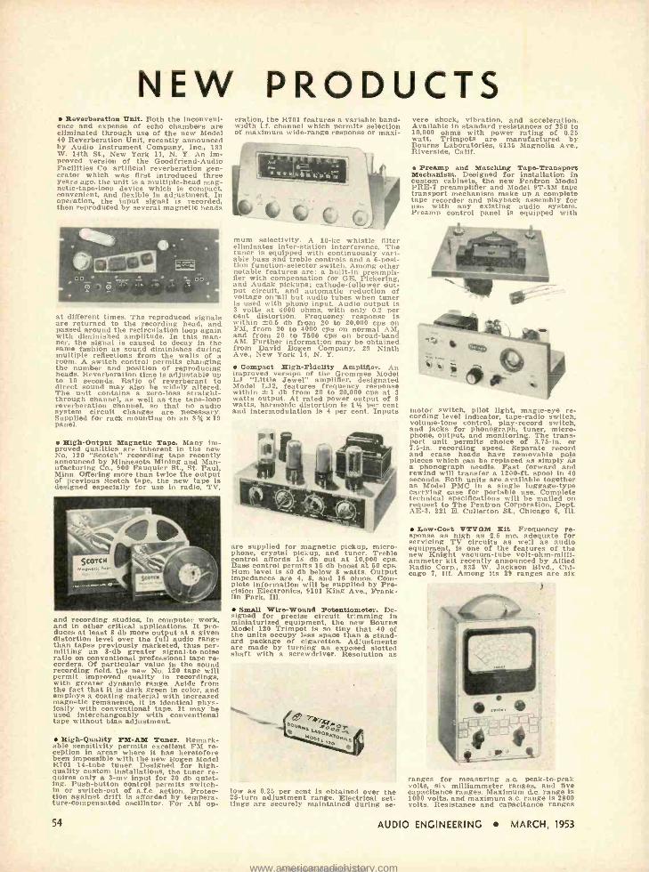
NEW PRODUCTS Reverberation Unit. Both the inconveni-
ence and expense of echo chambers are eliminated through use of the new Model 40 Reverberation Unit, recently announced by Audio Instrument Company, Inc., 133 W. 14th St., New York 11, N. Y. An im- proved version of the Goodfriend -Audio Facilities Co. artificial reverberation gen- erator which was first introduced three years ago, the unit is a multiple -head mag- netic- tape -loop device which is compact, convenient, and flexible in adjustment. In operation, the input signal is recorded, then reproduced by several magnetic heads
at different times. The reproduced signals are returned to the recording head, and passed around the recirculation loop again with diminished amplitude. In this man- ner, the signal is caused to decay in the same fashion as sound diminishes during multiple reflections from the walls of a room. A switch control permits changing the number and position of reproducing heads. Reverberation time is adjustable up to 10 seconds. Ratio of reverberant to direct sound may also be widely altered. The unit contains a zero -loss straight - through channel, as well as the tape -loop reverberation channel, so that no audio system circuit changes are necessary. Supplied for rack mounting on an 8% x 19 panel.
High -Output Magnetic Tape. Many im- proved qualities are inherent in the new No. 120 "Scotch" recording tape recently announced by Minnesota Mining and Man- ufacturing Co., 900 Fauquier St., St. Paul, Minn. Offering more than twice the output of previous Scotch tape, the new tape Is designed especially for use in radio, TV,
eration, the R701 features a variable band- width i.f. channel which permits selection of maximum wide -range response or maxi-
mum selectivity. A 10 -kc whistle filter eliminates inter -station interference. The tuner is equipped with continuously vari- able bass and treble controls and a 6 -posi- tion function -selector switch. Among other notable features are: a built -in preampli- fier with compensation for GE, Pickering, and Audak pickups; cathode -follower out- put circuit, and automatic reduction of voltage on all but audio tubes when tuner is used with phono input. Audio output is 3 volts at 6000 ohms, with only 0.2 per cent distortion. Frequency response is within ±0.5 db from 20 to 20,000 cps on FM, from 20 to 4000 cps on normal AM and from 20 to 7500 cps on broad -band AM. Further information may be obtained from David Bogen Company, 29 Ninth Ave., New York 14, N. Y.
Compact High- Pidelity Amplifier. An improved version of the Grommes Model LJ "Little Jewel" amplifier, designated Model LJ2, features frequency response within ± 1 db from 20 to 20,000 cps at 3 watts output. At rated power output of 8 watts, harmonic distortion is 1% per cent and intermodulation is 4 per cent. Inputs
and recording studios, in computer work, and in other critical applications. It pro- duces at least 8 db more output at a given distortion level over the full audio range than tapes previously marketed, thus per- mitting an 8 -db greater signal -to -noise ratio on conventional professional tape re- corders. Of particular value in the sound recording field, the new No. 120 tape will permit improved quality in recordings, with greater dynamic range. Aside from the fact that it is dark green in color, and employs a coating material with increased magnetic remanence, it is identical phys- ically with conventional tape. It may be used interchangeably with conventional tape without bias adjustment.
High- Quality PM -AM Tuner. Remark- able sensitivity permits excellent FM re- ception in areas where It has heretofore been impossible with the new Bogen Model R701 14 -tube tuner. Designed for high - quality custom installations, the tuner re- quires only a 3 -mv input for 30 db quiet- ing. Push- button control permits switch - in or switch -out of a.f.c. action. Protec- tion against drift is afforded by tempera- ture- compensated oscillator. For AM op-
54
are supplied for magnetic pickup, micro- phone, crystal pickup, and tuner. Treble control affords 18 db cut at 10,000 cps. Base control permits 15 db boost at 50 cps. Hum level is 80 db below 8 watts. Output impedances are 4, 8 and 16 ohms. Com- plete information will be supplied by Pre- cision Electronics, 9101 King Ave., Frank- lin Park, Ill.
Small Wire -Wound Potentiometer. De- signed for precise circuit trimming in miniaturized equipment, the new Bourns Model 120 Trimpot is so tiny that 40 of the units occupy less space than a stand- ard package of cigarettes. Adjustments are made by turning an exposed slotted shaft with a screwdriver. Resolution as
low as 0.25 per cent is obtained over the 25 -turn adjustment range. Electrical set- tings are securely maintained during se-
vere shock, vibration, and acceleration. Available in standard resistances of 250 to 10,000 ohms with power rating of 0.25 watt, Trimpots are manufactured by Bourns Laboratories, 6136 Magnolia Ave., Riverside, Calif.
Preamp and Matching Tape -Transport Mechanism. Designed for installation in custom cabinets, the new Pentron Model PRE -7 preamplifier and Model 9T -3M tape transport mechanism make up a complete tape recorder and playback assembly for use with any existing audio system. Preamp control panel is equipped with
motor switch, pilot light, magic -eye re- cording level indicator, tape -radio switch, volume -tone control, play record switch, and jacks for phonograph, tuner, micro- phone, output, and monitoring. The trans- port unit permits choice of 3.75 -in. or 7.5 -in. recording speed. Separate record and erase heads have removable pole pieces which can be replaced as simply as a phonograph needle. Fast forward and rewind will transfer a 1200 -fL spool in 40 seconds. Both units are available together as Model PMC in a single luggage -type carrying case for portable use. Complete technical specifications will be mailed on request to The Pentron Corporation, Dept. AE-3, 221 E. Cullerton St., Chicago 6, Ill.
Low -cost VTVOM Zit. Frequency re- sponse as high as 2.5 mc, adequate for servicing TV circuits as well as audio equipment, is one of the features of the new Knight vacuum -tube volt- ohm -milli- ammeter kit recently announced by Allied Radio Corp., 833 W. Jackson Blvd., Chi- cago 7, Ill. Among its 29 ranges are six
ranges for measuring a.c. peak -to -peak volte, six milliammeter ranges, and five capacitance ranges. Maximum d.c. range is 1000 volts, and maximum a.c. range is 2800 volte. Resistance and capacitance ranges
AUDIO ENGINEERING MARCH, 1953
www.americanradiohistory.comAmericanRadioHistory.Com

are 1000 megohms and 5000 microfarads, respectively. Special probes are available for extending the d.c. range to 30,000 volts and the a.c. frequency range to read r.f. to 200 mc. All voltage functions are elec- tronically protected against burnout.
Intercom Sytem. A baseboard- mounted power supply, self- compensating to de- liver required power to all or a selected group of stations, is featured with the new 20 -watt Redi -Power Talk -O- Phone, recently introduced by Talk -O -Phone Co., 1512 S. Pulaski Road, Chicago 23, Ill. Although retaining the compact size of
earlier models, the new Talk -O -Phone of- fers a number of additional engineering features. Uni -Trans dictation control elim- inates the need for operating any controls while dictating. Twelve, twenty, thirty, or forty station capacity can be housed in the same cabinet, and the system can be expanded or altered at any time without discarding the original equipment.
PM -AI[ Tuner. Newest in the line of high -fidelity components manufactured by The Pilot Radio Corporation, Long Island City, N. Y., is the Model AF -723 Pilotuner, an 8 -tube self -powered unit which incor- porates a temperature -compensated oscil- lator for drift -free FM reception, also a.f.c. which may be switched in or out at will.
Inputs are provided for TV and phono. Tone control on the AF -723 may be switched out when the tuner is used with an audio amplifier which incorporates such controle. Cathode -follower output permits up to 100 feet of interconnecting cable to amplifier without detracting from audio fidelity. The tuner is supplied with a hand- some bronze -finish escutcheon plate for custom cabinet installation. Over -all di- mensions are 14 x 7 Va x 81/2 in.
ERRATA
Olan E. Kruse, author of "Circle Di- agrams for Resistance- Capacitance -Cou- pled Amplifiers" in the February issue, ad- vises us of erroneous figures on his Fig. 3. The values for T along the top should have been: 1.59, 3.18, 4.77, 6.36, 7.95, 9.54, 11.1, 12.7, 14.3, and 15.9. The values for F along the left side of the diagram should have been : 100, 50.0, 33.3, 25.0, 20.0, 16.7, 14.3, 12.5, 11.1, and 10.0.
Lewis S. Goodfriend, author of "The Wide Range R -C Oscillator," also in the February issue, advises us that the top cathode resistor in Fig. 2 should have been 68 ohms, and that the lead between the junction of this resistor and the 2500 -ohm pot and the junction of R, and the 0.5 -pf capacitor should be a 1.0 -meg resistor rather than a solid wire. In Fig. 3, page 68, the top cathode resistor should have been 160 ohms, and the 1.0 -meg resistor should have been shown as described above in Fig. 2.
DESIGNED FOR HI -FI PERFECTION!
TANNOY 12 DUAL CONCENTRIC SPEAKER 130.00 net Internationally acclaimed for amazing response range, balance and definition, the Tannoy gives you uniform response from 35 to 25,000 cycles. Power capacity, 15 watts; Bass resonance, 35 cps; crossover frequency 1,700 cps.
15" speaker, 25 watt peak
GARRARD RC -80 RECORD CHANGER 41.45 net Less cartridge
The Garrard plays all three sizes (7 ", 10 ", 12 ") and all three speeds (33 -1 3, 45, 78 RPM)! Completely automatic, with
switch off at end of last record. Tone arm returns to rest position. Adaptable to either 110 or 220 V. Complete with 45 RPM spindle and two empty shells.
BOGEN R701 FM -AM TUNER I 145.20 net E, É- Full frequency range of 88 -108 MC on FM, 530 -1650 KC on AM; frequency response of 20- 20,000 cps. ±.5 db on FM; built in pre- amplifier, AFC, AFC defeat switch, low distortion; hum level - 65 db below. 1 4 tubes including power sup- ply. Size 15" 5 8 ' 2 " x 9 ' . Weight, 17 lbs.
159.00
CONCER.TONE 1501D TAPE RECORDER 345.00 net New and improved! Separate heads for high frequency erase, record and play back, with simultaneous monitor-
ing from tape while recording. Instantaneous choice of 7tí" or 15" per second tape speed. Three synchronous, dynamically balanced motors for dependable perform- ance. Frequency response ± 2 db, 50 to 15,000 cycles of 15" per second. Available in single or dual track. Carrying case and monitoring amplifier with 8 -in. speaker 82.50
BOGEN H010 -RXPX REMOTE CONTROL AMPLIFIER 147.15 The famous Bogen Baton combines an all -triode power amplifier and remote control. Power output 10 watts, peaks to 25; frequency response: ± 112 db, 10- 20,000 cps; Hum: 70 db below; speaker output: 12 ohms; 8 tubes; Inputs: GE, Pickering; tuner; Controls: bass, treble, power on -off, selector; size: 15" x 10" x 8"; weight: 32 lbs. Amplifier only 93.79 Remote control and pre -amplifier 53.36
tik
FAIRCHILD 215 SERIES CARTRIDGE 47.50 Here's unbelievable freedom from needle talk! Equipped with a dia -
mond stylus . . . the cartridge is of the moving coil design. 1.0 mil tip. 215C -3.0 mil tip 42.50 2158 -2.5 mil tip 42.50 For vertical records 50.00
Mail 8 Phone Orders Filled . . . 25% Deposit, Balance COD Send for FREE Catalogue, Music of the Masters
o 69 CORTLANDT ST., NEW YORK 7, N. Y.
r41ia Mit Dept. A 43
CORTLANDT 7- 0315 -9 The House Built on Service
AUDIO ENGINEERING MARCH, 1953 55
www.americanradiohistory.comAmericanRadioHistory.Com

OL
Plug -in Broadcast
PRE -AMPLIFIER á-
PLUG -IN DESIGN -simplifies maintenance. TWO STAGE -Ideal for microphone or transctip-
tiun pre- amplifier. EXCELLENT FREQUENCY RESPONSE - Features low
distortion and noise level. COMPACT...YET HIGHLY ACCESSIBLE.
The G -E Plug -in Broadcast Audio line includes: BA -1 -F BA -12 -C BP -10 -B
PRE -AMP PGM /MON AMP POWER SUPPLY
Por information write: General Electric Co., Section 4433, Electronics Park, Syracuse, N.Y.
GENERAL ELECTRIC
High Fidelity Record Reproduction
7, 10, AND 12 INCH RECORDS /4íG1/ 1l- %%thlifl4
3 -SPEED RECORD CHANGERS
MODEL 3 522' Intermixes 10 and 12-inch records LIST PRICE $65.00 ._ (less base)
tra MODEL 3/521' Non-Intermix Model LIST PRICE $54.50 (less base)
. 'Available in
1- cream, brown or gray finish.
56
RECORD CHANGER BASE Wood.
LIST Finish, heavy
COn$trUCilOn. LIST PRICE
On Sale at Leading Dealers. Write for Complete Literature
ROCKBAR CORPORATION 211 East 37th Street. New York 16, N.Y.
PATENTS "j
often synonymous!) into action. With high -quality audio going strong after the buildup in interest it has undergone since the war, many of us seem to be finding that the quality in the best audio amplifiers today leaves little to be desired and our- selves with little to do by way of improving it -except to try doing the same thing more cheaply. As audio has developed, we have built amplifiers with wider and wider fre- quency bands -up to 100 kc and more. In most cases the only value of such wideband response is in achieving better operation of the high -level feedback circuits and there is more than a suspicion that we have gone to such high- frequency response sometimes just through a desire to do "something more" even though the practical value is small.
Well, why not go the whole hog and start getting interested in video amplifica- tion? A video amplifier is essentially a resistance- coupled amplifier with extremely wide band -to at least 4 mc, generally, and sometimes a great deal more. As the word video indicates, the principal use for such amplifiers today is in amplifying television picture signals; but that is by no means the only use. Meantime, any good book on television will give the basic approach to wideband amplification, from which some audio might well jump off to new ap- proaches and better results than present circuits.
The apparatus required is simple enough -the same old tubes, resistors, capacitors, and the like. A couple of new components come into play-coils with small induct- ances, up to a maximum of around 1 milli- henry. They are easily wound or bought. Wideband oscilloscopes are available today, though they are a little expensive usually. But a long series of investigations, experi- mentation, and self -indoctrination can be had by playing with the family TV receiver. Better yet, get an old, second -hand receiver, derive signal from some convenient point in the good set (that won't harm it any way) and transmit video from the good set to the second -hand one via video amplifiers, attenuators, phase inverters, frequency -cor- rection networks, and all the rest of the possible gimmicks. Video work is just an extension of audio and it has the perfect field of play for the audio man with wide - banditis.
In future we are going to look for a few good video- amplifier patents. We'll write them up for Æ, see if Editor McProud will print them, then wait for the brickbats and bouquets in the mail!
(You're on your own, Mr. p. We'll run ern, b/d on your responsibility. En.)
AUDIO 1693 Li; oua page 25]
haft (m) of a small Hammer bone so that its head comes close to the Anvil which is part of the ring structure (ab).
4. To cause the diaphragm to have greater excursion, fasten a vessel (p) to the ring, and a funnel (y) to the ves- sel. The incoming sound will be carried to the diaphragm.
If one places the Anvil -forming ap- pendage between the teeth he will pos-
AUDIO ENGINEERING MARCH, 1953
www.americanradiohistory.comAmericanRadioHistory.Com
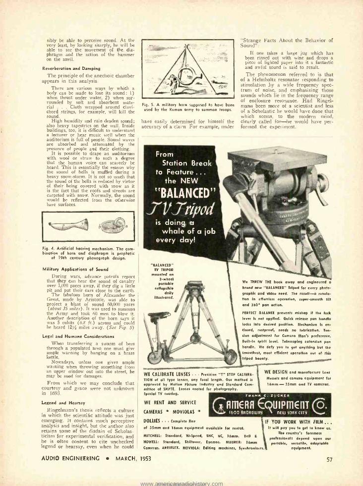
sibly be able to perceive sound. At the very least, by looking sharply, he will be able to see the movement of the. dia- phragm and the action of the hammer on the anvil.
Reverberation and Damping
The principle of the anechoic chambc; appears in this analysis.
There are various ways by which a body can be made to lose its sound: 1) when thrust under water, 2) when sur- rounded by soft and absorbent mate- rial . Cloth wrapped around clavi- chord strings, for example, will kill the sound.
High humidity and rain deaden sound; also heavy tapestries on the wall. Inside buildings, too, it is difficult to understand a lecturer or hear music well when the auditorium is full of people. Sound waves are absorbed and attenuated by the presence of people and their clothing.
It is possible to drape an auditorium with wool or straw to such a degree that the human voice can scarcely be heard. This is essentially the reason why the sound of bells is muffled during a heavy snow- storm. It is not so much that the sound of the bells is reduced by virtue of their being covered with snow as it is the fact that the roofs and streets are carpeted with snow. Normally, the sound would be reflected from the otherwise bare surfaces.
Fig. 4. Artificial hearing mechanism. The com- bination of horn and diaphragm is prophetic
of 19th century phonograph design.
Military Applications of Sound
During wars, advance patrols report that they can hear the sound of cavalry over 1,000 paces away, if they dig a little pit and put their ears close to the earth.
The fabulous horn of Alexander the Great, made by Aristotle, was able to project a blast of sound 60,000 paces (about 35 miles). It was used to summon
the Army and took 60 men to blow it. Another description of the horn says it was 5 cubits (6.8 ft.) across and could be heard 12% miles away. (See Fig. 5)
Legal and Humane Considerations
When transferring a swarm of bees through a populated area one must give ample warning by banging on a brass kettle.
Nowadays, unless one gives ample warning when throwing something from an upper window out into the street, he may be sued for damages. From which we may conclude that
courtesy and grace were not unknown in 1693.
Legend and Hearsay
Ringelmann's thesis reflects a culture in which the scientific attitude was just emerging. It contains much perceptive analysis and insight, but the author also retains some of the disdain of Scholas- ticism for experimental verification, and he is often content to cite unchecked legend or hearsay, even when he could
Fig. 5. A military horn supposed to have been used by the Roman army to summon troops.
have easily determined for himself the accuracy of a claim. For example, under
From Station Break
to Feature... the NEW
"Strange Facts About the Behavior of Sound":
If one takes a large jug which has been rinsed out with wine and drops a piece of lighted paper into it a fantastic and awful sound is said to result.
The phenomenon referred to is that of a Helmholtz resonator responding to stimulation by a wide frequency spec- trum of noise, and emphasizing those sounds which lie in the frequency range of enclosure resonance. Had Ringel- mann been more of a scientist and less of a Scholastic he would have done that which seems, to the modern mind, clearly called for -he would have per- formed the experiment.
is doing a whale of a job
every day!
"BALANCED" TV TRIPOD
mounted on 3 -wheel portable
collapsible dolly
Illustrated.
We THREW THE book away and engineered a
brand new "BALANCED" Tripod for every photo- graphic and video need. The result -a revela- tion in effortless operation, super- smooth tilt and 360° pan action.
PERFECT BALANCE prevents mishap if the lock
lever is not applied. Quick release pan handle locks into desired position. Mechanism is en-
closed, rustproof, needs no lubrication. Ten-
sion adjustment for Camera Man's preference. Built -in spirit level. Telescoping extension pan handle. We defy you to get anything but the smoothest, most efficient operation out of this tripod beauty.
WE CALIBRATE LENSES Precision "T" STOP CALIBRA-
TION of all type lenses, any focal length. Our method is
approved by Motion Picture Industry and Standard Com- mittee of SMPTE. Lenses coated for photography. Special TV coating.
WE RENT AND SERVICE
CAMERAS " MOVIOLAS `
DOLLIES Complete line
of 35mm and 16mm equipment available for rental.
WE DESIGN and manufacture Lens
Mounts and camera equipment for
16mm - 35mm and TV cameras.
FRANK C. ZUCKER
GAIllERR EQUIPmEf1TCD. 1600 BROROWAY 11EW 9ORH CITY
MITCHELL: Standard, Hi- Speed, BNC, NC, 16mm. Bell s
HOWELL: Standard, Shiftover, [yernos. MAURER: 16mm Cameras. ARRIFLEX. MOVIOLA: Editing machines, Synchronisers.
AUDIO ENGINEERING MARCH, 1953
IF YOU WORK WITH FILM .. .
It will pay you to get to know us.
The country's foremost professionals depend upon our portable, versatile, adaptable
equipment.
57
www.americanradiohistory.comAmericanRadioHistory.Com

1
WHY PAY RENT on your echo chamber?
Goodfriend -Audio Facilities Reverberation Unit now made exclusively in improved form by Audio Instrument Co., Inc.
AN ECHO CHAMBER ON AN 8.3í4't x 16" PANEL
Compact: Single 8 % "x 19" paneL Variable equalization: Built -in, for special effects. Reverberation time: Continuously adjustable. No pressure pads: Better tape motion, reduced head wear.
Delivery time: Six weeks.
Simulates reverberation of a room of any size, using a magnetic tape loop sys- tem with FIVE HEADS (Model 40) or SEVEN HEADS (Model 42). Switching heads produces various special effects, as
well as natural reverbera- tion.
Model 40: $985.00 Pays for it.clf in ; to S months.
INSTRUMENT
V v lde1.4. V COMPANY INC
OepI 1 3 3 WEST 14th STREET N Y 1I.N Y
Authoritative and Enlightening ...
Acknowledged the Leading Publication in the Field of Sound Reproduction
If you are novice, hobbyist, experimenter, or engineer... if you are a lover of music ... and in pursuit of sound, undistorted . . . Audio Engineering will be your faithful, reliable corn - panion all the way. You will find no more pleasureable and stimulating reading than there is in AE; absorbingly interest- ing material, valuable and authentic data, workable detailed in- structions ... all comprehensively and yet practically presented.
"What to Do" and "How to Do" will guide your every move through this thrilling experience we call Audio.
Each new issue brings New Ideas, New Slants, and Latest Devel- opments ... month in and month out ... twelve times a year.
BE SURE to get your copies REGULARLY.
MAIL this Coupon
NOW
AUDIO ENGINEERING P. O. Box 629. Mineola, N. Y. Enclosed is ] Check C Money Order ter $ Please send a opy of each now issue of Audio Engineering fee the neat [¡ 12 months; G 21 months to:
Please Print
Nome
Address
City Zeno State Subscription Price: U.£A.. C and Pen American Union: 1 year .
$3.00 2 years $3.00. Other countries: 1 year..$4.00 2 years..$7.00.
FIRST INVENTOR [from page 40]
ventor to discoveries disclosed in his application to which he had not made claim and that such discoveries were as a consequence, available to others.
"The question is, therefore, squarely presented," said that court, "whether on the issue of prior invention it is the claims or the disclosure which counts. On principle it would seem that the claims were the place to look for the invention. The disclosure, so far as it is only a description of the machine, process or composition, is certainly not the invention proper. It does not tell which of the various elements disclosed the patentee selects as the combination which it will be profitable to follow.
"Without some such selection the art is left without cue for omission and must reproduce the whole disclosure in all its details. The claims alone give any scope to the invention and some scope in essential to its value. It would seem that the 'invention' must lie in the act of selecting out of the possible combina- tions which will read upon the disclo- sure such as are new and useful.
"Therefore, at least presumptively, the 'invention' must be found in the claims and in the claims alone. If so, when the issue arises of prior invention between two persons, whether it be on interference or when raised by an in- fringer, it should be decided only by a comparison of the claims, i.e., of that part of the patent or application which sets out what combinations of the ele- ments disclosed the applicant says are his new and useful contributions to the art."
The discoverers of this process for acetylene welding appealed and the de- cision of the Federal District Court was affirmed by the Federal Circuit Court of Appeals, which stated,
"Thus the question is narrowed to this, does the 'first inventor' of the fourth defense signify one who describes patentable matter or one who both de- scribes and claims it. The question may be put thus, is mere disclosure (confi- dentially made to the Commissioner of Patents) and no more, in itself, suffi- cient evidence of invention? We think that it is not, for the reason that in the absence of an appropriate claim there is no evidence of the perfection of the mental concept which constitutes this intellectually a part of the invention.
"We hold that a 'first inventor' within the meaning of that phrase as used in the fourth defense, must be a person who perfects his invention. No inven- tion can be intellectually perfected un- less it is thought out and concluded and the only evidence of such perfected in- vention ordinarily derivable from any patent is a union of disclosure and claim."
When the appeal from this decision came before the United States Supreme Court a year and a half later the court
58 AUDIO ENGINEERING MARCH, 1953
www.americanradiohistory.comAmericanRadioHistory.Com

reversed the decision of the two lower courts on the opinion of Justice Holmes who established at that time the defini- tion of 'first inventor' that is now made a provision of the patent statute itself.
It is not disputed that the applica- tion gave a complete and adequate de- scription of the thing patented but did not claim it. The patent law authorizes a person who has invented an improve- ment like the present, 'not known or used by others in this country before invention' to obtain a patent for it.... The fundamental rule, we repeat, is that the patentee must be the first inventor."
REFERENCES
Detrola Radio & Television Corp. v. Hazel- tine Corp., 117 Fed. 2d 238: 313 U.S. 259
Hazeltine Corp. v. Abrams, 7 F. S. 908; 79 Fed. 2d 329
Davis -Bournonville Co. v. Alexander Mil- burn Co., 297 Fed. 846; 1 Fed. 2d 227; 270 U.S. 390
COLUMBIA "360" {frone page 29]
tances and locations. The resultant curves were integrated and then aver- aged to yield the one illustrated. Very close correlation can be found between the sound characteristic thus derived and the actual performance of the player in the home.
The amplifier has been designed to give adequate performance for a maxi- mum power output of about two watts, as shown in the distortion curves, Figs. 6 and 7. The amplifier frequency re- sponse has been shaped so that when combined with the other components of the system, the over -all sound pressure diagram is the desired one. Figure 8 shows the frequency response of the pickup by itself.
During the development of the Colum- bia "360" in the CBS Laboratories Divi- sion we had to rely on the support and inspiration of many. In particular, the writer is indebted to Thomas Broderick, Richard Mahler and René Snepvangers for their wholehearted cooperation and many useful suggestions.
EIIi1' II9 Ill .tarh "'1"'IIIÏ4III P,Alll
.SIIIIICIIlI i10III Ilill III EI 111
Fig. 8. Typical response plotted against the electrical curve of Columbia 103 test record.
REEVES APPOINTS NEELY
Products of Reeves Soundcraft Corpo- ration, New York, will be distributed to the electronics industry in the Southwest by Neely Enterprises, Inc., Los Angeles, effective at once, according to Frank B. Rogers, Jr., Reeves vice -president.
Vemeadioptai Sciage? RESEARCH
DEVELOPMENT SERVICE
on
Diamond` Sapphenoí& Sapphire° for
Acetate Disc - Sapphire Cutters Magnetic Film - Diamond Scribers Magnetic Tape - Sapphenoid Guides
To Your Specifications
Veacoaatic ,eC'aeonatanv S,nco 1553
P. 0. Box "P" Phone STate 4 -0881
Encino, California
qeatk/'t AMPLIFIER KIT
FEATURES Practically distantness. Harm,mc and letermaduI*Ian distortion nth less than /ea hall 111ió at 5 watts. Frequecy response f- I dh Irem 11 cycles to IA kilocycles. Altec Lensiq PEERLESS or ACROSOUND Transformers available. First Willmar type Ampller suppled with molding preamplber.
When selecting an amplifier for the heart of a fine high- ` fidelity audio system, investigate the outstanding advantages
offered by the Heathkit Williamson type Amplifier. Here is an amplifier that meets every high -fidelity audio require-
. ment and makes listening to recorded music a thrilling new experience through naturally clear, lifelike reproduction of sound at all tonal levels. Wide acceptance of the Heathkit
.. Williamson type Amplifier by the most critical purchasers clearly demonstrates that high -fidelity can be coupled with low cost. For factual information regarding the Heathkit
' Williamson type Amplifier. consult "CONSUMERS RE- SEARCH ANNUAL CUMULATIVE BULLETIN 1952 -53."
This outstanding amplifier is offered with the optional choice of the ACROSOUND output transformer or the PEER- LESS output transformer. ACROSOUND features ULTRA. LINEAR circuitry, which is the exclusive development of the Acro Products Company and provides a.greater margin of reserve power efficiency and increases power output. PEER- LESS features additional primary taps to permit the optional choice of either the extended power circuitry. now enjoying current popularity, or all of the advantages of the original Williamson type circuit.
The construction manual has been simplified to the point where even the complete novice can successfully construct the amplifier without difficulty. Write for a tree catalogue containing complete specifications and schematics of the Heathkit Williamson type Amplifier.
S O N T Y P E
HEATH COMPANY BENTON HARBOR 25, MICH.
PRICES OF VARIOUS COMBINATIONS W.2 Amplifier Kit Ilnel. Main Amplifler .. dh Peerless Output Transform-
. Power Supply and WA -PI 6950 Preamplifier Kit) Shipping f A
Weight 39 lbs. Shipped express n iy.
1.10-2M h Peerless Output
Main erAmplifl. m,, rower Supply) Shipping $ 15 \V..ight 29 Iba. Shipped express T ::IY.
W.3 Amplifier Kit lined. Main Amplifier ..VIh Acrosound Output Trana-
Power Supply and WA-
$ hteampllfler Kit) Shipping
Height 39 lb, Shipped press
W -3M Amplifier Kit tlnrl. Main Amplifier foith Aerosound Output Trans. Ii rmer and Power Supply) Ship-
ping Weight 29 lbs, Shipped f e
presa only. WA -Pa Preamplifier Nit only. Shipping Weight 7 lbs. Shipped express ur parcel post.
$1g>s
AUDIO ENGINEERING MARCH, 1953 59
4
www.americanradiohistory.comAmericanRadioHistory.Com
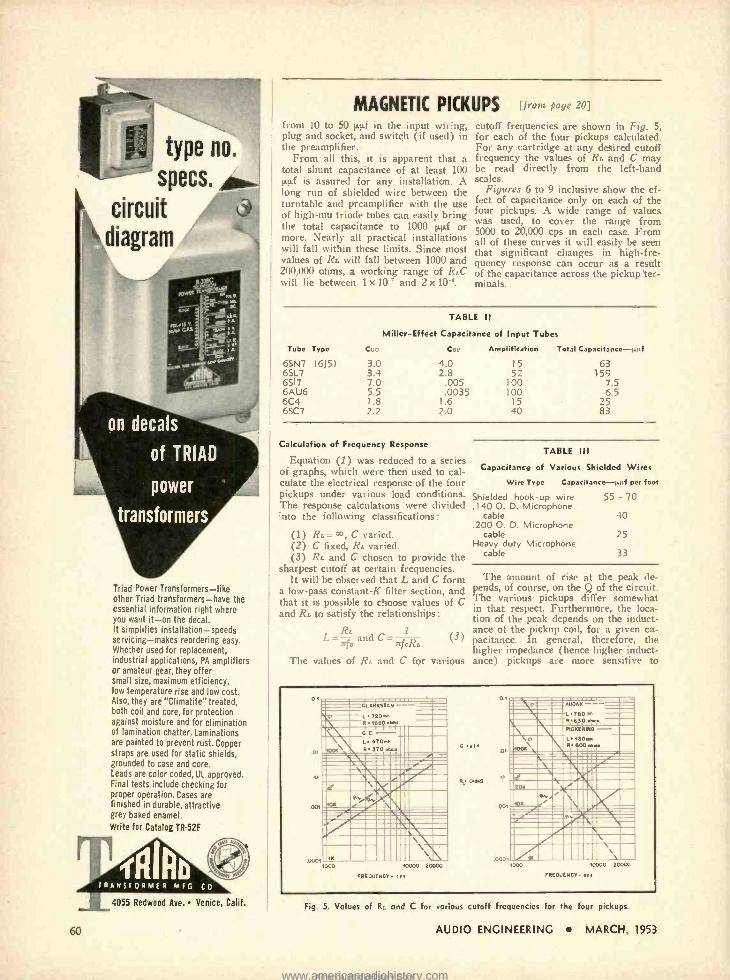
type no.
specs.
circuit t' diagram
Triad Power Transformers -like other Triad transformers -have the essential information right where you want it -on the decal. It simplifies installation- speeds servicing -makes reordering easy. Whether used for replacement, industrial applications, PA amplifiers or amateur gear, they offer small size, maximum efficiency, low temperature rise and low cost. Also, they are "Climatite" treated, both coil and core, for protection against moisture and for elimination of lamination chatter. Laminations are painted to prevent rust. Copper straps are used for static shields, grounded to case and core. Leads are color coded, UL approved. Final tests include checking for proper operation. Cases are finished in durable, attractive grey baked enamel.
Write for Catalog TR-52F
60
4055 Redwood Ave. Venice, Calif.
MAGNETIC PICKUPS [from page 20]
from 10 to 50 iii in the input wiring, plug and socket, and switch (if used) in the preamplifier.
From all this, it is apparent that a total shunt capacitance of at least 100 p.p.f is assured for any installation. A long run of shielded wire between the turntable and preamplifier with the use of high -mu triode tubes can easily bring the total capacitance to 1000 p.p,f or more. Nearly all practical installations will fall within these limits. Since most values of RL will fall between 1000 and 200.000 ohms, a working range of RLC will lie between 1 x 10' and 2 x 10.
cutoff frequencies are shown in Fig. 5, for each of the four pickups calculated. For any cartridge at any desired cutoff frequency the values of RL and C may be read directly from the left -hand scales.
Figures 6 to 9 inclusive show the ef- fect of capacitance only on each of the four pickups. A wide range of values was used, to cover the range from 5000 to 20,000 cps in each case. From all of these curves it will easily be seen that significant changes in high -fre- quency response can occur as a result of the capacitance across the pickup ter- minals.
TABLE II
Miller- Effect Capacitance of Input Tubes
Tube Type C: G:. Amplification Total Capacitance -µµf 6SN7 (6J5) 3.0 4.0 15 63 6SL7 3.4 2.8 52 159 6517 7.0 .005 100 7.5 6AU6 5.5 .0035 100 6.5 6C4 1.8 1.6 15 25 6SC7 2.2 2.0 40 83
Calculation of Frequency Response
Equation (1) was reduced to a series of graphs, which were then used to cal- culate the electrical response of the four pickups under various load conditions. The response calculations were divided into the following classifications:
(1) RL= 00, C varied. (2) C fixed, RL varied. (3) RL and C chosen to provide the
sharpest cutoff at certain frequencies. It will be observed that L and C form
a low -pass constant -K filter section, and that it is possible to choose values of C and RL to satisfy the relationships :
afe and C =afcRL (3)
The values of R1. and C for various
TABLE Ill
Capacitance of Various Shielded Wires
Wire Type Capacitance-out per foot
Shielded hook -up wire .140 0. D. Microphone
cable .200 0. D. Microphone
cable Heavy duty Microphone
cable
55 -70
40
25
33
The amount of rise at the peak de- pends, of course, on the Q of the circuit. The various pickups differ somewhat in that respect. Furthermore, the loca- tion of the peak depends on the induct- ance of the pickup coil, for a given ca- pacitance. In general, therefore, the higher impedance (hence higher induct- ance) pickups are more sensitive to
0.1
01
001
_ CLARRST6N--- Nç ti_ L 720.. R1660....
LW 4 E. - II I, íLis7o«..II- .i_mC::'.'. 01.1M111IMM, 11
"JI!: ......mone. 1,01M11/aIM; \ \ lR
1000 10000 20000
FREQUENCY
C ..16
0.1
01
001
00011000
== auoaR --- 0760.. 6__m Z_,_- R630.... IIMM PICKERING - I. ñwoo«.. oo .=:=E : :..:::JI 11111MrMMwc IF,=tellIN 'it7B1
Iaii 1 __ \ I1 MIMI IIIIIMIIIIII11111III II 1111111111
10000 20000
FREQUENCY -...
Fig. 5. Values of R,. and C for various cutoff frequencies for the four pickups.
AUDIO ENGINEERING MARCH, 1953
www.americanradiohistory.comAmericanRadioHistory.Com

shunt capacitance effects than are the lower impedance units.
In the very- high- impedance units, particular care should be taken to re- duce shunt capacitance, since even 100 or 200 µµf will have a significant effect on the response above 10,000 cps.
The addition of a shunt resistance makes it possible to flatten out the reso- nance peak, but it is not possible to ob-
+10 100VVf
00 °<
_i /91 _/,r1't _. ii ii
®1 n, '. ',' AUDAK RL. o
foo
FREQUENCY - cps
10000 20000
Fig. 6. Response of Audak L -6 pickup with various shunt capacitances and a resistive
load of
tain any significant response above the cutoff frequency.
Figures 10, 11, 12 and 13 show the ef- fects of adding resistance in parallel with the shunt capacitance. It is appar- ent that a value of resistance can be found to give substantially flat response out to the cutoff frequency, but the up- per frequency limit is definitely fixed by the product of coil inductance and shunt capacitance.
When the values of RL and C satisfy the relationships expressed by Eqs. (3) and plotted in Fig. 5, a low -pass con stant -K filter network results. To indi- cate the kind of result to he expected with each of the four pickups, Fig. 14
á
+10
o
> -10 a
á -2
.0002 pf
0001pf
Al _
4.
O.E. CARTR DOE
Ru.m I
1000
FREQUENCY - cps
10000 20000
Fig. 7. Response of GE RPX -050 pickup with various shunt capacitances. R,.= .
ß Built for the
BROADCASTER w 1 b Here at last is a magnetic tape recorder specifically designed to meet all the re- quirements of broadcast, recording and in-
dustrial engineers -the Concertone NWR -1.
The Concertone NWR -1 incorporates ad-
vances in engineering and performance found in no other tape recorder: Automatic brake system needs no adjustment. Direct drive from dual speed hysteresis synchron- ous motor Accommodates up to 5 heads
Suitable for rack panel installation or portable cases May be serviced during operation Full pushbutton remote control
Accepts up to NAB size reels without adapters Metering of input, output and .
bias levels.
Write for Bulletin 300 1111111\ Manufactured by
Berlant Associates 1917 W. Jefferson Blvd . Los Angeles 16, Calif.
l>
ANNOUNCES Grand Opening New York's
Largest Audio Center
650 Sixth Avenue FEATURING
NOT 1 ... NOT 2 ... BUT 3
Complete SOUND STUDIOS ( rg
AUDIO ENGINEERING MARCH, 1953
* Conveniently located for easy access from any part of Metropolitan New York * Staffed
your qualified u personnel to help
solve * The most complete display of all finest makes of audio equipment * Visit us today and see why Sun Radio sets the standards for the audio industry * Get your free copy of Sun's 1953 Audio Equipment handbook. 100 of the most valuable pages any music lover could have
& E L E C T R O N I C S CO.
650 Sixth Ave. at corner of 20th St., New York, N. Y. ORegon 5 -8600 Open Dily & Saturday 8:30 -6:00
61
www.americanradiohistory.comAmericanRadioHistory.Com

The Famous Baruch -Lang HIGH FIDELITY
SPEAKER SYSTEM 4 SPECIALLY DESIGNED
.., SPEAKERS, COMPLETE . .
WITH CABINET
$29.9áa, Hi -FI {
Model 501 -- ßíw Compact.. highfidelity corner speaker system, developed at the famous Mass. Institute of Technology. Baruch- Lang principals approach acoustical qualities of larger units costing four times this low price. Small space requirements, high output and wide dispersion angle. make it perfect for low cost, high Adel ity music systems In homes. public buildings. restaurants. schools. Con- nects easily to phono systems. FM -AM radios. TV. Response: 40 to 12.000 cps at plus or minus 3 db. 13" high. 19" wide. 9'," deep Wt. ten lbs. 4 ohms impedance.
Brilliant New Hi- Fidelity!
PILOT FM -AM TUNER Self -contained p
_' ply. With tout flat position. audio I'- quency response Ls w p111, min* 2 db. M... 1:11:011
din ' ' ....I audio output
is O 6 $99Á5P
-E2. 1
PILOTONE AMPLIFIER Model AA902 $42.50 PILOTONE AMPLIFIER Model AA901 399.50 PILOTONE PREAMPLIFIER Model PA911 $29.95
The Last Word In High Fidelity
BROOK AMPLIFIERS Low mu triodes for 12A4 be,t tonal quality. Re- 10 W. mote control pre -amp amp i -.
has inputs for tuner, pro -amp TV and phono; ore t, single chassis units. 8 ;222 position stepped bass and treble control dr- -` cults. Frequency re- sponse: 15 to 30,000 _j cycles.
G. E. Variable Reluctance
CARTRIDGES GE RPX -050 dual reversible sapphire stylus 8.37 (:E RPX -051 Same as RPX 050 (less stylus) 5.28 GE SPX -052 Combination diamond and sapphire
stylos 23.37 GE RPX -040 with .003 sapphire 5.97 GE RPX -041 with .001 sapphire 5.97 GE RPX -0422 (less stylus) 4.35 GE RPX -046 Professional type (less stylus) 6.87 GE HI'X 047 Itroadrast type (less stylist 9.27
ACRO TRANSFORMERS All Models fully potted
TO -300 for ultra linear 324.75 TO -290 .... 15.75 TO.270 11.75 TO-310 .... 18.75 TO -260 11.75 TO -380 .... 14.50 TO -250 11.75
Address Orders To Dept. AE 3 Write For FREE Booklet "Hi -Fi Magic"
WHOLESALE RADIO PARTS CO., Inc.
311 W. Baltimore SP.
BALTIMORE 1, MD.
62
+10
.001Yf
,SVf y
OOV 200rr1
W.,s
è. 100r1d I bl
I120M
, PICKERING -
RL Im I
1000
FREQUENCY- cps
10000 s000o
Fig. 8. Response of Pickering D120M pickup with various shunt capacitances. R1,= r.
was prepared, using values selected from Fig. 5 for a cutoff frequency of 5000 cps. As might be expected, the sharpness of cutoff varies from unit to unit according to the Q of the coil. This Q cannot completely be represented by
Rwhere L is the coil inductance and
R the coil and lead resistance. The ac- tual Q depends on the a.c. losses (eddy currents, hysteresis, etc. in the soft -iron magnetic structures in the pickup) as well as the d.c. resistances. However, it was found that in devices of the type being discussed here, the discrepancy between calculated and measured re- sponse was less than the probable error of measurement.
To indicate what can be done with the cut -off filter effect, a single pickup was provided with four different sets of terminating R-C combinations selected from Fig. 5; Fig. 15 shows the results for 3000 -, 5000 -, 7000 -, and 10,000 -cps cutoff frequencies. It will be seen that
+10
AUDAK - WITH
1
L -8 002
i
CAPACITANCE
I I I I l l
1111
--_-_-Aa1 ,, io
R
-
1 NO RES STANCE
2 50000 OHMS 3.20000 OHMS
4 +10000 OHMS
1000
FREQUENCY - cps
'10000 20000
+10
o
-30
200 w JAIMIG2
.
ii , 100r
i: vf
: b1.
1II\A III1g-
I Ill CLARKSTAN
RL o I
FREQUENCY- epa
10000 30000
Fig. 9. Response of Clarkston pickup with various shunt capacitances. R. = 00
the rate of attenuation above cutoff is very close to 12 db per octave.
In order to check the equations which were used to obtain the foregoing re- sponse curves, actual measurements were made by two methods: the pickups were tested on a standard frequency record, and they were also checked by the simulated- signal method. The meas- urements made with the frequency rec- ord gave close agreement up to 10,000 cps, and increasing spread, of a random nature, above that frequency. This is to be expected because of the high prob- able error in this method of measure- ment discussed earlier.
The second method gave complete agreement between measured and cal- culated results. The circuit of Fig. 16 was used.
Conclusion
It is evident that the load impedance across the terminals of a magnetic pho- nograph pickup will have a great effect
+10
o
10
20
-30
CLARKSTAN 1
AI`: __
ek \,
N RE IISTI E
2 100000 OHMS
-3 50000 OHMS
4 20000 OHMS
5 10000 OHMS
I
1000
FREQUENCY cp
10000 20000
Fig. 10. Response of Audak L -6 pickup with Fig. 11. Response of Clarkston pickup with shunt capacitance of .002 µf and various load shunt capacitance of .002 µf and various load
resistances. resistances.
AUDIO ENGINEERING MARCH, 1953
www.americanradiohistory.comAmericanRadioHistory.Com

+10
0
- 10
- 20
G.E.
Ai/ 2 II . 1`
- 4 II\ T in _
2 100000 OHMS
_ 3 50000 OHMS
4 200000HMS' - 5 10000 OHMS.
1 I I
1000
FREQUENCY -spc
10000
Fig. 12. Response of GE RPX -050 pickup with shunt capacitance of .002 Itf and various load
resistances.
1.10
o
- 10
- 20
PICKERING
1
AA -'á ii R I- -1 NO RESISTANCE 2 30000 OHMS
'OHMS -3 115000 4 5000 'OHM'S
5 3000 OHMS
I I I
1000
FREQUENCY- cep
10000
Fig. 13. Response of Pickering D12OM pickup with shunt capacitance of .005 ttf and vari-
ous load resistances.
eMe.,...
5KC CUTOFF R, C
-- CLARKSTAN 23000 .001401 ----- AUDAK 25000 .0013p1-
PICKERING 9700 .00670 -s- G E. 15000 .0022p1-
I I l l 11111
FREQUENCY - cps
1000 20000
00
Fig. 14. Curves showing 5000 -cps cutoff with the four pickups when shunted by resistors
and capacitors shown in the legend.
G.E. CARTRIDGE
- CUTOFF FILTERS
INIO
1 3KC 9000
2 SKC 15000 - 3 7KC 21000 4 10KC 29000
.006
.0022
.0011
.00054
1000
FREQUENCY - cps
10000 20000
Fig. 15. Curves showing low -pass filter effect on response of GE RPX -050 pickup when shunted with capacitances and resistances
indicated.
on the frequency response of the device. This effect can be accurately calculated for a given pickup of known coil resist- ance and inductance. A resistive termi- nation causes a general drop in output at all frequencies, the loss increasing at high frequencies. A capacitive termina- tion causes a peak at a frequency deter- mined by the LC product, of a magni- tude depending on the Q of the circuit. A combination of resistance and capaci- tance will modify the peak, and at one specific set of values for each case will constitute a constant -K low -pass filter. When the resistive shunt has a low value compared to the capacitive react- ance, the effect approaches that obtained with resistance termination alone.
The foregoing information can be used to guard against unwanted modifi- cations of the pickup frequency re- sponse, to determine the highest usable frequency obtainable under a given set of conditions, to compensate for fre- quency effects in other parts of the sys- tem, and to reduce noise from records by using the low -pass filter effect.
Fig. 16. Connection of equipment to obtain response curves shown. Values observed check with those obtained from frequency records.
REK -O -KUT FIRE
Serious damage by fire was suffered by the Rek -O -Kut Company, manufacturer of precision turntables, Long Island City, N. Y. on the night of January 31. Although production was entirely disrupted for a short time, the plant was back in opera- tion within a matter of days, and is now functioning on a virtually normal schedule.
AUDIO ENGINEERING MARCH, 1953
For as little as $20 and no more than $120, your Hi -Fi system can include the
EXPONENTIAL Acoustical Labyrinth
er mid -frequency res ònse. No more "Looms- and "thc.mps" of ordinary enclosures. Your boss re- sponse eoctended downward an oc- tave.That's al yours IF your p esent speaker is a high- fidelity coa:cìcI type and IF you anclose it in the superb Acoustical labyrinth. For complete technical de'ails, see your deder or
LABYRINTH AND CABINET, 11ess
speaker) in mahogany or blonds oak, 6120
KIT ONLY RL -4.35, to assemble your own Labyrinth with your own speaker $ 2Ó
17 -inch Coaxial Speaker. $49.95
15 -inch Coaxial Speaker. $179.95
STROMBERG- CARLSON Sound Division
1219 1.1.11 FORD :13t.. Iö11:11F:±1 1:II 3. \.1.
63
www.americanradiohistory.comAmericanRadioHistory.Com

GROMMES AMPLIFIERS
Model 50 PG .....,...,t ..a...__.....r.: :..:PP::+..a,.. .b.,a..m l'.0 1>.40r..
AMPERITE Studio Microphones
Et P.A. Prices
Ideal fo- ItOADCISTIN6 IICU]INi IIBLIE AIDIESS 'Tie uhietc in micro - plonc qu31,y," says Ewan 2nlirq, round engines of -he Hotel Now kskor.
5ho r. rilh into the r ew ATpe rite Micro- ph sne-c r :ford2 feel away- -.pottudion is
&Ways p.1ct. No. ,Nectod by
ory clisotc cnuiions. SusonHe! t. with-
Hold ereee' kn scking around."
Models r281.3 -200 ohms 2BNG -Hi -imp.
List $4.00
"Kortok" Mikes Model SKH, list $12.00 Model KKH, list $18.00
Special' Write for Special Introductory Off.r,
Offer: and 4-paye illustrated
AMPER /TE Gmpany lnc. 561 BROACWAY NEW YORK 12. N. Y.
Corrado. Atlas Radio Corp., .td., 560 King St. W., Toronto
Model 215BA
15 Wort '
ALL TRIODE BASIC AMPLIFIER Retpon.e 1 200 00,900 CPI. P.I. a pawar 21 wan.. Onlortiom ate and .2% alarm
$ 0 0 5 0 botk Wen Imp- 2 dirM touP4d stapes,
tahode tolla..n. drv.n.
WRITE FOR CATALOG
&to, PRECISION ELECTRONICS, Inc. 9.01 King Avenue, Franklin Park, 111.
64
THEATER SOUND from page 31
Design of the Main Case
The surest way to cut and assemble the sections of the wood cabinet without mistakes is to make a plan drawing of its assembly to scale, similar to Fig. 7 or 8. This is especially true if the plywood is of different thicknesses. In the cabinets we constructed we used %- in. plywood throughout, but the front of the cabinet, sides, top, and bottom could be made of thicker plywood if it is on hand. All pieces must be at least %-in. thick, however.
Figure 9 shows the metal horn at- tached to the front by wood screws but this was our first assembly. In later models, the fin -like separator pieces pro- ject at right angles from the center of each side of the sheet metal horn, to act as struts between partitions, and they are slotted across one side to let the 3 /16 -in. truss rods pass through them. These pieces must be shaped to fairly well match the surfaces they are to push against, and to obtain a snug fit so that partitions will not be sprung out of position as truss rods are tightened.
A truss rod passes from the side of the sheet metal horn to the outside of the cabinet in each of the four directions, at the center of the sound passages. After partitions for folded horn sound pass- ages have been cut and shaped to fit together correctly, these fin -like sepa- rators must be lined up with the direc- tion of sound and tacked in place with small brads. As the horn partitions are assembled, a 3 /16 -in. rod (such as steel welding rod) can be threaded through the group to help line up the separators while they are tacked in place.
Finally each truss rod may be cut to length and threaded on each end. Screw a nut on one end with a thread or so sticking through; clamp the rod in the vise with the nut resting on the jaws; and rivet the end with a ball peen ham- mer. This end is used at the outside of the cabinet with a large washer to keep the nut from seating into the wood with the vibrations. The other nut is screwed on the end which sticks into the sheet metal horn, with a good lock washer to keep it from working loose. Allow plenty of thread on this end for tightening.
In installing an 8 -in. speaker frame on the larger magnet an additional 16- ga. metal flange can be included in the assembly, as shown in Fig. 7, to form a tie or hub for the partitions of the sound chamber. This member seals off the passage of sound to the rear and gives a more direct support for the heavy magnet. With our first woofer we used a wooden collar, fabricated by glueing two layers of -in. plywood together, as shown in Fig. 8. One layer was given % -in. slots to let a 3 /16 -in. tie rod pass through on each side of the speaker magnet.
Strike back
Your gifts to the American Cancer Society help guard those
you love.
Your dollars support research in
a hundred laboratories and univer-
sities ... spread life -saving infor-
mation ... ease pain and suffering
...provide facilities for treatment
and care of cancer patients.
It is a sobering fact that cancer
may strike anyone tomorrow:
strike back today with a gift to
the American Cancer Society.
You may mail it, simply ad-
dressed CANCER, do your local
post office.
American
Cancer
Society
AUDIO ENGINEERING MARCH, 1953
www.americanradiohistory.comAmericanRadioHistory.Com

Where the metal horn fits through the front panel and where the partitions were fit to the wooden collar around the speaker, a thin layer of plastic (non- hardening) putty was applied between surfaces. This was to seal from passage of air and to prevent any spurious vi- brations at joints.
No. 8 wood screws, of different lengths, were used in our first cabinet. Lengths were chosen so that 1 in. or more of thread was seated in the holding member and they were spaced 1/ in. apart in short runs and 2/ or 3 in. along the main sides. A small hole was drilled to guide each screw and prevent splitting of edges of panels. Then the hole through the held piece was enlarged for the shank and countersunk. A bit of floor wax was used to ease each screw home in its long run.
Arranging Inner Passages
In computing the sound passage area past the speaker mounting flange, the cross sectional area between partitions, at A in Fig. 7, is figured and the cir- cular area of the speaker flange de- ducted. It will be seen that the sound waves have to turn a 90 -deg. angle at the space marked A before departing from this chamber back of the mounting ring. Thus frequencies of the intermedi- ate range are filtered out by acoustical resistance before they can cause much distortion in the folded horn passages.
Continuing along the inner sound passages, the cross sectional area at each change of direction is figured for doubling every 12 in. in axial length. Since there is no continuous 12 -in. run in any part of it, this can only be a rough approximation, by proportions. Remember to allow for the same degree of expansion as the sound bends around the end of partitions because it may travel four or five inches axially in these bends. Leaving the sound chamber at A, the low notes pass toward the front of the cabinet and are bent back at B to pass rearward along the top and bottom panels to C.
Many corner speaker cabinets de- pend on the walls of the room to form the final folded passage, but this design uses complete side panels with the truss rods terminating in them. Pieces of %- in. hair felt were glued along the out- side of these panels to prevent their making vibrating contact with walls of the room. Rubber feet were installed on the bottom. Thus, there is practically no sound transmission through the room walls at normal operating levels.
Curved inserts of sheet metal were bolted to the side walls and center sep- arator to help the sound around the last bend at C and prevent possible distor- tion in this large chamber which sur- rounds the magnet. This sheet metal may be any gauge from 28 to 22, for easy shaping. Use lock washers on all bolts, which are 8 -32 machine screws in most locations.
AUDIO ENGINEERING MARCH,
Before tightening the truss rod nuts in the metal horn, on the final assembly, twist a turn of small wire under each nut and allow the two ends to reach out the front like hairpins. Then take an old gauze or lace curtain and wad it up and pack it loosely in the horn to fill it almost to the mouth. Place a piece of light hardware cloth over this curtain and secure in place with these hair pins. If the hardware cloth is not light and pliable, its ends may receive vibrations from touching the metal horn.
The purpose of this curtain wad is twofold. Naturally, the direct radiated sound is much more effective than the lower notes which have to traverse the folded horn. So this material acts as a mute to cut down the intensity of the emerging notes and provide a distortion - free coupling with the outside air. Thus a fair balance can be obtained between the two horns and further experiment- ing may be resorted to in order to suit the needs of the particular speaker and horn assembly.
Don't be too concerned about the looks of the sheet metal horn or other features around that part of the cabinet because it will have to be covered with some cloth or other finishing. Picture molding was used to form open louvers over the horn on our first cabinet. There are many ways to dress up this cabinet to fit in with the surrounding environ- ment. Do not run any wide molding up the edge of the horn opening against the wall at D, Figs. 7 and 8. Any mold- ing which extends into this opening from thé wall would curtail the annular movement of the lowest notes along this outer wall.
Like most experimenters, we have never gotten around to finishing our cabinet because we are too busy on other projects. Louvers should not be used over the tweeter and any cloth used over its opening should be of fairly loose weave and hard, wiry thread, preferably plastic.
Both the tweeter and the center horn must be mounted flush with the front surface of the panel (disregarding louvers which extend beyond). The reason for this is, of course, to avoid any discontinuities in the sound path where the horn joins the open air.
Sounds like a lot of work, doesn't it? It has taken years of struggling to achieve this ideal and the real listening satisfaction for a true music fanatic. Let's put it this way: A sextet of saxo- phones of different ranges can imitate the brass choir, but the comparison in texture is about the same as comparing an ordinary 12- or 15 -in. resonator - boxed speaker with our system -except that the saxophones are a little muddier than the box speaker.
In the final article of this series, we will discuss the controls that go with the dividing network.
[To be concluded]
1953
0000000000000 o RADIO -ELECTRONICS 00
A Preview of Progress
I.R.E. CONVENTION 00000000.0000
RADIO ENGINEERING SHOW
405 EXHIBITS
WALD ORF -A S70RIA'NOTEL GRANO CENTRAL PALACE
NEW YORK CITY
MARCH 23 26 1953
o o
o
COME AGAIN - AUDIO MEN!
Welcome to the Radio Engineer- ing Show-
March 23- 26,1953 at New York City
19 IRE Professional Groups have prepared skillfully organized sym- posia and technical sessions on all phases of radio, TV, and electron- ics. These papers will keep you up- to-the- minute on the develop- ments which are to come in the next few years -for the IRE Con- vention Theme is:
Radio -Electronics "A Preview of Progress"
The colorful Annual Meeting on Monday at 10 (opening morn- ing) will feature the "Founders' Award ". Social Events include the "Get Together Cocktail Party" Monday, and the Annual Banquet Wednesday, all at the Waldorf Astoria Hotel.
405 Exhibitors are using 58,680 square feet -the entire four floors of Grand Central Palace, to gist. you a "Preview of Progress" in the apparatus, components and instruments of Radio-Electronics. Registration: IRE Members $1.00 Non -Members $3.00. Register at Grand Central Palace, 47th & Lex- ington Avenue, or The Waldorf Astoria Hotel, 49th & Lexington Avenue, New York City.
THE INSTITUTE OF RADIO ENGINEERS
65
www.americanradiohistory.comAmericanRadioHistory.Com

It's no trick! No talent or training needed to splice any type of safety film, - . -
forever, the new, elec- tric "butt- welded" mir- acle device does it AUTOMATICALLY!
Prestoseal splices magnetic film permanently
in 10 seconds!
J
r . replasticized! Eliminates dis-
tortion, drying out, no overlap or double thickness, no cement, brushes or scraping. Guarantees perfect frame alignment. No lights required.
Brochure on request
PRESTOSEAL ORP.
3727 33rd st., Long Island City 1, L.I.
EVERYTHING IN AUDIO! HUDSON RADIO a TELEVISION CENT.
Largest Selection of ALL Standard Elec- tronic and High -Fidelity Equipment. Ultra- Modern Audio Comparison Sound Studios
LOWEST PRICES FINEST SERVICE
NEEke ' 1953 Newest Most Complete
HUDSON CATALOG
1M1.,. .ti
Over 196 pages .
value -packed with the world's finest Radio, TV and Electronic Equip- ment. High -Fidelity and PA Sound Equipment - . -
Amplifiers, Speakers, Tu- ners, Record Changers, Recorders, Packaged Systems, Custom Furni- ture, etc. for Profes- sional and Home In- stallation.
Send far Your FREE Copy (Dept. D -3)
When you attend the IRE SHOW, be sure to visit our uptown Sound Studio, adjoining Radio City . .. only 41 blocks from Grand Central Palace! Open until 9 P.M. during show time, March 23-26.
HUDSON RADIO & TELEVISION CORP.
48 WEST 48th ST. 212 FULTON ST. New York 36, N Y Circle 64060 Ne. York 7, n Y
66
HANDBOOK [frotn page 34]
which is decoupled and remains at rest during purely treble stimulation.
Analysis of the circuit of (B) in Fig. 9 -5, one of the possible variations of the two -cone, single- voice -coil design, is very similar, and is left to the reader as an exercise in using dynamical analo- gies.
Distribution of mass at different fre- quencies may also be achieved by the use of separate speakers. The frequency spectrum is divided into two or three parts and a speaker with appropriate mechanical characteristics is assigned to cover each band. These speakers may be mounted on the same axis, which gives the assembly the title of coaxial speaker.
The Magnetic System of the Speaker
After the suspended mechanical sys- tem of the speaker has been made suit- able, to a greater or lesser degree, for forced vibration over a given band of frequencies, an electro- magnetic system for converting the electrical signal into mechanical force is required. The fixed magnetic field in which the voice coil is placed should be as intense as possible. The greater the magnetic flux of this field the more efficient the conversion, and the more effective will be electrical damping. It is also necessary that the field be uniform over the area through which the voice coil will move, so that a constant relationship can exist be- tween the instantaneous amplitude of the signal and the magnetomotive force ap- plied to the voice coil.
The usual magnetic structure is of the type appearing in Fig. 9 -1, where only the slug is made of magnetic material. The field path between the north and south pole of the slug is directed by the U- shaped iron structure and the pole piece of mild steel. The low reluctance of this magnetic circuit, compared to that of air, confines almost all the lines of force to the metallic path, and the voice -coil gap then receives the full concentration of lines when they must cross the gap to complete the circuit. Other types of magnet structure are used, but aside from questions of cost the final merit of the structure is judged by the magnetic flux produced in the gap, and its uniformity over the path of voice -coil excursion. The strength of the magnetic field at the gap is de- termined by the material and weight of the slug, the degree to which the field in confined to the metallic circuit and gap by the magnet structure, the size of the gap, and the saturation limit of the steel.
Some years ago really powerful mag- nets could be produced only by field coils wound on soft iron cores. With modern magnetic compounds made of iron, aluminum, cobalt, nickel, and a small amount of copper (Alnico V) the permanent magnet type of slug is able to produce fields of high intensity. Earlier types of Alnico, designated by lower numbers, produce weaker fields.
A typical inexpensive "console" speaker of 12 -inch diameter uses a 6.8 oz. Alnico V slug. Quality 12 -or 15 -inch speakers may use Alnico V magnets of several pounds.
The gap is made as small as can be afforded without danger of rubbing. The voice coil must therefore not warp easily, and the spider must have maxi- mum radial rigidity to keep the coil in the narrow path prepared for it.
The Electrical System of the Speaker
Some years ago high -impedance speaker voice coils, connected directly into the output a. c. plate circuit, were used. High -impedance voice coils have one great advantage, in that the need for a matching output transformer -the most costly and critical part of an audio amplifier -is eliminated. The use of this type of voice coil was abandoned, how- ever, for the greater convenience of low- impedance coils, which used fewer turns and heavier wire. Recently the high -impedance design has been revived, and new output circuits make possible lower requirements for voice -coil im- pedances.
The typical modern voice coil has a rated impedance of from 2 to 16 ohms. The common 5 -inch table radio speaker has an impedance of 3 to 4 ohms, and large speakers are rated at 8 ohms or higher. The d. c. resistance of the wire is usually about three -fourths of these figures.
The value of the rated or nominal impedance represents the actual electri- cal impedance of the loudspeaker at about 400 cps and at that frequency only. The effective electrical impedance presented to the amplifier at other fre- quencies varies considerably. It is strongly influenced by what is called the motional impedance of the speaker, and the electrical inductance of the voice coil presents an increased im- pedance to signals of higher frequency. (See Fig. 9-6.)
If the voice coil were clamped so that it could not move the speaker would have an impedance, at a particular fre- quency, referred to as the blocked impedance. When the voice coil is al- lowed to move in the magnetic field it becomes the armature of an electric generator, and a back electromotive force is produced, opposing the input signal voltage. Effectively, then, it is more difficult for the source to send current through the voice coil, since back e.m.f. must be overcome in ad- dition to the voice coil impedance, and the source "sees" an increased imped- ance between the speaker terminals. The increase of impedance may also be described in terms of Ohm's law ; for the same signal voltage applied to the speaker, less current will flow. This is illustrated in Fig. 9 -7.
The increase is the value of the motional impedance. Since in a given speaker it is determined by voice -coil
AUDIO ENGINEERING MARCH, 1953
www.americanradiohistory.comAmericanRadioHistory.Com

velocity, it is affected by all the com- ponents of the mechanical impedance, and of the acoustic impedance reflected into the speaker mechanical system, that influence this velocity. It is a maximum at speaker resonance, where voice -coil velocity is greatest.
The variation in amplifier load in- dicated in Fig. 9 -6 has a serious effect on performance at different frequencies. Amplifier design which incorporates a very low source impedance, and a mounting which affords good acoustic loading for the cone, will counteract this effect to a large degree.
Part II will appear next month.
AMONTHLY SUMMARY of product develop- ments and price changes of radio elec- tronic-television parts and equipment,
supplied by United Catalog Publishers, Inc., 110 Lafayette Street, New York City, pub- lishers of Radio's Master. These RKPORTS will keep you up -to -date in this ever -changing industry. They will also help you to buy and specify to best advantage. A complete description of most products will be found in the Official Buying Guide, Radio's Master- available through local radio parts wholesalers.
Recording Equipment, Speakers, Amplifiers, Needles, Tape, Etc. ELECTRO- VOICE -increased price an Model 6 -HD diffrac-
tion horn to $15.00 net. FAIRCHILD RECORDING EQUIP. -Added Model 650 -C
preamplifier at $47.50 . . . Model 651 -B power supply at $51.00 net, and Model 852 -C preamplifier at $47.50 net. Decreased price on Model 620 -CL power amplifier to $190.00 net.
GARRARD SALES -Discontinued multispeed transcription turntable Model 201 /B5.
GENERAL ELECTRIC -Added Model UPX -009, pickup and transcription arm at $9.33 net . . Model RPX -051 triple -play variable -reluctance cartridge at $5.28 net, and Model RPX -042 variable -reluctance cartridge at $4.35 net. Discontinued Model RPR -046 broadcast type variable reluctance cartridge.
LOWELL MANUFACTURING CO. -Added "The Richmond" series of wall -type speaker baffes. Decreased pelee on Model H -24 bi- fidelity decorative grille to $10.50 net.
MAGNECORD- Diseontinued Model PT7 -A recorder mecha- nism for portable, rack or cabinet modela . . . Model P11-AX, same as Model PT7 -A less ease . . . Model PT7 -CC, console combination.
PRECISION ELECTRONICS- Decreased price on Model 100 -BA bask amplifier to $41.25 net, and Model 215 -BA high -fidelity triode amplifier to $99.50 net.
i west coast prices slightly higher). REEVES SOUNDCRAFT -Added Soundcraft 45- r.p.m. re-
cording disc at $.66 net. MARK SIMPSON MFG. -- Increased prices on No. 52 series
,,f tape recorder,
Test Equipment RADIO CITY PRODUCTS -Added Model 345 super vacuum -
tube voltmeter at $47.50 net. and Model 8873 TV servishop unit at $139.95 net. Discontinued Model 854 V.T. voltmeter . . . Model 449A pocket multitester, and Models 447BK and 447BPK multitester kits.
R.C.A. -Increased price on Model WO -RBA, 5 -In. oscil- loscope to $169.50 net.
Tubes -Receiving, Television, Special Purpose, etc. GENERAL ELECTRIC -Added germanium diodes 4JAIAI at
$1.95 net .. 4JA1A2 at $3.85 net ... 4JAIA3 at $4.80 net 4JA2A4 at $5.30 net ... 1N81 at $4.35 list and 070 at $2.00 list. Discontinued 0 -10 series of transistors (0 -10, 0 -10A, 0 -1011 and 0 -10C).
RAYTHEON -Added special purpose tubes CK5870 at $7.00 net ... CK5750 at $3.25 net
.
CK8212 at $7.50 net . . . CK8247 at $14.65 net. Also added germanium Junction transistors CK721 at $12.50 net. and CK722 at $7.80 net,
SYLVANIA -Added TV picture tube 212P4A at $40.00 net ... special purpose tube 6BF7W at $4.45 net. Also added radio receiving tubes: 6T4 at $3.55 list ... 811Q7A at $3.20 list . . . 811K5 at $2.45 list
. 12B4 at $2.00 list. Discontinued nub- miniature tubes 68F7 and 6507 and receiving tube 6BQ7. In- creased price on germanium en -stal diodes 17460 to 5.75 net and 1N105 to 5.75 net.
Individually tested. No WWFB leaves our works without being individually tested. Close limits set on shunt reactance at 50 c s.
Series reactance at 5
Kc s; d.c. resistances and interwindings insulation resistances at 2 K.V.
Price
$ 26.00 duty paid
Afeand AUTHENTIC WILLIAMSON PERFORMANCE
Accepted as the most efficient output transformer in the world, and for which there is no U. S. equivalent. the Partridge -Williamson Type WWFB ensures the per- formance intended by the designer. Covering the full audio range it has the lowest possible distortion. It is now available to all -off the shelf from all good job- bers. If in any difficulty write us and mention your job- bers name -Don't tolerate a substitute -get the trans- former built for the job -the Partridge -Williamson.
AVAILABLE TO ALL IMMEDIATELY FROM STOCK
PARTRIDGE TRANSFORMERS LTD., TOLWORTH, SURREY, ENGLAND
IF YOU ARE MOVING Please notify our Circulation Department at least 5 weeks in advance. The Post Office does not forward magazines sent to wrong destinations unless you pay addi- tonal postage, and we can NOT duplicate copies sent to you once. To save your- self, us, and the Post Office a headache, won't you please cooperate? When notify- ing us, please give your old address and your new address.
Circulation Department RADIO MAGAZINES, INC.
Mineola, N. Y. P. 0. Box 629
for clear, controlled sound in corridors
SPECIFY LOWELL Bi- Directional
Speaker Baffles
Corridor speaker installations, in ceiling or walls, give the best performance when equipped with Lowell Bi- Directional Speaker Baffles. Sound waves are
directed in a concentrated beam along the length of the hall, permitting low level
volume of clear, undistorted sound. Echoes are held to a minimum. Heavily loaded baffle housing reduces feedback, eliminates metallic resonance. Speakers are protected from dust and mortar. Bi- Directional baffles are easily installed in new or existing con- struction, available in five series to accommodate 6" to 12" speakers.
Please write for complete. illustrated installation instructions, specifications and prices.
3030 Laclede Station Rd., St. Louis 17, Missouri
In Canada: Atlas Radio Corporation, Ltd., 560 King St., West, Toronto, Canada
LOWELL MANUFACTURING CO.
AUDIO ENGINEERING MARCH. 1953 67
www.americanradiohistory.comAmericanRadioHistory.Com

SAVE
33;%
This is our
GROUP SUBSCRIPTION PLAN You and your friends and co- workers can now save up to $1.00 on each sub- scription to AUDIO ENGINEERING. The more men in a Group, the more each saves. If you send 6 or more sub- scriptions for the U.S.A. and Canada, they will cost each subscriber $2.00, 1/3 less than the price of a regular 1 -year subscription. Present subscrip- tions may be renewed or extended as part of a Group.
AUDIO ENGINEERING is still The only publication devoted entirely to Audio- Recording Broadcasting equipment Acoustics Home reproduction systems PA systems Psychoacoustice
(Please print)
Name
Address
Position Company
Nam Address
Position Company
Name
Address
Position Company
Name
Address
Position Company
Nm Address
Position Company
kam Address
Position Company
Add $.50 to each Foreign subscription ordered
RADIO MAGAZINES, INC. P. O. Box 629, Mineola, N. Y.
68
SELECTIONS !from page 24]
control may not be able to compensate for the characteristics of both the record and the reproducing equipment.
It has been established by several in- vestigators that record -surface noise is fairly evenly distributed over the fre- quency spectrum on the basis of energy content per cycle. Since each arithmetic frequency interval has a similar amount of noise energy, the noise content will increase with each successively higher octave.5 It is therefore correct to think of perceived surface noise as increasing with frequency, and compensation for treble pre- emphasis in recording is very effective in reducing scratch, as the system intends it to be.
There is however, an advantage in being able to introduce sharp cut -offs at given points of the frequency band, since records which have little or no fre- quency content above the cut -off point can then have their surface noise re- duced without the signal being severely penalized. Some types of distoration are also most pronounced in the range above 5,000 cps, and sharp cut -off helps reduce such effects with least change of the sig- nal. Sharp cut -off at high frequencies, however, is incompatible with the other duties of the treble tone control, and should be accomplished by separate net- works. The general tone control must be limited in its scratch reducing role to a more gradual attenuation of the treble band.
Certain microphones, if incorrectly equalized at the studio, have a rising treble response above one or two thou- sand cps. Attention is occasionally called to this characteristic when broadcast studio use of an incorrectly compensated microphone produces over -crisp and "hissy" speech. The compensation re- quired for this type of emphasis is com- patible with that already planned for records.
Tonal balance of bass and treble for the most satisfactory over -all result is an inherently subjective problem. Like compensation for the Fletcher -Munson effect, it involves a decrease of objective fidelity for the sake of an increase in apparent realism. The fact that the prob- lem is one of perception rather than of reality indicates that investigation re- quires a statistical technique"
5 B. B. Bauer, "Crystal pickup compen- sation circuits," Electronics, 17, p. 128, Nov., 1945.
e It is suggested that a useful approach would be to compile judgment data in which the jury compares various conditions of tonal balance, both symmetrical and asymmetrical to 800 cps, with the full range of sound, indicating which condition seems more like the undistorted one. (Ask- ing the jury to indicate preference between balanced and unbalanced conditions, with- out an ever -present standard, involves the danger of measuring factors other than ap- parent frequency distortion.)
Discussions of aural balance' have indicated that approximately equal fre- quency distortion, geometrically relative to the frequency mid -point, is more de- sirable than unequal frequency distor- tion, but that there is considerable lati- tude in design for balanced response. The parameters of treble attenuation for achieving careful balance would be de- termined by a study of bass deficiencies likely to be met with. The treble attenu- ation discussed in previous paragraphs is fairly symmetrical to most of these low- frequency deficiencies.
It will be seen that the transition fre- quency suggested for treble attenuation is different from that for treble boost, and conditions are likely to exist in which both are required simultaneously. Such simultaneous compensation, how- ever is inherently barred when a single control is used for both boost and cut.
Bass Boost
The conditions requiring bass boost are:
1. Decreased hearing sensitivity to bass frequencies at low sound intensities (Fletcher -Munson effect).
2. Recording characteristics whose bass turnover frequency is higher than the one for which the repoducing equip- ment is designed.
3. Bass deficiencies in records. 4. Bass deficiencies in reproducing or
studio equipment. The well known family of equal loud-
ness contours published by Fletcher and Munson makes it evident that the appar- ent frequency distribution of energy in given program material will vary greatly at different intensity levels. If the ampli- fier has a correctly designed compensat- ing network associated with its volume control this effect will be counteracted, but the volume control setting required for a desired intensity level is not neces- sarily an accurate index of the intensity level of the original program, and fur- ther adjustment may be necessary. The electrical level of an input signal does not have a constant relationship, in dif- ferent program material, to the sound level which it represents.
The purpose of volume compensation is not, of course, to straighten out the curve of frequency perception, (that's the way the music sounds in the con- cert hall) but to shape this curve at the reproduced intensity level so that the perceived frequency distribution is simi- lar to the perceived distribution at the original intensity. We may take 80 dbs as the average level of a 75 -piece or- chestra heard from a good seat, and 50
' Hugh S. Knowles, "Loudspeakers and room acoustics," The Radio Engineering Handbook, Keith Henney, editor, p. 881, 3rd edition, 1941.
s Ibid.
AUDIO ENGINEERING MARCH, 1953
www.americanradiohistory.comAmericanRadioHistory.Com

db9 as the lowest level at which this music is likely to be reproduced, with any concern for quality, in the living room. Superimposing the two appro- priate curves on the same horizontal axis (Fig. 4), it will be seen that in order to achieve the original perceived frequency distribution in reproduction at the 50 -db level, bass boost at slightly more than 6 db per octave, with a transition frequency of 400 cps, is re- quired. This is, of course, for the ex- treme case of a 30 -db difference between the original and the reproduced level. At this 30 -db difference the bass boost required during orchestral peaks, when both levels may be increased by 20 db, is much less ; during very soft passages the boost required will be more. We must work on the basis of the average levels.
The 50- and 80 -phon curves, and the 60- and 70 -phon curves in between, are practically identical in shape and slope from 500 cps up, meaning that a re- duction of intensity level from 80 db to 50 db will produce no significant change in the apparent frequency dis- tribution in the treble region. Even if it were desired to compensate for the 2- db maximum loss in treble, the ordinary R -C network could not produce the necessary shape of response curve, which may be read from Fig. 5 as a uniformly elevated plateau over most of the treble spectrum. Correct volume compensation should therefore involve no adjustment of treble frequencies.
If the record reproducing equipment has only a single turnover frequency a compromise value of 500 to 600 cps is usually chosen. Some records have been made with higher turnover frequencies as high as 800 cps. Thus a moderate amount of boost to add to that of the fixed equalization will on occasion be called for. Such equalization, however, is required by a relatively small number of records.
Acoustically recorded discs, and some electrically recorded ones, have a thin bass because of weaknesses in recording equipment and techniques. These ordi- narily require boost below two or three hundred cps, although the drop in bass response is in general too sharp for adequate compensation.
Bass deficiencies in reproducing equip- ment, like treble deficiencies, alto tend to occur towards the extreme of the frequency scale. Most moderate quality loudspeakers (see Fig. 2), pickups, etc., do not show a significant drop in bass response until frequencies below 100 cps, and then with sharply dropping curves. Here too compensation cannot be ade- quate.
Adjustment for the Fletcher- Munson effect is probably the most frequent func- tion of bass boost. The transition fre- quency required for this equalization lies
9 "Frequency Range and Power Consid- erations in Music Reproduction," Jensen Technical Monograph No. 3, Jensen Manu- facturing Company. Note that a level of 50 db is less than 10 db above the average random noise level in a city apartment.
AUDIO ENGINEERING MARCH,
between that for a high turnover fre- quency and for record and equipment deficiencies, and the compromise para- meters that appear most reasonable to the writer include a transition frequency one octave down from the spectrum mid- point, or 400 cps, and the standard maxi- mum boost rate of 6 db per octave.
Bass Attenuation
Bass attenuation may be required for the following conditions:
1. Recording characteristics with a bass turnover frequency lower than that of the reproducing equipment.
2. Accentuation and distortion of bass frequencies by reproducing equipment.
3. A weak treble which creates tonal imbalance.
The required compensation for equip- ment designed with a 500 -cps turnover, and playing a record with a turnover frequency of 250, 300 or 400 cps (all of which values have been used) may be approximately achieved by a gentle at- tenuation of about 2 db per octave from 750 cps down, or by a sharper downward slope from a lower transition frequency of 500 cps. The second method is more consistent with the other requirements of bass cut.
Bass accentuation in reproducing equipment is most often associated with acoustical resonance of an open speaker enclosure at some frequency below 200 cps and with mechanical- acoustical reso- nance of the speaker system below 100 cps. The effects of tone -arm resonance and turntable rumble usually occur be- low 50 cps. As in the case of low -fre- quency boost, we cannot furnish accu- rate compensation for equipment frail- ties at the extreme low end, but we can alleviate the condition in some measure.
Aural balance of a weak treble ap- pears to demand a low transition fre- quency. Probable treble droop occurs, as we have seen, at least two octaves above 800 cps, and geometrically sym- metrical bass losses would begin at about 200 cps.
A reference frequency and slope to compromise between the various re- quirements for which bass attenuation will be needed are: transition frequency 500 cps, maximum slope, 6 db per octave.
Conclusion
Figure 5 is a graph of tone -control frequency characteristics chosen on the basis of the above discussion. The parameters vary from many of those in common commercial use in that the ref- erence frequencies are shifted away from the spectrum mid -point, about one octave down for the bass, and two oc- taves up for treble boost. As a conse- quence the total amount of control is somewhat less than is often provided.
Figure 6 is a tone control circuit with values assigned to approximate these curves. Some allowance has been made for the fact that the transition frequen- cies are affected by the degree of boost or cut used by the operator.
1953
1,1loge HEADQUARTERS FOR
SOUND EQUIPMENT
INDUSTRIAL SOUND for any and all installa- tions. Continuous music
or business message up
to 8 hours. 4 j air Illustrated: MAGNE- CORD
. Units PT6J, `
PT6AH, 814, with auto- matic switching equip-
ment, custom built by
Air -Tone Sound & Re-
cording Co.
*I-- lc' SOUND AND RECORDING CO.
1527 CHESTNUT ST. PHILA. 2, PA. RI -6 -8388
for every application...
most complete - most diversified line in the worldl
From a professional boom stand to a flexible goose neck to o tiny .
fitting- whatever your need in mike stands and accessories - depend on it, ATLAS has it for you. Desi3ned and eanufac- turd for highest stability, quiet, ease of operation, dura. bility. And backed sp 100% by ATLAS -world 'statist in mike stands, p+blic address loud- speakers and accessori., for 21 years. Compare them all at your dis- tributor- You'II make your next mike stone an ATLAS
ATLAS SOUND CORP. 1448 -39th Street, Brooklyn 18, New York I- Coodo do, froPo Carp , lid . Tor<roe, Orr
69
www.americanradiohistory.comAmericanRadioHistory.Com

NOW Hear This NEW
D430 15" Speaker
New pure iron, "high intensity" casting structure
The heart of a fine loud speaker as its pow- erful magnetic structure. Jim Lansing engineers have been able to produce in the new D -130 a more powerful magnetic beam across the voice coil than ever before possible. This unique design extends the high frequency re- sponse 25% and materially improves the dampening factor. Hear this new Jim Lansing D -130 today ... at your audio dealer's.
Jim Lansing -first in fine sound!
JAMES B. LANSING SOUND, INC 2439 Fletcher Drove, Les Angeles 39, California
OLYMPIC Hi -Fi Values! Ultra -Lo Price!
HI -FI WILLIAMSON TYPE AMPLIFIER ' KIT
h y' :
l'sing Stanror transformers. Easy -lo- assemble amplifier kit. Comes with schematic and instruction sheet based on famous Williamson circuit. Frequency response I db. from 20 -50 kc at 8 watts.
SPECIAL Intermodulat Ion distortion is PRICE only 3%
harmonic at 8 watts outpsst
PER KIT Total harmonic distortion at 1000 cycles is non- existant $44.95 below 10 watt power level.
KIT OF CBS HYTRON TUBES FOR ABOVE AMPLIFIER
Consists of: 2 -GLB07 2- 65N7GT 1.5046
SPECIAL ONLY $7.95
IRISH PLASTIC RECORDING TAPE BRAND NEW! NOT SURPLUS. This First Grade recording tape is t/ In. wide. Frequency response: 50 to 8,000 rs. Plastic reel Included with each.
600 FT. $1.35 1,200 FT. $2.10
BEST BUY OF THE MONTH! AM -FM TUNER
10 W. III -Fl PI'Sll -PULL AMPLIFIER Freq. response 20- 20.000 riw. at less than 'h of ! ' . distortion. New 532.95 COMING OUR WAY' Be sure and visit our new HI -FI, acoustically designed sound studio: All orders F.O.B. Los Angeles. Minimum order 55.00. 25°c deposit required with order.
OLYMPIC ELECTRONICS SUPPLY Distributors
,1440 W. Olympic Blvd., Los Angeles 15, Calif.
70
CHECKLIST [from page 14]
only two or three and have them make pronounced angles with each other and /or with the edge of the panel.
18. If a studio organ is photographed with an organist, make sure each of his hands is on a different manual (key- board), the keys are depressed, some stops are drawn, and the organist is looking at his music and not at the camera. With or without an organist, use a diagonal shot and make sure the organ console and stop knobs or tabs are shined up for discreet highlights.
19. On long shots, diamond- shaped microphones like the RCA 44BX and 74B and the Electro -Voice V series show up best with one of their dead faces toward the camera and the micro- phone tilted slightly. On close -ups, these microphones and most others show up well in almost any position.
20. Turntables generally appear to best advantage when shot from an angle from above, with the pick -up in place well toward the center of the disc to emphasize the angle the arm makes with the edge of the motorboard.
21. Disc recorders also appear well from an overhead angle. Swing the lathe over the centerpost with a disc on the platen, and place the camera so that the lathe makes an appreciable angle with either edge of the cabinet.
22. Rack -mounted tape recorders show -up best head -on, of course. Those in floor cabinets are best photographed with the camera directly in front of and somewhat above the unit. Make sure both reels are on the machine and that the tape is properly threaded
23. Be careful of shadows. Reduce or eliminate them by careful positioning and selection of spotlighting, backlight- ing, sidelighting, etc.
24. Will enlargement and cropping improve exposition or heighten impact? They often do, especially when the photo is intended to show considerable detail, such as an in -place picture of a terminal block.
25. Have your pictures retouched if they are for publication. Surface blem- ishes, forgotten shipping tags and other embarrassing details can be removed in varying degrees by an expert re- toucher. Don't try it yourself.
26. Beware of even slightly- overde- veloped prints if the photos are for pub- lication. Detail necessarily suffers when a photograph is reproduced on the printed page and dark areas often appear still darker. Make sure of good detail in both light and dark areas.
27. Try to get the proper exposure on the negative so that the pointers and scales on the meter dials show up plainly and clearly.
28. Glossy prints on contrasty paper, and of a size not smaller than 4 x 5, are required. Many editors will not accept prints smaller than 8 x 10.
29. Furnish brief but clear captions
CLASSIFIED Rates: loe per word per insertion for noncommercial advertisements; 25e per Word for commercial adver- tisements. Rates are net, and no discounts will be
allowed. Copy must be accompanied by remittance In Cult, and must reach the New York office by the first of the month preceding the date of issue.
THE AUDIO EXCHANGE, INC. buys lint sells quality high -fidelity sound systems and components. Guarantepped used and new equip- ment. Ave., Jamaica 32, N. Y. Telephone OL
Hillside 8-0445.
FOR SALE : Rek -O -Kat M -12, perfect condi- tion with new LP feedscrew, Astatie WR -40 microphone, Chip-Chaser $75.00. TR -12 op- tional, $75.00. Beekman t3 -6587 or Box CM -1. Audio Engineering.
MICROSCOPE. 40 MAGNIFICATION, Bausch & Lomb lenses, extension bracket and post for mounting on any iliac recorder, $100. Brush 3 -hour wire recorder, original cost $800, excellent condition $185. Reco-Art Company, 1305 Market St., Philadelphia 7, Pa.
ASSEMBLING A SYSTEM? Beat even wholesale prices ! Custom installers write for quantity prices on our 30 -watt Williamsons and complete systems. Nicely Associates, Kenton, Ohio.
30% DISCOUNT ON ALL LP RECORDS!! Beet mail order service in the country. All records factory -fresh and guaranteed. Spe- cializing in Hi -Fi records. Send for free catalog and literature. Southwest Record Sales, Dept. Æ -1, 4710 Caroline, Houston 4, Texas.
FREE HI -FI CATALOG and Bargain Price List. Chicago Electronics. 420 E. 87th St., Bpx 171, Chicago 19, III.
WANT used disc recorder with overhead lathe not driven from turntable center. Con- tact Box CM -3, Audio Engineering.
FOR SALE : Rek -O -Kut G -2 deluxe 16 -in. turntable, $135 ; Gray model 108 -B viscous damped arm, $40 ; Fairchild moving coil LP cartridge, new point, $32.50 ; Altec 602 -A loudspeaker. $86 ; 10 -watt amplifier with Triad transformers, bass and treble controls. preamp. $55. Robert Balluffi, 36 Wakefield Ave., Port Washington. N. Y.
FOR SALE : Altec Lansing M -11 microphone systems (2) in perfect condition; in use one month. Consists of 21 -B midget condenser microphone, base, power supply. cable. $100 per system. Box CM -2, Audio Engineering.
SAVE! SAVE! SAVE! ON ALL THE NEWEST
HIGH- FIDELITY EQUIPMENT Phenomenal savings and guaranteed satisfac- tion assured through amazing new merchan- dise plan. Write for complete details and list. HI -FI GUILD, 45 -A Grove St., New York 14, N. Y.
WANTED: Used Meissner 9 -1093 AM -FM tuner and amplifier or Browning AM -FM tuner. two selectivities. John Callan, 3819 Military Road, N. W.. Washington 15. D. C.
PRECISION 1% LOW -NOISE RESIST- ORS. WILLIAMSON KIT: 1-47K 1w, 2 -20K 1w, 2 -.47 meg ;w, 2 -50K 2w, 2 -.1 meg íw- $5.00. Single resistors : kw 43e, 1W 68e. 2W 88e. Shipping charge 15#. Edwin Bohr, Day- ton Pike, Chattanooga 5, Tenn.
AUDIO ENGINEERING MARCH, 1953
www.americanradiohistory.comAmericanRadioHistory.Com

PROFESSIONAL DIRECTORY
Custom -Built Equipment
U. S. Recording Co. 1121 Vermont Ave., W.shisgtos 5, D.
LIncoln 5-2705
"EVERYTHING IN HIGH FIDELITY" From Primary Components
to Completed Custom Audio Equipment
KIE F Sound Corp.
820 West Olympic Blvd. Los Angeles 15, Calif. Richmond 7 -0271 ZEnith 0271
In Southern California it's HOLLYWOOD ELECTRONICS
(in The Audio Mile) Distributors of Hi Fidelity Components Exclusively
Webster 3 -8208 7460 Melrose Ave. Hollywood 46, Calif.
ELECTRONIC ENGINEER
Audio high -fidelity development and ap- plication engineer. Thorough knowledge of current trends in audio field.
WRITE STATE SALARY DESIRED Box AE 1784, 221 W. 41st St., N. Y. 36
Announcing the opening of the BROOKLYN HIGH FIDELITY SOUND CENTER
2128 Caton Ave., Bklyn 26, N. Y. (Cor. Flatbush Ave.)
Tel: BUckminster 2 5300 High Fidelity Components and Complete Systems
Write for Brochure
fastened to the picture, preferably by pasting on the back. Editors, alas, are not mind readers. And don't ever use paper clips to hold together a number of photos.
30. Last, and of greatest importance, is to make sure that your pictures are sharply focused -"wire sharp" is the term often used by photographers. Re- member that the best photos lose some- thing in reproduction, and sharpness in the original is yen, important.
90,rhabil peaple .
David Sarser and his sister Sebe, still ap- pearing under the guidance of impressarlo Maximilian Weil, president of Audak Com- pany, repeated their New York Audio Fair success at the \Vest Coast Fair ... Debbie Isiloa, director of public relations for Co- lumbia Records, Inc., is assembling a brand new high -fidelity music system -the better to hear the line records she pub- licizes, no doubt . Another distaffer, Margaret Delano of Harper & Brothers, publishers, is plenty hep on audio as a re- sult of handling the editing assignment on Edward Tatnall Canby's new book- sched- uled for March 18 publication . . . Les Paul, Capitol Records star, is on verge of completing one of the country's most lavish recording studies, built as an addi- tion to his New Jersey home -among its amenities are such audio hors d'oeuvres as six Ampexes, one disc recorder, Telefunken microphones, etc.... Bob Silverman, pro- gram director, station WABF, busily pre- paring a special audio issue of the sta- tion's monthly program -listing magazine
Gil Demsky, Anton Schmitt, and Jimmy Carroll, custodians of Harvey Radio Company sound department, are initiating campaign for improved broad- cast quality of New York Philharmonic and NBC Symphony concerts -all three have been recording the concerts off the air for years, and are unanimous in the opinion that audio quality has deteriorated noticeably in recent months . Michael von Mandel, American legal and sales rep- resentative for Germany's Telefunken Company, off for three -week visit with company officials in Europe George Silber, president of Rek -O -Kut Company, called home from California the night be- fore opening of Audio Fair -Los Angeles due to fire which destroyed portion of company plant ... Tom Dempsey Is new ad manager for Reeves Soundcraft Corp.- -formerly with J. M. Mathes ad agency
P: Sumner Hall, president of Audio Equipment Sales, has perfected a new telephone plug to end all plugs-contains many unique and original features .
Entire audio fraternity well entertained and enlightened at February meeting of AES in New York -featuring many of the most prominent personalities in the audio field in a round -table discussion -on the platform Ns CI, Wilfred B. Whalley, moderator, C. J. LeBel, Frank H. McIntosh, Jerry B. Minter, H. A. Pearson, Herman H. Scott, :I n,l Llewellyn Bates Reim Elton Nachman, formerly with Audio - Video Products Corp. getting acclimated to new position with Sun Radio & Elec- tronics Corp.
WANTED: DIRECTOR OF ENGINEERING An outstanding opportunity for an electronics engineer of executive caliber to head
up the development program for a nationally known manufacturer in the electronics field. A smaller firm with two well- equipped plants and excellent laboratory facilities, particu- larly in the audio and electro- acoustic fields, 7000 of the company's business is civilian.
Starting salary $12,000 with opportunity for increased earnings through bonus and advancement. Stock participation open. Appointee will be a member of small top manage- ment group.
QUALIFICATIONS: Must be a graduate engineer or physicist, preferably in com- munications field. Age: 30 -50. At least 8 years of engineering experience with some supervisory activity. American citizenship and clearance for secret. Originality and creative thinking essential plus ability to plan, organize, and coordinate the efforts of various project groups.
CONFIDENTIAL PERSONAL INTERVIEW may be arranged during IRE meeting in March in N.Y.C. Address reply stating personal qualifications, including: education, em- ployment and earnings record, patents and inventions, publications, interests, family status. Box DM -1, AUDIO ENGINEERING, P. 0. Box 629, Mineola, N. Y. All replies treated in strict confidence. Our own staff knows of this advertisement.
AUDIO ENGINEERING MARCH, 1953
21c1444 .. . FREE! wowE
TERMINAL'S New, Illustrated, 130 -page
AUDIO CATALOG
Your complete guide tc tI-e Finest in Audio Equipment!
Write o come in for you FREE Complimentary Cop -!
Visit our Audio Dept. Open Thurs. eves. till 9 P. M.
Ample Poling Spore after 6 P. R.
Terminal Radio Corp. I85 Cortlandt St., New York 7
ctnnh,C0 EASY -HANDLING
MAGNETIC TAPE REELS Precision manufactured in
a ordance
with the exacting standards set by th
)
Easy le handle bas
dy.s ore sm oohed
and shore °
away. cots assemble quickly
2. C fm Pan Ito'. Epm
Alum. °u1° linens
stay
3. no's tape io. os to O se 'elstonic'
4. Hubs, few ,le -en finish °
S. 10f editing
ne'-
TAPE REELS. STORAGE CANS. AND SNIPPING CASES fOR EVERY PROFESSIONAL 1(0511E-
MENT ALWAYS IN STOOL
D ",Its for deurip:re lir"umre and pit. fit COMPCO CORPORATUON
.I.:::,, .,, moor of fire product, la. for Ardio Visual industry.
2251 W. St. Paul Ave. Chicago 47, Illinois
71
www.americanradiohistory.comAmericanRadioHistory.Com

r
YOU CAN NOW GET THE FAMOUS
HARTLEY 215 SPEAKER SO EASILY
AND IN THE UNIQUE "BOFFLE ".
Since our last advertisement we have been far from idle. Our factories
in London and New York have been working hard to provide you with a
Hartley service as satisfactory as Hartley reproduction. From now on we
can deliver from New York stock, having done all the tedious work in im-
porting, clearing customs, and acceptance testing. The 215 is HERE, ready
to be shipped at once to any part of the country, without delay, without ocean hazards.
Concurrently, we have the unique non -resonant Boffle also available in a variety of finishes and styles, made from the finest American materials
and workmanship. For extreme economy we have preserved the knock -down
kit of parts, easily assembled in an hour or two; yet although of much finer quality than those we used to send from England, the price is actually less.
Boffles are made from half -inch stock, the front panel being three - quarter inch tough board; all joints are keyed and glued; polished or un-
polished; veneered in oak, mahogany or walnut; also in unfinished pine, if you need a truly inexpensive housing for insertion in an existing cabinet.
And -for the finest possible results, regardless of expense, we intro- duce the double Boffle, which, with two 215's wired in simple series, will give you for $200 a performance not to be equalled by any speaker en-
semble offered elsewhere at prices up to more than $1000. Demonstra- tion will prove this claim. The double Boffle can be used horizontally or vertically and measures 30" x 18" x 18 ". The single Boffle remains at 18" x 18" x 18 ".
Prices
THE HARTLEY 215 SPEAKER $57.50 THE TRUE -BASS BOFFLE
FINISH SINGLE DOUBLE
Veneered in oak, mahogany or walnut, completely finished $75.00 $85.00 do do do do unpolished $50.00 $55.00 do do do do kit of parts $40.00 $45.00
Unfinished pine (can be stained and polished or painted) $40.00 $45.00 do do kit of parts $30.00 $35.00
HARTLEY TONE- CONTROL PREAMPLIFIER $35.00 HARTLEY 20 WATT AMPLIFIER $135.00
Complete with tubes.
If you have not already asked to be put on our mailing list, send a postcard to London today, so that you can be kept fully informed on all our new ideas.
CANADIAN CUSTOMERS SEND TO LONDON FOR OUR SPECIAL PRICE LIST.
H. A. HARTLEY CO. INC. 521 East 162nd St., New York 56, N. Y. LU 5 -4239
72
H. A. HARTLEY CO. LTD.
152 Hammersmith Road, London W.6, Eng.
ADVERTISING INDEX
Air Tone Sound & Recording Co 69 Allied Radio Corp. 43 Altec Lansing Corp. 53 Amperite Co., Inc. 64 Ampex Electric Corp. 11
Arnold Engineering Co. 15
Asco Sound Corp. 2
Atlas Sound Corp. 69 Audak Co. 47
Audio Devices Inc. Cover 2
Audio Instrument Co., Inc. 58
Bell Telephone Laboratories 18
Brooklyn Hi- Fidelity Sound Center 71
Brush Development Co, 4
Camera Equipment Co. 57
Cannon Electric Co. 10
Chicago Transformer Co. 51
Cinema Engineering Co. 7
Classified Ads 70 Compco Corp. 71
Concertone Recorders 61
Diacoustic Laboratory 59
General Electric Co. 56 General Radio Co. 13
Gray Research & Dev. Co., Inc. 5
Hartley, H. A. Co., Ltd. 72
Harvey Radio Co., Inc. 45
Heath Co. 59 Hudson Radio & Television Corp. 66 Hughes Research & Dev. Labs 1
Institute of Radio Engineers 65 Jensen Mfg. Co. 41
Kierulff Sound Corp. 71
Lansing Sound, James B., Inc. 70 Leonard Radio Inc. 55 Lowell Mfg. Co. 67 Maurer, J. A. Inc. 35 Minnesota Mining & Mfg. Co. . 36, 37
Olympic Electronics Supply Co. .. 70 Orradio Industries Inc. Cover 3
Partridge Transformers, Ltd. .... 67 Peerless Electrical Products Div. .. 14
Pickering & Co., Inc. 17
Pilot Radio Corp. 48, 49 Precision Electronics, Inc. 64 Precision Film Laboratories 12
Presto Recording Corp. 39 Prestoseal Mfg. Corp. 66 Professional Directory 71
Radio's Master 52 Reeves Soundcraft Corp. 9 Rek -O -Kut Co. 3
Rockbar Corp. 56 Shure Bros. Inc. 6 Sonocraft Corp. 50 Stromberg Carlson Sound Div. 63 Sun Radio & Electronics Co., Inc. 61
Terminal Radio Corp. 71
Triad Transformer Mfg. Co. 60 Tung -Sol Electric Co. 8
United Transformer Co. .... Cover 4 U. S. Recording Co. 71
Wholesale Radio Parts Co., Inc. 62
AUDIO ENGINEERING MARCH, 1953
www.americanradiohistory.comAmericanRadioHistory.Com

Al LAST! no more unscheduled program breaks!
1 r 1 S SOUND -PATE AN ENTIRELY NEW MAGNETIC RECORDING TAPE
It's break- proof...just what you're been wanting
(Produced and Sold Under the
IRISH Label as 22ORPA Red Band
ORRadio Magnetic Tape)
Nc Giber Tape Matches These Sound -Plate Features:
,SOUND-PU E
SCU 1-
SCUND-PLATE
SDUND-PLAT
SOUND -PUTTE
SOUND -PLA
SOUND -PLATE
t two times the tensile strength of acetate
no tear or break
inotes timing problems ogiams on the nose
unaFected by rtoisture or temperature change
ngineered for high speed peration, 15 to 500" per sec
of affected by static
a ç reater surfyce slip
An,tFer Reason WHY SOUND -PLATE
is Best For Professional Use! Thee ue differences in magnetic oxide: ORRodio molecular lobicoted oxides are more stab e in coat- ing conditions and turn out snore uniform dsF ers ons, thus ass.rrng you of the rires, recordings possible. SOUND-PLATE is made in the ORPodio traíi'ion .
Here, al last, the sum total of everything you have ever wanted in a
professional magnetic recording tape. ORRadio IRISH 220RP.t,
SOUND -PLATE eliminates your physical problems in magnetic tape recordings. It won't tear or break. It has all the excellent qualities tacit have made ORRadio IRISH 211RPA the most popular tape among professional engineers.
Yes, SOUND -PLATE costs a little more ... but, in the long run, it will prove to be not only the most satisfactory. but the most economical magnetic r_cordin5.! tape you can use.
Try SOUND -PLATE at our expense! Buy a reel of SOUND -PLATE at your favorite Radio Parts Distributor. If you are not completely satisfied, return i- to your distributor who has been authorized to refund your money.
1200 Ft. SOUND-PLATE on Plastic 2400 Ft. SOUND -PLATE on Meta.
Reel $15.50 List
Manufactured in U.S.A. by
Reel $33.85
ORRADIO INDUSTRIES, INC. World's Largest Exclusive Magnetic Tape Manufacturer
www.americanradiohistory.comAmericanRadioHistory.Com

for Stock Hermetically Sealed Components
RCOF CASE
Length 1 25/64 Width 61/64 Height 113/32 Mounting 11/8 Screws 4-40 FIL. Cutout 7/8 Dia. Unit Weight 1.5 oz.
RC -50 CASE
Length 15/8 Width 1 5/8 Height 25/16 Mounting 15/16 Screws #6 -32 Cutout 1 1/2 Dia. Unit Weight 8 oz.
SM CASE
Length 11/16 Width 1/2 Height 29/32 Screw 4-40 FIL.
Unit Weight 8 oz.
The impedance ratings are listed in standard manner. Obviously, a transformer with a 15,000 ohm primary imped- ance con operate from a tube representing a source imped- ance of 7700 ohms, etc. In addition, transformers can b used for applications differ- ing conslderobly from those shown, keeping In mind that impedance ratio is constant. Lower source Impedance will improve response and level ratings ... higher source im pdance will reduce frequency range and level rating.
t VO s a . pp er o ns MOT' comp nents for military applications, to customer specifications. Listed below are a number of types, to latest military specifications, which are now catalogued as UTC stock items.
._ Type No.
MINIATURE AUDIO UNITS...RCOF CASE MIL Pri. Imp. Sec. Imp. DC in Response
Application Type Ohms Ohms Pri., MA ± 2db. (Cyc.) Max. level
dbm Litt
hier. H-1 Mike, pickup, line tc grid TF1A10YY 50,200 CT, 500 CT- 50,000 0 50- 10,000 } 5 $16.50 H-2 Mike to grid TFIAlIYY 82 135,000 50 250 -8,000 +21 16.00 H-3 Single plate to single grid TF1A15YY 15,000 60,000 0 50- 10,000 + 6 13.50 H-4 Single plate to single grid,
DC In Pri. TF1A15YY 15,000 60,000 4 200 -10,000 +14 13.50
H -5 Single plate to P.P. F rids TF1A15YY 15,000 95,000 CT 0 50. 10,000 + 5 15.50 H -6 Single plate to P.P. grids,
DC in Pri. TF1A15YY 15,000 95,000 split 4 200 -10,000 +11 16.30
H -7 Single or P.P. plates t3 line TF1A13YY 20,000 CT 150/600 4 200 -10,000 +21 16.50 H -8 Mixing and matching TF1A16YY 150/600 600 CT 0 50- 10,000 + 8 15.50 H -9 82/41:1 Input to grid TFIAIOYY 150/600 1 meg. 0 200 -3,000 (4db.) +10 16.50 H -10 10:1 single plate to Bing le
grid TF1A15YY 10,000 1 meg. 0 200 -3,000 (4db.) +10 15.00
H -11 Reactor TFIA2OYY 300 Henries -0 DC, 50 Henries -3 Ma. DC, 6,000 Ohms. 12.00
Type No.
COMPACT AUDIO UNITS...RC -50 CASE MIL Pri. Imp. Sec. Imp. DC in Response
Application Type Ohms Ohms Pri., MA -!- 2db. (Cyr..) Max. level
Om List Prl:e
H -20 Single plate to 2 grid:, can also be used for P.P. plates
TFIA15YY 15,000 split 80,000 split 0 30- 20,000 +12 $20.70
H21 Single plate to P.P. grids, DC in Pri.
TF1A15YY 15,000 80,000 split 8 100-20,000 +23 23.70
H -22 Single plate to multip e line TF1A13YY 15,000 50/200, 8 50. 20,000 125/500'
+23 2130
H -23 P.P. plates to multipla line TF1A13YY 30,000 split 50/200, 8 30- 20,000 125/500' BAL.
+19 2030
H -24 Reactor TF1A20YY 450 Hys.-0 DC, 250 Hys.-5 Ma. DC, 6000 ohms . . .
65 Hys.10 Ma. DC, 1500 ohms. 15.30
Type Ho.
SUBMINIATURE AUDIO MIL Pri. Imp.
Application Type Ohms
UNITS...SM CASE Sec. Imp. DC in Resporse
Ohms Pri., MA 2db. (Cyr..) Max. level
dbm List
Prise
H -30 Input to grid TF1AlOYY 50 62,500 0 150- 10,000 +13 313.00 H -31 Single plate to single grid,
3:1 TFIA15YY 10,000 90,000 0 300 -10,000 +13 13.00
H -32 Single plate to line TF1A13YY 10,000 200 3 300 -10,000 +13 13.00 H -33 Single plate to low
impedance TF1A13YY 30,000 50 1 300-10,000 +15 13.00
H -34 Single plate to low Impedance
TF1A13YY 100,000 60 .5 300 -10,000 + 6 13.00
H -35 Reactor TFIA2OYY 100 Henries -0 DC, 50 Henries -I Ma. DC, 4,400 ohms. 11.00
200 ohm termination can be used for 150 ohms or 250 ohms, 500 ohm termination can be used for 600 ohms. 200 ohm termination can be used for 150 ohms or 250 ohms, 125/500 ohm termination can be used for 150'600 ohms. can be used with higher source Impedances, with corresponding reduction in frequency range. With 200 ohm source, secondary impedance becomes 250,000 ohms ... loaded response is -4 db. at 300 cycles.
'can be used for 500 ohm load ... 25.000 ohm primary impedance ... 1.5 Ma. DC.
1 5 0 V A R I C K S T R E E T
/ /041i04 ,ah
NEW YORK 13, N. Y.
EXPORT DIVISION: 13 EAST 40th STREET, NEW YORK 16, N. Y. CABLES: "ARLAB"
www.americanradiohistory.comAmericanRadioHistory.Com