audio guide 1q 2008 (rev. b - Промэлектроника · audio guide class-ab and class-d...
TRANSCRIPT

Audio Guide
Class-AB and Class-D Amplifiers,
Audio Converters, Clocks,
Digital Signal Processing, Interface,
Switches and USB Audio
1Q 2008

Audio Solutions Guide Texas Instruments 1Q 2008
2 Audio Solutions Guide
Table of Contents
Audio Systems Overview 3
Audio Amplifiers 4Analog-Input Class-D Speaker Amplifiers . . . . . . . . . . . . . . . . . . . . . . . . . . . . . . . . . . . . . . .4
Digital-Input Class-D Speaker Amplifiers . . . . . . . . . . . . . . . . . . . . . . . . . . . . . . . . . . . . . . .5
PWM-Input Class-D Power Stages . . . . . . . . . . . . . . . . . . . . . . . . . . . . . . . . . . . . . . . . . . . .6
Class-AB Speaker Amplifiers . . . . . . . . . . . . . . . . . . . . . . . . . . . . . . . . . . . . . . . . . . . . . . . . .7
Headphone Amplifiers . . . . . . . . . . . . . . . . . . . . . . . . . . . . . . . . . . . . . . . . . . . . . . . . . . . . . .8
Low-Power Audio Amplifier Sub Systems . . . . . . . . . . . . . . . . . . . . . . . . . . . . . . . . . . . . . .9
Microphone Preamplifiers . . . . . . . . . . . . . . . . . . . . . . . . . . . . . . . . . . . . . . . . . . . . . . . . . .10
Line Drivers/Receivers and Signal Conditioning Amplifiers . . . . . . . . . . . . . . . . . . . . . . . .11
Volume Controls . . . . . . . . . . . . . . . . . . . . . . . . . . . . . . . . . . . . . . . . . . . . . . . . . . . . . . . . . .12
Audio Converters 13Portable Audio Converters . . . . . . . . . . . . . . . . . . . . . . . . . . . . . . . . . . . . . . . . . . . . . . . . . .13
Home and Professional Audio Converters . . . . . . . . . . . . . . . . . . . . . . . . . . . . . . . . . . . . . .14
Audio Converters with Integrated Touch-Screen Controller . . . . . . . . . . . . . . . . . . . . . . . .15
Interface and Sample Rate Converters 16S/PDIF Interface and Sample Rate Converters . . . . . . . . . . . . . . . . . . . . . . . . . . . . . . . . . .16
USB Audio 17Audio Controllers and Converters with USB Interface . . . . . . . . . . . . . . . . . . . . . . . . . . . .17
Processors 18Digital Audio Processors and SoCs . . . . . . . . . . . . . . . . . . . . . . . . . . . . . . . . . . . . . . . . . . .18
PWM Processors . . . . . . . . . . . . . . . . . . . . . . . . . . . . . . . . . . . . . . . . . . . . . . . . . . . . . . . . .19
Digital Signal Processors . . . . . . . . . . . . . . . . . . . . . . . . . . . . . . . . . . . . . . . . . . . . . . . . . . .20
Analog Switches 21Analog Multiplexers and Switches . . . . . . . . . . . . . . . . . . . . . . . . . . . . . . . . . . . . . . . . . . .21
Selection Guides 22Analog-Input Class-D Speaker Amplifiers . . . . . . . . . . . . . . . . . . . . . . . . . . . . . . . . . . . . . .22
Digital-Input Class-D Speaker Amplifiers . . . . . . . . . . . . . . . . . . . . . . . . . . . . . . . . . . . . .22
PWM-Input Class-D Power Stages . . . . . . . . . . . . . . . . . . . . . . . . . . . . . . . . . . . . . . . . . . .22
Class-AB Speaker Amplifiers . . . . . . . . . . . . . . . . . . . . . . . . . . . . . . . . . . . . . . . . . . . . . . . .23
Headphone Amplifiers . . . . . . . . . . . . . . . . . . . . . . . . . . . . . . . . . . . . . . . . . . . . . . . . . . . . .23
Low-Power Audio Amplifier Sub Systems . . . . . . . . . . . . . . . . . . . . . . . . . . . . . . . . . . . . .23
Microphone Preamplifiers . . . . . . . . . . . . . . . . . . . . . . . . . . . . . . . . . . . . . . . . . . . . . . . . . .24
Line Drivers/Receivers and Signal Conditioning Amplifiers . . . . . . . . . . . . . . . . . . . . . . . .24
Volume Controls . . . . . . . . . . . . . . . . . . . . . . . . . . . . . . . . . . . . . . . . . . . . . . . . . . . . . . . . . .24
Audio Converters . . . . . . . . . . . . . . . . . . . . . . . . . . . . . . . . . . . . . . . . . . . . . . . . . . . . . . . . .25
Voiceband Codecs . . . . . . . . . . . . . . . . . . . . . . . . . . . . . . . . . . . . . . . . . . . . . . . . . . . . . . . .27
Audio Converters with Integrated Touch-Screen Controller . . . . . . . . . . . . . . . . . . . . . . . .27
S/PDIF Interface and Sample Rate Converters . . . . . . . . . . . . . . . . . . . . . . . . . . . . . . . . . .28
Audio Controllers and Converters with USB Interface . . . . . . . . . . . . . . . . . . . . . . . . . . . .28
Digital Audio Processors . . . . . . . . . . . . . . . . . . . . . . . . . . . . . . . . . . . . . . . . . . . . . . . . . . .29
Digital Audio SoCs . . . . . . . . . . . . . . . . . . . . . . . . . . . . . . . . . . . . . . . . . . . . . . . . . . . . . . . .29
PWM Processors . . . . . . . . . . . . . . . . . . . . . . . . . . . . . . . . . . . . . . . . . . . . . . . . . . . . . . . . .29
Digital Signal Processors . . . . . . . . . . . . . . . . . . . . . . . . . . . . . . . . . . . . . . . . . . . . . . . . . . .29
DaVinci™ Digital Media Processors . . . . . . . . . . . . . . . . . . . . . . . . . . . . . . . . . . . . . . . . . .30
Audio Clocks . . . . . . . . . . . . . . . . . . . . . . . . . . . . . . . . . . . . . . . . . . . . . . . . . . . . . . . . . . . . .31
Analog Multiplexers and Switches . . . . . . . . . . . . . . . . . . . . . . . . . . . . . . . . . . . . . . . . . . .32
Resources 33Packaging . . . . . . . . . . . . . . . . . . . . . . . . . . . . . . . . . . . . . . . . . . . . . . . . . . . . . . . . . . . . . . .33
Audio Tools . . . . . . . . . . . . . . . . . . . . . . . . . . . . . . . . . . . . . . . . . . . . . . . . . . . . . . . . . . . . . .34
TI Worldwide Technical SupportInternetTI Semiconductor Product Information Center Home Pagesupport.ti.comTI Semiconductor KnowledgeBase Home Pagesupport.ti.com/sc/knowledgebase
Product Information CentersAmericasPhone +1(972) 644-5580 Fax +1(972) 927-6377Internet/Email support.ti.com/sc/pic/americas.htm
Europe, Middle East, and AfricaPhone
European Free Call 00800-ASK-TEXAS(00800 275 83927)
International +49 (0) 8161 80 2121
Russian Support +7 (4) 95 98 10 701
Note: The European Free Call (Toll Free) number is not active in all countries. If you havetechnical difficulty calling the free call number, please use the international number above.
Fax +(49) (0) 8161 80 2045Internet support.ti.com/sc/pic/euro.htm
JapanFax
International +81-3-3344-5317 Domestic 0120-81-0036Internet/Email
International support.ti.com/sc/pic/japan.htmDomestic www.tij.co.jp/pic
AsiaPhone
International +91-80-41381665Domestic Toll-Free Number Toll-Free Number
Australia 1-800-999-084 Malaysia 1-800-80-3973China 800-820-8682 New Zealand 0800-446-934Hong Kong 800-96-5941 Philippines 1-800-765-7404India 1-800-425-7888 Singapore 800-886-1028Indonesia 001-803-8861-1006 Taiwan 0800-006800Korea 080-551-2804 Thailand 001-800-886-0010
Fax +886-2-2378-6808 Email [email protected] support.ti.com/sc/pic/asia.htm [email protected]
C101807Important Notice: The products and services of Texas Instruments Incorporated and its subsidiariesdescribed herein are sold subject to TI’s standard terms and conditions of sale. Customers are advised toobtain the most current and complete information about TI products and services before placing orders. TIassumes no liability for applications assistance, customer’s applications or product designs, softwareperformance, or infringement of patents. The publication of information regarding any other company’sproducts or services does not constitute TI’s approval, warranty or endorsement thereof.
Safe Harbor Statement: This publication may contain forward-looking statements that involve a number ofrisks and uncertainties. These “forward-looking statements” are intended to qualify for the safe harbor fromliability established by the Private Securities Litigation Reform Act of 1995. These forward-looking statementsgenerally can be identified by phrases such as TI or its management “believes,” “expects,” “anticipates,”“foresees,” “forecasts,” “estimates” or other words or phrases of similar import. Similarly, such statementsherein that describe the company's products, business strategy, outlook, objectives, plans, intentions or goalsalso are forward-looking statements. All such forward-looking statements are subject to certain risks anduncertainties that could cause actual results to differ materially from those in forward-looking statements.Please refer to TI's most recent Form 10-K for more information on the risks and uncertainties that couldmaterially affect future results of operations. We disclaim any intention or obligation to update any forward-looking statements as a result of developments occurring after the date of this publication.
Trademarks in this issue: The platform bar, C64x+, DaVinci, DirectPath, eLab, MicroStar BGA, MicroStarJunior, PowerPAD, PurePath, TMS320C6000, TMS320C67x and VLYNQ are trademarks of Texas Instruments.The Bluetooth wordmark is a registered trademark and is owned by Bluetooth SIG, Inc. All other trademarksare the property of their respective owners.
© 2008 Texas Instruments Incorporated
Printed in U.S.A. by Jarvis Press, Dallas, Texas, on recycled paper

Texas Instruments 1Q 2008 Audio Solutions Guide
Today’s consumers demand high-quality, multifunction audio productsthat are cost competitive and feature-rich. They expect high-fidelity,crystal-clear audio sound regardless of the format or source andwhether they’re at home or on the go.
Texas Instruments (TI) helps meet these consumer demands throughour portfolio of all-digital audio components and our digital + analog audio solutions. Programmable components with performanceheadroom and design flexibility help you build audio systems withtrue, lifelike sound and broad functionality at a competitive cost.
TI provides complete solutions for your audio designs including silicon,software, application knowledge and local technical support, helpingyou get to market fast with a winning design.
DAC
DSP
or
Digital
Audio
Processor
PWMProcessor
Sample RateConverter
Sample RateConverter
Clock DriverPower Management
DigitalInterface
TransceiverDIRDIT
USB
InterfacePowerStage
Touch-ScreenController
Codec
OR
Integrated
TSC/Codec
IntegratedSRC/DIX
DIX
Speaker
Amplifier
MicPre-Amp
Amplifier
PGA
LineDriver
ADCLineReceiver
OpAmp
TI Product
Key
Audio systems require a wide array of analog and digital support components.
From industry-leading DSPs and high-performance analog to logic andan extended portfolio of application software, TI delivers the most reliable, scaleable and power-efficient solutions for both simple andcomplex audio designs.
The Audio Solutions Guide makes it easier than ever for you to exploreTI’s audio portfolio. For each product function in the audio signal chain, the guide now features detailed design considerations with importantinformation for new and experienced audio designers. You’ll also finddetailed selection guides to help you refine your decisions.
Audio Solutions Guide
Audio Systems Overview
3

Audio Solutions Guide Texas Instruments 1Q 2008
4 Audio Amplifiers (Class-D)
Design Considerations for Analog-Input Class-D Speaker Amplifiers
Ou
tpu
t P
ow
er
(W)
Supply Voltage (V)
20
15
12
10
9
6.5
6
3
2.75
2.5
2.7
2.1
1.45
1.4
TPA2006D1 (Mono)
TPA2005D1 (Mono)
TPA2012D2 (Stereo)
TPA2010D1 (Mono)
TPA203xD1 (Mono)
TPA3003D2 (Stereo)
TPA3002D2 (Stereo)
TPA3005D2 (Stereo)
TPA3007D1 (Mono)
TPA3008D2 (Stereo)
TPA3004D2 (Stereo)
TPA3001D1 (Mono)
TPA3100D2 (Stereo)
TPA3101D2 (Stereo)
TPA3107D2 (Stereo)
25
40
TPA2013D1 (Mono)
TPA3123D2 (Stereo)
TPA3122D2 (Stereo)
1.8 2.5 4.5 5.5 108.58.0 14 18 26 30
NN
NN
TPA3009D2 (Stereo)
TPA3106D1 (Mono)NN
TPA3121D2 (Stereo)
Analog-Input Class-D Speaker Amplifiers
Output Power per Channel
• Maximum power is decided primarily by power supply (output voltage and current) and speaker impedance.
• Efficiency of Class-D amplifiers is typically between 80% and 90%, which reduces demands on the power supply design.
• The maximum input signal level dictates the required power amplifier gain to achieve the desired output power.
• For best noise performance, the gain should be as low as possible.
Output Filter Design
• Most of TI’s Class-D amplifiers operate without a filter when speaker wires are less than 10cm.
• When speaker wires are long, place a second-order low-pass (LC)filter as close as possible to the amplifier’s output pins.
• The filter must be designed specifically for the speaker impedancebecause the load resistance affects the filter’s quality factor, or “Q.”
• A ferrite bead may also eliminate very high-frequency interference.
PCB Layout
• Place decoupling capacitors and output filters as close as possibleto the amplifier IC.
• When using a ferrite bead filter place the LC filter closest to the IC.
• Always connect the PowerPAD™ connection to the power ground.
• When the PowerPAD package serves as a central “star” ground for amplifier systems, use only a single point of connection for the analog ground to the power ground.
For a complete list of Analog-Input Class-D SpeakerAmplifiers, see selection guide on page 22.
For the latest information on audio end-equipment system block diagrams, visit www.ti.com/audio
To Know More
Am
plifi
ers

Texas Instruments 1Q 2008 Audio Solutions Guide
Audio Amplifiers (Class-D)
Design Considerations for Digital-Input Class-D Speaker Amplifiers
5
• Digital input (LJ/RJ/I2S)• Hardware control• Subwoofer output• 2x BTL @ 20W
• Digital input (LJ/RJ/I2S) • Hardware control• Closed loop • Subwoofer output• 2x BTL @ 20W • 2x SE @ 10W + 1x BTL @ 20W• 4x SE @ 10W
• Digital input (LJ/RJ/I2S)• I2C control • Dynamic range compression (DRC)• Speaker equalization• Subwoofer and headphone outputs• 2x BTL @ 20W
• Digital input (LJ/RJ/I2S)• I2C control • Closed loop • Dynamic range compression (DRC)• Speaker equalization• Subwoofer and headphone outputs• 2x BTL @ 20W • 2x SE @ 10W + 1x BTL @ 20W• 4x SE @ 10W
TAS5706
TAS5704
TAS5705
TAS5701
Au
dio
Pro
ce
ssin
g
Power Supply Rejection Ratio (PSRR)
KeySE: Single endedBTL: Bridge-tied load
NN
PurePath™ Digital-Input Class-D Speaker Amplifiers
Am
plifiers
Output Power per Channel
• After determining the number of speakers in a system, specify the output power for each channel.
• Maximum power is decided primarily by power supply (output voltage and current) and speaker impedance.
• Efficiency of Class-D amplifiers is typically between 80% and 90%,which reduces demands on power-supply designs when comparedto Class-AB amplifier requirements.
• The maximum input signal level dictates the required power amplifier gain to achieve the desired output power.
• For best noise performance, the gain should be as low as possible.
Output Filter Design
• Most of TI’s Class-D amplifiers operate without a filter when speaker wires are less than 10cm.
• EMI from high-frequency switching is a major design challenge.
• When speaker wires are long, place a second-order low-pass (LC) filter as close as possible to the amplifier’s output pins.
• The filter must be designed specifically for the speaker impedancebecause the load resistance affects the filter’s quality factor, or “Q.”
• A ferrite bead may also eliminate very high-frequency interference.
PCB Layout
• Class-D amplifier outputs switch at relatively high frequencies, similar to switch-mode power supplies, and require additional attention to external component placement and trace routing.
• Place decoupling capacitors and output filters as close as possibleto the amplifier IC.
• When using a ferrite bead filter place the LC filter closest to the IC.
• Always connect the PowerPAD™ connection to the power ground.
• When the PowerPAD package serves as a central “star” ground foramplifier systems, use only a single point of connection for the digital and analog grounds to the power ground.
• See the application brief “PowerPAD™ Made Easy” for IC packagelayout and other design considerations at:http://focus.ti.com/lit/an/slma004b/slma004b.pdf
For a complete list of Digital-Input Class-D SpeakerAmplifiers, see selection guide on page 22.
For the latest information on audio end-equipment system block diagrams, visit www.ti.com/audio
To Know More

Audio Solutions Guide Texas Instruments 1Q 2008
Audio Amplifiers (Class-D)
Design Considerations for PWM-Input Class-D Power Stages
6
Dyn
am
ic R
an
ge (
dB
)
Output Power per Channel (W)
TAS5132 TAS5342/L
TAS5352
TAS5122 TAS5112A TAS5111A
130
110
105
30 100 200 300
TAS5162 TAS5261
Key
Mono
Stereo
Multichannel
Pin-for-Pin Compatible(DDV)
(100W Total)
(210W Total)
(30W)
(30W) (50W)
(100W)
(125W) (210W) (315W)
(70W)
TAS5186A
TAS5176
TAS5601
(40W Total)
PurePath™ PWM-Input Class-D Power Stages
Output Power per Channel
• After determining the number of speakers in a system, specify theoutput power for each channel.
• Maximum power is decided primarily by power supply (output voltage and current) and speaker impedance.
• Efficiency of Class-D amplifiers is typically between 80% and 90%,which reduces demands on power-supply designs when comparedto Class-AB amplifier requirements.
Output Filter Design
• Most of TI’s Class-D amplifiers operate without a filter when speaker wires are less than 10cm.
• EMI from high-frequency switching is a major design challenge.
• When speaker wires are long, place a second-order low-pass (LC) filter as close as possible to the amplifier’s output pins.
• The filter must be designed specifically for the speaker impedancebecause the load resistance affects the filter’s quality factor, or “Q.”
• A ferrite bead may also eliminate very high-frequency interference.
PCB Layout
• Class-D amplifier outputs switch at relatively high frequencies, similar to switch-mode power supplies, and require additional attention to external component placement and trace routing.
• Place decoupling capacitors and output filters as close as possibleto the amplifier IC.
• When using a ferrite bead filter in conjunction with an LC filter,place the LC filter closest to the IC.
• See grounding layout guidelines in the application report “SystemDesign Considerations for True Digital Audio Power Amplifiers”(TAS51xx) at: http://focus.ti.com/lit/an/slaa117a/slaa117a.pdf
• See the application brief “PowerPAD™ Made Easy” for package layout and other design considerations at:http://focus.ti.com/lit/an/slma004b/slma004b.pdf
Heat
• PWM-input Class-D amplifiers operate at high efficiencies.
• PWM-input Class-D amplifiers require significantly less heat-sinkingthan equivalent Class-AB amplifiers.
For a complete list of PWM-Input Class-D Power Stages, seeselection guide on page 22.
For the latest information on audio end-equipment system block diagrams, visit www.ti.com/audio
To Know More
Am
plifi
ers

Texas Instruments 1Q 2008 Audio Solutions Guide
Audio Amplifiers (Class-AB)
Design Considerations for Class-AB Speaker Amplifiers
7
Class-AB Speaker Amplifiers
Ou
tpu
t P
ow
er
(W)
1
2.5 4 4.5 5.5 7 9.5 10 15 18
Supply Voltage (V)
TPA0253 (Mono)
1.25
1.7
2.8
3
3.1
6
2
TPA6203A1, TPA6205A1 (Mono)
TPA6204A1 (Mono)
TPA6020A2 (Stereo)
TPA6211A1 (Mono)
TPA02x3, TPA0211 (Mono)
TPA02x2 (Stereo)
TPA0172 (Stereo)
TPA6017A2 (Stereo)
TPA6010A4 (Stereo)
TPA6030A4 (Stereo)
TPA1517 (Stereo)
TPA6011A4 (Stereo)
TPA6021A4 (Stereo)
Output Power per Channel
• After determining the number of speakers in a system, specify theoutput power for each channel.
• Maximum power is decided primarily by:•• Power supply (output voltage and current)•• The amplifier’s maximum output voltage•• Speaker impedance
• Maximum efficiency is ~40% with Class-AB amplifiers.
• The power supply must provide continuous current to support thedesired maximum power.
• The maximum input signal level dictates the required power amplifier gain to achieve the desired output power.
• For best noise performance, the gain should be as low as possible.
Heat
• Class-AB amplifiers run hotter than equivalent Class-D amplifiers.
• Driving 2W per channel in stereo systems generates 6W of heatwith an efficiency of ~40%.
• TI’s Class-AB speaker amplifiers feature the PowerPAD™ package,using a PCB as a heatsink.
• See the application brief “PowerPAD™ Made Easy” for package layout and other design considerations at:http://focus.ti.com/lit/an/slma004b/slma004b.pdf
Features
• Class-AB amplifiers offer several different ways to control the gain or volume:•• External resistors (similar to traditional op-amp circuits)•• Integrated gain-setting resistors•• DC volume control•• I2C volume control
• Most of TI’s portfolio provides the three latter control options.
• When a headphone drive is part of the design, most Class-AB amplifiers with TTL-input pins can change outputs from bridge-tiedload (BTL) to single-ended (SE) configurations, eliminating the needfor an additional amplifier.
For a complete list of Class-AB Speaker Amplifiers, seeselection guide on pages 23.
For the latest information on audio end-equipment system block diagrams, visit www.ti.com/audio
To Know More
Am
plifiers

Audio Solutions Guide Texas Instruments 1Q 2008
Audio Amplifiers (Class-AB)
Design Considerations for Headphone Amplifiers
8
Ou
tpu
t P
ow
er/
Ch
an
ne
l (M
ax
)
1.6 1.8 2.5 3.6 4.5 5.5 10 30
Supply Voltage (V)
1.5W
TPA610xA2 (Stereo)
TPA4411 (Stereo)
TPA611xA2 (Stereo)
Traditional
TPA152 (Stereo)
TPA6120A2 (Stereo)
TPA6130A2 (Stereo)
150mW
138mW
80mW
75mW
50mW
CO
CO
Capless
VBIAS
DirectPath™
Headphone Amplifiers
Issues to Consider When Using Single-Ended Power Supplies
• Many amplifiers work at single +3.3-V or +5-V supplies.
• These power supplies require a DC-biased amplifier output toensure undistorted output.
• Placing DC-blocking capacitors between the speaker and the amplifier causes a high-pass filter and equates to poor bass response.
• TI counters this high-pass filter issue with capless and DirectPath™technologies. •• Capless creates a virtual ground (VDD/2) for the headphone
connector. Both amplifier outputs then have a VDD/2 bias, ensuring that no DC passes through a speaker.
•• DirectPath-enabled devices include an internal charge pumpwhich creates a negative power rail inside the device. With thisdesign, an amplifier can be powered by a bipolar supply and have an output biased to ground.
Headphone Impedance and Power
• Headphone impedances can vary greatly, from 16Ω to 600Ω.
• When choosing an amplifier, always ensure that it can handle thepower at the specified voltage range and headphone impedance.
For a complete list of Headphone Amplifiers, see selectionguide on page 23.
For the latest information on audio end-equipment system block diagrams, visit www.ti.com/audio
To Know More
Headphone Architecture
Am
plifi
ers

Texas Instruments 1Q 2008 Audio Solutions Guide
Audio Amplifiers (Class-AB and Class-D)
Design Considerations for Low-Power Audio Amplifier Sub Systems
9
Ou
tpu
t P
ow
er
(W)
Supply Voltage (V)
2.0
1.3
Key
Class-AB
Class-D
2.5 4.5 5.5
• Stereo Class-AB speaker amplifiers• DirectPath headphone amplifiers• 3.3-V LDO• Gain settings at 6, 10, 15.6, 21.6dB (fixed –1.5V/V for headphone)
TPA6041A4
• Stereo Class-AB speaker amplifiers• DirectPath™ headphone amplifiers• 4.75-V LDO• Gain settings at 6, 10, 15.6, 21.6dB (fixed –1.5V/V for headphone)
TPA6040A4
• 2 Inputs• Stereo Class-D speaker amplifiers• DirectPath headphone amplifiers
TPA2050D4
• 3 Inputs• Stereo Class-D speaker amplifiers• DirectPath headphone amplifiers
TPA2052D4
TPA6043A4
• Stereo Class-AB speaker amplifiers• DirectPath headphone amplifiers• 3.3-V LDO• Gain settings at 10, 12, 15.6, 21.6dB (fixed –1.5V/V for headphone)
Low-Power Audio Amplifier Sub Systems
Radio Emission Interference in Notebook PCs
• RF emissions from mobile data add-in cards, 802.11 and Bluetooth®
radios can create noise problems for amplifiers.
• It can be particularly problematic if the amplifiers, codecs or speakers are separated from each other by industrial or boarddesign requirements.
• For additional design flexibility, use devices with differential inputs,which provide significantly better noise immunity.
Headphone Outputs Serving as Line Outs
• Traditional Class-AB design allowed headphone outputs to be usedas line outs.
• The size and expense of DC-blocking capacitors has led to caplessmethods to implement output.
• VBias on ground sleeve removes the caps, but can inject a hum or damage the amplifier if ground loopback occurs with an external device.
• DirectPath™ solutions eliminate ground loopback and improve bass response.
For a complete list of Low-Power Audio Amplifier SubSystems, see selection guide on page 23.
For the latest information on audio end-equipment system block diagrams, visit www.ti.com/audio
To Know More
Am
plifiers

Audio Solutions Guide Texas Instruments 1Q 2008
Audio Amplifiers
Design Considerations for Microphone Preamplifiers
10
Microphone Preamplifiers
Control Methods: Analog vs. Digital
• Analog control microphone preamplifiers typically use a variableresistor on a product’s front panel that can be changed during performance.
• Digitally controlled microphones are remotely controllable and haveeasily recallable settings, offering significant advantages whencompared to their analog control counterparts.
• In the live sound and recording industry, digitally controlled microphones allow signals to be preamplified and converted closer to the source rather than sending tiny µV signals acrossmeters of cable.
Pe
rfo
rma
nce
• Low noise 1.3nV Hz• Gain setting with external resistor• Wide supply range +9V to ±25V
INA217
• Low noise 1nV Hz• Gain setting with external resistor• Wide supply range +9V to ±25V• Surface-mount package SO-14
INA163
Integration
PGA2500
• 0dB, 10dB to 65dB of programmable gain in 1-dB steps• –128-dBu EIN at gain = 30dB • Four general-purpose digital outputs
Key
Digital Control
Analog Control
Equivalent Input Noise (EIN) Considerations
• EIN is a key specification in defining a microphone preamplifier.
• At a given gain, microphone preamplifiers exhibit a certain amountof input noise that is amplified together with the audio source.
• Ideally, microphone preamplifiers will have low EIN values to ensurethat only the audio source is amplified instead of the noise.
Outputs: Differential vs. Single-Ended
• Inside a product, a single-ended output is sufficient to process signals needing further processing.
• Many high-performance ADCs require differential inputs. If theamplified differential microphone signal is taken directly to an ADC,a differential output will give an additional 6dB of dynamic range.
• Differential outputs from a microphone preamplifier will help ensure that the differential input on the receiver will reject any common-mode interference induced on the cable by cancelling out the common noise on both connections.
For a complete list of Microphone Preamplifiers, see selectionguide on page 24.
For the latest information on audio end-equipment system block diagrams, visit www.ti.com/audio
To Know More
Am
plifi
ers

Texas Instruments 1Q 2008 Audio Solutions Guide
Audio Amplifiers
Design Considerations for Line Drivers/Receivers and Signal Conditioning Amplifiers
11
Pe
rfo
rma
nce
Integration
• SE-to-differential line driver • Can drive up to 600Ω
DRV134/5
• Diff-to-single-ended instrumentation amps
INA134/7
• Diff-to-single-ended instrumentation amps• Dual package
INA2134/7 OPAx211
OPA1632
OPAx827
OPA627
OPAx604
OPAx134
MC33078
NE5532/4
RC4580
RC4560
Key
Bipolar Amplifier
2VRMS Driver
Line Driver/Receiver
FET Amplifier
DRV600
DRV601
Line Drivers/Receivers and Signal Conditioning Amplifiers
Driving 2VRMS for Audio/Visual Applications
• Almost all audio coming into a television has a ground-centered 2VRMS output.
• Most audio DACs have a sub-4VPP with a DC bias ~2.5V.
• The traditional solution for generating a ground-centered 2VRMSoutput is to run an output op amp stage from a higher voltage bipolar power supply (±12V).
• This solution adds complexity, especially if the rest of the devicesare using only 3.3V or 5V.
• TI’s DRV60x family integrates the amplifier and charge pump to create positive and negative rails for clean, ground-centered 2VRMS output.
Balanced-Line I/O for Professional Audio Applications
• Balanced-line I/O is used in professional audio environments: live,recording and broadcast to keep signals clean and interference free.
• By having equal impedance to ground on both conductors, balanced-line I/O offers two advantages: •• The noise induced is near equal and should be cancelled by a
balanced-line receiver as common-mode noise•• Having inverted signals on both conductors also adds another
6dB to the dynamic range for the same supply voltage
Overall Op Amps
• When selecting an op amp, investigate its input stage.
• FET-based op amps usually have a very high input impedance.
• FET-input devices are ideal when the output impedance of thesource isn't easily known, such as with a musical instrument.
• BJT (bipolar)-based op amps exhibit lower input impedance and offer lower input noise.
• Bipolar op amps are ideal input devices for low-impedance outputsources requiring low noise amplification.
For a complete list of Line Drivers/Receivers and SignalConditioning Amplifiers, see selection guide on page 24.
For the latest information on audio end-equipment system block diagrams, visit www.ti.com/audio
To Know More
Am
plifiers

Audio Solutions Guide Texas Instruments 1Q 2008
Audio AmplifiersDesign Considerations for Volume Controls
12
Pe
rfo
rma
nce
Integration
• 120-dB dynamic range• THD+N at 1kHz = 0.0002%• 31.5-dB to –95.5-dB attenuation• ±5-V supplies
PGA2311
• 4-channel version of PGA2311• 120-dB dynamic range• THD+N at 1kHz = 0.0002%• 31.5-dB to –95.5-dB attenuation• ±5-V supplies
PGA4311
• 120-dB dynamic range• THD+N at 1kHz = 0.0004%• 31.5-dB to –95.5-dB attenuation• ±15-V supplies
PGA2310
PGA2320
• Improved THD+N over PGA2310 • THD+N at 1kHz = 0.0003% • Same pinout as PGA2310• ±15-V supplies
Key
Line Input/Output
(Attenuation up to 27VPP)
DAC Output Attenuation
(DAC output level ~2VRMS)
Volume Controls
Supply Voltage: Signal Swing
• DAC outputs typically have a swing of around 3VPP.
• Broadcast signal swings can easily be 25VPP or higher.
• Knowledge of the signal amplitude that will be attenuated is criticalwhen choosing digitally controlled analog volume controls.
• For controlling DAC output, ±5-V devices are more than adequate to provide 10-VPP headroom for a signal that, at maximum, will bebelow 5VPP.
Maintenance of Dynamic Range
• Multiplying the DAC’s digital value by < 1 is an acceptable way tocontrol volume for many applications, using fewer bits to representthe signal while the noise level remains the same.
• Combining fewer bits to represent a signal with a fixed-noise levelwill increasingly reduce the dynamic range as the volume changes.
• By changing the volume in the analog domain while under digitalcontrol, the DAC’s inherent noise will be attenuated along with the audio.
For a complete list of Volume Controls, see selection guide onpage 24.
For the latest information on audio end-equipment system block diagrams, visit www.ti.com/audio
To Know More
Am
plifi
ers
Texas Instruments 1Q 2008 Audio Solutions Guide
Audio Converters
Design Considerations for Portable Audio Converters
13
Sig
nal-
to-N
ois
e R
ati
o (
SN
R)
(dB
)
Integration
102
100
97
95
92
PCM1807/8
PCM1870
TLV320AIC23B
TLV320AIC26
TLV320AIC29
TLV320AIC3101
TLV320AIC31TLV320AIC32TLV320AIC33
TLV320AIC3104TLV320AIC3105TLV320AIC3106
TLV320AIC34
PCM177x
TLV320DAC32
TLV320DAC26
TLV320DAC23
Stereo DAC
Stereo DAC
Stereo Codec
Stereo Codec
Stereo Codec
Mono ADC/Stereo DAC
Mono ADC/Stereo DAC
Four-Channel CodecStereo Codec
Stereo CodecStereo DAC
Stereo DAC
Stereo ADC
Stereo ADC
PCM3794A
Stereo Codec
PCM3793A
Stereo Codec
Key
DAC
Codec
ADC
Integrated Class-D Amplifier
NNNN
TLV320AIC3108
Stereo Codec
TLV320AIC3107
Stereo Codec
TLV320ADC3101
Stereo ADC
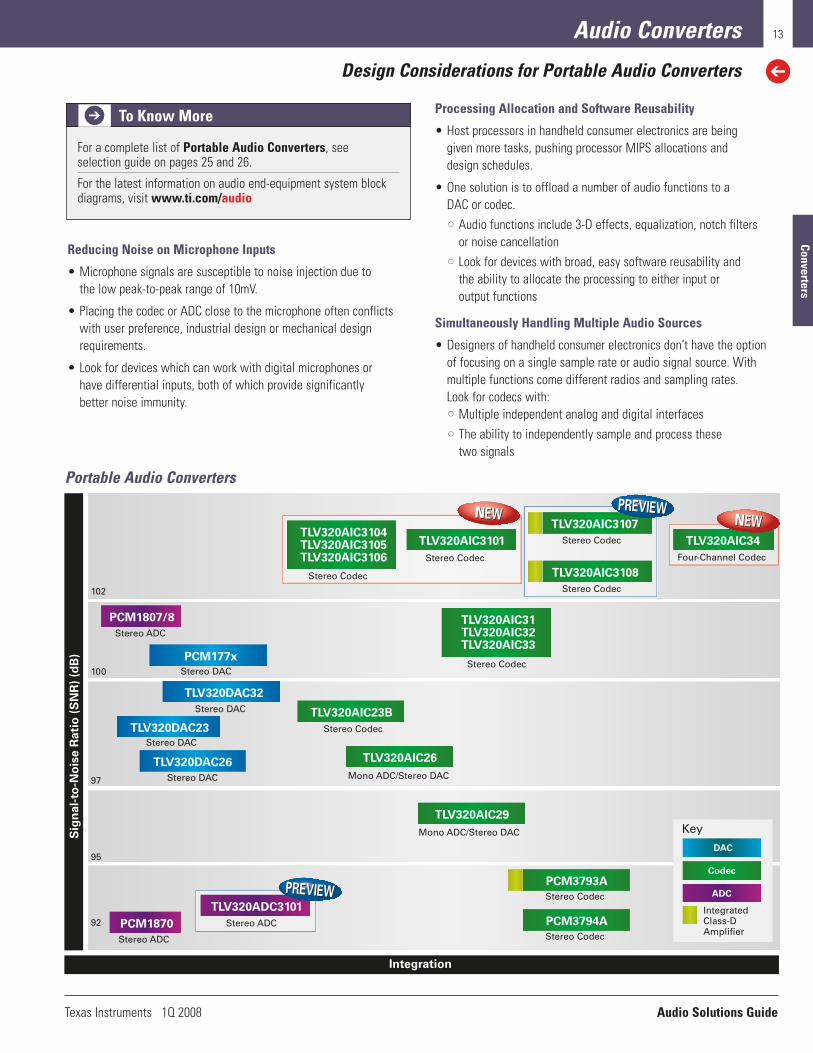
Portable Audio Converters
Reducing Noise on Microphone Inputs
• Microphone signals are susceptible to noise injection due to the low peak-to-peak range of 10mV.
• Placing the codec or ADC close to the microphone often conflictswith user preference, industrial design or mechanical designrequirements.
• Look for devices which can work with digital microphones or have differential inputs, both of which provide significantly better noise immunity.
Processing Allocation and Software Reusability
• Host processors in handheld consumer electronics are being given more tasks, pushing processor MIPS allocations and design schedules.
• One solution is to offload a number of audio functions to a DAC or codec.•• Audio functions include 3-D effects, equalization, notch filters
or noise cancellation•• Look for devices with broad, easy software reusability and
the ability to allocate the processing to either input or output functions
Simultaneously Handling Multiple Audio Sources
• Designers of handheld consumer electronics don’t have the option of focusing on a single sample rate or audio signal source. Withmultiple functions come different radios and sampling rates. Look for codecs with:•• Multiple independent analog and digital interfaces•• The ability to independently sample and process these
two signals
For a complete list of Portable Audio Converters, seeselection guide on pages 25 and 26.
For the latest information on audio end-equipment system block diagrams, visit www.ti.com/audio
To Know More
Converters
Audio Solutions Guide Texas Instruments 1Q 2008
Audio Converters
Design Considerations for Home and Professional Audio Converters
14
SN
R (
dB
)
Integration
120
115
110
105
100
Key
DAC
Codec
ADC
PCM422x
PCM180x
PCM4201
PCM30xx
PCM4202/4 PCM4104
PCM1791/3
PCM1792/4PCM1796/8
PCM16xx
PCM175xPCM174xPCM178x
Stereo ADCs
Stereo ADC/Four-Channel ADC
Stereo DACs
Four-Channel DAC
Stereo DACs
Multichannel DACs
Stereo DACs Stereo CodecsStereo ADCs
Four-Channel Mono ADC PCM31686 x ADC8 x DAC
Multichannel Codec
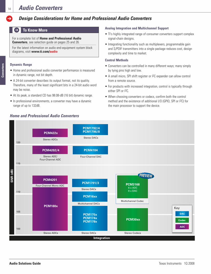
Home and Professional Audio Converters
Dynamic Range
• Home and professional audio converter performance is measured in dynamic range, not bit depth.
• A 24-bit converter describes its output format, not its quality.Therefore, many of the least significant bits in a 24-bit audio wordmay be noise.
• At its peak, a standard CD has 98.08-dB (16 bit) dynamic range.
• In professional environments, a converter may have a dynamicrange of up to 132dB.
Analog Integration and Multichannel Support
• TI's highly integrated range of consumer converters support complexsignal-chain designs.
• Integrating functionality such as multiplexers, programmable gainand S/PDIF transmitters into a single package reduces cost, designcomplexity and time to market.
Control Methods
• Converters can be controlled in many different ways; many simplyby tying pins high and low.
• A small micro, SPI shift register or I2C expander can allow controlfrom a remote source.
• For products with increased integration, control is typically througheither SPI or I2C.
• When choosing converters or codecs, confirm both the controlmethod and the existence of additional I/O (GPIO, SPI or I2C) for the main processor to support the device.
For a complete list of Home and Professional AudioConverters, see selection guide on pages 25 and 26.
For the latest information on audio end-equipment system block diagrams, visit www.ti.com/audio
To Know More
Conv
erte
rs

Texas Instruments 1Q 2008 Audio Solutions Guide
Audio Converters
Design Considerations for Audio Converters with Integrated Touch-Screen Controller
15
• 97-dB Stereo playback• Low-power, 11-mW playback• Programmable audio effects
TSC2102
SN
R (
dB
)
Integration
Touch-Screen Controllers with:
DAC
Codec
• 98-dB Dynamic range• 4-Wire touch-screen interface• I2S Interface
Stereo Codec
Stereo DAC
• 95-dB Dynamic range • 4-Wire touch-screen interface • Programmable audio effects• Stereo, capless headphone amp• Battery-connected speaker amp
TSC2111
Mono ADC/Stereo DAC
TSC2302
• 98-dB Dynamic range• 4-Wire touch-screen interface• I2S Interface
Mono ADC/Stereo DAC
TSC2300
• 98-dB Dynamic range• 4-Wire touch-screen interface• 4x4-Keypad interface• I2S Interface
Stereo Codec
TSC2301
95
97
98
Key
Audio Converters with Integrated Touch-Screen Controller
Using Touch-Screen Controllers (TSCs) to OffloadHost Processing
• TSCs detect contact and then require the host to handle as many as 40 to 50 register read/write cycles.
• These requirements create additional interrupts and processingcycles, which reduces processing efficiency.
• To reduce this load on the host, look for “smart” TSCs with the ability to generate coordinates with minimal interaction from the host.
Other Methods for Using TSCs to Offload Host Processing
• Host processors in handheld consumer electronics are being given more tasks, pushing processor MIPS allocations and design schedules.
• One solution is to offload a number of audio functions to the DAC or codec functions of a TSC. •• Audio functions include 3-D effects, equalization, notch filters
or noise cancellation•• Look for devices with integrated audio, software reusability
and the ability to allocate the processing to either input or output functions
Supporting Varying Mechanical System Designs
• The preferred solution with a single integrated TSC + audio device ora discrete TSC and audio codec may depend on whether a handheld device is built on:•• A single-board platform, such as a candy bar•• A PDA form factor•• An in-dual board platform like a flip phone
• TI offers a wide selection of stand-alone TSCs and audio codecs aswell as integrated TSC + audio devices for all types of system designs.
For a complete list of Audio Converters with IntegratedTouch-Screen Controller, see selection guide on page 27.
For the latest information on audio end-equipment system block diagrams, visit www.ti.com/audio
To Know More
Converters

Audio Solutions Guide Texas Instruments 1Q 2008
16 Interface and Sample Rate Converters
Design Considerations for S/PDIF Interface and Sample Rate Converters
Sample Rate Converters (SRCs)
• SRCs create sample rate and phase-independent interfaces between fixed-rate digital processors and the outside world.
• SRCs can serve as “jitter cleaners,” lowering the amount of jitter on incoming data streams.
• SRCs allow similar phase-independent sample rates to be broughtinto systems without the need for time alignment/word clock distribution.
Jitter Sensitivity
• Jitter can be a major problem in a digital audio system.
• Jitter is introduced when digital audio clocks are generated orregenerated from a different clock source and by using interconnectsthat have significant parasitic impedance (capacitance, inductanceetc.).
• Jitter in digital audio systems moves the sampling instant back and forth in time, adding noticeable distortion in high frequencies.
• For the smallest adverse impact on the audio content, choose S/PDIF receivers with low jitter.
System Partitioning
• System partitioning options include discrete transmitters, receiversand stand-alone SRCs, as well as combinations of transceivers and SRCs.
• Flexible functionality allows end products to be either:•• A clock master (and SRC from the outside to its internal
process clock)•• A slave to an external clock (and SRC the output to the new
clock rate)
S/PDIF Interface Products and Sample Rate Converters
Pe
rfo
rma
nce
• 24 bit, stereo, 212-kHz Fs• 144-dB dynamic range• –140-dB THD+N• 28-pin SSOP
Integration
SRC4192/3
• 24 bit, stereo, 212-kHz Fs• 128-dB dynamic range• –125-dB THD+N• 28-pin SSOP
SRC4190
• 24 bit, 4 channel, 212-kHz Fs• 144-dB dynamic range• –140-dB THD+N• 64-pin TQFP
SRC4194
• 2-channel combo SRC and DIX• 128-dB dynamic range• –125-dB THD+N• 48-pin TQFP
SRC4382
DIT4192 DIR9001
• Pro S/PDIF/AES3 transceiver• Up to 24 bit, stereo, 216kHz• 48-pin TQFP
DIX4192
• Pro S/PDIF/AES3 transmitter• Up to 24 bit, stereo, 96kHz and 192kHz• 28-pin TSSOP
• S/PDIF/AES3 receiver• DIR1703 replacement• Up to 24 bit, stereo, 96kHz• Low 50-pS jitter
DIT4096
• 24 bit, 4 channel, 212-kHz Fs• 128-dB dynamic range• –125-dB THD+N• 64-pin TQFP
SRC4184
Key
SRC
Combo SRC
S/PDIF, AES/EBU
DIT - S/PDIF and AES/EBU TransmitterDIR - S/PDIF and AES/EBU ReceiverDIX - S/PDIF and AES/EBU Transceiver
SRC - Sample Rate Converter
SRC4392
• 2-channel combo SRC and DIX• 144-dB dynamic range• –140-dB THD+N• 48-pin TQFP
For a complete list of S/PDIF Interface and Sample RateConverters, see selection guide on page 28.
For the latest information on audio end-equipment system block diagrams, visit www.ti.com/audio
To Know More
Inte
rfac
e

Texas Instruments 1Q 2008 Audio Solutions Guide
USB Audio
Design Considerations for Audio Controllers and Converters with USB Interface
17
Pe
rfo
rma
nce
an
d I
nte
gra
tio
n
Generation Timeline
Key
USB Audio Controller
• General purpose• Multichannel
TUSB3200
• Self powered
PCM2702
• Self/bus powered• W/SPDIF
• Self/bus powered
PCM2704
• Stereo only• Cost optimized
• Programmable• Stereo and multichannel• Interface to DSPs, codecs, DACs and ADCs
• Single-chip solution• Easy implementation• 92-dB dynamic range
• Single-chip solution• Easy implementation• 98-dB dynamic range
TAS1020B
PCM290xUSB Codec
USB DAC
USB Audio Codec
Streaming Controller
Streaming Controller
USB Audio DAC
USB Audio DAC
• Mono record, stereo playback• Integrated mic preamp• HID interface
PCM2912
USB Codec
Audio Controllers and Converters with USB Interface
Programmable vs. USB Codecs
• For designers with little USB experience, one of the biggest challenges is deciding between a plug-and-play device and one that requires coding.
• TI codecs (PCM2xxx) deliver an extremely simple plug-and-playexperience by being completely USB-class compliant.
• For the highest flexibility and performance defined by an externalconverter, the TAS1020B and TUSB3200A offer completely programmable solutions based on an 8052, 8-bit processor core.
I/O Considerations (S/PDIF, I2S, HID)
• Beyond analog audio in and out, many USB audio products now offer:•• S/PDIF I/O•• Raw PCM data (in I2S form)•• Human interface device (HID) functionality
• HID functionality allows control of PC/Mac applications: •• Mute, volume up/down, play, stop, rewind, fast-forward, etc.
For a complete list of Audio Controllers and Converters withUSB Interface, see selection guide on page 28.
For the latest information on audio end-equipment system block diagrams, visit www.ti.com/audio
To Know More
USB

Audio Solutions Guide Texas Instruments 1Q 2008
18 Processors
Design Considerations for Digital Audio Processors and SoCs
• 1 stereo single-ended ADC• 3 stereo single-ended DACs• 10/3 stereo analog input/ output channels• 135-MHz, 48-bit fully programmable DSP• Graphical programming tool
TAS3208
• 2 stereo differential ADCs• 2 stereo differential DACs• 3/2 stereo analog input/ output channels• 135-MHz, 48-bit fully programmable DSP• Graphical programming tool
TAS3204
• 1 stereo single-ended ADC• 3 stereo differential PWMs• 10/3 stereo analog input/ output channels• 135-MHz, 48-bit fully programmable DSP• Graphical programming tool
TAS3308
• 1 stereo differential ADC• 1 stereo differential DAC• 2/1 stereo analog input/ output channels• 135-MHz, 48-bit fully programmable DSP• Graphical programming tool
TAS3202
• 8 channels • 135-MHz, 48-bit fully programmable DSP• Graphical design tool
• 4/3 input/output channels • 3-D effects, volume, treble/bass, DRC, EQ control • Fully configurable
TAS3103A
Key
Audio SoC
Stand-Alone DSP
TAS3108
Digital Audio Processors
Input Considerations
Audio SoC inputs can be digital or analog.
• Digital inputs in the I2S form are suitable if the audio source is digital in nature, such as an MP3 decoder or DSP.
• Analog inputs can be either single ended or differential.
• Single-ended circuits are simpler and require fewer components.
• Differential circuits offer better noise performance.
• Differential inputs are robust against TDMA noise generated by mobile phones.
Audio Processing Considerations
The digital core of an audio SoC can be based on two types of architectures, ROM or RAM.
• ROM-based cores:•• Are not fully programmable•• Feature a fixed-process flow that can be configured
•Example: Each audio channel might have a bank of seven fixed-frequency bi-quad filters in which only the gains can be altered by a user
• RAM-based cores:•• Are fully programmable
•Example: A user can implement any desired number of bi-quad filters on a channel and specify gain, bandwidth, and center frequency
Output Considerations
Audio SoC outputs can be digital, analog or PWM.
• Digital outputs:•• Are in an I2S or S/PDIF form
•I2S is useful if the output signal is being sent to another IC•S/PDIF is generally used for an output that is expected to be
routed to an external audio system
• Analog outputs:•• Can be either single ended or differential•• Reference input consideration section for benefits of each type
of output
• PWM outputs:•• Can be routed directly to an H-bridge PWM power stage, such
as TI’s TAS53xx family•• Are beneficial because the audio stream is maintained as digital
for as long as possible
For a complete list of Digital Audio Processors and SoCs, seeselection guide on page 29.
For the latest information on audio end-equipment system block diagrams, visit www.ti.com/audio
To Know More
Proc
esso
rs

Texas Instruments 1Q 2008 Audio Solutions Guide
Processors
Design Considerations for PWM Processors
19
• 6 channel• Volume, channel mapping• Bass management• 107-dB dynamic range
TAS5086
• 8 channel• 48-bit audio processing• Volume, channel mapping• PSU volume control• 102-dB dynamic range
TAS5028
• 8 channel• 48-bit audio processing• Volume, EQ, treble/bass, loudness• PSU volume control• 102-dB dynamic range
TAS5508B
• 4 channel• 48-bit audio processing• Volume, EQ, treble/bass, loudness• PSU volume control• 102-dB dynamic range
TAS5504A
• 24 bit, stereo• 94-/96-/102-dB dynamic range• 32 to 192kHz
TAS5001/10/12
TAS5518
• 8 channel• 48-bit audio processing• Volume, EQ, treble/bass, loudness• PSU volume control• 110-dB dynamic range
Key
Pin/SW Compatible
Multichannel
Stereo
PurePath™ PWM Processors
Digital Amplifier Chipset
• The digital audio PWM processor is the first chip in a two-chip digital amplifier chipset.
• It accepts PCM data from a DSP, ADC or interface (S/PDIF) and converts the data into PWM format.
• The PWM data is passed to the power stage that drives the speaker.
• Some PWM processors include a digital audio processor to handlepost-processing functions such as: •• Volume control•• Treble/bass control•• EQ•• Bass management•• Compression/limiting•• Loudness
• Channel counts vary from stereo versions to multichannel, ideal forthe 5.1, 6.1 and 7.1 markets.
• Software configurability and pin-for-pin compatibility allow a singleboard to be used for many design platforms.
For a complete list of PWM Processors, see selection guide onpage 29.
For the latest information on audio end-equipment system block diagrams, visit www.ti.com/audio
To Know More
Processors

Audio Solutions Guide Texas Instruments 1Q 2008
Processors
Design Considerations for Floating-Point Digital Signal Processors
20
Pe
rfo
rma
nce
Time
C31/C3260MHz
C3180MHz
C6701167MHz C6711
150MHz C6712100MHz
C6712D150MHz
C6711D200MHz
C6713225MHz
C6711D250MHz
C6713300MHz
C6722250/200MHz
C6720200MHz
C6726250MHz
Future
VC3360/75MHz
F I R S T G E N E R A T I O N S E C O N D G E N E R A T I O N
Software Compatible
Float in
g Poin
t
T H I R D G E N E R A T I O N
Key
Production
Announcement
Future
C6727300/250MHz
TMS320C6000™ Floating-Point DSP Roadmap
TMS320C67x™ processors, the industry’s highest performance floating-point DSPs, offer precision, speed, power savings and dynamic range with performance ranging from 600 to 1800 MFLOPS.These devices are ideal for professional audio products, mixers, audio synthesis, instrument/amplifier modeling, audio conferencing andbroadcast; biometrics, medical, industrial, digital imaging, speechrecognition and voice-over packet.
Key Features
• 100% code-compatible DSPs priced as low as $5.75
• Advanced VLIW architecture
• Up to eight 32-bit instructions executed each cycle
• Eight independent, multi-purpose functional units and up to sixty-four 32-bit registers
• Industry’s most advanced DSP C compiler and assembly optimizermaximize efficiency and performance
C672x DSP
• Lowest price floating-point device on the market
• Sixty-four 32-bit registers
• Large (32-KB) program cache
• Flexible boot options
• dMAX DMA engine tuned for audio performance
C671x DSP
• L1/L2 cache architecture
• Thirty-two 32-bit registers
• EDMA DMA engine
Applications
• Professional audio products, mixers, audio synthesis
• Instrument/amplifier modeling
• Audio conferencing
• Audio broadcast
• Emerging audio applications in biometrics, medical, industrial, digital imaging, speech recognition and voice-over packet
For a complete list of Floating-Point Digital SignalProcessors, see selection guide on page 29.
For the latest information on audio end-equipment system block diagrams, visit www.ti.com/audio
To Know More
Proc
esso
rs

Texas Instruments 1Q 2008 Audio Solutions Guide
Analog Switches
Design Considerations for Analog Multiplexers and Switches
21
Sp
ecif
ied
Vo
ltag
e R
an
ge (
V+
)
ON-State Resistance Range (ron)
5
4
3
2
1
0.25 to 3Ω 8 to 15Ω
• Low voltage• Low ron
TS3A4xxxTS3A24xxx
Series
• Low voltage• Lower Con• Higher bandwidth
TS3A5xxxSeries
• Low ron• Wide operating range
TS5A31xxTS5A231xxTS5A46xx
Series
• Low ron• Wide operating range• High ESD• Control input voltage range
TS5A6xxxTS5A26xxx
Series
• Lower Con• Higher bandwidth
TS5A1xxxTS5A2xxxTS5A45xx
Series
Analog Switches
V+ and the Max Analog Signal Amplitude
• V+ determines the analog signal amplitude that can be passedwithout clipping for noncharge-pump switches.
• The gate(s) of the pass transistors must be biased relative to theminimum and maximum values of the expected input voltage range.
• Some switches allow for biasing from two supplies, making it easyto pass both positive and negative signals.
• Switches with integrated charge pumps can elevate the gate voltage above V+ (at the expense of larger I+) and thus pass signals of a magnitude greater than V+.
VIH/VIL Compatibility
• The signal switch is controlled by the output of a digital source inmost applications.
• The control signal levels, VIH and VIL, must be compatible with thedigital source to ensure proper operation of the switch.
On-State Resistance (ron) Tradeoffs
• ron contributes to signal loss and degradation.
• Non-charge-pump switches achieve low ron with large pass transistors.•• Leads to larger die sizes and increased channel capacitance (CI/O)•• Limits the frequency response of the switch
• Switches using charge-pump technology can achieve low ron andCI/O but require significantly higher I+.
On-State Resistance Flatness [ron(flat)]
• On-state resistance flatness specifies the minimum and maximumvalue of ron over the specified range of conditions.
• Conditions may include changes in temperature or supply voltage.
For a complete list of Analog Multiplexers and Switches, seeselection guide on page 32.
For the latest information on audio end-equipment system block diagrams, visit www.ti.com/audio
To Know More
Switches

Audio Solutions Guide Texas Instruments 1Q 2008
22 Selection Guides
Audio Amplifiers (Class-D)
Sele
ctio
n G
uide
s
PWM-Input Class-D Power Stages (PurePathTM) Device Description Power (W) Channel(s) Half Power THD+N at 1kHz (%) Package(s) Price1
TAS5261 Mono, High Power 315 (4Ω) 1 0.05 SSOP-36 5.25TAS5162 Stereo, High Power 200 (6Ω) 2 0.05 SSOP-36, HTSSOP-44 4.95TAS5152 High Power, Pin Compatible with TAS5142 125 (4Ω) 2 0.1 SSOP-36 3.40TAS5121 Mono, High Power 100 (4Ω) 1 0.05 SSOP-36 3.00TAS5142 High Power, Pin Compatible with TAS5152 100 (4Ω) 2 0.1 SSOP-36, HTSSOP-44 3.10TAS5182 Controller Only, For Use with External FETs 100 (6Ω) 2 0.15 HTSSOP-56 5.26TAS5111A Mono, Medium Power 70 (4Ω) 1 0.025 HTSSOP-32 2.40TAS5112A Stereo, Medium Power 50 (6Ω) 2 0.025 HTSSOP-56 3.75TAS5176 6-Channel, Medium Power 100 (Total) 6 < 0.05 HTSSOP-44 4.30TAS5186A Highest Integration Power 30/60 (6/3Ω) 6 0.07 HTSSOP-44 5.10TAS5122 Stereo, Low Power 30 (6Ω) 2 0.05 HTSSOP-56 3.00TAS5132 Stereo, Low Power 25 (6Ω) 2 0.03 HTSSOP-44 1.95TAS5342 100-W, Stereo, Digital Power 100 (4Ω) 2 <0.1 HTSSOP-44 2.95TAS5342L 100-W, Stereo, Digital Power 100 (4Ω) 2 <0.1 HTSSOP-44 2.75TAS5352 125-W, Stereo, Digital Power 125 (4Ω) 2 <0.1 HTSSOP-44 3.10TAS5601 Multichannel, Low Power 40 (Total) 4 < 0.1 HTSSOP-56 TBD
Analog-Input Class-D Speaker AmplifiersMin Load Power Half Power
Output Impedance Supply (V) THD+N PSRRDevice Description Power (W) (Ω) (min) (max) at 1kHz (%) (dB) Package(s) Price1
TPA3122D2 Stereo, High Output Power, Internal Gain, Single-Ended Outputs 15 4 10 30 < 0.15 55 @ 2kHz PDIP-20 2.60TPA3121D2 Stereo, Medium Output Power, Internal Gain, Single-Ended Outputs 10 4 10 26 < 0.2 55 @ 2kHz TSSOP-24 TBDTPA3106D1 Mono, High Output Power, Internal Gain 40 4 10 26 0.2 70 HLQFP-32 3.55TPA3009D2 Stereo, Medium Power Output with Volume Control 6 8 8.5 14 0.045 80 HTQFP-48 TBDTPA3123D2 Stereo, High Output Power, Internal Gain, Single-Ended Outputs 25 4 10 30 0.08 55 @ 2kHz HTSSOP-24 3.20TPA3100D2 Stereo, High Output Power, Mute, Internal Gain, Auto Re-Start, Wide Supply Voltage 20 4 10 26 0.1 80 HTQFP-48, QFN-48 3.50TPA3001D1 Mono, High Output Power, Internal Gain, Differential Input 20 4 8 18 0.06 73 HTSSOP-24 2.50TPA3107D2 Stereo, Class-D 15 6 10 26 0.08 70 HTQFP-64 3.35TPA3004D2 Stereo, Volume Control 12 4 8.5 18 0.1 80 HTQFP-48 3.25TPA3101D2 Stereo, Mute, Internal Gain, Auto Re-Start, Wide Supply Voltage 10 4 10 26 0.1 80 HTQFP-48, QFN-48 3.10TPA3008D2 Stereo, Class-D 10 8 8.5 18 0.1 80 HTQFP-48 3.10TPA3002D2 Stereo, Medium Power Class-D with Volume Control 9 8 8.5 14 0.06 80 HTQFP-48 3.30TPA3007D1 Mono, Medium Power, Internal Gain 6.5 8 8 18 0.2 73 TSSOP-24 1.95TPA3005D2 Stereo, Medium Power 6 8 8 18 0.1 80 HTQFP-48 2.95TPA3003D2 Stereo, Volume Control, Lower Max Voltage 3 8 8.5 14 0.2 80 TQFP-48 3.00TPA2008D2 Stereo, Medium Power, Volume Control, Ideal for Docking Stations 3 3 4.5 5.5 0.05 70 TSSOP 1.80TPA2000D1 Mono, Internal Gain, Cost Effective Solution 2.7 4 2.7 5.5 0.08 77 TSSOP-16, BGA-48 1.05TPA2010D1 Mono, Fully Differential, 1.45mm x 1.45mm WCSP Package, High Power 2.5 4 2.5 5.5 0.2 75 WCSP 0.55TPA2000D2 Stereo, Medium Power, Ideal for Docking Stations 2.5 3 4.5 5.5 0.05 77 TSSOP 1.40TPA2012D2 Smallest Stereo Amp in 2mm x 2mm WCSP Package 2.1 4 2.5 5.5 0.2 75 WCSP, QFN 0.95TPA203xD1 Smallest Solution Size, Mono, Fully Differential, Internal Gain 2V/V, 3V/V, 4V/V 2.1 4 2.5 5.5 0.2 75 WCSP 0.60TPA2000D4 Stereo with Headphone Amp, Medium Power, Ideal for Docking Stations 2.5 4 3.7 5.5 0.1 70 TSSOP 1.65TPA2013D1 Mono, Integrated Boost Converter, High and Constant Power 1.8 8 1.6 5.5 0.2 90 QFN, WCSP 1.45TPA2006D1 Mono, Fully Differential, 1.8-V Compatible Shutdown Voltage 1.45 8 2.5 5.5 0.2 75 QFN 0.49TPA2005D1 Mono, Fully Differential, Most Package Options 1.4 8 2.5 5.5 0.2 75 BGA, QFN, MSOP 0.49TPA2001D2 Stereo, Lower Power, Ideal for Docking Stations 1.25 8 4.5 5.5 0.08 77 TSSOP 1.20
New products are listed in bold red. Preview products are listed in bold blue.
See page 29 for complementary PWM processors for PurePath™ power stages.1Suggested resale price in U.S. dollars in quantities of 1,000.
Digital-Input Class-D Speaker Amplifiers (PurePathTM)Min Load Power Half Power
Max Closed Output Impedance Supply (PVDD) THD+N at Dynamic On ChipDevice Description Channels Loop Power (W) (Ω) (Typ) (min) (max) 1kHz (%) Range (dB) DRC/EQ I2C Price1
TAS5701 Stereo, Hardware Control 2 No 20 (8 Ω) 8 0 21 < 0.1 100 No No TBDTAS5704 Multichannel, Hardware Control, Closed Loop 4 Yes 20 (8 Ω) 4 10 26 < 0.1 100 No No TBDTAS5705 Stereo, Audio Processing, Software Control 2 No 20 (8 Ω) 8 8 21 < 0.1 100 Yes Yes TBDTAS5706 Multichannel, Audio Processing, Closed Loop 4 Yes 20 (8 Ω) 4 10 26 < 0.1 100 Yes Yes 4.35

Texas Instruments 1Q 2008 Audio Solutions Guide
23
Selection Guides
Audio Amplifiers (Class-AB)
Class-AB Speaker AmplifiersMin. Load Power Half Power
Output Impedance Supply (V) THD+N at PSRRDevice Description Power (W) (Ω) (min) (max) 1kHz (%) (dB) Package(s) Price4
TPA6030A4 Stereo with Stereo HP, Wide Supply Voltage, Low Power, Volume Control, Fully Differential 3 16 7 15 0.06 60 HTSSOP-28 1.40TPA6017A2 Stereo, Cost Effective, Internal Gain, Fully Differential 2.6 3 4.5 5.5 0.1 77 HTSSOP-20 0.99TPA6011A4 Stereo with Stereo HP, Volume Control, Fully Differential 2.6 3 4 5.5 0.06 70 HTSSOP-24 1.20TPA6010A4 Stereo with Stereo HP, Volume Control and Bass Boost, Fully Differential 2.6 3 4.5 5.5 0.06 67 HTSSOP-28 2.25TPA1517 Stereo, Mute, Medium Power, Low Cost, DIP Package, Single Ended 6 4 9.5 18 0.15 65 PDIP-20, SO-20 0.85TPA6021A4 Stereo with Stereo HP, Volume Control, Fully Differential 2 4 4 5.5 0.19 70 PDIP-20 1.00TPA6020A2 Stereo, Fully Differential, Low Voltage, Smallest Package 2.8 3 2.5 5.5 0.05 85 QFN-20 1.15TPA6211A1 Mono, Fully Differential, Highest Power 3.1 3 2.5 5.5 0.05 85 MSOP, QFN 0.55TPA6203A1 Mono, Fully Differential, Lower Cost Solution 1.5 8 2.5 5.5 0.06 90 BGA 0.45TPA6204A1 Mono, Fully Differential, High Power 1.7 8 2.5 5.5 0.05 85 QFN 0.49TPA6205A1 Mono, Fully Differential, 1.8-V Compatible Shutdown Voltage 1.5 8 2.5 5.5 0.06 90 MSOP, QFN, BGA 0.45TPA751 Mono, Differential Inputs, Active Low 0.9 8 2.5 5.5 0.15 78 SOIC, MSOP 0.35TPA731 Mono, Differential Inputs, Active High 0.9 8 2.5 5.5 0.15 78 SOIC, MSOP 0.35TPA721 Mono, Single Ended Inputs, Active High 0.9 8 2.5 5.5 0.15 85 SOIC, MSOP 0.35TPA711 Mono, Single Ended Inputs, Active High, Mono Headphone 0.9 8 2.5 5.5 0.15 85 SOIC, MSOP 0.35TPA0233 Mono with Stereo Headphone, Summed Inputs 2.7 4 2.5 5.5 0.06 75 MSOP 1.05TPA0253 Mono with Stereo Headphone, Summed Inputs 1.25 8 2.5 5.5 0.1 75 MSOP 0.50TPA0172 Stereo with Stereo Headphone, Mute Function, I2C Volume Control 2.0 4 4.5 5.5 0.08 75 TSSOP 2.45TPA0212 Stereo with Stereo Headphone, Internal Gain, Low-Cost Computing Solution 2.6 3 4.5 5.5 0.15 77 TSSOP 1.06
Headphone AmplifiersTPA6120A2 Stereo, Hi-Fi, Current Feedback, 80mW into 600Ω from a ±12V Supply at 1.5 32 10 30 0.0005 75 SO-20 1.90
0.00014% THD+NTPA6112A2 Stereo, Differential Inputs, 10µA ISD 0.15 8 2.5 5.5 0.25 83 MSOP-10 0.29TPA6111A2 Low Cost, Stereo Headphone, SOIC Package, 1µA ISD 0.15 8 2.5 5.5 0.25 83 SOIC-8, MSOP-8 0.29TPA6110A2 Stereo Headphone, 10µA ISD 0.15 8 2.5 5.5 0.25 83 MSOP-8 0.29TPA6130A2 DirectPath™, Stereo with I2C Volume Control 0.138 16 2.5 5.5 0.0055 109 QFN, WCSP 1.45TPA4411 DirectPath, Stereo, Internal Gain 0.08 16 1.8 4.5 0.08 80 DSBGA-16, QFN-20 0.70TPA152 Hi-Fi, Stereo, Mute 0.075 32 4.5 5.5 0.007 81 SOIC-8 0.55TPA6102A2 Ultra-Low Voltage, Stereo, Fixed Gain (14dB) 0.05 16 1.6 3.6 0.1 72 SOIC-8, MSOP-8 0.35TPA6101A2 Ultra-Low Voltage, Stereo, Fixed Gain (2dB) 0.05 16 1.6 3.6 0.1 72 SOIC-8, MSOP-8 0.35TPA6100A2 Ultra-Low Voltage, Stereo, External Resistors 0.05 16 1.6 3.6 0.1 72 SOIC-8, MSOP-8 0.35
Preview products are listed in bold blue. Selection Guides
1Power output into a 4-Ω load with 10% THD and 5-V power supply.2Power output into a 8-Ω load with 10% THD and 5-V power supply.3Power output into a 16-Ω load with 10% THD and 5-V power supply.4Suggested resale price in U.S. dollars in quantities of 1,000.
Low-Power Audio Amplifier Sub SystemsSpeaker Headphone Power Half PowerOutput Output Supply (V) THD+N PSRR
Device Description Power (W) Power3 (W) (min) (max) at 1kHz (%) (dB) Package(s) Price4
TPA6040A4 Stereo Class-AB and DirectPath™ Headphones and 4.75-V LDO 2.01 0.2 4.5 5.5 0.1 80 32-pin, 5x5 QFN 1.15TPA6041A4 Stereo Class-AB and DirectPath Headphones and 3.3-V LDO 2.01 0.2 4.5 5.5 0.1 80 32-pin, 5x5 QFN 1.15TPA6043A4 Stereo Class-AB and DirectPath Headphones and 3.3-V LDO 2.01 0.2 4.5 5.5 0.1 80 32-pin, 5x5 QFN 1.15TPA2050D4 Stereo Class-D and DirectPath Headphones (2 Inputs) 1.32 0.138 2.5 5.5 0.1 75 WCSP TBDTPA2052D4 Stereo Class-D and DirectPath Headphones (3 Inputs) 1.32 0.138 2.5 5.5 0.1 75 WCSP TBD

Selection Guides
Audio Amplifiers
24
Microphone PreamplifiersGain Range Noise (EIN), Half Power THD+N Power Supply
Device Description (dB) G = 30dB at 1kHz (%) (V) Package Price3
PGA2500 Digitally Controlled, Fully Differential, High Performance, Low Noise, 0dB, and 10dB to –128dBu 0.0004 ±5 SSOP-28 9.95Wide Dynamic Range, On-Chip DC Servo Loop 65dB in 1dB steps
Slew Rate GBW Half Power THD+N Power SupplyDevice Description (V/µs) (MHz) at 1kHz (%) (V) Package(s) Price3
INA163 Mono, Low Noise, Low Distortion, Current Feedback, Wide Bandwidth, Wide Range of Gain 15 8 0.0003 ±4.5 to ±18 SO-14 2.90INA217 Mono, Low Noise, Low Distortion, Current Feedback, Wide Bandwidth, Wide Range of Gain 15 8 0.004 ±4.5 to ±18 PDIP-8, SOIC-16 2.50
Line DriversPower Supply Half Power THD+N Slew Rate GBW
Device Description (V) at 1kHz (%) (V/µs) (MHz) Package(s) Price3
DRV134 Balanced Output, DIP Pkg., Companion to INA134 and INA137 ±4.5 to ±18 0.0005 12 1.5 SOIC-16, PDIP-8 1.95DRV135 Balanced Output, Small Pkg., Companion to INA134 and INA137 ±4.5 to ±18 0.0005 12 1.5 SOIC-8 1.95Line ReceiversINAy1341 Differential, Fixed Gain, 0dB (G=1) 1V/V ±4 to ±18 0.0005 14 3.1 PDIP-8/14, SOIC-8/14 1.05INAy1371 Differential, ±6dB (G=1/2 or 2) ±4 to ±18 0.0005 14 4 PDIP-8/14, SOIC-8/14 TBD
Signal Conditioning AmplifiersPower Half Power SlewSupply THD+N at Rate GBW
Device Description Channel(s) (V) 1kHz (%) (V/µs) (MHz) Package(s) Price3
FET AmplifiersOPAx827 Ultra-Low THD+N, High Precision 1, 2 ±4 to ±18 0.00004 22 18 MSOP, SOIC 5.75OPAx627 Difet, Low Noise, High Slew Rate 1 ±4.5 to ±18 0.00003 55 16 PDIP-8, SOIC-8 12.25OPAx604 FET Input, Low Distortion, Single Channel, Wide Supply Range, Unity Gain Stable 1, 2 ±4.5 to ±24 0.0003 25 20 PDIP-8, SOIC-8 1.05OPAx134 High Performance, Ultra-Low Distortion, True FET-Input 1, 2, 4 ±2.5 to ±18 0.00008 20 8 PDIP-8, SOIC-8/14 0.95Bipolar AmplifiersOPAx211 Ultra-Low Noise, High Precision 1, 2 ±2.5 to ±18 0.000015 27 45 MSOP, SOIC, SON 3.45OPA1632 High Performance, Fully Differential, High Speed, Wide Supply Range, High Gain Bandwidth 1 5 to 32 0.00003 50 180 MSOP-8, SOIC-8 1.75OPAx228 High Precision, Low Noise: 3nV/√Hz, Improved Settling Time: 5µs 1, 2, 4 ±2.5 to ±18 0.00005 10 33 PDIP-8/14, SOIC-8/14 1.10OPAx353 Single Supply, Rail-to-Rail, Unity Gain Stable 1, 2, 4 2.7 to 5.5 0.0006 22 44 MSOP-8, SOIC-8/16 1.00MC33078 Dual, Bipolar, Dual Supply Operation, Skew Rate of 7V/µs (typ), Input Noise Voltage of 4.5nV/√Hz 2 ±10 to ±36 — 7 16 MSOP-8, PDIP-8, SOIC-8 0.30NE5532A/4A Low Noise, Input Noise Voltage of 3.5nV/√Hz (5532A) and 5nV/√Hz (5532A) 2/1 ±3 to ±20 — 9/13 10 PDIP-8, SO-8, SOIC-8 0.68RC4580 Dual, Lower Noise, High Gain, Wide Bandwidth, Capable of Driving 20V Peak-to-Peak into 400-Ω Loads 2 ±2 to ±18 0.0005 5 12 PDIP-8, SOIC-8, TSSOP-8 0.41RC4560 Dual, High Gain, Wide Bandwidth, Capable of Driving 20V Peak-to-Peak into 400-Ω Loads 2 ±2 to ±18 0.05 5.5 15 PDIP-8, SOIC-8, TSSOP-8 0.41
Volume ControlsPower Voltage
Dynamic Half Power THD+N Crosstalk at Supply SwingDevice Description Range (dB) at 1kHz (%) 1kHz (dBFS) (V) (VPP) Package(s) Price3
PGA2320 ±15V, Improved THD, Pin Compatible with PGA2310, Voltage Swing of 28Vpp 120 0.0003 –126 ±15 27 SOL-16 7.95PGA2310 ±15V, DIP Package, Pin Compatible with PGA2311, Voltage Swing of 27Vpp 120 0.0004 –126 ±15 27 SOL-16, DIP-16 9.95PGA2311U2 2-Channel, ±5V, Low Inter-Channel Crosstalk, Voltage Swing of 7.5Vpp 120 0.0002 –130 ±5 7.5 SOL-16, DIP-16 3.95PGA4311U2 4-Channel, ±5V, Low Inter-Channel Crosstalk, Voltage Swing of 7.5Vpp 120 0.0002 –130 ±5 7.5 SOP-28 5.95
1y denotes dual and/or quad versions available.2U indicates U-Grade devices.3Suggested resale price in U.S. dollars in quantities of 1,000.
Preview products are listed in bold blue.New products are listed in bold red.
Audio Solutions Guide Texas Instruments 1Q 2008
Sele
ctio
n G
uide
s
2VRMS Line DriversGain Power Supply Slew Rate Drive
Device Description (V/V) (V) (V/µs) (typ) Capability Price3
DRV600 Fixed-Gain, Single-Supply, Ground-Biased Output 2VRMS Line Driver 1.5 ±1.8 to ±4.5 2.2 2VRMS 600-Ω Load 0.75DRV601 Variable-Gain, Single-Supply, Ground-Biased Output 2VRMS Line Driver Variable ±1.8 to ±4.5 2.2 2VRMS 600-Ω Load 0.75

Audio ADCsNo. of
Dynamic Inputs/ Sampling Audio PowerPortable Range No. of Rate Data Supply
Device Description Focus (dB) Outputs (kHz) (max) Format (V) Package(s) Price1
PCM4222 2-Channel, High-Performance ∆Σ ADC — 124 2/0 216 6-Bit Modulator, +3.3 and +4 TQFP-48 14.95DSD, Normal,
I2S, TDMPCM4220 2-Channel, High-Performance ∆Σ ADC — 123 2/0 216 Normal, I2S, TDM +3.3 and +4 TQFP-48 9.95PCM4204 4-Channel, High-Performance ∆Σ ADC, PCM or DSD, High Pass Filter — 118 4/0 216 Normal, I2S, DSD, +3.3 and +5 TQFP-64 7.95
TDMPCM4202 Stereo, High-Performance ∆Σ ADC, PCM or DSD, High Pass Filter — 118 2/0 216 Normal, I2S, DSD +3.3 and +5 SSOP-28 4.95PCM4201 Mono, High-Performance ∆Σ ADC, PCM or DSD, High Pass Filter, — 112 1/0 108 Normal, DSP +3.3 and +5 TSSOP-16 2.50
Wide Digital Supply Range, Low Power DissipationPCM1804 Stereo ADC, Fully Differential, High Pass Filter — 112 2/0 192 Normal, I2S, DSD +3.3 and +5 SSOP-28 3.95PCM1802 Stereo ADC, SE Input — 105 2/0 96 Normal, I2S +3.3 and +5 SSOP-20 3.35PCM1803A Stereo ADC, SE Input, High Pass Filter — 103 2/0 96 Normal, I2S +3.5 and +5 SSOP-20 1.10PCM1850/1 Stereo ADC w/2 x 6 Input MUX and PGA, SPI (1850) and I2C (1851) Control — 101 2/0 96 Normal, I2S +3.3 and +5 TQFP-32 4.80PCM1807/8 Stereo ADC, SE Input, Mute w/Fade, SPI Control, S/W (1807) H/W — 101 2/0 96 I2S, L +3.5 and +5 TSSOP-14 1.00
(1808) ControlledPCM1870 Stereo ADC, SE Input, Digital Filter, Very Low Power Consumption 90 2/0 50 Normal, I2S, DSP +2.4 and +3.6 QFN-24 1.80
Audio DACsPCM1792A Stereo, Optional DSD Format, External Filter and DSP Interface, SPI/I2C, — 132 0/2 192 Standard, +3.3 and +5 SSOP-28 9.95
Differential Current Output: 7.8 mA p-p I2S, LPCM1796/8 Stereo Advanced Segment, 123dB Dynamic Range, TDMCA Serial — 123 0/2 192 Standard, +3.5 and +5 SSOP-28 2.95
Interface (1798) I2S, LPCM4104 4-Channel, High Performance, Sampling Rate up to 216kHz, H/W — 118 0/4 216 Normal, I2S, +3.3 and +5 TQFP-48 4.95
or S/W Controlled TDMPCM1738/30 Stereo Advanced Segment DAC, Soft Mute (1730), 2 Optional — 117 0/2 192 Normal, I2S, +3.3 and +5 SSOP-28 5.25/
Operation Modes (1738): External Filter and DSD Decoder for DSD 5.00SACD Playback and Digital Attenuation
PCM1791A Stereo Advanced Segment DAC, Optional DSD Format, External Filter — 113 0/2 192 Normal, I2S, +3.3 and +5 SSOP-28 2.10and DSP Interface, SPI/I2C Differential Current Output: 3.2 mAp-p TDMCA
PCM1793 Stereo Advanced Segment DAC, Balanced Voltage Outputs, Improved — 113 0/2 192 Normal, I2S, +3.3 and +5 SSOP-28 2.10Clock Jitter Left Justified
DSD1608 8-Channel, Enhanced Multiformat ∆Σ DAC, Supports DSD with TDMCA — 108 0/8 192 Normal, I2S, +3.3 and +5 TQFP-52 5.96DSD
PCM1780/81/82 Stereo with Volume Control, Software (1780/82) and Hardware (1781), — 106 0/2 192 Normal, I2S +5 SSOP-16 1.10Open-Drain Output Zero Flag (1782), Improved Jitter Performance
PCM1753/54/55 Stereo with Volume Control, Software (1753/55) and Hardware (1754), — 106 0/2 192 Normal, I2S +5 SSOP-16 1.03Open-Drain Output Zero Flag (1755)
PCM1608 8-Channel, Highly Integrated DAC, Higher SNR — 105 0/8 192 Normal, I2S +3.3 and +5 LQFP-48 4.29PCM1606 6-Channel, Low Cost CMOS, Multilevel — 103 0/6 192 Normal, I2S +5 SSOP-20 2.00PCM1680 8-Channel, Low Cost DAC, Improved Jitter Performance, Pin Compatible — 103 0/8 192 Normal, I2S +5 SSOP-24 1.50
with PCM1780TLV320DAC23 I2C and SPI Control with Headphone Amp, Pdiss = 23mW 100 0/2 96 Normal, I2S, DSP +1.5 to +3.3 VFBGA-80 2.00PCM1770/1 Stereo with Integrated Headphone Driver, Software (1770) and Hardware 98 0/2 48 Normal, I2S +1.6 to +3.6 TSSOP-28, 1.25
(1771) Controlled QFN-28,TSSOP-16,
QFN-20PCM1772/3 Stereo with Integrated Line Out, Software (1772) and Hardware (1773) 98 0/2 48 Normal, I2S +1.6 to +3.6 TSSOP-16, 1.25
Controlled QFN-20TLV320DAC26 Integrated PLL, SPI Control, Speaker/Headphone Amp, Pdiss = 11mW 97 0/2 53 Normal, I2S, DSP +2.7 to +3.6 QFN-32 2.95TLV320DAC32 Low-Power Stereo DAC with PLL and Stereo HP/Speaker Amplifiers 95 0/2 96 Normal, I2S, +2.7 to +3.6 QFN-32 2.75
DSP, TDM
Texas Instruments 1Q 2008 Audio Solutions Guide
Selection Guides
Audio Converters
25
1Suggested resale price in U.S. dollars in quantities of 1,000.
Selection Guides

Audio Solutions Guide Texas Instruments 1Q 2008
Selection Guides
Audio Converters
26
Audio CodecsPortable Dynamic Sampling Rate Audio Data Power
Device Description Focus Range (dB) (kHz) (max) Format Supply (V) Package(s) Price1
PCM3168 High-Performance, 6in/8out-Audio Codec — 112 96 Normal, I2S, 3.3 to 5 HTQFP-64 TBDDSP, TDM
TLV320AIC34 Low-Power Quad Stereo (4-Channel) Codec, 12 Inputs (Mic/Line), 102 96 Normal, +2.7 to 3.6 BGA-87 5.9514 Outputs (Line, Headphone/Speaker), 2 PLLs and Audio Serial I2S, DSP, TDMBuses Allow Fully Asynchronous Simultaneous Codec Operation
TLV320AIC3101 Low-Power Stereo Codec, Integrated PLL, 6 Inputs (Mic/Line), 102 96 Normal, +2.7 to 3.6 QFN-32 3.556 Outputs (Line, Headphone/Speaker), Notch Filtering, Low-Power I2S, DSP, TDMAnalog Bypass
TLV320AIC3104 Low-Power Stereo Codec, Integrated PLL, 6 Inputs (MicLine), 102 96 Normal, +2.7 to 3.6 QFN-32 3.256 Outputs (Line, Headphone), Notch Filtering, Low-Power I2S, DSP, TDMAnalog Bypass
TLV320AIC3105 Low-Power Stereo Codec, Integrated PLL, 6 SE Inputs (Mic/Line), 102 96 Normal, +2.7 to 3.6 QFN-32 3.256 Outputs (Line, Headphone), Notch Filtering, Low-Power I2S, DSP, TDMAnalog Bypass
TLV320AIC3106 Low-Power Stereo Codec, Integrated PLL, 10 Inputs (Mic/Line), 102 96 Normal, +2.7 to 3.6 QFN-32, 3.857 Outputs (Line, Headphone), Notch Filtering, Low Power I2S, DSP, TDM BGA-80Analog Bypass
TLV320AIC3107 Low-Power Stereo Codec, Integrated PLL, 10 Inputs (Mic/Line), 102 96 Normal, +2.7 to 3.6 QFN TBD7 Outputs (Line, Headphone, Mono Integrated Class-D Amp) I2S, DSP, TDM
TLV320AIC3108 Low-Power Stereo Codec, Integrated PLL, 10 Inputs (Mic/Line), 102 96 Normal, +2.7 to 3.6 QFN TBD7 Outputs (Line, Headphone, Stereo Integrated Class-D Amp) I2S, DSP, TDM
TLV320AIC33 Low-Power Stereo Codec, Integrated PLL, 6 Inputs, 102 96 Normal, +2.7 to 3.6 QFN-48, 3.953 Line Out and Speaker/HP Outputs I2S, DSP, TDM BGA-80
TLV320AIC31/32 Low-Power Stereo Codec, Integrated PLL, 6 Inputs 100 96 Normal, +2.7 to 3.6 QFN-32 3.45(AIC32-6 Single-Ended, AIC31-2 Differential and 2 Single Ended) I2S, DSP, TDM2 Line Out and Speaker/HP Outputs
TLV320AIC23B Low-Power, Lower Cost, Stereo Codec with Headphone Amps 100 96 I2S, L, R +2.7 to 3.3 VFBGA-80, 3.00TSSOP-28, QFN-28
TLV320AIC28/29 Low-Power, Stereo DAC, Mono ADC, Integrated PLL, Speaker/HP 95 53 Normal, +2.7 to 3.6 QFN-48 3.95/3.45Amp, Additional Inputs and Outputs (AIC29 – Differential) I2S, DSP
TLV320AIC26 Low-Power, Lower Cost, Stereo DAC, Mono ADC, 97 53 Normal, +2.7 to 3.6 QFN-32 3.25Integrated PLL, Speaker/HP Amp I2S, DSP
PCM3000 Stereo Audio Codec 18-Bits, 98 48 Normal, I2S, +4.5 to 5.5 SSOP-28 3.45Serial Interface, Software Controlled DSP
PCM3001 Stereo Audio Codec 18-Bits, 98 48 Normal, I2S, +4.5 to 5.5 SSOP-28 3.45Serial Interface, Hardware Controlled DSP
PCM3006 Low-Power, 3V Supply, Stereo Codec, Hardware Controlled 93 48 Normal +2.7 to 3.6 SSOP-24 3.45PCM3008 Low-Power, 2.4V Single Supply, Stereo Codec, 88 48 Normal, I2S +2.1 to 3.6 TSSOP-16 3.10
Low-Cost, Hardware ControlledPCM3793A Ultra Low-Power Stereo Codec, 6 Inputs (Mic/Line), 3 Outputs 93 48 Normal, I2S, +2.4 to 3.6 QFN-32 4.50
(Line/HP/Class-D Speaker) DSPPCM3794A Ultra Low-Power Stereo Codec, 6 Inputs (Mic/Line), 93 48 Normal, I2S, +2.4 to 3.6 QFN-32 4.25
5 Outputs (Line/HP) DSP
Preview products are listed in bold blue.New products are listed in bold red.
1Suggested resale price in U.S. dollars in quantities of 1,000.
Sele
ctio
n G
uide
s
Texas Instruments 1Q 2008 Audio Solutions Guide
Selection Guides
Audio Converters and Controllers
27
1Suggested resale price in U.S. dollars in quantities of 1,000.
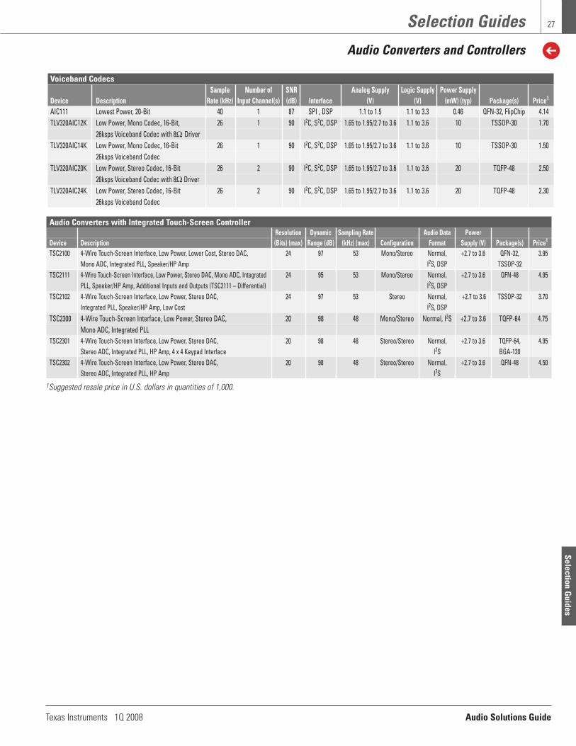
Voiceband CodecsSample Number of SNR Analog Supply Logic Supply Power Supply
Device Description Rate (kHz) Input Channel(s) (dB) Interface (V) (V) (mW) (typ) Package(s) Price1
AIC111 Lowest Power, 20-Bit 40 1 87 SPI , DSP 1.1 to 1.5 1.1 to 3.3 0.46 QFN-32, FlipChip 4.14 TLV320AIC12K Low Power, Mono Codec, 16-Bit, 26 1 90 I2C, S2C, DSP 1.65 to 1.95/2.7 to 3.6 1.1 to 3.6 10 TSSOP-30 1.70
26ksps Voiceband Codec with 8Ω DriverTLV320AIC14K Low Power, Mono Codec, 16-Bit 26 1 90 I2C, S2C, DSP 1.65 to 1.95/2.7 to 3.6 1.1 to 3.6 10 TSSOP-30 1.50
26ksps Voiceband Codec TLV320AIC20K Low Power, Stereo Codec, 16-Bit 26 2 90 I2C, S2C, DSP 1.65 to 1.95/2.7 to 3.6 1.1 to 3.6 20 TQFP-48 2.50
26ksps Voiceband Codec with 8Ω DriverTLV320AIC24K Low Power, Stereo Codec, 16-Bit 26 2 90 I2C, S2C, DSP 1.65 to 1.95/2.7 to 3.6 1.1 to 3.6 20 TQFP-48 2.30
26ksps Voiceband Codec
Audio Converters with Integrated Touch-Screen ControllerResolution Dynamic Sampling Rate Audio Data Power
Device Description (Bits) (max) Range (dB) (kHz) (max) Configuration Format Supply (V) Package(s) Price1
TSC2100 4-Wire Touch-Screen Interface, Low Power, Lower Cost, Stereo DAC, 24 97 53 Mono/Stereo Normal, +2.7 to 3.6 QFN-32, 3.95Mono ADC, Integrated PLL, Speaker/HP Amp I2S, DSP TSSOP-32
TSC2111 4-Wire Touch-Screen Interface, Low Power, Stereo DAC, Mono ADC, Integrated 24 95 53 Mono/Stereo Normal, +2.7 to 3.6 QFN-48 4.95PLL, Speaker/HP Amp, Additional Inputs and Outputs (TSC2111 – Differential) I2S, DSP
TSC2102 4-Wire Touch-Screen Interface, Low Power, Stereo DAC, 24 97 53 Stereo Normal, +2.7 to 3.6 TSSOP-32 3.70Integrated PLL, Speaker/HP Amp, Low Cost I2S, DSP
TSC2300 4-Wire Touch-Screen Interface, Low Power, Stereo DAC, 20 98 48 Mono/Stereo Normal, I2S +2.7 to 3.6 TQFP-64 4.75Mono ADC, Integrated PLL
TSC2301 4-Wire Touch-Screen Interface, Low Power, Stereo DAC, 20 98 48 Stereo/Stereo Normal, +2.7 to 3.6 TQFP-64, 4.95Stereo ADC, Integrated PLL, HP Amp, 4 x 4 Keypad Interface I2S BGA-120
TSC2302 4-Wire Touch-Screen Interface, Low Power, Stereo DAC, 20 98 48 Stereo/Stereo Normal, +2.7 to 3.6 QFN-48 4.50Stereo ADC, Integrated PLL, HP Amp I2S
Selection Guides
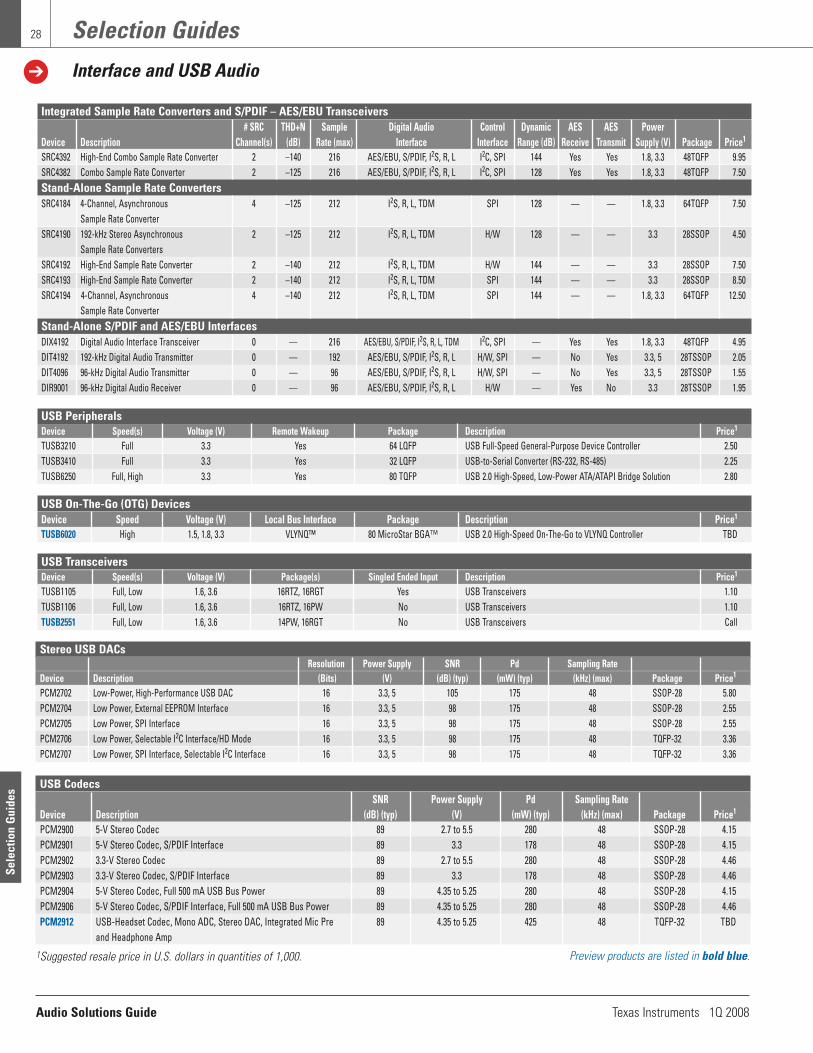
Audio Solutions Guide Texas Instruments 1Q 2008
Selection Guides
Interface and USB Audio
28
USB PeripheralsDevice Speed(s) Voltage (V) Remote Wakeup Package Description Price1
TUSB3210 Full 3.3 Yes 64 LQFP USB Full-Speed General-Purpose Device Controller 2.50TUSB3410 Full 3.3 Yes 32 LQFP USB-to-Serial Converter (RS-232, RS-485) 2.25TUSB6250 Full, High 3.3 Yes 80 TQFP USB 2.0 High-Speed, Low-Power ATA/ATAPI Bridge Solution 2.80
USB On-The-Go (OTG) DevicesDevice Speed Voltage (V) Local Bus Interface Package Description Price1
TUSB6020 High 1.5, 1.8, 3.3 VLYNQ™ 80 MicroStar BGA™ USB 2.0 High-Speed On-The-Go to VLYNQ Controller TBD
USB TransceiversDevice Speed(s) Voltage (V) Package(s) Singled Ended Input Description Price1
TUSB1105 Full, Low 1.6, 3.6 16RTZ, 16RGT Yes USB Transceivers 1.10TUSB1106 Full, Low 1.6, 3.6 16RTZ, 16PW No USB Transceivers 1.10TUSB2551 Full, Low 1.6, 3.6 14PW, 16RGT No USB Transceivers Call
Integrated Sample Rate Converters and S/PDIF – AES/EBU Transceivers # SRC THD+N Sample Digital Audio Control Dynamic AES AES Power
Device Description Channel(s) (dB) Rate (max) Interface Interface Range (dB) Receive Transmit Supply (V) Package Price1
SRC4392 High-End Combo Sample Rate Converter 2 –140 216 AES/EBU, S/PDIF, I2S, R, L I2C, SPI 144 Yes Yes 1.8, 3.3 48TQFP 9.95 SRC4382 Combo Sample Rate Converter 2 –125 216 AES/EBU, S/PDIF, I2S, R, L I2C, SPI 128 Yes Yes 1.8, 3.3 48TQFP 7.50 Stand-Alone Sample Rate Converters SRC4184 4-Channel, Asynchronous 4 –125 212 I2S, R, L, TDM SPI 128 — — 1.8, 3.3 64TQFP 7.50
Sample Rate Converter SRC4190 192-kHz Stereo Asynchronous 2 –125 212 I2S, R, L, TDM H/W 128 — — 3.3 28SSOP 4.50
Sample Rate Converters SRC4192 High-End Sample Rate Converter 2 –140 212 I2S, R, L, TDM H/W 144 — — 3.3 28SSOP 7.50 SRC4193 High-End Sample Rate Converter 2 –140 212 I2S, R, L, TDM SPI 144 — — 3.3 28SSOP 8.50 SRC4194 4-Channel, Asynchronous 4 –140 212 I2S, R, L, TDM SPI 144 — — 1.8, 3.3 64TQFP 12.50
Sample Rate Converter Stand-Alone S/PDIF and AES/EBU Interfaces DIX4192 Digital Audio Interface Transceiver 0 — 216 AES/EBU, S/PDIF, I2S, R, L, TDM I2C, SPI — Yes Yes 1.8, 3.3 48TQFP 4.95 DIT4192 192-kHz Digital Audio Transmitter 0 — 192 AES/EBU, S/PDIF, I2S, R, L H/W, SPI — No Yes 3.3, 5 28TSSOP 2.05 DIT4096 96-kHz Digital Audio Transmitter 0 — 96 AES/EBU, S/PDIF, I2S, R, L H/W, SPI — No Yes 3.3, 5 28TSSOP 1.55 DIR9001 96-kHz Digital Audio Receiver 0 — 96 AES/EBU, S/PDIF, I2S, R, L H/W — Yes No 3.3 28TSSOP 1.95
Stereo USB DACsResolution Power Supply SNR Pd Sampling Rate
Device Description (Bits) (V) (dB) (typ) (mW) (typ) (kHz) (max) Package Price1
PCM2702 Low-Power, High-Performance USB DAC 16 3.3, 5 105 175 48 SSOP-28 5.80PCM2704 Low Power, External EEPROM Interface 16 3.3, 5 98 175 48 SSOP-28 2.55PCM2705 Low Power, SPI Interface 16 3.3, 5 98 175 48 SSOP-28 2.55PCM2706 Low Power, Selectable I2C Interface/HD Mode 16 3.3, 5 98 175 48 TQFP-32 3.36PCM2707 Low Power, SPI Interface, Selectable I2C Interface 16 3.3, 5 98 175 48 TQFP-32 3.36
USB CodecsSNR Power Supply Pd Sampling Rate
Device Description (dB) (typ) (V) (mW) (typ) (kHz) (max) Package Price1
PCM2900 5-V Stereo Codec 89 2.7 to 5.5 280 48 SSOP-28 4.15PCM2901 5-V Stereo Codec, S/PDIF Interface 89 3.3 178 48 SSOP-28 4.15PCM2902 3.3-V Stereo Codec 89 2.7 to 5.5 280 48 SSOP-28 4.46PCM2903 3.3-V Stereo Codec, S/PDIF Interface 89 3.3 178 48 SSOP-28 4.46PCM2904 5-V Stereo Codec, Full 500 mA USB Bus Power 89 4.35 to 5.25 280 48 SSOP-28 4.15PCM2906 5-V Stereo Codec, S/PDIF Interface, Full 500 mA USB Bus Power 89 4.35 to 5.25 280 48 SSOP-28 4.46PCM2912 USB-Headset Codec, Mono ADC, Stereo DAC, Integrated Mic Pre 89 4.35 to 5.25 425 48 TQFP-32 TBD
and Headphone Amp
Preview products are listed in bold blue. 1Suggested resale price in U.S. dollars in quantities of 1,000.
Sele
ctio
n G
uide
s

Texas Instruments 1Q 2008 Audio Solutions Guide
29
Selection Guides
Processors
PWM Processors (PurePathTM) Frequency Dynamic Half Power Resolution
Device Description (MHz) Range (dB) THD+N at 1kHz (%) (Bits) Package Price1
TAS5010 Stereo Modulator Only 32 to 192 96 < 0.08 16, 20, 24 TQFP-48 3.00TAS5012 Stereo Modulator Only with Higher Dynamic Range 32 to 192 102 < 0.06 16, 20, 24 TQFP-48 5.55TAS5504A 4-Channel, EQ, Bass Management, Dynamic Range and Volume Control, HP Output 32 to 192 102 < 0.1 16, 20, 24 TQFP-64 3.00TAS5508B 8-Channel, EQ, Bass Management, Dynamic Range and Volume Control, HP Output 32 to 192 100 < 0.1 16, 20, 24 TQFP-64 5.00TAS5086 6-Channel, Bass Management, Tone and Volume Control 32 to 192 100 < 0.1 16, 20, 24 TSSOP-38 1.60TAS5518 8-Channel, Highest Dynamic Range, Record Line and HP Outputs, DSVC Adds 32 to 192 110 < 0.1 16, 20, 24 TQFP-64 7.95
24-dB Dynamic Range, EQ, Bass Management, Dynamic Range and Volume Control
Digital Audio ProcessorsInput Processing I/O Max
Device Description Digital I/O FS (kHz) Bits/Accumulator Resolution (Bits) Package Price1
TAS3103A Configurable Volume, Bass, Treble, Loudness, DRC, Mixing, Delay, 3-D Effects, 4/3 8 - 96 48/76 32 PSOP-32 4.15Biquad Filters
TAS3108 Fully-Programmable, 135-MHz, 48-Bit, 8-Channel Processor 8/8 16 - 192 48/76 24 TSSOP-38 5.10TAS3108IA Fully-Programmable, 135-MHz, 48-Bit, 8-Channel Processor (Automotive Qualified) 8/8 16 - 192 48/76 24 TSSOP-38 5.75
Digital Audio SoCsStereo Number of Number of Number of
Device Description Input MUX ADCs/DNR (dB) DACs/DNR (dB) PWMs/DNR Package Price1
TAS3204 Fully Programmable, 135-MHz, 48-Bit, 8-Channel Processor with Integrated Analog I/O 3:1 (x2) 4/102 4/105 — TQFP-64 6.15TAS3208 Fully Programmable, 135-MHz, 48-Bit, 8-Channel Processor with Integrated Analog I/O 10:1 2/93 6/96 — TQFP-100 6.50TAS3308 Fully Programmable, 135-MHz, 48-Bit, 8-Channel Processor with Integrated Analog I/O 10:1 2/96 — 6/100 dB TQFP-100 TBDTAS3202 Fully Programmable, 135-MHz, 48-Bit, 8-Channel Processor with Integrated Analog I/O 2:1 2/102 2/105 — TQFP-64 TBD
TMS320C67x™ DSP Generation — Floating-Point DSPsTypical Activity Voltage
RAM (Bytes) SPI/ Cycle Total Internal Power (W) (V) Price10
Device Data/Prog McBSP McASP DMA COM I2C MHz (ns) MFLOPS (Full Device Speed) Core I/O Package (100 u)TMS320C6720BRFP2004 32K/64K/384K6 — 2 dMAX2 — 2/2 200 5 1200 0.8 1.2 3.3 144 PQFP, 22mm 7.53TMS320C6712DGDP150 4K/4K/64K1 2 — 162 — — 150 6.7 900 0.7 1.2 3.3 272 BGA, 27mm 15.16TMS320C6722BRFP2003,4 32K/128K/384K6 — 2 dMAX — 2/2 200 5 1200 0.8 1.2 3.3 144 PQFP, 22mm 11.14TMS320C6722BRFPA2253,4,5 32K/128K/384K6 — 2 dMAX — 2/2 225 4.4 1350 0.8 1.2 3.3 144 PQFP, 22mm 12.94TMS320C6722BRFP2503,4 32K/128K/384K6 — 2 dMAX — 2/2 250 4 1500 0.9 1.2 3.3 144 PQFP, 22mm 12.94TMS320C6726BRFPA2253,4,5 32K/256K/384K6 — 378 dMAX — 2/2 225 4.4 1350 0.8 1.2 3.3 144 PQFP, 22mm 16.68TMS320C6726BRFP2664,5 32K/256K/384K7 — 37 dMAX — 2/2 266 3.75 1600 0.9 1.2 3.3 144 PQFP, 22mm 16.68TMS320C6713BPYP200 4K/4K/256K2 29 28 162 HPI/16 — 200 5 1200 1.0 1.2 3.3 208 TQFP, 28mm 20.95TMS320C6727BZDH250 32K/256K/384K — 3 dMAX UHPI 2/2 250 4 1500 1.2 1.2 3.3 256 BGA, 17mm 19.74 TMS320C6727BZDHA2503,4,5 32K/256K/384K6 — 3 dMAX UHPI 2/2 250 4 1500 1.0 1.2 3.3 256 BGA, 17mm 23.58TMS320C6727BZDH2753,4 32K/256K/384K6 — 3 dMAX UHPI 2/2 275 3.6 1650 1.0 1.2 3.3 256 BGA, 17mm 20.84TMS320C6727BZDH3003,4,9 32K/256K/384K6 — 3 dMAX UHPI 2/2 300 3.3 1800 1.1 1.2 3.3 256 BGA, 17mm 23.58TMS320C6727BZDH350 32K/256K/384K — 3 dMAX UHPI 2/2 350 2.9 2100 1.4 1.4 3.3 256 BGA, 17mm 32.29 TMS320C6701GJC150 64K/64K 2 — 4 HPI/16 — 120 6.7 900 1.3 1.8 3.3 352 BGA, 35mm 95.34TMSC6701GJC16719V 64K/64K 2 — 4 HPI/16 — 167 6 1000 1.4 1.9 3.3 352 BGA, 35mm 144.52
1 Format represents cache memory architecture: [data cache] /[program cache] / [unified cache]2 Enhanced DMA.3 Extended temperature versions available for C6722, C6726, C6727, C6713, C6711D DSPs.4 RFP and ZDH packages are Pb-Free. 5 The “A” designation is for industrial temperature range.6 Format represents program cache/program or data memory/ROM.7 McASP2 DIT only.8 The C6713 DSP can be configured to have up to three serial ports in various
McASP/McBSP combinations by not utilizing the HPI. Other configurable serial options include I2C and additional GPIO.
9 Also available in 256-pin BGA, 17-mm (GDH) package. Note: All devices include two timers.Note: Enhanced plastic and military DSP versions are available for selected DSPs.
Preview products are listed in bold blue.New products are listed in bold red.
Selection Guides
10 Prices are quoted in U.S. dollars and represent year 2008 suggested resalepricing. All prices are subject to change. Customers are advised to obtainthe most current and complete pricing information from TI prior to placingorders. TI may verify final pricing prior to accepting any order.
1Suggested resale price in U.S. dollars in quantities of 1,000. See page 22 for complementary power stages for PurePath™ PWM processors.

Audio Solutions Guide Texas Instruments 1Q 2008
Selection Guides
Processors
30
DaVinci™ Digital Media ProcessorsL1/ L2/ External Program/
Frequency SRAM SRAM ROM Memory Video Ports Serial Connectivity Data Voltage (V)Device CPU (MHz) (Bytes) (Bytes) (Bytes) I/F EDMA (Configurable) I/F I/F Storage Core I/O Package(s) Price4
TMS320DM6446BZWT C64x+™, 594 112K 64K 16K 1 16-/8-Bit 64 Ch 1 Input, ASP, I2C, USB 2.0, Async SRAM, 1.2 1.8/ 361 BGA, 39.50ARM9, (DSP) (DSP) (DSP) (ARM) EMIFA 1 Output SPI, VLYNQ™, DDR2 SDRAM, 3.3 16 x 16mmDaVinci 297 40K 1 32-/16-Bit 3 UARTs 10/100 EMAC NAND Flash,Video (ARM) (ARM) DDR2 SmartMedia/xD
TMS320DM6443BZWT C64x+, 594 112K 64K 16K 1 16-/8-Bit 64 Ch 1 Output ASP, I2C, USB 2.0, Async SRAM, 1.2 1.8/ 361 BGA, 33.85ARM9, (DSP) (DSP) (DSP) (ARM) EMIFA SPI, VLYNQ, DDR2 SDRAM, 3.3 16 x 16mmDaVinci 297 40K 1 32-/16-Bit 3 UARTs 10/100 EMAC NAND Flash,Video (ARM) (ARM) DDR2 SmartMedia/xD
TMS320DM6441ZWT C64x+, 513/405 112K 64K 16K 1 16-/8-Bit 64 Ch 1 Input, ASP, I2C, USB 2.0, Async SRAM, 1.2/ 1.8/ 361 BGA, 27.05ARM9, (DSP) (DSP) (DSP) (ARM) EMIFA 1 Output SPI, VLYNQ, DDR2 SDRAM, 1.05 3.3 16 x 16mmDaVinci 256/202 40K 1 32-/16-Bit 3 UARTs 10/100 EMAC NAND Flash,Video (ARM) (ARM) DDR2 SmartMedia/xD
TMX320DM64311 C64x+, 300 64K 64K 64K 1 8-Bit 64 Ch 1 Input McASP, I2C, 10/100 EMAC Async SRAM, 1.05 1.8/ 361 BGA 11.25DaVinci EMIFA, 1 UART, DDR2 SDRAM, 3.3 16 x 16mm,Video 1 16-Bit 1 McBSP, NAND Flash 376 BGA
DDR2 1 HECC 23 x 23mmTMX320DM64331 C64x+, 400 112K 128K 64K 1 8-Bit 64 Ch 1 Output McASP, 32-Bit PCI, Async SRAM, 1.05/ 1.8/ 361 BGA 15.75
DaVinci 500 EMIFA, 1 McBSP, VLYNQ, DDR2 SDRAM, 1.2 3.3 16 x 16mm, 16.65Video 600 1 16-/32-Bit I2C, 10/100 EMAC, NAND Flash 376 BGA 18.50
DDR2 1 UART 16-Bit HPI 23 x 23mmTMX320DM64351 C64x+, 400 112K 128K 64K 1 8-Bit 64 Ch 1 Input McASP, I2C, VLYNQ, Async SRAM, 1.05/ 1.8/ 361 BGA 16.30
DaVinci 500 EMIFA, 1 McBSP, 10/100 EMAC, DDR2 SDRAM, 1.2 3.3 16 x 16mm, 17.25Video 600 1 16-/32-Bit 2 UARTs, 16-Bit HPI NAND Flash 376 BGA 19.15
DDR2 1 HECC 23 x 23mmTMX320DM64371 C64x+, 400 112K 128K 64K 1 8-Bit 64 Ch 1 Input, McASP, I2C, 32-Bit PCI, Async SRAM, 1.05/ 1.8/ 361 BGA 22.05
DaVinci 500 EMIFA, 1 Output 1 HECC VLYNQ, DDR2 SDRAM, 1.2 3.3 16 x 16 mm, 23.35Video 600 1 16-/32-Bit 2 McBSPs, 10/100 EMAC, NAND Flash 376 BGA 25.93
DDR2 2 UARTs 16-Bit HPI 23 x 23 mmTMX320DM355 ARM9, 216 — — 8K 1 16-/8-Bit 64 Ch 1 Input, 3 SPI, USB 2.0 HS Async SRAM, 1.3 1.8/ 329 BGA 14.25
DaVinci 270 EMIFA, 1 Output 2 ASP, MDDR/DDR2 3.3 13 *13mm 16.90Video 1 16-Bit 3 UARTs, SDRAM,
MDDR/DDR2 I2C NAND Flash,SmartMedia/xD
TMX320DM647 C64x+, 720 32K/32K 256K 64K 1 16-/8-Bit 64 Ch 5 Video Ports 1 I2C, PCI/HPI, Async SRAM, 1.2/ 1.8/ 529 nFBGA 45.15DaVinci 900 EMIFA3 (Each Config- 1 SPI, VLYNQ, DDR2 SDRAM, 1.2 3.3 19 *19mm 63.20Video 1 32-/16-Bit urable as Dual 1 UART, 10/100/1000 NAND Flash,
DDR2 Capture, Single 1 McASP 3-pt Ethernet NOR FlashCapture, Display, Switch Subsys
TSI Capture) w/ 1 SGMII PtTMX320DM648 C64x+, 720 32K/32K 512K 64K 1 16-/8-Bit 64 Ch 5 Video Ports 2 I2C, PCI/HPI, Async SRAM, 1.2/ 1.8/ 529 nFBGA 56.45
DaVinci 900 EMIFA3 (Each Config- 1 SPI, VLYNQ, DDR2 SDRAM, 1.2 3.3 19 *19mm 74.50Video 1 32-/16-Bit urable as Dual 1 UART, 10/100/1000 NAND Flash,
DDR2 Capture, Single 1 McASP 3-pt Ethernet NOR FlashCapture, Display, 2 TSIP Switch Subsys
TSI Capture) w/ 2 SGMII Pts
New devices are listed in red. 1 Available in the ZDU (376-pin plastic BGA) and ZWT (361-pin Pb-free PBGA) packages.2 McBSP can be configured as an SPI peripheral.3 EMIFA does not support SDRAM.4 Prices are quoted in U.S. dollars and represent year 2007 suggested resale pricing. All prices are subject to change.
Customers are advised to obtain. New devices are listed in red.the most current and complete pricing information from TI prior to placing orders. TI may verify final pricing prior to accepting any order.
Sele
ctio
n G
uide
s

Texas Instruments 1Q 2008 Audio Solutions Guide
Selection Guides
Audio Clocks
31
Programmable Multiple PLL Clock Synthesizer Family with Fully Integrated Fan OutsCore Number Max. Fully Spread-
Supply I/O Number of Output Input Integrated Oppm Spectrum Support Temp. PeriodVoltage Voltage of Outputs Frequency Frequency VCXO Circuitry Frequency Clocking on Frequency Range Jitter
Device (V) (V) PLL (LVCMOS) (MHz) (MHz) Except Crystal Generation all Outputs Switching Programmability Package (°C) (pa) (typ)CDCE949 1.8 2.5 to 3.3 4 9 230 Crystal: 8 to 32 Yes Yes Yes Yes I2C and EEPROM TSSOP-24 –40 to 85 60
LVCMOS: Upto 150
CDCE937 1.8 2.5 to 3.3 3 7 230 Crystal: 8 to 32 Yes Yes Yes Yes I2C and EEPROM TSSOP-20 –40 to 85 60LVCMOS: Up
to 150CDCE925 1.8 2.5 to 3.3 2 5 230 Crystal: 8 to 32 Yes Yes Yes Yes I2C and EEPROM TSSOP-16 –40 to 85 60
LVCMOS: Upto 150
CDCE913 1.8 2.5 to 3.3 1 3 230 Crystal: 8 to 32 Yes Yes Yes Yes I2C and EEPROM TSSOP-14 –40 to 85 60LVCMOS: Up
to 150CDCEL949 1.8 1.8 4 9 230 Crystal: 8 to 32 Yes Yes Yes Yes I2C and EEPROM TSSOP-24 –40 to 85 60
LVCMOS: Upto 150
CDCEL937 1.8 1.8 3 7 230 Crystal: 8 to 32 Yes Yes Yes Yes I2C and EEPROM TSSOP-20 –40 to 85 60LVCMOS: Up
to 150CDCEL925 1.8 1.8 2 5 230 Crystal: 8 to 32 Yes Yes Yes Yes I2C and EEPROM TSSOP-16 –40 to 85 60
LVCMOS: Upto 150
CDCEL913 1.8 1.8 1 3 230 Crystal: 8 to 32 Yes Yes Yes Yes I2C and EEPROM TSSOP-14 –40 to 85 60LVCMOS: Up
to 150
Selection Guides

Audio Solutions Guide Texas Instruments 1Q 2008
Selection Guides
Analog Multiplexers and Switches
32
Analog Multiplexers and Switchesron ron Flatness ron Mismatch V+ V+ ON Time OFF Time
Device (max) (max) (max) (V) (min) (V) (max) (ns) (max) (ns) (max) Pin(s)/Package(s)SPSTTS5A3166 0.9 0.15 — 1.65 5.5 7 11.5 5/SC70, SOT-23, WCSP TS5A3167 0.9 0.15 — 1.65 5.5 7 11.5 5/SC70, SOT-23, WCSP TS5A4594 8 1.5 — 2.7 5.5 17 14 5/SC70, SOT-23 TS5A4595 8 1.5 — 2.7 5.5 17 14 5/SC70, SOT-23 TS5A4596 8 1.5 — 2.7 5.5 17 14 5/SC70, SOT-23 TS5A4597 8 1.5 — 2.7 5.5 17 14 5/SC70, SOT-23 TS5A1066 10 5 — 1.65 5.5 5.5 4.5 5/SC70, SOT-23, WCSP TS12A4514 20 4 — –0.3 13 125 60 8/SOIC TS12A4515 20 4 — –0.3 13 125 60 8/SOIC TS12A4516 25 3 — –0.3 13 85 50 8/SOIC TS12A4517 25 3 — –0.3 13 85 50 8/SOIC SPST x 2TS5A23166 0.9 0.25 0.1 1.65 5.5 7.5 11 8/US8, WCSP TS5A23167 0.9 0.25 0.1 1.65 5.5 7.5 11 8/US8, WCSP TS3A4741 0.9 0.4 0.05 1.65 3.6 14 9 8/MSOP TS5A2066 10 5 1 1.65 5.5 5.8 3.6 8/SM8, US8, WCSP SPST x 4TS3A4751 0.9 0.4 0.05 1.65 3.6 14 9 14/TSSOP SPDTTS5A6542 0.75 0.25 0.25 2.25 5.5 25 20 8/WCSP TS5A4624 0.9 0.25 0.1 1.65 5.5 22 8 6/SC70 TS5A3153 0.9 0.15 0.1 1.65 5.5 16 15 8/US8, WCSP TS5A3154 0.9 0.15 0.1 1.65 5.5 8 12.5 8/US8, WCSP TS5A3159A 0.9 0.25 0.1 1.65 5.5 30 20 6/SC70, SOT-23, WCSP TS5A3159 1.1 0.15 0.1 1.65 5.5 35 20 6/SC70, SOT-23 TS5A3160 0.9 0.25 0.1 1.65 5.5 6 13 6/SC70, SOT-23 TS5A3157 10 5 0.2 1.65 5.5 8.5 6.5 6/SC70, SOT-23, WCSP TS5A63157 10 2 0.14 1.65 5.5 5 3.4 6/SC70, SOT-23 TS5A2053 13.8 4.5 4.5 1.65 5.5 6.8 4.1 8/SM8, US8 SPDT x 2TS5A23159 0.9 0.25 0.1 1.65 5.5 13 8 10/MSOP, QFN TS5A23160 0.9 0.25 0.1 1.65 5.5 5.5 10 10/MSOP TS5A23157 10 4 (typ) 0.15 (typ) 1.65 5.5 5.7 3.8 10/MSOP, QFN SPDT x 4TS3A5018 10 7 0.8 1.65 3.6 8 6.5 16/SOIC, SSOP (QSOP), TSSOP, TVSOP, QFN SP3TTS5A3359 0.9 0.25 0.1 1.65 5.5 21 10.5 8/US8 TS5A3357 15 6.5 (typ) 0.1 (typ) 1.65 5.5 6.5 3.7 8/SM8, US8SP4T x 2TS3A5017 12 9 2 2.3 3.6 9.5 3.5 16/SOIC, SSOP (QSOP), TSSOP, TVSOP, QFN
Sele
ctio
n G
uide
s

Texas Instruments 1Q 2008 Audio Solutions Guide
Resources
Packaging
33
Package Type
Package Designator
Wafer ScalePackage
(WSP)
YEG, YEK, YEJ, YEA, YZA, YED, YNA
YZF,YZH
Small OutlineTransistorPackage(SOT23)
DBY, DCN, Thin SOT, DDC
Mini SmallOutline
Package(MSOP)
DGK, DGS
Small OutlineNo Leads
(SON)
DRD, DRB, DRC
Shrink SmallOutline
Package(SSOP)
DBQ, DB, DL
Quad FlatpackNo Leads
(QFN)
RGS, RGY, RGT, RGV,RGY, RHC, RGA, RGP,RGW, RGY, RGE, RGU,RHD, RGL, RGD, RHB,RGF, RHA, RTA, RGN,RGZ, RGQ, RGC, RHE,
RHF
Thin QuadFlatpack(TQFP)
PBS, PJT, PFB, PAG
Small OutlineTransistor(SOT223)
DCY, DCQ
Heat Sink Thin QuadFlatpack(HTQFP)
PHP, PAP
Small OutlineIntegrated
Circuit(SOIC)
D, DTH, DTC, DW, DWU
High-Performance Analog Packages
PackageType
PackageDesignator
Thin ShrinkSmall
OutlinePackage(TSSOP)
PW
PlasticDual-In-Line
Package(PDIP)
P, N, NT,NTD
Heat SinkSmall
OutlinePackage(HSOP)
DWP, DWD
Heat SinkThin Shrink
SmallOutline
Package(HTSSOP)
DDV
PowerSmall
OutlinePackage(PSOP3)
DKP (slug down),
DKD (slug up)
Ball GridArray(BGA)
ZAS, ZQE
Resources

Audio Solutions Guide Texas Instruments 1Q 2008
Resources
Tools
34
Samples and Evaluation Modules (EVMs)
TI offers free samples for more than 15,000 devices (shipped within 24 hours), which allows you to quickly test a variety of solutions for your audio design. EVMs allow you to determine how a specific product will operate in your system so you can deliver winning designs to market faster. TI also offers GUI software tools to easily start evaluating and designing with our latest products.
Consider these EVMs and associated software to experience a few of the latest audio solutions from TI:
• Regular- and nano-sized TPA2013D1 EVMs
• TPA3123D2 EVM
• TLV320AIC3106 EVM and GUI
Audio Selection Tool
With the audio selection tool, answer just a few questions to quicklynarrow your search for the right products for your design. The toolfeatures detailed decision trees for many TI audio products, including:
• Digital audio processors
• PurePath™ power amplifiers
• Audio converters
• Codecs
• Sample rate converters
Bookmark this link for the latest information on TI audio solutions: www.ti.com/audio
• Audio samples and evaluation modules • Product video casts
• End-equipment system block diagrams • Audio selection tool
• Application information • Product selection guides
Accelerate Your Audio Design with TI Tools and Resources
To get started, visit www.ti.com/audio and click the AudioSelection Tool link.
Reso
urce
s
Regular TPA2013D1 EVM
Get the samples and evaluation modules you need now. Visit: www.ti.com/audio
Nano TPA2013D1 EVM
TPA3123D2 EVM
TLV320AIC3106 EVM
Graphic User Interface
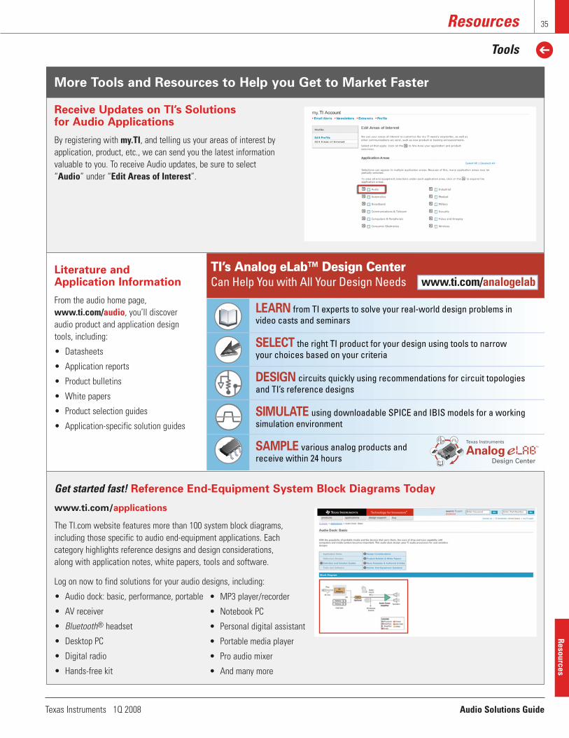
More Tools and Resources to Help you Get to Market Faster
Texas Instruments 1Q 2008 Audio Solutions Guide
Resources
Tools
35
Literature and Application Information
From the audio home page,www.ti.com/audio, you’ll discoveraudio product and application designtools, including:
• Datasheets
• Application reports
• Product bulletins
• White papers
• Product selection guides
• Application-specific solution guides
Receive Updates on TI’s Solutions for Audio Applications
By registering with my.TI, and telling us your areas of interest byapplication, product, etc., we can send you the latest informationvaluable to you. To receive Audio updates, be sure to select“Audio” under “Edit Areas of Interest”.
www.ti.com/applications
The TI.com website features more than 100 system block diagrams,including those specific to audio end-equipment applications. Eachcategory highlights reference designs and design considerations,along with application notes, white papers, tools and software.
Log on now to find solutions for your audio designs, including:
• Audio dock: basic, performance, portable
• AV receiver
• Bluetooth® headset
• Desktop PC
• Digital radio
• Hands-free kit
• MP3 player/recorder
• Notebook PC
• Personal digital assistant
• Portable media player
• Pro audio mixer
• And many more
Resources
Get started fast! Reference End-Equipment System Block Diagrams Today
TI’s Analog eLab™ Design Center Can Help You with All Your Design Needs
LEARN from TI experts to solve your real-world design problems in video casts and seminars
SELECT the right TI product for your design using tools to narrow your choices based on your criteria
DESIGN circuits quickly using recommendations for circuit topologies and TI’s reference designs
SIMULATE using downloadable SPICE and IBIS models for a working simulation environment
SAMPLE various analog products and receive within 24 hours
Texas Instruments
Design CenterAnalog
TM
www.ti.com/analogelab

To download these product selection guides, please visit:
PRSRT STDU.S. POSTAGE
PAIDDALLAS, TEXASPERMIT No. 2758
Texas Instruments Incorporated
14950 F.A.A. Blvd.
Fort Worth, Texas 76155
Address service requested
SLYY013B

IMPORTANT NOTICETexas Instruments Incorporated and its subsidiaries (TI) reserve the right to make corrections, modifications, enhancements, improvements,and other changes to its products and services at any time and to discontinue any product or service without notice. Customers shouldobtain the latest relevant information before placing orders and should verify that such information is current and complete. All products aresold subject to TI’s terms and conditions of sale supplied at the time of order acknowledgment.TI warrants performance of its hardware products to the specifications applicable at the time of sale in accordance with TI’s standardwarranty. Testing and other quality control techniques are used to the extent TI deems necessary to support this warranty. Except wheremandated by government requirements, testing of all parameters of each product is not necessarily performed.TI assumes no liability for applications assistance or customer product design. Customers are responsible for their products andapplications using TI components. To minimize the risks associated with customer products and applications, customers should provideadequate design and operating safeguards.TI does not warrant or represent that any license, either express or implied, is granted under any TI patent right, copyright, mask work right,or other TI intellectual property right relating to any combination, machine, or process in which TI products or services are used. Informationpublished by TI regarding third-party products or services does not constitute a license from TI to use such products or services or awarranty or endorsement thereof. Use of such information may require a license from a third party under the patents or other intellectualproperty of the third party, or a license from TI under the patents or other intellectual property of TI.Reproduction of TI information in TI data books or data sheets is permissible only if reproduction is without alteration and is accompaniedby all associated warranties, conditions, limitations, and notices. Reproduction of this information with alteration is an unfair and deceptivebusiness practice. TI is not responsible or liable for such altered documentation. Information of third parties may be subject to additionalrestrictions.Resale of TI products or services with statements different from or beyond the parameters stated by TI for that product or service voids allexpress and any implied warranties for the associated TI product or service and is an unfair and deceptive business practice. TI is notresponsible or liable for any such statements.TI products are not authorized for use in safety-critical applications (such as life support) where a failure of the TI product would reasonablybe expected to cause severe personal injury or death, unless officers of the parties have executed an agreement specifically governingsuch use. Buyers represent that they have all necessary expertise in the safety and regulatory ramifications of their applications, andacknowledge and agree that they are solely responsible for all legal, regulatory and safety-related requirements concerning their productsand any use of TI products in such safety-critical applications, notwithstanding any applications-related information or support that may beprovided by TI. Further, Buyers must fully indemnify TI and its representatives against any damages arising out of the use of TI products insuch safety-critical applications.TI products are neither designed nor intended for use in military/aerospace applications or environments unless the TI products arespecifically designated by TI as military-grade or "enhanced plastic." Only products designated by TI as military-grade meet militaryspecifications. Buyers acknowledge and agree that any such use of TI products which TI has not designated as military-grade is solely atthe Buyer's risk, and that they are solely responsible for compliance with all legal and regulatory requirements in connection with such use.TI products are neither designed nor intended for use in automotive applications or environments unless the specific TI products aredesignated by TI as compliant with ISO/TS 16949 requirements. Buyers acknowledge and agree that, if they use any non-designatedproducts in automotive applications, TI will not be responsible for any failure to meet such requirements.Following are URLs where you can obtain information on other Texas Instruments products and application solutions:Products ApplicationsAmplifiers amplifier.ti.com Audio www.ti.com/audioData Converters dataconverter.ti.com Automotive www.ti.com/automotiveDSP dsp.ti.com Broadband www.ti.com/broadbandClocks and Timers www.ti.com/clocks Digital Control www.ti.com/digitalcontrolInterface interface.ti.com Medical www.ti.com/medicalLogic logic.ti.com Military www.ti.com/militaryPower Mgmt power.ti.com Optical Networking www.ti.com/opticalnetworkMicrocontrollers microcontroller.ti.com Security www.ti.com/securityRFID www.ti-rfid.com Telephony www.ti.com/telephonyRF/IF and ZigBee® Solutions www.ti.com/lprf Video & Imaging www.ti.com/video
Wireless www.ti.com/wireless
Mailing Address: Texas Instruments, Post Office Box 655303, Dallas, Texas 75265Copyright 2008, Texas Instruments Incorporated