audio interface modules installation instructions
TRANSCRIPT

Communication and Audio Interface Modules Installation Instructions
© 2005-2011 SimplexGrinnell LP. All rights reserved. Specifications and other information shown were current as of publication and are subject to change without notice. Simplex and the Simplex logo are trademarks of Tyco International Ltd. and its affiliates and are used under license.
574-844 Rev. P
This publication describes the installation procedure for Transponder Interface Cards (TICs), Audio Riser Modules, and the Network Audio Riser Controller Module for installation in 4100U and 4100ES Fire Alarm Control Panels. This product is compatible with 4100U and 4100ES Fire Alarm Control Panels (FACP). This publication also includes connections that provide the Non-Alarm Audio (NAA) Interface feature. IMPORTANT: Verify FACP System Programmer, Executive, and Slave Software
compatibility when installing, or replacing system components. Refer to the Technical Support Information and Downloads website for compatibility information.
Topic See Page #
Cautions and Warnings 2 TICs and Audio Riser Modules 3 System Guidelines 8 Network Audio Riser Controller Module 9 Configuration 10 Mounting 12 Wiring 13 Digital Audio Riser Module (566-407,-833) 21 Non-Alarm Audio (NAA) Interface 23 Field Replacement of the Digital Audio Riser Module (566-243) 26 Digital Audio PDI Termination Plug 27
Introduction
In this Publication

2
Cautions and Warnings
READ AND SAVE THESE INSTRUCTIONS- Follow the instructions in this installation manual. These instructions must be followed to avoid damage to this product and associated equipment. Product operation and reliability depend upon proper installation.
DO NOT INSTALL ANY SIMPLEX® PRODUCT THAT APPEARS DAMAGED- Upon unpacking your Simplex product, inspect the contents of the carton for shipping damage. If damage is apparent, immediately file a claim with the carrier and notify an authorized Simplex product supplier.
ELECTRICAL HAZARD - Disconnect electrical field power when making any internal adjust-ments or repairs. All repairs should be performed by a representative or authorized agent of your local Simplex product supplier.
EYE SAFETY HAZARD - Under certain fiber optic application conditions, the optical output of this device may exceed eye safety limits. Do not use magnification (such as a microscope or other focusing equipment) when viewing the output of this device.
STATIC HAZARD - Static electricity can damage components. Handle as follows: • Ground yourself before opening or installing components. • Prior to installation, keep components wrapped in anti-static material at all times.
FCC RULES AND REGULATIONS – PART 15 - This equipment has been tested and found to comply with the limits for a Class A digital device pursuant to Part 15 of the FCC Rules. These limits are designed to provide reasonable protection against harmful interference when the equipment is operated in a commercial environment. This equipment generates, uses, and can radiate radio frequency energy and, if not installed and used in accordance with the instruction manual, may cause harmful interference to radio communications. Operation of this equipment in a residential area is likely to cause harmful interference in which case the user will be required to correct the interference at his own expense. SYSTEM REACCEPTANCE TEST AFTER SOFTWARE CHANGES - To ensure proper system operation, this product must be tested in accordance with NFPA 72® after any programming operation or change in site-specific software. Reacceptance testing is required after any change, addition or deletion of system components, or after any modification, repair or adjustment to system hardware or wiring. All components, circuits, system operations, or software functions, known to be affected by a change, must be 100% tested. In addition, to ensure that other operations are not inadvertently affected, at least 10% of initiating devices that are not directly affected by the change, up to a maximum of 50 devices, must also be tested and proper system operation verified. NFPA 72® is a registered trademark of the National Fire Protection Association.
Cautions and Warnings
3
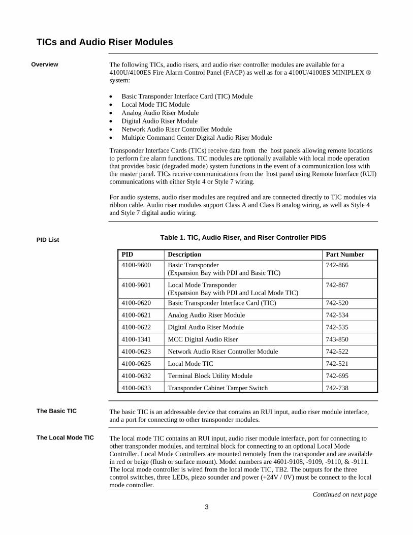
The following TICs, audio risers, and audio riser controller modules are available for a 4100U/4100ES Fire Alarm Control Panel (FACP) as well as for a 4100U/4100ES MINIPLEX ® system: • Basic Transponder Interface Card (TIC) Module • Local Mode TIC Module • Analog Audio Riser Module • Digital Audio Riser Module • Network Audio Riser Controller Module • Multiple Command Center Digital Audio Riser Module
Transponder Interface Cards (TICs) receive data from the host panels allowing remote locations to perform fire alarm functions. TIC modules are optionally available with local mode operation that provides basic (degraded mode) system functions in the event of a communication loss with the master panel. TICs receive communications from the host panel using Remote Interface (RUI) communications with either Style 4 or Style 7 wiring. For audio systems, audio riser modules are required and are connected directly to TIC modules via ribbon cable. Audio riser modules support Class A and Class B analog wiring, as well as Style 4 and Style 7 digital audio wiring.
Table 1. TIC, Audio Riser, and Riser Controller PIDS
PID Description Part Number 4100-9600 Basic Transponder
(Expansion Bay with PDI and Basic TIC) 742-866
4100-9601 Local Mode Transponder (Expansion Bay with PDI and Local Mode TIC)
742-867
4100-0620 Basic Transponder Interface Card (TIC) 742-520
4100-0621 Analog Audio Riser Module 742-534
4100-0622 Digital Audio Riser Module 742-535
4100-1341 MCC Digital Audio Riser 743-850
4100-0623 Network Audio Riser Controller Module 742-522
4100-0625 Local Mode TIC 742-521
4100-0632 Terminal Block Utility Module 742-695
4100-0633 Transponder Cabinet Tamper Switch 742-738
The basic TIC is an addressable device that contains an RUI input, audio riser module interface, and a port for connecting to other transponder modules.
The local mode TIC contains an RUI input, audio riser module interface, port for connecting to other transponder modules, and terminal block for connecting to an optional Local Mode Controller. Local Mode Controllers are mounted remotely from the transponder and are available in red or beige (flush or surface mount). Model numbers are 4601-9108, -9109, -9110, & -9111. The local mode controller is wired from the local mode TIC, TB2. The outputs for the three control switches, three LEDs, piezo sounder and power (+24V / 0V) must be connect to the local mode controller.
Continued on next page
TICs and Audio Riser Modules
Overview
PID List
The Basic TIC
The Local Mode TIC

4
TB1
CH2SEC-
SEC+
SHLD
PRI-
PRI+
CH1/DARSEC-
SEC+
SHLD
PRI-
PRI+
16
15
2
LED1CH2
LED2CH1/DAR
1
SEC 1
TB3TB2
1
P2
1
TB1
21
SEC 2DAR CHANNEL OUT NAA IN
NAA OUT
NAAVOLUME
R4
SW1
LED1
LED2
LED3LED4
DAR GROUND FAULTSEARCH ACTIVE
PDI RECEIVEENABLE
PRIMARY RECEIVE
SECONDARY RECEIVE
DIGITALRISER
ON-ENABLENAA
1234
SW2LSBMSB
1234
LINE25V
70V
SHLDPRI 1
A local mode TIC acts as a controller for the transponder cabinet if the TIC loses communication with the Master Controller. When operating in local mode, an alarm on any fire alarm input circuit will cause all alarm notification appliance circuits to activate. Relays and other auxiliary control outputs will not activate. The local mode controller is limited to alarm functions.
Figure 1. TICs and Audio Riser Modules
Table 2. Environmental Specifications
Environmental Specifications (all PIDs)
Operating Temperature 32° to 120° F (0° to 49° C)
Humidity Up to 93% relative humidity at 90° F (32° C)
Continued on next page
TICs and Audio Riser Modules, Continued
The Local Mode TIC
Illustrations
4100-0620 BASIC TIC
4100-0625 LOCAL MODE TIC
4100-0621 ANALOG
AUDIO RISER
4100-0622 DIGITAL AUDIO RISER
4100-1314 MCC DIGITAL AUDIO RISER

5
TIC module LEDs provide the following status information: LED1. Illuminates to indicate communication loss with the host panel.
LED2. Illuminates when an RUI ground fault search is active.
LED3. Illuminates when Local Mode is active (4100-0625 Local Mode TIC only).
LED4. Illuminates to indicate an RUI Style 7 primary trouble.
LED5. Illuminates to indicate an RUI Style 7 secondary trouble.
Table 3. TIC (4100-0620, -0625) Specifications
Electrical Specifications
Input voltage 18-33 VDC
Output voltage 8 V @ 1 A; 100 mV p-p ripple
Input Current
87 mA maximum with no attachments (no 8V load) (-0625) only)112 mA maximum with local mode annunciator (no 8V load)
With 100 mA load on 8V output – 130 mA @ 24 VDC, 140 mA maximum over range With 300 mA load on 8V output – 210 mA @ 24 VDC, 250 mA maximum over range With 1.0 A load on 8V output – 500 mA @ 24 VDC, 650 mA maximum over range
Continued on next page
TICs and Audio Riser Modules, Continued
TIC LEDs
TIC Specifications
6
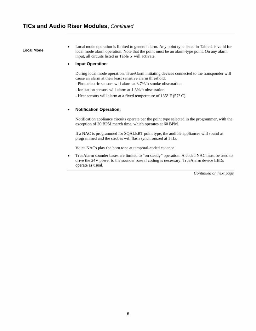
• Local mode operation is limited to general alarm. Any point type listed in Table 4 is valid for
local mode alarm operation. Note that the point must be an alarm-type point. On any alarm input, all circuits listed in Table 5 will activate.
• Input Operation: During local mode operation, TrueAlarm initiating devices connected to the transponder will cause an alarm at their least sensitive alarm threshold. - Photoelectric sensors will alarm at 3.7%/ft smoke obscuration - Ionization sensors will alarm at 1.3%/ft obscuration - Heat sensors will alarm at a fixed temperature of 135° F (57° C).
• Notification Operation: Notification appliance circuits operate per the point type selected in the programmer, with the exception of 20 BPM march time, which operates at 60 BPM. If a NAC is programmed for SQALERT point type, the audible appliances will sound as programmed and the strobes will flash synchronized at 1 Hz. Voice NACs play the horn tone at temporal-coded cadence.
• TrueAlarm sounder bases are limited to “on steady” operation. A coded NAC must be used to drive the 24V power to the sounder base if coding is necessary. TrueAlarm device LEDs operate as usual.
Continued on next page
TICs and Audio Riser Modules, Continued
Local Mode

7
Table 4. Alarm Input Devices
Point Type Description Curr. Lim. Short
FIRE Fire alarm (generic) Alarm Alarm WATER Waterflow switch Alarm Alarm HEAT* Heat detector Alarm Alarm DUCT* Duct detector Alarm Alarm FLAME Flame detector Alarm Alarm PULL Pull station Alarm Alarm SMOKE* Smoke detector Alarm Alarm VSMOKE* Verified smoke detector Alarm Alarm EMERG Combination fire/emergency Supv Alarm SFIRE Combination smoke/fire Alarm Alarm VSFIRE Verified combination smoke/fire Alarm Alarm SPULL Combination smoke/pull Alarm Alarm VSPULL Combination verified smoke/pull Alarm Alarm S2STAGE 2-stage monitor Alarm Alarm WSO Combination waterflow/tamper Supv Alarm WSC Combination waterflow/tamper Normal Alarm GVMON* Generic verified monitor Alarm Alarm STYLEC Style-C monitor Alarm Trouble GENFS Generic fire/supervisory (normally open) Supv Alarm SUPDET Suppression agent monitor zone Alarm Alarm SUPDUMP Suppression agent manual dump Alarm - SUPPRES Suppression pressure switch monitor Alarm Trouble
Table 5. Notification Appliance Circuit Types
Point Type Description SSIGNAL Alarm signal (will activate to Programmer specified default coding) RSIGNAL Alarm signal (will activate to Programmer specified default coding) SVISUAL Visual signal (will activate on steady) RVISUAL Visual signal (will activate on steady) SPEAKER Speaker circuit (will turn on steady – temporal horn tone from local tone
generator) SQALERT Signal/Visual on until silence (horn will activate on steady) SSYNVIS Strobes on until silence RSYNVIS Strobes on until reset
All TrueAlert visual devices will code according to their configuration before local mode activated (no virtual NAC support)
TICs and Audio Riser Modules, Continued Local Mode

8
• All wiring is 18 AWG (0.8231 mm2) (minimum) and 12 AWG (3.309 mm2) (maximum).
• All wiring is supervised and power-limited.
• All wiring that leaves the building requires overvoltage protection. Install the module inside an UL-Listed electrical box wherever wire enters or exits the building. A maximum of four 2081-9044 modules may be connected to one channel. The 2081-9044 is rated for 200 mA (maximum).
• For Class B (Style 4) operation: - The maximum distance to any device is 2,500 feet (762 m). - “T” taps are allowed. - Total maximum cable load is 10,000 ft (3,048 m), including t-taps and all parallel c connections. Use .29 pF/ Ft shielded cable to meet capacitance spec.
• For Style 4, 6 or 7 operation: - The maximum allowed line-to-line capacitance (“+” to “-” terminals) is 0.58 uF. - For applications with shielded wire, be sure that the total capacitance from line to line plus the shield to either line is no more than 0.58 uF.
• For Class A (Style 6 or Style 7) operation, the maximum loop distance is 2,500 feet (762 m). “T” taps are not allowed.
• RUI comms are wired to remote cabinets from the CPU motherboard to the transponder interface cards: 4100-0620 (566-093) or 4100-0625 (566-094).
• Transponder interface cards operate with a single open or a single short circuit when wired Class A (Style 7).
• The master control panel must be a 4100U Fire Alarm Control Panel or a 4100 ES Fire Alarm Control Panel.
• If 4602 and 4603 serial annunciators are present, circuit may be Style 4 or Style 6. Annunciators do not isolate a short circuit fault, making Style 7 not possible.
• Up to 4 RUI cards in the 4100 Control Panel can be used for distributing transponder wiring in different directions or for supporting different wiring requirements.
• Up to 31 transponders can be controlled from the 4100 Control Panel, and can be distributed as required among the RUI cards.
System Guidelines
RUI Guidelines

9
An audio network contains one node with an audio controller module (4100-1210 Analog Controller Board or 4100-1211 [or -1311] Digital Controller Board), and local analog or digital amplifiers. Some configurations may have an audio controller module located in a transponder end node; for example, an application with backup local audio in a non-head end node or an application with distributed microphones. Typically, the other nodes only contain amplifiers, the audio riser interface (a 4100-0621 Analog Audio Riser, a 4100-0622 Digital Audio Riser or a 4100-1341 MCC Digital Audio Riser), and the 4100-0623 Network Audio Riser Controller Module. The 4100-0623 Network Audio Riser Controller Module supports audio interconnections when connected to 4100-0621 Analog Audio Risers, 4100-0622 Digital Audio Risers or 4100-1341 MCC Digital Audio Risers. It is a version of the Basic TIC that doesn’t have RUI input. It communicates via internal communications and is used to control audio riser interface modules in network nodes that are stand-alone fire alarm control panels.
Figure 2 shows DIP switch, LED, and connector locations on the 4100-0623 Network Audio Riser Controller Module.
Figure 2. Network Audio Riser Controller Module
Table 6. Network Audio Riser Controller Specifications
Electrical Specifications (4100-0623)
Input voltage 18-33 VDC
Input current 35 mA maximum
Electrical Specifications (4100-0621)
Input voltage 18-33 VDC
Input current 15 mA maximum
Network Audio Riser Controller Module
Audio Network Configuration
Locations on the Network Audio Riser Controller Module
Network Audio Riser Controller Module Specifications
SW1. Baud rate/device address
DIP switch
LED1. Illuminates to indicate
communication loss with the CPU
P3. Audio riser module connector

10
The TIC and all other modules to be mounted in the transponder cabinet and attached expansion bays must be configured to operate correctly in the system via their DIP switch and jumper ports. This section describes the hardware configuration for TICs and the Network Audio Riser Controller Module.
The TIC and Network Audio Riser Controller Module device addresses are set via DIP switch SW1, which is a bank of eight switches. From left to right (see Figure 3,) these switches are designated as SW1-1 through SW1-8. The function of these switches is as follows:
• SW1-1. Set this switch to ON.
• SW1-2 through SW1-8. These switches select the module’s address. Refer to Table 7 for a complete list of the switch settings for all of the possible module addresses.
Note: You must set these switches to the value assigned to the module by the Programmer.
FigureTag FD4-844-01
1 8 7 6 5 4 3 2
Figure 3. DIP Switch SW1
Continued on next page
Configuration
Overview
Setting the Address
ON
OFF
DIP Switches SW1-2 through SW1-8 set the Card or Module Address. Figure 4 shows an Address of 3.
4100 Comm. Baud Rate. Switch
(SW1-1)Must Be Set to
ON

11
Table 7. TIC & Network Audio Riser Controller Module Addresses
Configuration, Continued
Setting the Address,
Address SW 1-2 SW 1-3 SW 1-4 SW 1-5 SW 1-6 SW 1-7 SW 1-8 Address SW 1-2 SW 1-3 SW 1-4 SW 1-5 SW 1-6 SW 1-7 SW 1-8
1 ON ON ON ON ON ON OFF 61 ON OFF OFF OFF OFF ON OFF 2 ON ON ON ON ON OFF ON 62 ON OFF OFF OFF OFF OFF ON 3 ON ON ON ON ON OFF OFF 63 ON OFF OFF OFF OFF OFF OFF 4 ON ON ON ON OFF ON ON 64 OFF ON ON ON ON ON ON 5 ON ON ON ON OFF ON OFF 65 OFF ON ON ON ON ON OFF 6 ON ON ON ON OFF OFF ON 66 OFF ON ON ON ON OFF ON 7 ON ON ON ON OFF OFF OFF 67 OFF ON ON ON ON OFF OFF 8 ON ON ON OFF ON ON ON 68 OFF ON ON ON OFF ON ON 9 ON ON ON OFF ON ON OFF 69 OFF ON ON ON OFF ON OFF
10 ON ON ON OFF ON OFF ON 70 OFF ON ON ON OFF OFF ON 11 ON ON ON OFF ON OFF OFF 71 OFF ON ON ON OFF OFF OFF 12 ON ON ON OFF OFF ON ON 72 OFF ON ON OFF ON ON ON 13 ON ON ON OFF OFF ON OFF 73 OFF ON ON OFF ON ON OFF 14 ON ON ON OFF OFF OFF ON 74 OFF ON ON OFF ON OFF ON 15 ON ON ON OFF OFF OFF OFF 75 OFF ON ON OFF ON OFF OFF 16 ON ON OFF ON ON ON ON 76 OFF ON ON OFF OFF ON ON 17 ON ON OFF ON ON ON OFF 77 OFF ON ON OFF OFF ON OFF 18 ON ON OFF ON ON OFF ON 78 OFF ON ON OFF OFF OFF ON 19 ON ON OFF ON ON OFF OFF 79 OFF ON ON OFF OFF OFF OFF 20 ON ON OFF ON OFF ON ON 80 OFF ON OFF ON ON ON ON 21 ON ON OFF ON OFF ON OFF 81 OFF ON OFF ON ON ON OFF 22 ON ON OFF ON OFF OFF ON 82 OFF ON OFF ON ON OFF ON 23 ON ON OFF ON OFF OFF OFF 83 OFF ON OFF ON ON OFF OFF 24 ON ON OFF OFF ON ON ON 84 OFF ON OFF ON OFF ON ON 25 ON ON OFF OFF ON ON OFF 85 OFF ON OFF ON OFF ON OFF 26 ON ON OFF OFF ON OFF ON 86 OFF ON OFF ON OFF OFF ON 27 ON ON OFF OFF ON OFF OFF 87 OFF ON OFF ON OFF OFF OFF 28 ON ON OFF OFF OFF ON ON 88 OFF ON OFF OFF ON ON ON 29 ON ON OFF OFF OFF ON OFF 89 OFF ON OFF OFF ON ON OFF 30 ON ON OFF OFF OFF OFF ON 90 OFF ON OFF OFF ON OFF ON 31 ON ON OFF OFF OFF OFF OFF 91 OFF ON OFF OFF ON OFF OFF 32 ON OFF ON ON ON ON ON 92 OFF ON OFF OFF OFF ON ON 33 ON OFF ON ON ON ON OFF 93 OFF ON OFF OFF OFF ON OFF 34 ON OFF ON ON ON OFF ON 94 OFF ON OFF OFF OFF OFF ON 35 ON OFF ON ON ON OFF OFF 95 OFF ON OFF OFF OFF OFF OFF 36 ON OFF ON ON OFF ON ON 96 OFF OFF ON ON ON ON ON 37 ON OFF ON ON OFF ON OFF 97 OFF OFF ON ON ON ON OFF 38 ON OFF ON ON OFF OFF ON 98 OFF OFF ON ON ON OFF ON 39 ON OFF ON ON OFF OFF OFF 99 OFF OFF ON ON ON OFF OFF 40 ON OFF ON OFF ON ON ON 100 OFF OFF ON ON OFF ON ON 41 ON OFF ON OFF ON ON OFF 101 OFF OFF ON ON OFF ON OFF 42 ON OFF ON OFF ON OFF ON 102 OFF OFF ON ON OFF OFF ON 43 ON OFF ON OFF ON OFF OFF 103 OFF OFF ON ON OFF OFF OFF 44 ON OFF ON OFF OFF ON ON 104 OFF OFF ON OFF ON ON ON 45 ON OFF ON OFF OFF ON OFF 105 OFF OFF ON OFF ON ON OFF 46 ON OFF ON OFF OFF OFF ON 106 OFF OFF ON OFF ON OFF ON 47 ON OFF ON OFF OFF OFF OFF 107 OFF OFF ON OFF ON OFF OFF 48 ON OFF OFF ON ON ON ON 108 OFF OFF ON OFF OFF ON ON 49 ON OFF OFF ON ON ON OFF 109 OFF OFF ON OFF OFF ON OFF 50 ON OFF OFF ON ON OFF ON 110 OFF OFF ON OFF OFF OFF ON 51 ON OFF OFF ON ON OFF OFF 111 OFF OFF ON OFF OFF OFF OFF 52 ON OFF OFF ON OFF ON ON 112 OFF OFF OFF ON ON ON ON 53 ON OFF OFF ON OFF ON OFF 113 OFF OFF OFF ON ON ON OFF 54 ON OFF OFF ON OFF OFF ON 114 OFF OFF OFF ON ON OFF ON 55 ON OFF OFF ON OFF OFF OFF 115 OFF OFF OFF ON ON OFF OFF 56 ON OFF OFF OFF ON ON ON 116 OFF OFF OFF ON OFF ON ON 57 ON OFF OFF OFF ON ON OFF 117 OFF OFF OFF ON OFF ON OFF 58 ON OFF OFF OFF ON OFF ON 118 OFF OFF OFF ON OFF OFF ON 59 ON OFF OFF OFF ON OFF OFF 119 OFF OFF OFF ON OFF OFF OFF 60 ON OFF OFF OFF OFF ON ON

12
TICs, Audio Riser Modules, and Network Audio Riser Controller Modules are 4” X 5” modules and are mounted per the following information. IMPORTANT: The TIC or Network Audio Riser Controller Module should be
mounted in the upper left position of the bay. The audio riser module must be mounted directly below the TIC or Network Audio Riser Controller Module.
1. Screw two standoffs and washers to the appropriate holes in the back of the cabinet.
These holes must line up with the screw holes in the 4 X 5 card. See Figure 4.
2. Plug the 4” X 5” card into the top left PDI connector (P8).
3. Secure the top of the card to the standoffs with two #6 torx screws and washers. Note: Figure 4 is a general-purpose illustration that applies to most
4” X 5” cards.
Figure 4. TIC or Network Audio Riser Controller Module Mounting
Mounting
Mounting Instructions
TIC OR NETWORK AUDIO RISER CONTROLLER MODULE
STANDOFFS
#6 SCREWS
WASHERS
PDI CONNECTOR (reverse side)
PDI
SCREW RETAINERS

13
4100 POWER DISTRIBUTION INTERFACEASSY 566-084
4100 POWER DISTRIBUTION INTERFACEASSY 566-084
LED4
SW1
LED1
TB2
PRI
LED2
P1
P3
LED5
TB3
SECRUI
TMPR SW24C INPUT SHLD
4100COMMLOSSRUIG.F.
SEARCH
AUDIO RISER CARD
HARNESS734-008
TI
SPSOR
RPSC
PDI 1
PDI 2
HARNESS734-078
P1
P6
POWER/COMM
Connectors withWhite Wire go to P3
HARNESS 733-525
Connectors withBlue Wire go to P2
Use Figure 5 to connect the TIC to a motherboard in another bay.
Figure 5. TIC/Motherboard Interconnections
Continued on next page
Wiring
TIC/Motherboard Interconnections
PDI Jumpers P4 and P5 on the PDI must be configured to provide power to the TIC. --- If there is a Power Supply in Bay 1,
• Set Jumpers P4 and P5 in Bay 1 to Positions 2 and 3. --- If there is no Power Supply in Bay 1 with the TIC, you must obtain
power from Bay 2 or Bay 3. Option 1
• Set Jumpers P4 and P5 in Bay 1 to Positions 1 and 2. • Connect one end of Harness 734-008 to Power/Comm
plug on the SPS or RPS (P6) (or P2 on XPS) located in Bay 2 or Bay 3. Connect the other end of the harness to P1 in Bay 1.
Option 2 • Set Jumpers P4 and P5 in Bay 1 to Positions 1 and 2. • Set Jumpers P4 and P5 to Positions 2 and 3 in bay with
power supply that will provide power to the TIC in Bay 1. • Connect one end of Harness 734-008 to P2 or P3 in bay
that will provide power to the TIC in Bay 1. Connect the other end of the harness to P1 in Bay 1.

14
The TIC (except for the Network Audio Riser Controller Module) must be connected to the host panel via RUI cabling. This section explains how to wire the two together, and how to set up a system with multiple transponders connected to the same host panel.
RUI cabling can be accomplished either through Class A or Class B wiring. Class A wiring allows transponder cabinets to communicate with the FACP even in the event of an open circuit somewhere in the loop. Class A wiring requires that two wires are routed from the CPU motherboard to each TIC, and then back again to the CPU motherboard. Class B wiring allows “T” tapping, and therefore requires less wiring distance per installation than Class A. Additionally, Class B wiring does not require end-of-line resistors, because each TIC communicates directly to the CPU. Note: Use supplied ferrite beads with TICs. Loop wires once through the supplied
ferrite bead(s) as shown in Figure 6.
Figure 6. Loop Wiring Through Bead as Shown Figure 7 shows both types of wiring.
TRANSPONDER INTERFACEASSY 566-094
MSB
LSB
LED1
AD
DR
ES
S
LED3
PRI
B+ B- SHLD A+ A-
SECRUI
SHLD
LED4 LED5
LED2
P1
P2 P3
RUI
P9
P1
1 2 3TRANSPONDER INTERFACEASSY 566-094
MSB
LSB
LED1
AD
DR
ES
S
LED3
PRI SECRUI
SHLD
LED4 LED5
LED2
P1
P2
Figure 7. TIC Wiring to the Host Panel
Continued on next page
Wiring, Continued
Overview
RUI Wiring Configurations
DASHED LINES ARE FOR CLASS A OPERATION
FERRITE BEADS (required)
• Wire size must be between 18 AWG (0.8231 mm2) and 12 AWG (3.309 mm2).
• Maximum wiring distance: 2,500 feet (762 m).
• Maximum “T” tapping length: 10,000 feet (3,048 m).
• Maintain correct polarity on terminal connections.
• Do not loop wires under terminals. • Use ferrite beads as shown.
CPU MOTHERBOARD 566-227

15
This section describes the Class A and Class B connections from audio controllers to audio risers, which in turn connect to a TIC or Network Audio Riser Controller Module. Wiring configurations are shown for both analog and digital controllers and risers.
Figure 8 is an illustration of Class A and Class B analog wiring from the analog audio controller to audio risers connected to TICs or the Network Audio Riser Controller Module.
DASHEDLINES ARE
FOR CLASS AOPERATION
4100-0620BASIC TIC(566-093)
OR 4100-0625LOCAL
MODE TIC(566-094)
4100-0620BASIC TIC(566-093)
OR 4100-0625LOCAL
MODE TIC(566-094)
4100-0621ANALOGAUDIORISER
(566-242)
4100-1210ANALOGAUDIO
CONTROLLER(566-218)
TB1RISER 1
1 10
RISER 2
S A A S A A
HARNESS733-997
P3
P2
Node 1Miniplex
Transponder
Node 1Host Panel
Node 2Control Panel
Node 2Miniplex
Transponder
4100-0623AUDIO RISERCONTROLLER
MODULE(566-249)
4100-0621ANALOGAUDIORISER
(566-242)
HARNESS733-997
P3
P2
4100-0621ANALOGAUDIORISER
(566-242)
HARNESS733-997
P3
P2
TB1RISER 1
1 10
RISER 2
SSEC PRI SEC PRI
S TB1RISER 1
1 10
RISER 2
SSEC PRI SEC PRI
S TB1RISER 1
1 10
RISER 2
SSEC PRI SEC PRI
S
Figure 8. Analog Interconnections
Continued on next page
Wiring, Continued
Overview
Analog Interconnections
1. Leave the 4.7 K, ½ W resistors (378-056; yellow/violet/red) on the “+” to “-” terminals of unused contacts. 2. All wiring is 18 AWG (0.8321 mm2) to 14 AWG (2.081 mm2), twisted-shielded pair. 3. Audio wiring is not to be mixed in the same jacket with other wiring (including other audio wiring). 4. AC voltage rating: 10 VRMS (maximum) 5. DC voltage rating: 1 VDC (maximum) 6. Maximum number of analog interface cards per audio riser: 31. 7. All wiring that leaves the building requires the 2081-9044 Overvoltage Protector at each entry or exit to the building. 8. Maximum wire distance: 10,000 feet (3,048 meters). 9. Wiring must be free of all grounds. 10. Set audio input card jumpers as shown in “Configuring the Audio Input Card.” 11. All riser wiring is supervised and power-limited.

16
The 4100U or 4100ES may be connected to the 4100 Legacy Audio Controller via the 4100U Audio Riser and the Network input on the Legacy Controller. The 4100U and 4100ES use a 10VRMS Analog Audio riser. In order to interface to a legacy 4100 Audio Controller Network input, an isolation/step-down transformer must be used. This is an existing product, the Audio Isolator Assembly, PN 742-302. The setup is slightly different from the instructions that are supplied with the module. Following are the modified installation instructions:
1. Connect the incoming nominal 10 VRMS 4100U/4100ES Audio Riser wiring to TB1 on the audio isolator. If the installation requires IN and OUT wiring, two wires may be installed under each screw of TB1. Note: The in and out wiring must be two separate wires. Do not loop the
wire around the TB1 screws. 2. If there is only one audio wire pair coming into the panel, isolate and tape back the shield
with high quality electrical tape. 3. If the installation requires IN and OUT wiring, install as indicated in Step 1 above,
connect the shields of the incoming and outgoing wires together to maintain continuity of the shield. The preferable method is to twist the shields together, solder and cover with a high quality electrical tape.
Figure 9. Audio Board Controller Configuration
Follow Steps 1 through 5 and Figure 9 to properly align the audio controller board after installing the audio isolator.
1. Ensure the jumper wire on the isolator assembly is connected to Post D. 2. Remove R85, R90, and C118 from the Audio Controller Board (562-894). 3. Verify there is a nominal 10 VRMS riser supervisory signal (1Khz Sine Wave) into the
isolator. 4. Using the AC scale of an appropriate meter (e.g., Fluke 12, Fluke 75) measure the level at
TP6 using TB2-2 of the audio controller as a reference. 5. If needed, adjust R88 on the audio controller for a level of 0.5 VAC.
Wiring, Continued
Connecting the 4100U/4100ES Analog Riser to Legacy 4100
Aligning the Audio Controller

17
The low level (1Vp‐p) audio output from the legacy controller to the local amplifiers must be converted from an unbalanced signal to a balanced signal in order to pass the distortion requirements for this configuration. This is accomplished by a new Isolation Transformer harness, PN 0734‐231. If there is more than one amplifier on a channel, additional isolator harnesses must be added between each link in the audio distribution. If the Legacy Controller uses two channel audio, isolation harness’s will be required for the second channel. See Fig. 10:
LEGACYAMPLIFIER
LEGACYAMPLIFIER
MODE 1 MODE 24100U/4100ES MINIPLEXTRANSPONDER
LEGACY MINIPLEXTRANSPONDER
TO ADDITIONNAL AMPLIFIERS(IF REQUIRED)
NEW AUDIOISOLATORHARNESSPN 734-231
NEW AUDIOISOLATORHARNESSPN 734-231
NEW AUDIOISOLATORHARNESSPN 734-231
EXISTING PRODUCT742-302AUDIO ISOLATORASSEMBLY
ADDITIONAL 734-231 HARNESSIF 2 CHANNELS
LEGACYAUDIO CONTROLLER
DASHEDLINES ARE
FOR CLASS AOPERATION
4100-0620BASIC TIC(566-093)
OR 4100-0625LOCAL
MODE TIC(566-094)
4100-0621ANALOGAUDIORISER
(566-242)
4100-1210ANALOGAUDIO
CONTROLLER(566-218)
TB1RISER 1
1 10
RISER 2
S A A S A A
HARNESS733-997
P3
P2
Node 1Miniplex
Transponder
Node 1Host Panel
TB1RISER 1
1 10
RISER 2
SSEC PRI SEC PRI
S
AUDIO BDASSY NO.562-894
IN
TP6
C118
R90
R85
R88
PHONE TOAUDIOAUDIO OUTPUT 3AUDIO OUTPUT 2OUTPUT 1
OUTS S
ISOLATOR
Figure 10. Amplifier and Harness Connections
Wiring, Continued
Amplifier and Harness Connections
18
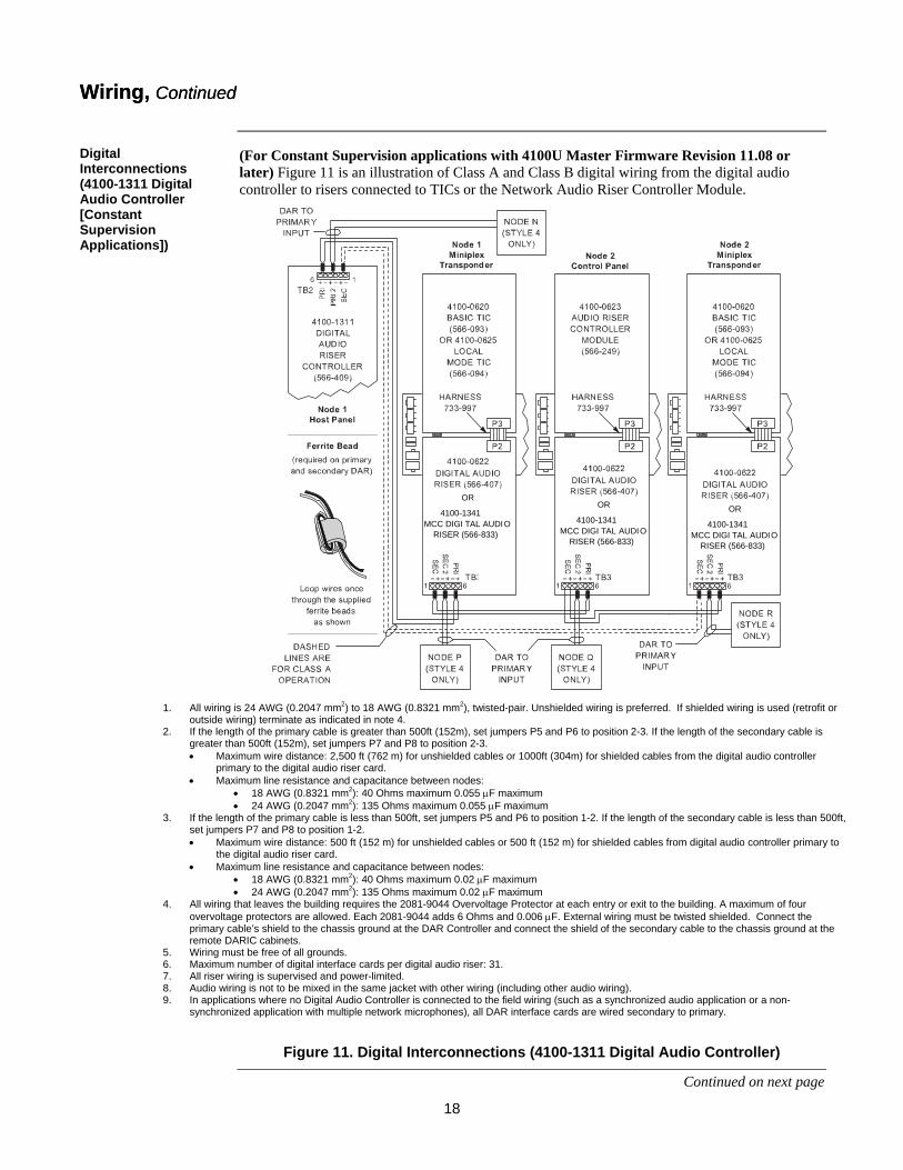
(For Constant Supervision applications with 4100U Master Firmware Revision 11.08 or later) Figure 11 is an illustration of Class A and Class B digital wiring from the digital audio controller to risers connected to TICs or the Network Audio Riser Controller Module. FigureTag FD4-844-02
OR
4100-1341MCC DIGI TAL AUDIO RISER (566-833)
OR
4100-1341MCC DIGI TAL AUDIO RISER (566-833)
OR
4100-1341MCC DIGI TAL AUDIO RISER (566-833)
Figure 11. Digital Interconnections (4100-1311 Digital Audio Controller)
Continued on next page
Wiring, Continued Wiring, Continued
Digital Interconnections (4100-1311 Digital Audio Controller [Constant Supervision Applications])
1. All wiring is 24 AWG (0.2047 mm2) to 18 AWG (0.8321 mm2), twisted-pair. Unshielded wiring is preferred. If shielded wiring is used (retrofit or outside wiring) terminate as indicated in note 4.
2. If the length of the primary cable is greater than 500ft (152m), set jumpers P5 and P6 to position 2-3. If the length of the secondary cable is greater than 500ft (152m), set jumpers P7 and P8 to position 2-3. • Maximum wire distance: 2,500 ft (762 m) for unshielded cables or 1000ft (304m) for shielded cables from the digital audio controller
primary to the digital audio riser card. • Maximum line resistance and capacitance between nodes:
• 18 AWG (0.8321 mm2): 40 Ohms maximum 0.055 μF maximum • 24 AWG (0.2047 mm2): 135 Ohms maximum 0.055 μF maximum
3. If the length of the primary cable is less than 500ft, set jumpers P5 and P6 to position 1-2. If the length of the secondary cable is less than 500ft, set jumpers P7 and P8 to position 1-2. • Maximum wire distance: 500 ft (152 m) for unshielded cables or 500 ft (152 m) for shielded cables from digital audio controller primary to
the digital audio riser card. • Maximum line resistance and capacitance between nodes:
• 18 AWG (0.8321 mm2): 40 Ohms maximum 0.02 μF maximum • 24 AWG (0.2047 mm2): 135 Ohms maximum 0.02 μF maximum
4. All wiring that leaves the building requires the 2081-9044 Overvoltage Protector at each entry or exit to the building. A maximum of four overvoltage protectors are allowed. Each 2081-9044 adds 6 Ohms and 0.006 μF. External wiring must be twisted shielded. Connect the primary cable’s shield to the chassis ground at the DAR Controller and connect the shield of the secondary cable to the chassis ground at the remote DARIC cabinets.
5. Wiring must be free of all grounds. 6. Maximum number of digital interface cards per digital audio riser: 31. 7. All riser wiring is supervised and power-limited. 8. Audio wiring is not to be mixed in the same jacket with other wiring (including other audio wiring). 9. In applications where no Digital Audio Controller is connected to the field wiring (such as a synchronized audio application or a non-
synchronized application with multiple network microphones), all DAR interface cards are wired secondary to primary.
19
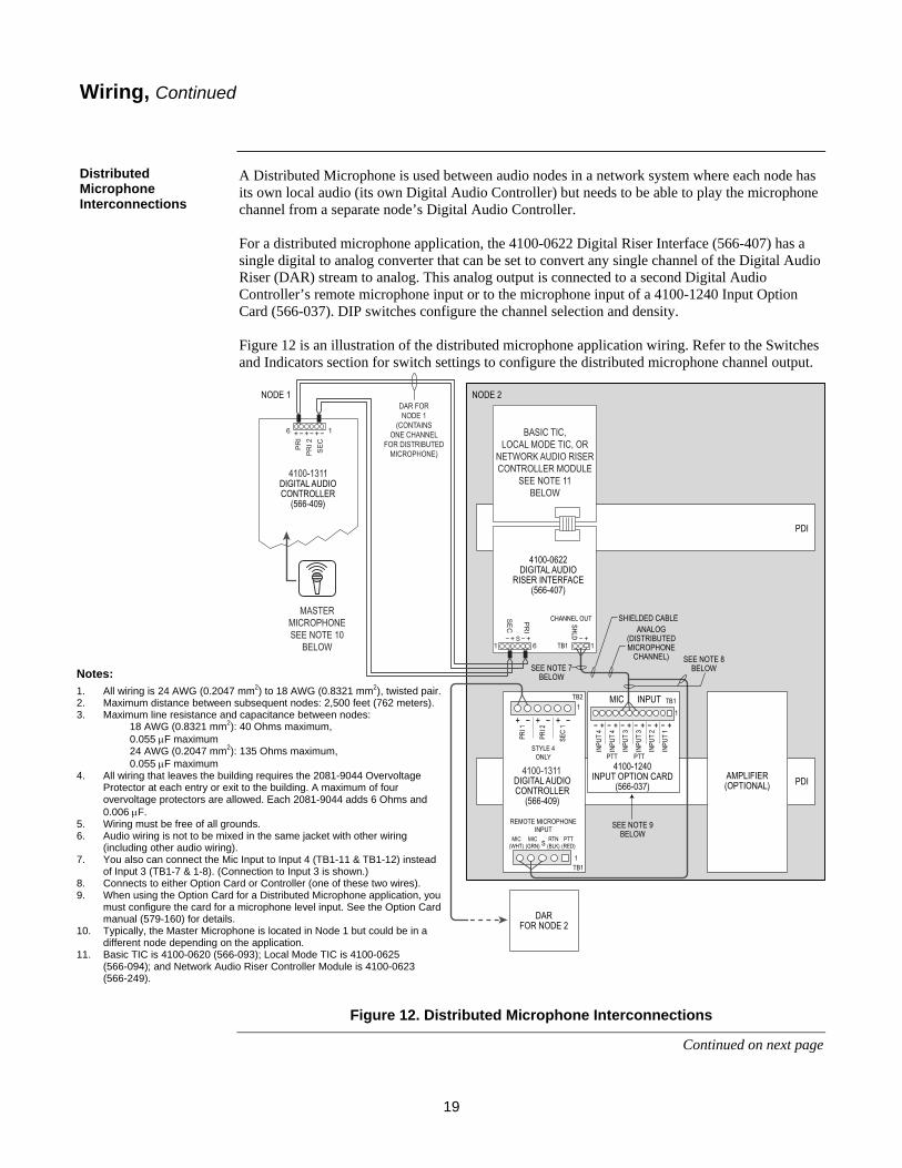
A Distributed Microphone is used between audio nodes in a network system where each node has its own local audio (its own Digital Audio Controller) but needs to be able to play the microphone channel from a separate node’s Digital Audio Controller. For a distributed microphone application, the 4100-0622 Digital Riser Interface (566-407) has a single digital to analog converter that can be set to convert any single channel of the Digital Audio Riser (DAR) stream to analog. This analog output is connected to a second Digital Audio Controller’s remote microphone input or to the microphone input of a 4100-1240 Input Option Card (566-037). DIP switches configure the channel selection and density. Figure 12 is an illustration of the distributed microphone application wiring. Refer to the Switches and Indicators section for switch settings to configure the distributed microphone channel output.
Figure 12. Distributed Microphone Interconnections
Continued on next page
Wiring, Continued
Distributed Microphone Interconnections
Notes: 1. All wiring is 24 AWG (0.2047 mm2) to 18 AWG (0.8321 mm2), twisted pair. 2. Maximum distance between subsequent nodes: 2,500 feet (762 meters). 3. Maximum line resistance and capacitance between nodes:
18 AWG (0.8321 mm2): 40 Ohms maximum, 0.055 μF maximum 24 AWG (0.2047 mm2): 135 Ohms maximum, 0.055 μF maximum
4. All wiring that leaves the building requires the 2081-9044 Overvoltage Protector at each entry or exit to the building. A maximum of four overvoltage protectors are allowed. Each 2081-9044 adds 6 Ohms and 0.006 μF.
5. Wiring must be free of all grounds. 6. Audio wiring is not to be mixed in the same jacket with other wiring
(including other audio wiring). 7. You also can connect the Mic Input to Input 4 (TB1-11 & TB1-12) instead
of Input 3 (TB1-7 & 1-8). (Connection to Input 3 is shown.) 8. Connects to either Option Card or Controller (one of these two wires). 9. When using the Option Card for a Distributed Microphone application, you
must configure the card for a microphone level input. See the Option Card manual (579-160) for details.
10. Typically, the Master Microphone is located in Node 1 but could be in a different node depending on the application.
11. Basic TIC is 4100-0620 (566-093); Local Mode TIC is 4100-0625 (566-094); and Network Audio Riser Controller Module is 4100-0623 (566-249).

20
A distributed line level signal is used between audio nodes in a Multiple Digital Command Centre (MCC) network system where nodes have local analog audio but need to be able to play the microphone, the tones, and the messages from a separate node’s Digital Audio Controller.
For this MCC application, the 4100-1341 Digital Riser Interface (566-833) has a single digital to analog converter that can be set to convert any single channel of the Digital Audio Riser (DAR) stream to line level analog. This analog output is connected to an Analog Audio Controller’s input option cards (4100-1240, 566-037) line level input. DIP switches configure the channel selection and density.
Figure 13 is an illustration of this MCC application wiring. Refer to the Switches and Indicators section for switch settings to configure the MCC DARICs channel output.
4100U ANALOG AUDIO NETWORK NODE DETAIL
NETWORK AUDIO RISER CONTROLLER MODULE
4100-1341MCC DIGITAL AUDIO RISER INTERFACE (566-833)
4100-1210ANALOG AUDIO CONTROLLER (566-218)
SHIELDED CABLE
MCC ANALOG OUTPUT
SEE NOTE 7
AMPLIFIER(OPTIONAL)
PDI
PDI 4100-1240INPUT OPTION CARD (566-037)
14 00U PC U
014 D 0 i atig uA l oidoC ortn 0014 rell 31- 11
eN owt rkCIT
&D A IR C
4 -001 260 2
14 N 02 e wt kro on ed tiw h4 U001 D i tig a A l udi V o CC
014 0 UPC U
14 D 00 i tig a A l u oidCo rtn o ell 14 r 1-00 113
14 20 N e wt ro k on ed w ith014 0U Digi duA lat i CV o C
BackupECS command center #2
ECS command center #1
eN owt rkCIT
&D A IR C
4 -001 260 2
DAR
This connection is forClass A Operation
Figure 13. Multiple Digital Command Center (4100U FACP shown)
Wiring, Continued
Notes: 1. All wiring is 24 AWG (0.2047 mm2) to 18 AWG (0.8321 mm2), twisted pair. 2. Maximum distance between subsequent nodes: 2,500 feet (762 meters). 3. Maximum line resistance and capacitance between nodes:
18 AWG (0.8321 mm2): 40 Ohms maximum, 0.055 μF maximum 24 AWG (0.2047 mm2): 135 Ohms maximum, 0.055 μF maximum
4. All wiring that leaves the building requires the 2081-9044 Overvoltage Protector at each entry or exit to the building. A maximum of four overvoltage protectors are allowed. Each 2081-9044 adds 6 Ohms and 0.006 μF.
5. Wiring must be free of all grounds. 6. Audio wiring is not to be mixed in the same jacket with other wiring (including other audio wiring). 7. When using the Option Card for a MCC, you must configure the card for a line level input. See the Option Card manual (579-160) for details. 8. Typically, the Master Microphone is located in Node 1 but could be in a different node depending on the application.
Multiple Digital Command Center Interconnections

21
This section describes configuration settings for the 4100-0622 Digital Audio Riser (DAR) Module (566-407) and the 4100-1341 MCC Digital Audio Riser Module (566-833).
Figure 14 shows the important component locations on the 4100-0622 Digital Audio Riser (DAR) Module.
SEC 1
TB3TB2
1
P2
1
TB1
21
SEC 2DAR CHANNEL OUT NAA IN
NAA OUT
NAAVOLUME
R4
SW1
LED1
LED2
LED3LED4
DAR GROUND FAULTSEARCH ACTIVE
PDI RECEIVEENABLE
PRIMARY RECEIVE
SECONDARY RECEIVE
DIGITALRISER
ON-ENABLENAA
1234
SW2LSBMSB
1234
LINE25V
70V
SHLDPRI 1
Figure 14. Digital Audio Riser Module
Table 8 lists specifications for the Digital Audio Riser Module.
Table 8. Digital Audio Riser Module (4100-0622, -1341) Specifications
Electrical Specifications
Input voltage 19-33 VDC
Input Current (Supervision
or Alarm)
With no secondary wiring: 70 mA maximum
Add 5 mA for each secondary in use
Continued on next page
Digital Audio Riser Module (566-407, -833)
Overview
Locations on the Digital Audio Riser Module
Digital Audio Riser Module Specifications
P2. Supervision Type Setting
SW1. PDI Drive Selection
SW2. Channel Out Selector
P4. NAA Input Level
R4. NAA Volume Adjustment See CAUTION on page 19
TB3. DAR Connector
TB1. Channel Out Connector
TB2. NAA In Connector
P1. Audio Riser Module Connector
LED1. DAR Ground Fault Indicator LED2. DAR
Receive on PDI Indicator
LED3. DAR Receive on Primary Indicator
LED4. DAR Receive on Secondary Indicator

22
DIP Switches Two 4-position switches (SW1 & SW2) allow for configuration of the D to A channel, DAR density, and module outputs for the 4100-0622, -1341 Digital Audio Riser Module. See Table 9.
Table 9. Switch Positions for the 4100-0622, -1341 Digital Audio Riser Module
CAUTION:
1. All four positions of Switch 1 are set to OFF at the factory to avoid module output damage. Positions 3 & 4 are only ON for Digital Systems. For Analog Systems, Positions 3 & 4 MUST REMAIN OFF to avoid DAR damage.
2. If the 4100-0622 DAR Module is installed in a bay where PDI Channel 2 is driven by a 4100-1210 Analog Audio Controller or a 4100-1265 Degraded Fail-Safe Mode Microphone Preamp, Switch Positions 1 & 2 MUST BE OFF to avoid damaging the NAA output.
Continued on next page
Digital Audio Riser Module, Continued
Switches and Indicators
SW1 (See Caution below)
Position Function State
*1 & 2 NAA
Output Enable
ON = Enable; OFF = Disable
**3 & 4 Digital
PDI Drive
ON = Enable; OFF = Disable
*ON selection disallows use of this module in the same bay as a 4100-1265 Degraded Fail-Safe Mode Microphone Preamp (566-510) or a 4100-1210 Analog Audio Controller (566-218).
**Disable the Digital PDI Drive for an analog audio system, in a distributed microphone or distributed line level application where the head-end audio never is used by the local panel.
1 = ON = CLOSED 0 = OFF = OPEN SW2
Position Channel Out
DAR Density *4 3 2 1
OFF OFF OFF OFF 1 8 ksps OFF OFF OFF ON 2 OFF OFF ON OFF 3 OFF OFF ON ON 4 OFF ON OFF OFF 5 OFF ON OFF ON 6 OFF ON ON OFF 7 OFF ON ON ON 8 ON OFF OFF OFF 1
16 ksps ON OFF OFF ON 2 ON OFF ON OFF 3 ON OFF ON ON 4
*Switch SW2-4 selects DAR density.

23
• Jumpers:
Two jumpers allow for configuration of the 4100-0622, -1341 Digital Audio Riser Module (566-407, -833 respectively) as shown in Table 10.
Table 10. Jumper Positions for the 4100-0622, -1341 Digital Audio Riser Module
P4: Analog Audio input level (for Non-Alarm Audio [NAA] Application) Position Audio Input Level
1-2 70.7 Vrms 3-4 25 Vrms 5-6 Line level (1-2V peak to peak)
P2: Supervision Type Position Function
1-2 Silence supervision* 2-3 Constant supervision
• Potentiometer R4:
Potentiometer R4 on the 4100-0622, -1341 Module allows for volume adjustment of the Non-Alarm Audio (NAA). It has a range from zero (volume can be completed silenced) to full scale. Initial factory setting is approximately one-half of full scale. Adjust the NAA volume so that it never produces overly high output that overdrives the amplifiers. To adjust the output, set the customer equipment so that its output is at its maximum normal operating level. Then adjust the riser module’s trim pot (R4 in Figure 12) so that the output of the amplifier is not distorted (as heard at the building speakers). You may then set the output of the customer equipment to a comfortable listening level LEDs:
• LEDs: LEDs indicate routing status or mode of the 4100-0622, -1341 Module as well as the ground fault search status. See Table 11.
Table 11. LED Functions for the 4100-0622, -1341 Digital Audio Riser Module
LED Color Function LED1 Yellow DAR Ground fault search active LED2 Green DAR receive on PDI LED3 Green DAR receive on primary LED4 Green DAR receive on secondary LED5 Yellow DAR Listen (On = DAR receive trouble)
The following information interprets the LEDs with respect to module mode. Note that LED2 usually indicates the mode of the PDI transceiver rather than the DAR source. • If either LED3 or LED4 is illuminated, then that input is the receive input to the module. • If the LED2 is illuminated while either LED3 or LED4 is illuminated, then the PDI drive is
disabled (the transceiver is actually in the receive mode but the input is ignored). If LED2 is illuminated while LED3 or LED4 is not illuminated, then the PDI is the DAR source for the module.
• A flashing LED3 indicates that the input is the supervised Style 7 return to the module (causes a trouble without input).
Digital Audio Riser Module, Continued
Switches and Indicators
*When the Supervision Type jumper is set to “Silence Supervision,” the additional routing options offered by this module are not available except for allowing backward compatibility with the 566-033 version of the Digital Audio Controller. Ensure that you set this jumper to “Silence Supervision” if this module is used in a system with the 566-033 version of the Digital Audio Controller or the 566-243 version of the Digital Audio Riser Interface Card.

24
This section describes the Non-Alarm Audio (NAA) Interface using a circuit on the 4100-0622 Digital Audio Riser (DAR) Module (566-407) or the 4100-1341 MCC Digital Audio Riser module (566-833). This function provides a way to interface a non-alarm audio source to Channel 2 of the Power Distribution Interface (PDI). If you use this module as a NAA interface only (analog system only), then you would use it without a TIC or 4100-0623 Audio Riser Controller Module (566-249). IMPORTANT: DO NOT install a 4100-0622, -1341 Digital Audio Riser Module using
the NAA interface IN THE SAME BAY with an Analog Audio Controller Module (or any module that would control Channel 2 of the PDI). Both modules would try unsuccessfully to control the PDI’s Channel 2.
If the modules must co-exist in the same box, then they must reside in separate bays, and have an audio harness connecting them without Channel 2 connections being made. The connecting audio harness may be a modified harness (734-167) available from the factory or a standard audio harness (734-052) that you modify as shown in Figure 15. Figure 15 shows two wires on the left that are cut close to the connector and discarded. The two cut wires were formerly connected to Pins 3 & 6 of the PDI audio connector.
Figure 15. Modified Standard Audio Harness for Specific NAA Application
Continued on next page
Non-Alarm Audio (NAA) Interface
Overview
LOCKING TAB
CUT THESE TWO WIRES

25
Refer to Figure16 to wire for the NAA Interface application
ID
PTB3
TO CUSTOMER-SUPPLIED EQUIPMENT
4100-0622DIGITALAUDIORISER
INTERFACE
4100-0623NETWORK
AUDIO RISERCONTROLLER
MODULE
DAR NAA INCHANNELOUT
TB1 TB2
OR THE 4100-1341 MCCDIGITAL AUDIO RISER INTERFACE
Figure 16. Wiring for the Non-Alarm Audio (NAA) Interface Application
Non-Alarm Audio (NAA) Interface, Continued
NAA Wiring

26
This section applies only to the field replacement of the Digital Audio Riser (DAR) Module (566-243) with the later version of this module (566-407).
The following configuration and wiring information applies when replacing the 566-243 module with the 566-407 module.
Table 12. Digital Audio Riser Module (566-243) Configuration & Wiring
Configuration (Jumpers, Switches, and Potentiometer)
Constant Supervision Jumper (P2) Position 1-2 to silence supervision
NAA Input Level (P4) Any position (not used)
NAA & PDI Outputs (SW1) Positions 1 & 2 OFF (Disables NAA Outputs)
Positions 3 & 4 ON (Enables PDI Outputs)
D to A channel & DAR density (SW2) Any position (not used)
NAA Volume (Potentiometer R4) Any position (not used)
Wiring
NAA Input (TB2) Not used
Channel Output (TB1) Not used
DAR Wiring (TB3) Wire to primary and secondary (SEC1) like 566-243. Do not use SEC2. Refer to Figure 9 for details.
Field Replacement of the Digital Audio Riser Module (566-243)
Overview
Configuration and Wiring of the Digital Audio Riser Module

27
A Digital Audio Riser Termination Plug (734-183) is provided with every Digital Audio Controller or Digital Audio Riser Module. You must use this termination plug to properly terminate the Digital Audio Signal on the PDI.
To properly terminate the Digital Audio Signal on the PDI, you must install the termination plug into P7 of the Node’s last bay that has Digital Audio. The Digital Audio Controller should be the first item and the Digital Audio Termination Plug the last item in the Digital Audio PDI Bay-to-Bay wiring. See Figure 17:
Figure 17. Installing a Digital Audio PDI Termination Plug
Digital Audio PDI Termination Plug
Overview
Installing a Digital Audio PDI Termination Plug
Place the Digital Audio PDI Termination Plug into P7 of the Node’s last bay with Digital Audio.

574-844 Rev. P