audio/video control receiver rx-1024vbkresources.jvc.com/resources/00/00/96/lvt0018-001a.pdf ·...
TRANSCRIPT

For Customer Use:Enter below the Model No. and Serial No. which are located either on the rear, bottom or side of the cabinet. Retain this information for future reference.
Model No.
Serial No.
LVT0018-001A[J]
INSTRUCTIONS
RX-1024VBKAUDIO/ VIDEO CONTROL RECEIVER
– +
RX-1024V AUDIO/VIDEO CONTROL RECEIVER
POWER
VIDEO
STANDBY
SPEAKERS
1 2PHONES
DOLBY SURROUND
DSP MODE
BALANCE/SURROUNDADJUST
SEA MODE
SEA ADJUST SETTING
MULTI JOG
MASTER VOLUME
SOURCE SELECTOR
S-VIDEO VIDEO AUDIOL R
DIGITAL INPUT FM/AM TUNING TUNER PRESET
TUNER/SEA MEMORY FM MODE
DVD
TV SOUND/DBS PHONO
TAPE/MDVCR 1
VCR 2 FM
AMVIDEO
CD
SOUND SELECT
INPUT ATT.
LOUDNESS ONE TOUCH OPERATION
SOURCE NAME
COMPULINKRemote
D I G I T A L
D I G I T A L
TV/CATV/DBS VCR 1
POWER
VCR 1 VCR 2 VIDEO
CD TAPE/MD PHONO TV/DBS
AM
MODE
SURROUND CNTR TONE CNTR– +
DIGITAL/ANALOG
INPUT
CHANNEL– +
VOLUME– +
DISC
MUTE
+10100+
10
FM
1
SLEEP
POWER POWER
AUDIO
2 3
TEST REAR · L
AUDIO/TV/VCR
CATV
DBS
REAR · R
– +
4 5 6
EFFECT
SEA MODE
RETURN FM MODE/MUTE
– +
SUBWOOFER– +
8
0
9
ENTER
MENU
MENU
SET EXIT
VCR1
/REW PLAY
TAPE
ON SCREEN CONTROL
CONTROL
LIGHT
FF/
DOWN TUNING UP
TV/VIDEO
REC
STOP PAUSE
RM-SR1024U REMOTE CONTROL
SOUND
DVD
7/P
Cover.RX-1024V[J]/1.PM5 98.5.12, 0:14 PM1
G-1
Warnings, Cautions and Others
Caution –– POWER switch!Disconnect the mains plug to shut the power off completely. ThePOWER switch in any position does not disconnect the mains line.The power can be remote controlled.
CAUTION: TO REDUCE THE RISK OF ELECTRIC SHOCK. DO NOT REMOVE COVER (OR BACK) NO USER SERVICEABLE PARTS INSIDE. REFER SERVICING TO QUALIFIED SERVICE PERSONNEL.
RISK OF ELECTRIC SHOCKDO NOT OPEN
The lightning flash with arrowhead symbol, within an equilateral triangle is intended to alert the user to the presence of uninsulated "dangerous voltage" within the product's enclosure that may be of sufficient magnitude to constitute a risk of electric shock to persons.
The exclamation point within an equilateral triangle is intended to alert the user to the presence of important operating and maintenance (servicing) instructions in the literature accompanying the appliance.
CAUTION
WARNING: TO REDUCE THE RISK OF FIRE OR ELECTRIC SHOCK, DO NOT EXPOSE THIS APPLIANCE TO RAIN OR MOISTURE.
CAUTIONTo reduce the risk of electrical shocks, fire, etc.:1. Do not remove screws, covers or cabinet.2. Do not expose this appliance to rain or moisture.
Caution –– SPEAKER LOAD SELECTOR switch!Match the position of SPEAKER LOAD SELECTOR switch on theback panel to the impedance of the speaker connected, to protectfrom overheating.
Warranty.RX-1024V[J]/1.PM5 98.5.12, 0:45 PM1

G-2
To get the best DSP (Digital Signal Processor) effect in your listening room, note the speakersettings you have set on the table below for future reference (even though the receivermemorizes the settings until you change them).
For actual setting procedures, see pages 19 to 21.
Speakers Setting
Front Speakers LARGE SMALL
Center Speaker LARGE SMALL NONE
Rear Speaker LARGE SMALL NONE
Center Delay Set to [ msec] (Select from 0 to 5 msec)
Rear Delay Set to [ msec] (Select from 0 to 15 msec)
Crossover Frequency 80 Hz 100 Hz 120 Hz
LFE Attenuator 0 dB 10 dB
Dynamic Range Compression OFF MID MAX
Note:If the power cord is unpluggedor a power failure occurs, allpreset settings will be erased ina few days.
Warranty.RX-1024V[J]/1.PM5 98.5.12, 0:45 PM2

1
Table of Contents
Parts Identification...................................................................................... 3
Getting Started........................................................................................... 4Before Installation................................................................................................................................................................... 4
Checking the Supplied Accessories ........................................................................................................................................ 4Connecting the FM and AM Antennas ................................................................................................................................... 5
Connecting the Speakers ......................................................................................................................................................... 6
Connecting Audio/Video Components ................................................................................................................................... 8Connecting the Power Cord .................................................................................................................................................. 12
Putting Batteries in the Remote Control ............................................................................................................................... 12
Basic Operations ....................................................................................... 13Turning the Power On and Off .............................................................................................................................................. 13
Selecting the Source to Play ................................................................................................................................................. 13Adjusting the Volume............................................................................................................................................................ 14
Selecting the Front Speakers ................................................................................................................................................. 15
Muting the Sound.................................................................................................................................................................. 15Using the Sleep Timer ........................................................................................................................................................... 15
Attenuating the Input Signal ................................................................................................................................................. 16
Adjusting the Subwoofer Output Level ................................................................................................................................ 16Recording a Source ............................................................................................................................................................... 16
Basic Settings........................................................................................... 17Changing the Source Name .................................................................................................................................................. 17
Selecting the Input Mode ...................................................................................................................................................... 17Adjusting the Front Speaker Output Balance ....................................................................................................................... 18
Setting the Subwoofer Information ....................................................................................................................................... 18
Listening at Low Volume (Loudness) ................................................................................................................................... 18Digital Input (DIGITAL IN) Terminal Setting...................................................................................................................... 19
Setting the Speakers for the DSP Modes .............................................................................................................................. 19
One Touch Operation .................................................................................. 22About the One Touch Operation ........................................................................................................................................... 22
Using the One Touch Operation............................................................................................................................................ 22
Receiving Radio Broadcasts ........................................................................ 23Tuning in Stations Manually ................................................................................................................................................. 23Using Preset Tuning .............................................................................................................................................................. 23
Selecting the FM Reception Mode ....................................................................................................................................... 24
Assigning Names to Preset Stations ..................................................................................................................................... 25
Using the SEA Modes ................................................................................ 26Selecting Your Favorite SEA Mode ...................................................................................................................................... 26
Creating Your Own SEA Mode............................................................................................................................................. 27
EN01-12.RX-1024V[J]/1.PM5 98.5.12, 0:16 PM1
2
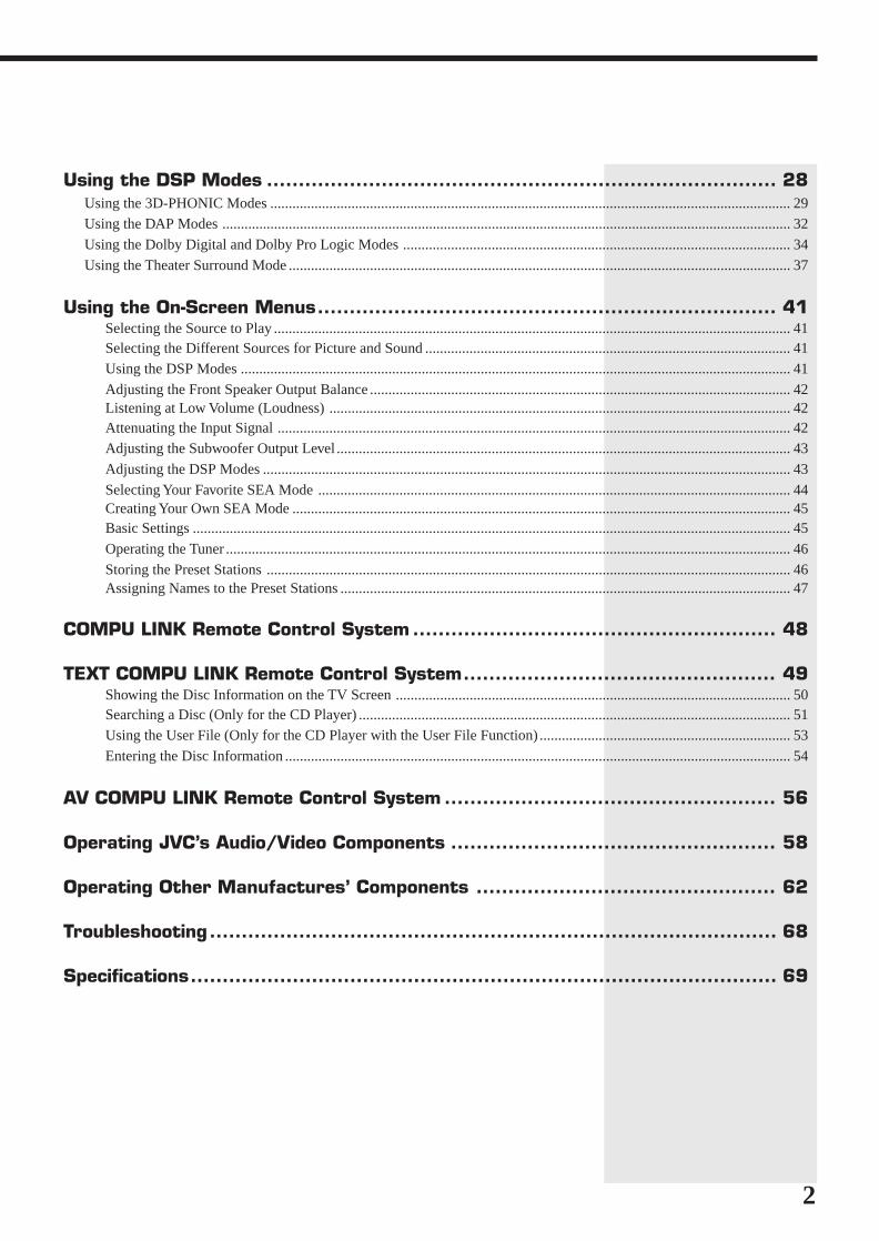
Using the DSP Modes ................................................................................ 28Using the 3D-PHONIC Modes ............................................................................................................................................. 29Using the DAP Modes .......................................................................................................................................................... 32
Using the Dolby Digital and Dolby Pro Logic Modes ......................................................................................................... 34
Using the Theater Surround Mode ........................................................................................................................................ 37
Using the On-Screen Menus........................................................................ 41Selecting the Source to Play ............................................................................................................................................ 41Selecting the Different Sources for Picture and Sound ................................................................................................... 41Using the DSP Modes ..................................................................................................................................................... 41
Adjusting the Front Speaker Output Balance .................................................................................................................. 42Listening at Low Volume (Loudness) ............................................................................................................................. 42Attenuating the Input Signal ........................................................................................................................................... 42Adjusting the Subwoofer Output Level ........................................................................................................................... 43
Adjusting the DSP Modes ............................................................................................................................................... 43
Selecting Your Favorite SEA Mode ................................................................................................................................ 44Creating Your Own SEA Mode ....................................................................................................................................... 45Basic Settings .................................................................................................................................................................. 45
Operating the Tuner ......................................................................................................................................................... 46
Storing the Preset Stations .............................................................................................................................................. 46Assigning Names to the Preset Stations .......................................................................................................................... 47
COMPU LINK Remote Control System ......................................................... 48
TEXT COMPU LINK Remote Control System................................................. 49Showing the Disc Information on the TV Screen ........................................................................................................... 50Searching a Disc (Only for the CD Player) ..................................................................................................................... 51Using the User File (Only for the CD Player with the User File Function) .................................................................... 53
Entering the Disc Information ......................................................................................................................................... 54
AV COMPU LINK Remote Control System .................................................... 56
Operating JVC’s Audio/Video Components ................................................... 58
Operating Other Manufactures’ Components ............................................... 62
Troubleshooting......................................................................................... 68
Specifications............................................................................................ 69
EN01-12.RX-1024V[J]/1.PM5 98.5.12, 0:16 PM2

3
TV/CATV/DBS VCR 1
POWER
VCR 1 VCR 2 VIDEO
CD TAPE/MD PHONO TV/DBS
AM
MODE
SURROUND CNTR TONE CNTR– +
DIGITAL/ANALOG
INPUT
CHANNEL– +
VOLUME– +
DISC
MUTE
+10100+
10
FM
1
SLEEP
POWER POWER
AUDIO
2 3
TEST REAR · L
AUDIO/TV/VCR
CATV
DBS
REAR · R
– +
4 5 6
EFFECT
SEA MODE
RETURN FM MODE/MUTE
– +
SUBWOOFER– +
7/P 8
0
9
ENTER
MENU
MENU
SET EXIT
VCR1
/REW PLAY
TAPE
ON SCREEN CONTROL
CONTROL
LIGHT
FF/
DOWN TUNING UP
TV/VIDEO
REC
STOP PAUSE
RM-SR1024U REMOTE CONTROL
DVD
SOUND
Parts IdentificationBecome familiar with the buttons and controls on the receiver before use.
Refer to the pages in parentheses for details.
Front Panel1 POWER button and STANDBY lamp (13)2 Remote sensor (12)3 DOLBY SURROUND button and lamp (36)4 SEA MODE button (26) *5 DIGITAL INPUT button (17)6 FM/AM TUNING button (23) *7 FM MODE button (24)8 Display (13)9 Source lamps (13)0 MASTER VOLUME control (14)- PHONES jack (15)= SPEAKERS 1/2 buttons and lamps (15)~ DSP MODE button (29) *! BALANCE/SURROUND ADJUST button
(18, 30) *@ SEA ADJUST button (27) *# SETTING button (18) *$ TUNER/SEA MEMORY button (23, 25, 27)% SOUND SELECT/INPUT ATT. button
(14, 16)^ LOUDNESS/SOURCE NAME button
(17, 18)& ONE TOUCH OPERATION button and
lamp (22)* TUNER PRESET button (24) *( MULTI JOG control
What this control actually doesdepends on which function you aretrying to adjust. Before using thiscontrol, select the function bypressing one of the buttons markedwith *.
) SOURCE SELECTOR control (13)_ VIDEO input jacks (10)
Remote Control+ TV/CATV/DBS POWER and VCR1
POWER buttons (60, 61)¡ Source selecting buttons (14)™ SURROUND MODE button (31)£ DIGITAL/ANALOG INPUT button (17)¢ SOUND button (26, 31, 58)∞ DISC button (59)§ CHANNEL buttons (+/–) (60, 62)¶ MUTE button (15)• VCR1 CONTROL button (60, 64)ª LIGHT buttonº AUDIO POWER button (13)– SLEEP button (15)≠ 10 keys for selecting preset channel (24)
10 keys for adjusting sound (26, 31)10 keys for operating audio/videocomponents (58, 62)
Ÿ Remote control mode selector (AUDIO/TV/VCR, CATV, DBS) (13, 58, 62)To operate an audio system, TV,and VCR, set this selector to“AUDIO/TV/VCR.”To operate a CATV converter, setthis selector to “CATV.”To operate a DBS tuner, set thisselector to “DBS.”
⁄ VOLUME buttons (+/–) (14)¤ MENU operating buttons (SET, EXIT, %,
fi, @, #) (41)‹ TAPE CONTROL button (59)› Operating buttons for audio/video
components (58, 62)
1 2 3 4 5 6 9 0
– +
RX-1024V AUDIO/VIDEO CONTROL RECEIVER
POWER
VIDEO
STANDBY
SPEAKERS
1 2PHONES
DOLBY SURROUND
DSP MODE
BALANCE/SURROUNDADJUST
SEA MODE
SEA ADJUST SETTING
MULTI JOG
MASTER VOLUME
SOURCE SELECTOR
S-VIDEO VIDEO AUDIOL R
DIGITAL INPUT FM/AM TUNING TUNER PRESET
TUNER/SEA MEMORY FM MODE
DVD
TV SOUND/DBS PHONO
TAPE/MDVCR 1
VCR 2 FM
AMVIDEO
CD
SOUND SELECT
INPUT ATT.
LOUDNESS ONE TOUCH OPERATION
SOURCE NAME
COMPULINKRemote
D I G I T A L
7
- = @ $ ^ * ( ) _~ ! # % &
8
+
¡
™
£
¢
∞
§
¶
•
ª
º
–
≠
Ÿ
⁄
›
‹
¤
When using the remote controlin the dark
Press LIGHT (ª).The buttons on the remote control arebacklit while you are using the remotecontrol.If you do not press any button forabout 5 seconds, backlight will turnoff.
EN01-12.RX-1024V[J]/1.PM5 98.5.12, 0:16 PM3

4
Getting StartedThis section explains how to connect audio/video components and speakers to the receiver, and how toconnect the power supply.
Before Installation
General• Be sure your hands are dry.• Turn the power off to all components.• Read the manuals supplied with the components you are going to connect.
Locations• Install the receiver in a location that is level and protected from moisture.• The temperature around the receiver must be between 23˚ and 95˚ F (–5˚ and 35˚ C).• Make sure there is good ventilation around the receiver. Poor ventilation could cause
overheating and damage the receiver.
Handling the receiver• Do not insert any metal object into the receiver.• Do not disassemble the receiver or remove screws, covers, or cabinet.• Do not expose the receiver to rain or moisture.
Checking the Supplied Accessories
Check to be sure you have all of the following items, which are supplied with thereceiver.The number in the parentheses indicates quantity of the pieces supplied.
• Remote Control (1)
• Batteries (2)
• AM Loop Antenna (1)
• FM Antenna (1)
If anything is missing, contact your dealer immediately.
EN01-12.RX-1024V[J]/1.PM5 98.5.12, 0:16 PM4

5
AMEXT
AMLOOP
GND
FM75
FMGND
ANTENNA
2 31
4
3 421
Connecting the FM and AM Antennas
FM Antenna Connections
Notes:• Make sure the antenna
conductors do not touch anyother terminals, connectingcords and power cord. Thiscould cause poor reception.
• If reception is poor, connectan outdoor single vinyl-covered wire to the AM EXTterminal. (Keep the AM loopantenna connected.)
Note:If reception is poor, connect theoutside antenna.Before attaching a 75Ω coaxialcable (the kind with a round wiregoing to an outside antenna),disconnect the supplied FM wireantenna.
7/16 in.
(10 mm)13/16 in.
(20 mm)
AM Antenna Connections
AM Loop Antenna
Turn the loop until youhave the best reception.
Snap the tabs on the loopinto the slots of the base toassemble the AM loop.
How to strip the 75Ω coaxial cable and connect it to the FMterminals1. Strip back the outside covering of the 75Ω coaxial cable to expose the braided
metallic mesh about 13/16 inches (20 mm).2. Pull the mesh back and twist it into a single connector as shown in the illustration
above.3. Strip the insulation about 7/16 inches (10 mm) back from the central wire.4. Insert the twisted mesh and the central wire to the FM terminals, as shown in the
illustration above.
Outdoor single vinyl-covered wire
AMEXT
AMLOOP
GND
FM75
FMGND
ANTENNA
2 31
Getting Started
Outside FM Antenna Wire
Extend the FM wire antenna horizontally.
FM Antenna
EN01-12.RX-1024V[J]/1.PM5 98.5.12, 0:16 PM5

6
Connecting the Speakers
You can connect the following speakers:• Two pairs of front speakers to produce normal stereo sound.• One pair of rear speakers to enjoy the surround effect.• One center speaker to produce more effective surround effect (to emphasize human
voices).• One subwoofer to enhance the bass.
IMPORTANT:After connecting the speakers listed above, set the speaker setting informationproperly to obtain the best possible performance. For details, see pages 18 and 19.
For each speaker (except for subwoofer), connect the (–) and (+) terminals on therear panel to the (–) and (+) terminals marked on the speakers. For connecting asubwoofer, see page 7.
1 Cut, twist and remove the insulation at the end of each speaker signal cable.
2 Turn the knob counterclockwise.
3 Insert the speaker signal cable.
4 Turn the knob clockwise.
Connecting the front speakersConnect the front speakers to the FRONT SPEAKERS terminals.You can connect two pairs of front speakers (one pair to the FRONT SPEAKERS 1
terminals, and another pair to the FRONT SPEAKERS 2 terminals).
RIGHT
1
RIGHT
1
1 3 4
RIGHT
1
2
CAUTION:
Use speakers with theSPEAKER IMPEDANCEindicated by the speakerterminals.
Note:To obtain the best possibleoutput power from the receiver,and to prevent the receiver frombeing overheated, the receiverhas the SPEAKER LOADSELECTOR which has to be setas follows:• Set it to the HIGH position
when the impedance of thespeakers connected is withinthe range of 8 ohms to 16ohms.
• Set it to the LOW positionwhen the impedance of thespeakers connected is withinthe range of 4 ohms to 6ohms.
• Set it to the LOW positionwhen the impedance of theany speaker connected is 6ohms or less.
Right speakerLeft speaker
SPEAKERIMPEDANCE
/ OHMS
4 ~ 68 ~ 16
+ – +–
RIGHT LEFT
1
2
1
2
SPEAKERLOAD
SELECTORLOWHIGH
FRONT SPEAKERS
SPEAKER LOAD POSITIONED LOWSPEAKER LESS
EN01-12.RX-1024V[J]/1.PM5 98.5.12, 0:16 PM6

7
Connecting the rear and center speakersConnect the rear speakers to the REAR SPEAKERS terminals and a center speaker tothe CENTER SPEAKER terminals.
Connecting the subwoofer speakerConnect the input jack of a powered subwoofer to the SUBWOOFER jack on the rearpanel, using a cable with RCA pin plugs.
To enhance your audio systemYou can use this receiver as the pre-amplifier (control amplifier) when you connectpower amplifiers to the PRE OUT jacks on the rear panel, using cables with RCA pinplugs.
Getting Started
CAUTION:
Use speakers with theSPEAKER IMPEDANCEindicated by the speakerterminals.
Note:To obtain the best possibleoutput power from the receiver,and to prevent the receiver frombeing overheated, the receiverhas the SPEAKER LOADSELECTOR which has to be setas follows:• Set it to the HIGH position
when the impedance of thespeakers connected is withinthe range of 8 ohms to 16ohms.
• Set it to the LOW positionwhen the impedance of thespeakers connected is withinthe range of 4 ohms to 6ohms.
• Set it to the LOW positionwhen the impedance of theany speaker connected is 6ohms or less.
+
–
+
–
RIGHT LEFT
CENTERSPEAKER
REARSPEAKERS
Center speaker
Left rear speaker Right rear speaker
PRE OUT
REAR
SUBWOOFER
FRONT
CENTERRIGHT RIGHT
LEFT
LEFT
Powered subwoofer
PRE OUT
REAR
SUBWOOFER
FRONT
CENTERRIGHT RIGHT
LEFT
LEFT
Power amplifier
Example: When using a stereo power amplifierfor connecting the rear speakers
Left rear speaker Right rear speaker
EN01-12.RX-1024V[J]/1.PM5 98.5.12, 0:16 PM7

8
Connecting Audio/Video Components
You can connect the following audio/video components to this receiver. Refer also to themanuals supplied with your components. If you want to connect a component not listedin the table below, refer to the manual supplied with it.
Analog connections
Audio component connections
Use the cables with RCA pin plugs (not supplied).Connect the white plug to the audio left jack, and the red plug to the audio right jack.
CAUTION:
If you connect a sound-enhancing device such as agraphic equalizer between thesource components and thisreceiver, the sound outputthrough this receiver may bedistorted.
Notes:• Any turntables incorporating
a small-output cartridge suchas an MC (moving-coil type)must be connected to thisreceiver through acommercial head amplifier orstep-up transformer. Directconnection may result ininsufficient volume.
• You can connect either acassette deck or an MDrecorder to the TAPE/MDjacks. When connecting anMD recorder to the TAPE/MDjacks, change the sourcename, which will be shown onthe display when selected asthe source, to “MD.” See page17 for details.
Audio Components Video Components• Turntable • DVD player*
• CD player* • TV• Cassette deck or MD recorder* • DBS tuner*
• VCRs
• Video camera
* You can connect these components using the methods described in “Analogconnections” (below) or in “Digital connections” (see page 11).
GNDRIGHT LEFT
TAPE/MD
IN(PLAY)
OUT(REC)
CD
PHONO
AUDIO
If your audio components have a COMPU LINK-3 or TEXT COMPULINK terminal• See also page 48 for detailed information about the connection and the COMPU
LINK-3 remote control system.• See also page 49 for detailed information about the connection and the TEXT
COMPU LINK remote control system.
Cassette deckor
MD recorder
To audio output
To audio output
To audio input
To audio input
To audio output
If an earth cable is provided for yourturntable, connect the cable to thescrew marked GND on the rear panel.
To audio output
Turntable
CD player
EN01-12.RX-1024V[J]/1.PM5 98.5.12, 0:16 PM8

9
Video component connections
Use the cables with RCA pin plugs (not supplied).Connect the white plug to the audio left jack, the red plug to the audio right jack, andthe yellow plug to the video jack.If your video components have S-video (Y/C-separation) terminals, connect them usingS-video cables (not supplied). Connecting these video components through the S-videoinput/output terminals will give you better picture playback (or recording) quality.
IMPORTANT:This receiver is equipped with both the composite video and S-video input/outputterminals for connecting video components.You do not have to connect both the composite video and S-video terminals.However, remember that the video signals from the composite video inputterminals are output only through the composite video output terminals,while the ones from the S-video input terminals are output only through theS-video output terminals.Therefore, if a recording video component and a playing video component areconnected to the receiver through the different video terminals, you cannot recordthe picture from the playing component on the recording component. In addition,if the TV and a playing video component are connected to the receiver through thedifferent video terminals, you cannot view the playback picture from the playingcomponent on the TV.
To view and record the playback picture from the video component connectedto the VCR 2 jacks, you must connect the TV and the recording videocomponent through the composite video terminals.
Getting Started
Connecting the TV and/or DBS tuner
You can connect either the TV or DBS tuner to the TV SOUND/DBS jacks.
To audio output
To composite video input
To S-video input
Connect the TV to theMONITOR OUT jack toview the playback picturefrom the other connectedvideo components.TV
TV SOUND/DBS
DBS
DBS tuner
To audio/video output
RIGHTVIDEO
VIDEO S-VIDEORIGHT LEFTAUDIO
MONITOROUT
VCR 1
IN(PLAY)
OUT(REC)
IN(PLAY)
OUT(REC)
TV SOUND/DBS
DVD
VCR 2
Notes:• When connecting the TV to
the TV SOUND/DBS jacks,DO NOT connect the TV’svideo output to these videoinput terminals.
• When connecting the DBStuner to the TV SOUND/DBSjacks, change the sourcename, which will be shown onthe display when selected asthe source, to “DBS.” Seepage 17 for details.
• To enjoy Dolby Digital with theDBS tuner as the source,connect the DBS tuner usingthe method described in“Digital connections” on page11.
EN01-12.RX-1024V[J]/1.PM5 98.5.12, 0:16 PM9

10
– +
RX-1024V AUDIO/VIDEO CONTROL RECEIVER
POWER
VIDEO
STANDBY
SPEAKERS
1 2PHONES
DOLBY SURROUND
DSP MODE
BALANCE/SURROUNDADJUST
SEA MODE
SEA ADJUST SETTING
MULTI JOG
MASTER VOLUME
SOURCE SELECTOR
S-VIDEO VIDEO AUDIOL R
DIGITAL INPUT FM/AM TUNING TUNER PRESET
TUNER/SEA MEMORY FM MODE
DVD
TV SOUND/DBS PHONO
TAPE/MDVCR 1
VCR 2 FM
AMVIDEO
CD
SOUND SELECT
INPUT ATT.
LOUDNESS ONE TOUCH OPERATION
SOURCE NAME
COMPULINKRemote
D I G I T A L
VIDEOS-VIDEO VIDEO AUDIOL R
RIGHTVIDEO
VIDEO S-VIDEORIGHT LEFTAUDIO
TV SOUND/DBS
DVD
DVD
To audio/videooutput
DVD player
Connecting VCRs RIGHTVIDEO
VIDEO S-VIDEORIGHT LEFTAUDIO
MONITOROUT
VCR 1
IN(PLAY)
OUT(REC)
IN(PLAY)
OUT(REC)
TV SOUND/DBS
DVD
VCR 2
S-VHS
VHS
S-VHS (or VHS) VCR
To audio/video output
To audio/video input
To audio/video output
To audio/video input
To audio/video output
Video camera
Note:To enjoy Dolby Digital with theDVD player as the source,connect the DVD player, usingthe method described in “Digitalconnections” on page 11.
If your video components have an AV COMPU LINK terminalSee also page 56 for detailed information about the connection and the AV COMPULINK remote control system.
VHS VCR
Connecting DVD player
EN01-12.RX-1024V[J]/1.PM5 98.5.12, 0:17 PM10

11
DVD
DIGITAL IN
DIGITAL 3 (CD)
DIGITAL 2 (DVD)
DIGITAL 1 (DBS)
PCM/DOLBY DIGITAL
DBS
Getting Started
Digital connectionsThis receiver is equipped with three DIGITAL IN terminals — one digital coaxialterminal and two digital optical terminals.To enjoy Dolby Digital, you have to connect the source components using the DIGITALIN terminals.You can connect any component to any one of the digital terminals using the digitalcoaxial cable (not supplied) or digital optical cable (not supplied).
DVD player
CD player
MD recorder
DBS tuner
When the component has a digitaloptical output terminal, connect itto the DIGITAL2 (DVD) orDIGITAL3 (CD) terminal, using thedigital optical cable (not supplied).
When the component has a digitalcoaxial output terminal, connect itto the DIGITAL1 (DBS) terminal,using the digital coaxial cable (notsupplied).
Before connecting adigital optical cable,unplug the protectiveplug.
IMPORTANT:• When connecting the DVD player or the DBS tuner using the digital terminal,
you also need to connect it to the video jack (either composite video terminalor S-video terminal) on the rear. Without connecting it to the video jack, youcan view no playback picture.
• After connecting the above components using the DIGITAL IN terminals, setthe following correctly if necessary.– Select the digital input mode correctly. For details, see “Selecting the Input
Mode” on page 17.– Set the digital input (DIGITAL IN) terminal setting correctly. For details,
see “Digital Input (DIGITAL IN) Terminal Setting” on page 19.
Notes:• When shipped from the
factory, the DIGITAL INterminals has been set for usewith the followingcomponents.– DIGITAL 1 (coaxial): For
DBS tuner– DIGITAL 2 (optical): For
DVD player– DIGITAL 3 (optical): For CD
player• When you want to operate the
CD player or MD recorderusing the COMPU LINKremote control system,connect the target componentalso as described in “Analogconnections” (see page 8).
EN01-12.RX-1024V[J]/1.PM5 98.5.12, 0:17 PM11

12
Notes:• A small amount of power is
always consumed even instandby mode. To switch offthe power completely, unplugthe power cord from the ACoutlet.
• If the power cord is unpluggedor a power failure occurs,preset settings will be erasedin a few days.
CAUTIONS:
• Do not touch the power cordwith wet hands.
• Do not pull on the power cordto unplug the cord. Whenunplugging the cord, alwaysgrasp the plug so as not todamage the cord.
Connecting the Power Cord
Before plugging the receiver into an AC outlet, make sure that all connections have beenmade.When the power cord is connected, the STANDBY lamp above the POWER buttonlights up.
Keep the power cord away from the connecting cables and antenna. The power cordmay cause noise or screen interference. We recommend that you use a coaxial cable toconnect the antenna, since it is well-shielded against interference.
Putting Batteries in the Remote Control
Before using the remote control, put two supplied batteries first. When using the remotecontrol, aim the remote control directly at the remote sensor on the receiver.
1. On the back of the remote control, remove the battery cover as illustrated.
2. Insert batteries. Make sure to observe the proper polarity: (+) to (+) and (–) to(–).
3. Replace the cover.
If the range or effectiveness of the remote control decreases, replace the batteries. Usetwo R6P (SUM-3)/AA (15F) type dry-cell batteries.
CAUTION:
Follow these precautions toavoid leaking or cracking cells:• Place batteries in the remote
control so they match thepolarity indicated: (+) to (+)and (–) to (–).
• Use the correct type ofbatteries. Batteries that looksimilar may differ in voltage.
• Always replace both batteriesat the same time.
• Do not expose batteries toheat or flame.
R6P (SUM-3)/AA (15F)
EN01-12.RX-1024V[J]/1.PM5 98.5.12, 0:17 PM12

13
Basic OperationsThe following operations are commonly used when you play any sound source.
IMPORTANT:When using the Remote Control, check to see if its remote controlmode selector is set to the correct position:To operate an audio system, TV, and VCR, set it to “AUDIO/TV/VCR.”To operate a CATV converter, set it to “CATV.”To operate a DBS tuner, set it to “DBS.”
Turning the Power On and Off
On the front panel:To turn on the power, press POWER.The STANDBY lamp goes off. The name of the current source (orstation frequency) appears on the display.• When the TV is connected to the TV SOUND/DBS jacks on the rear:
The receiver automatically turns on and select “TV SOUND” as the source about 5seconds after you turn on the TV. (If you change the source name from “TVSOUND” to “DBS,” the receiver will not turn on along with the TV. See page 17)
To turn off the power, press POWER again.The STANDBY lamp lights up.
From the remote control:To turn on the power, press AUDIO POWER.The STANDBY lamp goes off. The name of the current source (orstation frequency) appears on the display.
To turn off the power, press AUDIO POWER again.The STANDBY lamp lights up.
Selecting the Source to Play
On the front panel:Turn SOURCE SELECTOR until the source name you wantappears on the display.As you turn the selector, the source changes as follows:
The selected source lamp also lights up.
AUDIO/TV/VCR
CATV
DBS
What are the followingindicators?When you select the sourceencoded with Dolby Digital andstart playback, the followingindicators light up on the displayto show the signal being input tothis receiver. (Only the indicatorsfor the received signals light up.)
L: Left front channelR: Right front channelC: Center channelLS: Left rear channelRS: Right rear channelS: Rear channel (monaural)LFE: Subwoofer channel
S
C
DIGITAL
LS
L
LFE
RS
R
POWER
STANDBY
Note:When connecting an MDrecorder (to the TAPE/MDjacks), and a DBS tuner (to theTV SOUND/DBS jacks), changethe source name appears on thedisplay. For details, see page17.
POWER
AUDIO
POWER
STANDBY
FM
TV SOUND/DBSVIDEO
PHONOCD TAPE/MD AM DVD
VCR1VCR2
CH–
CNTR
100 1k 10k
DIGITAL
MUTE AUTOVOLUME
THEATER DRAMALIVE CLUB ACTIONDANCE CLUBHALL HEADPHONEPAVILION
PRO LOGIC TUNEDSTEREO
FR
LS
L
LEE
S
C D S P
3D-PHONC LOUDNESS
SLEEPATTRS
R
S E A
Selected source name appears
Source lamps on thefront panel
DVD
TV SOUND/DBS PHONO
TAPE/MDVCR 1
VCR 2 FM
AMVIDEO
CD
SOURCE SELECTOR
Current source name appears
100 1k 10k
VOLUME
FR
Current volume levelis shown here
Note:When you turn off the receiverwith the TV kept turned on, thereceiver will turn on soon again.To prevent this from happening,make sure that you turn off theTV before turning off thereceiver.
EN13_22.RX-1024V[J]/1.PM5 98.5.12, 0:18 PM13

14
From the remote control:Press one of the source selecting buttons directly.
DVD Selects the DVD player.VCR1 Selects the video component connected to the VCR1
jacks.VCR2 Selects the video component connected to the VCR2
jacks.VIDEO Selects the video component connected to the
VIDEO jacks.CD* Selects the CD player.TAPE/MD* Selects the cassette deck or the MD recorder.PHONO* Selects the turntable.FM* Selects an FM broadcast.AM* Selects an AM broadcast.TV/DBS • Selects TV sounds when the remote control selector is set to “AUDIO/
TV/VCR.”• Selects the DBS tuner when the remote control selector is set to “DBS.”
Selecting different sources for picture and soundYou can watch picture from a video component while listening to sound from anothercomponent.
On the front panel:1. Press SOUND SELECT briefly while viewing the picture from
a video component such as the VCR or DVD player, etc.“SOUND SELECT” appears on the display.
2. Turn SOURCE SELECTOR to select the sound (except the TVsound), while the indication of the above step is still on thedisplay.
From the remote control:Press one of the audio source selecting buttons (CD, TAPE/MD, PHONO, FM, AM),while viewing the picture from a video component such as the VCR or DVD player, etc.
Adjusting the Volume
On the front panel:To increase the volume, turn MASTER VOLUME clockwise.To decrease the volume, turn it counterclockwise.
When you turn MASTER VOLUME rapidly , the volumelevel also changes rapidly .When you turn MASTER VOLUME slowly, the volumelevel also changes slowly.
From the remote control:To increase the volume, press VOLUME +.To decrease the volume, press VOLUME –.
Note:When you press one of thesource selecting buttonsmarked above with an asterisk(*), the receiver automaticallyturns on.
Notes:• Once you have selected a
video source, pictures of theselected source is sent to theTV until you select anothervideo source.
• When you select TV sound asthe source, this function doesnot work.
SOUND SELECT
INPUT ATT.
SOURCE SELECTOR
– +
MASTER VOLUME
CAUTION:
Always set the volume to theminimum before starting anysource. If the volume is set at itshigh level, the sudden blast ofsound energy can permanentlydamage your hearing and/orruin your speakers.
Note:The volume level can beadjusted within the range of “0”(minimum) to “90” (maximum).
VCR 1 VCR 2 VIDEO
CD TAPE/MD PHONO TV/DBS
AM FM
DVD
VOLUME– +
EN13_22.RX-1024V[J]/1.PM5 98.5.12, 0:18 PM14

15
Basic Operations
Selecting the Front Speakers
On the front panel only:When you have connected two pairs of the front speakers, you canselect which to use.
Press SPEAKERS 1 or SPEAKERS 2 to select the speaker to use.Each time you press the button, the lamp on the respective button turns on and off.When the lamp on either button lights up, the respective speakers are activated.
IMPORTANT:You can activate two pairs of the front speakers at the same time only when theSPEAKER LOAD SELECTOR on the rear panel is set to “HIGH” and when nosignals are sent to the center and rear speakers. Otherwise, activating one pair ofthe speakers deactivates the other.
Listening only with headphones1. Connect a pair of headphones to the PHONES jack on the front panel.2. Press SPEAKERS 1 and/or 2 so that no lamps on the buttons are turned on.
Muting the Sound
From the remote control only:Press MUTE to mute the sound through all speakers andheadphones connected.“MUTE” appears on the display and the volume turns off (thevolume level indicator also goes off).
To restore the sound, press MUTE again so that “OFF” appears on the display.Turning MASTER VOLUME or pressing VOLUME +/– also restores the sound at theprevious volume level.
Using the Sleep Timer
Using the Sleep Timer, you can fall asleep to music and know the receiver will turn offby itself rather than play all night.
From the remote control only:Press SLEEP repeatedly.The SLEEP indicator lights up on the display, and the shut-offtime on the display changes as follows.
= SLEEP 10min. = SLEEP 20min. = SLEEP 30min. = SLEEP 40min.= SLEEP 50min. = SLEEP 60min. = SLEEP 70min. = SLEEP 80min.= SLEEP 90min. = SLEEP 00min. (Canceled) = (back to the beginning)
When the shut-off time comesThe receiver turns off automatically.
To check or change the time remaining until the shut-off timePress SLEEP once. The remaining time until the shut-off time appears in minutes.• To change the shut-off time, press SLEEP repeatedly.
To cancel the Sleep TimerPress SLEEP repeatedly until “SLEEP 00min.” appears on the display. (The SLEEPindicator goes off.)Turning off the power also cancels the Sleep Timer.
SPEAKERS
1 2
Note:If you use any of the DSPmodes other than the 3D-PHONIC modes and“HEADPHONE” with both frontspeakers activated, thespeakers connected to theFRONT SPEAKERS 2terminals are deactivated.
CAUTION:
Be sure to turn down the volumebefore connecting or putting onheadphones, as high volumecan damage both theheadphones and your hearing.
Note:You cannot shut off the soundthrough the subwoofer using theSPEAKERS 1 and 2 buttons.
MUTE
SLEEP
Note:When the TV is connected to theTV SOUND/DBS jacks on therear:The receiver will turn on soonagain after the Sleep Timer shutoff the receiver if the TV is keptturned on.To prevent this from happening,make sure that you turn off theTV before the Sleep Timer turnsoff the receiver.
EN13_22.RX-1024V[J]/1.PM5 98.5.12, 0:18 PM15

16
Attenuating the Input Signal
When the input level of the playing source through the analog terminals is too high, thesounds will be distorted. If this happens, you need to attenuate the input signal level toprevent the sound distortion.
On the front panel only:Press and hold SOUND SELECT/INPUT ATT until “INPUTATT ON” appears on the display.The ATT indicator also lights up on the display.
Each time you press and hold the button, the input attenuator modeturns on (“INPUT ATT ON”) and off (“INPUT NORMAL”).You can set input attenuator mode separately for each source.
Adjusting the Subwoofer Output Level
You can adjust the subwoofer output level if you have selected “YES” for the“SUBWOOFER” (see page 18).Once it has been adjusted, the receiver memorizes the adjustment.
On the front panel:1. Press BALANCE/SURROUND ADJUST repeatedly until
“SUBWFR LEVEL” appears on the display.The display changes to show the current setting.
2. Turn MULTI JOG to adjust the subwoofer output level (–10 dB to +10 dB), while the indication of the previous step isstill on the display.
From the remote control:1. Press SOUND.
10 keys are activated for sound adjustments.
2. Press SUBWOOFER +/– to adjust the subwoofer outputlevel (–10 dB to +10 dB).
Recording a Source
You can record any source playing through the receiver to the cassette deck or the MDrecorder connected to the TAPE/MD jacks and the VCRs connected to the VCR1 andVCR2 jacks at the same time.While recording, you can listen to the selected sound source at whatever sound levelyou like, without affecting the sound levels of the recording.
MULTI JOG
BALANCE/SURROUNDADJUST
SOUND SELECT
INPUT ATT.
Notes:• This function is available only
for the sources connectedusing the analog terminals.
• This function takes effect onlywhen the DSP mode is in use.
Note:The output volume level andSEA modes cannot affect therecording.
IMPORTANT:
When recording the digitalsource, turn off the DSP mode.
SOUND
+10100+FM MODE/
MUTE
SUBWOOFER– +
0
EN13_22.RX-1024V[J]/1.PM5 98.5.12, 0:18 PM16

17
Basic SettingsSome of the following settings are required after connecting and positioning your speakers in your listeningroom, while others will make operations easier.
IMPORTANT:When using the Remote Control, check to see if its remote controlmode selector is set to the correct position:To operate this receiver, set it to “AUDIO/TV/VCR” (except whenselecting the DBS tuner as the source).
Changing the Source Name
If you have connected an MD recorder to the TAPE/MD jacks or the DBS tuner to theTV SOUND/DBS jacks on the rear panel, change the source name shown on the displaywhen you select the MD recorder or DBS tuner as the source.
On the front panel only:1. When changing the source name from “TAPE” to “MD”:
• Turn SOURCE SELECTOR until “TAPE” appears.When changing the source name from “TV SOUND” to“DBS”:• Turn SOURCE SELECTOR until “TV SOUND”
appears.
2. Press and hold SOURCE NAME until “ASSGN.MD” or “ASSGN. DBS” appears on the display.
To change the source names to “TAPE” or “TV SOUND,” repeat the same procedureabove (in step 1, select “MD” or “DBS” then press and hold SOURCE NAME).
Selecting the Input Mode
When you have connected some components such as CD player, MD recorder, DVDplayer and the DBS tuner using digital terminals (see page 11), you need to change theinput mode for these components to the digital input.
On the front panel:1. Turn SOURCE SELECTOR until the source (CD, MD,
DBS, or DVD) for which you want to change the inputmode from analog input to digital input.
2. Press DIGITAL INPUT to change the input mode.Each time you press the button, the input mode alternatesbetween the digital input and analog input.
From the remote control:1. Press the source selecting button (CD, TAPE/MD, TV/DBS,
or DVD) for which you want to change the input mode fromanalog input to digital input.
2. Press DIGITAL/ANALOG INPUT to change the inputmode.Each time you press the button, the input mode alternatesbetween the digital input and analog input.
Note:Without changing the sourcename, you can still use theconnected components.However, there may be someinconvenience.– “TAPE” or “TV SOUND” will
appear on the display whenyou select the MD recorder orDBS tuner.
– You cannot use the digitalinput (see below) for the MDrecorder and the DBS tuner.
– You cannot use the COMPULINK remote control system(see page 48) to operate theMD recorder.
SOURCE SELECTOR
LOUDNESS
SOURCE NAME
Note:Once you have set the digitalinput for these components, it isalways used every time youselect these components as thesource.
SOURCE SELECTOR
DIGITAL INPUT
VCR 1 VCR 2 VIDEO
CD TAPE/MD PHONO TV/DBS
AM FM
DVD
DIGITAL/ANALOG
INPUT
AUDIO/TV/VCR
CATV
DBS
EN13_22.RX-1024V[J]/1.PM5 98.5.12, 0:18 PM17
18
BALANCE/SURROUNDADJUST
MULTI JOG
LOUDNESS
SOURCE NAME
SETTING
MULTI JOG
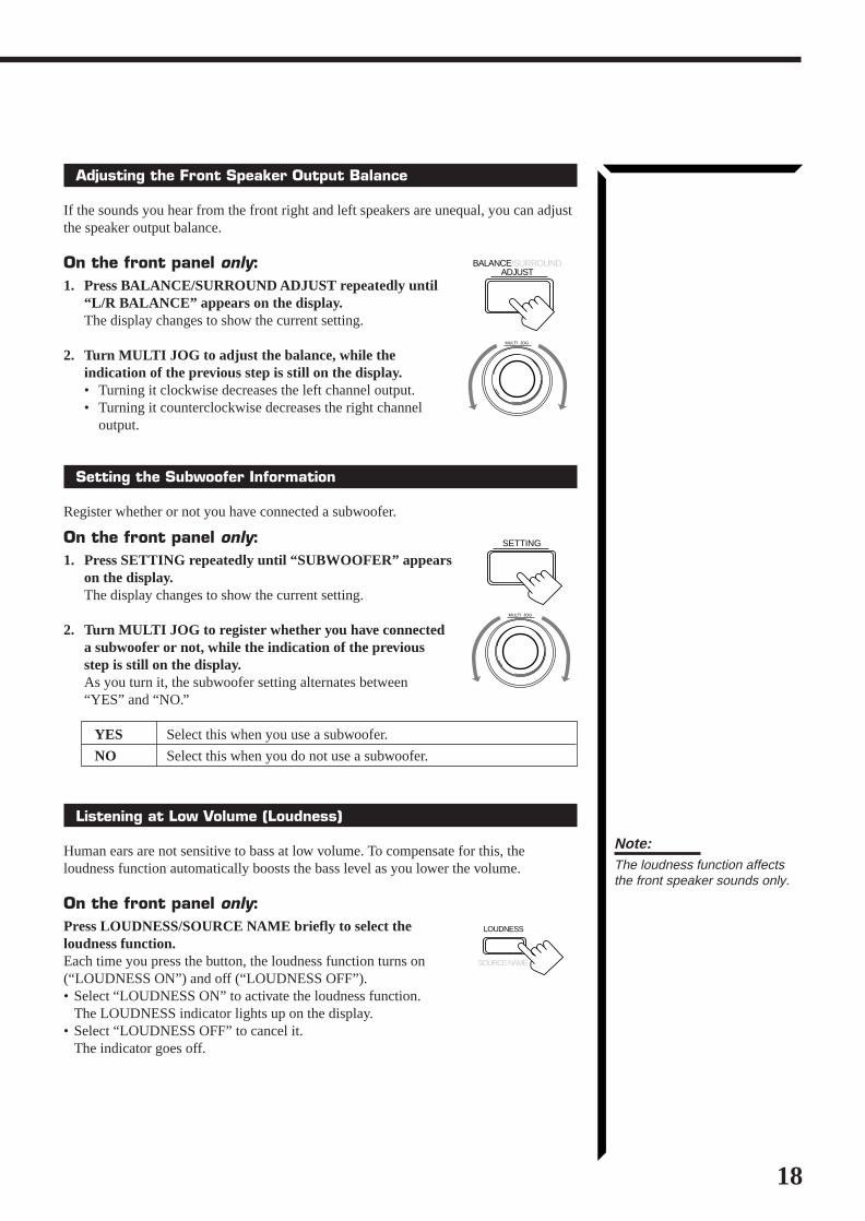
Adjusting the Front Speaker Output Balance
If the sounds you hear from the front right and left speakers are unequal, you can adjustthe speaker output balance.
On the front panel only:1. Press BALANCE/SURROUND ADJUST repeatedly until
“L/R BALANCE” appears on the display.The display changes to show the current setting.
2. Turn MULTI JOG to adjust the balance, while theindication of the previous step is still on the display.• Turning it clockwise decreases the left channel output.• Turning it counterclockwise decreases the right channel
output.
Setting the Subwoofer Information
Register whether or not you have connected a subwoofer.
On the front panel only:1. Press SETTING repeatedly until “SUBWOOFER” appears
on the display.The display changes to show the current setting.
2. Turn MULTI JOG to register whether you have connecteda subwoofer or not, while the indication of the previousstep is still on the display.As you turn it, the subwoofer setting alternates between“YES” and “NO.”
YES Select this when you use a subwoofer.
NO Select this when you do not use a subwoofer.
Listening at Low Volume (Loudness)
Human ears are not sensitive to bass at low volume. To compensate for this, theloudness function automatically boosts the bass level as you lower the volume.
On the front panel only:Press LOUDNESS/SOURCE NAME briefly to select theloudness function.Each time you press the button, the loudness function turns on(“LOUDNESS ON”) and off (“LOUDNESS OFF”).• Select “LOUDNESS ON” to activate the loudness function.
The LOUDNESS indicator lights up on the display.• Select “LOUDNESS OFF” to cancel it.
The indicator goes off.
Note:The loudness function affectsthe front speaker sounds only.
EN13_22.RX-1024V[J]/1.PM5 98.5.12, 0:18 PM18

19
Digital Input (DIGITAL IN) Terminal Setting
When you use the digital input terminals, you have to register what components areconnected to which terminals (DIGITAL IN 1/2/3).
On the front panel only:1. Press SETTING repeatedly until “DIGITAL IN”
appears on the display.The display changes to show the current setting.
2. Turn MULTI JOG to select the appropriate digital terminalsetting, while the indication of the previous step is still onthe display.As you turn it, the display changes to show the following:“ 1 DBS 2 DVD 3 CD “ 1 MD 2 DVD 3 CD “ 1 MD 2 DBS 3 CD“ 1 MD 2 DBS 3 DVD “ 1 CD 2 DVD 3 MD “ 1 CD 2 DBS 3 MD“ 1 CD 2 DBS 3 DVD “ 1 DVD 2 CD 3 MD “ 1 DVD 2 DBS 3 MD“ 1 DVD 2 DBS 3 CD “ 1DBS 2 CD 3 MD “ DBS 2 DVD 3 MD“ (back to the beginning)
Setting the Speakers for the DSP Modes
To obtain the best possible surround sound of the DSP modes, you have to register theinformation about the speakers arrangement after all connections are completed.
Front, Center, and Rear Speaker SettingRegister the sizes of the other speakers.
On the front panel only:1. Press SETTING repeatedly until “FRONT SPK” (Front
Speaker), “CENTER SPK” (Center Speaker) or “REARSPK” (Rear Speaker) appears on the display.The display changes to show the current setting.
2. Turn MULTI JOG to select the appropriate item aboutyour front, center and rear speakers, while the indication ofthe previous step is still on the display.As you turn it, the display changes to show the following:
LARGE Select this when the speaker size is relatively large.
SMALL Select this when the speaker size is relatively small.
NONE Select this when you have not connected a speaker. (Not selectablefor the front speakers)
Basic Settings
VOLUME
DIGITAL 2 terminal setting
DIGITAL 1 terminal setting DIGITAL 3 terminal setting
SETTING
Note:When you change yourspeakers, you need to registerthe information about thespeakers again.
Notes:• If the size of the cone speaker
unit built in your speaker isgreater than 4 3/4 inches (12cm ), select “LARGE,” and if itis smaller than 4 3/4 inches (12cm ), select “SMALL.”
• If you have selected “NO” forthe subwoofer setting, youcan only select “LARGE” forthe front speaker setting.
MULTI JOG
LARGE SMALL NONE
SETTING
MULTI JOG
Note:When shipped from the factory,the DIGITAL IN terminals can beused as the digital input for thefollowing components.• DIGITAL 1 (coaxial): For DBS
tuner• DIGITAL 2 (optical): For DVD
player• DIGITAL 3 (optical): For CD
player
EN13_22.RX-1024V[J]/1.PM5 98.5.12, 0:18 PM19

20
Center Delay Time SettingRegister the delay time of the sound from the center speaker, comparing that of thesound from the front speakers.If the distance from your listening point to the center speaker is equal to that to the frontspeakers, select 0 msec. As the distance to the center speaker becomes shorter, increasethe delay time.
On the front panel only:1. Press SETTING repeatedly until “CENTER DELAY”
appears on the display.The display changes to show the current setting.
2. Turn MULTI JOG to select the delay time of the centerspeaker output, while the indication of the previous step isstill on the display.• Turn it clockwise to increase the delay time from 0 msec
(“C. DELAY 0ms”) to 5 msec (“C. DELAY 5ms”).• Turn it counterclockwise to decrease the delay time from
5 msec (“C. DELAY 5ms”) to 0 msec (“C. DELAY0ms”).
Rear Delay Time SettingRegister the delay time of the sound from the rear speakers, comparing that of the soundfrom the front speakers.If the distance from your listening point to the rear speakers is equal to that to the frontspeakers, select 0 msec. As the distance to the rear speakers becomes shorter, increasethe delay time.
On the front panel only:1. Press SETTING repeatedly until “REAR DELAY” appears
on the display.The display changes to show the current setting.
2. Turn MULTI JOG to select the delay time of the rearspeaker output, while the indication of the previous step isstill on the display.• Turn it clockwise to increase the delay time from 0 msec
(“R. DELAY 0ms”) to 15 msec (“R. DELAY 15ms”).• Turn it counterclockwise to decrease the delay time from
15 msec (“R. DELAY 15ms”) to 0 msec (“R. DELAY0ms”).
Crossover Frequency SettingSmall speaker cannot reproduce the bass sound very well. So, if you have used a smallspeaker any for the front, center, or rear channels, this receiver automatically reallocatethe bass elements, originally assigned to the channel for which you have connected thesmall speaker, to another channel (for which you have connected the large speaker).To use this function properly, you need to set this crossover frequency level according tothe size of the small speaker connected.
On the front panel only:1. Press SETTING repeatedly until “CROSSOVER FRQ”
(Crossover Frequency) appears on the display.The display changes to show the current setting.
Note:1 msec increase (or decrease)in delay time corresponds to 1113/16 inches (30 cm) decrease (orincrease) in distance.
SETTING
MULTI JOG
SETTING
MULTI JOG
SETTING
Note:This function takes effect onlywhen playing back a sourcesusing the Dolby Digital.However, if you have selected“LARGE” for all speakers (seepage 19), this function will nottake effect.
Notes:• 1 msec increase (or
decrease) in delay timecorresponds to 11 13/16 inches(30 cm) decrease (orincrease) in distance.
• It is recommended that therear delay time for DolbyDigital be set to 5 msec.
EN13_22.RX-1024V[J]/1.PM5 98.5.12, 0:18 PM20

21
Basic Settings
CROSS: 80Hz CROSS:100Hz CROSS:120Hz
Note:This function takes effect onlywhen playing back a sourcesusing the Dolby Digital.
LFE ATT: 0dB LFE ATT:10dB
SETTING
MULTI JOG
SETTING
MULTI JOG
COMP.: OFF COMP.: MID COMP.: MAX
Note:This function takes effect onlywhen playing back a sourcesusing the Dolby Digital.
2. Turn MULTI JOG to select the crossover frequency levelaccording to the size of the small speaker connected, whilethe indication of the previous step is still on the display.As you turn it, the display changes to show the following:
CROSS: 80Hz Select this when the cone speaker unit built in the speaker isabout 4 3/4 inches (12 cm).
CROSS:100Hz Select this when the cone speaker unit built in the speaker isabout 3 15/16 inches (10 cm).
CROSS:120Hz Select this when the cone speaker unit built in the speaker isabout 3 3/16 inches (8 cm).
Low Frequency Effect Attenuator SettingIf the bass sound is distorted while playing back a source using Dolby Digital, followthe procedure below.
On the front panel only:1. Press SETTING repeatedly until “LFE ATT” (Low
Frequency Effect Attenuator) appears on the display.The display changes to show the current setting.
2. Turn MULTI JOG to select the low frequency effectattenuator level, while the indication of the previous step isstill on the display.As you turn it, the display changes to show the following:
LFE ATT: 0dB: Normally select this.
LFE ATT:10dB: Select this when the bass sound is distorted.
Dynamic Range Compression SettingYou can compress the dynamic range (difference between maximum sound andminimum sound) of the reproduced sound. This is useful when enjoying surround soundat night.
On the front panel only:1. Press SETTING repeatedly until “D. RANGE COMP.”
(Dynamic Range Compression) appears on the display.The display changes to show the current setting.
2. Turn MULTI JOG to select the appropriate item about thecompression level, while the indication of the previous stepis still on the display.As you turn it, the display changes to show the following:
COMP.: OFF Select this when you want to enjoy surround with its fulldynamic range. (No effect applied.)
COMP.: MID Select this when you want to reduce the dynamic range alittle. (Factory setting).
COMP.: MAX Select this when you want to apply the compression effectfully. (Useful at night).
EN13_22.RX-1024V[J]/1.PM5 98.5.12, 0:18 PM21

22
One Touch OperationThis receiver can memorize the optimum sound settings for each playing source.
About the One Touch Operation
JVC’s One Touch Operation function is used to assign and store different sound settingsfor each different playing source. By using this function, you do not have to change thesettings every time you change the source. The stored settings for the newly selectedsource are automatically recalled.
The following can be stored for each source:• Volume level (see page 14)• Input attenuator mode (see page 16)• Subwoofer output level (see page 16)• Input mode (see page 17)• Balance (see page 18)• Loudness (see page 18)• SEA modes (see page 26)• DSP modes
– 3D-PHONIC mode settings (see page 29)– DAP mode settings (see page 32)– Surround mode settings (see page 34 and 37)
Using the One Touch Operation
On the front panel only:To store the sound settings1. Press ONE TOUCH OPERATION.
The ONE TOUCH OPERATION lamp lights up, then thepreviously memorized settings are recalled.
2. Adjust the sound using the functions listed above.The newly adjusted settings are memorized.
To recall the sound settingsWith the ONE TOUCH OPERATION lamp lit, the settings for thecurrently selected source is recalled when the source is selected.
To cancel the One Touch Operation functionPress ONE TOUCH OPERATION so that the lamp goes off.(Even though the One Touch Operation function is canceled, therecalled sound effects remain active.)
Note:If the source is FM or AM, youcan assign a different setting foreach band.
ONE TOUCH OPERATION
ONE TOUCH OPERATION
EN13_22.RX-1024V[J]/1.PM5 98.5.12, 0:19 PM22

23
Receiving Radio BroadcastsYou can browse through all the stations or use the preset function to go immediately to a particularstation.
IMPORTANT:When using the Remote Control, check to see if its remote controlmode selector is set to the correct position:To operate this receiver, set it to “AUDIO/TV/VCR” (except whenselecting the DBS tuner as the source).
Tuning in Stations Manually
On the front panel:1. Press FM/AM TUNING to select the band.
Each time you press the button, the band alternates betweenFM and AM.
2. Turn MULTI JOG until you find the frequency youwant.• Turning it clockwise increases the frequency.• Turning it counterclockwise decreases the frequency.
From the remote control:1. Press FM or AM to select the band.
2. Press TUNING DOWN or TUNING UP repeatedlyuntil you find the frequency you want.
Using Preset Tuning
Once a station is assigned to a channel number, the station can be quickly tuned. Youcan preset up to 40 stations at random.
To store the preset stationsOn the front panel only:1. Tune in the station you want to preset (see above).
If you want to store the FM reception mode for this station, select the FM receptionmode you want. See page 24 for details.
2. Press TUNER/SEA MEMORY.“CH-” appears and the channel number position starts flashingon the display for about 5 seconds.
3. Turn MULTI JOG to select a channel number whilethe channel number position is flashing.
4. Press TUNER/SEA MEMORY again while theselected channel number is flashing on the display.The selected channel number stops flashing.The station is assigned to the selected channel number.
FM/AM TUNING
MULTI JOG
Notes:• When you turn MULTI JOG
quickly or hold the TUNINGUP or TUNING DOWN in step2, the frequency keepschanging until a station istuned in.
• When a station of sufficientsignal strength is tuned in, theTUNED indicator lights up onthe display.When an FM stereo programis received, the STEREOindicator also lights up.
TUNER/SEA MEMORY
MULTI JOG
TUNER/SEA MEMORY
Note:You can use the 10 keys on theremote control to select thepreset number. When using the10 keys, be sure that they areactivated for tuner, not for theCD and others. (See page 58.)
AM FM
/REW
DOWN TUNING
FF/
UP
AUDIO/TV/VCR
CATV
DBS
EN23_27.RX-1024V[J]/1.PM5 98.5.12, 0:24 PM23

24
5. Repeat steps 1 to 4 until you store all the stations youwant.
To erase a stored preset stationStoring a new station on a used number erases the previously stored one.
To tune in a preset stationOn the front panel:1. Press TUNER PRESET.
2. Turn MULTI JOG to select a preset channel.
From the remote control:1. Press FM or AM.
2. Press 10 keys to select a preset channel number.• For channel number 5, press 5.• For channel number 15, press +10 then 5.• For channel number 20, press +10 then 10.• For channel number 30, press +10, +10, then 10.
Selecting the FM Reception Mode
When an FM stereo broadcast is hard to receive or noisy, set the FM reception mode to“MONO.” (When shipped from the factory, this mode has been set to “AUTO.”)You can change the FM reception mode while receiving an FM broadcast.
Press FM MODE on the front panel or FM MODE/MUTE on the remote control.Each time you press the button, the FM reception modealternates between “AUTO” and “MONO.”
AUTO: When a program is broadcast in stereo, you will hear stereo sound;when in monaural, you will hear monaural sounds. This mode isalso useful to suppress static noise between stations.The MUTE AUTO indicator lights up on the display.
MONO: Reception will be improved although you will lose the stereo effect.In this mode, you will hear noise while tuning into the stations.The MUTE AUTO indicator goes off on the display.
MULTI JOG
FM MODE
TUNER PRESET
Notes:• You can store the FM
reception mode for eachpreset station.
• When using the FM MODE/MUTE button, be sure that the10 keys are activated fortuner, not for the CD andothers. (See page 58.)
Note:When you use the 10 keys onthe remote control, be sure thatthey are activated for tuner, notfor the CD and others. (Seepage 58.)
AM FM
FM MODE/MUTE
SUBWOOFER–
0
CNTR TONE CNTR– +
+10100+
10
1 2 3
TEST REAR · L
REAR · R
– +
4 5 6
EFFECT
SEA MODE
RETURN FM MODE/MUTE
– +
SUBWOOFER– +
7/P 8
0
9
ENTER
MENU
EN23_27.RX-1024V[J]/1.PM5 98.5.12, 0:24 PM24

25
Assigning Names to Preset Stations
You can assign a name of up to four characters to each preset station. When a presetstation is tuned in, its assigned name will appear on the display.
On the front panel only:1. Tune in a preset station.
See page 24 for details.
2. Press TUNER/SEA MEMORY.The preset channel number starts flashing for about 5 seconds.
3. Press TUNER PRESET, while the preset channel number isflashing.The first character position starts flashing.
4. Turn MULTI JOG to select the first character, whilethe first character position is flashing..You can use characters listed below.
5. Press TUNER PRESET, while a character you want isflashing.The next (or previous) character position starts flashing.
6. Repeat steps 4 and 5 to enter up to four characters.
7. Press TUNER/SEA MEMORY while the last selectedcharacter is flashing after you have assigned a name.
To erase the input charactersInsert spaces using the same procedure described above.
CH–
Available characters
Space
CBA D E GF H I J K L M N O
SRQ T U WV X Y Z 0 1 2 3 4P
876 95
MULTI JOG
Receiving Radio Broadcasts
CH–
VOLUME
CH–
VOLUME
CH–
VOLUME
Note:If you turn MULTI JOG while thepreset channel number isflashing, you can changethe preset channel number.
Note on step 3 to 7:You cannot select any entry afterthe indication on the displaystops flashing.In this case, repeat theprocedure from step 2 again.
TUNER/SEA MEMORY
MULTI JOG
TUNER PRESET
TUNER PRESET
TUNER/SEA MEMORY
EN23_27.RX-1024V[J]/1.PM5 98.5.12, 0:24 PM25

26
Using the SEA ModesThe SEA (Sound Effect Amplifier) modes give you control of the way your music sounds.
IMPORTANT:When using the Remote Control, check to see if its remote controlmode selector is set to the correct position:To operate this receiver, set it to “AUDIO/TV/VCR” (except whenselecting the DBS tuner as the source).
Selecting Your Favorite SEA Mode
On the front panel:1. Press SEA MODE.
The display changes to show the current setting.
2. Turn MULTI JOG until the mode you want appears on thedisplay, while the indication of the previous step is still onthe display.As you turn it, the SEA mode changes as follows:
SEA ROCK: Gives a heavy sound. Both high and low frequencies areboosted.
SEA MUSICAL: Enhance the mid-frequency range, which the human voice ismostly made up of.
SEA MOVIE: Adds breadth to sounds so you feel like you are in a movietheater.
SEA COUNTRY: Enhances the high-frequency range so that instruments suchas the violin and banjo are emphasized.
SEA JAZZ: Gives a feeling of a live atmosphere. Good for acoustic music.
SEA USERMODE: Your original SEA adjustment (see page 27).
SEA OFF: No SEA mode is applied (see below).
To cancel the SEA modeTurn MULTI JOG until “SEA OFF” appears in step 2 above.The SEA indicator goes off from the display.
From the remote control:1. Press SOUND.
10 keys are activated for sound adjustments.
2. Press SEA MODE repeatedly until the SEA mode you wantappears on the display.Each time you press the button, the SEA mode changesas follows:
To cancel the SEA modePress SEA MODE until “SEA OFF” appears in step 2 above.The SEA indicator goes off from the display.
Notes:• The SEA modes cannot be
used for recording.• When the SEA mode is turned
on, the SEA indicator lights upon the display.
• When the SEA mode is usedwith the DAP mode (see page32), sounds may be distorted.If this happens, turn off theDAP mode or decrease theeffect level of the DAP mode.
SEA MODE
SEA COUNTRY
SEA JAZZ
SEA ROCK SEA MUSICAL SEA MOVIE
SEA USERMODESEA OFF
SEA COUNTRY
SEA JAZZ
SEA ROCK SEA MUSICAL SEA MOVIE
SEA USERMODESEA OFF
Note:When the SEA mode is turnedon, the SEA indicator lights upon the display.
MULTI JOG
SOUND
10SEA MODE
RETURN
AUDIO/TV/VCR
CATV
DBS
EN23_27.RX-1024V[J]/1.PM5 98.5.12, 0:24 PM26

27
Creating Your Own SEA Mode
You can adjust and store your own SEA adjustment into memory (SEA USERMODE).
On the front panel only:If you do not want to store your adjustment, but rather want to adjust the SEAtemporarily, skip step 4 below.
1. Press SEA ADJUST repeatedly until the frequency range(100Hz, 1kHz or 10kHz) you want appears on the display.
2. Turn MULTI JOG to adjust the SEA level of the selectedfrequency range, while the indication of the previous step isstill on the display.• Turning it clockwise increases the level.• Turning it counterclockwise decreases the level.
3. Repeat step 1 and 2 to adjust other frequency ranges ifnecessary.
4. Press TUNER/SEA MEMORY, while the indication of theprevious step is still on the display.Your adjustment is stored into the SEA USERMODE.
To recall your own SEA adjustmentSee page 26.
To erase a stored adjustmentStoring a new adjustment into SEA USERMODE erases the previously stored one.
SEA ADJUST
MULTI JOG
100 1k 10k
VOLUME
FRS E A
100 1k 10k
VOLUME
FRS E A
Using the SEA Modes
100 1k 10k
FRS E A
This FR means this adjustment can beapplied to the front speakers only
TUNER/SEA MEMORY
EN23_27.RX-1024V[J]/1.PM5 98.5.12, 0:24 PM27

28
Using the DSP ModesThe built-in Surround Processor provides three types of the DSP (Digital Signal Processor) mode — 3D-PHONIC mode, DAP (Digital Acoustic Processor) mode and Surround mode (Dolby Digital, Dolby Pro Logicand JVC’s Theater Surround.)
On the 3D-PHONIC modeThe 3D-PHONIC mode gives you such anearly surround effect as it is reproducedthrough the Dolby Surround decoder, whichis widely used to reproduce sounds with afeeling of movement like those experiencedin movie theaters. The 3D-PHONIC mode isthe result of research on sound localizationtechnology carried out at JVC for manyyears and makes it possible to reproduce thesurround sound with only two frontspeakers.
On the DAP modeThe sound heard in a concert hall or clubconsists of direct sound and indirect sound— early reflections and reflections frombehind. Direct sounds reach the listenerdirectly without any reflection. On the otherhand, indirect sounds are delayed by thedistances of the ceiling and walls. Thesedirect sounds and indirect sounds are themost important elements of the acousticsurround effects. The DAP mode can createthese important elements, and gives you areal “being there” feeling.
On Surround modeWith this receiver, you can use two types ofthe surround mode.
Dolby Surround (Dolby Digital andDolby Pro Logic)Used to watch the soundtracks of softwareencoded with Dolby Digital (bearing themark
D I G I T A L) or with Dolby Surround
(bearing the mark DOLBY SURROUND ).Dolby Digital and Dolby Pro Logic can beselected automatically according tosoftware played back.
JVC’s Theater SurroundIn order to reproduce a more realistic sound field in your listening room while playingsoundtracks of software encoded with Dolby Digital (bearing the mark
D I G I T A L) or
with Dolby Surround (bearing the mark DOLBY SURROUND ), Theater Surround has beendesigned to create a real “being there” feeling.
Early reflections
Reflections frombehind
Direct sounds
Notes:• The DSP modes have no
effect on monaural sources.• You can not use the two types
of the DSP modes at the sametime.
Note:To enjoy the software encodedwith Dolby Digital, you mustconnect the source componentusing the digital terminal on therear of this receiver.
Manufactured under licensefrom Dolby Laboratories.“Dolby,” “Pro Logic,” and thedouble-D symbol are trademarksof Dolby Laboratories.Confidential Unpublished Works.©1992–1997 DolbyLaboratories, Inc. All rightsreserved.
IMPORTANT:
When recording the digitalsource, turn off the DSP mode.
EN28_40.RX-1024V[J]/1.PM5 98.5.12, 0:26 PM28
29
Using the DSP Modes
IMPORTANT:When using the Remote Control, check to see if its remote controlmode selector is set to the correct position:To operate this receiver, set it to “AUDIO/TV/VCR” (except whenselecting the DBS tuner as the source).
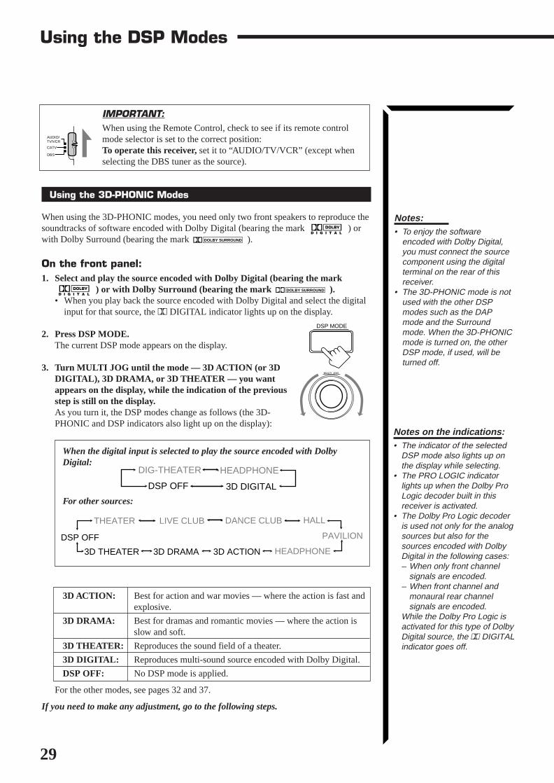
Using the 3D-PHONIC Modes
When using the 3D-PHONIC modes, you need only two front speakers to reproduce thesoundtracks of software encoded with Dolby Digital (bearing the mark
D I G I T A L) or
with Dolby Surround (bearing the mark DOLBY SURROUND ).
On the front panel:1. Select and play the source encoded with Dolby Digital (bearing the mark
D I G I T A L) or with Dolby Surround (bearing the mark DOLBY SURROUND ).
• When you play back the source encoded with Dolby Digital and select the digitalinput for that source, the Ÿ DIGITAL indicator lights up on the display.
2. Press DSP MODE.The current DSP mode appears on the display.
3. Turn MULTI JOG until the mode — 3D ACTION (or 3DDIGITAL), 3D DRAMA, or 3D THEATER — you wantappears on the display, while the indication of the previousstep is still on the display.As you turn it, the DSP modes change as follows (the 3D-PHONIC and DSP indicators also light up on the display):
When the digital input is selected to play the source encoded with DolbyDigital:
For other sources:
3D ACTION: Best for action and war movies — where the action is fast andexplosive.
3D DRAMA: Best for dramas and romantic movies — where the action isslow and soft.
3D THEATER: Reproduces the sound field of a theater.
3D DIGITAL: Reproduces multi-sound source encoded with Dolby Digital.
DSP OFF: No DSP mode is applied.
For the other modes, see pages 32 and 37.
If you need to make any adjustment, go to the following steps.
MULTI JOG
DSP MODE
Notes:• To enjoy the software
encoded with Dolby Digital,you must connect the sourcecomponent using the digitalterminal on the rear of thisreceiver.
• The 3D-PHONIC mode is notused with the other DSPmodes such as the DAPmode and the Surroundmode. When the 3D-PHONICmode is turned on, the otherDSP mode, if used, will beturned off.
Notes on the indications:• The indicator of the selected
DSP mode also lights up onthe display while selecting.
• The PRO LOGIC indicatorlights up when the Dolby ProLogic decoder built in thisreceiver is activated.
• The Dolby Pro Logic decoderis used not only for the analogsources but also for thesources encoded with DolbyDigital in the following cases:– When only front channel
signals are encoded.– When front channel and
monaural rear channelsignals are encoded.
While the Dolby Pro Logic isactivated for this type of DolbyDigital source, the Ÿ DIGITALindicator goes off.
HALLDANCE CLUBLIVE CLUBTHEATER
3D ACTION HEADPHONE3D DRAMA
PAVILION
3D THEATER
DSP OFF
AUDIO/TV/VCR
CATV
DBS
DIG-THEATER HEADPHONE
3D DIGITALDSP OFF
EN28_40.RX-1024V[J]/1.PM5 98.5.12, 0:26 PM29

30
4. Press BALANCE/SURROUND ADJUST repeatedly until“DSP EFFECT” appears on the display.The display changes to show the current setting.
5. Turn MULTI JOG to select the effect level, while the indication ofthe previous step is still on the display.As you turn it, the effect level changes as follows:
As the number increases, the selected 3D-PHONIC modebecomes stronger.
To cancel the 3D-PHONIC modeTurn MULTI JOG until “DSP OFF” appears in step 3.The 3D-PHONIC and DSP indicators go off from the display.
Note:Once you have adjusted the 3D-PHONIC modes, it is memorizedfor each 3D-PHONIC mode.
BALANCE/SURROUNDADJUST
MULTI JOG
DSP EFFECT 1 DSP EFFECT 2
DSP EFFECT 4
DSP EFFECT 3
DSP EFFECT 5
EN28_40.RX-1024V[J]/1.PM5 98.5.12, 0:26 PM30

31
From the remote control:1. Select and play the source encoded with Dolby Digital (bearing the mark
D I G I T A L) or with Dolby Surround (bearing the mark DOLBY SURROUND ).
• When you play back the source encoded with Dolby Digital and select the digitalinput for that source, the Ÿ DIGITAL indicator lights up on the display.
2. Press SURROUND MODE repeatedly until the mode — 3DACTION (or 3D DIGITAL), 3D DRAMA, or 3D THEATER— you want appears on the display.Each time you press the button, the DSP modes change asfollows (the 3D-PHONIC and DSP indicators also light upon the display):
When the digital input is selected to play the source encoded with DolbyDigital:
For other sources:
3. Press SOUND.10 keys are activated for sound adjustments.
4. Press EFFECT to select the effect level.Each time you press the button, the effect level changes as follows:
As the number increases, the selected 3D-PHONIC mode becomesstronger.
To cancel the 3D-PHONIC modePress SURROUND MODE repeatedly until “OFF” appears.The 3D-PHONIC and DSP indicators go off from the display.
HALLDANCE CLUBLIVE CLUBTHEATERPRO LOGIC
3D ACTION HEADPHONE3D DRAMAPAVILION
3D THEATER
OFF
DSP EFFECT 1 DSP EFFECT 2
DSP EFFECT 4
DSP EFFECT 3
DSP EFFECT 5
Using the DSP Modes
DOLBY DIGITAL DIG-THEATER
HEADPHONE3D DIGITALOFF
Note:The 3D-PHONIC mode is notused with the other DSP modessuch as the DAP mode and theSurround mode. When the 3D-PHONIC mode is turned on, theother DSP mode, if used, will beturned off.
Note:Once you have adjusted the 3D-PHONIC modes, it is memorizedfor each 3D-PHONIC mode.
Notes on the indications:• The indicator of the selected
DSP mode also lights up onthe display while selecting.
• The PRO LOGIC indicatorlights up when the Dolby ProLogic decoder built in thisreceiver is activated.
• The Dolby Pro Logic decoderis used not only for the analogsources but also for thesources encoded with DolbyDigital in the following cases:– When only front channel
signals are encoded.– When front channel and
monaural rear channelsignals are encoded.
While the Dolby Pro Logic isactivated for this type of DolbyDigital source, the Ÿ DIGITALindicator goes off.
MODE
SURROUND
SOUND
EFFECT
7
EN28_40.RX-1024V[J]/1.PM5 98.5.12, 0:26 PM31

32
Using the DAP Modes
You can use five DAP modes — “Live Club, Dance Club, Hall, Pavilion, andHeadphones” for any source.Among the DAP modes, “Headphones” is very special. It can create the same stereosound as you listen through the speakers off air while listening to a source usingheadphones. So, you can feel as if you were not using the headphones and listening tomusic in a room.If the digital input is selected to play the source encoded with Dolby Digital, you canonly select “Headphones.”
On the front panel:1. Press DSP MODE.
The current DSP mode appears on the display.
2. Turn MULTI JOG until the mode (LIVE CLUB, DANCECLUB, HALL, PAVILION, or HEADPHONE) you wantappears on the display, while the indication of the previousstep is still on the display.The DSP indicator also lights up on the display.
As you turn it, the DSP modes change as follows:
When the digital input is selected to play the source encoded with DolbyDigital:
LIVE CLUB: Gives the feeling of a live music club with a low ceiling.
DANCE CLUB: Gives a throbbing bass beat.
HALL: Gives clear vocal and the feeling of a concert hall.
PAVILION: Gives the spacious feeling of a pavilion with a high ceiling.
HEADPHONE: Gives a spacious stereo effect when listening with headphones.
DSP OFF: No DSP mode is applied.
For the other modes, see pages 29 and 37.
If you need to make any adjustment, go to the following steps.
3. Adjust the speaker output levels as follows.1) Press BALANCE/SURROUND ADJUST repeatedly
until one of the indications appears on the display.“REAR L LEVEL”: To adjust the left speaker level.“REAR R LEVEL”: To adjust the right speaker level.
2) Turn MULTI JOG to adjust the selected speaker outputlevel (from –10 dB to +10 dB), while the indication of theprevious step is still on the display.
3) Repeat 1) and 2) to adjust the other speaker outputlevels.
Notes:• The DAP mode is not used
with the other DSP modessuch as the 3D-PHONICmode and the Surroundmode. When the DAP modeis turned on, the other DSPmode, if used, will be turnedoff.
• When the DAP mode is usedwith the SEA mode (see page26), sounds may be distorted.If this happens, turn off theSEA mode.
Note:The indicator of the selectedDSP mode also lights up on thedisplay while selecting.HALLDANCE CLUBLIVE CLUBTHEATER
3D ACTION HEADPHONE3D DRAMA
PAVILION
3D THEATER
DSP OFF
DIG-THEATER HEADPHONE
3D DIGITALDSP OFF
Note:When you select“HEADPHONE,” you cannot goto the following steps. Noadjustments can be made forHEADPHONE.”
Note:You cannot adjust the rearspeaker levels when “REARSPK” is set to “NONE” (seepage 19).
MULTI JOG
MULTI JOG
DSP MODE
BALANCE/SURROUNDADJUST
Continued to the next page.
EN28_40.RX-1024V[J]/1.PM5 98.5.12, 0:26 PM32

33
4. Adjust the effect level.1) Press BALANCE/SURROUND ADJUST repeatedly
until “DSP EFFECT” appears on the display.2) Turn MULTI JOG to select the effect level, while the
indication of the previous step is still on the display.As you turn it, the effect level changes as follows:
As the number increases, the selected DAP modebecomes stronger.
To cancel the DAP modeTurn MULTI JOG until “DSP OFF” appears in step 2.The DSP indicator goes off from the display.
From the remote control:1. Press SURROUND MODE repeatedly until the mode you
want appears on the display.The DSP indicator also lights up on the display.
Each time you press the button, the DSP modes change as follows (the indicatorof the selected DSP mode also lights up on the display):
When the digital input is selected to play the source encoded with DolbyDigital:
If you need to make any adjustment, go to the following steps.
2. Press SOUND.10 keys are activated for sound adjustments.
3. Adjust the speaker output levels as follows:• To adjust the left rear speaker level, press REAR•L +/–.• To adjust the right rear speaker level, press REAR•R +/–.
4. Press EFFECT to select the effect level.Each time you press the button, the effect level changes asfollows:
As the number increases, the selected DAP mode becomesstronger.
To cancel the DAP modePress SURROUND MODE repeatedly until “OFF” appears.The DSP indicator goes off from the display.
BALANCE/SURROUNDADJUST
Note:Once you have adjusted theDAP modes, the adjustment ismemorized for each DAP mode.
Note:The DAP mode is not used withthe other DSP modes such asthe 3D-PHONIC mode and theSurround mode. When the DAPmode is turned on, the otherDSP mode, if used, will beturned off.
MULTI JOGDSP EFFECT 1 DSP EFFECT 2
DSP EFFECT 4
DSP EFFECT 3
DSP EFFECT 5
HALLDANCE CLUBLIVE CLUBTHEATERPRO LOGIC
3D ACTION HEADPHONE3D DRAMAPAVILION
3D THEATER
OFF
Note:Once you have adjusted theDAP modes, the adjustment ismemorized for each DAP mode.
DSP EFFECT 1 DSP EFFECT 2
DSP EFFECT 4
DSP EFFECT 3
DSP EFFECT 5
Using the DSP Modes
DOLBY DIGITAL DIG-THEATER
HEADPHONE3D DIGITALOFF
Note:When you select“HEADPHONE,” you cannot goto the following steps. Noadjustments can be made for“HEADPHONE.”
Note:You cannot adjust the rearspeaker levels when “REARSPK” is set to “NONE” (seepage 19).
MODE
SURROUND
SOUND
REAR · L– +
5 6ENTER
REAR · R– +
8 9
EFFECT
7/P
EN28_40.RX-1024V[J]/1.PM5 98.5.12, 0:26 PM33

34
Using the Dolby Digital and Dolby Pro Logic Modes
Once you have adjusted the Dolby Digital and Dolby Pro Logic modes, this receivermemorizes adjustment for each mode.To activate the Dolby Digital and Dolby Pro Logic modes, follow the procedure below.
From the remote control:1. Select and play the source encoded with Dolby Digital (bearing the mark
D I G I T A L) or with Dolby Surround (bearing the mark DOLBY SURROUND ).
• When you play back the source encoded with Dolby Digital and select the digitalinput for that source, the Ÿ DIGITAL indicator lights up on the display.
2. Press SURROUND MODE repeatedly until “PRO LOGIC”or “DOLBY DIGITAL” appears on the display.Dolby Digital or Dolby Pro Logic is automatically selectedaccording to the source being played back.
When Dolby Pro Logic is selected, the lamp on the DOLBY SURROUND button(on the front panel) lights red.
When Dolby Digital is selected, the lamp on the DOLBY SURROUND button (onthe front panel) lights green.
Each time you press the button, the DSP modes change as follows:
When the digital input is selected to play the source encoded with DolbyDigital:
For other sources:
If you need to make any adjustment, go to the following steps.
3. Press SOUND.10 keys are activated for sound adjustments.
Notes:• To enjoy the software encoded
with Dolby Digital, you mustconnect the sourcecomponent using the digitalterminal on the rear of thisreceiver.
• When the signals come intothis receiver through theanalog connection from thesource component, “PROLOGIC” is automaticallyselected.
• The Surround mode is notused with the other DSPmodes such as the DAP modeand 3D-PHONIC mode. Whenthe Surround mode is turnedon, the other DSP mode, ifused, will be turned off.
Notes on the indications:• The PRO LOGIC indicator
lights up when the Dolby ProLogic decoder built in thisreceiver is activated.
• The Dolby Pro Logic decoderis used not only for the analogsources but also for thesources encoded with DolbyDigital in the following cases:– When only front channel
signals are encoded.– When front channel and
monaural rear channelsignals are encoded.
While the Dolby Pro Logic isactivated for this type of DolbyDigital source, the Ÿ DIGITALindicator goes off.
DOLBY DIGITAL DIG-THEATER
HEADPHONE3D DIGITALOFF
HALLDANCE CLUBLIVE CLUBTHEATERPRO LOGIC
3D ACTION HEADPHONE3D DRAMAPAVILION
3D THEATER
OFF
Continued to the next page.
MODE
SURROUND
SOUND
EN28_40.RX-1024V[J]/1.PM5 98.5.12, 0:26 PM34

35
4. Press TEST to start checking the speaker output balance.“TEST TONE L” starts flashing on the display, and a testtone comes out of the speakers in the following order:
IMPORTANT:• Output the test tone while playing back an audio source.
With the DVD digital input selected as the source, no test tone may come out whileno signal is input to this receiver.
• Test tone comes out even while playing back a source encoded with Dolby Digital. Inthis case, the PRO LOGIC indicator lights up on the display.
5. Adjust the speaker output levels as follows:• To adjust the center speaker level, press CNTR +/–.• To adjust the left rear speaker level, press REAR•L +/–.• To adjust the right rear speaker level, press REAR•R +/–.
6. Press TEST again to stop the test tone.
7. Press CNTR TONE to select the center tone level you want.The center tone adjustment affects the mid-frequencyrange, which the human voice is mostly made up of.Each time you press the button, the display changes toshow the following:
Adjusted levels are also shown on the equalizer display.
To make the dialogue clearer, select “SHARP1” (little) or “SHARP2” (much).To make the dialogue softer, select “SOFT1” (little) or “SOFT2” (much).When “FLAT” is selected, no adjustment is applied.
To cancel the Surround modePress SURROUND MODE repeatedly until “OFF” appears.
Using the DSP Modes
(Left front speaker) (Center speaker) (Right front speaker)
(Left rear speaker) (Right rear speaker)
TEST TONE L TEST TONE C TEST TONE R
TEST TONE RSTEST TONE LS
The speaker indicators also light on the display while the test tonecomes out of the speakers.L: Lights when the test tone comes out of the left front speaker.C: Lights when the test tone comes out of the center speaker.R: Lights when the test tone comes out of the right front speaker.RS: Lights when the test tone comes out of the right rear speaker.LS: Lights when the test tone comes out of the left rear speaker.
C
LS
L
RS
R
Notes:• No test tone comes out of the
center speakers when“CENTER SPK” is set to“NONE” (see page 19).
• No test tone comes out of therear speakers when “REARSPK” is set to “NONE” (seepage 19).
• If the TV is turned on and theproper video input is selectedon the TV, the test tonescreen will appear on the TV.
Notes:• You can adjust the speaker
output levels and center tonewithout outputting the testtone.
• You cannot adjust the centerspeaker output level when“CENTER SPK” is set to“NONE” (see page 19).
• You cannot adjust the rearspeaker levels when “REARSPK” is set to “NONE” (seepage 19).
Note:The center tone cannot beadjusted when “CENTER SPK”is set to “NONE” (see page 19).
SHARP1 SHARP2FLATSOFT2 SOFT1
CNTR
100 1k 10k
S E A
This CNTR means this adjustment can beapplied to the center speaker only.(Example: When “FLAT” is selected.)
TEST
4
CNTR– +
2 3 MENU
REAR · L– +
5 6ENTER
REAR · R– +
8 9
TEST
4
CNTR TONE
1
EN28_40.RX-1024V[J]/1.PM5 98.5.12, 0:26 PM35

36
Notes:• To enjoy the software encoded
with Dolby Digital, you mustconnect the sourcecomponent using the digitalterminal on the rear of thisreceiver.
• When the signals come intothis receiver through theanalog connection from thesource component, “PROLOGIC” is automaticallyselected.
• The Surround mode is notused with the other DSPmodes such as the DAP modeand 3D-PHONIC mode. Whenthe Surround mode is turnedon, the other DSP mode, ifused, will be turned off.
On the front panel:You can also use the buttons on the front panel to adjust the Dolby Digital and DolbyPro Logic modes. However, no test tone is available when using the buttons on the frontpanel. So, make adjustments while listening to the sound of the source played back.
1. Select and play the source encoded with Dolby Digital (bearing the mark
D I G I T A L) or with Dolby Surround (bearing the mark DOLBY SURROUND ).
• When you play back the source encoded with Dolby Digital and select the digitalinput for that source, the Ÿ DIGITAL indicator lights up on the display.
2. Press DOLBY SURROUND so that the lamp on the buttonlights up.“SURROUND ON” appears on the display.Dolby Digital or Dolby Pro Logic is automatically selectedaccording to the source being played back.
When Dolby Pro Logic is selected, the lamp on the DOLBY SURROUND buttonlights red.
When Dolby Digital is selected, the lamp on the DOLBY SURROUND button lightsgreen.
If you need to make any adjustment, go to the following steps.
3. Adjust the speaker output levels as follows.1) Press BALANCE/SURROUND ADJUST repeatedly
until one of the indications appears on the display.“CENTER LEVEL”: To adjust the center speaker level.“REAR L LEVEL”: To adjust the left speaker level.“REAR R LEVEL”: To adjust the right speaker level.
2) Turn MULTI JOG to adjust the selected speaker outputlevel (from –10 dB to +10 dB), while the indicator of theprevious step is still on the display.
3) Repeat 1) and 2) to adjust the other speaker outputlevels.
4. Press BALANCE/SURROUND ADJUST repeatedly until“CENTER TONE” appears on the display.The display changes to show the current setting.
5. Turn MULTI JOG to select the center tone level you want,while the indication of the previous step is still on thedisplay.The center tone adjustment affects the mid-frequencyrange, which the human voice is mostly made up of.As you turn it, the display changes to show thefollowing:
To make the dialogue clearer, select “SHARP1” (little) or “SHARP2” (much).To make the dialogue softer, select “SOFT1” (little) or “SOFT2” (much).When “FLAT” is selected, no adjustment is applied.
To cancel the surround modePress DOLBY SURROUND again so that “SURROUND OFF” appears.
MULTI JOG
BALANCE/SURROUNDADJUST
DOLBY SURROUND
BALANCE/SURROUNDADJUST
MULTI JOG Notes:• You cannot adjust the center
speaker level when “CENTERSPK” is set to “NONE” (seepage 19).
• You cannot adjust the rearspeaker levels when “REARSPK” is set to “NONE” (seepage 19).SHARP1 SHARP2FLATSOFT2 SOFT1
Notes on the indications:• The PRO LOGIC indicator
lights up when the Dolby ProLogic decoder built in thisreceiver is activated.
• The Dolby Pro Logic decoderis used not only for the analogsources but also for thesources encoded with DolbyDigital in the following cases:– When only front channel
signals are encoded.– When front channel and
monaural rear channelsignals are encoded.
While the Dolby Pro Logic isactivated for this type of DolbyDigital source, the Ÿ DIGITALindicator goes off.
EN28_40.RX-1024V[J]/1.PM5 98.5.12, 0:26 PM36

37
Using the Theater Surround Mode
Once you have adjusted the Theater Surround mode, this receiver memorizes theadjustment. To activate the Theater Surround mode, follow the procedure below.
From the remote control:1. Select and play the source encoded with Dolby Digital (bearing the mark
D I G I T A L) or with Dolby Surround (bearing the mark DOLBY SURROUND ).
• When you play back the source encoded with Dolby Digital and select the digitalinput for that source, the Ÿ DIGITAL indicator lights up on the display.
2. Press SURROUND MODE repeatedly until “THEATER”or “DIG-THEATER” appears on the display.The DSP and THEATER indicators also light up on the display.
Each time you press the button, the DSP modes change as follows:
When the digital input is selected to play the source encoded with DolbyDigital:
For other sources:
If you need to make any adjustment, go to the following steps.
3. Press SOUND.10 keys are activated for sound adjustments.
4. Press TEST to start checking the speaker output balance.“TEST TONE L” starts flashing on the display, and a testtone comes out of the speakers in the following order:
Notes:• To enjoy the software encoded
with Dolby Digital, you mustconnect the sourcecomponent using the digitalterminal on the rear of thisreceiver.
• The Surround mode is notused with the other DSPmodes such as the DAP modeand 3D-PHONIC mode. Whenthe Surround mode is turnedon, the other DSP mode, ifused, will be turned off.
Using the DSP Modes
Notes on the indications:• The PRO LOGIC indicator
lights up when the Dolby ProLogic decoder built in thisreceiver is activated.
• The Dolby Pro Logic decoderis used not only for the analogsources but also for thesources encoded with DolbyDigital in the following cases:– When only front channel
signals are encoded.– When front channel and
monaural rear channelsignals are encoded.
While the Dolby Pro Logic isactivated for this type of DolbyDigital source, the Ÿ DIGITALindicator goes off.
DOLBY DIGITAL DIG-THEATER
HEADPHONE3D DIGITALOFF
HALLDANCE CLUBLIVE CLUBTHEATERPRO LOGIC
3D ACTION HEADPHONE3D DRAMAPAVILION
3D THEATER
OFF
(Left front speaker) (Center speaker) (Right front speaker)
(Left rear speaker) (Right rear speaker)
TEST TONE L TEST TONE C TEST TONE R
TEST TONE RSTEST TONE LS
Notes:• No test tone comes out of the
center speakers when“CENTER SPK” is set to“NONE” (see page 19).
• No test tone comes out of therear speakers when “REARSPK” is set to “NONE” (seepage 19).
• If the TV is turned on and theproper video input is selectedon the TV, the test tonescreen will appear on the TV.The speaker indicators also light on the display while the test tone
comes out of the speakers.L: Lights when the test tone comes out of the left front speaker.C: Lights when the test tone comes out of the center speaker.R: Lights when the test tone comes out of the right front speaker.RS: Lights when the test tone comes out of the right rear speaker.LS: Lights when the test tone comes out of the left rear speaker.
C
LS
L
RS
R
IMPORTANT:• Output the test tone while playing back an audio source.
With the DVD digital input selected as the source, no test tone may come out whileno signal is input to this receiver.
• Test tone comes out even while playing back a source encoded with Dolby Digital. Inthis case, the PRO LOGIC indicator lights up on the display.
MODE
SURROUND
SOUND
TEST
4
EN28_40.RX-1024V[J]/1.PM5 98.5.12, 0:26 PM37

38
5. Adjust the speaker output levels as follows:• To adjust the center speaker level, press CNTR +/–.• To adjust the left rear speaker level, press REAR•L +/–.• To adjust the right rear speaker level, press REAR•R +/–.
6. Press TEST again to stop the test tone.
7. Press CNTR TONE to select the center tone level you want.The center tone adjustment affects the mid-frequencyrange, which the human voice is mostly made up of.Each time you press the button, the display changes toshow the following:
Adjusted levels are also shown on the equalizer display.
To make the dialogue clearer, select “SHARP1” (little) or “SHARP2” (much).To make the dialogue softer, select “SOFT1” (little) or “SOFT2” (much).When “FLAT” is selected, no adjustment is applied.
8. Press EFFECT to select the effect level.Each time you press the button, the effect level changesas follows:
As the number increases, the surround effect becomesstronger.
To cancel the Theater Surround modePress SURROUND MODE repeatedly until “OFF” appears.The DSP and THEATER indicators goes off.
Notes:• You can adjust the speaker
output levels and center tonewithout outputting the testtone.
• You cannot adjust the centerspeaker level when “CENTERSPK” is set to “NONE” (seepage 19).
• You cannot adjust the rearspeaker levels when “REARSPK” is set to “NONE” (seepage 19).
SHARP1 SHARP2FLATSOFT2 SOFT1
Note:The center tone cannot beadjusted when “CENTER SPK”is set to “NONE” (see page 19).
CNTR– +
2 3 MENU
REAR · R– +
8 9REAR · L– +
5 6ENTER
TEST
4
CNTR TONE
1
CNTR
100 1k 10k
S E A
This CNTR means this adjustment can beapplied to the center speaker only.(Example: When “FLAT” is selected.)
DSP EFFECT 1 DSP EFFECT 2
DSP EFFECT 4
DSP EFFECT 3
DSP EFFECT 5
Note:You cannot adjust the effectlevel when “REAR SPK” is setto “NONE” (see page 19).
EFFECT
7/P
EN28_40.RX-1024V[J]/1.PM5 98.5.12, 0:26 PM38

39
Notes:• To enjoy the software encoded
with Dolby Digital, you mustconnect the sourcecomponent using the digitalterminal on the rear of thisreceiver.
• The Surround mode is notused with the other DSPmodes such as the DAP modeand 3D-PHONIC mode. Whenthe Surround mode is turnedon, the other DSP mode, ifused, will be turned off.
On the front panel:You can also use the buttons on the front panel to adjust the Theater Surround mode.However, no test tone is available when using the buttons on the front panel. So, makeadjustments while listening to the sound of the source played back.
1. Select and play the source encoded with Dolby Digital (bearing the mark
D I G I T A L) or with Dolby Surround (bearing the mark DOLBY SURROUND ).
• When you play back the source encoded with Dolby Digital and select the digitalinput for that source, the Ÿ DIGITAL indicator lights up on the display.
2. Press DSP MODE.The current DSP mode appears on the display.
3. Turn MULTI JOG until “THEATER” or “DIG-THEATER” appears on the display, while the indication ofthe previous step is still on the display.The DSP and THEATER indicators also light up on the display.
As you turn it, the DSP modes change as follows:
When the digital input is selected to play the source encoded with DolbyDigital:
For other sources:
If you need to make any adjustment, go to the following steps.
4. Adjust the speaker output levels as follows.1) Press BALANCE/SURROUND ADJUST repeatedly
until one of the indications appears on the display.“CENTER LEVEL”: To adjust the center speaker level.“REAR L LEVEL”: To adjust the left speaker level.“REAR R LEVEL”: To adjust the right speaker level.
2) Turn MULTI JOG to adjust the selected speaker outputlevel (from –10 dB to +10 dB), while the indication of theprevious step is still on the display.
3) Repeat 1) and 2) to adjust the other speaker outputlevels.
Using the DSP Modes
MULTI JOG
DSP MODE
MULTI JOG
BALANCE/SURROUNDADJUST Notes:
• You cannot adjust the centerspeaker level when “CENTERSPK” is set to “NONE” (seepage 19).
• You cannot adjust the rearspeaker levels when “REARSPK” is set to “NONE” (seepage 19).
HALLDANCE CLUBLIVE CLUBTHEATER
3D ACTION HEADPHONE3D DRAMA
PAVILION
3D THEATER
DSP OFF
Notes on the indications:• The PRO LOGIC indicator
lights up when the Dolby ProLogic decoder built in thisreceiver is activated.
• The Dolby Pro Logic decoderis used not only for the analogsources but also for thesources encoded with DolbyDigital in the following cases:– When only front channel
signals are encoded.– When front channel and
monaural rear channelsignals are encoded.
While the Dolby Pro Logic isactivated for this type of DolbyDigital source, the Ÿ DIGITALindicator goes off.
DIG-THEATER HEADPHONE
3D DIGITALDSP OFF
EN28_40.RX-1024V[J]/1.PM5 98.5.12, 0:27 PM39

40
5. Press BALANCE/SURROUND ADJUST repeatedlyuntil “CENTER TONE” appears on the display.The display changes to show the current setting.
6. Turn MULTI JOG to select the center tone level you want,while the indication of the previous step is still on thedisplay.The center tone adjustment affects the mid-frequencyrange, which the human voice is mostly made up of.As you turn it, the display changes to show thefollowing:
7. Press BALANCE/SURROUND ADJUST repeatedlyuntil “DSP EFFECT” appears on the display.The display changes to show the current setting.
8. Turn MULTI JOG to select the effect level, while theindication of the previous step is still on the display.As you turn it, the effect level changes as follows:
As the number increases, the surround effect becomesstronger.
To cancel the Theater Surround modeTurn MULTI JOG until “DSP OFF” appears in step 3.The DSP and THEATER indicators goes off.
MULTI JOG
SHARP1 SHARP2FLATSOFT2 SOFT1
BALANCE/SURROUNDADJUST
BALANCE/SURROUNDADJUST
DSP EFFECT 1 DSP EFFECT 2
DSP EFFECT 4
DSP EFFECT 3
DSP EFFECT 5
MULTI JOG
Note:You cannot adjust the effectlevel when “REAR SPK” is setto “NONE” (see page 19).
EN28_40.RX-1024V[J]/1.PM5 98.5.12, 0:27 PM40

41
MAIN MENU
SOURCE :ch 1 FM 87.5 MHz VISUAL :VCR1 MODE :OFF SOUND CONTROL TUNER CONTROL SETTING VOLUME : 20
:OPERATE
******
******
Using the On-Screen MenusYou can use the menus on the TV screen to control the receiver.To use this function, you need to connect the TV to the MONITOR OUT jack on the rear panel (see page 9),and set the TV’s input mode to the proper position to which the receiver is connected.
Selecting the Source to Play (Also see page 13)
1. Press any button of ON SCREEN CONTROL % / fi / @ / # once.The MAIN MENU appears on the TV.
2. Press ON SCREEN CONTROL % / fi to move to “SOURCE.”
3. Press ON SCREEN CONTROL @ / # to select the source.
4. When you finish, press EXIT.The menu disappears from the TV.
Selecting the Different Sources for Picture and Sound
You can view the pictures played back on a video component while listening to anysource.
1. Press any button of ON SCREEN CONTROL % / fi / @ / # once.The MAIN MENU appears on the TV.
2. Press ON SCREEN CONTROL % / fi to move to “VISUAL.”
3. Press ON SCREEN CONTROL @ / # to select a different video source.• When you select “OSD,” see page 49.
4. When you finish, press EXIT.The menu disappears from the TV.
Using the DSP Modes (Also see pages 29, 32, 34, 37)
1. Press any button of ON SCREEN CONTROL % / fi / @ / # once.The MAIN MENU appears on the TV.
2. Press ON SCREEN CONTROL % / fi to move to “MODE.”
3. Press ON SCREEN CONTROL @ / # to select the DSP mode you want to use.
4. When you finish, press EXIT.The menu disappears from the TV.
MAIN MENU
Shows the buttons you can use on the currentmenu.In this case, use % / fi to move up anddown, and @ / # to select, adjust or set theitem.
MAIN MENU
MAIN MENU
MAIN MENU
SOURCE :PHONO VISUAL :VCR1 MODE :OFF SOUND CONTROL TUNER CONTROL SETTING VOLUME : 20
:OPERATE
******
******
MAIN MENU
SOURCE :VCR1 VISUAL :VCR1 MODE :PRO LOGIC SOUND CONTROL TUNER CONTROL SETTING VOLUME : 20
:OPERATE
******
******
NoteThe on-screen display willdisappear if no operation is donefor about one minute.
EN41_55.RX-1024V[J]/1.PM5 98.5.12, 0:33 PM41

42
Adjusting the Front Speaker Output Balance (Also see page 18)
1. Press any button of ON SCREEN CONTROL % / fi / @ / # once.The MAIN MENU appears on the TV.
2. Press ON SCREEN CONTROL % / fi to move to “SOUND CONTROL,”then press @ / #.The SOUND CONTROL menu appears on the TV.
3. Press ON SCREEN CONTROL % / fi to move to “BAL.” (Balance).
4. Press ON SCREEN CONTROL @ / # to adjust the balance.
5. When you finish, press EXIT repeatedly until the menu disappears from theTV.
Listening at Low Volume (Loudness) (Also see page 18)
1. Press any button of ON SCREEN CONTROL % / fi / @ / # once.The MAIN MENU appears on the TV.
2. Press ON SCREEN CONTROL % / fi to move to “SOUND CONTROL,”then press @ / #.The SOUND CONTROL menu appears on the TV.
3. Press ON SCREEN CONTROL % / fi to move to “LOUDNESS.”
4. Press ON SCREEN CONTROL @ / # to turn the loudness “ON” or “OFF.”
5. When you finish, press EXIT repeatedly until the menu disappears from theTV.
Attenuating the Input Signal (Also see page 15)
This function is available only for the sources connected using the analog terminals, andtakes effect only when the DSP mode is in use.
1. Press any button of ON SCREEN CONTROL % / fi / @ / # once.The MAIN MENU appears on the TV.
2. Press ON SCREEN CONTROL % / fi to move to “SOUND CONTROL,”then press @ / #.The SOUND CONTROL menu appears on the TV.
3. Press ON SCREEN CONTROL % / fi to move to “INPUT ATT.”
4. Press ON SCREEN CONTROL @ / # to turn the function on (“ATT ON”) oroff (“NORMAL”).
5. When you finish, press EXIT repeatedly until the menu disappears from theTV.
MAIN MENU
SOUND CONTROL menu
SOUND CONTROL menu
MAIN MENU
SOURCE :VCR1 VISUAL :VCR1 MODE :OFF SOUND CONTROL TUNER CONTROL SETTING VOLUME : 20
:ENTER
******
******
SOUND CONTROL
SURROUND LEVEL SEA BAL.:R-21 LOUDNESS : OFF INPUT ATT : NORMAL SUBWFR LEVEL: 0dB NEXT PAGE
:OPERATE
** **** **
SOUND CONTROL
SURROUND LEVEL SEA BAL.:R-21 LOUDNESS : OFF INPUT ATT : NORMAL SUBWFR LEVEL: 0dB NEXT PAGE
:OPERATE
** **** **
SOUND CONTROL menu
SOUND CONTROL
SURROUND LEVEL SEA BAL.:R-21 LOUDNESS : OFF INPUT ATT : NORMAL SUBWFR LEVEL: 0dB NEXT PAGE
:OPERATE
** **** **
EN41_55.RX-1024V[J]/1.PM5 98.5.12, 0:33 PM42
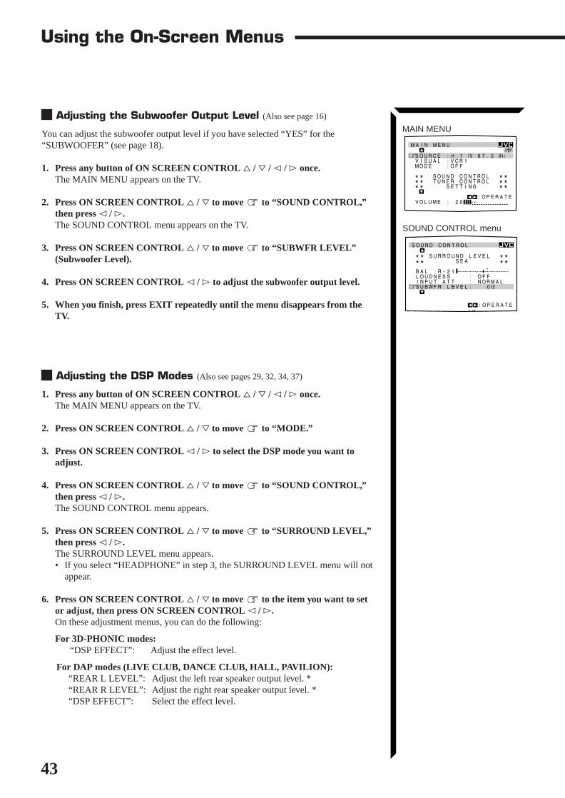
43
MAIN MENU
SOUND CONTROL menu
MAIN MENU
SOURCE :ch 1 FM 87.5 MHz VISUAL :VCR1 MODE :OFF SOUND CONTROL TUNER CONTROL SETTING VOLUME : 20
:OPERATE
******
******
SOUND CONTROL
SURROUND LEVEL SEA BAL.:R-21 LOUDNESS : OFF INPUT ATT : NORMAL SUBWFR LEVEL: 0dB NEXT PAGE
:OPERATE
** **** **
Using the On-Screen Menus
Adjusting the Subwoofer Output Level (Also see page 16)
You can adjust the subwoofer output level if you have selected “YES” for the“SUBWOOFER” (see page 18).
1. Press any button of ON SCREEN CONTROL % / fi / @ / # once.The MAIN MENU appears on the TV.
2. Press ON SCREEN CONTROL % / fi to move to “SOUND CONTROL,”then press @ / #.The SOUND CONTROL menu appears on the TV.
3. Press ON SCREEN CONTROL % / fi to move to “SUBWFR LEVEL”(Subwoofer Level).
4. Press ON SCREEN CONTROL @ / # to adjust the subwoofer output level.
5. When you finish, press EXIT repeatedly until the menu disappears from theTV.
Adjusting the DSP Modes (Also see pages 29, 32, 34, 37)
1. Press any button of ON SCREEN CONTROL % / fi / @ / # once.The MAIN MENU appears on the TV.
2. Press ON SCREEN CONTROL % / fi to move to “MODE.”
3. Press ON SCREEN CONTROL @ / # to select the DSP mode you want toadjust.
4. Press ON SCREEN CONTROL % / fi to move to “SOUND CONTROL,”then press @ / #.The SOUND CONTROL menu appears.
5. Press ON SCREEN CONTROL % / fi to move to “SURROUND LEVEL,”then press @ / #.The SURROUND LEVEL menu appears.• If you select “HEADPHONE” in step 3, the SURROUND LEVEL menu will not
appear.
6. Press ON SCREEN CONTROL % / fi to move to the item you want to setor adjust, then press ON SCREEN CONTROL @ / #.On these adjustment menus, you can do the following:
For 3D-PHONIC modes:“DSP EFFECT”: Adjust the effect level.
For DAP modes (LIVE CLUB, DANCE CLUB, HALL, PAVILION):“REAR L LEVEL”: Adjust the left rear speaker output level. *“REAR R LEVEL”: Adjust the right rear speaker output level. *“DSP EFFECT”: Select the effect level.
EN41_55.RX-1024V[J]/1.PM5 98.5.12, 0:33 PM43

44
For Dolby Surround Pro Logic:“TEST TONE”: Output a test tone.“CENTER LEVEL”: Adjust the center speaker output level. **“REAR L LEVEL”: Adjust the left rear speaker output level. *“REAR R LEVEL”: Adjust the right rear speaker output level. *“CENTER TONE”: Select the center tone level. **
For Dolby Digital:“TEST TONE”: Output a test tone.“CENTER LEVEL”: Adjust the center speaker output level. **“REAR L LEVEL”: Adjust the left rear speaker output level. *“REAR R LEVEL”: Adjust the right rear speaker output level. *“CENTER TONE”: Select the center tone level. **
For Theater Surround and Digital Theater Surround:“TEST TONE”: Output a test tone.“CENTER LEVEL”: Adjust the center speaker output level. **“REAR L LEVEL”: Adjust the left rear speaker output level. *“REAR R LEVEL”: Adjust the right rear speaker output level. *“CENTER TONE”: Select the center tone level. **“DSP EFFECT”: Select the effect level. *
7. When you finish, press EXIT repeatedly until the menu disappears from theTV.
Selecting Your Favorite SEA Mode (Also see page 26)
1. Press any button of ON SCREEN CONTROL % / fi / @ / # once.The MAIN MENU appears on the TV.
2. Press ON SCREEN CONTROL % / fi to move to “SOUND CONTROL,”then press @ / #.The SOUND CONTROL menu appears.
3. Press ON SCREEN CONTROL % / fi to move to “SEA,” then press @ / #.The SEA menu appears.
4. Press ON SCREEN CONTROL % / fi to move to “SEA MODE.”
5. Press ON SCREEN CONTROL @ / # to select the SEA mode you want.
6. When you finish, press EXIT repeatedly until the menu disappears from theTV.
Example:SURROUND LEVEL menufor Theater Surround
SURROUND LEVEL
:OPERATE
TEST TONE : OFF CENTER LEVEL: 0dB REAR L LEVEL: 0dB REAR R LEVEL: 0dB CENTER TONE : FLAT DSP EFFECT : 3
SEA menu
SOUND CONTROL menu
MAIN MENU
MAIN MENU
SOURCE :VCR1 VISUAL :VCR1 MODE :OFF SOUND CONTROL TUNER CONTROL SETTING VOLUME : 20
:ENTER
******
******
SEA
SEA MODE :ROCK SEA ADJUST
:OPERATE
** **
100 10kHz1k
SOUND CONTROL
SURROUND LEVEL SEA BAL.:CNTR LOUDNESS : OFF INPUT ATT : NORMAL SUBWFR LEVEL: 0dB NEXT PAGE
:ENTER
** **** **
Notes:* Not displayed when “REAR
SPK” is set to “NONE” (seepage 19).
** Not displayed when“CENTER SPK” is set to“NONE” (see page 19).
EN41_55.RX-1024V[J]/1.PM5 98.5.12, 0:33 PM44

45
Using the On-Screen Menus
MAIN MENU
SOUND CONTROL menu
SEA menu
SEA ADJUST menu
MAIN MENU
SOURCE :VCR1 VISUAL :VCR1 MODE :OFF SOUND CONTROL TUNER CONTROL SETTING VOLUME : 20
:ENTER
******
******
SOUND CONTROL
SURROUND LEVEL SEA BAL.:CNTR LOUDNESS : OFF INPUT ATT : NORMAL SUBWFR LEVEL: 0dB NEXT PAGE
:ENTER
** **** **
SEA
SEA MODE :ROCK SEA ADJUST
:OPERATE
** **
100 10kHz1k
SETTING 1
SUBWOOFER : NO FRONT SPK : LARGE CENTER SPK : SMALL REAR SPK : LARGE CNTR DELAY : 3msec REAR DELAY : 5msec NEXT PAGE
:ENTER
** **
SETTING 1 menu
SETTING 2 menu
Creating Your Own SEA Mode (Also see page 27)
1. Press any button of ON SCREEN CONTROL % / fi / @ / # once.The MAIN MENU appears on the TV.
2. Press ON SCREEN CONTROL % / fi to move to “SOUND CONTROL,”then press @ / #.The SOUND CONTROL menu appears.
3. Press ON SCREEN CONTROL % / fi to move to “SEA,” then press @ / #.The SEA menu appears.
4. Press ON SCREEN CONTROL % / fi to move to “SEA ADJUST,” thenpress @ / #.The SEA ADJUST menu appears.
5. Press ON SCREEN CONTROL % / fi / @ / # to adjust the SEA mode as youwant.@ / # : Select the frequency ranges.% / fi : Adjust the frequency levels.
6. Press SET to store the setting into the SEA USERMODE.• If you press EXIT, without pressing SET in this step, you can return to the SEA
menu. (The adjustment you have made is active but not stored.)
7. When you finish, press EXIT repeatedly until the menu disappears from theTV.
Basic Settings
1. Press any button of ON SCREEN CONTROL % / fi / @ / # once.The MAIN MENU appears on the TV.
2. Press ON SCREEN CONTROL % / fi to move to “SETTING,” then press@ / #.The SETTING 1 or SETTING 2 menu appears.
3. Press ON SCREEN CONTROL % / fi to the setting item you want to adjust.• To go to the SETTING 2 menu, move to “NEXT PAGE,” then press @ / #.• To go back to the SETTING 1 menu, move to “PREVIOUS PAGE,” then
press @ / #.
On the SETTING 1 and 2 menus, you can do the following:“SUBWOOFER”: Set the subwoofer information (See page 18).“FRONT SPK”: Set the front speaker information (See page 19).“CENTER SPK”: Set the center speaker information (See page 19).“REAR SPK”: Set the rear speaker information (See page 19).“CNTR DELAY”: Adjust the delay time of the center speaker output (See page 20).“REAR DELAY”: Adjust the delay time of the rear speaker output (See page 20).“CROSSOVER”: Set the crossover frequency (See page 20).“LFE ATT.”: Set the low frequency effect attenuator level (See page 21).“COMP.”: Set the dynamic range compression (See page 21).“DIGITAL 1/2/3”: Set the digital input terminal (See page 19).
SEA ADJUSTSEA USERMODE
SET:MEMORY
100 10kHz1k
SETTING 2
CROSSOVER :100Hz LFE ATT. : 0dB COMP. : OFF DIGITAL 1 : DBS DIGITAL 2 : CD DIGITAL 3 : MD PREVIOUS PAGE
:ENTER
** **
EN41_55.RX-1024V[J]/1.PM5 98.5.12, 0:33 PM45

46
4. Press ON SCREEN CONTROL @ / # to set (or adjust) the setting item selectedin step 3.
5. When you finish, press EXIT repeatedly until the menu disappears from theTV.
Operating the Tuner
1. Press any button of ON SCREEN CONTROL % / fi / @ / # once.The MAIN MENU appears on the TV.
2. Press ON SCREEN CONTROL % / fi to move to “TUNER CONTROL,”then press @ / #.The TUNER CONTROL menu appears.
3. Press ON SCREEN CONTROL % / fi to move to the item you want to setor adjust, then press ON SCREEN CONTROL @ / #.On the TUNER CONTROL menu, you can do the following:“PRESET CH”: Select a preset channel station. (See page 24)“BAND”: Select the band. (See page 23)“FREQUENCY”: Tune in a station manually. (See page 23)“FM MODE”: Select the FM reception mode. (See page 24) *“PRESET MEMORY”: See “Storing the Preset Stations” below.
4. When you finish, press EXIT repeatedly until the menu disappears from theTV.
Storing the Preset Stations (Also see page 23)
1. Press any button of ON SCREEN CONTROL % / fi / @ / # once.The MAIN MENU appears on the TV.
2. Press ON SCREEN CONTROL % / fi to move to “TUNER CONTROL,”then press @ / #.The TUNER CONTROL menu appears.
3. Tune into a station on the TUNER CONTROL menu, referring to “Operatingthe Tuner” above.
4. Press ON SCREEN CONTROL % / fi to move to “PRESET MEMORY,”then press @ / #.The PRESET MEMORY menu appears.
5. Press ON SCREEN CONTROL % / fi to move to “PRESET CH.”
6. Press ON SCREEN CONTROL @ / # to select a preset station number youwant.
7. Press SET to store the setting.
8. When you finish, press EXIT repeatedly until the menu disappears from theTV.
MAIN MENU
TUNER CONTROL menu
MAIN MENU
SOURCE :ch 1 FM 87.5 MHz VISUAL :VCR1 MODE :OFF SOUND CONTROL TUNER CONTROL SETTING VOLUME : 20
:ENTER
******
******
TUNER CONTROL
PRESET CH : 1 BAND :FM FREQUENCY : 87.5 MHz FM MODE :AUTO PRESET MEMORY
:OPERATE
** **
PRESET MEMORYFM 87.5 MHz AUTO PRESET CH : CH 1 PRESET NAME: WABC
:OPERATE
:MEMORY
SET
PRESET MEMORY menu
Note:* Not displayed when an AM
station is selected.
EN41_55.RX-1024V[J]/1.PM5 98.5.12, 0:33 PM46

47
Using the On-Screen Menus
Assigning Names to the Preset Stations (Also see page 25)
1. Press any button of ON SCREEN CONTROL % / fi / @ / # once.The MAIN MENU appears on the TV.
2. Press ON SCREEN CONTROL % / fi to move to “TUNER CONTROL,”then press @ / #.The TUNER CONTROL menu appears.
3. Press ON SCREEN CONTROL % / fi to move to “PRESET CH.”
4. Press ON SCREEN CONTROL @ / # to select a preset station.
5. Press ON SCREEN CONTROL % / fi to move to “PRESET MEMORY,”then press @ / #.The PRESET MEMORY menu appears.
6. Press ON SCREEN CONTROL % / fi to move to “PRESET NAME,” thenpress SET.The character entry screen appears.
7. Press ON SCREEN CONTROL % / fi / @ / # to move in front of acharacter you want.You can also select the following:SPACE: To enter space CANCEL: To erase the character
: To go back to the previous character position or go to the next characterposition
8. Press SET to enter the selected character.
9. Repeat steps 7 and 8 to enter up to four characters.
10. Press ON SCREEN CONTROL % / fi / @ / # to move to “PRESETNAME,” then press SET to store the setting.The TUNER CONTROL menu appears again.
11. When you finish, press EXIT repeatedly until the menu disappears from theTV.
MAIN MENU
PRESET MEMORY menu:Character entry screen
PRESET MEMORY
SET:MEMORY
:OPERATE
FM 107.9 MHz AUTO PRESET CH : CH39 PRESET NAME: A B C D E F G H I J K L M N O P Q R S T U V W X Y Z 1 2 3 4 5 6 7 8 9 0 SPACE CANCEL
PRESET MEMORY
SET:MEMORY
:OPERATE
FM 107.9 MHz AUTO PRESET CH : CH39 PRESET NAME: WABC A B C D E F G H I J K L M N O P Q R S T U V W X Y Z 1 2 3 4 5 6 7 8 9 0 SPACE CANCEL
TUNER CONTROL menu
PRESET MEMORY menu
MAIN MENU
SOURCE :ch 1 FM 87.5 MHz VISUAL :VCR1 MODE :OFF SOUND CONTROL TUNER CONTROL SETTING VOLUME : 20
:ENTER
******
******
TUNER CONTROL
PRESET CH :39 BAND :FM FREQUENCY : 87.5 MHz FM MODE :AUTO PRESET MEMORY
:ENTER
** **
PRESET MEMORYFM 87.5 MHz AUTO PRESET CH : CH39 PRESET NAME: WABC
:OPERATE
:MEMORY
SET
EN41_55.RX-1024V[J]/1.PM5 98.5.12, 0:33 PM47

48
COMPU LINK Remote Control SystemThe COMPU LINK remote control system allows you to operate JVC audio components through the remotesensor on the receiver.
To use this remote control system, you need to connect JVC audio components throughthe COMPU LINK-3 (SYNCHRO) jacks (see below) in addition to the connectionsusing cables with RCA pin plugs (see page 8) (and a digital cable if you want — seepage 11).• Make sure that the AC power cords of these components are unplugged before
connection. Plug the AC power cords only after all connections are complete.
This remote control system allows you to use four functions listed below.
Remote Control through the Remote Sensor on the ReceiverYou can control the connected audio components through the remote sensor on thereceiver using this remote control. Aim the remote control directly at the remote sensoron the receiver. For details, see pages 58 and 59.
Automatic Source SelectionWhen you press the play (33333) button on a connected component or on its own remotecontrol, the receiver automatically turns on and changes the source to the component.On the other hand, if you select a new source on the receiver or the remote control, theselected component begins playing immediately.In both cases, the previously selected source continues playing without sound for a fewseconds.
Automatic Power On/Off (Standby): only possible with the COMPULINK-3 connectionBoth the CD player and cassette deck (or MD recorder) turn on and off (standby) alongwith the receiver.When you turn on the receiver, the CD player or cassette deck (or MD recorder) willturn on automatically, depending on which component has been previously selected.When you turn off the receiver, both the CD player and cassette deck (or MD recorder)will turn off (standby).
Synchronized RecordingSynchronized recording means the cassette deck (or MD recorder) starts recording assoon as a CD or a record begins playing.
To use synchronized recording, follow these steps:1. Put a tape in the cassette deck (or an MD in the MD recorder), and a disc in the
CD player (or a record on the turntable).2. Press the record (¶¶¶¶¶) button and the pause (88888) button on the cassette deck (or
MD recorder) at the same time.This puts the cassette deck (or MD recorder) into recording pause.If you do not press the record (¶) button and pause (8) button at the same time, thesynchronized recording feature will not operate.
3. Press the play (33333) button on the CD player or on the turntable.The source changes on the receiver, and as soon as play starts, the cassette deck (orMD recorder) starts recording. When the play ends, the cassette deck (or MDrecorder) enters recording pause, and stops about 4 seconds later.
Notes:• If your audio component has
two COMPU LINK-3(SYNCHRO) jacks, you canuse either one. If it has onlyone COMPU LINK-3(SYNCHRO) jack, connect itso that it is the last item in theseries of components. (Forexample, the turntable or CDplayer in the diagram to theleft.)
• To operate the cassette deckor MD recorder using theCOMPU LINK remote controlsystem, set the source namecorrectly. (See page 17.)
• Refer also to the manualssupplied with your audiocomponents.
Notes:• During synchronized
recording, the selected sourcecannot be changed.
• If your CD player is playing inprogram mode, a 4-secondblank is recorded betweentracks so that the music scanfeature of your cassette deckcan be used on the recordedtape.
• If the power of any componentis shut off during synchronizedrecording, the COMPU LINKremote control system maynot operate properly. In thiscase, you must start againfrom the beginning.
CD player
Turntable
COMPU LINK – 3(SYNCHRO)
Cassette deckor
MD recorder
EN41_55.RX-1024V[J]/1.PM5 98.5.12, 0:33 PM48

49
COMPU LINK – 3(SYNCHRO)
TEXTCOMPU LINK
1(MASTER UNIT)2(SLAVE UNIT)
TEXT COMPU LINK Remote Control SystemThe TEXT COMPU LINK remote control system has been newly developed to deal with the disc informationrecorded in the CD Text* and MDs. Using these information in the discs, you can operate the CD player orMD recorder equipped with the TEXT COMPU LINK remote control system through the receiver.
CONNECTIONS:
To use this remote control system, you need to connect the CD player and/or MDrecorder you want to operate, following the procedures below.
1. If you have already plugged your CD player, MD recorder, and this receiverinto the AC outlets, unplug their AC power cords first.
2. Connect your CD player, MD recorder, and this receiver as follows, through theCOMPU LINK-3 (SYNCHRO) jacks and TEXT COMPU LINK jacks.
1) COMPU LINK-3 (SYNCHRO) jacks: Use the cables with the monaural mini-plugs (not supplied with this receiver)
2) TEXT COMPU LINK jacks: Use the cables with the stereo mini-plugs (notsupplied with this receiver)
IMPORTANT:Set the Master/Slave Selector on the rear to “1(MASTER UNIT).”• “2(SLAVE UNIT)” is just for the serviceman’s use. The TEXT
COMPU LINK remote control system does not function withthe selector set to “2(SLAVE UNIT).”
3. Connect your CD player, MD recorder and this receiver, using the cables withRCA pin plugs (see page 8) (and a digital cable if you want — see page 11).
4. Plug the AC power cords of these components above into the AC outlets.
5. When turning on these components for the first time, turn on the connectedcomponents first, then turn on this receiver.
FUNCTIONS:
This remote control system allows you to use the functions listed below.
Displaying the Disc Information on the TV screenDisc information such as its performer and disc title (and track titles only when a CDText is selected) is shown on the TV screen.
Disc Search: Only for CD PlayerThis remote control system can allow you to search discs by the performer, disc title,and music genre.With this disc search, you can easily find the disc you want to play.
Additional Functions:• If your CD player has the User File function, you can select a disc from the groups.
* A “user file” is a group of the discs you make as you like on the CD player.• If your CD player has the disc memory function, you can input the performer, disc
title, and music genre about these normal audio CDs on the TV screen.
* What is a CD Text?In a CD Text, some informationabout the disc (its disc title,performer, composer, arranger,etc.) is recorded.
Notes:• If your audio component has
two COMPU LINK-3(SYNCHRO) jacks, you canuse either one. If it has onlyone COMPU LINK-3(SYNCHRO) jack, connect itso that it is the last item in theseries of components. (Forexample, the CD player in thediagram to the left.)
• If your audio component hastwo TEXT COMPU LINKjacks, you can use either one.If it has only one TEXTCOMPU LINK jack, connect itso that it is the last item in theseries of components. (Forexample, the CD player in thediagram to the left.)
• Refer also to the manualssupplied with your CD playeror MD recorder.
CD player MD recorder
Note:If you turn on the receiver beforeturning on the other componentsafter connecting components,the TEXT COMPU LINK remotecontrol system does not workcorrectly.If this happens:1. Turn off the all
components includingthis receiver.
2. Turn on the connectedcomponents.
3. Turn on this receiver.
MD recorderCD player
EN41_55.RX-1024V[J]/1.PM5 98.5.12, 0:34 PM49

50
OPERATIONS
To use this remote control system, you need to connect the TV to the MONITOR OUTjack on the rear panel (see page 9), and set the TV’s input mode to the proper position towhich the receiver is connected. Make sure you have connected the CD playeror MD recorder equipped with the TEXT COMPU LINK remote controlsystem. If not, you cannot use the following functions.
Showing the Disc Information on the TV Screen
1. Press any button of ON SCREEN CONTROL % / fi / @ / # once.The MAIN MENU appears on the TV.
2. Press ON SCREEN CONTROL % / fi to move to “SOURCE.”
3. Press ON SCREEN CONTROL @ / # to select “CD” or “MD.”
4. Press ON SCREEN CONTROL % / fi to move to “VISUAL.”
5. Press ON SCREEN CONTROL @ / # to select “OSD,” then press EXIT.The Disc Information screen appears on the TV.
1 Source name: CD or MD2 Select or , then press SET to change the disc.3 Track numbers and track titles.
• The current playing (selected) track is indicated in yellow.• When you move to a track number, you can change the track information by
pressing @ / #. Each time you press the button, the track information alternatesbetween its track title and its performer. (You can also start playing the track bypressing SET.)
4 Select this (move in front), then press SET to go to the DISC SEARCH screen(see page 51).
5 Select this (move in front), then press SET to go to the USER FILE screen (seepage 53).
6 Select this (move in front), then press SET to go to the TITLE INPUT screen (seepage 54).
7 Disc information such as the disc title, performer, and music genre.When this is selected ( in front) , you can change the disc information by pressing@ / #. Each time you press the button, the disc information (see the note) changes.
8 Select or , then press SET to change the track.9 Usable buttons and their functions for the current selection.
Indication here will be changed according to what is currently selected (in front)on the screen.
6. When you finish, press EXIT repeatedly until the MAIN MENU appears onthe TV.
To exit from the MAIN MENU:1) Press ON SCREEN CONTROL % / fi to move to “VISUAL.”2) Press ON SCREEN CONTROL @ / # to select any one other than “OSD,” then
press EXIT.
Notes:• The on-screen display will not
appear about one minute afterthe power is turned on.
• The on-screen display willdisappear in the followingcase:– if no operation is done for
about 10 minutes.– if you do any operation
other than explained in thissection.
• To control the MD recorderusing the TEXT COMPU LINKremote control system, youhave to change the sourcename shown on the displayfrom “TAPE” to “MD.” (Seepage 17.)
• The number of characters toshow the disc informationsuch as the disc title or tracktitle is limited to 32. So if thedisc title, for example, islonger than 32 characters,only the first 32 characters areshown.
• Some special characters suchas accented letters cannot bedisplayed correctly.
Note on 7
The following information willappear on the display:
• Disc title• Performer• Genre• Song writer• Composer• Arranger• Message
Only recorded information willbe shown. If there is no data,“NO DATA” will appear.
Note on 9
For example, the SET button willbe used to start play (PLAY), togo to the next screen (ENTER),and to determine the selection(ENTER).
EN41_55.RX-1024V[J]/1.PM5 98.5.12, 0:34 PM50

51
Searching a Disc (Only for the CD player)
Search a disc by its performer:1. Display the disc information screen by following the procedure on page 50.
2. Press ON SCREEN CONTROL % / fi to move to “SEARCH,” thenpress SET.The DISC SEARCH screen appears on the TV.
3. Press ON SCREEN CONTROL % / fi to move to “PERFORMER”, thenpress SET.The PERFORMER SEARCH screen appears.
4. Press ON SCREEN CONTROL % / fi / @ / # to move in front of thefirst character of the performer you want to search, then press SET.
To correct the incorrect entry, press ON SCREEN CONTROL % / fi tomove in front of the correct character, then press SET.
To erase the incorrect entry, press ON SCREEN CONTROL % / fi to move to“CANCEL,” then press SET.
5. Press SET again.Disc search starts, then the SEARCH RESULT screen, showing the performers,appears.
6. On the SEARCH RESULT screen, you can do the following:
• Changing the indication of the disc information: Press ON SCREEN CONTROL% / fi to move to a searched disc, then press @ / #. Each time you press @ / #,the disc information alternates between its performer and its disc title.
• Going to the Disc Information screen (see page 50): Press ON SCREENCONTROL % / fi to move to a searched disc, then press SET.
• Showing unseen disc information (if more than 5 discs are listed as a result ofthe search): Press ON SCREEN CONTROL % / fi to move to (or ),then press SET.
• Going back to the PERFORMER SEARCH screen: Press EXIT.
Search a disc by its disc title:1. Display the disc information screen by following the procedure on page 50.
2. Press ON SCREEN CONTROL % / fi to move to “SEARCH,” thenpress SET.The DISC SEARCH screen appears on the TV.
3. Press ON SCREEN CONTROL % / fi to move “DISC TITLE”, thenpress SET.The DISC TITLE SEARCH screen appears.
4. Press ON SCREEN CONTROL % / fi / @ / # to move in front of thefirst character of the disc title you want to search, then press SET.
To correct the incorrect entry, press ON SCREEN CONTROL % / fi tomove in front of the correct character, then press SET.
To erase the incorrect entry, press ON SCREEN CONTROL % / fi to move to“CANCEL,” then press SET.
TEXT COMPU LINK Remote Control System
DISC SEARCH screen
PERFORMER SEARCHscreen
SEARCH RESULT screen
DISC SEARCH screen
NoteSymbols such as @, # or $cannot be available for search.
DISC TITLE SEARCH screen
EN41_55.RX-1024V[J]/1.PM5 98.5.12, 0:34 PM51

52
5. Press SET again.Disc search starts, then the SEARCH RESULT screen, showing the disc titles,appears.
6. On the SEARCH RESULT screen, you can do the following:
• Changing the indication of the disc information: Press ON SCREEN CONTROL% / fi to move to a searched disc, then press @ / #. Each time you press @ / #,the disc information alternates between its disc title and its performer.
• Going to the Disc Information screen (see page 50): Press ON SCREENCONTROL % / fi to move to a searched disc, then press SET.
• Showing unseen disc information (if more than 5 discs are listed as a result ofthe search): Press ON SCREEN CONTROL % / fi to move to (or ),then press SET.
• Going back to the DISC TITLE SEARCH screen: Press EXIT.
Search a disc by its genre:1. Display the disc information screen by following the procedure on page 50.
2. Press ON SCREEN CONTROL % / fi to move to “SEARCH,” thenpress SET.The DISC SEARCH screen appears on the TV.
3. Press ON SCREEN CONTROL % / fi to move to “GENRE”, then pressSET.The GENRE SEARCH screen appears.
4. Press ON SCREEN CONTROL % / fi to move to the genre you want tosearch, then press SET.
To show the unseen genres, press ON SCREEN CONTROL % / fi until theyappear.
Disc search starts, then the SEARCH RESULT screen, showing the disc titles,appears.
5. On the SEARCH RESULT screen, you can do the following:
• Changing the indication of the disc information: Press ON SCREEN CONTROL% / fi to move to a searched disc, then press @ / #. Each time you press @ / #,the disc information alternates between its disc title and its performer.
• Going to the Disc Information screen (see page 50): Press ON SCREENCONTROL % / fi to move to a searched disc, then press SET.
• Showing unseen disc information (if more than 5 discs are listed as a result ofthe search): Press ON SCREEN CONTROL % / fi to move to (or ),then press SET.
• Going back to the GENRE SEARCH screen: Press EXIT.
GENRE SEARCH screen
SEARCH RESULT screen
SEARCH RESULT screen
NoteSymbols such as @, # or $cannot be available for search.
EN41_55.RX-1024V[J]/1.PM5 98.5.12, 0:34 PM52

53
TEXT COMPU LINK Remote Control System
Using the User File (Only for the CD Player with the UserFile Function)
You can use the User File function through this receiver.For the User File function, refer to the manual supplied with your CD player.
Using your own User Files:1. Display the disc information screen by following the procedure on page 50.
2. Press ON SCREEN CONTROL % / fi to move to “USER FILE,” thenpress SET.The USER FILE screen appears on the TV.
To show the unseen user files, press ON SCREEN CONTROL % / fi until theyappear.
3. Press ON SCREEN CONTROL % / fi to move to the User File you want,then press SET.The selected User File screen appears on the TV.The disc information shown will be the disc title. (If no disc title information isrecorded for the discs, only the disc numbers will be shown.)
4. On this selected User File screen, you can do the following:
• Changing the indication of the disc information: Press ON SCREENCONTROL % / fi to move to a disc, then press @ / #. Each time you press @/ #, the disc information alternates between its disc title and its performer.
• Starting a disc play: Press ON SCREEN CONTROL % / fi to move to a disc,then press SET.
• Showing unseen disc information (if more than 5 discs are listed): Press ONSCREEN CONTROL % / fi to move to (or ) and press SET.
• Going back to the USER FILE screen: Press EXIT.
USER FILE screen
User File 1 screen
EN41_55.RX-1024V[J]/1.PM5 98.5.12, 0:34 PM53

54
Entering the Disc Information
For the CD Player with the disc memory function:You can use the disc memory function through this receiver.The disc information (its performer, disc title, and its music genre) of normal audio CDswill be stored into the memory built in the CD player.For the disc memory function, refer to the manual supplied with your CD player.• The performer, disc title, and music genre information are usually recorded in a CD
Text. However, if a CD Text has no genre information recorded in the disc itself, youcan input its music genre by yourself.Note: You can enter the TITLE INPUT screens for a CD Text and input its titles.However, you cannot store the titles you have input for a CD Text.
Example: Entering the following information for Disc 1Performer: “MICHEAL”Disc title: “MY FAVORITE”
1. Display the disc information screen by following the procedure on page 50.
2. Press ON SCREEN CONTROL % / fi to move to “TITLE INPUT,” thenpress SET.The TITLE INPUT: PERFORMER screen appears on the TV.
3. Press ON SCREEN CONTROL % / fi / @ / # to move in front of acharacter you want, then press SET to enter the character.• If the current CD is a CD Text, go to step 5 without entering the performer.
To use the lower case letters, press ON SCREEN CONTROL % / fi / @ / # tomove to SHIFT , then press SET.To use the upper case letters again, press ON SCREEN CONTROL % / fi / @ / #to move to SHIFT , then press SET.
4. Repeat step 3 until you finish putting a name (up to 32 characters) to thisUser File.
To insert a space, press ON SCREEN CONTROL % / fi / @ / # to move to SPACE , then press SET.
To correct an incorrect character:1) Press ON SCREEN CONTROL % / fi / @ / # to move to or , then
press SET until the incorrect character is selected.2) Press ON SCREEN CONTROL % / fi / @ / # to move to CANCEL, then
press SET to erase the character.3) Press ON SCREEN CONTROL % / fi / @ / # to move in front of an correct
character, then press SET to enter a correct character.
5. Press ON SCREEN CONTROL % / fi / @ / # to move to “DISC1:MICHEAL (in this example),” then press SET.The TITLE INPUT: DISC TITLE screen appears.
6. Enter the disc title, referring to steps 3 and 4.• If the current CD is a CD Text, go to the next step without entering the disc
title.
TITLE INPUT: PERFORMERscreen
TITLE INPUT: DISC TITLEscreen
Continued to the next page.
EN41_55.RX-1024V[J]/1.PM5 98.5.12, 0:35 PM54

55
7. Press ON SCREEN CONTROL % / fi / @ / # to move to “DISC1: MYFAVORITE (in this example),” then press SET.The TITLE INPUT: DISC 1 GENRE screen appears.
8. Press ON SCREEN CONTROL % / fi to move to the genre you want,then press SET.The Disc Information screen appears again.
To show the unseen genres, press ON SCREEN CONTROL % / fi until theyappear.
For the MD recorder:You can write the disc information (disc title and song titles) into the disc. You can onlywrite the song title for the song currently selected.• If you have the CD-MD combination deck, you can also enter the disc information
(its performer, disc title, and its music genre) of normal audio CDs into the memorybuilt in the CD-MD combination deck. (To do this, follow the procedure on page54.)
1. Display the disc information screen by following the procedure on page 50.
2. Press ON SCREEN CONTROL % / fi to move to “TITLE INPUT,” thenpress SET.The DISC TITLE INPUT screen appears on the TV.
3. Enter the disc title, referring to steps 3 and 4 on page 54.• You can enter up to 32 character for the disc title.
4. Press ON SCREEN CONTROL % / fi / @ / # to move to the disc titleyou have just entered, then press SET.The disc title is stored into the memory, and the SONG TITLE INPUT screen for thecurrently selected song appears.• You can enter a song title for the song currently selected (indicated in yellow on
the TV screen).
5. Enter the song title, referring to steps 3 and 4 on page 54.• You can enter up to 32 character for the song title.
6. Press ON SCREEN CONTROL % / fi / @ / # to move to the song titleyou have just entered, then press SET.The song title is stored into the memory, and the Disc Information screen appearsagain.
TEXT COMPU LINK Remote Control System
TITLE INPUT: DISC 1 GENREscreen
Disc Information screen
DISC TITLE INPUT screen
EN41_55.RX-1024V[J]/1.PM5 98.5.12, 0:35 PM55

56
AV COMPU LINK Remote Control SystemThe AV COMPU LINK remote control system allows you to operate JVC video components (TV, VCR, andDVD player) through the receiver.
CAUTION:
The AV COMPU LINK remotecontrol system cannot controlthe DBS tuner connected to theTV/DBS jacks, and videocomponents connected to theVIDEO and VCR2 jacks on thereceiver.
CONNECTIONS:
To use this remote control system, you need to connect the video components youwant to operate, following the procedures below.1. If you have already plugged your VCR1 (the VCR connected to the VCR 1
jacks), DVD player, TV, and this receiver into the AC outlets, unplug their ACpower cords first.
2. Connect your VCR1, DVD player, TV, and this receiver as follows, using thecables with the monaural mini-plugs (not supplied).
3. Connect the audio input/output jacks on VCR1, DVD player, TV, and thisreceiver using the cables with RCA pin plug (see pages 9 to 10) (and a digitalcable if you want — see page 11).
4. Connect the video input/output jacks on VCR1, DVD player, TV, and thisreceiver as follows, using the cables with RCA pin plug or with S-video plug.
5. Plug the AC power cords of the components into the AC outlets.
6. When turning on the TV for the first time after the AV COMPU LINKconnection, turn the TV volume to the minimum using the TV volume controlon the TV.
Note:When connecting either the VCRor DVD player to this receiver,connect it directly to the receiverusing cable with the monauralmini-plugs.
DVD playerVCR
AVCOMPU LINK
RECEIVER/AMP
AVCOMPU LINK
AVCOMPU LINK
VHS
AVCOMPU LINK
AVCOMPU LINK EX
RECEIVER/AMP
(VCR)EX
DVD
If the AV COMPU LINK terminalon the TV is “AV COMPU LINKEX”
If the AV COMPU LINK terminalon the TV is “RECEIVER/AMP”
IMPORTANT:Connect to the terminal indicated in theillustration.DO NOT connect to the TV terminal.
TV
CASE1: If the components are equipped with the S-videoterminals
CASE3: If only the VCR is equipped with the S-videoterminal.
VIDEOVIDEO S-VIDEO
MONITOROUT
VCR 1
IN(PLAY)
OUT(REC)
DVD
DVD
VHS
VCR
TV
To Video input 2
DVD player
DO NOT use these video terminals.
CASE4: If only the DVD player is equipped with the S-videoterminal.
CASE2: If the components are not equipped with the S-video terminals
VIDEOVIDEO S-VIDEO
MONITOROUT
VCR 1
IN(PLAY)
OUT(REC)
DVD
DVD
S-VHS
VCR
TV
To Video input 1
DVD player
DO NOT use these video terminals.
To Video input 2
VIDEOVIDEO S-VIDEO
MONITOROUT
VCR 1
IN(PLAY)
OUT(REC)
DVD
DVD
S-VHS
VCRTo Video input 1
DVD player
DO NOT use these video terminals.
VIDEOVIDEO S-VIDEO
MONITOROUT
VCR 1
IN(PLAY)
OUT(REC)
DVD
DVD
VHS
VCR
TV
To Video input 2
DVD player
DO NOT use these video terminals.
To Video input 1
EN56_70.RX-1024V[J]/1.PM5 98.5.12, 0:44 PM56

57
Note:Refer also to the manualssupplied with your videocomponents.
FUNCTIONS:
This remote control system allows you to use five functions listed below.
Remote Control of DVD Player, VCR, and TV Using This RemoteControlFor the DVD player and the VCR:• Aim the remote control directly at the remote sensor on the each component.For the TV having AV COMPU LINK terminal “RECEIVER/AMP”:• Aim the remote control directly at the remote sensor on the receiver when
operating the TV.For the TV having AV COMPU LINK terminal “AV COMPU LINK EX”:• Aim the remote control directly at the remote sensor on the TV when operating the
TV.
One-Touch Video PlaySimply by inserting a video cassette without its safety tab into the VCR1 (the VCRconnected to the VCR1 jacks), you can enjoy the video playback without setting otherswitches manually.The receiver automatically turns on and changes the source to “VCR1.”The TV automatically turns on and changes the input mode to the position so that youcan view the playback picture.When you insert a video cassette with its safety tab, press the play (33333) button on theVCR1 or on the remote control. So, you can get the same result.
One-Touch DVD PlaySimply by starting playback on the DVD player, you can enjoy the DVD playbackwithout setting other switches manually.The receiver automatically turns on and changes the source to “DVD”— “DVD” isautomatically selected.The TV automatically turns on and changes the input mode to the position so that youcan view the playback picture.
Automatic Selection of TV’s Input Mode• When you select “TV SOUND” as the source to play on the receiver, the TV
automatically changes the input mode to the TV tuner so that you can watch TV.• When you select “VCR2,” as the source to play on the receiver, the TV
automatically changes the input mode to the Video Input 2 so that you can watch theplayback picture.
• When you select “DVD,” “VCR1,” “VIDEO” or “DBS” as the source to play on thereceiver, the TV automatically changes the input mode to the appropriate position(either Video Input 1 or Video Input 2) so that you can view the playback picture.
Automatic Power On/Off (Standby)The TV, VCR1 (the VCR connected to the VCR1 jacks), and DVD player turn on andoff along with the receiver.• When you turn on the receiver;
• If the previously selected source is “VCR1,” the TV and VCR1 will turn onautomatically.
• If the previously selected source is “VIDEO” or “TV SOUND,” only the TVwill turn on automatically.
• If the previously selected source is “DVD,” the TV and DVD player will turn onautomatically.
When you turn off the receiver, the TV, VCR1 and the DVD player will turn off.
Note:When you select “TV SOUND”as the source on the receiver,you cannot see the menu on theTV screen since the AV COMPULINK remote control systemautomatically changes the TV’sinput mode to the TV tuner.If you do not mind stoppinglistening to the TV sounds, youcan then show the on-screendisplays after changing the TV’sinput mode to the appropriateposition (either Video Input 1 orVideo Input 2) the receiver isconnected to.
Note:If you turn off the receiver whilerecording on the VCR1, theVCR1 will not turn off, butcontinue recording.
EN56_70.RX-1024V[J]/1.PM5 98.5.12, 0:44 PM57

58
IMPORTANT:To operate JVC’s audio components using this remote control:• You need to connect JVC audio components through the COMPU LINK-3
(SYNCHRO) jacks (see page 48) in addition to the connections using cableswith RCA pin plugs (see page 8) or using digital cables (see page 11).
• Aim the remote control directly at the remote sensor on the receiver.
Tuner
After pressing FM or AM (with the remote control modeselector set to “AUDIO/TV/VCR”), you can perform thefollowing operations:FM: Selects an FM broadcast.AM: Selects an AM broadcast.1 — 10, +10: Selects a preset channel number directly.
For channel number 5, press 5. Forchannel number 15, press +10, then 5.For channel number 20, press +10, then10.
TUNING UP/TUNING DOWN:Tunes into stations.
FM MODE/MUTE: Changes the FM reception mode.
Sound control section (Amplifier)
You can always perform the following operations (with theremote control mode selector set to “AUDIO/TV/VCR”):SURROUND MODE: Changes the DSP modes.
After pressing SOUND (with the remote control mode selectorset to “AUDIO/TV/VCR”), you can perform the followingoperations:SEA MODE: Changes the SEA modes.SUBWOOFER +/–: Adjusts the subwoofer output level.CNTR +/–: Adjusts the center speaker output
level.REAR•L +/–: Adjusts the left rear speaker output
level.REAR•R +/–: Adjusts the right rear speaker output level.EFFECT: Selects the effect level.TEST: Turns on or off the test tone output.CNTR TONE: Selects the center tone.
CD player
After pressing CD (with the remote control mode selector set to “AUDIO/TV/VCR”),you can perform the following operations on a CD player:PLAY: Starts playing.44444: Returns to the beginning of the current (or previous) track.¢¢¢¢¢: Skips to the beginning of the next track.STOP: Stops playing.PAUSE: Pauses playing. To release it, press PLAY.1 — 10, +10: Selects a track number directly.
For track number 5, press 5. For track number 15, press +10, then 5. Fortrack number 20, press +10, then 10. For track number 30, press +10,+10, then 10.
Notes:• If you use the buttons on the
front panel or the menufunction to choose a source,the remote control will notoperate that source. Tooperate a source with theremote control, the sourcemust be selected usingbuttons on the remote control.
• Check to see if its remotecontrol mode selector is set tothe correct position. Tooperate audio system, TVs,and VCRs, set it to “AUDIO/TV/VCR.”
• Refer also to the manualssupplied with yourcomponents.
Note:After adjusting sounds, pressthe corresponding sourceselecting button or DISC tooperate your target source byusing 10 keys; otherwise, 10keys cannot be used foroperating your target source.
Operating JVC’s Audio/Video ComponentsYou can operate JVC’s audio and video components with this receiver’s remote control, since controlsignals for JVC components are preset in the remote control.
TV/CATV/DBS VCR 1
POWER
VCR 1 VCR 2 VIDEO
CD TAPE/MD PHONO TV/DBS
AM
MODE
SURROUND CNTR TONE CNTR– +
DIGITAL/ANALOG
INPUT
CHANNEL– +
VOLUME– +
DISC
MUTE
+10100+
10
FM
1
SLEEP
POWER POWER
AUDIO
2 3
TEST REAR · L
AUDIO/TV/VCR
CATV
DBS
REAR · R
– +
4 5 6
EFFECT
SEA MODE
RETURN FM MODE/MUTE
– +
SUBWOOFER– +
8
0
9
ENTER
MENU
MENU
SET EXIT
VCR1
/REW PLAY
TAPE
ON SCREEN CONTROL
CONTROL
LIGHT
FF/
DOWN TUNING UP
TV/VIDEO
REC
STOP PAUSE
RM-SR1024U REMOTE CONTROL
SOUND
DVD
7/P
EN56_70.RX-1024V[J]/1.PM5 98.5.12, 0:44 PM58

59
CD player-changer
After pressing DISC (with the remote control mode selector setto “AUDIO/TV/VCR”), you can perform the followingoperations on the CD player-changer:PLAY: Starts playing.44444: Returns to the beginning of the current (or
previous) track.¢¢¢¢¢: Skips to the beginning of the next track.STOP: Stops playing.PAUSE: Pauses playing. To release it, press the PLAY
button.1 — 6, 7/P: Select the number of a disc installed in a CD
player-changer.
After pressing CD (with the remote control mode selector set to“AUDIO/TV/VCR”), you can perform the following operationson the CD player-changer:1 — 10, +10: Selects a track number directly.
For track number 5, press 5. For track number15, press +10, then 5. For track number 20,press +10, then 10. For track number 30, press+10, +10, then 10.
Turntable
After pressing PHONO (with the remote control mode selectorset to “AUDIO/TV/VCR”), you can perform the followingoperations on the turntable:PLAY: Starts playing.STOP: Stops playing.
Cassette deck
After pressing TAPE/MD or TAPE CONTROL (with theremote control mode selector set to “AUDIO/TV/VCR”), youcan perform the following operations on the cassette deck:PLAY: Starts playing.REW: Fast winds the tape from right to left.FF: Fast winds the tape from left to right.STOP: Stops operations.PAUSE: Pauses playing or recording temporarily. To release it, press the PLAY button.REC ¶¶¶¶¶: Press this button with the PLAY button to start recording.
Press this button with the PAUSE button to enter recording pause.
MD recorder
After pressing TAPE/MD or TAPE CONTROL (with the remote control mode selectorset to “AUDIO/TV/VCR”), you can perform the following operations on the MDrecorder:PLAY: Starts playing.44444: Returns to the beginning of the current (or previous) track.¢¢¢¢¢: Skips to the beginning of the next track.STOP: Stops playing.PAUSE: Pauses playing. To release it, press the PLAY button.REC ¶¶¶¶¶: Press this button with the PLAY button to start recording.
Press this button with the PAUSE button to enter recording pause.
Operating JVC’s Audio/Video Components
Notes:• To operate the cassette deck
or MD recorder using theCOMPU LINK remote controlsystem, set the source namecorrectly. (See page 17.)
• You can use either the TAPE/MD button or the TAPECONTROL button to activatethe buttons listed to the left. Ifyou press TAPE/MD, theplaying source also changes.On the other hand, if youpress TAPE CONTROL, theplaying source does notchange.
TV/CATV/DBS VCR 1
POWER
VCR 1 VCR 2 VIDEO
CD TAPE/MD PHONO TV/DBS
AM
MODE
SURROUND CNTR TONE CNTR– +
DIGITAL/ANALOG
INPUT
CHANNEL– +
VOLUME– +
DISC
MUTE
+10100+
10
FM
1
SLEEP
POWER POWER
AUDIO
2 3
TEST REAR · L
AUDIO/TV/VCR
CATV
DBS
REAR · R
– +
4 5 6
EFFECT
SEA MODE
RETURN FM MODE/MUTE
– +
SUBWOOFER– +
8
0
9
ENTER
MENU
MENU
SET EXIT
VCR1
/REW PLAY
TAPE
ON SCREEN CONTROL
CONTROL
LIGHT
FF/
DOWN TUNING UP
TV/VIDEO
REC
STOP PAUSE
RM-SR1024U REMOTE CONTROL
SOUND
DVD
7/P
EN56_70.RX-1024V[J]/1.PM5 98.5.12, 0:44 PM59

60
IMPORTANT:To operate JVC’s video components using this remote control:• You need to connect JVC video components through the AV COMPU LINK
jacks (see page 56) in addition to the connections using cables with RCA pinplugs (see pages 9 to 10) or using a digital cable (see page 11).
• When using the remote control:– For the DVD player and the VCR: Aim the remote control directly at the
remote sensor on the each component.– For the TV having AV COMPU LINK terminal “RECEIVER/AMP”: Aim the
remote control directly at the remote sensor on the receiver when operating theTV.
– For the TV having AV COMPU LINK terminal “AV COMPU LINK EX”: Aimthe remote control directly at the remote sensor on the TV when operating theTV.
VCR1 (the VCR connected to the VCR1 jacks)
You can always perform the following operations (with theremote control mode selector set to “AUDIO/TV/VCR”):VCR1 POWER: Turns on or off the VCR1.
After pressing VCR1 or VCR1 CONTROL (with the remotecontrol mode selector set to “AUDIO/TV/VCR”), you canperform the following operations on the VCR:PLAY: Starts playing.REW: Rewinds a tape.FF: Fast winds a tape.STOP: Stops operations.PAUSE: Pauses playing or recording temporarily. To
release it, press the PLAY button.REC ¶¶¶¶¶: Press this button with the PLAY button to
start recording.Press this button with the PAUSE button toenter recording pause.
CHANNEL +/–: Changes the channels on the VCR.1 – 9, 0: Selects the channels on the VCR.
For channel 5, press 5.For channel 10, press 1, then 0.
DVD player
After pressing DVD (with the remote control mode selector setto “AUDIO/TV/VCR”), you can perform the followingoperations on a DVD player:PLAY: Starts playing.44444: Returns to the beginning of the current (or
previous) track.¢¢¢¢¢: Skips to the beginning of the next track.STOP: Stops playing.PAUSE: Stops playing temporarily. To release it, press the
PLAY button.
After pressing DVD (with theremote control mode selectorset to the “AUDIO/TV/VCR”position), these buttons canbe used for the DVD menuoperations.
Note:For detailed menu operations,refer to the instructionssupplied with the discs or theDVD player.
Notes:• Some JVC VCRs can accept
two types of the controlsignals – code “A” and “B.”Before using this remotecontrol, make sure that theremote control code of theVCR1 is set to code “A.”
• You can use either the VCR1button or the VCR1CONTROL button to activatethe buttons listed to the left. Ifyou press VCR1, the playingsource also changes. On theother hand, if you press VCR1CONTROL, the playing sourcedoes not change.
TV/CATV/DBS VCR 1
POWER
VCR 1 VCR 2 VIDEO
CD TAPE/MD PHONO TV/DBS
AM
MODE
SURROUND CNTR TONE CNTR– +
DIGITAL/ANALOG
INPUT
CHANNEL– +
VOLUME– +
DISC
MUTE
+10100+
10
FM
1
SLEEP
POWER POWER
AUDIO
2 3
TEST REAR · L
AUDIO/TV/VCR
CATV
DBS
REAR · R
– +
4 5 6
EFFECT
SEA MODE
RETURN FM MODE/MUTE
– +
SUBWOOFER– +
8
0
9
ENTER
MENU
MENU
SET EXIT
VCR1
/REW PLAY
TAPE
ON SCREEN CONTROL
CONTROL
LIGHT
FF/
DOWN TUNING UP
TV/VIDEO
REC
STOP PAUSE
RM-SR1024U REMOTE CONTROL
SOUND
DVD
7/P
CNTR– +
2 3
TEST REAR · L
REAR · R
– +
4 5 6
– +
8
ENTER
MENU
EN56_70.RX-1024V[J]/1.PM5 98.5.12, 0:44 PM60

61
TV
You can always perform the following operations (with theremote control mode selector set to “AUDIO/TV/VCR”):TV/CATV/DBS POWER: Turns on or off the TV.TV/VIDEO: Sets the input mode (either TV or
VIDEO).
After pressing TV/DBS (with the remote control mode selectorset to “AUDIO/TV/VCR”), you can perform the followingoperations on a TV:CHANNEL +/–: Changes the channels.1 – 9, 0, 100+: Selects the channels.RETURN: Alternates between the previously
selected channel and the current channel.
Operating JVC’s Audio/Video Components
TV/CATV/DBS VCR 1
POWER
VCR 1 VCR 2 VIDEO
CD TAPE/MD PHONO TV/DBS
AM
MODE
SURROUND CNTR TONE CNTR– +
DIGITAL/ANALOG
INPUT
CHANNEL– +
VOLUME– +
DISC
MUTE
+10100+
10
FM
1
SLEEP
POWER POWER
AUDIO
2 3
TEST REAR · L
AUDIO/TV/VCR
CATV
DBS
REAR · R
– +
4 5 6
EFFECT
SEA MODE
RETURN FM MODE/MUTE
– +
SUBWOOFER– +
8
0
9
ENTER
MENU
MENU
SET EXIT
VCR1
/REW PLAY
TAPE
ON SCREEN CONTROL
CONTROL
LIGHT
FF/
DOWN TUNING UP
TV/VIDEO
REC
STOP PAUSE
RM-SR1024U REMOTE CONTROL
SOUND
DVD
7/P
Note:When you turn off the receiverwith the TV kept turned on, thereceiver will turn on soon again.To prevent this from happening,make sure that you turn off theTV before turning off thereceiver.
When the TV is connected to the TV SOUND/DBS jacks on the rear:The receiver automatically turns on and select “TV SOUND” as the source about 5seconds after you turn on the TV. (If you change the source name from “TVSOUND” to “DBS,” the receiver will not turn on along with the TV. See page 17)
EN56_70.RX-1024V[J]/1.PM5 98.5.12, 0:44 PM61

62
This remote control supplied with the receiver can transmit control signals for othermanufacturers’ VCRs, TVs, CATV converters and DBS tuners. By changing thetransmittable signals from preset ones to the other manufacturers’, you can operate theother manufacturer’s components using this remote control.
When operating the other manufacturers’ components, refer also to the manualssupplied with them.To operate these components with the remote control, first you need to set themanufacturer’s code each for the VCR, TV, CATV converter, and DBS tuner.
IMPORTANT:When using the Remote Control, check to see if its remote controlmode selector is set to the correct position:To operate an audio system, TV, and VCR, set it to “AUDIO/TV/VCR.”To operate a CATV converter, set it to “CATV.”To operate a DBS tuner, set it to “DBS.”
To change the transmittable signals for operating anothermanufacturer’s TV1. Set the remote control mode selector to “AUDIO/TV/
VCR.”
2. Press and hold TV/CATV/DBS POWER.
3. Press TV/DBS.
4. Enter the manufacturer’s code (three digits) usingbuttons 1 – 9, and 0.See the lists on page 65 to find the code.
5. Release TV/CATV/DBS POWER.The following buttons can be used for operating the TV(with the remote control mode selector set to “AUDIO/TV/VCR”):TV/CATV/DBS POWER: Turns on and off TV.TV/VIDEO: Sets the input mode (either TV or
VIDEO).
After pressing TV/DBS (with the remote control modeselector set to “AUDIO/TV/VCR”), you can perform thefollowing operations on the TV:CHANNEL +/–: Changes the channels.1 – 10, 0, 100+(+10):Selects the TV channels.
100+(+10) button will function as the ENTER button if yourTV requires pressing ENTER after selecting a channelnumber.
6. Try to operate your TV by pressing TV/CATV/DBS POWER.When your TV turns on or off, you have entered the correct code.
7. If there are more than one code listed for your brand of TV, try each one untilthe correct one is entered.
Note:Refer also to the manualsupplied with your TV.
Operating Other Manufactures’ Components
TV/CATV/DBS VCR 1
POWER
VCR 1 VCR 2 VIDEO
CD TAPE/MD PHONO TV/DBS
AM
MODE
SURROUND CNTR TONE CNTR– +
DIGITAL/ANALOG
INPUT
CHANNEL– +
VOLUME– +
DISC
MUTE
+10100+
FM SLEEP
POWER POWER
AUDIO
TEST REAR · L
AUDIO/TV/VCR
CATV
DBS
REAR · R
– +
EFFECT
SEA MODE
RETURN FM MODE/MUTE
– +
SUBWOOFER– +
ENTER
MENU
MENU
SET EXIT
VCR1
/REW PLAY
TAPE
ON SCREEN CONTROL
CONTROL
LIGHT
FF/
DOWN TUNING UP
REC
STOP PAUSE
RM-SR1024U REMOTE CONTROL
SOUND
DVD
TV/VIDEO
9
010
4 5 6
321
7/P 8
When the TV is connected to the TV SOUND/DBS jacks on the rear:The receiver automatically turns on and select “TV SOUND” as the source about 5seconds after you turn on the TV. (If you change the source name from “TVSOUND” to “DBS,” the receiver will not turn on along with the TV. See page 17)
AUDIO/TV/VCR
CATV
DBS
Note:When you turn off the receiverwith the TV kept turned on, thereceiver will turn on soon again.To prevent this from happening,make sure that you turn off theTV before turning off thereceiver.
EN56_70.RX-1024V[J]/1.PM5 98.5.12, 0:44 PM62

63
To change the transmittable signals for operating a CATVconverter or DBS tuner1. For the CATV converter:
Set the remote control mode selector to “CATV.”
For the DBS tuner:Set the remote control mode selector to “DBS.”
2. Press and hold TV/CATV/DBS POWER.
3. Press TV/DBS.
4. Enter the manufacturer’s code (three digits) usingbuttons 1 – 9, and 0.See the lists on page 66 to find the code.
5. Release TV/CATV/DBS POWER.After setting the remote control mode selector to “CATV”or “DBS,” you can perform the following operations on theCATV converter or on the DBS tuner:TV/CATV/DBS POWER: Turns on and off the CATV
converter or DBS tuner.CHANNEL +/–: Changes the channels.1 – 10, 0, 100+(+10): Selects the channels.
100+(+10) button will functionas the ENTER button if yourCATV converter or DBS tunerrequires pressing ENTER afterselecting a channel number.
6. Try to operate your CATV converter or DBS tuner bypressing TV/CATV/DBS POWER.When your CATV converter or DBS tuner turns on or off, you have entered thecorrect code.
7. If there are more than one code listed for your brand of CATV converter orDBS tuner, try each one until the correct one is entered.
Note:Refer also to the manualsupplied with your CATVconverter or DBS tuner.
Operating Other Manufactures’ Components
TV/CATV/DBS VCR 1
POWER
VCR 1 VCR 2 VIDEO
CD TAPE/MD PHONO TV/DBS
AM
MODE
SURROUND CNTR TONE CNTR– +
DIGITAL/ANALOG
INPUT
CHANNEL– +
VOLUME– +
DISC
MUTE
100+
FM SLEEP
POWER POWER
AUDIO
TEST REAR · L
AUDIO/TV/VCR
CATV
DBS
REAR · R
– +
EFFECT
SEA MODE
RETURN FM MODE/MUTE
– +
SUBWOOFER– +
ENTER
MENU
MENU
SET EXIT
VCR1
/REW PLAY
TAPE
ON SCREEN CONTROL
CONTROL
LIGHT
FF/
DOWN TUNING UP
REC
STOP PAUSE
RM-SR1024U REMOTE CONTROL
SOUND
DVD
TV/VIDEO
1 2 3
4 5 6
7/P 8 9
10 0 +10
EN56_70.RX-1024V[J]/1.PM5 98.5.12, 0:44 PM63

64
To change the transmittable signals for operating anothermanufacturer’s VCR1. Set the remote control mode selector to “AUDIO/TV/
VCR.”
2. Press and hold VCR1 POWER.
3. Press VCR1.
4. Enter the manufacturer’s code (three digits) usingbuttons 1 – 9, and 0.See the lists on pages 66 and 67 to find the code.
5. Release VCR1 POWER.The following buttons can be used for operating the VCR(with the remote control mode selector set to “AUDIO/TV/VCR”):VCR1 POWER: Turns on and off VCR.
After pressing VCR1 or VCR1 CONTROL (with the remotecontrol mode selector set to “AUDIO/TV/VCR”), you canperform the following operations on the VCR:CHANNEL +/–: Changes the channels on the VCR.1 – 10, 0, 100+(+10):Selects the channels on the VCR.
100+(+10) button will function asthe ENTER button if your VCRrequires pressing ENTER afterselecting a channel number.
PLAY: Starts playback.STOP: Stops operations.PAUSE: Pauses.REW: Rewinds a tape.FF: Fast winds a tape.REC ¶¶¶¶¶: Starts recording or enters recording pause.
6. Try to operate your VCR by pressing VCR1 POWER.When your VCR turns on or off, you have entered the correct code.
7. If there are more than one code listed for your brand of VCR, try each one untilthe correct one is entered.
Notes:• You can use either the VCR1
button or the VCR1 CONTROLbutton to activate the buttonslisted to the left. If you pressVCR1, the playing source alsochanges. On the other hand, ifyou press VCR1 CONTROL,the playing source does notchange.
• Refer also to the manualsupplied with your VCR.
TV/CATV/DBS VCR 1
POWER
VCR 1 VCR 2 VIDEO
CD TAPE/MD PHONO TV/DBS
AM
MODE
SURROUND CNTR TONE CNTR– +
DIGITAL/ANALOG
INPUT
CHANNEL– +
VOLUME– +
DISC
MUTE
100+
FM SLEEP
POWER POWER
AUDIO
TEST REAR · L
AUDIO/TV/VCR
CATV
DBS
REAR · R
– +
EFFECT
SEA MODE
RETURN FM MODE/MUTE
– +
SUBWOOFER– +
ENTER
MENU
MENU
SET EXIT
TAPE
ON SCREEN CONTROL
CONTROL
LIGHT
DOWN TUNING UP
REC
RM-SR1024U REMOTE CONTROL
SOUND
DVD
TV/VIDEO
VCR1
/REW PLAY FF/
STOP PAUSE
7/P
10 0
8 9
+10
654
1 2 3
EN56_70.RX-1024V[J]/1.PM5 98.5.12, 0:44 PM64

65
Manufacturers’ codes for TV
Admiral 093Aiko 092Akai 030Alaron 179Anam 180Anam National 055AOC 019, 030Audiovox 180Belcor 019Bell & Howell 016, 154Bradford 180Brockwood 019Candle 030, 056Carnivale 030Carver 054Celebrity 000Citizen 030, 039, 056, 060, 092, 280Concerto 056Contec 180Craig 180Crown 039, 180Curtis Mathes 030, 039, 060, 154CXC 180Daewoo 019, 039, 092, 451Daytron 019Denon 145Dumont 017, 019Electroband 000Emerson 019, 039, 154, 178, 179, 180, 236, 280,
282, 463Envision 030Fisher 154, 159Fujitsu 179Funai 171, 179, 180Futuretech 180GE 021, 047, 051, 055, 178, 282, 451Gibralter 017, 019, 030GoldStar 019, 030, 039, 178Grunpy 179, 180Hallmark 178Harvard 180Hitachi 056, 145, 151Infinity 054JBL 054JCB 000JVC 053, 069, 160, 169KEC 180Kenwood 019, 030KTV 030, 039, 180, 280Logik 016Luxman 056LXI 047, 054, 154, 156, 178Magnavox 030, 054, 187Majestic 016Marantz 030, 054Matsushita 250Megatron 145, 178Memorex 016, 056, 150, 154, 178MGA 019, 030, 150, 178Midland 017, 039, 047, 051Minutz 021Mitsubishi 019, 093, 150, 178Motorola 055, 093MTC 019, 030, 056, 060Multitech 180NAD 156, 166, 178NEC 019, 030, 056Nikko 030, 092, 178
Noshi 018NTC 092Onwa 180Optimus 154, 166, 250Optonica 093, 165Orion 236Panasonic 051, 055, 250Penney 018, 019, 021, 030, 039, 047, 051, 060,
156, 178Philco 019, 030, 054Philips 054Pilot 019, 030, 039Pioneer 166Portland 019, 039, 092Prism 051Proscan 047Proton 178Pulsar 017, 019Quasar 051, 055, 165, 250Radio Shack 019, 030, 039, 047, 056, 154, 165, 178,
180RCA 018, 019, 047, 090Realistic 019, 030, 039, 056, 154, 165, 178, 180Runco 017, 030Sampo 030, 039Samsung 019, 030, 039, 056, 060, 178Samsux 039Sansei 451Sanyo 154, 159Scimitsu 019Scotch 178Scott 019, 178, 179, 180, 236Sears 047, 054, 056, 154, 156, 159, 171, 178,
179Sharp 039, 093, 165Shogun 019Signature 016Simpson 187Sony 000Soundesign 178, 179, 180Squareview 171SSS 019, 180Starlite 180Supreme 000Sylvania 030, 054Symphonic 171Tandy 093Tatung 055Technics 051, 250Technol Ace 179Techwood 051, 056Teknika 016, 019, 039, 054, 056, 060, 092, 150,
179, 180TMK 056, 178Telefunken 056Toshiba 060, 154, 156Totevision 039Vector Research 030Victor 053Vidikron 054Vidtech 019, 178Wards 016, 019, 021, 030, 054, 056, 165, 178,
179Yamaha 019, 030Zenith 016, 017
Operating Other Manufactures’ Components
EN56_70.RX-1024V[J]/1.PM5 98.5.12, 0:44 PM65

66
Manufacturers’ codes for CATV converters
ABC 003, 007, 008, 011, 013, 014, 017Allegro 153Archer 153Century 153Citizen 153Comtronics 040Contec 019Everquest 015, 040Focus 400Garrard 153Gemini 015General Instrument 011, 276GoldStar 040, 144Hamlin 009, 020, 259, 273Hitachi 011Hytex 007Jasco 153Jerrold 003, 011, 012, 014, 015, 276Memorex 000Oak 007, 019Optimus 021Panasonic 000, 021Paragon 000Philips 153Pioneer 144Popular Mechanics 400Pulsar 000Radio Shack 015RCA 021Recoton 400Regal 020, 259, 273Rembrandt 011Runco 000Samsung 040, 144Scientific Atlanta 008, 017, 277Signal 015, 040Signature 011SL Marx 040Sprucer 021Starcom 003, 015Stargate 015, 040Starquest 015Teleview 040Tocom 012, 013Toshiba 000Tusa 015Unika 153United Artists 007United Cable 003Universal 153Zenith 000Zentek 400
Manufacturers’ codes for DBS tuner
AlphaStar 772Echostar 775HTS 775Hitachi 819Hughes Network Systems 749Jerrold 627Panasonic 701Primestar 627RCA 566Sony 639
Manufacturers’ codes for VCR
Admiral 048Adventura 000Aiko 278Aiwa 000, 037Akai 041American High 035Asha 240Audiovox 037Beaumark 240Bell & Howell 104Broksonic 121, 184, 211Calix 037Canon 035Capehart 020Carver 081CCE 072, 278Citizen 037, 278Colt 072Craig 037, 047, 072, 240Curtis Mathes 035, 041, 060Cybernex 240Daewoo 020, 045, 278Daytron 020Denon 042Dynatech 000Electrohome 037Electrophonic 037Emerex 032Emerson 000, 002, 037, 043, 121, 184, 209, 211,
212, 278, 479Fisher 047, 054, 104Fuji 033, 035Funai 000Garrard 000GE 035, 060GoldStar 037, 038Gradiente 000Harley Davidson 000Harman/Kardon 038Harwood 072Headquarter 046HI-Q 047Hitachi 041, 042Jensen 041JVC 008, 041, 067KEC 037, 278Kenwood 038, 041, 067KLH 072Kodak 035, 037Lloyd’s 000Logik 072LXI 037Magnavox 035, 039, 081, 149Magnin 240Marantz 035, 081Marta 037Matsushita 035, 162MEI 035Memorex 000, 035, 037, 039, 046, 047, 048, 104,
240MGA 043MGN Technology 240Minolta 042Mitsubishi 043, 067Motorola 035, 048MTC 000, 240Multitech 000, 072
EN56_70.RX-1024V[J]/1.PM5 98.5.12, 0:44 PM66

67
NEC 038, 041, 067, 104Nikko 037Nikon 034Noblex 240Olympus 035Optimus 037, 048, 104, 162Orion 479Panasonic 035, 162, 225Penney 035, 037, 038, 042, 054, 240Pentax 042Philco 035Philips 035, 081Pilot 037Pioneer 067Portland 020Profitronic 240Protec 072Pulsar 039Quarter 046Quartz 046Quasar 035, 162Radio Shack 000, 037Radix 037Randex 037RCA 042, 060, 149Realistic 000, 035, 037, 046, 047, 048, 104Ricoh 034Runco 039Samsung 045, 240Sanky 039, 048Sansui 041, 067Sanyo 046, 047, 104, 240Scott 043, 045, 121, 184, 211, 212Sears 035, 037, 042, 046, 047, 054, 104Sharp 048Shintom 072Shogun 240Singer 072Sony 032, 033, 034, 035STS 042Sylvania 000, 035, 043, 081Symphonic 000Tatung 041Teac 000, 041Technics 035, 162Teknika 000, 035, 037TMK 240Toshiba 043, 045, 212Totevision 037, 240Unitech 240Vector 045Vector Research 038Video Concepts 045Videosonic 240Wards 000, 035, 042, 047, 048, 060, 072, 081,
149, 212, 240XR-1000 000, 035, 072Yamaha 038Zenith 033, 034, 039
Operating Other Manufactures’ Components
Manufacturers’ codes listed on page 65 to 67 are subject tochange without notice. If they are changed, this remotecontrol cannot operate the equipment.
EN56_70.RX-1024V[J]/1.PM5 98.5.12, 0:44 PM67

68
TroubleshootingUse this chart to help you solve daily operational problems. If there is any problem you cannot solve,contact your JVC service center.
PROBLEM
The display does not light up.
No sound from speakers.
Sound from one speaker only.
Continuous hiss or buzzing during FMreception.
Occasional cracking noise during FMreception.
Howling during record playing.
“OVERLOAD” starts flashing on thedisplay.
Remote control does not work.
SOLUTION
Plug the power cord into an ACoutlet.
Check speaker wiring andreconnect if necessary.
Press SPEAKERS 1 and 2 correctly.
Select the correct source.
Press MUTE to cancel the mute.
Check speaker wiring and reconnectif necessary.
Adjust the balance properly (seepage 18).
Connect an outside FM antenna orcontact your dealer.
Select a new station.
Check with your dealer to be sureyou have the correct antenna.
Check connections.
Move the antenna farther fromautomobile traffic.
Move speakers away from theturntable.
Rotate the MASTER VOLUMEcontrol counterclockwise three orfour times then press POWER onthe front panel.If “OVERLOAD” does notdisappear, unplug the AC powercord, then plug it back again.
Press POWER on the front panelthen check the speaker wiring.If “OVERLOAD” does notdisappear, unplug the AC powercord, then plug it back again.If speaker wiring is not short-circuited, contact your dealer.
Set the selector correctly either to“AUDIO/TV/VCR,” “CATV” or“DBS.”
Remove the obstruction.
Replace batteries.
POSSIBLE CAUSE
The power cord is not plugged in.
Speaker signal cables are not connected.
The SPEAKERS 1 and 2 buttons are notset correctly.
An incorrect source is selected.
Muting is activated.
Speaker signal cables are not connectedproperly.
The balance is set to one extreme.
Incoming signal is too weak.
The station is too far away.
An incorrect antenna is used.
Antennas are not connected properly.
Ignition noise from automobiles.
Your turntable is too close to speakers.
Speakers are overloaded because of highvolume.
Speakers are overloaded because of shortcircuit of speaker terminals.
The remote control mode selector is not setcorrectly.
There is an obstruction in front of theremote sensor on the receiver.
Batteries are weak.
EN56_70.RX-1024V[J]/1.PM5 98.5.12, 0:44 PM68

69
SpecificationsOutput Power At Stereo operation 130 watts per channel, min. RMS, both channels driven into
8 ohms, 20 Hz to 20 kHz with no more than 0.02% totalharmonic distortion.
AmplifierOutput Power ....................................................... At Surround operation
Front Channels ............................................................ 100 watts per channel, min. RMS,driven into 8 ohms at 1 kHz with nomore than 0.8% total harmonicdistortion.
Center channel ............................................................ 100 watts, min. RMS, driven into 8ohms at 1 kHz, with no more than0.8% total harmonic distortion.
Rear channels ............................................................. 100 watts per channel, min. RMS,driven into 8 ohms at 1kHz, with nomore than 0.8% total harmonicdistortion.
Total Harmonic Distortion (8 ohms, 1 kHz) .............................................................................................. 0.02%* at 130 watts output(* Measured by JVC AudioAnalysis System)
Audio Input Sensitivity/Impedance (1 kHz)........ PHONO (MM) ............................................................ 2.5 mV/47 k ohmsCD, TAPE/MD, TV SOUND/DBS, VCR1, VCR2, VIDEO, DVD
...................................................... 200 mV/47 k ohms
Audio Input (DIGITAL IN)................................. Coaxial: DIGITAL 1 (DBS) ....................................... 0.5 Vp-p/75 ohmsOptical: DIGITAL 2 (DVD), DIGITAL 3 (CD) ......... –21 dBm to –15 dBm (660 nm ±30
nm)
Audio Output Level ............................................. TAPE/MD, VCR1, VCR2 ........................................... 200 mVPRE OUT (FRONT) ................................................... 1V
Signal-to-Noise Ratio (’66 IHF/’78 IHF) ............ PHONO .......................................................................70 dB/78 dB (at REC OUT)CD, TAPE/MD, TV SOUND/DBS, VCR1, VCR2, VIDEO, DVD
...................................................... 87 dB/80 dB
Frequency Response (8 ohms)............................. PHONO ....................................................................... 20 Hz to 20 kHz (±1 dB)CD, TAPE/MD, TV SOUND/DBS, VCR1, VCR2, VIDEO, DVD
...................................................... 20 Hz to 20 kHz (±1 dB)
RIAA Phono Equalization .......................................................................................................................... ±0.5 dB (20 Hz to 20 kHz)
Loudness Control (Volume Control at –30 dB) ......................................................................................... +6 ±1 dB at 100 Hz..................................................................................... +4 ±1 dB at 10 kHz
S.E.A. ................................................................... Center Frequencies ...................................................... 100 Hz, 1 kHz, 10 kHzControl Range ............................................................. ±10 dB ±2 dB
VideoVideo Input Sensitivity/Impedance ..................... Composite video: TV SOUND/DBS, VCR1, VCR2, VIDEO, DVD
...................................................... 1 Vp-p/75 ohmsS-video: TV SOUND/DBS, VCR1, VIDEO, DVD (Y: luminance): ........................................................ 1 Vp-p/75 ohms (C: chrominance, burst): .......................................... 0.286 Vp-p/75 ohms
Video Output Level ............................................. Composite video: VCR1, VCR2, MONITOR OUT ... 1 Vp-p/75 ohmsS-video: VCR1, MONITOR OUT .............................. 1 Vp-p/75 ohms (Y: luminance): ........................................................ 1 Vp-p/75 ohms (C: chrominance, burst): .......................................... 0.286 Vp-p/75 ohms
EN56_70.RX-1024V[J]/1.PM5 98.5.12, 0:44 PM69

70
Synchronization .......................................................................................................................................... Negative
Signal-to-Noise Ratio ................................................................................................................................. 45 dB
On-Screen Color System ............................................................................................................................ NTSC
FM tuner (IHF)Tuning Range ............................................................................................................................................. 87.5 MHz to 108.0 MHz
Usable Sensitivity ................................................ Monaural ..................................................................... 10.8 dBf (0.95 µV/75 ohms)
50 dB Quieting Sensitivity .................................. Monaural ..................................................................... 16.3 dBf (1.8 µV/75 ohms)Stereo .......................................................................... 38.3 dBf (22.5 µV/75 ohms)
Signal-to-Noise Ratio .......................................... Monaural ..................................................................... 80 dB at 85 dBf (IHF-A weighted) ............................................... Stereo .......................................................................... 73 dB at 85 dBf
Total Harmonic Distortion .................................. Monaural ..................................................................... 0.15 % at 1 kHzStereo .......................................................................... 0.2 % at 1 kHz
Stereo Separation at REC OUT .................................................................................................................. 40 dB at 1 kHz
Capture Ratio .............................................................................................................................................. 1.5 dB at 85 dBf
Alternate Channel Selectivity ..................................................................................................................... 60 dB: (±400 kHz)
Frequency Response ................................................................................................................................... 30 Hz to 15 kHz: (+0.5 dB, –3 dB)
AM tunerTuning Range ............................................................................................................................................. 530 kHz to 1,710 kHz
Usable Sensitivity ................................................ Loop antenna ............................................................... 300 µV/m
Signal-to-Noise Ratio ................................................................................................................................. 50 dB (100 mV/m)
GeneralPower Requirements ................................................................................................................................... AC 120V, 60 Hz
Power Consumption ................................................................................................................................... 310 watts/410 VA2 watts (in standby mode)
Dimensions (W x H x D) ............................................................................................................................ 17 3/16
x 6 3/16
x 16 1/4 inches
(435 x 157 x 412.5 mm)
Mass ............................................................................................................................................................ 26.3 lbs (11.9 kg)
Designs & specifications are subject to change without notice.
EN56_70.RX-1024V[J]/1.PM5 98.5.12, 0:44 PM70

G-3
Sophisticated electronic products may require occasional service. Just as quality is a keyword in the engineering and production ofthe wide array of JVC products, service is the key to maintaining the high level of performance for which JVC is world famous. TheJVC service and engineering organization stands behind our products.
NATIONAL HEADQUARTERSJVC SERVICE & ENGINEERING COMPANY OF AMERICA
DIVISION OF US JVC CORP.107 Little Falls Road
Fairfield, NJ 07004-2105
If you ship the product • • •
Pack your JVC unit in the original carton or one of equivalentsize and strength. Enclose, with the unit, a letter stating theproblem or symptom that exists and also a copy of the receiptor bill of sale you received when you purchased your JVC unit.Print your home return address on the outside and the insideof the carton. Send to the appropriate JVC Factory ServiceCenter as listed above.
CAUTION
To prevent electrical shock, do not open the cabinet. No userserviceable parts inside.Refer servicing to qualified service personnel.
Don’t service it yourself.
ACCESSORIESTo purchase accessories for your JVC product, you may contact your local JVC Dealer.
Or from the 48 Continental United States call toll free : 800-882-2345
QUALITY SERVICE
HOW TO LOCATE YOUR JVC SERVICE CENTER
TOLL FREE : 1-800-537-5722
Dear customer:In order to receive the most satisfaction from your purchase, read the instruction booklet before operating the unit. In the event thatrepair is necessary, or for the address nearest your location, please refer to the factory service center list below or within the ContinentalUnited States, Call 1-800-537—5722 for your authorized servicer. Remember to retain you Bill of Sale for Warranty Service.
—JVC
JVC SERVICE & ENGINEERINGCOMPANY OF AMERICA
DIVISION OF US JVC CORP.
FACTORY SERVICE CENTER LOCATIONS
107 Little Falls RoadFairfield, NJ 07004-2105(201) 808-9279
5665 Corporate AvenueCypress, CA 90630-0024(714) 229-8011
230 Eliot StreetAshland, MA 0172-2377(508) 881-5923
705 Enterprise StreetAurora, IL 60504-8149(708) 851-7855
10700 Hammerly, Suite 110Houston, TX 77043(713) 935-9331
890 Dubuque AvenueSouth San Francisco, CA 94080-1804(415) 871-2666
1500 Lakes ParkwayLawrenceville, GA 30243-5357(404) 339-2522
2969 Mapunapuna PlaceHonolulu, HI 96819-2040(808) 833-5828
14505 Commerce WayMiami Lakes, FL 33016-1512(305) 362-6252
(0694)
Warranty.RX-1024V[J]/1.PM5 98.5.12, 0:45 PM3

G-4
PARTS LABOR2 YRS 2 YRS
LIMITED WARRANTY AUDIO-2
JVC COMPANY OF AMERICA warrants this product and all parts thereof, except as set forth below ONLY TO THE ORIGINALPURCHASER AT RETAIL to be FREE FROM DEFECTIVE MATERIAL AND WORKMANSHIP from the date of original retailpurchase for the period as shown below. (“The Warranty Period.”)
THIS LIMITED WARRANTY IS VALID ONLY IN THE FIFTY(50) UNITED STATES, THE DISTRICT OF COLUMBIA AND INCOMMONWEALTH OF PUERTO RICO.
WHAT WE WILL DO:If this product is found to be defective, JVC will repair or replace defective parts at no charge to the original owner. Such
repair and replacement services shall be rendered by JVC during normal business hours at JVC authorized service centers.Parts used for replacement are warranted only for the remainder of the Warranty Period. All products and parts thereof may bebrought to a JVC authorized service center on a carry-in basis except for Television sets having a screen size 25 inches andabove which are covered on an in-home basis.
WHAT YOU MUST DO FOR WARRANTY SERVICE:Return your product to a JVC authorized service center with a copy of your bill of sale. For your nearest JVC authorized
service center, please call toll free: (800)537-5722.If service is not available locally, box the product carefully, preferably in the original carton, and ship, insured, with a copy ofyour bill of sale plus and letter of explanation of the problem to the nearest JVC Factory Service Center, the name and locationof which will be given to you by the toll-free number.If you have any questions concerning your JVC Product, please contact our Customer Relations Department.
WHAT IS NOT COVERED:This limited warranty provided by JVC does not cover:1. Products which have been subject to abuse, accident, alteration, modification, tampering, negligence, misuse, faulty
installation, lack of reasonable care, or if repaired or serviced by anyone other than a service facility authorized by JVC torender such service, or if affixed to any attachment not provided with the products, or if the model or serial number hasbeen altered, tampered with, defaced or removed;
2. Initial installation and installation and removal for repair;
3. Operational adjustments covered in the Owner’s Manual, normal maintenance, video and audio head cleaning;
4. Damage that occurs in shipment, due to act of God, and cosmetic damage;
5. Signal reception problems and failures due to line power surge;
6. Video Pick-up Tubes/CCD Image Sensor, Cartridge, Stylus(Needle) are covered for 90 days from the date of purchase;
7. Accessories;
8. Batteries (except the Rechargeable Batteries are covered for 90 days from the date of purchase);
There are no express warranties except as listed above.
THE DURATION OF ANY IMPLIED WARRANTIES, INCLUDING THE IMPLIED WARRANTY OF MARCHANTABILITY, ISLIMITED TO THE DURATION OF THE EXPRESS WARRANTY HEREIN.
JVC SHALL NOT BE LIABLE FOR THE LOSS OF USE THE PRODUCT, INCONVENIENCE, LOSS OR ANY OTHERDAMAGES, WHETHER DIRECT, INCIDENTAL OR CONSEQUENTIAL (INCLUDING, WITHOUT LIMITATION, DAMAGE TOTAPES, RECORDS OR DISCS) RESULTING FROM THE USE OF THIS PRODUCT, OR ARISING OUT OF ANY BREACHOF THIS WARRANTY. ALL EXPRESS AND IMPLIED WARRANTIES, INCLUDING THE WARRANTIES OFMERCHANTABILITY AND FITNESS FOR PARTICULAR PURPOSE, ARE LIMITED TO THE WARRANTY PERIOD SETFORTH ABOVE.
Some states do not allow the exclusion of incidental or consequential damages or limitations on how long an impliedwarranty last, so these limitations or exclusions may not apply to you. This warranty gives you specific legal rights and youmay also have other rights which vary from state to state.
JVC COMPANY OF AMERICA 41 Slater DriveDIVISION OF US JVC CORP. Elmwood Park, New Jersey 07407
REFURBISHED PRODUCTS CARRY A SEPARATE WARRANTY, THIS WARRANTY DOES NOT APPLY. FOR DETAILS OFREFURBISHED PRODUCT WARRANTY, PLEASE REFER TO THE REFURBISHED PRODUCT WARRANTY INFORMATIONPACKAGED WITH EACH REFURBISHED PRODUCT.
For customer use:
Enter below the Model No. and Serial No. which is located either on the rear, bottom or side of the cabinet. Retain thisinformation for future reference.
Model No.: Serial No.:
Purchase date: Name of dealer:
Warranty.RX-1024V[J]/1.PM5 98.5.12, 0:45 PM4

VICTOR COMPANY OF JAPAN, LIMITED
0598OFMMDWJEMEN JVC
Cover.RX-1024V[J]/1.PM5 98.5.12, 0:14 PM2