audio/video control receiver rx-d701s / rx-d702bintroduction we would like to thank you for...
TRANSCRIPT

LVT1437-001A[B]
RX-D701S / RX-D702BAUDIO/VIDEO CONTROL RECEIVER
INSTRUCTIONS
cover_RX-D701S[B]_f.p65 05.11.7, 2:54 PM3

G-1
Warnings, Cautions and Others
IMPORTANT for the U.K.
DO NOT cut off the mains plug from this equipment. If theplug fitted is not suitable for the power points in your home orthe cable is too short to reach a power point, then obtain anappropriate safety approved extension lead or consult yourdealer.
BE SURE to replace the fuse only with an identical approvedtype, as originally fitted.
If nonetheless the mains plug is cut off ensure to remove thefuse and dispose of the plug immediately, to avoid a possibleshock hazard by inadvertent connection to the mains supply.
If this product is not supplied fitted with a mains plug thenfollow the instructions given below:
IMPORTANT:
DO NOT make any connection to the terminal which ismarked with the letter E or by the safety earth symbol orcoloured green or green-and-yellow.
The wires in the mains lead on this product are coloured inaccordance with the following code:
Blue : NeutralBrown : Live
As these colours may not correspond with the colouredmarkings identifying the terminals in your plug proceed asfollows:
The wire which is coloured blue must be connected to theterminal which is marked with the letter N or coloured black.
The wire which is coloured brown must be connected to theterminal which is marked with the letter L or coloured red.
IF IN DOUBT - CONSULT A COMPETENT ELECTRICIAN.
CAUTIONTo reduce the risk of electrical shocks, fire, etc.:
1. Do not remove screws, covers or cabinet.2. Do not expose this appliance to rain or moisture.
Caution–– STANDBY/ON button!Disconnect the mains plug to shut the power off completely.The STANDBY/ON button in any position does notdisconnect the mains line. The power can be remotecontrolled.
CAUTION• Do not block the ventilation openings or holes.
(If the ventilation openings or holes are blocked by anewspaper or cloth, etc., the heat may not be able to getout.)
• Do not place any naked flame sources, such as lightedcandles, on the apparatus.
• When discarding batteries, environmental problems must beconsidered and local rules or laws governing the disposal ofthese batteries must be followed strictly.
• Do not expose this apparatus to rain, moisture, dripping orsplashing and that no objects filled with liquids such asvases, shall be placed on the apparatus.
Information for Users on Disposal of Old Equipment
[European Union]This symbol indicates that the electrical and electronic equipment should not be disposed as generalhousehold waste at its end-of-life. Instead, the product should be handed over to the applicablecollection point for the recycling of electrical and electronic equipment for proper treatment, recoveryand recycling in accordance with your national legislation.
By disposing of this product correctly, you will help to conserve natural resources and will helpprevent potential negative effects on the environment and human health which could otherwise becaused by inappropriate waste handling of this product. For more information about collection pointand recycling of this product, please contact your local municipal office, your household wastedisposal service or the shop where you purchased the product.
Penalties may be applicable for incorrect disposal of this waste, in accordance with nationallegislation.
(Business users)If you wish to dispose of this product, please visit our web page www.jvc-europe.com to obtaininformation about the take-back of the product.
[Other Countries outside the European Union]If you wish to dispose of this product, please do so in accordance with applicable national legislationor other rules in your country for the treatment of old electrical and electronic equipment.
Attention:This symbol is only valid inthe European Union.
safety_RX-D701S[B]_f.p65 05.11.7, 2:54 PM1

G-2
Caution: Proper VentilationTo avoid risk of electric shock and fire and to protect from damage.Locate the apparatus as follows:Front: No obstructions open spacing.Sides: No obstructions in 15 cm from the sides.Top: No obstructions in 15 cm from the top.Back: No obstructions in 15 cm from the back.Bottom: No obstructions, place on the level surface.In addition, maintain the best possible air circulation as illustrated.
Spacing 15 cm or more
Wall orobstructions
Stand height15 cm or more
Floor
Front
RX-D701S / RX-D702B
Regulatory information
CE Marking
INCLUDE R&TTE NOTIFIED EQUIPMENTUSB wireless transmitter [2.4 GHz]
Countries where this equipment is intended to be used
National restrictions
WARNING for country restriction of use USB wireless transmitterItaly: If used outside of own premises, general authorization is required.
General Caution
Changes or modifications not approved by JVC could void user’s authority tooperate the equipment.
CAUTION: for USB wireless transmitter,
To maintain compliance with R&TTE directive’s RF exposure guidelines, thisequipment should be installed and operated with minimum distance 20 cm betweenthe transmitter and your body.
This equipment with USB wirelesstransmitter is intended to be used incountries on the right table.
BE
NL
ES
NO
FR
DK
AT
LI
DE
IE
FI
GB
LU
GR
SE
IT
PT
CH
CZ HU
PL SI SK EE LV
LT CY MT
safety_RX-D701S[B]_f.p65 05.11.7, 2:54 PM2

G-3
SAFETY INSTRUCTIONS“SOME DOS AND DON’TS ON THE SAFE USE OF EQUIPMENT”
This equipment has been designed and manufactured to meet international safety standards but, like any electrical equipment, caremust be taken if you are to obtain the best results and safety is to be assured.
Do read the operating instructions before you attempt to use the equipment.
Do ensure that all electrical connections (including the mains plug, extension leads and interconnections between pieces of equipment)are properly made and in accordance with the manufacturer’s instructions. Switch off and withdraw the mains plug when making orchanging connections.
Do consult your dealer if you are ever in doubt about the installation, operation or safety of your equipment.
Do be careful with glass panels or doors on equipment.
DON’T continue to operate the equipment if you are in any doubt about it working normally, or if it is damaged in any way—switchoff, withdraw the mains plug and consult your dealer.
DON’T remove any fixed cover as this may expose dangerous voltages.
DON’T leave equipment switched on when it is unattended unless it is specifically stated that it is designed for unattended operationor has a standby mode.Switch off using the switch on the equipment and make sure that your family know how to do this.Special arrangements may need to be made for infirm or handicapped people.
DON’T use equipment such as personal stereos or radios so that you are distracted from the requirements of traffic safety. It is illegalto watch television whilst driving.
DON’T listen to headphones at high volume as such use can permanently damage your hearing.
DON’T obstruct the ventilation of the equipment, for example with curtains or soft furnishings.Overheating will cause damage and shorten the life of the equipment.
DON’T use makeshift stands and NEVER fix legs with wood screws—to ensure complete safety always fit the manufacturer’s approvedstand or legs with the fixings provided according to the instructions.
DON’T allow electrical equipment to be exposed to rain or moisture.
ABOVE ALL
— NEVER let anyone, especially children, push anything into holes, slots or any other opening in the case—this could result ina fatal electrical shock.;
— NEVER guess or take chances with electrical equipment of any kind—it is better to be safe than sorry!
safety_RX-D701S[B]_f.p65 05.11.7, 2:54 PM3

1
IntroductionWe would like to thank you for purchasing one of our JVC products.
Before operating this unit, read this manual carefully and thoroughly to obtain the best possible performancefrom your unit, and retain this manual for future reference.
Features
Hybrid Feedback Digital AmplifierRX-D701S/RX-D702B features the JVC-exclusive HybridFeedback Digital Amplifier. Premium-grade parts and devices,and special internal construction assure you will enjoy superiorsound.
USB WIRELESSBy using the USB wireless transmitter supplied with RX-D701S/RX-D702B, sound reproduced from your PC can be transmittedto this receiver. You can choose PC as another playback sourcefor RX-D701S/RX-D702B.
Compatible with HDMI*The HDMI (High Definition Multimedia Interface) is the standardinterface for the next-generation TV. By connecting the sourcecomponents, this receiver, and TV with the HDMI cables, digitalvideo signals and audio signals (including Dolby Digital, DTS)are transmitted through the cables. You can enjoy digital videoand sound without AD/DA conversion with easy connection.As RX-D701S/RX-D702B supports up to HDMI version 1.1, thisreceiver can digitally transmit 5.1-channel PCM with samplingrates of 96 kHz and 2-channel PCM with sampling rates of 192kHz. (These PCM signals are referred to as “multi channelPCM” in this instruction.) You can enjoy digital sound withoutdeterioration. In addition, this receiver is compatible withHDCP** (High-Bandwidth Digital Content Protection), andHDCP contents can be viewed if you connect a HDCP-compatible TV to this receiver.
* HDMI, the HDMI logo and High-Definition MultimediaInterface are trademarks or registered trademarks of HDMILicensing LLC.
** HDCP is the abbreviation of “High-Bandwidth Digital ContentProtection,” and is the high-reliable copy control technologylicenced by Digital Content Protection, LLC.
7.1 channel DAP (Digital Acoustic Processor)Sound field simulation technology allows precise ambiencerecreation of existing theatres and halls. Thanks to the high-performance DSP (Digital Signal Processor) and high-capacitymemory, you can enjoy 7.1-channel surround by playing 2-channel or multi-channel software.
K2 TechnologyK2 technology has been designed to enable natural audioreproduction, achieving a drastic reduction in digital distortionand creating original sound ambience with high precision.
CC (Compression Compensative) ConverterCC Converter eliminates jitter and ripples, achieving a drasticreduction in digital distortion by processing the digital musicdata in 24 bit–quantization and by expanding the samplingfrequency to 128 kHz (for fs 32 kHz signals)/176.4 kHz (for fs44.1 kHz signals)/192 kHz (for fs 48 kHz signals). By using theCC Converter, you can obtain a natural sound field from anysource.
DCDi technologyDCDi (Directional Correlational Deinterlacing) technology,developed by Faroudja, eliminates jagged edges generated inprogressive scan conversion. With DCDi, you can enjoy clearand smooth video images on your display. For RX-D701S/RX-D702B, this function is applied only when the PAL analoguevideo signals are transmitted to the receiver.
PrecautionsPower sources• When unplugging the receiver from the wall outlet, always pull
the plug, not the AC power cord.• Do not handle the AC power cord with wet hands.• If you are not going to operate the receiver for an extended
period of time, unplug the AC power cord from the wall outlet.
VentilationThe seven high power amplifiers built in this receiver will generateheat inside the cabinet.For safety, observe the following carefully:• Make sure there is good ventilation around the receiver. Poor
ventilation could overheat and damage the receiver.• Do not block the ventilation openings or holes. (If the ventilation
openings or holes are blocked by a newspaper or cloth, etc., theheat may not be able to get out.)
Others• Should any metallic object or liquid fall onto the unit, unplug the
unit and consult your dealer before operating any further.• Do not use this receiver in a bathroom or places with water.• Do not place any containers filled with water or liquids (such as
cosmetics or medicines, flower vases, potted plants, cups, etc.)on top of this receiver.
• Do not disassemble the unit since there are no user serviceableparts inside.
If anything goes wrong, unplug the AC power cord and consultyour JVC dealer.
01-08RX-D701S[B]_f.p65 05.11.7, 2:54 PM1

2
Table of ContentsParts identification ................................................ 3Getting started ...................................................... 6
Before Installation .................................................................. 6Checking the supplied accessories ....................................... 6Putting batteries in the remote control ................................... 6Connecting the FM and AM (MW) antennas ......................... 7Connecting the speakers ....................................................... 8Connecting video components .............................................. 9Connecting the power cord .................................................. 16USB connection ................................................................... 17
Basic operations ................................................. 191 Turn on the power ............................................................ 192 Select the source to play .................................................. 193 Adjust the volume ............................................................ 20Selecting the digital decode mode ....................................... 21Turning off the sounds temporarily ...................................... 21Changing the display brightness .......................................... 21Turning off the power with the Sleep Timer ......................... 22Making sounds natural ......................................................... 22
Basic settings ...................................................... 23Setting the speaker information automatically
—Smart Surround Setup ............................................... 23Basic setting items ............................................................... 25Operation through on-screen display menus ....................... 25
Menu operation buttons ................................................... 25Setup menu configuration ............................................... 26
Menu operating procedure ................................................... 27Setting the items .................................................................. 28
Setting the speakers ....................................................... 28Activating the EX/ES/PLIIx setting—EX/ES/PLIIx ........... 30Selecting the main or sub channel—DUAL MONO ......... 30Setting bass sound .......................................................... 30Using the Midnight mode—MIDNIGHT ........................... 31Setting the digital input (DIGITAL IN) terminals
—DIGITAL IN 1/2/3 ................................................... 31Setting the Audio delay level—AUDIO DELAY ................ 32Memorizing the volume level for each source
—ONE TOUCH OP ................................................... 32Selecting the source for HDMI terminal and COMPONENT
VIDEO jacks—HDMI SELECT/CMPNT SELECT ..... 32Selecting the output video signals—VIDEO OUTPUT .... 33Superimposing the menus—SUPERIMPOSE ................ 33Setting the Auto Function mode—AUTO MODE ............. 33
Sound adjustments ............................................. 34Basic adjustment items ........................................................ 34Operation through on-screen display menus ....................... 34
Menu operation buttons ................................................... 34Setup menu configuration ............................................... 35
Menu operating procedure ................................................... 36Adjusting the items .............................................................. 37
Adjusting the speaker output levels ................................. 37Adjusting the equalization patterns
—DIGITAL EQ 63Hz/250Hz/1kHz/4kHz/16kHz ........ 38Adjusting the bass sounds .............................................. 38Adjusting the sound parameters for the
Surround/DSP modes ............................................... 38Tuner operations ................................................. 40
Tuning in to stations manually .............................................. 40Using preset tuning .............................................................. 40Selecting the FM reception mode ........................................ 41Using the Radio Data System (RDS) to
receive FM stations ....................................................... 42Searching for a program by PTY codes ............................... 43Switching to broadcast program of your choice
temporarily ..................................................................... 45Creating realistic sound fields ........................... 46
Reproducing theatre ambience ........................................... 46Introducing the Surround modes ......................................... 46Introducing the DSP modes ................................................. 48Using the Surround/DSP modes ......................................... 49Activating the Surround/DSP modes ................................... 50
Operating other JVC products ........................... 51Operating other manufacturers’ products ........ 53Troubleshooting .................................................. 56Specifications ...................................................... 58
01-08RX-D701S[B]_f.p65 05.11.7, 2:54 PM2

3
A/V CONTROL RECEIVERREMOTE CONTROL RM-SRXD701R
TV/VIDEO AUDIO
TV STB DVR/DVD
FM/AM AUX
VCR
TV STB CONT DVR/DVD
USB VIDEO
VCR
TV VOL CHANNEL VOLUME
FM MODE
MUTING
MEMORY
TUNING/REW FF/TUNING
SETTING DVD MENU
DECODE MODE
MIDNIGHT
D.EQ FREQ
D.EQ LEVEL
C.TONE
SMART S.SETUPTEST
SLEEP
L – FRONT – R
L – SURR – R
CENTER SUBWFR
L – S. BACK – R
1 2 3
4 5 6
7 8 9
10 0 10RETURN 100
DVR
DVD
EFFECT
TA/NEWS/INFO
DISPLAY
– PTY –
PTY SEARCH
ADJUST EXIT
DIMMERCC CONVERTER
SURROUND
AUDIO INPUT
VIDEO INPUT
SET
7
2
3
a
5
6
o
1
4
8
9
w
e
d
h
;
s
r
ty
p
q
f
u
i
g
kl
j
Remote controlSee pages in parentheses for details.1 TV/VIDEO button (51, 53)2 Standby/on buttons (19, 51 – 55)
AUDIO, TV , STB , VCR , DVR/DVD 3 • Source selecting buttons (19, 40, 51 – 55)
TV, VCR, DVR/DVD, FM/AM, USB, AUX, VIDEO• STB CONT button (55)
4 TV VOL (volume) +/– button (51, 53)5 CHANNEL +/– button* (51 – 55)6 • Operating buttons for video components* (51, 52, 54, 55)
, 3, REW, 4, 7, 8, FF, ¢• Operating buttons for tuner (40)
( TUNING, TUNING 9• Operating buttons for RDS (42, 43, 45)
TA/NEWS/INFO, PTY SEARCH, ( PTY, PTY 97 SETTING button (25, 27)8 • Cursor buttons (3, 2, 5, ∞) (25, 27, 28, 34, 36, 52, 55)
• SET button (25, 28, 34, 36)9 ADJUST button (34, 36)p VIDEO INPUT button (20)q AUDIO INPUT button (20)w DECODE MODE button (21)e SURROUND button (50)r Adjusting buttons for Digital Equalizer (38)
D.EQ FREQ, D.EQ LEVEL +/–t CC CONVERTER button (22)y Adjusting buttons for Surround/DSP modes’ parameters
C (center).TONE, EFFECT (38, 39)u Adjusting buttons for speaker and subwoofer output levels (37)
FRONT L +/–, FRONT R +/–, CENTER +/–, SUBWFR +/–,SURR L +/–, SURR R +/–, S.BACK L +/–, S.BACK R +/–
i VOLUME +/– button (20)o DVR/DVD mode selector* (52, 55); MUTING button (21)a • DVD MENU button* (52, 55)
• DISPLAY button (42)s EXIT button (25, 28, 34, 36)d • Numeric buttons* (41, 51 – 55)
1 – 10, 0, +10, 100+• RETURN button (51)• FM MODE button (41)
f DIMMER button (21)g MEMORY button (40, 41)h SLEEP button (22)j MIDNIGHT button (31)k SMART S (surround). SETUP button (23)l TEST button (37)
* These buttons can be used for operating a JVC DVD recorderor DVD player with the mode selector set to “DVR” or “DVD”(see page 52).If these buttons do not function normally, use the remote controlsupplied with your DVD recorder or DVD player. Refer also tothe manuals supplied with the DVD recorder or DVD player fordetails.
• When operating a DVD recorder (for JVC productsONLY), set the mode selector (o) to “DVR.”
• When operating a DVD player, set the mode selector (o)to “DVD.”
Parts identification
To open the cover of the remotecontrol, push here then slidedownward.
01-08RX-D701S[B]_f.p65 05.11.18, 10:00 AM3

4
Front panel
1 STANDBY/ON button and standby lamp (19)2 CC CONVERTER button (22)3 SETTING button (25, 27)4 ADJUST button (34, 36)5 SURROUND button (50)6 HDMI lamp (10, 11, 13, 14, 20)7 Source lamps (19)
DVR/DVD, VCR, VIDEO, TV, USB, FM/AM, AUX8 • SET button (25, 28, 34, 36)
• TUNER PRESET button (41)
9 • SOURCE SELECTOR (19, 41)• MULTI JOG (25, 27, 28, 34, 36, 50)
p MASTER VOLUME control (20)q PHONES jack (21)w USB terminal (17)e AUX input jacks (15)
Digital optical terminal, S-video jack, VIDEO jack,AUDIO jacks
r Display window (5)t Remote sensor (6)
See pages in parentheses for details.
A U D I O / V I D E O C O N T R O L R E C E I V E R
STANDBY/ON CC CONVERTER SETTING ADJUST SURROUNDDVR / DVD VCR VIDEO TV USB FM/AM
SOURCESELECTOR/ MULTI JOG
MASTERVOLUME
SET / TUNER PRESETAUXHDMI
PUSH-OPEN
4 5 6 7 8 9 p321
r t
Inside the front door
How to open the front door
Press down on PUSH-OPEN.
q ew
PHONES USB DIGITALS-VIDEO
VIDEO L – AUDIO – R
AUX
01-08RX-D701S[B]_f.p65 05.11.7, 2:54 PM4
5
1 Power cord (16)2 COMPONENT VIDEO (Y, PB, PR) jacks (10, 11, 13, 14)
VIDEO(VCR) IN, DVR/DVD IN, MONITOR OUT3 HDMI terminals (10, 11, 13, 14)
VIDEO(VCR) IN, DVR/DVD IN, MONITOR OUT4 DIGITAL IN terminals (16)
• Coaxial: 1(DVR/DVD)• Optical: 2(VIDEO)• Optical: 3(TV)
5 DIGITAL OUT terminal (16)6 • USB WIRELESS ANTENNA terminal (17)
• USB WIRELESS switch (17)• USB WIRELESS lamp (17)
7 ANTENNA terminals (7)
Rear panel
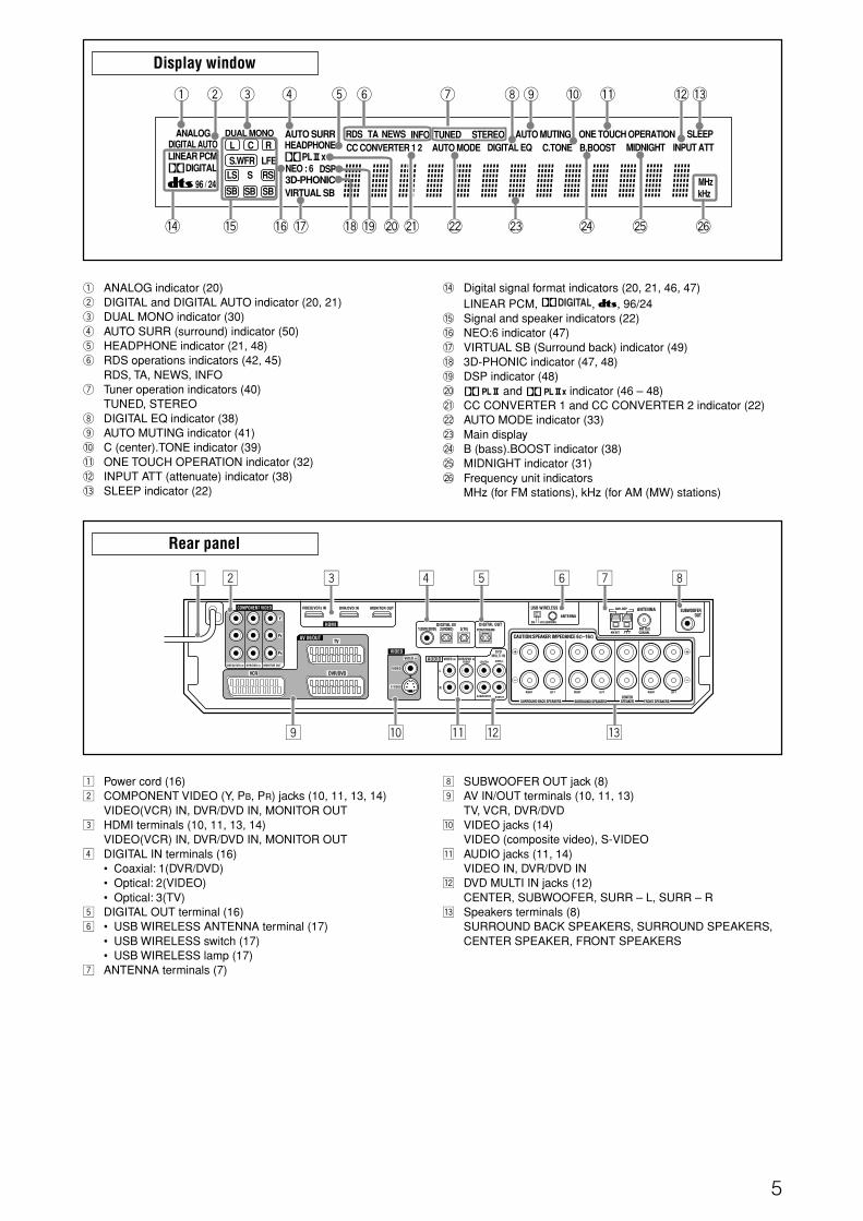
! Digital signal format indicators (20, 21, 46, 47)LINEAR PCM, , , 96/24
@ Signal and speaker indicators (22)# NEO:6 indicator (47)$ VIRTUAL SB (Surround back) indicator (49)% 3D-PHONIC indicator (47, 48)^ DSP indicator (48)& and indicator (46 – 48)* CC CONVERTER 1 and CC CONVERTER 2 indicator (22)( AUTO MODE indicator (33)) Main display_ B (bass).BOOST indicator (38)+ MIDNIGHT indicator (31)¡ Frequency unit indicators
MHz (for FM stations), kHz (for AM (MW) stations)
8 SUBWOOFER OUT jack (8)9 AV IN/OUT terminals (10, 11, 13)
TV, VCR, DVR/DVDp VIDEO jacks (14)
VIDEO (composite video), S-VIDEOq AUDIO jacks (11, 14)
VIDEO IN, DVR/DVD INw DVD MULTI IN jacks (12)
CENTER, SUBWOOFER, SURR – L, SURR – Re Speakers terminals (8)
SURROUND BACK SPEAKERS, SURROUND SPEAKERS,CENTER SPEAKER, FRONT SPEAKERS
1 ANALOG indicator (20)2 DIGITAL and DIGITAL AUTO indicator (20, 21)3 DUAL MONO indicator (30)4 AUTO SURR (surround) indicator (50)5 HEADPHONE indicator (21, 48)6 RDS operations indicators (42, 45)
RDS, TA, NEWS, INFO7 Tuner operation indicators (40)
TUNED, STEREO8 DIGITAL EQ indicator (38)9 AUTO MUTING indicator (41)0 C (center).TONE indicator (39)- ONE TOUCH OPERATION indicator (32)= INPUT ATT (attenuate) indicator (38)~ SLEEP indicator (22)
Display window
VIDEO IN DVR/DVD INFRONT
DIGITAL IN2(VIDEO)1(DVR/DVD)
LEFTRIGHT LEFTRIGHT LEFTRIGHT
ANTENNA
COAXIAL
AM LOOP
FM 75 AM EXT
SUBWOOFEROUT
3(TV)DIGITAL OUT
PCM/STREAM
ANTENNA
USB WIRELESS
CAUTION:SPEAKER IMPEDANCE 6 -16
CENTER
SUBWOOFER
SURR-L
SURR-R
LEARNINGIDON
VCR
TV
DVR/DVD
AV IN/OUT
VIDEO IN
VIDEO
S-VIDEO
VIDEO
AUDIO
L
R
FRONT SPEAKERSCENTER
SPEAKERSURROUND BACK SPEAKERS SURROUND SPEAKERS
VIDEO(VCR) IN DVR/DVD IN MONITOR OUT
HDMI
1 3 7 8
9 p w
4 5
Y
PB
COMPONENT VIDEO
MONITOR OUTDVR/DVD INVIDEO(VCR) IN
PR
2 6
q e
DIGITAL EQLINEAR PCM
L
LS
SB
RSS.WFR PL
NEO : 6 DSP3D-PHONIC
LFE
C R
96 / 24
AUTO SURRC.TONE
VIRTUAL SB
B.BOOSTTUNED STEREO SLEEPAUTO MUTING
INPUT ATTHEADPHONE
MHzkHz
xMIDNIGHT
DIGITAL
DIGITAL AUTOANALOG DUAL MONO
SB
S
SB
RDS TA NEWS INFO ONE TOUCH OPERATIONCC CONVERTER 1 2 AUTO MODE
1 2 3 5 87
^# $! @
= ~
%
4 6 -09
& * ( ) _ + ¡
01-08RX-D701S[B]_f.p65 05.11.7, 2:54 PM5

6
Putting batteries in the remote controlBefore using the remote control, put two supplied batteries first.
1 Press and slide the battery cover on the backof the remote control.
2 Insert batteries.Make sure to match the polarity: (+) to (+) and (–) to (–).
3 Replace the cover.
If the range or effectiveness of the remote control decreases,replace the batteries. Use two R6(SUM-3)/AA(15F) type dry-cellbatteries.• Supplied butteries are for initial setup. Replace for continued
use.
CAUTION:
Follow these precautions to avoid leaking or cracking cells:• Place batteries in the remote control so they match the polarity:
(+) to (+) and (–) to (–).• Use the correct type of batteries. Batteries that look similar may
differ in voltage.• Always replace both batteries at the same time.• Do not expose batteries to heat or flame.
When using the remote control, aim the remote control directly atthe remote sensor on the front panel.
Getting started
Before InstallationGeneral precautions• Be sure your hands are dry.• Turn the power off to all components.• Read the manuals supplied with the components you are going
to connect.
Locations• Install the receiver in a location that is level and protected from
moisture and dust.• The temperature around the receiver must be between –5˚C
and 35˚C.• Make sure there is good ventilation around the receiver. Poor
ventilation could cause overheating and damage the receiver.• Leave sufficient distance between the receiver and the TV.
Handling the receiver• Do not insert any metal object into the receiver.• Do not disassemble the receiver or remove screws, covers, or
cabinet.• Do not expose the receiver to rain or moisture.• Do not pull on the power cord to unplug the cord. When
unplugging the cord, always grasp the plug so as not to damagethe cord.
• When you are away on travel or otherwise for an extendedperiod or time, remove the plug from the wall outlet. A smallamount of power is always consumed while the power cord isconnected to the wall outlet.
The receiver has a built-in cooling fan which operateswhile the receiver is turned on. Be sure to leave enoughventilation to obtain sufficient cooling effect.
CAUTION:
Do not connect the AC power plug to the wall outlet until allconnections are completed.
Checking the supplied accessoriesCheck to be sure you have all of the following suppliedaccessories. If anything is missing, contact your dealerimmediately.
• Remote control (× 1)• Batteries (× 2)• AM (MW) loop antenna (× 1)• FM antenna (× 1)• USB wireless antenna (× 1)• USB wireless transmitter (Model number: QAL0708-002) (× 1)• USB extension cable (60 cm) (× 1)
Remote sensor
1 2 3
01-08RX-D701S[B]_f.p65 05.11.7, 2:54 PM6

7
ANTENNA
COAXIALFM 75
AM EXT
AM LOOP
ANTENNA
Snap the tabs on theloop into the slots ofthe base to assemblethe AM (MW) loopantenna.
Connecting the FM and AM (MW) antennasDo not connect the AC power plug to the wall outlet until all connections are completed.
AM (MW) loop antenna(supplied)
If AM (MW) reception is poor,connect an outdoor single vinyl-covered wire (not supplied).
AM (MW) antenna connectionConnect the AM (MW) loop antenna supplied to the AM LOOPterminals.Connect the white cord to the AM EXT terminal, and connect theblack cord to the H terminal.Turn the loop until you have the best reception.• If the reception is poor, connect an outdoor single vinyl-covered
wire (not supplied) to the AM EXT terminal. Keep the AM (MW)loop antenna connected.
FM antenna connectionConnect the FM antenna supplied to the FM 75 Ω COAXIALterminal as a temporary measure.Extend the supplied FM antenna horizontally.• If the reception is poor, connect an outdoor FM antenna (not
supplied). Before attaching a 75 Ω coaxial cable with aconnector (IEC or DIN 45325), disconnect the supplied FMantenna.
FM antenna (supplied)
NOTES
• If the AM (MW) loop antenna wire is covered withvinyl, remove the vinyl while twisting it as shownon the right.
• Make sure the antenna conductors do not touchany other terminals, connecting cords and powercord. This could cause poor reception.
If FM reception is poor, connect anoutdoor FM antenna (not supplied).
01-08RX-D701S[B]_f.p65 05.11.7, 2:54 PM7

8
FL FR
SL SR
SBL
C
SW
SBR(*SB)
SUBWOOFEROUT
LEFTRIGHT LEFTRIGHT LEFTRIGHT
CAUTION:SPEAKER IMPEDANCE 6 -16
FRONT SPEAKERSCENTER
SPEAKERSURROUND BACK SPEAKERS SURROUND SPEAKERS
Connecting the speakersDo not connect the AC power plug to the wall outlet until all connections are completed.
Speaker Layout Diagram
CAUTIONS:
• Use speakers with the SPEAKER IMPEDANCE indicated by thespeaker terminals (6 Ω – 16 Ω).
• DO NOT connect more than one speaker to one speakerterminal.
Connecting the speakersTurn off all components before making connections.
1 Twist and remove the insulation at the end of eachspeaker cord.
2 Turn the knob counterclockwise.
3 Insert the speaker cord.
• For each speaker, connect the (+) and (–) terminals on therear panel to the (+) and (–) terminals marked on thespeakers.
4 Turn the knob clockwise.
*When using a single speaker for the surround back speakerYou can enjoy the surround sound by one surround backspeaker. When using one surround back speaker,– set “S BACK OUT” to “S BACK OUT: 1SPK” (see page 29) and– connect the surround back speaker to the left surround back
speaker terminal. (No sound comes from the speaker ifyou connect it to the right surround back speakerterminal.)
Connecting the powered subwooferBy connecting a subwoofer, you can enhance the bass orreproduce the original LFE signals recorded in digital software.
Connect the input jack of a powered subwoofer to theSUBWOOFER OUT jack on the rear panel, using a cordwith RCA pin plugs (not supplied).
• Refer also to the manual supplied with your subwoofer.
After connecting all the speakers and/or a subwoofer, set thespeaker setting information properly to obtain the best possiblesurround effect. For details, see pages 23, 24, 28, and 29.
NOTE
You can place a subwoofer wherever you like since bass sound isnon-directional. Normally place it in front of you.
Centerspeaker (C)
*Left surroundback speaker
(SBL)
Right surroundspeaker (SR)
Left surroundspeaker (SL)
Left frontspeaker
(FL)
Right frontspeaker
(FR)
Poweredsubwoofer
(SW)
Right surroundback speaker
(SBR)
1 32 4
01-08RX-D701S[B]_f.p65 05.11.7, 2:54 PM8

9
Before connecting video componentsAbout HDMI
IMPORTANT:
The HDMI video signals from the HDMI terminal are transmitted only through the HDMI MONITOR OUT terminal.Therefore, if the TV is connected to the receiver through the AV IN/OUT terminal (TV) or COMPONENT VIDEO jacks (MONITOR OUT)and a playing video component is connected to the receiver through the HDMI terminal (VIDEO (VCR) IN or DVR/DVD IN), you cannotview the playback picture on the TV.
About SCART
You can enjoy pictures and sounds from playback components simply by connecting with the SCART cable.
• For an analogue decoderTo watch through or to record a scrambled program on your VCR, connect the analogue decoder to your VCR and select thescrambled channel on your VCR.If an appropriate terminal for the decoder connection is not equipped for your VCR, connect the decoder to your TV.Refer also to the manuals supplied with these components.
• For T-V LINK• You can use the T-V LINK function if you connect a T-V LINK compatible TV and VCR to this receiver with a fully wired SCART
cables. For details on T-V LINK, refer also to the manuals supplied with the TV and the VCR.• Connect a SCART cable to EXT-2 terminal on the JVC’s T-V LINK compatible TV for the T-V LINK function.• Some video components support the data communication like T-V LINK. For complete details, refer also to the manuals supplied with
these components.
Connecting video componentsDo not connect the AC power plug to the wall outlet until all connections are completed.
Video conversion functionThis receiver can convert the video signals output from video components. The chart below shows which video signals can be convertedinto which signals by video conversion.
NOTES
• HDMI and RGB signals cannot be converted into other video signals.• With HDMI signals transmitted or input video signals converted into HDMI signals, the playback picture may be distorted when you
change the playback mode (fast-forward, rewind, or pause, for example).
To use the video conversion function, you need to make the twosettings below when you finish connecting your TV and videocomponents.
VIDEO OUTPUT: Select the settings according to theconnection method for your TV. Seepages 10 and 33 for details.
VIDEO INPUT: Select the settings according to theconnection method for your videocomponents. This setting is memorizedfor each source. See pages 11 to 15 and20 for details.
Converted video signals available vary depending on each sourcecomponent. See also page 10 to 15 for details.
Video Input Converted Video Output
CMPNT (component)
S (S-video)
C (composite)
CMPNT (component)
S (S-video)
C (composite)
HDMIHDMI
RGBRGB
SCART Terminal Specifications : Available, –: Not available
Terminal name
TV VCR DVR/DVD
Audio L/R
InputComposite
Video S-video (Y/C) –
RGB –
Audio L/R –
OutputComposite *1 *1 *1
Video S-video (Y/C) – –
RGB – –
T-V LINK *2 *2 *2
*1 The signals input from a SCART terminal cannot be outputthrough the same SCART terminal.
*2 The signals for the T-V LINK function are always goingthrough the receiver.
CAUTION:
If you connect a sound-enhancing device such as a graphic equalizer between the source components and this receiver, the soundoutput through this receiver may be distorted.
NOTES
• Composite video signals and S-video signals can be convertedinto all types of signals except RGB. See above for details.
• When you record a playback picture with a DVD recorder orVCR connected to this receiver, perform either one of the below.– Set the video input setting (see page 20) to a setting other
than “S” to transmit composite video or RGB signals to thisreceiver.
– Set “VIDEO OUTPUT” (see page 33) to “RGB/C” to transmitS-video signals from a playback component to this receiver.
09-15RX-D701S[B]_f.p65 05.11.9, 11:32 AM9

10
Y
PB
PR
COMPONENT VIDEO
MONITOR OUTDVR/DVD INVIDEO(VCR) IN
TVAV IN/OUT
MONITOR OUT
Å
ı Ç
Select the appropriate VIDEO OUTPUT (see page 33)according to the terminal used for TV connection referringto the table below.
Connection method VIDEO OUTPUTHDMI HDMIComponent CMPNTSCART (S-video) SSCART (RGB or composite) RGB/C
7 Connecting a TV:
HDMI cable (not supplied)
SCART cable (not supplied)
Green
Blue
Red
Component video cable (not supplied)
TV
Å To component video input• Connect Y, PB, and PR correctly.
ı To HDMI inputÇ To SCART terminal
NOTES
• To enjoy TV sound through this receiver or record a TV program with a DVD recorder or VCR connected to this receiver, connect yourTV with the SCART cable as well when connecting with the HDMI or component video cable. However, the input setting of the TV maychange to SCART input with some TVs or sources regardless of “VIDEO OUTPUT” (see page 33).
• The on-screen display does not appear on the TV screen in the following conditions:– When connecting your TV only with the HDMI cable and setting the video input setting (see page 20) to “HDMI.” Set the video input
setting to a setting other than “HDMI” to use the on-screen display.– When connecting your TV only with the SCART cable and setting the video input setting to “RGB.” Set the video input setting to a
setting other than “RGB” to use the on-screen display.• When playing back audio and video with the HDMI connection, the HDMI lamp on the front panel lights up.• Select the audio and video input setting according to the connection method. See page 20 for details.• Set the audio input setting to “HDMI” when you enjoy sound with the HDMI connection. See “Selecting the audio input setting” on page
20.• By using a HDMI-DVI conversion cable, you can connect the source components or the TV with DVI output. When connecting those
components or TV, change the audio input setting to the setting other than “HDMI.” (See page 20.)• This receiver is compatible with standard video formats. If non-standard video formats are coming in, the picture may not appear
properly on TV.• The picture on the TV may not be the same aspect ratio as the ratio set on the source components.• When connecting a TV to this receiver with an HDMI cable, the sound coming into this receiver is not transmitted to the speakers of
the TV. You can enjoy sound only from the speakers connected to this receiver.• When connecting a TV to this receiver with an HDMI cable, turning a source component on or off, or changing the audio or video input
setting of this receiver frequently may cause a noise or interrupt the sound and picture. In this case, turn the receiver off and turn it onagain.
• When you enjoy contents protected by HDCP (High-Bandwidth Digital Content Protection, see page 1), connect a HDCP-compatibleTV to this receiver, otherwise, the picture may not appear properly.
• When you enjoy HDCP contents, sound and picture may not be transmitted to the speakers and TV for a few seconds in the beginningfor confirmation.
Turn off all components before makingconnections.
Do not connect the AC power plug to the wall outlet until all connections are completed.
: signal current
DO NOT use a TV through a VCR or a TV with a built-inVCR; otherwise, the picture may be distorted.
09-15RX-D701S[B]_f.p65 05.11.9, 11:32 AM10

11
VIDEO IN DVR/DVD INFRONT
L
R
AUDIO
) IN DVR/DVD IN
HDMI
DVR/DVD
Å ı
Y
PB
PR
COMPONENT VIDEO
MONITOR OUTDVR/DVD INVIDEO(VCR) IN
Ç Î
7 Connecting a DVD recorder or DVD player:
HDMI cable (not supplied)
SCART cable (not supplied)
Green
Blue
Red
Component video cable (not supplied)
Stereo audio cable(not supplied)
DVD recorder orDVD player
Available video input setting for each video output setting:: Available –: Not available
HDMI CMPNT S C RGB
HDMI –
CMPNT – –
S – – –
RGB/C – –
Å To HDMI outputı To component video output
• Connect Y, PB, and PR correctly.Ç To left/right audio channel outputÎ To SCART terminal
NOTES
• Do not connect different components to the AUDIO DVR/DVD IN jacks and AV IN/OUT (SCART) DVR/DVD terminal; otherwise,sounds from both components come out of the speakers at the same time.
• When playing back audio and video with the HDMI connection, the HDMI lamp on the front panel lights up.• Select the audio and video input setting according to the connection method. See page 20 for details.• Set the audio input setting to “HDMI” when you enjoy sound with the HDMI connection. See “Selecting the audio input setting” on page
20.• By using a HDMI-DVI conversion cable, you can connect the source components or the TV with DVI output. When connecting those
components or TV, change the audio input setting to the setting other than “HDMI.” (See page 20.)• In addition to using the HDMI cable, you can enjoy digital sound as well using a digital audio cable (coaxial or optical). When shipped
from the factory, the digital coaxial terminal (DIGITAL IN 1 (DVR/DVD)) on the rear of the receiver is set for a DVD recorder and DVDplayer. For details of digital audio connection, see page 16.
• If your DVD recorder or DVD player is equipped with the analogue multi channel output terminals, you can enjoy the sound recorded inDVD-Audio by connecting your DVD recorder or DVD player to DVD MULTI IN jacks. See page 12 for details.When you enjoy the sound recorded in DVD-Audio with HDMI connection, see “When you enjoy sound recorded in DVD-Audio...” onpage 12.
• When enjoying multi channel PCM sound with the audio input setting set to “HDMI” (see page 20), some functions are not available.See page 12 for details.
Turn off all components before makingconnections.
Do not connect the AC power plug to the wall outlet until all connections are completed.
: signal current
VIDEO INPUTVIDEOOUTPUT
Select the appropriate VIDEO INPUT (see page 20) according to theconnection you have made. If you do not, you cannot view the playbackpicture on the TV.
White
Red
09-15RX-D701S[B]_f.p65 05.11.7, 2:54 PM11

12
Å ı
Î
Ç
DVR/DVD INFRONT
DVDMULTI IN
CENTER
SUBWOOFER
SURR-L
SURR-R
When you connect a DVD recorder or DVD player with its analogue discrete output jacks (DVD MULTI IN):If your DVD recorder or DVD player has analogue 5.1 channel output jacks, use the connection below. When a DVD Audio disc is playedback, the original high-quality sounds can be reproduced by using this connection.For video connection, see page 11.
Turn off all components before makingconnections.
Stereo audio cable (not supplied)
Monaural audio cable(not supplied)
Monaural audio cable(not supplied)
Stereo audio cable(not supplied)
DVD recorder orDVD player
White
Red
White
Red
When you enjoy sound recorded in DVD-Audio...You can enjoy sound recorded in DVD-Audio both with analogue or digital methods.– With analogue method:
• connect your DVD recorder or DVD player to this receiver according to the diagram above.• select “A MULTI” in the audio input setting. (See page 20.)
– With digital method:• connect your DVD recorder or DVD player and TV to this receiver with the HDMI cables. (See page 11.)• select “HDMI” in the audio input setting. (See page 20.)
NOTES
• When selecting “A MULTI” in the audio input setting or when multi channel PCM signals (see page 47) are coming in with selecting“HDMI” in the audio input setting, you can listen to the front channel sounds (left and right) only by using the headphones. 3DHEADPHONE mode (see page 48) is not available.
• When selecting “A MULTI” in the audio input setting or when multi channel PCM signals (see page 47) are coming in with selecting“HDMI” in the audio input setting, the following items are not available:
– DECODE MODE (see page 21)– CC Converter (see page 22)– EX/ES/PLllx (see page 30)– DUAL MONO (see page 30)– SUBWFR OUT (see page 30)– CROSSOVER (see page 31)– LFE ATT (see page 31)– MIDNIGHT (see page 31)– AUDIO DELAY (see page 32)– DIGITAL EQ 63Hz/250Hz/1kHz/4kHz/16kHz (see page 38)– BASS BOOST (see page 38)– INPUT ATT (see page 38)– Sound parameters for Surround/DSP modes (see pages 38 and 39)– Surround/DSP modes (see pages 46 to 50)
• When you enjoy sound recorded in DVD-Audio through the HDMI connection, use a DVD recorder or DVD player compatible withHDMI version 1.1.
Å To left/right surround channel audio outputı To center channel audio outputÇ To left/right front channel audio outputÎ To subwoofer output
NOTE
Do not connect different components to the DVD MULTI IN jacksand AV IN/OUT (SCART) DVR/DVD terminal (see page 11);otherwise, sounds from both components come out of thespeakers at the same time.
Do not connect the AC power plug to the wall outlet until all connections are completed.
: signal current
09-15RX-D701S[B]_f.p65 05.11.7, 2:54 PM12

13
Y
PB
PR
COMPONENT VIDEO
MONITOR OUTDVR/DVD INVIDEO(VCR) IN
ıÅ
VIDEO(VCR) IN
HDMI
VCR
Ç
Do not connect the AC power plug to the wall outlet until all connections are completed.
7 Connecting a VCR:
Å To HDMI outputı To component video output
• Connect Y, PB, and PR correctly.Ç To SCART terminal
HDMI cable (not supplied)
SCART cable (not supplied)
Green
Blue
Red
Component video cable (not supplied)
Turn off all components before makingconnections.
VCR
NOTES
• When playing back audio and video with the HDMI connection, the HDMI lamp on the front panel lights up.• Select the audio and video input setting according to the connection method. See page 20 for details.• Set the audio input setting to “HDMI” when you enjoy sound with the HDMI connection. See “Selecting the audio input setting” on page
20.• In addition to using the HDMI cable, you can enjoy digital sound as well using a digital audio cable (coaxial or optical). For details of
digital audio connection, see page 16.• When connecting a VCR with a HDMI cable or component video cable, set “HDMI SELECT” or “CMPNT SELECT” to “VCR.” (See
page 32.)
: signal current
Available video input setting for each video output setting:: Available –: Not available
HDMI CMPNT S C RGB
HDMI –
CMPNT – –
S – – –
RGB/C – –
VIDEO INPUTVIDEOOUTPUT
Select the appropriate VIDEO INPUT (see page 20) according to theconnection you have made. If you do not, you cannot view the playbackpicture on the TV.
09-15RX-D701S[B]_f.p65 05.11.7, 2:54 PM13

14
Y
PB
PR
COMPONENT VIDEO
MONITOR OUTDVR/DVD INVIDEO(VCR) IN
ÎVIDEO IN
VIDEO
S-VIDEO
VIDEOVIDEO IN DVR/DVD IN
FRONT
L
R
AUDIO
‰Ç
ıÅ
VIDEO(VCR) IN
HDMI
Do not connect the AC power plug to the wall outlet until all connections are completed.
7 Connecting another video component to the VIDEO IN jacks: Turn off all components before makingconnections.
Stereo audio cable(not supplied)
White
Component video cable (not supplied)
Composite video cable (not supplied)
S-video cable (not supplied)
Red
Green
Blue
Red
Å To HDMI outputı To component video output
• Connect Y, PB, and PR correctly.Ç To left/right audio channel outputÎ To composite video output‰ To S-video output
NOTES
• When playing back audio and video with the HDMI connection, the HDMI lamp on the front panel lights up.• Select the audio and video input setting according to the connection method. See page 20 for details.• Set the audio input setting to “HDMI” when you enjoy sound with the HDMI connection. See “Selecting the audio input setting” on page
20.• In addition to using the HDMI cable, you can enjoy digital sound as well using a digital audio cable (coaxial or optical). When shipped
from the factory, the digital optical terminal (DIGITAL IN 2 (VIDEO)) on the rear of the receiver is set for a video component other thanDVD recorder and DVD player. For details of digital audio connection, see page 16.
• When connecting another video component with a HDMI cable or component video cable, set “HDMI SELECT” or “CMPNT SELECT”to “VIDEO.” (See page 32.)
HDMI cable (not supplied)
DBS tuner, etc.
: signal current
Available video input setting for each video output setting:: Available –: Not available
HDMI CMPNT S C RGB
HDMI –
CMPNT – –
S – – –
RGB/C – – –
VIDEO INPUTVIDEOOUTPUT
Select the appropriate VIDEO INPUT (see page 20) according to theconnection you have made. If you do not, you cannot view the playbackpicture on the TV.
09-15RX-D701S[B]_f.p65 05.11.9, 11:32 AM14

15
DIGITALS-VIDEO
VIDEO L – AUDIO – R
AUX
ı Ç
ÅÎ
7 Connecting a video component to the AUX input jacks:The AUX input jacks on the front panel (inside the front door) are convenient when connecting and disconnecting the componentfrequently.Before making connections, press PUSH-OPEN to show the jacks.To enjoy the playback from the component connected to these jacks, select “AUX” as the source (see page 19).
Å To left/right audio channel outputı To composite video outputÇ To S-video outputÎ To digital optical output
NOTE
Select the audio and video input setting according to the connection method. See page 20 for details.
Stereo audio cable(not supplied)
Composite video cable (not supplied)
S-video cable (not supplied)
Digital optical cable (not supplied)
Video camera, etc.
: signal current
Available video input setting for each video output setting:: Available –: Not available
HDMI CMPNT S C RGB
HDMI – – –
CMPNT – – –
S – – –
RGB/C – – –
VIDEO INPUTVIDEOOUTPUT
Select the appropriate VIDEO INPUT (see page 20) according to theconnection you have made. If you do not, you cannot view the playbackpicture on the TV.
How to open the front door
Red
White
Do not connect the AC power plug to the wall outlet until all connections are completed.
Turn off all components before makingconnections.
09-15RX-D701S[B]_f.p65 05.11.7, 2:54 PM15
16
DIGITAL IN2(VIDEO)1(DVR/DVD) 3(TV)
DIGITAL OUTPCM/STREAM
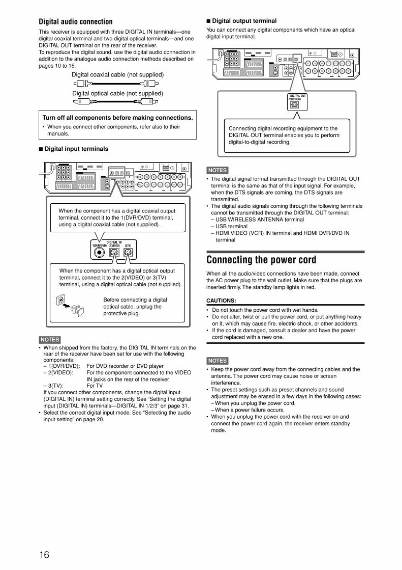
NOTES• When shipped from the factory, the DIGITAL IN terminals on the
rear of the receiver have been set for use with the followingcomponents:– 1(DVR/DVD): For DVD recorder or DVD player– 2(VIDEO): For the component connected to the VIDEO
IN jacks on the rear of the receiver– 3(TV): For TVIf you connect other components, change the digital input(DIGITAL IN) terminal setting correctly. See “Setting the digitalinput (DIGITAL IN) terminals—DIGITAL IN 1/2/3” on page 31.
• Select the correct digital input mode. See “Selecting the audioinput setting” on page 20.
Digital audio connectionThis receiver is equipped with three DIGITAL IN terminals—onedigital coaxial terminal and two digital optical terminals—and oneDIGITAL OUT terminal on the rear of the receiver.To reproduce the digital sound, use the digital audio connection inaddition to the analogue audio connection methods described onpages 10 to 15.
Digital coaxial cable (not supplied)
Digital optical cable (not supplied)
Turn off all components before making connections.• When you connect other components, refer also to their
manuals.
7 Digital input terminals
When the component has a digital coaxial outputterminal, connect it to the 1(DVR/DVD) terminal,using a digital coaxial cable (not supplied).
When the component has a digital optical outputterminal, connect it to the 2(VIDEO) or 3(TV)terminal, using a digital optical cable (not supplied).
Before connecting a digitaloptical cable, unplug theprotective plug.
NOTES
• The digital signal format transmitted through the DIGITAL OUTterminal is the same as that of the input signal. For example,when the DTS signals are coming, the DTS signals aretransmitted.
• The digital audio signals coming through the following terminalscannot be transmitted through the DIGITAL OUT terminal:– USB WIRELESS ANTENNA terminal– USB terminal– HDMI VIDEO (VCR) IN terminal and HDMI DVR/DVD IN
terminal
Connecting the power cordWhen all the audio/video connections have been made, connectthe AC power plug to the wall outlet. Make sure that the plugs areinserted firmly. The standby lamp lights in red.
CAUTIONS:
• Do not touch the power cord with wet hands.• Do not alter, twist or pull the power cord, or put anything heavy
on it, which may cause fire, electric shock, or other accidents.• If the cord is damaged, consult a dealer and have the power
cord replaced with a new one.
NOTES
• Keep the power cord away from the connecting cables and theantenna. The power cord may cause noise or screeninterference.
• The preset settings such as preset channels and soundadjustment may be erased in a few days in the following cases:– When you unplug the power cord.– When a power failure occurs.
• When you unplug the power cord with the receiver on andconnect the power cord again, the receiver enters standbymode.
7 Digital output terminalYou can connect any digital components which have an opticaldigital input terminal.
Connecting digital recording equipment to theDIGITAL OUT terminal enables you to performdigital-to-digital recording.
16-18RX-D701S[B].p65 05.11.7, 2:54 PM16

17
4 Turn on the receiver, then slide the USB WIRELESSswitch on the rear to “ID LEARNING,” and select thesource as “USB WIRELESS.”When you slide the switch, the lamp in the switch startsflashing.
5 Set the volume to minimum.
IMPORTANT:
Always set volume to “0” when connecting or disconnecting theother equipment.
6 Press and hold ID on the transmitter to make a wirelesscommunication with the receiver.When you press and hold the button, the ID lamp on thetransmitter flashes.
When the receiver recognizes the transmitter, the lamp on therear of the receiver stops flashing and lights up.
7 Slide the switch on the receiver to “ON.”• If you do not, no sound signal is transmitted to the receiver.
NOTES
• The signal-reachable distance is about 30 m, but it may differdepending on the operating conditions and circumstances.
• The PLAYER lamp on the transmitter keeps flashing whenstarting the playback software in your PC.
• If no signals are transmitted from the transmitter for about 30minutes, the transmitter enters “sleep” mode. The “L” and “R”indicators go off from the display.
• Though the transmitter may become hot, it is not a malfunction.
2 For USB TERMINAL
1 Turn on your PC.• If the PC has been turned on, quit all the applications now
running.
2 Turn on the receiver, and select the source as “USBTERMINAL.”
3 Set the volume to minimum.
IMPORTANT:
Always set volume to “0” when connecting or disconnecting theother equipment.
4 Connect the receiver to the PC using a USB cable (notsupplied).
• Use “USB series A plug to B plug” cable when connecting.
USB
USB connectionThis receiver is equipped with a USB terminal on the front paneland a USB WIRELESS ANTENNA terminal on the rear. You canenjoy the sound reproduced through your PC with either of thefollowing methods:1 connecting a USB wireless antenna (supplied) to the USB
WIRELESS ANTENNA terminal and a USB wirelesstransmitter (supplied) to your PC. (USB WIRELESS)
2 connecting your PC to the USB terminal with a USB cable (notsupplied). (USB TERMINAL)
When you connect your PC for the first time, follow the procedurebelow.• Remember you cannot send any signal or data to your PC from
this receiver.• Use USB extension cable (supplied) if it is difficult to connect
the transmitter directly to the USB connector or the transmitterbecomes obstacle to other USB connectors.
IMPORTANT:
Check if your PC equipped with the CD-ROM drive is running onWindows® 98 SE*, Windows® Me*, Windows® 2000* or Windows®
XP* and prepare its CD-ROM.
Preparation
1 For USB WIRELESS
Be sure to make USB WIRELESS communicationbefore connection and installation of the receiver.During the procedure, you need to check the statusof the lamp on the rear of the receiver (turning on orflashing).
1 Connect the antenna to the USB WIRELESS ANTENNAterminal on the rear panel.• Tighten the screw with the antenna upright.
2 Turn on your PC.• If the PC has been turned on, quit all the applications now
running.
3 Connect the USB wireless transmitter to the USBconnector of the PC.Before connecting the transmitter to the PC, remove the coverof the transmitter.When you connect the transmitter, the USB drivers areinstalled. The POWER and PLAYER lamp on the transmitterlight up.
ANTENNA
USB WIRELESS
LEARNINGIDON
USB wirelesstransmitter (supplied)
USB wirelessantenna
(supplied)
USB cable(not supplied)
PC
USB WIRELESS TRANSMITTER
IDCHANNEL POWER PLAYERID
USB WIRELESS TRANSMITTER
POWER PLAYERID
USB WIRELESS TRANSMITTER
PC
CONTINUED ON THE NEXT PAGE
16-18RX-D701S[B].p65 05.11.18, 10:01 AM17
18
Now PC is ready for playback through the USB connection.
After installation is completed, you can use your PC as theplayback source. The PC automatically recognizes the receiverwhenever the transmitter is connected to the PC or the USB cableis connected between the PC and the receiver while the receiveris turned on.• When not using the PC as the playback source, disconnect the
transmitter or the USB cable.
To play back sounds on the PC, refer to the manuals suppliedwith the sound reproduction application installed in the PC. Startthe application after the USB device is recognized.
When playing back with USB WIRELESS, connect thetransmitter and aim the transmitter at the antenna. If anyobstacles are in between, playback will be interrupted or thewireless communication will be canceled.
If noise comes during playback or playback is interruptedwith USB WIRELESS, try measures below:– press CHANNEL on the transmitter to search for another
frequency. Each time you press CHANNEL, the frequencyadvances one channel up from CH 1 up to CH 13.
– press and hold CHANNEL for more than three seconds to makesure the transmitter detects the best frequency automatically.
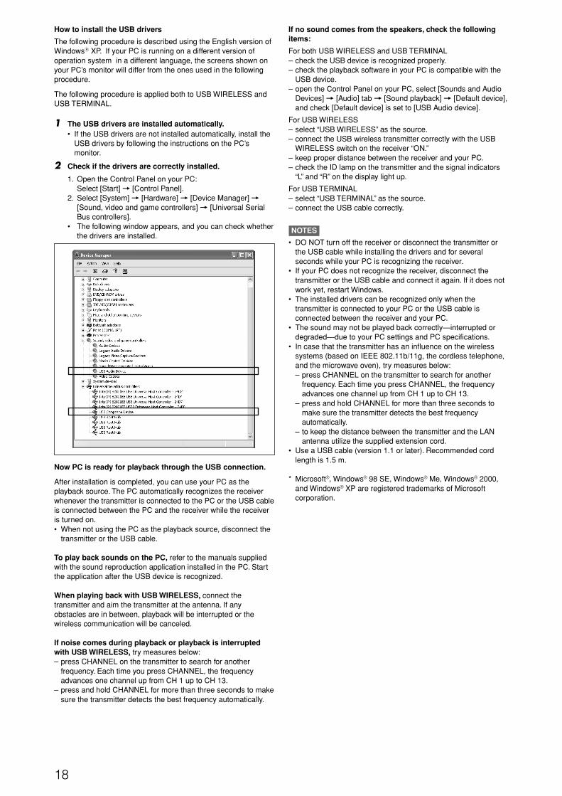
How to install the USB drivers
The following procedure is described using the English version ofWindowsR XP. If your PC is running on a different version ofoperation system in a different language, the screens shown onyour PC’s monitor will differ from the ones used in the followingprocedure.
The following procedure is applied both to USB WIRELESS andUSB TERMINAL.
1 The USB drivers are installed automatically.• If the USB drivers are not installed automatically, install the
USB drivers by following the instructions on the PC’smonitor.
2 Check if the drivers are correctly installed.
1. Open the Control Panel on your PC:Select [Start] = [Control Panel].
2. Select [System] = [Hardware] = [Device Manager] =[Sound, video and game controllers] = [Universal SerialBus controllers].
• The following window appears, and you can check whetherthe drivers are installed.
If no sound comes from the speakers, check the followingitems:
For both USB WIRELESS and USB TERMINAL– check the USB device is recognized properly.– check the playback software in your PC is compatible with the
USB device.– open the Control Panel on your PC, select [Sounds and Audio
Devices] = [Audio] tab = [Sound playback] = [Default device],and check [Default device] is set to [USB Audio device].
For USB WIRELESS– select “USB WIRELESS” as the source.– connect the USB wireless transmitter correctly with the USB
WIRELESS switch on the receiver “ON.”– keep proper distance between the receiver and your PC.– check the ID lamp on the transmitter and the signal indicators
“L” and “R” on the display light up.
For USB TERMINAL– select “USB TERMINAL” as the source.– connect the USB cable correctly.
NOTES
• DO NOT turn off the receiver or disconnect the transmitter orthe USB cable while installing the drivers and for severalseconds while your PC is recognizing the receiver.
• If your PC does not recognize the receiver, disconnect thetransmitter or the USB cable and connect it again. If it does notwork yet, restart Windows.
• The installed drivers can be recognized only when thetransmitter is connected to your PC or the USB cable isconnected between the receiver and your PC.
• The sound may not be played back correctly—interrupted ordegraded—due to your PC settings and PC specifications.
• In case that the transmitter has an influence on the wirelesssystems (based on IEEE 802.11b/11g, the cordless telephone,and the microwave oven), try measures below:– press CHANNEL on the transmitter to search for another
frequency. Each time you press CHANNEL, the frequencyadvances one channel up from CH 1 up to CH 13.
– press and hold CHANNEL for more than three seconds tomake sure the transmitter detects the best frequencyautomatically.
– to keep the distance between the transmitter and the LANantenna utilize the supplied extension cord.
• Use a USB cable (version 1.1 or later). Recommended cordlength is 1.5 m.
* Microsoft®, Windows® 98 SE, Windows® Me, Windows® 2000,and Windows® XP are registered trademarks of Microsoftcorporation.
16-18RX-D701S[B].p65 05.11.7, 2:54 PM18

19
Basic operations 2 Select the source to playOn the front panel:Turn SOURCE SELECTOR until the source nameyou want appears on the display.The source lamp corresponding to the selected source lights inred.• As you turn SOURCE SELECTOR, the source changes as
follows:
DVR/DVD: Select this for the DVD recorder or DVDplayer.
VCR: Select this for the VCR.VIDEO: Select this for the component connected
to the VIDEO IN jacks on the rear of thereceiver.
TV: Select this for the TV.USB WIRELESS: Select this for the PC component using
a wireless equipment.USB TERMINAL: Select this for the PC component.FM: Select this for an FM broadcast.AM: Select this for an AM (MW) broadcast.AUX: Select this for the component connected
to the AUX jacks on the front panel(inside the front door).
From the remote control:Press one of the source selecting buttons.• For “USB WIRELESS” and “USB TERMINAL,” press USB. Each
time you press USB, the mode alternates between “USBWIRELESS” and “USB TERMINAL.”
• For “FM” and “AM,” press FM/AM. Each time you press FM/AM,the mode alternates between “FM” and “AM.”
NOTE
When connecting a video component to HDMI VIDEO (VCR) INterminal or COMPONENT VIDEO (VCR) IN jacks, “VCR” and“VIDEO” are assigned for the source you have selected in “HDMISELECT” and “CMPNT SELECT” (see page 32).
Source lamps
1 Turn on the powerPress STANDBY/ON (or AUDIO on theremote control).The standby lamp goes off and the source lamp of the currentsource lights in red.
Current source name appears.
To turn off the power (into standby)Press STANDBY/ON (or AUDIO on the remote control)again.The standby lamp lights in red.
NOTES
• A small amount of power is consumed in standby mode. To turnthe power off completely, unplug the AC power cord.
• Turning a source component on before turning the receiver onmay cause a noise or interrupt the sound and picture. In thiscase, turn both the source component and the receiver off, thenturn the receiver on before turning the source component on.
L
S.WFR
RAUTO SURR TUNED STEREO AUTO MUTING
MHz
ANALOG
L
S.WFR
RAUTO SURR TUNED STEREO AUTO MUTING
MHz
ANALOG
DVR/DVD VCR VIDEO TV
FM AM(Back to the beginning)
USB WIRELESS USB TERMINALAUX
1 2 3
1 2 3
4 5 6
7 8 9
10 0 10
1
3
2
19-22RX-D701S[B]_f.p65 05.11.7, 2:54 PM19

20
* When “TV” is selected as the source, only “DIGITAL” or“ANALOGUE” appears on the display as the audio inputsetting.
NOTES
• “HDMI” is available only for the source with “HDMI” selected inthe video input setting (see the left column).
• “DIGITAL” is available for the source assigned for “DIGITAL IN1,” “DIGITAL IN 2,” or “DIGITAL IN 3.” See page 25 for details.
Initial setting of VIDEO INPUT and AUDIO INPUT foreach source
DVR/DVD HDMI HDMI
VCR S ANALOG
VIDEO HDMI HDMI
TV DIGITAL
USB WIRELESS DIGITAL (fixed)
USB TERMINAL DIGITAL (fixed)
FM ANALOG (fixed)
AM ANALOG (fixed)
AUX S DIGITAL
3 Adjust the volumeTo increase the volume, turn MASTER VOLUMEcontrol clockwise (or press VOLUME + on theremote control).To decrease the volume, turn MASTER VOLUMEcontrol counterclockwise (or press VOLUME – onthe remote control).• When you adjust the volume, the volume level indication
appears on the display for a while.
CAUTION:
Always set the volume to the minimum before starting anysources. If the volume is set at its high level, the sudden blast ofsound energy can permanently damage your hearing and/or ruinyour speakers.
NOTE
The volume level can be adjusted within the range of “0” (minimum)to “50” (maximum).
Selecting the video input settingSelect the proper video input setting according to the connectionmethod on pages 10 to 15.
From the remote control ONLY:Press VIDEO INPUT to select the video inputsetting.• Each time you press the button, the input setting changes as
follows. This setting is memorized for each source.
NOTES
• When “DVR/DVD” or “VCR” is selected as the source and“VIDEO OUTPUT” (see page 33) is set to “RGB/C,” the videoinput setting changes between “RGB,” “S,” and “C.”
• For “VCR” and “VIDEO,” you can select “HDMI” and “CMPNT”for the source you assigned in “HDMI SELECT” and “CMPNTSELECT” (see page 32).
• When the video input setting and the audio input setting areboth set to “HDMI,” changing the video input setting changes theaudio input setting to the appropriate setting.
Selecting the audio input settingSelect the proper audio input setting according to the connectionmethod (analogue or digital) on pages 10 to 16.• In case of digital connection using the terminals on the rear of
the receiver, you also need to select the correct digital inputterminal. (See “Setting the digital input (DIGITAL IN) terminals—DIGITAL IN 1/2/3” on page 31.)
From the remote control ONLY:Press AUDIO INPUT to select the audio inputsetting.• Each time you press the button, the audio input setting changes
as follows. This setting is memorized for each source.
HDMI (for “DVR/DVD,” “VIDEO” and “VCR”):Select for the source with HDMI connection. Thereceiver automatically detects the incomingsignal format, then the digital signal formatindicator (LINEAR PCM, , , or
96/24) for the detected signal lights up,and the HDMI lamp on the front panel lights up.
DIGITAL*: Select for the digital input setting. The receiverautomatically detects the incoming signalformat, then the digital signal format indicator(LINEAR PCM, , , or 96/24)for the detected signal lights up.
ANALOG*: Select for the analogue input setting. The(ANALOGUE) ANALOG indicator lights up on the display.
A MULTI (Only for “DVR/DVD”):Select when connecting a DVD recorder or DVDplayer to DVD MULTI IN jacks (see page 12).The ANALOG indicator lights up on the display.
L
S.WFR
RAUTO SURRANALOG
L
LS RSS.WFR LFE
C RAUTO SURR
DIGITAL
DIGITAL
HDMI CMPNT (component)
(Back to the beginning)S (S-video) C (composite)
L
LS RSS.WFR LFE
C RAUTO SURR
DIGITAL
DIGITAL
HDMI DIGITAL
A MULTI (Back to the beginning)
ANALOG
SourceSetting
VIDEO INPUT AUDIO INPUT
19-22RX-D701S[B]_f.p65 05.11.9, 11:26 AM20

21
Listening with headphonesYou can enjoy not only stereo software but also multi-channelsoftware through the headphones. (Sounds are down-mixed to thefront channels while playing multi-channel software.)
Connect a pair of headphones to the PHONES jack on thefront panel to activate the HEADPHONE mode.
The HEADPHONE indicator lights up on the display.• You can also enjoy the Surround/DSP mode through the
headphones—3D HEADPHONE mode. For details, see page48.
• Disconnecting a pair of headphones from the PHONES jackcancels the HEADPHONE (or 3D HEADPHONE) mode andactivates the speakers.
CAUTION:
Be sure to turn down the volume:• Before connecting or putting on headphones, as high volume
can damage both the headphones and your hearing.• Before removing headphones, as high volume may output from
the speakers.
Selecting the digital decode modeThis receiver automatically detects the incoming digital signalformat when “HDMI” or “DIGITAL” is selected in the audio inputsetting (see page 20). When “HDMI” or “DIGITAL” is selected, thedigital decode mode is set to “DGTL (Digital) AUTO,” and theDIGITAL AUTO indicator lights up on the display.If the following symptoms occur while playing Dolby Digital or DTSsoftware with “HDMI” or “DIGITAL” selected as the audio inputsetting (see page 20), follow the procedure below:• Sound does not come out at the beginning of playback.• Noise comes out while searching for or skipping chapters or
tracks.
From the remote control ONLY:
Press DECODE MODE to select “DOLBYDIGITAL” or “DTS.”• Each time you press DECODE MODE, the digital decode mode
changes as follows:
• To play back software encoded with Dolby Digital, select“DOLBY DIGITAL.”
• To play back software encoded with DTS, select “DTS.”
NOTE
“DOLBY DIGITAL” or “DTS” is automatically reset to “DGTL AUTO”in the following cases:– When you turn off the receiver.– When you select another source.
Turning off the sounds temporarily
From the remote control ONLY:Press MUTING to turn off the sound through allconnected speakers and headphones.“MUTING” appears on the display and the volume turns off.
To restore the sound, press MUTING again.
• Pressing VOLUME +/– (or turning MASTER VOLUME controlon the front panel) also restores the sound.
Changing the display brightnessYou can dim the display—Dimmer.
From the remote control ONLY:Press DIMMER repeatedly.• Each time you press the button, the display brightness changes
as follows:
DIMMER 1: Dims the display slightly.Dims the blue illumination slightly.
DIMMER 2: Dims the display more than DIMMER 1.Dims the blue illumination slightly (more thanDIMMER 1).
DIMMER 3: Turns off the display and blue illumination.(Temporarily canceled when you operate thereceiver.)
DIMMER OFF: Cancels the Dimmer (normal display).
L
S.WFR
RAUTO SURRANALOG
L
LS RSS.WFR LFE
C RAUTO SURR
DIGITAL
DIGITAL
DGTL AUTO DOLBY DIGITAL
DTS (Back to the beginning)
The following digital signal format indicators on the displayindicate what type of signal comes into the receiver.
LINEAR PCM: Lights up when Linear PCM signal comes in.• When the multi-channel PCM signal comes
in, “MULTI CH PCM” appears on the displayfor a while.
: Lights up when Dolby Digital signal comes in.• Flashes when “DOLBY DIGITAL” is selected
for any software other than Dolby Digital.
: Lights up when conventional DTS signal comesin.• Flashes when “DTS” is selected for any
software other than DTS.
96/24: Lights up when DTS 96/24 signal comes in.
NOTE
When “DGTL AUTO” cannot recognize the incoming signal, nodigital signal format indicator lights up on the display.
19-22RX-D701S[B]_f.p65 05.11.7, 2:54 PM21

22
Basic adjustment of auto memoryThis receiver memorizes sound settings for each source:• when you turn off the power, and• when you change the source.
When you change the source, the memorized settings for thenewly selected source are automatically recalled.The following can be stored for each source:• Audio input setting (see page 20)• Midnight mode (see page 31)• Volume level for each source when One Touch Operation is
set to “ONE TOUCH OP: ON” (see page 32)• Speaker output level (see page 37)• Digital equalization pattern (see page 38)• Bass boost (see page 38)• Input attenuator mode (see page 38)• Surround/DSP mode selection (see page 50)
NOTE
If the source is “FM” or “AM,” you can assign a different settingfor each band.
Signal and speaker indicators on the display
Signal indicators Speaker indicators
The signal indicators light up as follows:
L: • When digital input is selected: Lights up when theleft channel signal comes in.
• When analogue input is selected: Always lights up.R: • When digital input is selected: Lights up when the
right channel signal comes in.• When analogue input is selected: Always lights up.
C: Lights up when the center channel signal comes in.LS: Lights up when the left surround channel signal comes
in.RS: Lights up when the right surround channel signal comes
in.S: Lights up when monaural surround signal comes in.SB: Lights up when the surround back channel signal
comes in.LFE: Lights up when the LFE channel signal comes in.
NOTES
• When “A MULTI” is selected in the audio input setting (seepage 20), all the signal indicators except “SB,” “S,” and “LFE”light up.
• When playing back multi-channel digital sound recorded inDVD-Audio with HDMI connection (see pages 11 and 20),the signal indicators may not light up correctly.
The speaker indicators light up as follows:
• The subwoofer indicator ( S.WFR ) lights up when“SUBWOOFER” is set to “SUBWOOFER: YES.” For details,see page 28.
• The other speaker indicators light up only when thecorresponding speaker is set to “SMALL” or “LARGE,” andalso when required for the current playback.
LINEAR PCML
LS
SB
RSS.WFR PL
NEO : 6 DSP3D-PHONIC
LFE
C
96 / 24
AUTO SURR
VIRTUAL SB
HEADPHONEx
DIGITAL
DIGITAL AUTOANALOG DUAL MONO
SB
S
SB
R
L
LS
SB
RSS.WFR LFE
C
SB
S
SB
R L
LS
SB
RSS.WFR LFE
C
SB
S
SB
R
Turning off the power with the SleepTimerYou can fall asleep while listening to music—Sleep Timer.
From the remote control ONLY:Press SLEEP repeatedly.• Each time you press the button, the shut-off time changes in 10
minute intervals. The SLEEP indicator lights up on the display.
SLEEP indicator
When the shut-off time comes:The receiver turns off automatically.
To check or change the remaining time until the shut-offtime:Press SLEEP once.The remaining time (in minutes) until the shut-off time appears.• To change the shut-off time, press SLEEP repeatedly.
To cancel the Sleep Timer:Press SLEEP repeatedly so that “SLEEP OFF” appears on thedisplay. (The SLEEP indicator goes off.)• The Sleep Timer is also canceled when you turn off the
receiver.
Making sounds naturalJVC’s CC (Compression Compensative) Converter eliminatesjitter and ripples, achieving a drastic reduction in digital distortionby processing the digital music data in 24 bit-quantization and byexpanding the sampling frequency to 176.4 kHz (for fs 44.1 kHzsignals)/192 kHz (for fs 48 kHz signals) on the front speakers.By using the CC Converter, you can obtain a natural sound fieldfrom both digital and analogue sources.
Press CC CONVERTER repeatedly.• Each time you press the button, the mode changes as follows:
CC CNVRTR 1: Select when playing back an analoguesource or a digital source with noncompressed digital sound signal (LinearPCM).The CC CONVERTER 1 indicator lightsup on the display.
CC CNVRTR 2: Select when playing back a source withcompressed digital sound signal (DolbyDigital or DTS).The CC CONVERTER 2 indicator lightsup on the display.
CC CNVRTR OFF: Select when not using the CC Converter.
L
S.WFR
RAUTO SURR SLEEPANALOG
10min 20min 30min 40min 50min 60min
90minOFF (canceled) 80min 70min
19-22RX-D701S[B]_f.p65 05.11.7, 2:54 PM22

23
To obtain the best possible sound effect from Surround/DSPmodes (see pages 46 to 50), you need to set up the speaker andsubwoofer information after all the connections are completed.From pages 23 to 33, how to set speakers and other basic itemsof the receiver are explained.
Setting the speaker informationautomatically—Smart Surround SetupThe distance from your listening point to the speakers is one ofthe important elements to obtain the best possible sound effectfrom the Surround/DSP modes.By using Smart Surround Setup, the following are automaticallycalculated by one simple action—clapping hands.• Speaker distance (compared to that of the closest speaker)• Speaker output level (except the subwoofer)
NOTES
• Smart Surround Setup may not work properly with somespeakers, or some speakers may cause a noise after SmartSurround Setup finishes. If Smart Surround Setup does notwork properly, adjust the speaker distance and output levelmanually. See pages 29 and 37 for the manual adjustment.
• Before starting Smart Surround Setup, set the speakerinformation correctly (SMALL, LARGE, or NO) according to yourspeakers except the subwoofer (see page 28).
• When the setting is made by Smart Surround Setup, thespeaker distance and output level you have set before will beinactive.
• You can see the setting process on the TV screen and thedisplay during Smart Surround Setup. If you have turned off thedisplay, cancel the Dimmer (see page 21); otherwise, youcannot see the information on the display.
• Smart Surround Setup will not be done correctly if you or otherobject blocks the sound.
• When you change your speakers, do the following procedureagain.
In this section, the on-screen display on the TV screen is usedfor explaining.• The on-screen display does not appear on the TV screen
when the video input setting (see page 20) is set to “HDMI”or “RGB.”
Basic settingsFrom the remote control ONLY:
1 Take your position where you listen to thesound.• Make sure speaker cables are connected firmly.
2 Press and hold SMART S. SETUP until“SETTING UP” flashes.
*1 FL : Left front speaker*2 C : Center speaker*3 FR : Right front speaker*4 SR : Right surround speaker*5 SBR: Right surround back speaker*6 SBL: Left surround back speaker*7 SL : Left surround speaker
3 When “CLAP YOUR HANDS.” appears, clapyour hands over your head once while theindications still remain.• On the display, “SETTING UP” stops flashing.
The receiver starts detecting the level of the sound comingthrough each speaker (except the subwoofer).
CONTINUED ON THE NEXT PAGE
1 2 3
4 5 6
7 8 9
10 0 10
SMART SURROUND SETUP FL C FR
SETTING UP
SBL SBR
*2
*5
*1
*6
*3
SL SR *4*7
23-33RX-D701S[B]_f.p65 05.11.7, 2:54 PM23

24
When your clapping sound is detected successfully
• On the TV screen, “SUCCESSFUL,” “RESULT,” and the settingvalues appear. The setting values are shown for about 10seconds.
Ex.:
• On the display, “SUCCESSFUL” appears, then the settingvalues are shown as follows for about 10 seconds:
Ex.:
*8 Standard channel (the closest speaker).This speaker position now works as the referenceposition (“0m/ft”) and other speakers’ distance isshown by the difference with this reference speakerposition.
*9 Difference of each speaker position in distance (inmeters or feet).
*10 Each speaker’s output level (–6 to +6).
When finishing displaying the setting values
On the TV screen, “COMPLETED” appears, then “TEST TONE”and “END” appear. On the display, “TEST? END?” appears.• To adjust the speakers’ output levels manually, press TEST (see
page 37).• To erase the on-screen display, press SET or any button except
TEST.• The receiver returns to normal operation mode automatically if
no operations are done for about 10 seconds.Ex.:
When your clapping sound is not detected correctly
“SETTING UP” appears again after one of the followingmessages. In this case, repeat step 3.
SILENT: • The receiver detects sound from only the leftand right front speakers.
• The receiver detects no sound from the frontspeakers and detects sound from at least one ofthe other speakers.
SILENT-ALL: The receiver cannot detect any sound from anyspeaker for about 10 seconds.
AGAIN: • The receiver cannot detect sound from the leftor right front speaker.
• The receiver fails to calculate the speakers'output level and difference of each speaker'sposition in distance.
In the following cases, set the speakers manually.
• When “SILENT” appears twice in succession
The setting is partially made. (The distance of the speakersfrom which sound has not been detected is set to “+9.0m(+30ft).”)The receiver exits from Smart Surround Setup.
• When “MANUAL” appears
The receiver fails to detect the sound three times. The receiverexits from Smart Surround Setup.
To cancel Smart Surround Setup, press EXIT while “SETTINGUP” flashes.• No other operations can be accepted after “SETTING UP” stops
flashing. Complete the Smart Surround Setup.
To check the current setting made by Smart Surround Setup,press SMART S. SETUP while the receiver is in normal operationmode.The setting values appear. On the display, the setting values areshown one after another.• The current setting is not indicated but “MANUAL” appears if you
change the following settings after using Smart Surround Setup:– If you change speaker distance manually.– If you change one of the speaker sizes either from “NO” to
“SMALL” or “LARGE,” or from “SMALL” or “LARGE” to “NO.”To check the current setting, see each setting item of thespeaker distance (see page 29) and the speaker output level(see page 37).
• If you have not used Smart Surround Setup, “NO S.S.S.”appears.
NOTES
• When Smart Surround Setup does not work properly, trymeasures below:– set the volume to “0.”– turn off the components (TV, DVD player, DVD recorder, or
subwoofer, for example) near this receiver or the speakers.• The speaker distance and output level manually set will be
applied instead of those set by using Smart Surround Setup inthe following cases:– When you change one of the speaker distances (see page
29).– When you change one of the speaker sizes either from “NO”
to “SMALL” or “LARGE,” or from “SMALL” or “LARGE” to “NO”(see page 28).
• When you want to adjust the speaker distance and output levelmanually, see pages 29 and 37.
• When the headphone is in use, the receiver returns to normaloperation mode without showing “TEST TONE.”
• The speakers which are set to “NO” in the speaker setting (seepage 28) are not indicated clearly on the TV screen.
• Do not clap your hands so hard that it may hurt your hands.
*8
*9 *10
FL FRCSLSR
SBLSBR
SMART SURROUND SETUP FL+2 C 0 FR+2 +0.3m STD +0.3m
SL TESTTONE SR +6 END +2 +0.5m +0.5m +0.6m +0.6m +4 +4 SBL SBR
SMART SURROUND SETUP FL+2 C 0 FR+2 +0.3m STD +0.3m
SL SUCCESSFUL SR +2 +2 +0.5m RESULT +0.5m
+0.6m +0.6m
+4 +4
SBL SBR
*8
*9
*10
23-33RX-D701S[B]_f.p65 05.11.21, 2:40 PM24

25
Basic setting itemsYou can adjust the following items. See pages in parentheses fordetails.• You cannot select the items which is not available with the
current setting. For example, when “S BACK SPK” is set to “SBACK SPK: NO,” you cannot select the following items:S BACK OUT, SB SPK DIST., SBL SPK DIST., SBR SPK DIST.
• The name of the item shown below is the on-screen displayindication and the name in parentheses is the display indication.
Items To do
SUBWOOFER* Register your subwoofer. (28)(SUBWOOFER)
FRONT SPK* Register your front speaker size. (28)(FRONT SPK)
CENTER SPK* Register your center speaker size. (28)(CENTER SPK)
SURR SPK* Register your surround speaker size. (28)(SURROUND SPK)
S BACK SPK* Register your surround back speaker size. (28)(S BACK SPK)
S BACK OUT* Register the number of your surround back(S BACK OUT) speaker(s). (29)
DISTANCE UNIT* Select the measuring unit for the speaker(DIST UNIT) distance. (29)
FL SPK DIST.* Register the distance from the left front(FRONT L DIST) speaker to your listening point. (29)
FR SPK DIST.* Register the distance from the right front(FRONT R DIST) speaker to your listening point. (29)
C SPK DIST.* Register the distance from the center speaker(CENTER DIST) to your listening point. (29)
SL SPK DIST.* Register the distance from the left surround(SURR L DIST) speaker to your listening point. (29)
SR SPK DIST.* Register the distance from the right surround(SURR R DIST) speaker to your listening point. (29)
SBL SPK DIST.* Register the distance from the left surround(S BACK L DIST) back speaker to your listening point. (29)
SBR SPK DIST.* Register the distance from the right surround(S BACK R DIST) back speaker to your listening point. (29)
SB SPK DIST.* Register the distance from the surround back(S BACK DIST) speaker to your listening point. (29)
EX/ES/PLIIx Select the EX/ES/PLIIx reproduction mode. (30)(EX/ES/PLIIx)
DUAL MONO Select the Dual Mono sound channel. (30)(DUAL MONO)
SUBWFR OUT Select sounds emitted from the subwoofer. (30)(SUBWOOFER OUT)
CROSSOVER Select the cutoff frequency to the subwoofer. (31)(CROSSOVER)
LFE ATT Attenuate the bass (LFE) sounds. (31)(LFE ATT)
MIDNIGHT Reproduce a powerful sound at night. (31)(MIDNIGHT MODE)
DIGITAL IN 1 Select the component connected to the digital(DIGITAL IN 1) coaxial terminal—1(DVR/DVD). (31)
DIGITAL IN 2 Select the component connected to the digital(DIGITAL IN 2) optical terminal—2(VIDEO). (31)
DIGITAL IN 3 Select the component connected to the digital(DIGITAL IN 3) optical terminal—3(TV). (31)
AUDIO DELAY Set the audio delay time to correct(AUDIO DELAY) synchronization between video and audio
signals. (32)
ONE TOUCH OP Memorize the volume level for each source.(ONE TOUCH OP) (32)
HDMI SELECT Select the source for HDMI VIDEO (VCR) IN(HDMI SELECT) terminal. (32)
Items To do
CMPNT SELECT Select the source for COMPONENT VIDEO(CMPNT SELECT) (VCR) IN jacks. (32)
VIDEO OUTPUT Select the output video signal according to(VIDEO OUTPUT) the connection method for a TV. (33)
SUPERIMPOSE Select to superimpose the menus on the(SUPERIMPOSE) TV screen. (33)
AUTO MODE Select Auto Function mode. (33)(AUTO MODE)
* If you have used Smart Surround Setup on pages 23 and 24,these settings are not required.
NOTE
Some items are not available when multi channel PCM (see page47) signals recorded in DVD-Audio are coming. See page 12 fordetails.
Operation through on-screen displaymenusYou can make adjustments to the basic settings easily by usingthe on-screen display menus.
Menu operation buttonsOn the front panel:
Button / JOG To do
SETTING button show setting item previously selected.
SET button move to the selected menu or return to theprevious SETTING MENU.
MULTI JOG • select a menu or an item.• change a setting.
From the remote control:
Button To do
SETTING button show setting item previously selected.
5 / ∞ buttons select a menu or an item.
SET button move to the selected menu or return to theprevious SETTING MENU.
EXIT button exit from the SETTING MENU.
2 / 3 buttons change a setting.
CONTINUED ON THE NEXT PAGE
23-33RX-D701S[B]_f.p65 05.11.7, 2:54 PM25

26
SETTING MENU (5)
SURROUND BACK SPEAKER
SURROUND SPEAKER
CENTER SPEAKER
FRONT SPEAKER
FR SPK DISTANCE
SURROUND BACK OUT
FL SPK DISTANCE
SETTING MENU (1) 5 SUBWOOFER : NO FRONT SPK : LARGE CENTER SPK : SMALL SURR SPK : SMALL S BACK SPK : SMALL S BACK OUT : 2SPK ∞ :ENTER :EXIT
SETTING MENU (2) 5 DISTANCE UNIT : meter FL SPK DIST. : 3.0m FR SPK DIST. : 3.0m C SPK DIST. : 3.0m SL SPK DIST. : 3.0m SR SPK DIST. : 3.0m SBL SPK DIST. : 3.0m SBR SPK DIST. : 3.0m ∞ :ENTER :EXIT
SUBWOOFER
DISTANCE UNIT
CENTER SPK DISTANCE
SL SPK DISTANCE
SR SPK DISTANCE
SBL SPK DISTANCE
SBR SPK DISTANCE
EX/ES/PLIIx
SETTING MENU (4) 5 DIGITAL IN 1 : DVR/DVD DIGITAL IN 2 : VIDEO DIGITAL IN 3 : TV AUDIO DELAY : OFF ONE TOUCH OP : OFF
∞ :ENTER :EXIT
CROSSOVER
SETTING MENU (3) 5 EX/ES/PLIIx : AUTO DUAL MONO : MAIN SUBWFR OUT : LFE CROSSOVER : 100Hz LFE ATT : 0dB MIDNIGHT : OFF ∞ :ENTER :EXIT
DUAL MONO
SUBWOOFER OUT
LFE ATT
MIDNIGHT MODE
DIGITAL IN 1
DIGITAL IN 2
DIGITAL IN 3
ONE TOUCH OPERATION
HDMI SELECT
COMPONENT SELECT
VIDEO OUTPUT
AUDIO DELAY
SUPERIMPOSE
See page 28
See page 28
See page 28
See page 28
See page 28
See page 29
See page 29
See page 29
See page 29
See page 29
See page 29
See page 29
See page 29
See page 29
See page 30
See page 30
See page 30
See page 31
See page 31
See page 31
See page 31
See page 31
See page 31
See page 32
See page 32
See page 32
See page 32
See page 33
See page 33
AUTO MODE See page 33
SETTING MENU (5) 5 HDMI SELECT : VIDEO CMPNT SELECT : VIDEO VIDEO OUTPUT : HDMI SUPERIMPOSE : ON AUTO MODE : MANUAL
∞ :ENTER :EXIT
Press SET
Setup menu configuration• Items on the menus shown below are all set to the initial values when shipped from the factory.• Some of the menus or some items on the menu cannot be shown or cannot be adjusted depending on the current settings and the
connections. (For details, see the respective explanations in this section.)
SETTING MENU (1)
SETTING MENU (5)
SETTING MENU (4)
SETTING MENU (3)
SETTING MENU (2)
SETTING MENU (1)
23-33RX-D701S[B]_f.p65 05.11.7, 2:54 PM26

27
Menu operating procedureWhen operating, the on-screen display appears on the TV screen regardless of the SUPERIMPOSE setting (see page 33).
Before you start, remember...
There is a time limit in doing the following steps. If the setting is canceled before you finish, start from step 1 again.
In this section, the operation of the remote control is used for explaining.
Ex.: When setting DIGITAL IN 1 terminal.
1 To start the setting, press SETTING.The setting item previously selected can be shownon the TV screen by pressing SETTING on the frontpanel when the receiver is in normal operationmode.
2 To select the desired submenu, press5 or ∞ repeatedly.There are five screens from “SETTING MENU (1)”to “SETTING MENU (5).” To change the screen,simply pressing 5 or ∞ repeatedly. You can go tothe next/previous screen.
• On the front panel, turn MULTI JOG.
The submenu previouslyselected appears.
Operations On the TV screen On the display
Usable buttons and their functions Usable buttons and their functions
Button indications on the screenThe buttons for operating the menu are shown on the TV screen. You can operate the menu with these buttons.
The setting item previously selectedappears.
xO P. BASS TA NEWS INFO RDS TUNED ST SLEEPAUTO MUTING AUTO MODE
ATTHPMHzkHz
SETTING MENU (1) 5 SUBWOOFER : NO FRONT SPK : LARGE CENTER SPK : SMALL SURR SPK : SMALL S BACK SPK : SMALL S BACK OUT : 2SPK ∞ :ENTER :EXIT
SETTING MENU (1) 5 SUBWOOFER : NO FRONT SPK : LARGE CENTER SPK : SMALL SURR SPK : SMALL S BACK SPK : SMALL S BACK OUT : 2SPK ∞ :ENTER :EXIT
DIGITAL IN 1 DIGITAL IN 1 :2DVR/DVD3
23:OPERATE :BACK
CONTINUED ON THE NEXT PAGE
23-33RX-D701S[B]_f.p65 05.11.7, 2:54 PM27

28
3 Press SET.
4 To select the appropriate setting, press2 or 3 repeatedly, then press SET.The on-screen display returns to the previousSETTING MENU. In this example, “SETTING MENU(4)” appears on the TV screen and “DIGITAL IN 1”appears on the display.
• On the front panel, turn MULTI JOG, then pressSET.
5 Repeat steps 2 to 4 to set other itemsif necessary.
NOTE
To exit from menu operations, press EXIT on the remote control. On the front panel, press SETTING.
Setting the itemsWhen performing the basic settings viewing the indications on the display, the indications are slightly different from what is shownon the on-screen display.This is because of the limited number of characters shown on the display.Ex.: • “SUBWOOFER: YES” is shown as “SUBWFR <YES>” on the display.
• “CROSSOVER: 100Hz” is shown as “CROSS <100Hz>” on the display.
Setting the speakersTo obtain the best possible surround effect from the Surround andDSP modes, register the setting about the speaker after allconnections are completed.
7 Setting subwoofer information—SUBWOOFERSelect whether you have connected a subwoofer or not.
SUBWOOFER: YES Select when you have connected asubwoofer.The subwoofer indicator ( S.WFR ) lights upon the display. You can adjust thesubwoofer output level (see page 37).
SUBWOOFER: NO Select when you have disconnected asubwoofer. Selecting this changes thefront speaker size to “LARGE” (see theright column).
Initial setting: SUBWOOFER: NO
7 Setting the speaker size—FRONT SPK (frontspeakers), CENTER SPK (center speaker), SURRSPK (surround speakers), S BACK SPK (surroundback speakers)
Register the sizes of all the connected speakers.
LARGE Select when the cone speaker size is largerthan 12 cm.
SMALL Select when the cone speaker size is smallerthan 12 cm.
NO Select when you have disconnected a speaker.(Not selectable for the front speakers.)
Initial setting: LARGE (for the front speakers)SMALL (for other speakers)
The selected submenu appears.
The current setting of theselected item appears.
DIGITAL IN 1 DIGITAL IN 1 :2DVR/DVD3
23:OPERATE :BACK
R
DIGITAL IN 1 DIGITAL IN 1 :2DVR/DVD3
DVR/DVD VIDEOVCRTV
R
23-33RX-D701S[B]_f.p65 05.11.7, 2:54 PM28

29
In this case, set the distance as follows:Left front speaker (FL): “FL SPK DIST.: 3.0m (10ft)”Right front speaker (FR): “FR SPK DIST.: 3.0m (10ft)”Center speaker (C): “C SPK DIST.: 3.0m (10ft)”Left surround speaker (SL): “SL SPK DIST.: 2.7m (9ft)”Right surround speaker (SR): “SR SPK DIST.: 2.7m (9ft)”Left surround back speaker (SBL): “SBL SPK DIST.: 2.4m (8ft)”Right surround back speaker (SBR): “SBR SPK DIST.: 2.4m (8ft)”
NOTES
• You cannot set the speaker distance for the speakers you haveset to “NO.”
• If you have selected “S BACK OUT: 1SPK” for “S BACK OUT”(see the left column), “SB SPK DIST.” appears instead of “SBLSPK DIST.” and “SBR SPK DIST.”
7 Setting the surround back speaker(s)—S BACK OUT
Register the number of the surround back speaker(s).
S BACK OUT: 1SPK Select when you use 1 surround backspeaker.
S BACK OUT: 2SPK Select when you use 2 surround backspeakers.
Initial setting: S BACK OUT: 2SPK
NOTES
• If you have selected “SMALL” for the front speaker size, youcannot select “LARGE” for other speakers.
• When “SUBWOOFER” is set to “SUBWOOFER: NO,” the frontspeaker size is fixed to “LARGE” (and you cannot select“SMALL”).
• When “SURR SPK” is set to “SMALL,” you cannot select“LARGE” for the surround back speaker.
• When “SURR SPK” is set to “NO,” the surround back speaker isfixed to “NO.”
• When “S BACK SPK” is set to “NO,” you cannot select “S BACKOUT.”
• When “S BACK OUT” is set to “S BACK OUT: 1SPK,” connectthe surround back speaker to the left surround back speakerterminal (see page 8). No sound comes from the surround backspeaker if you connect it to the right surround back speakerterminal.
7 Setting the speaker distanceThe distance from your listening point to the speakers is one ofthe important elements to obtain the best possible sound effectfrom the Surround/DSP modes.By referring to the speaker distance, the receiver automaticallysets the delay time of the sound through each speaker so thatsounds through all the speakers can reach you at the same time.
7 Measuring unit—DISTANCE UNIT
Select which measuring unit you use.
DISTANCE UNIT: meter Select to set the distance in meters.
DISTANCE UNIT: feet Select to set the distance in feet.
Initial setting: DISTANCE UNIT: meter
7 Speaker distance—FL SPK DIST. (for the left front speaker),FR SPK DIST. (for the right front speaker),C SPK DIST. (for the center speaker),SL SPK DIST. (for the left surround speaker),SR SPK DIST. (for the right surround speaker),SBL SPK DIST. (for the left surround back speaker),SBR SPK DIST. (for the right surround back speaker)
Adjustable range: 0.3 m to 9.0 m in 0.3 m intervals(1 ft to 30 ft in 1 ft intervals)
Initial setting: 3.0 m (10 ft) for all speakers
CFL FR
SL SR
SBL SBR
2.1 m(7 ft)
2.4 m(8 ft)
2.7 m(9 ft)
3.0 m(10 ft)
3.3 m(11 ft)
23-33RX-D701S[B]_f.p65 05.11.18, 10:02 AM29

30
Selecting the main or sub channel—DUAL MONOYou can select the playback sound (channel) you want whileplaying digital software recorded (or broadcasted) in Dual Monomode (see page 47), which includes two monaural channelsseparately. When the receiver detects Dual mono signals, theDUAL MONO indicator lights up on the display.
DUAL MONO: MAIN Select to play back the main channel (Ch 1).*Signal indicator “L” lights up while playingback this channel.
DUAL MONO: SUB Select to play back the sub-channel (Ch 2).*Signal indicator “R” lights up while playingback this channel.
DUAL MONO: ALL Select to play back both the main and sub-channels (Ch 1/Ch 2).*Signal indicators “L” and “R” light up whileplaying back these channels.
Initial setting: DUAL MONO: MAIN
* Dual Mono signals can be heard from the following speakers—L(left front speaker), R (right front speaker), and C (centerspeaker), with respect to the current Surround setting:
NOTE
The Dual Mono format is not identical with bilingual broadcastingfor TV programs. So this setting does not take effect whilewatching such bilingual programs.
Setting bass sound7 Setting subwoofer output—SUBWFR OUTThe subwoofer emits the LFE signals* and the bass elements ofeach speaker set to “SMALL.”You can make the bass elements of the front speaker channels(MAIN) emitted through the subwoofer.
SUBWFR OUT: LFE Select to emit the LFE signals andthe bass elements of each speakerset to “SMALL.”
SUBWFR OUT: LFE+MAIN Select to emit the bass elements ofthe front speakers’ channels (MAIN)when no bass elements are emittedthrough the subwoofer in “SW: LFE.”
Initial setting: SUBWFR OUT: LFE
NOTE
When “SUBWOOFER” is set to “SUBWOOFER: NO” (see page28), this function is not available.* The LFE signals are emitted only when playing the following
software with the LFE signals:– Dolby Digital multi channel software– DTS multi channel softwareWhen playing analogue source or linear PCM software, no LFEsignals are emitted.
Activating the EX/ES/PLIIx setting—EX/ES/PLIIxDepending on this setting, available Surround modes for digitalmulti-channel software vary—EX/ES/PLIIx reproduction or 5.1-channel reproduction. Select an appropriate setting for yourenjoyment.• For details about relation between EX/ES/PLIIx setting and
available Surround mode, see page 49.• To activate the Surround mode, see page 50.
EX/ES/PLIIx: AUTOAccording to the incoming signal, an appropriateSurround mode is applied.• For Dolby Digital Surround EX and DTS-ES
software, 7.1-channel reproduction is applied*.• For the other multi-channel (more than 4
channel) encoded software, 5.1-channelreproduction is applied.
EX/ES/PLIIx: ONSelect to apply 7.1-channel reproduction to both5.1-channel and 6.1-channel encoded software.
EX/ES/PLIIx: PLIIx MOVIESelect to apply PLIIx MOVIE reproduction toboth 5.1-channel and 6.1-channel encodedsoftware.
EX/ES/PLIIx: PLIIx MUSICSelect to apply PLIIx MUSIC reproduction toboth 5.1-channel and 6.1-channel encodedsoftware.
EX/ES/PLIIx: OFFSelect to cancel the EX/ES/PLIIx reproduction.
Initial setting: EX/ES/PLIIx: AUTO
* For some Dolby Digital Surround EX software, Dolby Digital 5.1-channel reproduction (“DOLBY DIGITAL”) may be applied eventhough you have selected “AUTO”. In this case, select “ON” toapply “DOLBY D EX.” (See page 49.)
NOTES
• This function is not available when “SURR SPK” is set to “NO”(see page 28).
• When “S BACK SPK” is set to “NO” (see page 28), the VirtualSurround Back (see page 49) is applied for EX/ES/PLIIxreproduction and the VIRTUAL SB indicator lights up on thedisplay.
Dual Mono setting
Ch 1
Ch 2
Ch 1
Ch 2
Ch 1 Ch 1
ALL Ch 1 Ch 2 Ch 1+Ch 2 Ch 1+Ch 2 Ch 1+Ch 2
Ch1
Ch 2Ch 2Ch 2
L R L RC L R
MAIN
SUB
Without Surround
With Surround Activated
Center speaker setting
SML/LRG NO
23-33RX-D701S[B]_f.p65 05.11.7, 2:54 PM30

31
You can enjoy a powerful sound at night using the Midnight mode.When the Midnight mode is activated, the MIDNIGHT indicatorlights up on the display.
MIDNIGHT: OFF Select when you want to enjoy surroundwith its full dynamic range. (No effectapplied.)
MIDNIGHT: 1 Select when you want to reduce thedynamic range a little.
MIDNIGHT: 2 Select when you want to apply thecompression effect fully (useful at night).
Initial setting: MIDNIGHT: OFF
From the remote control:
Press MIDNIGHT repeatedly to select either one of theabove.
7 Setting the crossover frequency—CROSSOVERSmall speakers cannot reproduce the bass sounds efficiently. Ifyou use a small speaker in any position, this receiverautomatically reallocates the bass sound elements assigned tothe small speaker to the large speakers.To use this function properly, set this crossover frequency levelaccording to the size of the small speaker connected.• If you have selected “LARGE” for all speakers (see page 28),
this function will not take effect (“CROSS OFF” appears).
CROSSOVER: 80Hz Select when the cone speaker unit builtin the speaker is about 12 cm.
CROSSOVER: 100Hz Select when the cone speaker unit builtin the speaker is about 10 cm.
CROSSOVER: 120Hz Select when the cone speaker unit builtin the speaker is about 8 cm.
Initial setting: CROSSOVER: 100Hz
NOTE
Crossover frequency is not valid for the HEADPHONE and 3DHEADPHONE modes.
7 Setting the low frequency effect attenuator—LFE ATT
If the bass sound is distorted while playing back softwareencoded with Dolby Digital or DTS, set the LFE level to eliminatedistortion.• This function takes effect only when the LFE signals come in.
LFE ATT: 0dB Normally select this.
LFE ATT: –10dB Select when the bass sound is distorted.
Initial setting: LFE ATT: 0dB
Using the Midnight mode—MIDNIGHT
Setting the digital input (DIGITAL IN)terminals—DIGITAL IN 1/2/3When you use the digital input terminals, register whatcomponents are connected to which terminals—DIGITAL IN 1/2/3(see page 16) so that the correct source name will appear whenyou select the digital source.Select one of the following components for each terminal:
DVR/DVD For the DVD player (or DVD recorder).
VIDEO For the component connected to the VIDEO IN jackson the rear of the receiver.
VCR For the VCR.
TV For the TV.
Initial setting: For “DIGITAL IN 1”: DVR/DVDFor “DIGITAL IN 2”: VIDEOFor “DIGITAL IN 3”: TV
NOTES
• You cannot assign the same component for different terminals.The priority order for assignment is as follows:
“DIGITAL IN 1” > “DIGITAL IN 2” > “DIGITAL IN 3.”
Ex.: When “DIGITAL IN 1” is set to “DVR/DVD.”
For “DIGITAL IN 2,” “VIDEO,” “VCR,” and “TV” areselectable.• In this case, “VCR” is selected.
For “DIGITAL IN 3,” “VIDEO” and “TV” are selectable.
: Selectable : Not selectable
• Setting “DIGITAL IN 1” affects “DIGITAL IN 2” and “DIGITAL IN3” settings. When you have changed “DIGITAL IN 1,” confirm thecomponents assigned to “DIGITAL IN 2” and “DIGITAL IN 3.”
DIGITAL IN 3 DVR/DVD VIDEO VCR TV
DVR/DVDDIGITAL IN 1 VIDEO VCR TV
DIGITAL IN 2 DVR/DVD VIDEO VCR TV
1 2 3
4 5 6
7 8 9
10 0 10
23-33RX-D701S[B]_f.p65 05.11.7, 2:54 PM31
32
Setting the Audio delay level—AUDIO DELAYSynchronization between audio and video reproduction can bepossibly disturbed because video signal decoding is time-consuming compared to the audio signal decoding.On this setting, you can correct synchronization between videoand audio signals by delaying the audio signal timing.
Adjustable range: OFF and 10 ms to 100 ms (in 10 ms intervals)
Initial setting: AUDIO DELAY: OFF
Memorizing the volume level for eachsource—ONE TOUCH OPThis receiver memorizes some settings separately for eachsource. In addition, you can store the volume level for each sourcewith the other memorized settings. (See page 22.)• This receiver memorizes the volume level
– when you turn off the power, and– when you change the source.
ONE TOUCH OP: ONSelect to store the volume level separately for eachsource. (The ONE TOUCH OPERATION indicator lightsup on the display.)
ONE TOUCH OP: OFFSelect this not to store the volume level.
Initial setting: ONE TOUCH OP: OFF
To recall the volume levelWith the ONE TOUCH OPERATION indicator lit, the volume levelfor the currently selected source is recalled when the source isselected.
To cancel the One Touch OperationSet One Touch Operation to “ONE TOUCH OP: OFF” so that theONE TOUCH OPERATION indicator goes off from the display.
Selecting the source for HDMI terminal andCOMPONENT VIDEO jacks—HDMI SELECT/CMPNT SELECTWhen you connect a video component other than DVD recorderor DVD player (VCR or DBS tuner, for example) to the VIDEO(VCR) IN terminal (jacks) in HDMI terminal or COMPONENTVIDEO jacks on the rear of the receiver, you need to select either“VIDEO” or “VCR” according to the component you connect.If you have not selected appropriate source, you cannot view theplayback picture on the TV.
For the HDMI terminal:
HDMI SELECT: VIDEOSelect this when assigning the HDMI terminal fora video component (DBS, for example).
HDMI SELECT: VCRSelect this when assigning the HDMI terminal fora VCR.
Initial setting: HDMI SELECT: VIDEO
For the COMPONENT VIDEO jacks:
CMPNT SELECT: VIDEOSelect this when assigning the COMPONENTVIDEO jacks for a video component (DBS, forexample).
CMPNT SELECT: VCRSelect this when assigning the COMPONENTVIDEO jacks for a VCR.
Initial setting: CMPNT SELECT: VIDEO
23-33RX-D701S[B]_f.p65 05.11.7, 2:54 PM32

33
Selecting the output video signals—VIDEO OUTPUTTo use the video conversion function (see page 9), you need toselect this setting according to the connection method for a TV.
VIDEO OUTPUT: HDMI
Select this when connecting a TV with the HDMI cable.
VIDEO OUTPUT: CMPNT
Select this when connecting a TV with the componentvideo cable.
VIDEO OUTPUT: S
Select this when connecting a TV with the SCART cablewhich receives S-video signals.
VIDEO OUTPUT: RGB/C
Select this when connecting a TV with the SCART cablewhich receives RGB or composite video signals.
Initial setting: VIDEO OUTPUT: HDMI
NOTE
To transmit the video signals selected in this setting, you need toconnect a TV and this receiver with the cable which can transmitthe selected video signals.
Superimposing the menus—SUPERIMPOSEYou can select whether or not to superimpose the on-screendisplay on the TV screen.
SUPERIMPOSE: ONSelect to superimpose the on-screen display on the TVscreen.
SUPERIMPOSE: OFFSelect to cancel superimposition. The on-screen display willbe shown on the blue background screen.
Initial setting: SUPERIMPOSE: ON
NOTES• Some on-screen displays appear on the TV screen regardless
of this setting.• When the video input setting (see page 20) is set to “CMPNT,”
the on-screen display will be shown on the blue backgroundscreen even though “SUPERIMPOSE” is set to“SUPERIMPOSE: ON.”
• The on-screen display does not appear on the TV screenwhen the video input setting (see page 20) is set to “HDMI” or“RGB.”
Setting the Auto Function mode—AUTO MODEThe source will be selected automatically simply by turning on avideo component.• This function takes effect for the video components connected
to the receiver using the SCART cable—DVR/DVD and VCR.
Auto Function mode works as follows:
• When a video component is turned on, the receiver selects thevideo component as the source (and the TV input is changedautomatically).
• When a video component currently selected as the source isturned off, the receiver changes the source to the video sourcepreviously selected—DVR/DVD, VCR, or VIDEO.
AUTO MODE: AUTO1 Auto Function mode works when thereceiver is on.
AUTO MODE: AUTO2 Auto Function mode works whether ornot the receiver is on. When thereceiver is off, turning on a videocomponent turns on the receiver, thenthe video component is selected as thesource.
AUTO MODE: MANUAL You need to select the source manually.
Initial setting: AUTO MODE: MANUAL
When “AUTO MODE: AUTO1” or “AUTO MODE: AUTO2” isselected, the AUTO MODE indicator lights up on the display.
NOTE
When selecting VCR as the source, only turning on the VCR maynot activate “AUTO MODE: AUTO1.” If this happens, you mayneed to start playback to activate Auto Function mode.
23-33RX-D701S[B]_f.p65 05.11.7, 2:54 PM33

34
Sound adjustments
You can make sound adjustment to your preference aftercompleting basic setting.
Basic adjustment itemsYou can adjust the following items. See pages in parentheses fordetails.• You cannot select the items which is not available with the
current setting.• The name of the item shown below is the on-screen display
indication and the name in parentheses is the display indication.
Items To do
SUBWOOFER LEVEL*1 Adjust the subwoofer output level. (37)(SUBWFR LVL)
FRONT L LEVEL*1*2 Adjust the left front speaker output level.(FRONT L LVL) (37)
FRONT R LEVEL*1*2 Adjust the right front speaker output level.(FRONT R LVL) (37)
CENTER LEVEL*1*2 Adjust the center speaker output level. (37)(CENTER LVL)
SURR L LEVEL*1*2 Adjust the left surround speaker output level.(SURR L LVL) (37)
SURR R LEVEL*1*2 Adjust the right surround speaker output(SURR R LVL) level. (37)
S BACK L LEVEL*1*2 Adjust the left surround back speaker output(S BACK L LVL) level. (37)
S BACK R LEVEL*1*2 Adjust the right surround back speaker(S BACK R LVL) output level. (37)
S BACK LEVEL*1*2 Adjust the surround back speaker output(S BACK LVL) level. (37)
DIGITAL EQ 63Hz (D EQ 63Hz)*1
DIGITAL EQ 250Hz (D EQ 250Hz)*1
DIGITAL EQ 1kHz (D EQ 1kHz)*1
DIGITAL EQ 4kHz (D EQ 4kHz)*1
DIGITAL EQ 16kHz (D EQ 16kHz)*1
Adjust the equalization pattern of eachband. (38)
BASS BOOST Boost the bass level. (38)(BASS BOOST)
INPUT ATT Attenuate the input level of analogue source.(INPUT ATT) (38)
EFFECT*1 Adjust the effect level. (38)(EFFECT)
ROOM SIZE Select the room size for your virtual listening(ROOM SIZE) room. (38)
LIVENESS Select the liveness level for your virtual(LIVENESS) listening room. (39)
PANORAMA Add “wraparound” sound effect with side-(PANORAMA) wall image. (39)
CENTER WIDTH Adjust the center channel localization(CENTER WIDTH) between the center speaker and the left/
right speakers. (39)
Items To do
DIMENSION Adjust sound localization pattern. (39)(DIMENSION)
CENTER GAIN Adjust the sound localization of the center(CENTER GAIN) channel. (39)
CENTER TONE*1 Make the center tone soft or sharp. (39)(CENTER TONE)
CNTR ALIGNMENT Align the vertical localization of the center(CENTER ALIGN) channel signals. (39)
*1 You can adjust these items directly from the remote control.*2 If you have used Smart Surround Setup on pages 23 and 24,
these settings are not required.
NOTE
Some items are not available when multi channel PCM (see page47) signals recorded in DVD-Audio are coming. See page 12 fordetails.
Operation through on-screen displaymenusYou can make adjustments to the basic settings easily by usingthe on-screen display menus.
Menu operation buttonsOn the front panel:
Button / JOG To do
ADJUST button show adjustment item previously selected.
SET button move to the selected menu or return to theprevious ADJUST MENU.
MULTI JOG • select a menu or an item.• change a setting.
From the remote control:
Button To do
ADJUST button show adjustment item previously selected.
5 / ∞ buttons select a menu or an item.
SET button move to the selected menu or return to theprevious ADJUST MENU.
EXIT button exit from the ADJUST MENU.
2 / 3 buttons change a setting.
34-39RX-D701S[B]_f.p65 05.11.7, 2:54 PM34

35
DIGITAL EQ 250Hz
ADJUST MENU (1) 5 SUBWOOFER LEVEL : 0 FRONT L LEVEL : 0 FRONT R LEVEL : 0 CENTER LEVEL : 0 SURR L LEVEL : 0 SURR R LEVEL : 0 S BACK L LEVEL : 0 S BACK R LEVEL : 0 ∞ :ENTER :EXIT
ADJUST MENU (2) 5 DIGITAL EQ 63Hz : 0 DIGITAL EQ 250Hz : 0 DIGITAL EQ 1kHz : 0 DIGITAL EQ 4kHz : 0 DIGITAL EQ 16kHz : 0 BASS BOOST : OFF
∞ :ENTER :EXIT
SUBWOOFER LEVEL
FRONT L LEVEL
FRONT R LEVEL
CENTER LEVEL
SURR L LEVEL
DIGITAL EQ 63Hz
DIGITAL EQ 4kHz
DIGITAL EQ 16kHz
DIGITAL EQ 1kHz
BASS BOOST
SURR R LEVEL
LIVENESS
ADJUST MENU (3) 5 INPUT ATT : NORMAL EFFECT : 3 ROOM SIZE : 3 LIVENESS : 3
∞ :ENTER :EXIT
INPUT ATT
EFFECT
ROOM SIZE
S BACK L LEVEL
S BACK R LEVEL
ADJUST MENU (4) 5 PANORAMA : OFF CENTER WIDTH : 3 DIMENSION : 4 CENTER GAIN : 0.3 CENTER TONE : 3 CNTR ALIGNMENT: OFF
∞ :ENTER :EXIT
CENTER WIDTH
PANORAMA
CENTER GAIN
CENTER TONE
DIMENSION
CNTR ALIGNMENT
See page 38
See page 38
See page 38
See page 38
See page 38
See page 38
See page 38
See page 38
See page 38
See page 39
See page 39
See page 39
See page 39
See page 39
See page 39
See page 39
See page 37
See page 37
See page 37
See page 37
See page 37
See page 37
See page 37
See page 37
Press SET
Setup menu configuration• Items on the menus shown below are all set to the initial values when shipped from the factory.• Some of the menus or some items on the menu cannot be shown or cannot be adjusted depending on the current settings and the
connections. (For details, see the respective explanations in this section.)• The “ADJUST MENU (2),” “ADJUST MENU (3),” and “ADJUST MENU (4)” screen cannot be shown depending on the current settings
and the connections.
ADJUST MENU (1)
ADJUST MENU (4)
ADJUST MENU (3)
ADJUST MENU (2)
ADJUST MENU (1)
ADJUST MENU (4)
34-39RX-D701S[B]_f.p65 05.11.7, 2:54 PM35

36
Menu operating procedureWhen operating, the on-screen display appears on the TV screen regardless of the SUPERIMPOSE setting (see page 33).Before you start, remember...There is a time limit in doing the following steps. If the setting is canceled before you finish, start from step 1 again.
In this section, the operation of the remote control is used for explaining.
Ex.: When adjusting subwoofer output level.
1 To start the adjustment, pressADJUST.The setting item previously selected can be shownon the TV screen by pressing ADJUST on the frontpanel when the receiver is in normal operationmode.
2 To select the desired submenu, press5 or ∞ repeatedly.There are four screens from “ADJUST MENU (1)” to“ADJUST MENU (4).” To change the screen, simplypressing 5 or ∞ repeatedly. You can go to the next/previous screen.• On the front panel, turn MULTI JOG.
3 Press SET.
4 To select the appropriate setting, press2 or 3 repeatedly, then press SET.The on-screen display returns to the previousADJUST MENU. In this example, “ADJUST MENU(1)” appears on the TV screen and “SUBWFR LVL”appears on the display.• On the front panel, turn MULTI JOG, then press
SET.
5 Repeat steps 2 to 4 to set other itemsif necessary.
The submenu previouslyselected appears.
On the TV screen On the display
The setting item previously selectedappears.
The current setting of theselected item appears.
Operations
The selected submenu appears.
NOTE
To exit from menu operations, press EXIT on the remote control. On the front panel, press ADJUST.
ADJUST MENU (1) 5 SUBWOOFER LEVEL : 0 FRONT L LEVEL : 0 FRONT R LEVEL : 0 CENTER LEVEL : 0 SURR L LEVEL : 0 SURR R LEVEL : 0 S BACK L LEVEL : 0 S BACK R LEVEL : 0 ∞ :ENTER :EXIT
SUBWOOFER LEVEL SUBWOOFER LEVEL :2 03
23:OPERATE :BACK
R
R
SUBWOOFER LEVEL SUBWOOFER LEVEL :2 03
–10 0 +10
R
34-39RX-D701S[B]_f.p65 05.11.7, 2:54 PM36

37
From the remote control:
1 Press TEST to check the speakers’ output balance.
• On the TV screen, “TEST TONE” appears. The indicator corresponding to the speaker appears while a test tonecomes out of the speakers.
EX.:
• On the display, “TEST L” starts flashing, and a test tonecomes out of the speakers clockwise.
• You can adjust the speaker output levels without the testtone.
2 Adjust the speaker output levels.
Press the + or – button corresponding to the speakeryou want to adjust.
3 Press TEST again to stop the test tone.
NOTES
• No test tone comes out of the speakers for which thespeaker setting is set to “NO” (see page 28).
• No test tone is available when the headphones are in use.• If you have selected “S BACK OUT: 1SPK” for “S BACK
OUT” (see page 29), press S. BACK L +/– to adjust theoutput level.
Button indications on the screenThe buttons for operating the menu are shown on the TV screen.You can operate the menu with these buttons.
Usable buttons and their functions
Usable buttons and their functions
Adjusting the itemsWhen performing the basic settings viewing the indicationson the display, the indications are slightly different from whatis shown on the on-screen display.This is because of the limited number of characters shownon the display.Ex.: • “SUBWOOFER LEVEL: +10” is shown as “SUBWFR
+10” on the display.• “BASS BOOST: OFF” is shown as “B BOOST<OFF>” on the display.
Adjusting the speaker output levels• SUBWOOFER LEVEL (subwoofer output level),• FRONT L LEVEL (left front speaker output level),• FRONT R LEVEL (right front speaker output level),• CENTER LEVEL (center speaker output level),• SURR L LEVEL (left surround speaker output level),• SURR R LEVEL (right surround speaker output level),• S BACK L LEVEL (left surround back speaker output level),• S BACK R LEVEL (right surround back speaker output level)
You can adjust the speaker output levels.Adjust all the speakers’ output levels so that you can listen to thesounds from all the speakers at the same level.• Once you have made an adjustment, it is memorized for each
source.
Adjustable range: –10 (dB) to +10 (dB) (in 1 step intervals)
Initial setting: 0 (dB) for all speakers
NOTES
• If you have selected “NO” for a speaker (see page 28), theoutput level for the corresponding speaker is not adjustable.
• If you have selected “HDMI” or “A MULTI” in the audio inputsetting (see page 20), “S BACK LEVEL,” “S BACK L LEVEL,”and “S BACK R LEVEL” are not adjustable.
• If you have selected “S BACK OUT: 1SPK” for “S BACK OUT”(see page 29), “S BACK LEVEL” appears instead of “S BACK LLEVEL” and “S BACK R LEVEL.”
• While using the headphones, you can adjust only the left andright front speakers’ output level.
1 2 3
4 5 6
7 8 9
10 0 10
2
1,3
ADJUST MENU (1) 5 SUBWOOFER LEVEL : 0 FRONT L LEVEL : 0 FRONT R LEVEL : 0 CENTER LEVEL : 0 SURR L LEVEL : 0 SURR R LEVEL : 0 S BACK L LEVEL : 0 S BACK R LEVEL : 0 ∞ :ENTER :EXIT
SUBWOOFER LEVEL SUBWOOFER LEVEL :2 03
23:OPERATE :BACK
L C R
(Back to the beginning)
SRSBR SBL SLSW
TEST TONE SW FL C FR +1 +5 0 -3
SL SR +8 -6
+5 -5 SBL SBR
34-39RX-D701S[B]_f.p65 05.11.7, 2:54 PM37

38
7 Attenuating the input signal—INPUT ATTWhen the input level of analogue source is too high, the soundwill be distorted. If this happens, you need to attenuate the inputsignal level to prevent the sound distortion.• Once you have made an adjustment, it is memorized for each
source.• You cannot adjust this item directly from the remote control.
INPUT ATT: ON Select to attenuate the input signal level.The INPUT ATT indicator lights up onthe display.
INPUT ATT: NORMAL Select to deactivate attenuation.
Initial setting: INPUT ATT: NORMAL
Adjusting the sound parameters for theSurround/DSP modesYou can adjust the Surround/DSP sound parameters to yourpreference.• For details about the Surround/DSP modes, see pages 46 to 48.
7 Adjusting the effect level for DSP modes—EFFECT
This setting is available only when one of the DSP modes (exceptALL CH STEREO) is in use. To activate DSP mode, see page 50.• Once you have made an adjustment, it is memorized for each
DSP mode.
Adjustable range: 1 to 5 (in 1 step intervals)
Initial setting: EFFECT: 3
As the number increases, the effect becomes stronger.Normally, select “3.”
From the remote control:Press EFFECT repeatedly to select the level you want toadjust.
7 Adjusting the virtual room size for DSP modes—ROOM SIZE
This setting is available only when one of the DSP modes (exceptALL CH STEREO) is in use. To activate DSP mode, see page 50.• If “SURROUND SPK” is set to “NO” (see page 28), this item is
not adjustable.• Once you have made an adjustment, it is memorized for each
DSP mode.• You cannot adjust this item directly from the remote control.
Adjustable range: 1 to 5 (in 1 step intervals)
Initial setting: ROOM SIZE: 3
As the number increases, the interval between reflectionsincreases so that you will feel as if you were in a larger room.Normally, select “3.”
Adjusting the equalization patterns—DIGITAL EQ 63Hz/250Hz/1kHz/4kHz/16kHzYou can adjust equalization patterns in five frequency bands(center frequency: 63 Hz, 250 Hz, 1 kHz, 4 kHz, 16 kHz) for thefront speakers.• Once you have made an adjustment, it is memorized for each
source.
Adjustable range: –8 (dB) to +8 (dB) (in 2 dB intervals)
Initial setting: 0 (dB) for all bands
• When adjustment is made, the DIGITAL EQ indicator lights upon the display.
If no adjustment is required, set all the frequency bands to“0 (dB).”• The DIGITAL EQ indicator goes off from the display.
From the remote control:
Before you start, remember...
There is a time limit in doing the following steps. If the setting iscanceled before you finish, start from step 1 again.
1 Press D. EQ FREQ repeatedly toselect the band you want to adjust.
2 Press D. EQ LEVEL + or – to adjustthe equalization pattern of theselected band.
3 Repeat steps 1 and 2 to adjustother bands.
Adjusting the bass sounds7 Reinforcing the bass—BASS BOOSTYou can boost the bass level—Bass Boost.• Once you have made an adjustment, it is memorized for each
source.• You cannot adjust this item directly from the remote control.
BASS BOOST: ON Select to boost the bass level.The B.BOOST indicator lights up on thedisplay.
BASS BOOST: OFF Select to deactivate the Bass Boost.
Initial setting: BASS BOOST: OFF
NOTE
This function affects only the sound coming out through the frontspeakers.
1 2 3
4 5 6
7 8 9
10 0 10
21
1 2 3
4 5 6
7 8 9
10 0 10
34-39RX-D701S[B]_f.p65 05.11.7, 2:54 PM38

39
7 Adjusting the sound localization of the centerchannel—CENTER GAIN
This setting is available only when Neo:6 Music is in use.• If “CENTER SPK” is set to “NO” (see page 28), this item is not
adjustable.• Once you have made an adjustment, it is memorized until you
change the setting.• You cannot adjust this item directly from the remote control.
Adjustable range: 0 to 1.0 (in 0.1 step intervals)
Initial setting: CENTER GAIN: 0.3
As the number increases, the center channel will be localizedclearly.Normally, select “0.3.”
7 Adjusting the center tone—CENTER TONEThis setting is available when one of the Surround/DSP modes isin use. To activate Surround/DSP mode, see page 50.• If “CENTER SPK” is set to “NO” (see page 28), this item is not
adjustable.• This setting is common to all Surround modes, and is
memorized separately for DSP modes.
Adjustable range: 1 to 5 (in 1 step intervals)
Initial setting: CENTER TONE: 3
As the number increases, the dialogue becomes stronger.Normally, select “3.”• When the center tone is set to other than “CENTER TONE: 3,”
the C.TONE indicator lights up on the display.
From the remote control:Press C. TONE repeatedly to select the level you want toadjust.
7 Aligning the vertical localization of the centerchannel for Surround/DSP modes—CNTR ALIGNMENT
This setting is available when one of the Surround/DSP modes(except PLIIx MUSIC, PLII MUSIC, NEO:6 MUSIC, and ALL CHSTEREO) is in use. To activate Surround/DSP mode, see page50.• If “CENTER SPK” is set to “NO” (see page 28), this item is not
adjustable.• Once you have made an adjustment, it is memorized for each
Surround/DSP mode.• You cannot adjust this item directly from the remote control.
CNTR ALIGNMENT: ON Select this when you cannot feel asif the actors or singers arespeaking or singing on the screen.
CNTR ALIGNMENT: OFF Center alignment is turned off.
Initial setting: CNTR ALIGNMENT: OFF
7 Adjusting the liveness effect for DSP modes—LIVENESS
This setting is available only when one of the DSP modes (exceptALL CH STEREO) is in use. To activate DSP mode, see page 50.• If “SURROUND SPK” is set to “NO” (see page 28), this item is
not adjustable.• Once you have made an adjustment, it is memorized for each
DSP mode.• You cannot adjust this item directly from the remote control.
Adjustable range: 1 to 5 (in 1 step intervals)
Initial setting: LIVENESS: 3
As the number increases, the attenuation level of reflections overtime decreases so that acoustics change from “Dead” to “Live.”Normally, select “3.”
7 Adjusting the panorama control for Pro Logic IIxMusic and Pro Logic II Music—PANORAMA
This setting is available when Pro Logic IIx Music or Pro Logic IIMusic is activated for the analogue or digital 2-channel soundsignal. To activate Pro Logic IIx Music or Pro Logic II Music, seepage 50.• Once you have made an adjustment, it is memorized until you
change the setting.• You cannot adjust this item directly from the remote control.
PANORAMA: ON Select to add “wraparound” sound effectwith side-wall image.
PANORAMA: OFF Select to listen to originally recordedsound.
Initial setting: PANORAMA: OFF
7 Adjusting the center channel localization for ProLogic IIx Music and Pro Logic II Music—CENTERWIDTH
This setting is available when Pro Logic IIx Music or Pro Logic IIMusic is activated for the analogue or digital 2-channel soundsignal. To activate Pro Logic IIx Music or Pro Logic II Music, seepage 50.• If “CENTER SPK” is set to “NO” (see page 28), this item is not
adjustable.• Once you have made an adjustment, it is memorized until you
change the setting.• You cannot adjust this item directly from the remote control.
Adjustable range: OFF and 1 to 7 (in 1 step intervals)
Initial setting: CENTER WIDTH: 3
As the number increases, the center channel sound movestoward the left and right speakers.Normally, select “3.”
7 Adjusting the sound localization position for ProLogic IIx Music and Pro Logic II Music—DIMENSION
This setting is available when Pro Logic IIx Music or Pro Logic IIMusic is activated for the analogue or digital 2-channel soundsignal. To activate Pro Logic IIx Music or Pro Logic II Music, seepage 50.• Once you have made an adjustment, it is memorized until you
change the setting.• You cannot adjust this item directly from the remote control.
Adjustable range: 1 to 7 (in 1 step intervals)
Initial setting: DIMENSION: 4
As the number increases, the sound localization moves towardsforward from backward.Normally, select “4.”
1 2 3
4 5 6
7 8 9
10 0 10
34-39RX-D701S[B]_f.p65 05.11.7, 2:54 PM39

40
Tuner operations Tuning in to stations manuallyFrom the remote control ONLY:
1 Press FM/AM to select the band.The last received station of the selected band is tuned in.• Each time you press the button, the band alternates
between “FM” and “AM.”
2 Press repeatedly or hold TUNING 9 or( TUNING until the station you want istuned in.
• Pressing (or holding) TUNING 9 increases thefrequency.
• Pressing (or holding) ( TUNING decreases thefrequency.
NOTES
• When you hold and release TUNING 9 or ( TUNING, thefrequency keeps changing until a station is tuned in.
• When a station of sufficient signal strength is tuned in, theTUNED indicator lights up on the display.
• When an FM stereo program is received, the STEREOindicator also lights up.
Using preset tuningOnce a station is assigned a channel number, the station canbe quickly tuned simply by selecting the number. You canpreset up to 30 FM and 15 AM (MW) stations.
To store the preset stationsBefore you start, remember...
There is a time limit in doing the following steps. If the settingis canceled before you finish, start from step 2 again.
From the remote control ONLY:
1 Tune in to the station you want to preset(see “Tuning in to stations manually”above).• If you want to store the FM reception mode for this
station, select the FM reception mode you want. See“Selecting the FM reception mode” on page 41.
2 Press MEMORY.The channel number position starts flashing on thedisplay for about 5 seconds.
Tuner operations are mainly done from the remote control.
NOTE
When you have selected “FM” or “AM” by using SOURCESELECTOR on the front panel, the remote control may notwork for tuner operations. To use the remote control for tuneroperations, select “FM” or “AM” by using FM/AM button on theremote control.
L
S.WFR
RTUNED STEREO AUTO MUTING
MHz
ANALOG
L
S.WFR
RTUNED STEREO AUTO MUTING
MHz
ANALOG
L
S.WFR
RTUNED STEREO AUTO MUTING
MHz
ANALOG
FM/AM
FM MODE
MEMORY
TUNING/REW FF/TUNING
1 2 3
4 5 6
7 8 9
10 0 10
40-45RX-D701S[B]_f.p65 05.11.7, 2:54 PM40

41
3 Press the numeric buttons (1 – 10, +10) toselect a channel number while the channelnumber position is flashing.• For channel number 5, press 5.• For channel number 15, press +10, then 5.• For channel number 30, press +10, +10, then 10.
4 Press MEMORY again while the selectedchannel number is flashing on the display.The selected channel number stops flashing.The station is assigned to the selected channel number.
5 Repeat steps 1 to 4 until you store all thestations you want.
To erase a stored preset station
Storing a new station on a used channel number erases thepreviously stored one.
To tune in a preset stationFrom the remote control:
1 Press FM/AM to select the band.The last received station of the selected band is tuned in andthe numeric buttons now work for tuner operations.• Each time you press the button, the band alternates
between “FM” and “AM.”
2 Press the numeric buttons (1 – 10, +10) toselect a preset channel number.
• For channel number 5, press 5.• For channel number 15, press +10, then 5.• For channel number 30, press +10, +10, then 10.
On the front panel:
Before you start, remember...
There is a time limit in doing the following steps. If the setting iscanceled before you finish, start from step 2 again.
1 Turn SOURCE SELECTOR to select “FM” or“AM.”The last received station of the selected band is tuned in.
2 Press TUNER PRESET.“P” appears on the display, and MULTI JOG now works forselecting preset channels.
3 Turn MULTI JOG to select a preset channelnumber.• To increase the preset channel numbers, turn MULTI JOG
clockwise.• To decrease the preset channel numbers, turn MULTI JOG
counterclockwise.
Selecting the FM reception modeWhen an FM stereo broadcast is hard to receive or noisy, you canchange the FM reception mode while receiving an FM broadcast.• You can store the FM reception mode for each preset station
(see page 40).
From the remote control ONLY:While listening to an FM station, press FM MODE.• Each time you press the button, the FM reception mode
alternates between “AUTO MUTING” and “MONO.”
AUTO MUTING Normally select this.When a program is broadcast in stereo,you will hear stereo sound; when inmonaural, you will hear monaural sound.This mode is also useful to suppressstatic noise between stations. The AUTOMUTING indicator lights up on the display.
MONO Select this to improve the reception (butstereo effect will be lost).In this mode, you will hear noise whiletuning in to the stations. The AUTOMUTING indicator goes off from thedisplay. (The STEREO indicator also goesoff.)
Initial setting: AUTO MUTING
L
S.WFR
RTUNED STEREO AUTO MUTING
MHz
ANALOG
L
S.WFR
RTUNED STEREO AUTO MUTING
MHz
ANALOG
L
S.WFR
RTUNED STEREO AUTO MUTING
MHz
ANALOG
2 1,3
40-45RX-D701S[B]_f.p65 05.11.7, 2:54 PM41

42
With the receiver, you can receive the following types of RDSsignals:
PS (Program Service): Shows commonly known stationnames.
PTY (Program Type): Shows types of broadcastprograms.
RT (Radio Text): Shows text messages the stationsends.
Enhanced Other Networks: See page 45.
NOTES
• RDS is not available for AM (MW) broadcasts.• RDS may not operate correctly if the station tuned is not
transmitting RDS signal properly or if the signal strength isweak.
What information can RDS signals provide?You can see the RDS signals the station sends on the display.
Press DISPLAY while listening to an FM station.• Each time you press the button, the display changes to show
the following information:
PS (Program Service):
While searching, “PS” appears and then the station names willbe displayed. “NO PS” appears if no signal is sent.
PTY (Program Type):
While searching, “PTY” appears and then the type of thebroadcast program will be displayed. “NO PTY” appears if nosignal is sent.
RT (Radio Text):
While searching, “RT” appears and then text messages thestation sends will be displayed. “NO RT” appears if no signal issent.
Frequency:
Station frequency (non-RDS service).
About characters shown on the display
When the display shows PS, PTY, or RT signals, the followingcharacters are used:• The display cannot show accented letters, “A” for instance, may
stand for accented “A’s” like “Å, Ä, Ã, Á, À, Â, å, ä, ã, á, à, andâ.”
NOTE
If searching finishes at once, “PS,” “PTY,” and “RT” will not appearon the display.
Using the Radio Data System (RDS)to receive FM stationsOnly the buttons on the remote control are used for RDSoperations.
RDS allows FM stations to send an additional signal along withtheir regular program signals. For example, the stations send theirstation names, as well as information about what type of programthey broadcast, such as sports or music, etc.
When an FM station which provides the RDS service is tuned in,the RDS indicator lights up on the display.
RDS indicator
PS PTY
RTFrequency(Normal indication)
L
S.WFR
RTUNED STEREO AUTO MUTING
MHz
ANALOG RDS
DISPLAY
FM/AM
1 2 3
4 5 6
7 8 9
10 0 10
TA/NEWS/INFO
– PTY –
PTY SEARCH
40-45RX-D701S[B]_f.p65 05.11.7, 2:54 PM42

43
PTY codesSearching for a program by PTYcodesOne of the advantages of the RDS service is that you can locate aparticular kind of program from the preset channels (see pages40 and 41) by specifying the PTY codes.
To search for a program using the PTY codesBefore you start, remember...
There is a time limit in doing the following steps. If the setting iscanceled before you finish, start from step 1 again.
1 Press PTY SEARCH while listening to an FMstation.“PTY SELECT” flashes on the display.
2 While “PTY SELECT” is flashing, press PTY 9or ( PTY until the PTY code you want appearson the display.
3 Press PTY SEARCH again, while the PTY codeselected in the previous step is still on thedisplay.While searching, “SEARCH” and the selected PTY codealternatively appears on the display.The receiver searches 30 preset FM stations, stops when itfinds the one you have selected, and tunes in to that station.• To stop searching any time, press PTY SEARCH while
searching.• If no program is found, “NOT FOUND” appears on the
display.
To continue searching after the first stop
Press PTY SEARCH again while the indications on the displayare flashing.
Travel
Affairs
Rock M (Music)
Religion Easy M (Music)
Children Classics
Finance
Weather
Other M (Music)
Social
Phone In
Light M (Music)
Info (Information)
Sport
Educate (Education)
Folk M (Music)
Oldies
DramaNation M (Music)
Culture
Jazz
Varied
Pop M (Music)
Country
Science
Leisure
Alarm !
TEST
Document
None
News
• For details about each code, see “Description of the PTYcodes” on page 44.
40-45RX-D701S[B]_f.p65 05.11.7, 2:54 PM43

44
Description of the PTY codes:
News: News.
Affairs: Topical program expanding or enlarging upon thenews—debate or analysis.
Info (Information): Programs the purpose of which is to impartadvice in the widest sense.
Sport: Programs concerned with any aspect of sports.
Educate (Education): Educational programs.
Drama: All radio plays and serials.
Culture: Programs concerning any aspect of national orregional culture, including language, theatre, etc.
Science: Programs about natural sciences and technology.
Varied: Used for mainly speech-based programs such asquizzes, panel games and personality interviews.
Pop M (Music): Commercial music of current popular appeal.
Rock M (Music): Rock music.
Easy M (Music): Current contemporary music considered to be“easy-listening.”
Light M (Music): Instrumental music, and vocal or choral works.
Classics: Performances of major orchestral works,symphonies, chamber music, etc.
Other M (Music): Music not fitting into any of the other categories.
Weather: Weather reports and forecasts.
Finance: Stock Market reports, commerce, trading, etc.
Children: Programs targeted at a young audience.
Social: Programs about sociology, history, geography,psychology and society.
Religion: Religious programs.
Phone In: Involving members of the public expressing theirviews either by phone or at a public forum.
Travel: Travel information.
Leisure: Programs about recreational activities.
Jazz: Jazz music.
Country: Songs which originate from, or continue themusical tradition of the American SouthernStates.
Nation M (Music): Current popular music of the nation or regionin that country’s language.
Oldies: Music from the so-called “golden age” of popularmusic.
Folk M (Music):Music which has its roots in the musical culture ofa particular nation.
Document: Programs concerning factual matters, presentedin an investigative style.
TEST: Broadcasts for testing emergency broadcastequipment or unit.
Alarm !: Emergency announcement.
None: No program type, unidentified program, or difficultto categorize into particular types.
Classification of the PTY codes for some FM stations may bedifferent from the above list.
40-45RX-D701S[B]_f.p65 05.11.7, 2:54 PM44

45
Switching to broadcast program ofyour choice temporarilyAnother convenient RDS service is called “Enhanced OtherNetworks.”This allows the receiver to switch temporarily to a broadcastprogram of your choice (TA, NEWS, and/or INFO) from a differentstation except in the following case:• The Enhanced Other Networks mode only works when
receiving an FM station with the Enhanced Other Networkscode.
Before you start, remember...
The Enhanced Other Networks function is only applicable topreset FM stations.
Press TA/NEWS/INFO repeatedly until theprogram type you want appears on the display.• Each time you press the button, the program type(s) change,
and the corresponding indicator(s) light up as follows:
TA: Traffic Announcement in your area.
NEWS: News.
INFO: Program the purpose of which is to impart advice in thewidest sense.
How the Enhanced Other Networks function actually works:
If another FM station starts broadcasting the program typeyou have selected while you are listening to an FM station
The receiver automatically switches to the station. Theindicator of the received program type starts flashing.
‘When the program is over, the receiver goes back to thestation previously tuned in, but still remains in Enhanced OtherNetworks standby mode. The indicator of the received programtype stops flashing and remains lit.
If the station currently tuned in starts broadcasting theprogram type you have selected
The receiver continues to receive the station, but the indicatorof the received program type starts flashing.
‘When the program is over, the indicator of the receivedprogram type stops flashing and remains lit, but the receiverremains in Enhanced Other Networks standby mode.
To stop listening to the program selected by Enhanced OtherNetworks
Press TA/NEWS/INFO repeatedly again so that the program type(TA/NEWS/INFO) indicator goes off from the display. The receiverexits from Enhanced Other Networks standby mode and goesback to the previously selected station.
When an emergency broadcast (Alarm ! signal) is sent froman FM station
The receiver automatically tunes in to the station except in thefollowing cases:• When you are listening to non-RDS Networks—all AM (MW)
stations, some FM stations and other sources.• When the receiver is in standby mode.
While receiving an emergency broadcast, “Alarm !” appears onthe display.
The TEST signal is used for equipment test—whether it canreceive the Alarm ! signal correctly
The TEST signal makes the receiver work in the same way as theAlarm ! signal does. If the TEST signal is received, the receiverautomatically switches to the station broadcasting the TESTsignal.While receiving the TEST signal, “TEST” appears on the display.
NOTES
• Enhanced Other Networks data sent from some stations maynot be compatible with this receiver.
• Enhanced Other Networks does not function for some FMstations with RDS service.
• While listening to a program tuned in by the Enhanced OtherNetworks function, the station does not change even if anothernetwork station starts broadcasting a program of the sameEnhanced Other Networks data.
• While listening to a program tuned in by the Enhanced OtherNetworks function, you can only use the TA/NEWS/INFO andDISPLAY.
CAUTION:
If the stations alternate intermittently between the station tuned bythe Enhanced Other Networks function and the currently tunedstation, press TA/NEWS/INFO repeatedly to cancel the EnhancedOther Networks function.If you do not press the button, the currently tuned station isreceived finally, and the indication of the Enhanced OtherNetworks data type flashing on the display disappears.
TA
NEWS/INFO
TA/INFONEWS
TA/NEWS/INFO
INFO TA/NEWS
Canceled
40-45RX-D701S[B]_f.p65 05.11.7, 2:54 PM45

46
Creating realisticsound fields
Reproducing theatre ambienceIn a movie theatre, many speakers are located on the walls toreproduce impressive multi-channel sound, reaching you from alldirections.With these many speakers, sound localization and soundmovement can be expressed.Surround/DSP modes built in this receiver can create almost thesame Surround sound as you can feel in a real movie theatre.
Introducing the Surround modes Dolby Digital*Dolby Digital is a digital signal compression method, developed byDolby Laboratories, and enables multi-channel encoding anddecoding.• When Dolby Digital signal is detected through the digital input,
the indicator lights up on the display.
Dolby Digital 5.1CHDolby Digital 5.1CH (DOLBY DIGITAL) encoding method recordsand digitally compresses the left front channel, right front channel,center channel, left surround channel, right surround channel, andLFE channel signals (total 6 channels, but the LFE channel iscounted as 0.1 channel. Therefore, called 5.1 channel).Dolby Digital enables stereo surround sounds, and sets the cutofffrequency of the surround treble at 20 kHz, compared to 7 kHz forDolby Pro Logic. As such, the sound movement and “being-there”feeling are enhanced much more than Dolby Pro Logic.
Dolby Digital EXDolby Digital EX (DOLBY D EX) is a digital surround encodingformat that adds the third surround channels, called “surroundback.”Compared to the conventional Dolby Digital 5.1CH, these newlyadded surround back channels can reproduce more detailedmovements behind you while viewing the video software. Inaddition, surround sound localization will become more stable.
Dolby SurroundDolby Pro Logic IIDolby Pro Logic II is a multi-channel playback format to convert2-channel software into 5-channel (plus subwoofer). The matrix-based conversion method used for Dolby Pro Logic II makes nolimitation for the cutoff frequency of the surround treble andenables stereo surround sound.• This receiver provides three types of Dolby Pro Logic II
modes—Pro Logic II Movie (PLII MOVIE), Pro Logic II Music(PLII MUSIC), and Pro Logic II Game (PLII GAME).When Dolby Pro Logic II is activated, the indicator lightsup on the display.
PLII MOVIE Suitable for playing any Dolby Surround encodedsoftware. You can enjoy a sound field very closeto the one created with discrete 5.1-channelsounds.
PLII MUSIC Suitable for playing any 2-channel stereosoftware. You can enjoy wide and deep sounds.
PLII GAME Suitable for playing a video game. You can enjoysounds with “being there” feeling.
* Manufactured under license from Dolby Laboratories.“Dolby”, “Pro Logic”, and the double-D symbol aretrademarks of Dolby Laboratories.
L R
LS RS
SBL
C
SW
SBR(SB)
46-50RX-D701S[B]_f.p65 05.11.7, 2:54 PM46

47
DTS Neo:6DTS Neo:6 is another conversion method to create 6-channel(plus subwoofer) from analogue/digital 2-channel software byusing the high precision digital matrix decoder used for DTS-ESMatrix 6.1ch.• This receiver provides the following DTS Neo:6 modes—Neo:6
Cinema (NEO:6 CINEMA) and Neo:6 Music (NEO:6 MUSIC).When one of them is activated, the NEO:6 indicator lights up onthe display.
NEO:6 CINEMA Suitable for playing movies. You can get thesame atmosphere with 2-channel software aswith 6.1-channel software. It is also effective forplaying software encoded with conventionalsurround formats.
NEO:6 MUSIC Suitable for playing music software. The frontchannel signals bypass the decoder (resulting inno loss of sound quality) and the surroundsignals transmitted through the other speakersexpand the sound field naturally.
** “DTS”, “DTS-ES”, “Neo:6” and “DTS 96/24” are trademarksof Digital Theater Systems, Inc.
When using Surround mode, the sounds come out of theactivated speakers which the Surround mode requires.
• If either “SURROUND SPK” or “CENTER SPK” is set to “NO”in the speaker setting (see page 28), the correspondingchannel signals are allocated to and emitted through the frontspeakers.
• If both “SURROUND SPK” and “CENTER SPK” are set to“NO” in the speaker setting (see page 28), JVC’s original 3D-PHONIC processing (which has been developed to create thesurround effect through the front speakers only) is used. The3D-PHONIC indicator lights up on the display.
About other digital signalsLinear PCM
Uncompressed digital audio data used for DVDs, CDs, andVideo CDs.DVDs support 2 channels with sampling rates of 48/96 kHz, atquantization of 16/20/24 bits. On the other hand, CDs andVideo CDs are limited to 2 channels with 44.1 kHz at 16 bits.• When Linear PCM signal is detected, the LINEAR PCM
indicator lights up.
Multi channel PCM
Uncompressed multi channel digital audio data used for DVD-Audios.DVD-Audios support up to 5.1 channels with sampling rates of44.1/48/88.2/96 kHz and 2 channels with sampling rates of44.1/48/88.2/96/176/192 kHz, at quantization of 16/20/24 bits.• When Multi channel PCM signal is detected, the LINEAR
PCM indicator lights up and “MULTI CH PCM” appears onthe display for a while.
Dual Mono
Dual Mono can be easily understood when you think of thebilingual broadcast for TV programs (however, the Dual Monoformat is not identical with those analogue formats).This format is now adopted in Dolby Digital, DTS, and so on. Itallows two independent channels (called main channel andsub-channel) to be recorded separately.• You can select either channel you want to listen to (see
page 30).
Dolby Pro Logic IIxDolby Pro Logic IIx is a newly introduced multi-channel playbackformat to convert not only multi-channel software but 2-channelsoftware into 7.1 channel (or 6.1 channel) that developed fromDolby Pro Logic II. The matrix-based conversion method used forDolby Pro Logic IIx makes no limitation for the cutoff frequency ofthe surround treble.• This receiver provides three types of Dolby Pro Logic IIx
modes—Pro Logic IIx Movie (PLIIx MOVIE), Pro Logic IIxMusic (PLIIx MUSIC), and Pro Logic IIx Game (PLIIx GAME).When Dolby Pro Logic IIx is activated, “PLIIx MOVIE,” “PLIIxMUSIC,” or “PLIIx GAME” appear and the indicatorlights up on the display.
PLIIx MOVIE Suitable for playing any Dolby Surround encodedsoftware. You can enjoy a sound field with anatural wraparound effect.
PLIIx MUSIC Suitable for playing any 2-channel stereosoftware. You can enjoy wide and deep 7.1-channel sounds.
PLIIx GAME Suitable for playing a video game. You can enjoy7.1-channel sounds with “being there” feeling.This mode is available for both an analogue anddigital 2-channel signal.
• To enjoy software encoded with Dolby Digital, connect thesource component using the digital terminal on the rear of thisreceiver. (See page 16.)
DTS**DTS is another digital signal compression method, developed byDigital Theater Systems, Inc., and enables multi-channelencoding and decoding (1ch up to 6.1ch).• When DTS signal is detected through the digital input, the
indicator lights up on the display.
DTS Digital SurroundDTS Digital Surround (DTS) is another discrete 5.1 channeldigital audio format available on CD, LD, and DVD software.Compared to Dolby Digital, the DTS Digital Surround format has alower audio compression rate which enables it to add breadth anddepth to the sounds reproduced. As such, DTS Digital Surroundfeatures natural, solid, and clear sound.
DTS Extended Surround (DTS-ES)DTS-ES is another multi-channel digital encoding format.It greatly improves the 360-degree surround impression andspace expression by adding the third surround channel—surroundback channel.DTS-ES includes two signal formats with different surround signalrecording methods—DTS-ES Discrete 6.1ch (ES DISCRETE)and DTS-ES Matrix 6.1ch (ES MATRIX).DTS-ES Discrete 6.1ch has been designed to encode (anddecode) a 6.1-channel signal discretely to avoid interference witheach channel.DTS-ES Matrix 6.1ch has been designed to add an extrasurround channel to DTS Digital Surround 5.1-channel. By using amatrix encoding/decoding method, an additional “surround back”channel signal is encoded (and decoded) in both the left and rightsurround channel signals.
DTS 96/24In recent years, there has been increasing interest in highersampling rates both for recording and for reproducing at home.Higher sampling rates allow wider frequency range and greater bitdepths provide extended dynamic range.DTS 96/24 is a multi-channel digital signal format (fs 96 kHz/24bits) introduced by Digital Theater Systems, Inc. to deliver “better-than-CD sound quality” into the home.• When DTS 96/24 signal is detected, the and 96/24
indicators light up. You can enjoy its 5.1-channel sound with full-quality.
46-50RX-D701S[B]_f.p65 05.11.7, 2:54 PM47

48
Introducing the DSP modesThe sound heard in a concert hall, club, etc. consists of directsound and indirect sound—early reflections and reflections frombehind. Direct sounds reach the listener directly without anyreflection. On the other hand, indirect sounds are delayed by thedistances of the ceiling and walls. These direct sounds andindirect sounds are the most important elements of the acousticsurround effects.The DSP modes can create these important elements, and giveyou a real “being there” feeling.
The DSP modes include the following modes:• Digital Acoustic Processor (DAP) modes—HALL1, HALL2, LIVE
CLUB, DANCE CLUB, PAVILION, THEATRE1, THEATRE2• MONO FILM—Used for all types of 2-channel signals (including
Dual Mono signal)• All Channel Stereo mode (ALL CH STEREO)
When one of the DSP modes is activated, the DSP indicator lightsup on the display.
Digital Acoustic Processor (DAP) modesYou can use the following DAP modes in order to reproduce amore acoustic sound field in your listening room.
HALL1 Reproduces the spatial feeling of a largeshoebox-shaped hall designed primarily forclassical concerts. (Its seating capacity is about2000.)
HALL2 Reproduces the spatial feeling of a largevineyard-shaped hall designed primarily forclassical concerts. (Its seating capacity is about2000.)
LIVE CLUB Reproduces the spatial feeling of a live music clubwith a low ceiling.
DANCE CLUB Reproduces the spatial feeling of a rocking danceclub.
PAVILION Reproduces the spatial feeling of an exhibitionhall with a high ceiling.
THEATRE1 Reproduces the spatial feeling of a large theatrewhere the seating capacity is about 600.
THEATRE2 Reproduces the spatial feeling of a small theatrewhere the seating capacity is about 300.
NOTE
When “THEATRE1” or “THEATRE2” is activated while playingback 2-channel analogue or digital source, the built-in Dolby ProLogic II decoder is activated and the indicator lights up.
Early reflections
Direct sounds
Reflections from behind
When using the DAP mode, the sounds come out of all theconnected and activated speakers.
• If “SURROUND SPK” is set to “NO” in the speaker setting(see page 28), JVC’s original 3D-PHONIC processing (whichhas been developed to create the surround effect through thefront speakers only) is used.The 3D-PHONIC indicator lights up on the display.
MONO FILMIn order to reproduce a more acoustic sound field in your listeningroom while viewing monaural sound video software (analogueand 2-channel digital signals including Dual Mono signal), you canuse this mode.The surround effect will be added, and the sound localization ofactor’s words will be improved.
This mode cannot be used for multi-channel digital signals.
When “MONO FILM” is used, sounds come out of all theconnected (and activated) speakers.• If “SURROUND SPK” is set to “NO” in the speaker setting
(see page 28), JVC’s original 3D-PHONIC processing (whichhas been developed to create the surround effect through thefront speakers only) is used.The 3D-PHONIC indicator lights up on the display.
• If incoming signals change from 2-channel digital signal toanother digital signal type, “MONO FILM” is canceled and anappropriate Surround mode is activated.
All Channel Stereo mode (ALL CH STEREO)This mode can reproduce a larger stereo sound field using all theconnected (and activated) speakers. This mode cannot be usedif “SURROUND SPK” is set to “NO” in the speaker setting(see page 28).
Sound reproduced fromnormal stereo
Sound reproduced from AllChannel Stereo mode
3D HEADPHONE modeIf you connect a pair of headphones while one of theSurround/DSP modes is in use, the 3D HEADPHONE mode isactivated without respect to the type of software played back.“3D HEADPHONE” appears on the display and the DSP andHEADPHONE indicators light up.
46-50RX-D701S[B]_f.p65 05.11.7, 2:54 PM48

49
Using the Surround/DSP modesAvailable Surround/DSP modes vary depending on the speaker settings and the incoming signals. See the table below.• The numbers inside the parentheses following the incoming signal type indicate the number of the front channels and that of the
surround channels. For example, (3/2) indicates that the signals are encoded with three front signals (left/right/center) and two (stereo)surround signals.
• For EX/ES/PLIIx setting, see page 30.• Surround/DSP modes are not available when selecting “A MULTI” in the audio input setting (see page 20) or when multi channel PCM
(see page 47) signals recorded in DVD-Audio are coming in.
EX/ES/PLIIx setting
AUTO ON PLIIx MOVIE PLIIx MUSIC OFF
Dolby Digital Surround EX DOLBY D EX*3,5 DOLBY D EX*3 D+PLIIx MOVIE*2,3 D+PLIIx MUSIC*3 DOLBY DIGITAL
Dolby Digital (3/2, 2/2) DOLBY DIGITAL DOLBY D EX*3 D+PLIIx MOVIE*2,3 D+PLIIx MUSIC*3 DOLBY DIGITAL
Dolby Digital (3/1, 2/1, 3/0, 1/0) DOLBY DIGITAL
Dolby Digital (Dual Mono) DUAL MONO
DTS-ES Discrete*1 DTS-ES DSCRT*3 DTS-ES DSCRT*3 DTS+PLIIx MOVIE*2,3 DTS+PLIIx MUSIC*3 DTS SURROUND
DTS-ES Matrix*1 DTS-ES MATRIX*3 DTS-ES MATRIX*3 DTS+PLIIx MOVIE*2,3 DTS+PLIIx MUSIC*3 DTS SURROUND
DTS (3/2, 2/2)*1 DTS SURROUND DTS+NEO:6*3 DTS+PLIIx MOVIE*2,3 DTS+PLIIx MUSIC*3 DTS SURROUND
DTS (3/1, 2/1, 3/0, 1/0) DTS
DTS (Dual Mono) DUAL MONO
Incoming Signal Type
PLIIx MOVIE*4/PLIIx MUSIC*4/PLIIx GAME*4/NEO:6 CINEMA/NEO:6 MUSICAnalogue/LINEAR PCM
Dolby Digital (2/0)
Do
lby
Dig
ital
DT
S
*1 DTS 96/24 processing is not applied when the EX/ES/PLIIx setting is activated. If you want to apply the processing, set the EX/ES/PLIIx setting to “OFF” (see page 30).
*2 When “S BACK OUT” is set to “SB OUT: 1SPK,” D+PLIIx MOVIE is changed to DOLBY D EX and DTS+PLIIx MOVIE is changed toDTS+ EX.
*3 When “S BACK SPK” is set to “NO,” Virtual Surround Back is activated for the modes and the VIRTUAL SB indicator lights up on thedisplay.
*4 When “S BACK SPK” is set to “NO,” PLllx MOVIE, PLllx MUSIC, and PLllx GAME are changed to PLll MOVIE, PLll MUSIC, and PLllGAME respectively.
*5 For some Dolby Digital Surround EX software, Dolby Digital 5.1-channel reproduction (“DOLBY DIGITAL”) may be applied eventhough you have selected “AUTO”. In this case, select “ON” to apply “DOLBY D EX.”
Virtual Surround BackThis function creates the great surround effect from the behind as if you have connected the surround back speaker. The VIRTUALSB (Surround Back) indicator lights up on the display.If you have connected (and activated) the surround speakers, you can use Virtual Surround Back without connecting the surroundback speaker.Virtual Surround Back is activated when EX/ES/PLIIx is set to other than “OFF” and when playing back the software including thefollowing signals:
– Dolby Digital Surround EX– DTS-ES– Dolby Digital or DTS with 4-channels or more
About the DSP modes• The following DSP modes are available except when selecting “A MULTI” in the audio input setting (see page 20) or when multi
channel PCM (see page 47) signals recorded in DVD-Audio are coming in.HALL1, HALL2, LIVE CLUB, DANCE CLUB, PAVILION, THEATRE1, THEATRE2
• If an incoming signal is a multi-channel (more than 2 channel) digital signal, “MONO FILM” is not available.• If “SURROUND SPK” is set to “NO,” “ALL CH STEREO” is not available.
PLII MOVIE/PLII MUSIC/PLII GAME/
NEO:6 CINEMA/NEO:6 MUSIC
46-50RX-D701S[B]_f.p65 05.11.7, 2:54 PM49

50
On the front panel:
Before you start, remember...
There is a time limit in doing the following steps. If the setting iscanceled before you finish, start from step 2 again.
1 Select and play any source.• Surround/DSP modes are not available when selecting “A
MULTI” in the audio input setting (see page 20) or whenmulti channel PCM (see page 47) signals recorded in DVD-Audio are coming in.
• Make sure you have selected the input mode (analogue ordigital) correctly.
2 Press SURROUND.MULTI JOG now works for selecting Surround/DSP modes.
3 Turn MULTI JOG to select the Surround/DSPmode you want.Ex.: When “DOLBY DIGITAL” is selected for Dolby Digital
multi-channel software:
*1 “AUTO SURROUND” is the initial setting.*2 Available Surround modes vary depending on the speaker
settings and the incoming signals. For details, see page 49.*3 If an incoming signal is a multi-channel (more than 2
channel) digital signal, “MONO FILM” is not available.*4 If “SURROUND SPK” is set to “NO,” “ALL CH STEREO” is
not available.
To cancel Surround/DSP modes
Turn MULTI JOG so that “SURROUND OFF” appears on thedisplay.
When you select “AUTO SURROUND”You can enjoy the Surround mode easily.• For details about the Surround modes, see page 49.• When “AUTO SURROUND” is activated, the AUTO SURR indicator
lights up on the display.
How does “AUTO SURROUND” work?• If a multi-channel signal comes in, an appropriate Surround
mode will be selected automatically.• If a Dolby Digital 2-channel signal with surround signal comes
in, “PLIIx MOVIE” or “PLII MOVIE” will be selected.• If a Dolby Digital 2-channel signal without surround signal
comes in, “SURROUND OFF (stereo)” will be selected.• If a Linear PCM signal comes in, “SURROUND OFF (stereo)”
will be selected.
NOTE
“AUTO SURROUND” does not take effect in the following cases:– While playing an analogue source,– While selecting one of the fixed digital decode mode—“DOLBY
DIGITAL” or “DTS” (see page 21).
Activating the Surround/DSP modesAvailable Surround/DSP modes vary depending on the speakersettings and the incoming signals. For details, see page 49.
Activating one of the Surround/DSP modes automaticallyrecalls the memorized settings and adjustments.
• To adjust the speaker output level, see page 37.
• When activating one of the Surround/DSP modes, youcan adjust CENTER TONE. (See page 39.)
• When activating one of the Surround/DSP modes(except PLIIx MUSIC, PLII MUSIC, NEO:6 MUSIC, andALL CH STEREO), you can adjust CNTR ALIGNMENT.(See page 39.)
• When activating “NEO:6 MUSIC,” you can adjust CENTERGAIN. (See page 39.)
• When activating the DSP mode (except ALL CHSTEREO), you can adjust the following settings:
EFFECT (see page 38)LIVENESS (see page 39)ROOM SIZE (see page 38)
• When activating “PLIIx MUSIC” and “PLII MUSIC”, youcan adjust the following settings:
CENTER WIDTH (see page 39)DIMENSION (see page 39)PANORAMA (see page 39)
Selecting the Surround/DSP modesFrom the remote control:
1 Select and play any source.• Surround/DSP modes are not available when selecting “A
MULTI” in the audio input setting (see page 20) or whenmulti channel PCM (see page 47) signals recorded in DVD-Audio are coming in.
• Make sure you have selected the input mode (analogue ordigital) correctly.
2 Press SURROUND repeatedly to select theSurround/DSP mode you want.Ex.: When “DOLBY DIGITAL” is selected for Dolby Digital
multi-channel software:
*1 “AUTO SURROUND” is the initial setting.*2 Available Surround modes vary depending on the speaker
settings and the incoming signals. For details, see page 49.*3 If an incoming signal is a multi-channel (more than 2
channel) digital signal, “MONO FILM” is not available.*4 If “SURROUND SPK” is set to “NO,” “ALL CH STEREO” is
not available.
To cancel Surround/DSP modes
Press SURROUND repeatedly so that “SURROUND OFF”appears on the display.
1,32
L
LS RSS.WFR LFE
C R
DIGITAL
DIGITAL AUTO
SURROUND OFF (Back to the beginning)
Surround modes*2AUTO SURROUND*1
HALL1 HALL2 LIVE CLUB DANCE CLUBPAVILION THEATRE1 THEATRE2
MONO FILM*3 ALL CH STEREO*4
L
LS RSS.WFR LFE
C R
DIGITAL
DIGITAL AUTO
SURROUND OFF (Back to the beginning)
Surround modes*2AUTO SURROUND*1
HALL1 HALL2 LIVE CLUB DANCE CLUBPAVILION THEATRE1 THEATRE2
MONO FILM*3 ALL CH STEREO*4
1 2 3
4 5 6
7 8 9
10 0 10
1
2
46-50RX-D701S[B]_f.p65 05.11.7, 2:54 PM50

51
You can use the supplied remote control to operate not onlythis receiver but also other JVC products.
• Refer also to the manuals supplied with the other products.– Some JVC VCRs can accept two types of the control
signals—remote codes “A” and “B.” This remote control canoperate a VCR whose remote control code is set to “A.”
– Some JVC DVD recorders can accept four types of the controlsignals. This remote control can operate a DVD recorderwhose remote control code is set to the initial code. Fordetails, refer to the manual supplied with the DVD recorder.
• To operate other products, aim the remote control directly at theremote sensor on the target product.
7 TV
Operating otherJVC products
You can always perform the following operations:
TV : Turn on or off the TV.
TV VOL +/–: Adjust the volume on the TV.
TV/VIDEO: Change the input mode (either videoinput or TV tuner) on the TV.
After pressing TV, you can perform the following operations on theTV.
CHANNEL +/–: Change the channel numbers.
1 – 9, 0, 100+ (+10): Select the channel numbers.
RETURN (10): Switch between the previous channeland the current channel.
7 VCR
You can always perform the following operation:
VCR : Turn on or off the VCR.
After pressing VCR, you can perform the following operations onthe VCR.
CHANNEL +/–: Change the channel numbers on theVCR.
1 – 9, 0: Select the channel numbers on theVCR.
3: Start playback.
7: Stop playback.
8: Pause playback. To release it, press 3.
FF: Fast-wind a tape.
REW: Rewind a tape.
+ 3: Start recording.
+ 8: Enter recording pause. To startrecording, press 3.
1 2 3
4 5 6
7 8 9
10 0 10
1 2 3
4 5 6
7 8 9
10 0 10
51-55RX-D701S[B].p65 05.11.7, 2:54 PM51

52
1 2 3
4 5 6
7 8 9
10 0 10
You can always perform the following operation:
DVR/DVD : Turn on or off the DVD recorder or DVDplayer.
After pressing DVR/DVD, you can perform the following operationson the DVD recorder and DVD player.
3: Start playback.
7: Stop playback.
8: Pause playback. To release it, press 3.
¢: Skip to the beginning of the nextchapter.
4: Return to the beginning of the current(or previous) chapter.
DVD MENU: Display the menu recorded on discs.
After pressing DVR/DVD or DVD MENU, you can perform thefollowing operations on the DVD recorder and DVD player.
5/∞/3/2: Select an item on the menu screen.
SET: Enter the selected item, channelnumber, chapter/title number, or tracknumber (if required).
Only for DVD recorder operations:
CHANNEL +/–: Change the channel numbers.
1 – 9, 0: Select a channel number (while stopped)or a chapter/title number, track number(while playing back). Press SET to enterthe number.
+ 3: Start recording.
+ 8: Enter recording pause. To start recording,press 3.
Only for DVD player operations:
1 – 10, 0, +10: Select a chapter/title number, tracknumber, menu item, etc.
If these buttons do not function normally, use the remotecontrol supplied with your DVD recorder or DVD player.Refer also to the manuals supplied with the DVD recorderor DVD player for details.
After setting the mode selector correctly, you can perform thefollowing operations on the DVD recorder or DVD player.
See the instructions supplied with the DVD recorder or DVDplayer for details.
7 Changing the remote control code for DVDrecorderSome JVC DVD recorders can accept four types of the controlsignals. You can assign one of four codes to the remotecontrol supplied with this receiver for operating your DVDrecorder. For details, refer to the manual supplied with theDVD recorder.
Initial setting: 03
1 Set the mode selector to “DVR.”
2 Press and hold DVR/DVD .
3 Press DVR/DVD.
4 Enter the remote control code you want usingbuttons 1 – 4, and 0.EX.: To enter the code “2”, press 0, then 2.
Code for DVR Number to enter1 012 023 034 04
5 Release DVR/DVD .Now, the remote control code has been changed.
7 DVD recorder or DVD player
To operate the DVDrecorder, set themode selector to“DVR.”
To operate the DVDplayer, set the modeselector to “DVD.”
51-55RX-D701S[B].p65 05.11.18, 6:25 PM52

53
By changing the transmittable signals, you can use thesupplied remote control to operate other manufacturers’products.
• Refer also to the manuals supplied with the other products.• To operate those components with the remote control, first you
need to set the manufacturers’ codes each for the TV, VCR,STB, and DVD player.
• After replacing batteries of the remote control, set themanufacturers’ codes again.
• All the functions may not be assigned to the buttons in someequipment.
Changing the transmittable signals for operatinga TV
1 Press and hold TV .
2 Press TV.
3 Enter the manufacturer’s code using buttons1 – 9, and 0.See “Manufacturers’ codes for TV” on the right.
4 Release TV .Now, you can perform the following operations on the TV.
TV : Turn on or off the TV.
TV VOL +/–: Adjust the volume on the TV.
TV/VIDEO: Change the input mode (either TV orVIDEO).
After pressing TV, you can perform the following operations onthe TV.
CHANNEL +/–: Change the channel numbers.
1 – 9, 0, 100+ (+10): Select the channel numbers.
See the instructions supplied with the TV for details.
5 Try to operate your TV by pressing TV .When your TV turns on or off, you have entered the correctcode.
If more than one code is listed for your brand of TV, try eachone until the correct one is entered.
Operating othermanufacturers’products
Manufacturers’ codes for TV
Manufacturers’ codes are subject to change withoutnotice. If they are changed, this remote control cannotoperate the equipment.
Manufacturer Codes
JVC 01Akai 02, 05Blaupankt 03Daewoo 09, 30, 31Fenner 04, 30, 31Fisher 05Grundig 06Hitachi 07, 08Irradio 02, 05Magnavox 09Mitsubishi 10, 32Miver 03Nokia 11, 33Nordmende 12, 13, 17, 25, 26, 27Orion 14Panasonic 15, 16Philips 09Saba 12, 13, 17, 25, 26, 27Samsung 09, 18, 31Sanyo 05Schneider 02, 05Sharp 19Sony 20, 21, 22, 23, 24Telefunken 12, 13, 17, 25, 26, 27Thomson 12, 13, 17, 25, 26, 27, 29Toshiba 28
Initial setting: 01
51-55RX-D701S[B].p65 05.11.18, 10:03 AM53

54
Changing the transmittable signals for operatinga VCR
1 Press and hold VCR .
2 Press VCR.
3 Enter the manufacturer’s code using buttons1 – 9, and 0.See “Manufacturers’ codes for VCR” on the right.
4 Release VCR .Now, you can perform the following operation on the VCR.
VCR : Turn on or off the VCR.
After pressing VCR, you can perform the following operationson the VCR.
CHANNEL +/–: Change the channel numbers on theVCR.
1 – 10, 0, +10: Select the channel numbers on the VCR.
3: Start playback.
7: Stop playback.
8: Pause playback.
FF: Fast-wind a tape.
REW: Rewind a tape.
+ 3: Start recording.
See the instructions supplied with the VCR for details.
5 Try to operate your VCR by pressing VCR .When your VCR turns on or off, you have entered the correctcode.
If more than one code is listed for your brand of VCR, try eachone until the correct one is entered.
Manufacturers’ codes for VCR
Manufacturers’ codes are subject to change withoutnotice. If they are changed, this remote control cannotoperate the equipment.
Manufacturer Codes
JVC 01Akai 02, 36Bell+Howell 03, 16Blaupankt 04CGM 03, 05, 16Daewoo 34DIGITAL 05Fisher 03, 16G.E. 06Grundig 07Hitachi 08, 09Loewe 05, 10, 11Magnavox 04, 05Mitsubishi 12, 13, 14, 15Nokia 16Nordmende 17, 18, 19, 31Orion 20Panasonic 21Philips 05, 22Phonola 05Saba 17, 18, 19, 23, 31Samsung 24, 25Sanyo 03, 16Sharp 26, 27Siemens 07Sony 28, 29, 30, 35Telefunken 17, 18, 19, 31, 32Toshiba 33
Initial setting: 01
51-55RX-D701S[B].p65 05.11.7, 2:54 PM54

55
Manufacturer Codes
JVC 01, 02Amstrad 03, 04, 05, 06, 31BT 01Canal Satellite 20Canal+ 20D-Box 24Echostar 17, 18, 19, 21Finlux 11Force 28Galaxis 27Grundig 07, 08Hirschmann 07, 17, 37ITT Nokia 11Jerrold 16Kathrein 13, 14, 34Luxor 11Mascom 32Maspro 13Nokia 24, 26, 33Pace 10, 25, 31Panasonic 15Philips 09, 23RFT 12Saba 35Sagem 22, 29Salora 11Selector 29Skymaster 12, 36Thomson 35TPS 22Triax 30Wisi 07
Initial setting: 01
Manufacturer Codes
JVC 01Kenwood 02, 03Mitsubishi 06Panasonic 07Philips 05Pioneer 08Sony 09Toshiba 04Yamaha 10
Initial setting: 01
Manufacturers’ codes are subject to change withoutnotice. If they are changed, this remote control cannotoperate the equipment.
Changing the transmittable signals for operatinga STB
1 Press and hold STB .
2 Press STB CONT.
3 Enter the manufacturer’s code using buttons1 – 9, and 0.See “Manufacturers’ codes for STB” below.
4 Release STB .Now, you can perform the following operation on the STB.
STB : Turn on or off the STB.
After pressing STB CONT, you can perform the followingoperations on the STB.
CHANNEL +/–: Change the channel numbers on theSTB.
1 – 9, 0, +10: Select the channel numbers on theSTB.
See the instructions supplied with the STB for details.
5 Try to operate your STB by pressing STB .When your STB turns on or off, you have entered the correctcode.
If more than one code is listed for your brand of STB, try eachone until the correct one is entered.
Changing the transmittable signals for operatinga DVD player
1 Set the mode selector to “DVD.”
2 Press and hold DVR/DVD .3 Press DVR/DVD.
4 Enter the manufacturer’s code using buttons1 – 9, and 0.See “Manufacturers’ codes for DVD player” below.
5 Release DVR/DVD .Now, you can perform the following operation on the DVDplayer.
DVR/DVD : Turn on or off the DVD player.
3: Start playback.
4: Return to the beginning of the currentchapter (or fast-forward for somemodels).
¢: Skip to the beginning of the next chapter(or fast-reverse for some models).
7: Stop playback.
8: Pause playback.
DVD MENU: Display the menu recorded on DVDVIDEO discs.
1 – 9, 0, +10: Select the chapter number.
After pressing DVR/DVD or DVD MENU, you can perform thefollowing operations on the DVD player.
5/∞/3/2: Select an item on the menu screen.
SET: Enter the selected item.
See the instructions supplied with the DVD player for details.
6 Try to operate your DVD player by pressingDVR/DVD .When your DVD player turns on or off, you have entered thecorrect code.
Manufacturers’ codes for DVD player
Manufacturers’ codes for STB
NOTE
You cannot use this remote control to operate othermanufacturers’ DVD recorder.
If more than one code is listed for your brand of DVD player,try each one until the correct one is entered.
51-55RX-D701S[B].p65 05.11.7, 2:54 PM55

56
Troubleshooting
Use this chart to help you solve daily operational problems. Ifthere are any problems you cannot solve, contact your JVC’sservice center.
PROBLEM
The power does not come on.
The receiver turns off (enters standbymode).
“OVER HEAT” flashes on the display,then the receiver turns off.
No sound from speakers.
Sound from one speaker only.
No sound from PC connected with aUSB cable.
Sounds are intermittently distorted bythe outside noise such as a lightningdischarge.
No picture on the TV screen.
No picture on the TV screen when“VCR” or “VIDEO” is selected as thesource.
On-screen display does not appear onthe TV screen.
HDMI signals do not come on.
POSSIBLE CAUSE
The power cord is not plugged in.
Speakers are overloaded because of highvolume.
Speakers are overloaded because of ashort circuit at the speaker terminals.
The receiver is overloaded because of ahigh voltage.
The receiver is overloaded because of highvolume or long time usage.
Speaker signal cables are not connected.
Connections are incorrect.
An incorrect source is selected.
Muting is activated.
An incorrect audio input setting (analogueor digital) is selected.
Speaker signal cables are not connectedproperly.
An electrical shock is applied to thereceiver, PC, or USB cable.
When you use the digital coaxial connection,the sounds may be intermittently distortedby the outside noise such as a lightningdischarge but the sound will be restoredautomatically.
Either the video input setting or videooutput setting is incorrect.
Either “HDMI SELECT” or “CMPNTSELECT” (see page 32) is not assigned foreach source correctly.
The video input setting is set to “HDMI” or“RGB.”
A video or audio format not compatible withthis receiver is played.
A HDCP-compatible TV is not connected.
The receiver failed to recognize HDMI-connected components.
A HDMI cable longer than 5 m is used.
SOLUTION
Plug the power cord into an AC outlet.
1. Stop the playback source.2. Turn on the receiver again, then turn the
volume down.
Check the speaker wiring. If speaker wiringis not short-circuited, contact your dealer.
Consult your dealer after unplugging thepower cord.
Turn the volume down or turn off thereceiver for a while and turn it on again.If the receiver turns off soon after doingsolutions above, consult your dealer afterunplugging the power cord.
Check speaker wiring, then reconnect ifnecessary (see page 8) after unpluggingthe power cord.
Check the audio connections (see pages10 to 18) after unplugging the power cord.
Select the correct source.
Press MUTING to cancel the mute (seepage 21).
Select the correct audio input setting(analogue or digital).
Check speaker wiring and reconnect ifnecessary (see page 8) after unpluggingthe power cord.
Turn off the receiver once, then turn it onagain and restart application installed in thePC.
This is not a malfunction.
Select the correct setting (see page 20 or33).
Select the correct setting.
Set the video input setting to the settingother than “HDMI” or “RGB” (see page 20).
Check the video or audio format of thesignal to see if it is compatible with thisreceiver and/or TV.
Connect a HDCP-compatible TV (see page10).
Disconnect the HDMI cable and connect itagain.
Use a HDMI cable shorter than 5 m toassure stable operation and picture quality.
Po
wer
So
un
d a
nd
pic
ture
56-58RX-D701S[B]_f.p65 05.11.18, 10:06 AM56

57
PROBLEM
Remote control does not operate asyou intend.
Remote control does not work.
Continuous hiss or buzzing during FMreception.
Occasional cracking noise during FMreception.
POSSIBLE CAUSE
The remote control is not ready for yourintended operation.
There is an obstruction hiding the remotesensor on the receiver.
Batteries are weak.
The mode selector is set to the incorrectposition.
Incoming signal is too weak.
The station is too far away.
The wrong antenna is being used.
Antennas are not connected properly.
Ignition noise from automobiles.
SOLUTION
Set the mode selector correctly, then pressthe corresponding source selecting buttonbefore operation.
Remove the obstruction.
Replace batteries.
Set the mode selector to the properposition.
Connect an outdoor FM antenna or contactyour dealer.
Select another station.
Check with your dealer to be sure you havethe correct antenna.
Check the connections.
Move the antenna farther from automobiletraffic.
Rem
ote
co
ntr
ol
Tun
er
56-58RX-D701S[B]_f.p65 05.11.7, 2:54 PM57

58
Designs and specifications are subject to change withoutnotice.
AmplifierOutput PowerAt stereo operation:
Front channels: 130 W per channel, min. RMS, driven into6 Ω at 1 kHz with no more than 0.8% totalharmonic distortion. (IEC268-3/DIN)
At surround operation:
Front channels: 130 W per channel, min. RMS, driven into6 Ω at 1 kHz with no more than 0.8% totalharmonic distortion.
Center channel: 130 W, min. RMS, driven into 6 Ω at 1 kHz,with no more than 0.8% total harmonicdistortion.
Surround channels: 130 W per channel, min. RMS, driven into6 Ω at 1 kHz, with no more than 0.8%total harmonic distortion.
Surround back channels:130 W per channel, min. RMS, driven into6 Ω at 1 kHz, with no more than 0.8% totalharmonic distortion.
AudioAudio Input Sensitivity/Impedance:
DVR/DVD, VCR, VIDEO, TV:300 mV/47 kΩ
Audio Input (DIGITAL IN)*:
Coaxial: DIGITAL IN 1(DVR/DVD):0.5 V(p-p)/75 Ω
Optical: DIGITAL IN 2(VIDEO), 3(TV):
–21 dBm to –15 dBm(660 nm ±30 nm)
USB: USB WIRELESS
USB TERMINAL
* Corresponding to Linear PCM, Dolby Digital, and DTS (withsampling frequency—32 kHz, 44.1 kHz, 48 kHz).
Audio Output Level:
DVR, VCR: 300 mV
Signal-to-Noise Ratio (’66 IHF/DIN): 80 dB/56 dB
Frequency Response (6 Ω): 20 Hz to 20 kHz (±1 dB)
Bass Boost: +4 dB ±1 dB at 100 Hz
Equalization (at DSP operation):
Center frequency: 63 Hz, 250 Hz, 1 kHz, 4 kHz, 16 kHz
Control range: ±8 dB
SpecificationsVideoVideo Input Sensitivity/Impedance:
Composite video: DVR/DVD, VCR, VIDEO:1 V(p-p)/75 Ω
S-video: DVR/DVD, VCR, VIDEO:
Y (luminance): 1 V(p-p)/75 ΩC (chrominance, burst): 0.3 V(p-p)/75 Ω
RGB: DVR/DVD, VCR: 0.7 V(p-p)/75 ΩComponent: DVR/DVD, VIDEO (VCR):
Y (luminance): 1 V(p-p)/75 ΩPB, PR: 0.7 V(p-p)/75 Ω
Video Output Level/Impedance:
Composite video: DVR, VCR, TV:1 V(p-p)/75 Ω
S-video: DVR, VCR, TV:
Y (luminance): 1 V(p-p)/75 ΩC (chrominance, burst): 0.3 V(p-p)/75 Ω
RGB: TV: 0.7 V(p-p)/75 ΩComponent: MONITOR OUT:
Y (luminance): 1 V(p-p)/75 ΩPB, PR: 0.7 V(p-p)/75 Ω
Synchronization: Negative
HDMIHDMI Input (Ver. 1.1): VIDEO (VCR), DVR/DVD
HDMI Output (Ver. 1.0): MONITOR OUT
FM tuner (IHF)Tuning Range: 87.50 MHz to 108.00 MHz
Usable Sensitivity:
Monaural: 17.0 dBf (1.9 µV/75 Ω)
50 dB Quieting Sensitivity:
Monaural: 21.3 dBf (3.2 µV/75 Ω)
Stereo: 41.3 dBf (31.8 µV/75 Ω)
Stereo Separation at REC OUT: 35 dB at 1 kHz
AM (MW) tunerTuning Range: 522 kHz to 1 629 kHz
GeneralPower Requirements: AC 230 V , 50 Hz
Power Consumption: 180 W (at operation)
1.2 W (in standby mode)
Dimensions (W x H x D): 435 mm x 91.5 mm x 371 mm
Mass: 7.8 kg
USB WIRELESS SYSTEMThe USB wireless transmitter supplied with this receiver supportsDirect Sequence Spreading Spectrum (DSSS) using 2.4 GHzfrequency band.
56-58RX-D701S[B]_f.p65 05.11.18, 10:06 AM58

1105RYMMDWJEIN
EN
© 2005 Victor Company of Japan, Limited
AU
DIO
/ VID
EO
CO
NT
RO
L R
EC
EIV
ER
RX
-D701S
/ RX
-D702B
cover_RX-D701S[B]_f.p65 05.11.7, 2:54 PM2