audiovisual multimedia services: mpeg-2 over atmdocencia.ac.upc.edu/master/cba-ngn/atmb.pdfpal or...
TRANSCRIPT
1
Page 1
Audiovisual Multimedia Services: MPEG-2 Over ATM
TopicsMPEG OverviewIssues and ChallengesATM Forum DecisionsSummaryFuture Work
2
Page 2
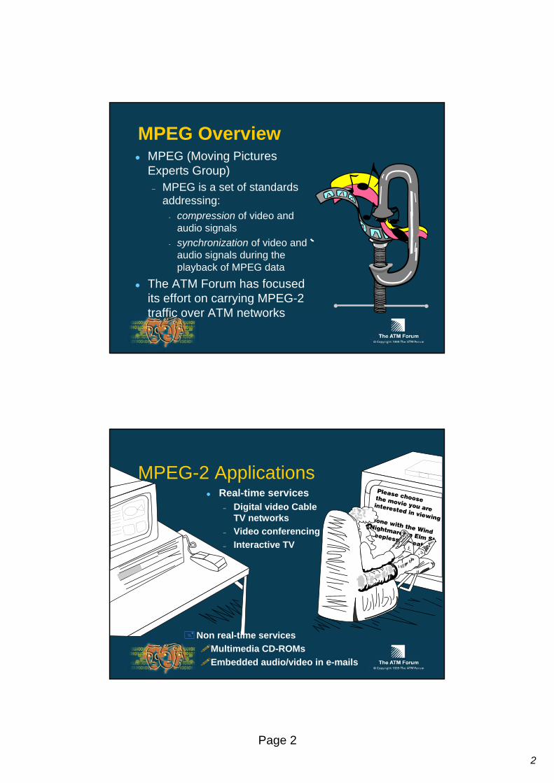
MPEG OverviewMPEG (Moving Pictures Experts Group)
– MPEG is a set of standards addressing:
- compression of video and audio signals
- synchronization of video and audio signals during the playback of MPEG data
The ATM Forum has focused its effort on carrying MPEG-2 traffic over ATM networks
MPEG-2 ApplicationsReal-time services
– Digital video Cable TV networks
– Video conferencing– Interactive TV
Non real-time servicesMultimedia CD-ROMsEmbedded audio/video in e-mails
3
Page 3
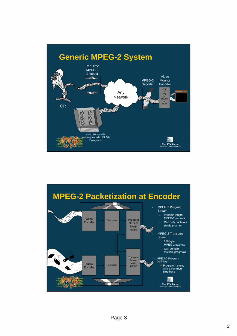
Generic MPEG-2 SystemReal time MPEG-2 Encoder
MPEG-2 Decoder
OR
NTSCor
PALor
SECAMor
RGB
Video Monitor Encoder
AnyNetwork
Video Server with previously encoded MPEG-
2 programs
MPEG-2 Packetization at Encoder
AudioEncoder
Packetizer ProgramStreamMulti-plexer
MPEG-2 Transport Stream
– 188 byteMPEG-2 packets
– Can contain multiple programs
MPEG-2 Program Stream
– Variable length MPEG-2 packets
– Can only contain a single program
TransportStreamMulti-plexerPacketizer
VideoEncoder
MPEG-2 Program Definition
Program = event with a common time-base
B

4
Page 4
MPEG-2: Time-StampsTime-stamps are used to reconstruct the source clock at the decoder and to maintain timing relationships between video and audio information packets
– Time-stamps are inserted into the MPEG-2 packets during the encoding and multiplexing process
AnyNetwork
MPEG-2 Encoder MPEG-2 Decoder
MPEG-2 Stream
MPEG-2 Source Clock inserted into
MPEG-2 Stream
Reconstructed MPEG-2 Source
Clock
B
MPEG-2 Decoder System
Buffer
Buffer
Demuxand
Parse
VideoDecoder
AudioDecoder
Presentation Time Stamp (PTS)
System Time Clock (STC)
Monitor Encoder
Decoder
MPEG-2 Transport Stream
Program Clock Reference (PCR)
ClockRecovery
Coded Video
Coded Audio
A
5
Page 5
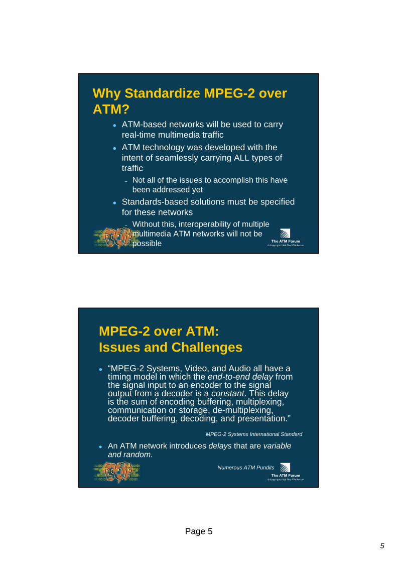
Why Standardize MPEG-2 over ATM?
ATM-based networks will be used to carry real-time multimedia trafficATM technology was developed with the intent of seamlessly carrying ALL types of traffic
– Not all of the issues to accomplish this have been addressed yet
Standards-based solutions must be specified for these networks
– Without this, interoperability of multiple multimedia ATM networks will not be possible
MPEG-2 over ATM:Issues and Challenges
“MPEG-2 Systems, Video, and Audio all have a timing model in which the end-to-end delay from the signal input to an encoder to the signal output from a decoder is a constant. This delay is the sum of encoding buffering, multiplexing, communication or storage, de-multiplexing, decoder buffering, decoding, and presentation.”
An ATM network introduces delays that are variable and random.
MPEG-2 Systems International Standard
Numerous ATM Pundits

6
Page 6
MPEG-2 over ATM:Issues and Challenges
Issues include:– Application specific?– How to recover the MPEG-2 timing?– Use of error detection, correction,
and/or concealment?– Which layer for what functionality?
- Cost of implementation?- Efficiency of transport?
These issues lead to the selection of the AAL to carry MPEG-2 and the signalling parameters needed to ensure the Quality of Service.
Video Audio
MPEG Systems
Network Adaptation Layer
ATM Adaptation Layer
ATM Layer
Physical Layer
A
Application - Specific Quality All issues mentioned affect the quality of the broadcasted video and audioSolution to these issues will depend on the quality required by each application
In broadcast residential video, a higher quality is desired.
In desktop video-conferencing, a lesser degree of quality may be tolerated.

7
Page 7
Due to queuing of ATM cells throughout the network, buffer delay through the ATM layer and AAL layer, and latency across bus interfaces, ATM cells will not arrive at the MPEG-2 decoder with a constant delay.
Cell Delay Variation: Concept
. . .
. . .
. . .
. . .
Arrival times of ATM cells with constant delay
Arrival times of ATM cells that experience Cell Delay Variation
T T T
T (time) is a constant
T1 T2 T3
T1, T2, T3 could all be different
When an ATM cell does not arrive at the expected time, this is known as Cell Delay Variation or “jitter”
MPEG-2 Decoder System
Clock Recovery Circuit
Subtract LPF VCO Counter
PCR
SystemTime Clock
STC Feedback
Buffer
Buffer
Demuxand
Parse
VideoDecoder
AudioDecoder
Presentation Time Stamp (PTS)
System Time Clock (STC)
MonitorEncoder
DecoderMPEG-2 Transport Stream
Program Clock Reference (PCR)
ClockRecovery
Coded Video
Coded Audio
A

8
Page 8
Effect of CDV on MPEG-2: Clock Recovery
MPEG-2 Program Clock References (PCRs) with excessive cell delay variation could cause the MPEG-2 clock recovery circuit (i.e. phase-lock loop) to generate the incorrect MPEG-2 System Clock Frequency and System Time Clock.Incorrect System Time Clock (STC) and System Clock Frequency could result in undesirable quality on the video monitor.
MPEG-2 Clock Recovery Circuit at Decoder
27MHz
MPEG-2 SystemClock Frequency
MPEG-2 SystemTime Clock (STC)
MPEG-2 ProgramClock Reference (PCR)
Subtract LPF VCO Counter
? ?
??
B
Effect of CDV on MPEG-2:Buffer Size?
If buffers are too small
Could lose MPEG-2 packets due to overflow
If buffers are too large
Unnecessary cost in receiver
The magnitude of the maximum cell delay variation determines the size of the buffer needed at the decoder:
1 00
00
0
0 0 011
111
Data Data
Data
9
Page 9
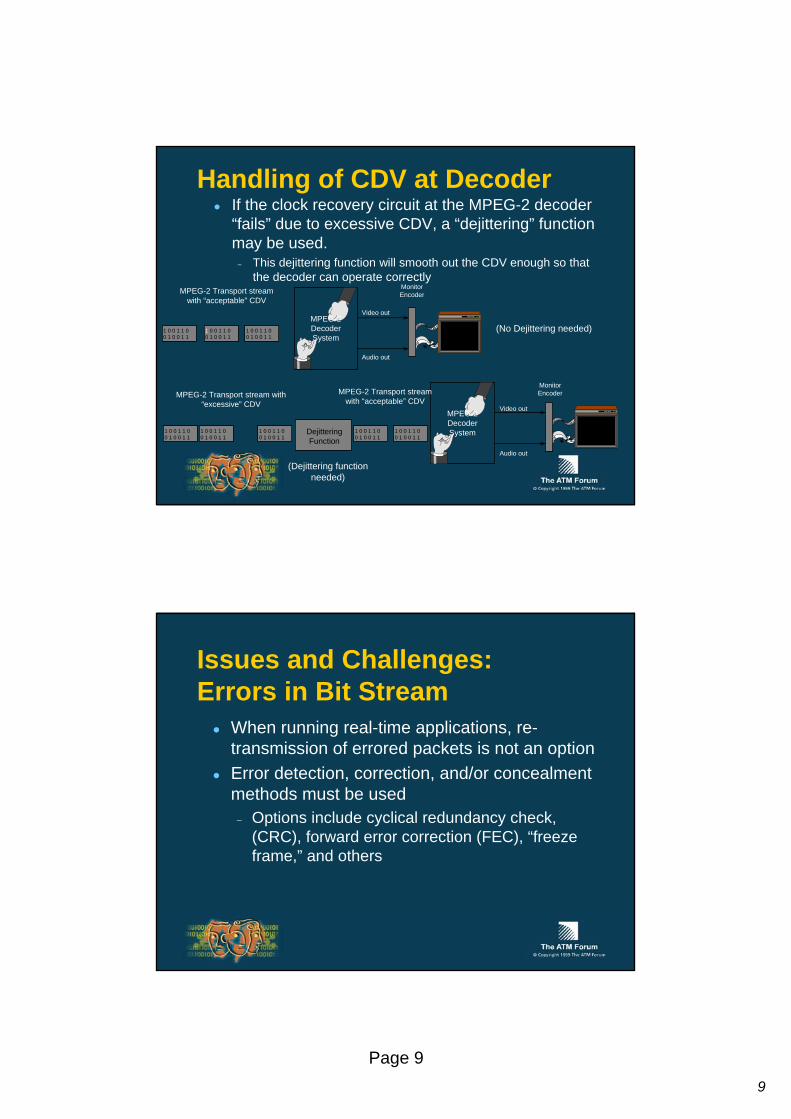
Handling of CDV at DecoderIf the clock recovery circuit at the MPEG-2 decoder “fails” due to excessive CDV, a “dejittering” function may be used.
– This dejittering function will smooth out the CDV enough so that the decoder can operate correctly
Monitor Encoder
Video out
Audio out
MPEG-2 Decoder System
(No Dejittering needed)
Video out
Audio out
MPEG-2 Decoder SystemDejittering
Function
MPEG-2 Transport stream with “acceptable” CDV
MPEG-2 Transport stream with “excessive” CDV
MPEG-2 Transport stream with “acceptable” CDV
(Dejittering function needed)
1 0 0 1 1 00 1 0 0 1 1
1 0 0 1 1 00 1 0 0 1 1
1 0 0 1 1 00 1 0 0 1 1
1 0 0 1 1 00 1 0 0 1 1
1 0 0 1 1 00 1 0 0 1 1
1 0 0 1 1 00 1 0 0 1 1
1 0 0 1 1 00 1 0 0 1 1
1 0 0 1 1 00 1 0 0 1 1
Monitor Encoder
Issues and Challenges:Errors in Bit Stream
When running real-time applications, re-transmission of errored packets is not an optionError detection, correction, and/or concealment methods must be used
– Options include cyclical redundancy check, (CRC), forward error correction (FEC), “freeze frame,” and others

10
Page 10
Which Layer for What Functionality?
AAL Type 1AAL Type 5AAL Type 2
AAL1
Payload
47 bytes
Header functions include:– Lost cell detection
- Used by Adaptive Clock Method– Byte alignment
- Allows channelized circuit emulation, such as channelized DS1
– Time stamp- Used for end-to-end clock synchronization, e.g.
Synchronous Residual Time Stamp method
AAL1 Header
1 byte

11
Page 11
MPEG-2 with AAL1?AAL1’s Synchronous Residual Time Stamp (SRTS) not applicable for timing recovery in MPEG-2 environments
– Common clock needed for SRTS might not be available in MPEG-2 network
AAL1’s optional Forward Error Correction (FEC) capability with interleaving not desirable due to added delay and expense of processingAAL1 support in hardware not as widespread as AAL5 supportAAL1 good choice for backwards compatibility with ISDN networksEfficiency is very good when segmenting MPEG-2 transport stream packets into AAL1 protocol data units (PDUs)
– 1 MPEG-2 transport stream packet (188 bytes) fits exactly into 4 AAL1 PDUs, with no extra padding: PDU efficiency = 97.9%
A
AAL50 - 65535
Data
Pad
0 - 47 22Len
4 bytes
0
bytes
Not drawn to scale
Error detection fields
CRC
. . .
Last cell flag
48 bytes of data per cellUses a PTI bit to indicate last cellOnly one packet at a time on a virtual connection8 byte trailer
48
48
0
1
B
12
Page 12
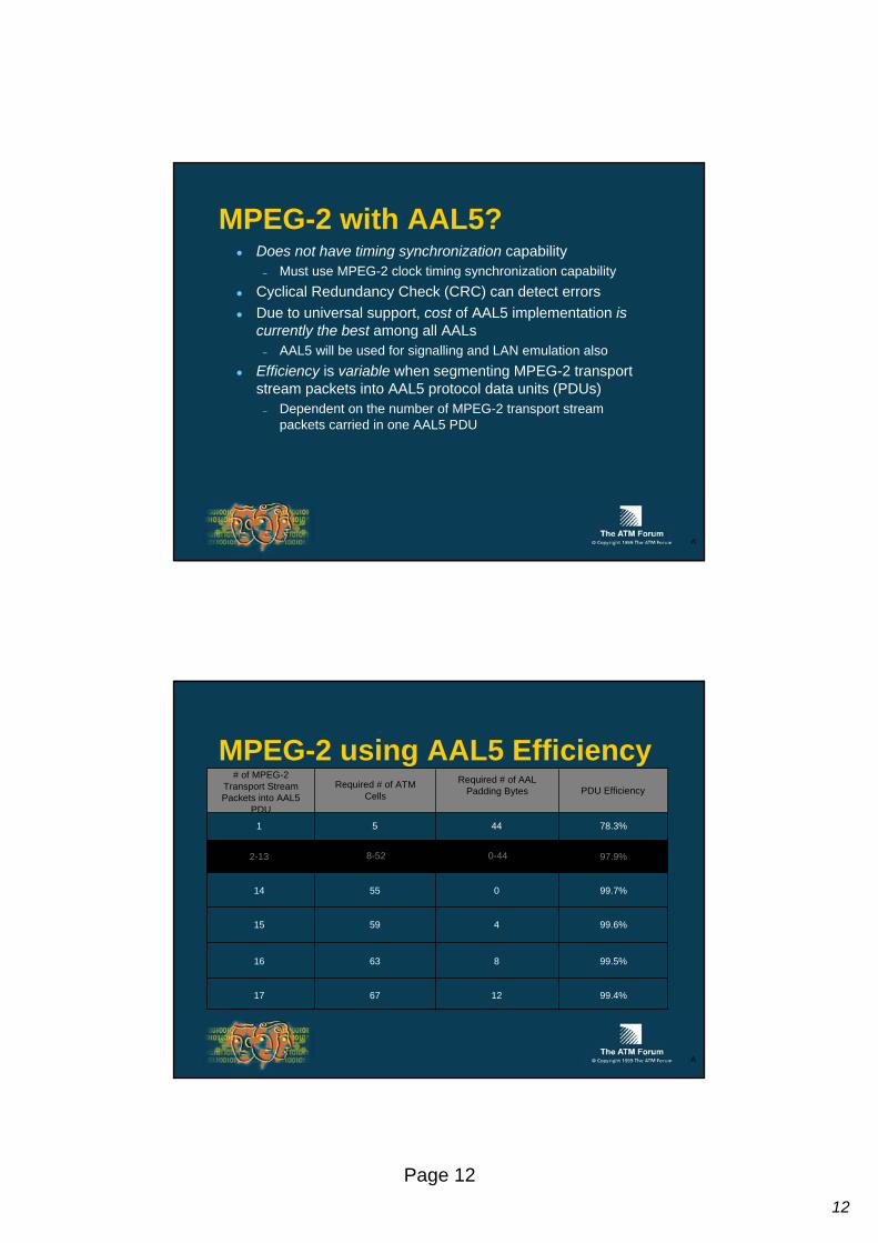
MPEG-2 with AAL5?Does not have timing synchronization capability
– Must use MPEG-2 clock timing synchronization capabilityCyclical Redundancy Check (CRC) can detect errorsDue to universal support, cost of AAL5 implementation is currently the best among all AALs
– AAL5 will be used for signalling and LAN emulation alsoEfficiency is variable when segmenting MPEG-2 transport stream packets into AAL5 protocol data units (PDUs)
– Dependent on the number of MPEG-2 transport stream packets carried in one AAL5 PDU
A
MPEG-2 using AAL5 Efficiency# of MPEG-2
Transport Stream Packets into AAL5
PDU
Required # of ATM Cells
Required # of AAL Padding Bytes PDU Efficiency
1
2-13
14
15
16
17
5
8-52
55
59
63
67
44
0
4
8
12
78.3%
97.9%
99.7%
99.6%
99.5%
99.4%
0-44
A

13
Page 13
MPEG-2 with AAL2?Is the place-holder for variable bit-rate video transmissionIs still undefined in international standards bodies
A
ATM Forum Decisions for Phase 1 Prioritization of Applications
needed for first phase of specifications
– Deployment time-frame of MPEG-2 applications?
What type of MPEG-2 streams will ATM carry?
– Transport Stream Packets or Program Stream Packets?
Which AAL to carry MPEG-2 streams?The appropriate signallingparameters and values, which are application dependent, will also need to be specified
Video Audio
MPEG Systems
Network Adaptation Layer
ATM Adaptation Layer
ATM Layer
Physical Layer
A
14
Page 14
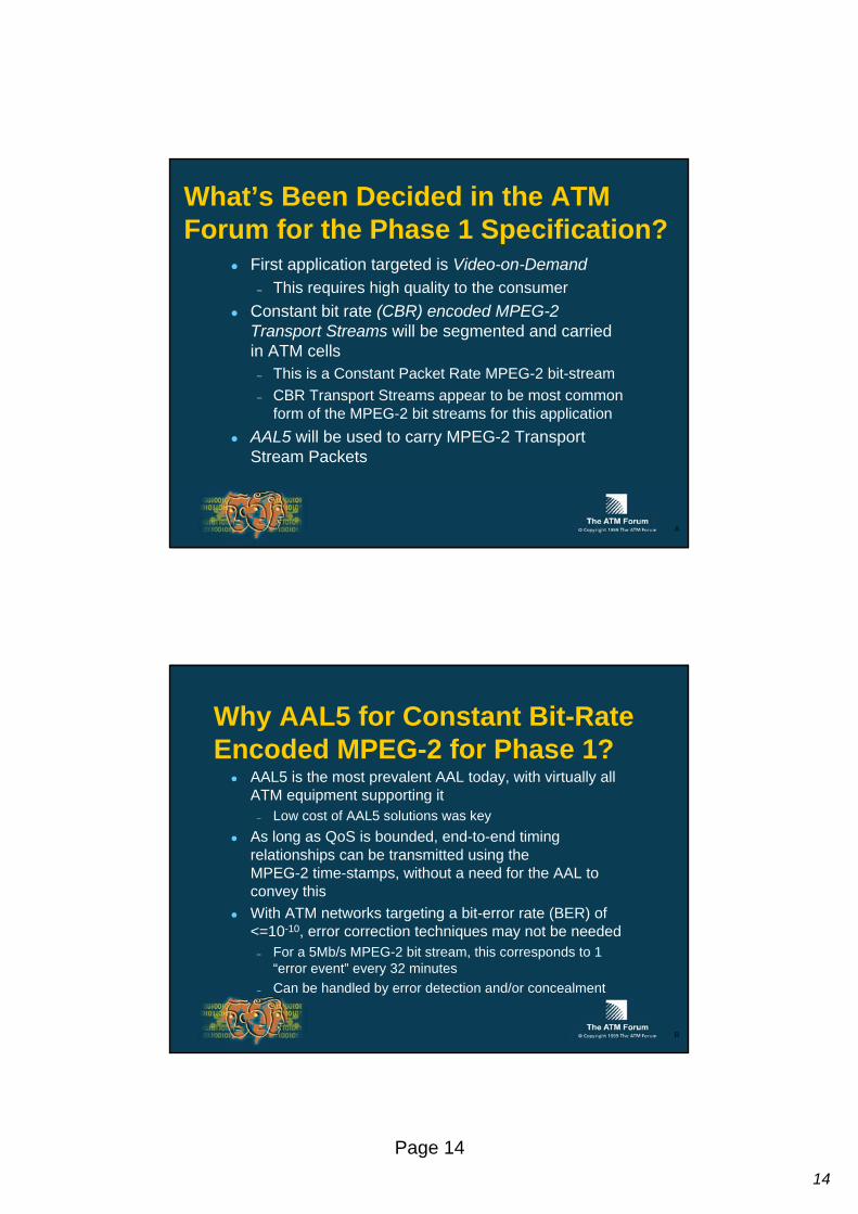
What’s Been Decided in the ATM Forum for the Phase 1 Specification?
First application targeted is Video-on-Demand– This requires high quality to the consumer
Constant bit rate (CBR) encoded MPEG-2 Transport Streams will be segmented and carried in ATM cells
– This is a Constant Packet Rate MPEG-2 bit-stream– CBR Transport Streams appear to be most common
form of the MPEG-2 bit streams for this applicationAAL5 will be used to carry MPEG-2 Transport Stream Packets
A
Why AAL5 for Constant Bit-Rate Encoded MPEG-2 for Phase 1?
AAL5 is the most prevalent AAL today, with virtually all ATM equipment supporting it
– Low cost of AAL5 solutions was keyAs long as QoS is bounded, end-to-end timing relationships can be transmitted using the MPEG-2 time-stamps, without a need for the AAL to convey thisWith ATM networks targeting a bit-error rate (BER) of <=10-10, error correction techniques may not be needed
– For a 5Mb/s MPEG-2 bit stream, this corresponds to 1 “error event” every 32 minutes
– Can be handled by error detection and/or concealment
B
15
Page 15
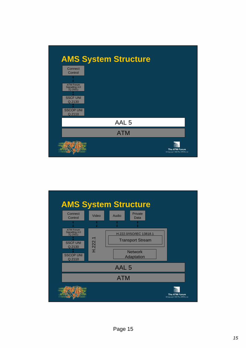
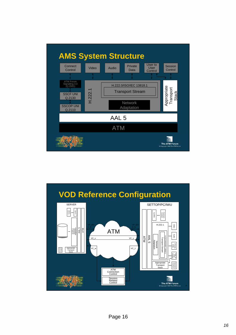
AMS System Structure
ATM
AAL 5
SSCOP UNIQ.2110
ATM ForumSignalling 4.0
(Q.2931)
SSCF UNIQ.2130
ConnectControl
AMS System StructureVideo Audio Private
Data
H.2
22.1
H.222.0/ISO/IEC 13818.1
NetworkAdaptation
Transport Stream
ATM
AAL 5
SSCOP UNIQ.2110
ATM ForumSignalling 4.0
(Q.2931)
SSCF UNIQ.2130
ConnectControl
16
Page 16
AMS System StructureUser to
UserControl
SessionControl
App
ropr
iate
Tran
spor
tS
tack
Video Audio PrivateData
H.2
22.1
H.222.0/ISO/IEC 13818.1
NetworkAdaptation
Transport Stream
ATM
AAL 5
SSCOP UNIQ.2110
ATM ForumSignalling 4.0
(Q.2931)
SSCF UNIQ.2130
ConnectControl
VOD Reference Configuration
ATM
AAL 5
Q.2931
Connect
Control
Video
Audio
PrivateD
ataU
ser toU
serC
ontrolS
essionC
ontrol
H.222.1
H.222.0/IS
O/IE
C 13818.1
Netw
orkAdaptation
Transport Stream
AppropriateTransport
Stack
SETTOP/PC/IWU
ATM
AAL
5
Q.2
931
Con
nect
Con
trol
Sess
ion
Con
trol
H.2
22.1
Net
wor
kA
dapt
atio
n
AppropriateTransport
Stack
SERVER
ATMVP_0/VC_5
VP_0/VC_5
VC_x VC_y
ATMConnection
Control
SessionRelatedControl
VC_w VC_z
A

17
Page 17
Network AdaptationAll equipment conformant with this specification shall support the following network adaptation:
– The MPEG-2 Single Programs Transport Stream (SPTS) packets shall be mapped into the ATM Adaptation Layer Type 5 (AAL5) with a NULL Service Specific Convergence Sublayer.
– One to N MPEG-2 Transport Streams (TS) packets are mapped into an AAL5-SDU.
– For Switched Virtual Circuits (SVCs), the value of N is established via ATM Signalling 4.0 at call setup using the AAL5 Maximum CPCS-SDU negotiation procedure. The AAL5 Maximum CPCS-SDU size that is signalled is N*188 bytes (N being the number of TS packets).
– For Permanent Virtual Circuits (PVCs), the default value on N is two (Maximum CPCS-SDU size = 376 bytes). Other values of N may be selected by bilateral agreement between the settop user and the server via network provisioning.
– In order to insure a base level of interoperability, all equipment shall support N = 2 (CPCS-SDU size = 376 bytes).
A
Network Adaptation: Base Level of N = 2
When an AAL5 PDU contains two 188-octet SPTS Packets, the CPCS-PDU is 384 octets and maps into 8 ATM cells with zero CPCS padding octets.
– An AAL5 CPCS-SDU which has length of 376 octets– An AAL5 trailer of 8 octets
CPCS-PDU Payload (CPCS-SDU) CPCS-PDUTrailer
CPCS-PDU = 8 x 48 octets
376 octets 8 octets
MPEG-2 SPTSPacket i
MPEG-2 SPTSPacket i + l
188 octets 188 octets1st Octet of MPEG SPTS Packet

18
Page 18
Network Adaptation: AAL-5 Action on Corrupted PDUs
When a receiver receives a corrupted AAL5 CPCS-PDU, systems performance MAY be improved by passing the corrupted data, together with an indication that it is corrupted, from the adaptation layer to the demultiplexer layer, rather than simply discarding the data in the adaptation layer.This is an end station implementation option.
ATM Layer Traffic Shaping
Traffic at the egress of the server shall be shaped to conform to the CBR traffic contract negotiated with the ATM networkTraffic shaping is required to occur on a per VC basis

19
Page 19
ATM SignallingThe following signalling parameters are needed by the VoD application and shall be passed through both private and public ATM networks:
– Asymmetrical upstream and downstream bandwidth requirements– QoS Parameters (individual parameters or QoS Classes)– Constant Bit Rate (CBR) operation– Bearer Class = BCOB-X– The AAL5 Maximum CPCS SDU size– ATM Forum VoD Application ID– Generic Identifier Transport I.E. contains a parameter that indicates
the correspondence of the VC to a certain previously establishedrequest carried outside ATM signalling
B
Who Else is Working the Issues?ISO/IEC JTC1/SC29/WG11
– MPEG Systems GroupITU-T SG9
– B-ISDN videoITU-T SG13
– AAL workITU-T SG16
– ITU-T SG16 experts group for video coding and systems in ATM and other environments
Numerous standards bodies– ANSI, ETSI, etc.
Various Forums and Alliances– DAVIC
A

20
Page 20
AMS Phase 1 and Standards
AMS VOD Specification
1.0
ITU Study Group 15
H.222.1
Multimedia Multiplex for ATM
ITU Study Group 9
J.82
Transmission of CBR MPEG-2 over ATM
SummaryA key challenge of transporting MPEG-2 data over ATM networks is Cell Delay VariationThe ATM Forum’s AMS Phase 1 focus was VOD using AAL5 to transport constant bit-rate encoded MPEG-2 transport stream packetsMany standards groups worked together toward this solution
A
21
Page 21
Future WorkAMS Phase 2 will focus on the following activities
– Broadband Multimedia Services encompassing
- Video Conferencing- Interactive Distance Learning- Multimedia Desktop
– VBR-Encoded MPEG-2 over ATM
– Interworking
AcronymsAAL: ATM Adaptation LayerATM: Asynchronous Transfer ModeAMS: Audiovisual Multimedia ServicesBCOB-X: Broadband Connection-Oriented Bearer Service Class XBER: Bit Error RateBHLI: Broadband High-Layer InformationBLLI: Broadband Low-Layer InformationCBR: Constant Bit RateCDV: Cell Delay VariationCD-ROM Compact Disk - Read Only MemoryCRC: Cyclical Redundancy Check
A
22
Page 22
Acronyms (continued)FEC: Forward Error CorrectionI-CDV: Instantaneous Cell Delay VariationISDN: Integrated Services Digital NetworkIWU: Interworking UnitLPF: Low Pass FilterMb/s: Mega-bit per secondMPEG: Moving Pictures Expert GroupMTU: Maximum Transfer UnitPCR: Program Clock ReferencePDU: Protocol Data UnitPES: Packetized Elementary StreamPTS: Presentation Time Stamp
A
Acronyms (continued)PVC: Permanent Virtual CircuitQoS: Quality of ServiceSSCF: Service Specific Convergence FacilitySSCOP: Service Specific Connection-Oriented ProtocolSRTS: Synchronous Residual Time StampSTC: System Time Clock SVC: Switched Virtual CircuitVBR: Variable Bit RateVCO: Voltage Controlled Oscillator
A