audiovisual systems design and coordination components performance standard ds1 public review
DESCRIPTION
Audiovisual Systems Design and Coordination Components Performance Standard DS1 Public ReviewTRANSCRIPT
INFOCOMM 2M: 2009 DS 1
INFOCOMM 2M: 2009 DS 1 Audiovisual Systems Design and Coordination Components InfoComm International Performance Standard Draft Standard 1: 2009-13-10
Abstract A successful professional audiovisual system installation depends on the clear definition and coordination of processes, resources, and responsibilities of the design and installation project teams. A properly documented audiovisual system provides the information necessary to understand and implement the system goals and project requirements in a logical and efficient manner. The documentation should complement and coordinate related architectural, engineering, and construction documentation. This standard outlines a consistent set of the standard tasks, responsibilities, and deliverables required for professional audiovisual systems design and construction.
Keywords Audiovisual, AV system, AV design, AV documentation, AV infrastructure, MasterFormat™, construction documentation, best practice, AV installation, InfoComm
Disclaimer The application of this standard is strictly voluntary. InfoComm International recommends its use but does not assume responsibility for misinterpretation or misapplication. InfoComm International does not assume liability for disputes resulting from the non-conformance to this standard. Conformance does not imply certification of a system. This American National Standard may be revised or withdrawn at any time. The procedures of the American National Standards Institute require that action be taken periodically to reaffirm, revise, or withdraw this standard.
Copyright © 2009 by InfoComm International®. This standard may not be reproduced in whole or in part in any form for sale, promotion, or any commercial purpose, or any purpose not falling within the provisions of the U.S. Copyright Act of 1976, without prior written permission of the publisher. For permission, address a request to the Director of Performance Standards, InfoComm International.
INFOCOMM 2M: 2009 DS 1 Draft Standard 1: 2009-13-10
© 2009 by InfoComm International® Page ii
Foreword There are many types, sizes, and complexity levels of audiovisual systems. The user should apply this standard as appropriate to fit the particular project circumstances. Two common approaches are described here, although there are many possible variations in contractual agreements and relationships between the design and construction team. For example:
Consultant-led projects when the monetary value of the audiovisual systems is high, the building design and construction timeframe is long, and/or the installation work must be bid competitively. Independent consultants are persons or firms having neither financial interest in the products specified nor obligations or partnerships with equipment integrators, contractors, manufacturers, and their representatives;
Design-build projects (also known as turnkey projects) when the construction timeframe is accelerated, the installation systems are proprietary, and/or the project does not require competitive bidding. Professional AV integrator firms are in the business of selling, engineering, installing and providing ongoing service and support for a wide variety of audiovisual and related technologies, systems, and equipment. Equipment manufacturers may also provide turnkey systems design, installation, and service. In addition, owners may choose to have audiovisual systems designed and/or built by their in-house staff.
About InfoComm International InfoComm International® is the leading non-profit association serving the professional AV communications industry worldwide. Founded in 1939, the association offers industry expertise and market research serving press and others seeking information about the industry. Through activities that include tradeshows, education, certification, government relations, outreach, and information services, InfoComm promotes the industry and enhances members’ ability to conduct business successfully and competently. InfoComm International is the ANSI Accredited Standards Developer (ASD) dedicated to the dissemination of the knowledge of audiovisual systems performance parameters.
About ANSI The American National Standards Institute, Inc. (ANSI) is the national coordinator of voluntary standards development and the clearinghouse in the United States for information on national and international standards. An American National Standard implies a consensus of those substantially concerned with its scope and provisions. Consensus is established when, in the judgment of the ANSI Board of Standards Review, substantial agreement has been reached by directly and materially affected interests. Substantial agreement means much more than a simple majority, but not necessarily unanimity. Consensus requires that all views and objections be considered and that a concerted effort be made toward their resolution. The use of an American National Standard is completely voluntary. Its existence does not in any respect preclude anyone, whether he or she has approved the standard or not, from manufacturing, marketing, purchasing, or using products, processes, or procedures not conforming to the standard.
InfoComm International Standards Development InfoComm International maintains a Performance Standards Steering Committee which provides oversight to the standards development task groups responsible for specific standards. The Steering Committee reports to the InfoComm International Board of Directors, whose approval is required before standards may be submitted to ANSI.

INFOCOMM 2M: 2009 DS 1 Draft Standard 1: 2009-13-10
© 2009 by InfoComm International® Page iii
InfoComm International Performance Standards Program Developers DESIGN PACKAGE COMPONENTS PERFORMANCE STANDARD TASK GROUP Brian E. Huff, CTS-D, LEED® AP, ISF-C (Moderator) Joy Caspar, CTS Matthew Jackson, CTS-D Ratnesh Javeri, CTS-D John O’Brien Howard Quinton, CTS-D Brad Weber, PE, CTS INFOCOMM INTERNATIONAL PERFORMANCE STANDARDS PLANNING COMMITTEE Richard Derbyshire (Chair) Scott Walker, CTS-D, LEED® AP (Past Chair) Frederick J. Ampel Michael Carter, CTS Joy Caspar, CTS Barry Goldin, CTS Gary Hall, CTS-D, CTS-I Brian E. Huff, CTS-D Matthew Kosel, CTS-D, CTS-I Greg Jeffreys Brian R. Pipe Peter Swanson, CTS INFOCOMM PERFORMANCE STANDARDS STAFF Joseph Bocchiaro III, Ph.D., AStd, CTS-D, CTS-I, ISF-C (Director of the InfoComm Performance
Standards Program) Randal A. Lemke, Ph.D. (Executive Director) Melissa Taggart (Sr. Vice President of Education, Certification and Standards) Ann Brigida, CTS (Director of Education, Certification, and Standards Marketing)

INFOCOMM 2M: 2009 DS 1 Draft Standard 1: 2009-13-10
© 2009 by InfoComm International® Page iv
Table of Contents Abstract ................................................................................................................ i
Keywords.............................................................................................................. i
Disclaimer............................................................................................................. i
Copyright .............................................................................................................. i
Foreword ............................................................................................................. ii
About InfoComm International .......................................................................... ii
About ANSI .......................................................................................................... ii
InfoComm International Standards Development............................................ ii
InfoComm International Performance Standards Program Developers ....... iii
Table of Contents............................................................................................... iv
Table of Contents............................................................................................... iv
1. Scope, Purpose and Application....................................................................1
2. Referenced Publications................................................................................1
3. Definitions ......................................................................................................3
4. Requirements ................................................................................................4
5. Verification ...................................................................................................14
6. Appendix 1: Optional Services.....................................................................24

INFOCOMM 2M: 2009 DS 1 Draft Standard 1: 2009-13-10
© 2009 by InfoComm International® Page 1
1. Scope, Purpose and Application
Purpose The purpose of this standard is to provide a description of the methods, procedures, tasks, and deliverables typically recommended or applied by industry professionals in medium to large-scale commercial audiovisual (AV) systems design and integration projects. The intention of the structure outlined in this Standard is to enable clients and other design and construction team members to assess confidently whether the responsible parties are providing the expected services. Modern AV systems have become increasingly complex and interconnected to other building systems such as network, electrical, HVAC and building automation/energy conservation. In many instances, AV systems provide critical operational functions for the owner, warranting a thoughtful and well-organized approach to commonly accepted planning, design, and integration procedures. In addition, the AV systems design and integration process may span and parallel a lengthy design and construction cycle, including input and review by many key personnel from divergent disciplines, trades, and backgrounds. This standard provides a practical guideline for defining the audiovisual system requirements and a clear accountability structure for the development and execution of the system design components. It provides a consistent reference for the project team from the initial design phase through construction, project completion, and building occupancy.
Exceptions This standard does not attempt to prescribe an approach to any specific type of AV system project, as they are broadly diverse and may vary by size, functional capability, performance level, and/or cost, among others. Rather, this standard is a customizable guide for the AV project team to fit the specific needs of the owner. It provides an outline and description of the activities necessary for an efficient, well-defined project process. Designers should use the outline for reference by the design, engineering, construction, and installation teams to ensure a clearly executed and successful outcome for the system owner, users, and administrators.
2. Referenced Publications
Normative References
The following standards contain provisions that, through reference in this text, constitute provisions of this document. At the time of approval, the editions indicated below were valid. Because standards are periodically revised, users should consult the latest revision approved by the sponsoring Standards Developer Organizations:
a. American National Standards Institute (ANSI)
b. The Construction Specifications Institute (CSI)

INFOCOMM 2M: 2009 DS 1 Draft Standard 1: 2009-13-10
© 2009 by InfoComm International® Page 2
For the purposes of this document, the use of the latest revision of a referenced standard is not mandatory. However, parties to agreements based on this document are encouraged to apply the most recent editions of the standards and publications listed. Information on recent editions is available from the InfoComm Director of Performance Standards, and ANSI.
a. BICSI and InfoComm International, AV Design Reference Manual, First Edition, 2006,
Tampa, FL and Fairfax, VA
b. InfoComm International, 2005, Audiovisual Best Practices, First Edition, Fairfax, VA
Informative References The following publications contain information that supports the design and application of this standard, but are not required provisions of the standard:
a. The American Institute of Architects, various dates, Contract Documents, Washington, D.C.
b. The Associated General Contractors of America, 2004, Project Delivery Systems for Construction, Alexandria, VA
c. The Construction Specifications Institute, 2004, MasterFormat™ 2004 Edition, Alexandria, VA
d. Heinz, John A., PE, and Casault, Richard B., PE, The Building Commissioning Handbook, Second Edition, Building Commissioning Association, 2004, APPA, BCA
e. InfoComm International, (formerly International Communications Industries Association Inc.), 2003, The Basics of Audio and Visual Systems Design, Revised Edition, Fairfax, VA
f. InfoComm International, Audiovisual Systems Project Documentation Sample, 2009, Fairfax, VA
g. InfoComm International, 2009, AV Installation Handbook, Second Edition, Fairfax, VA
h. InfoComm International, 2006, Dashboard for Controls Design Guide for the Creation of Touchpanel Control Interfaces, Fairfax, VA
i. InfoComm International, 2006, Dashboard for Controls Design Reference, Fairfax, VA
j. National Institute of Building Sciences, 2008, United States National CAD Standard, Washington, DC
k. National Society of Professional Engineers, various dates, Contract Documents, Alexandria, VA

INFOCOMM 2M: 2009 DS 1 Draft Standard 1: 2009-13-10
© 2009 by InfoComm International® Page 3
3. Definitions
a. AHJ: Authority having jurisdiction
b. AV infrastructure: The physical building components that make up the pathways, supports, and architectural elements required for audiovisual technical equipment installations.
c. BOM or BOQ: Bill of materials or Bill of Quantities
d. BREEAM (BRE Environmental Assessment Method) is the international environmental assessment method for buildings. It sets the standard for best practice in sustainable design and has become the de facto measure used to describe a building's environmental performance.
e. CSI: The Construction Specifications Institute
f. CTS®, CTS-D, CTS-I: Professional certifications regarding entry-level, Design, and Installation expertise in audiovisual technology from InfoComm International.
g. Environmental sustainability: The effort to create and maintain conditions under which humans and nature can exist in productive harmony, and fulfill the social, economic and other requirements of present and future generations
h. Equipment rack: A centralized housing unit that protects and organizes electronic equipment.
i. LEED® AP: Accreditation from the USGBC (U. S. Green Building Council) for green building professionals who have demonstrated competence in green building practices.
j. OFE: Owner furnished equipment, sometimes known as owner supplied contractor installed (OSCI) (OFCI) or “Free Issue”
k. PMP®: Certification from the Project Management Institute recognizing demonstrated knowledge and skill in leading and directing project teams and in delivering project results within the constraints of schedule, budget and resources.
l. Raceway: An enclosed channel of metal or nonmetallic materials designed expressly for holding wires, cables, or busbars, with additional functions as permitted in applicable code. Raceways include, but are not limited to, rigid metal conduit, rigid non-metallic conduit, intermediate metal conduit, liquid-tight flexible conduit, flexible metallic tubing, flexible metal conduit, electrical nonmetallic tubing, electrical metallic tubing, under floor raceways, cellular concrete floor raceways, cellular metal floor raceways, surface raceways, wireways, duct, and busways (adapted as example from NEC 2008 Handbook).
m. Cable tray: An unenclosed channel of metal or non-metallic materials designed expressly for holding wires, cables, or busbars, with additional functions as permitted by local or national codes. Cable trays and raceways may also be referred to as trunking.
n. RCDD: Registered Communications Distribution Designer: Certification from BICSI (an association that supports the information transport systems industry) identifying candidates who have demonstrated their knowledge in the design, integration, and implementation of information transport systems and related infrastructure components.
o. Technical power: A term used in the audiovisual industry for lines power that exclusively serves an audiovisual system. The exact definition is country and project-dependent.

INFOCOMM 2M: 2009 DS 1 Draft Standard 1: 2009-13-10
© 2009 by InfoComm International® Page 4
4. Requirements Professional AV Infrastructure, System Design, and Construction Documentation Components Criteria
Designers should analyze and define the system budget, performance needs, and functional requirements prior to the ordering and installing of equipment in order to clearly and formally document the owner’s needs and expectations.
Following approval of the functional concept and overall budget, system design may commence. Subsequently, after designers have completed and fully reconciled the design with the documented functional requirements, system engineering, labor deployment and construction can begin.
The following sections outline the tasks that may be included in this process.
I. Project Planning and Coordination Meetings The project contract documents will typically specify the number, length, and location of meetings required throughout the design effort. Meetings can include face-to-face sessions as well as audio, video, or web-based sessions.
II. Program Phase (alternatively, Briefing Phase or Concept Design Phase)
The purpose of the program phase is to discuss, clarify, and document the owner’s needs, concerns, expectations, and constraints to guide the design team in its approach to the functionality and cost of the AV systems.
A. Needs Analysis: This activity addresses the owner’s business processes to assess specific requirements and expectations. This may include discussions regarding available technologies to meet the owner’s needs and a review of systems and infrastructure proposed to support the project goals. Components of this analysis may include: 1. Interviews with end-users, facilities managers, etc. 2. Surveys of existing facilities 3. Inventories of existing equipment 4. Discovery of additional project requirements, such as sustainable building guidelines
B. Program Report: Also known as the AV Narrative or Discovery Phase Report, the Return
Brief, or the Concept Design Report, this document describes the client’s specific needs, system purpose and functionality, and the designer’s best estimate of probable cost, in a non-technical format for review and approval by the owner. The report follows a Needs Analysis phase addressing the owner’s business processes, which assesses specific requirements and expectations. This may include discussions regarding available technologies to meet the owner’s needs and a review of systems and infrastructure proposed to support the project goals. User reviews and comments on the AV program may warrant revisions and updates to the program report. Components include: 1. Executive Summary: This section provides an overview of the project, project
programming process, systems, special issues, and overall budget. 2. Space Planning: This section provides advice to the design team, where necessary,
as to any special requirements of the audiovisual systems. This may include

INFOCOMM 2M: 2009 DS 1 Draft Standard 1: 2009-13-10
© 2009 by InfoComm International® Page 5
equipment closets, projection rooms, observation rooms, dressing rooms, headend rooms, etc.
3. Systems Descriptions: This section is a non-technical description of the owner’s desired functionality for each system. This section may include AV sketches, drawings, diagrams, photos, product data, and other graphics to exemplify the capabilities of the proposed systems.
4. Infrastructure Considerations: This section includes a description of the electrical, voice, data, mechanical, lighting, acoustic, structural, and architectural infrastructure needed to support the audiovisual systems.
5. Audiovisual Budgets: This section outlines the Probable Costs to procure, install and commission the proposed AV systems, as well as any Additional Costs such as taxes, markups, and contingencies.
III. Design Phase
The purpose of these activities and their associated documents is to identify the functional requirements and design intent for the audiovisual systems. These documents should reference any work required by other trades to complete the AV design. Coordination of these documents with those of other trades is essential.
A. Architectural and Infrastructure Requirements: These documents illustrate the coordination of various aspects of the core, shell, and interior design of the space. Millwork, casework, and furniture, as well as supporting electrical and physical protection systems required to support the audiovisual systems are included.
1. Architectural and Interior Design: This work involves planning for the integration of AV systems in the designated spaces within the project. Items covered may include space planning issues such as, but not limited to:
a) Projection and viewing sightlines and distances b) Lectern locations and presenter ergonomics c) Custom or integrated millwork, furniture, and casework d) Disability access recommendations and codes e) Wall and ceiling height recommendations f) Stage sizes and heights g) Seating tiers and row-to-row distances h) Equipment booths, central control and equipment rooms, service and access. i) Ancillary spaces (breakout rooms, green rooms, dressing rooms, etc.) j) Equipment cooling and ventilation k) Structural and fire rating impacts l) Lighting plan, zones, and control m) Delivery and installation of oversize products (large crated displays, projection
screens and mirrors).
2. Electrical: This work involves coordinating the following AV-related requirements with the project electrical engineer or electrical contractor:
a) National and local codes for high and low voltage installations. b) Electrical power panel (and subpanel) locations, layouts and labeling for AV
supplies. c) Anticipated AV related electrical loads and circuit breaker requirements. d) Surge suppression, clean power and back-up power requirements for AV loads.
(eg., UPS, generators, technical power) e) Receptacles types and locations. f) Requirements for isolated ground or same phase or other project specific
grounding requirements such as technical grounding.

INFOCOMM 2M: 2009 DS 1 Draft Standard 1: 2009-13-10
© 2009 by InfoComm International® Page 6
g) Pathways and capacity for high and low voltage cabling related to AV equipment including interconnects to control and other building systems.
h) Project specific requirements for separation of high and low voltage cable types. i) Specifications, locations and mounting heights for AV related cable boxes and
stubs including floor, wall, ceiling, pull, exterior, millwork and casework. j) Equipment rack isolation and bonding requirements. k) Coordination of AV safety grounds with building safety grounds l) Other AV-Electrical related notes and diagrams m) Local and national review and certification requirements for drawings. Local or
national codes may require a registered electrical engineer to review and stamp the AV-related electrical drawings.
3. Workmanship and Technique: Some jurisdictions require the use of licensed electricians, licensed low voltage cable installers, members of labor organizations, and/or certified professionals for some of the tasks included in an AV contractor's scope. The level of coordination in these circumstances escalates to include many items beyond purely power and related infrastructure concerns. These include but are not limited to:
a) Verification of licensing, permits and/or affiliations with labor organizations b) Expectations for workmanship (i.e., field wiring methods and techniques such as
separation of signals) c) Cable termination standards (i.e., wiring of balanced vs. unbalanced audio)
4. Acoustical: This work involves the coordination of acoustical design criteria for the project and conditions that could directly impact the audio systems designs. The project’s acoustical consultant or designated member of the design team defines the acoustical requirements for the project. The audiovisual systems designer may provide input. The acoustical criteria may include:
a) Architectural acoustics recommendations (e.g., design criteria for
ambient/background noise levels, reverberation time) b) Mechanical systems noise and vibration control recommendations, e.g., isolation
from other noise sources.
5. Information Technology (IT): This work involves the coordination of AV-specific requirements for voice or data services to equipment and equipment rooms. The audiovisual systems designer may provide input to the project team as to the specific location and type of data endpoints, special patching requirements for specialized “hybrid” equipment (non-data use of IT infrastructure), bandwidth requirements, and data prioritization, among other parameters.
B. AV System Documents: These documents detail the qualifications, items, and performance requirements necessary to complete the scope of work for the audiovisual systems.
1. Bid Specifications: Competitive bidding requires written specifications of the audiovisual systems equipment and installation. This standard recommends the insertion of audiovisual specifications into the project construction documents. These documents shall conform to the owner’s requirements and/or CSI MasterFormat™ standards organized as follows:
Part 1 – General: This section communicates to the bidder the basic project structure and relationships between the work covered under the AV specification division(s) and related trade sections. Part 1 – General identifies the technical scope and administrative requirements of the project and typically includes a summary of the project requirements,

INFOCOMM 2M: 2009 DS 1 Draft Standard 1: 2009-13-10
© 2009 by InfoComm International® Page 7
definitions, a list or references to related documents, as well as bid and project submittal requirements. In addition, this section outlines requirements for:
• General conditions • Project schedules • Communications procedures • Incentives and penalty clauses • Terms and payment schedules • Deposits and mobilization fees • Quality assurance • Qualifications • Technical certifications (CTS®, CTS-D, CTS-I, PE, PMP, LEED®
AP, RCDD or other relevant certifications) • Materials handling (e.g., site clean up, disposal, recycling) • Subcontractor/prime contractor relationships • Substitutions • Submittals • Job conditions • Environmental sustainability, energy efficiency, and recycling
Note: Part 1-General should include a suggested or required approach to the design of AV systems with the project’s overall environmental sustainability (LEED, BREEAM) goals, if applicable. This section outlines the redeployment of existing or pre-owned equipment, low-power designations such as ENERGY STAR®, international hazardous substance restrictions such as RoHS and WEEE, AV system or facility power management, and the handling of AV-related packing materials and construction debris. Power offsets, reductions, and savings should be expressed in kilowatt hours (kWh), kilaJoules per second (kJ/s), or British thermal units per hour (Btu/h) as well as tons of carbon dioxide (CO2), and other common raw and hazardous material standard reduction measurements.
• Test reports • Warranty Requirements • Service contracts • Training • Inspections • Drawings of record (As-built drawings)
Part 2 – Products: This section includes a detailed itemization and description of all equipment to be provided as part of the project. The designer may also list the equipment quantities to clarify the project requirements, particularly where products are not installed and indicated on drawings.
Part 3 – Execution: This section describes the installation and performance expectations of the specified equipment. Key elements addressed are the physical installation of equipment, system performance, system testing and user training. Specific subjects that require attention may include but are not limited to:
• Quality of workmanship • Installation standards
o Equipment, plate and panel labeling and labeling techniques
o Wiring and labeling practices • Safety
INFOCOMM 2M: 2009 DS 1 Draft Standard 1: 2009-13-10
© 2009 by InfoComm International® Page 8
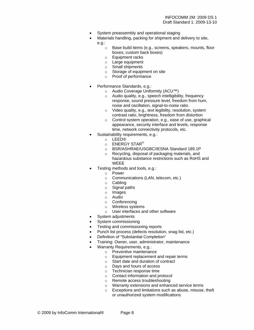
• System preassembly and operational staging • Materials handling, packing for shipment and delivery to site,
e.g.: o Base build items (e.g., screens, speakers, mounts, floor
boxes, custom back boxes) o Equipment racks o Large equipment o Small shipments o Storage of equipment on site o Proof of performance
• Performance Standards, e.g.:
o Audio Coverage Uniformity (ACU™) o Audio quality, e.g., speech intelligibility, frequency
response, sound pressure level, freedom from hum, noise and oscillation, signal-to-noise ratio
o Video quality, e.g., text legibility, resolution, system contrast ratio, brightness, freedom from distortion
o Control system operation, e.g., ease of use, graphical appearance, security interface and levels, response time, network connectivity protocols, etc.
• Sustainability requirements, e.g.: o LEED® o ENERGY STAR® o BSR/ASHRAE/USGBC/IESNA Standard 189.1P o Recycling, disposal of packaging materials, and
hazardous substance restrictions such as RoHS and WEEE
• Testing methods and tools, e.g.: o Power o Communications (LAN, telecom, etc.) o Cabling o Signal paths o Images o Audio o Conferencing o Wireless systems o User interfaces and other software
• System adjustments • System commissioning • Testing and commissioning reports • Punch list process (defects resolution, snag list, etc.) • Definition of “Substantial Completion” • Training: Owner, user, administrator, maintenance • Warranty Requirements, e.g.:
o Preventive maintenance o Equipment replacement and repair terms o Start date and duration of contract o Days and hours of access o Technician response time o Contact information and protocol o Remote access troubleshooting o Warranty extensions and enhanced service terms o Exceptions and limitations such as abuse, misuse, theft
or unauthorized system modifications
INFOCOMM 2M: 2009 DS 1 Draft Standard 1: 2009-13-10
© 2009 by InfoComm International® Page 9
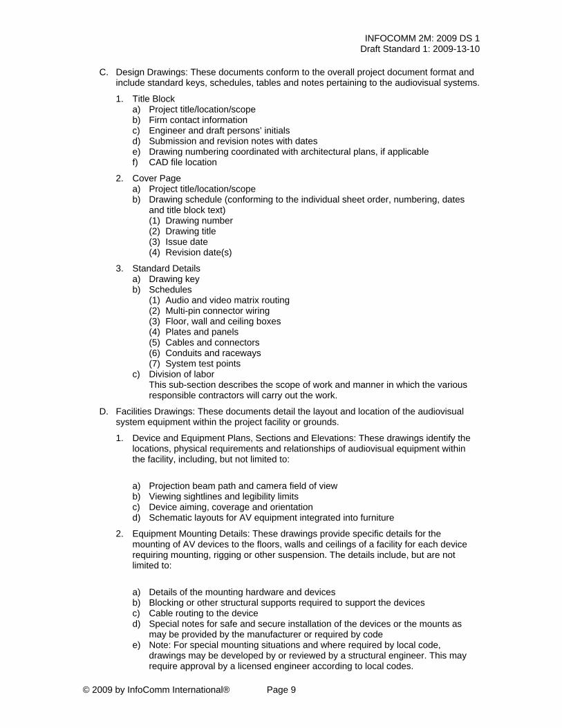
C. Design Drawings: These documents conform to the overall project document format and include standard keys, schedules, tables and notes pertaining to the audiovisual systems.
1. Title Block a) Project title/location/scope b) Firm contact information c) Engineer and draft persons’ initials d) Submission and revision notes with dates e) Drawing numbering coordinated with architectural plans, if applicable f) CAD file location
2. Cover Page a) Project title/location/scope b) Drawing schedule (conforming to the individual sheet order, numbering, dates
and title block text) (1) Drawing number (2) Drawing title (3) Issue date (4) Revision date(s)
3. Standard Details a) Drawing key b) Schedules
(1) Audio and video matrix routing (2) Multi-pin connector wiring (3) Floor, wall and ceiling boxes (4) Plates and panels (5) Cables and connectors (6) Conduits and raceways (7) System test points
c) Division of labor This sub-section describes the scope of work and manner in which the various responsible contractors will carry out the work.
D. Facilities Drawings: These documents detail the layout and location of the audiovisual system equipment within the project facility or grounds.
1. Device and Equipment Plans, Sections and Elevations: These drawings identify the locations, physical requirements and relationships of audiovisual equipment within the facility, including, but not limited to:
a) Projection beam path and camera field of view b) Viewing sightlines and legibility limits c) Device aiming, coverage and orientation d) Schematic layouts for AV equipment integrated into furniture
2. Equipment Mounting Details: These drawings provide specific details for the mounting of AV devices to the floors, walls and ceilings of a facility for each device requiring mounting, rigging or other suspension. The details include, but are not limited to:
a) Details of the mounting hardware and devices b) Blocking or other structural supports required to support the devices c) Cable routing to the device d) Special notes for safe and secure installation of the devices or the mounts as
may be provided by the manufacturer or required by code e) Note: For special mounting situations and where required by local code,
drawings may be developed by or reviewed by a structural engineer. This may require approval by a licensed engineer according to local codes.
INFOCOMM 2M: 2009 DS 1 Draft Standard 1: 2009-13-10
© 2009 by InfoComm International® Page 10
3. Miscellaneous Details: These drawings include any details, drawings or information
necessary for coordination with other building systems and elements to effectively convey the project requirements and design intent for the audiovisual systems. They include, but are not limited to:
a) Equipment racks and enclosures b) Connection plates and receptacles c) Projection screens, switches, and controllers d) Antennas, repeaters, wireless nodes, etc. e) Specialized, floor, wall, and ceiling boxes f) Other items that are attached to or impact the building design or construction
E. System Drawings: These documents detail the audio, video and control signal switching and routing, and other details necessary to convey the complete audiovisual system design.
1. Functional Diagrams: These drawings are commonly known as “Block,” “Flow,” or “Schematic” diagrams. They indicate an overview of the system signal flow in its entirety and illustrate the interconnection of the audio, video, and control subsystems. Functional diagrams also include references to related subsystems and provide the reader with a clarification of the boundaries of the AV scope of work. The diagrams include contractor-provided and owner-furnished equipment, as well as equipment supplied by others. These drawings include compiled or separate drawings for:
a) Audio subsystems b) Antenna distribution systems c) Digital signal processing d) Video subsystems e) Special video subsystems with any interconnect to the main video subsystem
(e.g., matrix routing, CCTV, camera automation, editing) f) Control equipment g) Voice/data systems interface components h) Other diagrams and notes provided for another audiovisual subsystem (e.g.,
lighting, drapes, shades, HVAC, security interfaces)
2. Equipment Rack Elevations: These drawings confirm that proper space allocation, ergonomics, thermal management, weight distribution, and cable management have been considered. For bid and engineering purposes, equipment rack elevations provide a means to estimate the quantities of required patch panels, bulkheads, interconnect cables, patch cables, equipment rack accessories, and other hardware, necessary for a professional installation.
3. Specialized Plates and Panels: These drawings detail the information for all plates
and panels, including size, connector arrangements, types of signals, labeling requirements, and any special integration or installation requirements for that connector.
4. Specialty Connector and Miscellaneous Wiring Diagrams: These drawings illustrate
connectors, pin-outs and wiring used in special circumstances. The majority of connectors, pins and wires in an AV system follow industry standards for termination. Where a connector configuration is used atypically, details for the termination of that connector are provided in the drawing set. The details include an illustration of the connector and its pins as well as a numbering schedule or other labeling of the pins and specific coordination of the pins to individual wires.

INFOCOMM 2M: 2009 DS 1 Draft Standard 1: 2009-13-10
© 2009 by InfoComm International® Page 11
5. Custom Configurations and Modifications: Some elements of the AV system design may require internal modification or special configuration of devices to achieve the intended function in the system. This may include the setting of dip switches, installation of internal jumpers, and similar. In all of these cases details of the special requirements and settings are provided in the drawings to ensure the readers understanding of the requirements and their impact on functionality.
6. Patch Panel Layouts And Labeling: These details serve to clarify the number and
types of panels (by signal) as well as the number of connections per panel. The patch panel layout should be consistent and labeled with the signal type.
F. Custom Application Documentation: These documents convey information necessary to illustrate additional requirements for the configuration of software, hardware, and other programmable equipment and subsystems.
1. Digital Signal Processor (DSP): This documentation describes in detail the necessary
software-configurable audio and video routing, processing and user presets necessary to meet the system functional requirements.
2. User Interface: The section includes a visual or written description illustrating the
logical sequence of the user interface. This may include a GUI layout and/or button-by-button description. The documentation may also outline the requirements and best practices to ensure that programmers have a firm understanding of the AV control system design and scope requirements. These requirements generally include:
a) Contractual guidelines such as payment terms and warranty, definition of scope,
support and documentation, license agreements, and intellectual property rights b) Project management guidelines designed to establish a list of tasks and
deliverables such as process flow, scheduling, testing and debugging, code installation, onsite and remote support, and system commissioning
c) Data storage, including the requirements for provider backup and archiving to protect the integrity and availability of files for future use
3. Asset Management and Scheduling Systems: This documentation includes information regarding the management or scheduling of the AV system via a data network. It may include a network diagram, software requirements, administrative assets, and other system components. This section also includes details about inter-system connectivity, user interface layouts, timing, sequencing or automation of the AV systems.
IV. Construction Phase
A. Construction Drawings: Construction drawings, provided in PDF or other unalterable document format, should include sufficient detail to convey the physical configuration of the AV systems to the installation team. These drawings are also known as Submittal Drawings, Workshop Drawings, or Shop Drawings when provided for review as part of a consultant-led project. Suggested components include, but are not limited to:
1. Title Block a) Project title/location/scope b) Firm contact information c) Engineer and draft person’s initials d) Submission and revision notes with dates e) Drawing numbering coordinated with architectural plans, if applicable f) CAD file location

INFOCOMM 2M: 2009 DS 1 Draft Standard 1: 2009-13-10
© 2009 by InfoComm International® Page 12
2. Cover Page a) Project title/location/scope b) Drawing schedule (conforming to the individual sheet order and information)
(1) Drawing number (2) Drawing title (3) Issue date (4) Revision date(s)
3. Standard Details a) Drawing key b) Schedules
(1) Audio and video matrix routing (2) Multi-pin connector wiring (3) Floor, wall and ceiling boxes (4) Plates and panels (5) Cables and connectors (6) Conduits, ducts, and raceways (7) System test points
c) Division of Labor This sub-section describes the scope of work and manner in which the various responsible contractors will carry out the work.
B. Facilities Drawings: The Construction Facilities Drawings reflect the details provided in the Design Phase Drawings and include any new, additional or construction details for the project.
1. Device and Equipment Plans, Sections and Elevations: These drawings identify the locations, physical requirements and relationships of audiovisual equipment within the facility, to scale where applicable, including exact: a) Projector and camera locations b) Device aiming, coverage and orientation c) Integration of AV equipment into furniture d) Labeling of device type, manufacturer, and model
C. System Drawings: Systems Drawings for Construction/Fabrication include all of the information in the design documents with additional information required to complete fabrication and installation of the audiovisual system.
1. Functional Diagrams: These drawings include all of the information in the design
documents with the following additions: a) Each device block/symbol labeled by manufacturer and model number b) Labeling or graphics indicating the gender, and exact connector type used on
each device c) Each connector and wire clearly labeled indicating type and/or manufacturer part
number d) Wire numbers corresponding to the schedules and adhesive labels attached to
each end of all wires including power cords, proprietary cables, etc. e) Any additional information required to instruct the field technicians in the proper
installation, wiring, and configuration of the systems equipment f) Other diagrams and notes as appropriate
2. Equipment Rack Elevation Diagrams: These drawings and documentation include
and clearly indicate the following (as applicable): a) Front view with the location of each piece of front mounted equipment indicated
in Rack Units (RUs). The count is illustrated from the bottom of the equipment rack with the slot count on the left side.
b) Manufacturer and model number of each piece of equipment.
INFOCOMM 2M: 2009 DS 1 Draft Standard 1: 2009-13-10
© 2009 by InfoComm International® Page 13
c) Identification for each piece of equipment in the equipment rack drawing matching the identification physically attached to all equipment.
d) Side views for locations of internal mounted equipment (e.g., power strips, power supplies, RF splitters, satellite multi-switches, power sequencers).
e) Cable entrance location notes
3. Other Details: These drawings and documentation include the following (as applicable): a) Verification of loudspeaker, projector, and other equipment mounting and aiming
details b) Specialized plate, panel and connector details, including dimensioned engraving
and punching instructions c) Exact patch panel layouts and labeling strip text d) Connector and miscellaneous wiring diagrams, as applicable e) Custom remote control and keypad labeling text
D. Reference Documentation: This documentation clarifies details and settings of each
device that requires specific programming or configuration for its functionality in the system. Examples include:
a) Matrix routing and preset configuration tables b) Digital signal processing configuration details including virtual devices deployed,
matrix schedules, settings, levels, and presets c) Wireless microphone transmission frequencies d) Control equipment e) IT integration information including MAC address/IP address schedules,
patchbay schedules as applicable
E. Project Closeout: The project closeout documentation is submitted to the owner at the conclusion of the construction phase.
a) Drawings of record (“As-built” drawings) b) Final software source code c) Final graphics files d) User operations manuals e) Equipment owner’s manuals, warranty cards, etc. f) Warranty Support Statement for system
INFOCOMM 2M: 2009 DS 1 Draft Standard 1: 2009-13-10
© 2009 by InfoComm International® Page 14
5. Verification I. Verification of conformance to this standard must include the delivery of the Audiovisual
System Design and Coordination Components Checklist (below). This serves to verify the following:
A. Documentation of Applicability – An outline that indicates which sections of the standard
are applicable to the project according to contractual agreements, as well as any services not applicable (indicated as N/A).
B. Consideration – Written verification that the service provider(s) have read and understand this standard, and agree to be referred to as the Responsible Party for the applicable sections.
C. Completion – Written verification that the service provider(s) have completed the approved services, indicated by the party authorized to sign as Accepted By.
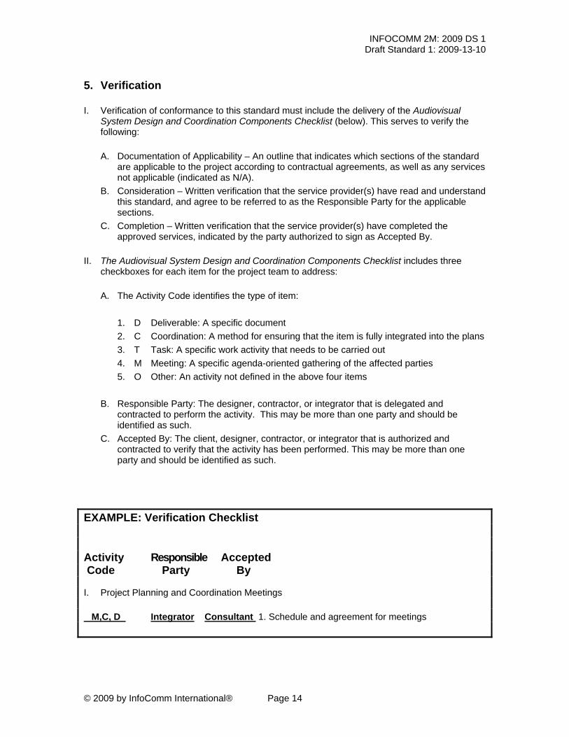
II. The Audiovisual System Design and Coordination Components Checklist includes three
checkboxes for each item for the project team to address:
A. The Activity Code identifies the type of item:
1. D Deliverable: A specific document 2. C Coordination: A method for ensuring that the item is fully integrated into the plans 3. T Task: A specific work activity that needs to be carried out 4. M Meeting: A specific agenda-oriented gathering of the affected parties 5. O Other: An activity not defined in the above four items
B. Responsible Party: The designer, contractor, or integrator that is delegated and contracted to perform the activity. This may be more than one party and should be identified as such.
C. Accepted By: The client, designer, contractor, or integrator that is authorized and contracted to verify that the activity has been performed. This may be more than one party and should be identified as such.
EXAMPLE: Verification Checklist Activity Responsible Accepted Code Party By I. Project Planning and Coordination Meetings M,C, D Integrator Consultant 1. Schedule and agreement for meetings

INFOCOMM 2M: 2009 DS 1 Draft Standard 1: 2009-13-10
© 2009 by InfoComm International® Page 15
Audiovisual Systems Design and Coordination Components Checklist Project Title ____________________________________ Description ______________________________________ Location ____________________________________ Architect ______________________________________ Designer ____________________________________ Date ______________________________________ Integrator ____________________________________ Client ______________________________________ Activity Codes: Meeting – M Coordination – C Task – T Deliverable – D Other – O Note: There may be more than one activity code on each line Activity Responsible Accepted Code Party By I. Project Planning and Coordination Meetings _______ __________ __________ 1. Schedule and agreement for meetings
II. Program Phase _______ __________ __________ 1. Interviews with end-users, facilities managers, etc.
_______ __________ __________ 2. Surveys of existing facilities
_______ __________ __________ 3. Inventories of existing equipment _______ __________ __________ 4. Discovery of additional project requirements _______ __________ __________ 5. Program Report

INFOCOMM 2M: 2009 DS 1 Draft Standard 1: 2009-13-10
© 2009 by InfoComm International® Page 16
Activity Codes: Meeting – M Coordination – C Task – T Deliverable – D Other – O Activity Responsible Accepted Code Party By III. Design Phase
A. Architectural and Infrastructure Requirements
1. Architectural and Interior Design
_______ __________ __________ 1. Projection and viewing sightlines and distances
_______ __________ __________ 2. Lectern locations and presenter ergonomics
_______ __________ __________ 3. Custom or integrated millwork, furniture, and casework
_______ __________ __________ 4. Disability access recommendations and codes
_______ __________ __________ 5. Wall and ceiling height recommendations
_______ __________ __________ 6. Stage sizes and heights
_______ __________ __________ 7. Seating tiers and row-to-row distances
_______ __________ __________ 8. Equipment booths, central control and equipment rooms, service and access.
_______ __________ __________ 9. Ancillary spaces (breakout rooms, green rooms, dressing rooms, etc.)
_______ __________ __________ 10. Equipment cooling and ventilation
_______ __________ __________ 11. Structural and fire rating impacts
_______ __________ __________ 12. Lighting plan, zones, and control
_______ __________ __________ 13. Delivery and installation of oversize products
2. Electrical
_______ __________ __________ 1. National and local codes for high and low voltage installations.
_______ __________ __________ 2. Electrical power panel (and subpanel) locations, layouts, and labeling for AV supplies.

INFOCOMM 2M: 2009 DS 1 Draft Standard 1: 2009-13-10
© 2009 by InfoComm International® Page 17
Activity Codes: Meeting – M Coordination – C Task – T Deliverable – D Other – O Activity Responsible Accepted Code Party By
_______ __________ __________ 3. Anticipated AV related electrical loads and circuit breaker requirements.
_______ __________ __________ 4, Surge suppression, clean power and back-up power requirements for AV loads. (UPS, generators)
_______ __________ __________ 5. Receptacles types and locations.
_______ __________ __________ 6. Requirements for isolated ground or same phase or other project specific grounding requirements.
_______ __________ __________ 7. Pathways and capacity for high and low voltage cabling related to AV equipment
_______ __________ __________ 8. Project specific requirements for separation of high and low voltage cable types.
_______ __________ __________ 9. Specifications, locations and mounting heights for AV related cable boxes, stubs
_______ __________ __________ 10. Equipment rack isolation and bonding requirements.
_______ __________ __________ 11. Coordination of AV safety grounds with building safety grounds.
_______ __________ __________ 12. Other AV-Electrical related notes and diagrams.
_______ __________ __________ 13. Local and national review and certification requirements for drawings
3. Workmanship and Technique _______ __________ __________ 1. Verification of licensing, permits and/or affiliations with labor organizations.
_______ __________ __________ 2. Expectations for workmanship
_______ __________ __________ 3. Cable termination standards. (i.e., wiring of balanced vs. unbalanced audio)
4. Acoustical _______ __________ __________ 1. Architectural acoustics recommendations
_______ __________ __________ 2. Mechanical systems noise and vibration control recommendations

INFOCOMM 2M: 2009 DS 1 Draft Standard 1: 2009-13-10
© 2009 by InfoComm International® Page 18
Activity Codes: Meeting – M Coordination – C Task – T Deliverable – D Other – O Activity Responsible Accepted Code Party By
5. Information Technology (IT)
_______ __________ __________ 1. Information Technology (IT) recommendations AV System Documents
B. AV System Documents _______ __________ __________ 1. Bid Specifications: Part 1 – General
_______ __________ __________ 2. Bid Specifications: Part 2 – Products
_______ __________ __________ 3. Bid Specifications: Part 3 – Execution
C. Design Drawings
_______ __________ __________ 1.Title Block
_______ __________ __________ 2. Cover Page
_______ __________ __________ 3. Standard Details
D. Facilities Drawings _______ __________ __________ 1. Device and Equipment Plans, Sections and Elevations
_______ __________ __________ 2. Equipment Mounting Details
_______ __________ __________ 3. Miscellaneous Details

INFOCOMM 2M: 2009 DS 1 Draft Standard 1: 2009-13-10
© 2009 by InfoComm International® Page 19
Activity Codes: Meeting – M Coordination – C Task – T Deliverable – D Other – O Activity Responsible Accepted Code Party By
E. System Drawings
1. Functional Diagrams
_______ __________ __________ 1. Functional Diagrams: Audio subsystems
_______ __________ __________ 2. Functional Diagrams: Antenna distribution systems
_______ __________ __________ 3. Functional Diagrams: Digital signal processing
_______ __________ __________ 4. Functional Diagrams: Video subsystems
_______ __________ __________ 5. Functional Diagrams: Special video subsystems with interconnects to the main video subsystem
_______ __________ __________ 6. Functional Diagrams: Control equipment
_______ __________ __________ 7. Functional Diagrams: Voice/data systems interface components
_______ __________ __________ 8. Functional Diagrams: Other diagrams and notes provided for any other audiovisual subsystem
2. Equipment Rack Elevations
_______ __________ __________ 1. Equipment Rack Elevations
3. Specialized Plates and Panels
_______ __________ __________ 1. Specialized Plates and Panels

INFOCOMM 2M: 2009 DS 1 Draft Standard 1: 2009-13-10
© 2009 by InfoComm International® Page 20
Activity Codes: Meeting – M Coordination – C Task – T Deliverable – D Other – O Activity Responsible Accepted Code Party By
4. Specialty Connector and Miscellaneous Wiring Diagrams
_______ __________ __________ 1. Specialty Connector and Miscellaneous Wiring Diagrams
5. Custom Configurations and Modifications
_______ __________ __________ 1. Custom Configurations and Modifications
6. Patch Panel Layouts And Labeling
_______ __________ __________ 1. Patch Panel Layouts And Labeling
F. Custom Application Documentation _______ __________ __________ 1. Digital Signal Processor (DSP)
_______ __________ __________ 2. User Interface
_______ __________ __________ 3. Asset Management and Scheduling Systems
INFOCOMM 2M: 2009 DS 1 Draft Standard 1: 2009-13-10
© 2009 by InfoComm International® Page 21
Activity Codes: Meeting – M Coordination – C Task – T Deliverable – D Other – O Activity Responsible Accepted Code Party By
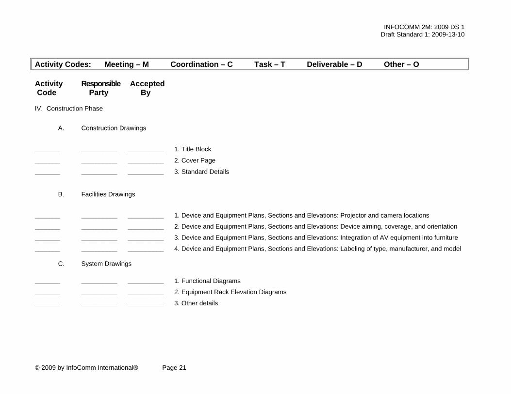
IV. Construction Phase
A. Construction Drawings
_______ __________ __________ 1. Title Block
_______ __________ __________ 2. Cover Page
_______ __________ __________ 3. Standard Details
B. Facilities Drawings
_______ __________ __________ 1. Device and Equipment Plans, Sections and Elevations: Projector and camera locations
_______ __________ __________ 2. Device and Equipment Plans, Sections and Elevations: Device aiming, coverage, and orientation
_______ __________ __________ 3. Device and Equipment Plans, Sections and Elevations: Integration of AV equipment into furniture
_______ __________ __________ 4. Device and Equipment Plans, Sections and Elevations: Labeling of type, manufacturer, and model
C. System Drawings
_______ __________ __________ 1. Functional Diagrams
_______ __________ __________ 2. Equipment Rack Elevation Diagrams
_______ __________ __________ 3. Other details

INFOCOMM 2M: 2009 DS 1 Draft Standard 1: 2009-13-10
© 2009 by InfoComm International® Page 22
Activity Codes: Meeting – M Coordination – C Task – T Deliverable – D Other – O Activity Responsible Accepted Code Party By
D. Reference Documentation
_______ __________ __________ 1. Matrix routing and preset configuration tables
_______ __________ __________ 2. Digital signal processing configuration details
_______ __________ __________ 3. Wireless microphone transmission frequencies
_______ __________ __________ 4. Control Equipment
_______ __________ __________ 5. IT integration information
E. Project Closeout
_______ __________ __________ 1. Drawings of record (As-built drawings)
_______ __________ __________ 2. Final software source code
_______ __________ __________ 3. Final graphics files
_______ __________ __________ 4. User operations manuals
_______ __________ __________ 5. Equipment owner’s manuals, warranty cards, etc.
_______ __________ __________ 6. Warranty Support Statement for system
INFOCOMM 2M: 2009 DS 1 Draft Standard 1: 2009-13-10
© 2009 by InfoComm International® Page 23
Activity Codes: Meeting – M Coordination – C Task – T Deliverable – D Other – O Activity Responsible Accepted Code Party By
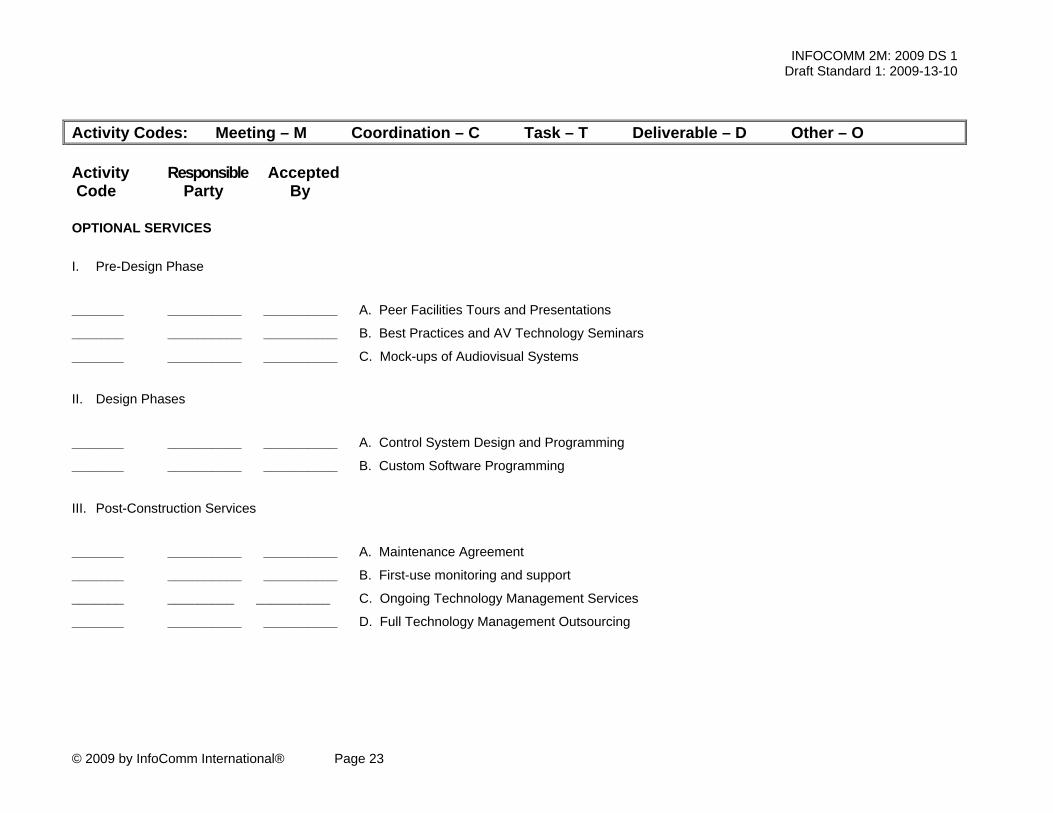
OPTIONAL SERVICES I. Pre-Design Phase
_______ __________ __________ A. Peer Facilities Tours and Presentations
_______ __________ __________ B. Best Practices and AV Technology Seminars
_______ __________ __________ C. Mock-ups of Audiovisual Systems
II. Design Phases
_______ __________ __________ A. Control System Design and Programming
_______ __________ __________ B. Custom Software Programming
III. Post-Construction Services
_______ __________ __________ A. Maintenance Agreement
_______ __________ __________ B. First-use monitoring and support
_______ _________ __________ C. Ongoing Technology Management Services
_______ __________ __________ D. Full Technology Management Outsourcing

INFOCOMM 2M: 2009 DS 1 Draft Standard 1: 2009-13-10
© 2009 by InfoComm International® Page 24
6. Appendix 1: Optional Services I. Pre-Design Phase
A. Peer Facilities Tours and Presentations: The owner and the project design team may decide to benchmark peer facilities prior to beginning a design engagement. This exercise allows project stakeholders to evaluate recently completed facilities similar in scale and scope to their proposed facility. Often two or three facilities will be toured after which the design team may be asked to assemble and present findings from these tours and assess the lessons learned from owners of these peer facilities.
B. Best Practices and AV Technology Seminars: Similar to the peer facility tours noted above, an AV designer may be asked to facilitate general AV technology seminars to apprise project stakeholders of the newest technology solutions and industry best practices.
C. Mock-ups of Audiovisual Systems: The owner and the project design team may decide to create a “mock-up” room that simulates the essential ergonomic, lighting, and acoustic properties of the architectural design. An audiovisual system, whether real or simulated, may be incorporated into this space to verify sightlines, ergonomic features, and other considerations.
II. Design Phases
A. Control System Design and Programming: Control systems represent uniquely challenging aspect to an integrated AV system design. Today's control solutions involve both hardware designs (typically identified in the AV designer’s hardware drawings) and custom programming to automate and simplify system usage as well as related environmental system control (e.g., lights, shades, HVAC systems)
B. Custom software programming is performed during construction by the systems integrator, independent programmer, manufacturer, owner's technical staff, or consultant, and typically includes the following deliverables:
1. Logic flow diagrams: Designers may opt to communicate the
control system's functional requirements through flow diagrams to indicate the sequence of events and logic paths a system should follow.
2. Touch panel layouts: Designers may choose to define the user interface design as part of the system design documentation. These user interface (UI) designs may take the form of simple button panel layouts or may include full iconography and button-by-button descriptions of logic flows.
3. Control Code: Customized programming code is required to display the touch panel layouts in the proper sequence, make the buttons function as required and instruct the control system to activate the various devices in the AV system and environment behave as desired. Control code is typically created during the system integration phase; however, some projects may require prototypical control code for system mock ups during the design phase or early in the systems integration phase to allow an owner to sign off on the user interface.

INFOCOMM 2M: 2009 DS 1 Draft Standard 1: 2009-13-10
© 2009 by InfoComm International® Page 25
III. Post-Construction Services
A. Maintenance Agreement: For some systems and clients, maintenance services may be desirable to ensure the continuous quality operation of the system. Under contract, a systems integrator may provide inspection, adjustment, cleaning of equipment and systems, etc. Inspectors may identify worn parts, updates or enhancements that may require additional compensation.
B. First-use monitoring and support: For some systems and clients, it is advantageous to have the systems integrator or design consultant present at the first or early events in the venue to operate the equipment and/or advise the operator. This may be desirable for a variety of reasons, such as the inability to train operators fully due to time constraints, temporary equipment in an unfinished system, the necessity to instill confidence in the system, etc.
C. Ongoing Technology Management Services: In some cases, an owner requires additional technical support in the post-construction phase that does not fit the traditional service model. Examples of ongoing support needs could include:
1. Post-construction commissioning services not just at project
completion but many months after occupancy 2. Additional training sessions for new users and technicians over
time 3. Consultative services related to enterprise-level rollouts of new
technology 4. Software/firmware upgrades over time 5. Other initiatives related to adapting/connecting a new project to
other facilities or groups
D. Full Technology Management Outsourcing: For some clients it may make sense, both financially and organizationally, to pursue a full outsourcing arrangement for day-to-day AV operations. Similar to an IT outsourcing solution, this arrangement allows an owner to focus on their core business while outsourcing services that are not core. Duties could include in-room AV services, videoconference/bridge monitoring, video production/post-production services, and other related duties.