aufnehmer sensors - mltfinland.fi · aufnehmer sensors katalog catalog. condition monitoring...
TRANSCRIPT

Edition 04/2008VIB 9.663-1DG
PRÜFTECHNIK
Condition Monitoring
eMail: [email protected]
AufnehmerSensors
KatalogCatalog


Condition MonitoringZustandsüberwachung
Handheld Instruments
A 1 VIBROTIP® / VIBTOOL®
A 2 VIBROCORD®
A 3 VIBROSPECT® FFT
A 4 VIBSCANNER® / smartSCANNER™
A 5 VIBXPERT®
Online Systems
B 1 VIBREX®
B 2 VIBRONET® Master
B 3 VIBRONET® Signalmaster
B 4 VIBROWEB® / VIBROWEB® XP
B 5 VIBNODE®
Accessories
C 1 Sensors
C 2 Cables
C 3 VIBRONET® Accessories
C 4 PC Software
Product Catalog

ProduktblattProduct summary
©PR
ÜFT
ECH
NIK
Con
diti
on M
onit
orin
g | O
skar
-Mes
ster
-Str
. 19
-21
| 857
37 Is
man
ing,
Ger
man
y | V
ersi
on:
04.2
008
VIB 3.100 Klebeset, 2x 100g C1.27VIB 3.306 Reflexfolie, 10mm breit C 1.38VIB 3.411 Adapter, Kontermutter, M8-M8 C1.19VIB 3.412 Adapter, Kontermutter, M8-M10 C1.19VIB 3.413 Adapter, Kontermutter, M8-M12 C1.19VIB 3.414 -, UNC 5/16 - UNC 5/16 C1.19VIB 3.415 -, UNC 5/16 - UNC 3/8- 16 C1.19VIB 3.416 -, UNC 5/16 - UNC 1/2 -13 C1.19VIB 3.417 Schraubadapter, Minisensor C1.22VIB 3.418 Klebeadapter, UNF 1/4, Minisens. C1.21VIB 3.420 Magnetadapter, gewölbt, M5 C1.20VIB 3.422 Magnetadapter, plan, M5 C1.20VIB 3.423 Magnetadapter, plan, UNF 1/4 C1.20VIB 3.430 Klebeadapter auf M5 C1.21VIB 3.431 Klebeadapter auf M8 C1.21VIB 3.432 Klebeadapter auf UNC 5/16 C1.21VIB 3.433 Klebeadapter auf UNF 1/4 C1.21VIB 3.435 Schraubadapter M5 120°- M5 C1.22VIB 3.436 Schraubadapter M5 - M6 C1.22VIB 3.437 Schraubadapter UNF 1/4 - M8 90° C1.22VIB 3.438 Schraubadapter UNF 1/4-M8 flach C1.22VIB 3.439 Schraubadapter UNF 1/4-M5 flach C1.22VIB 3.440 Schraubadapter, M8 - M5 C1.22VIB 3.441 Schraubadapter, UNC 5/16 - M5 C1.22VIB 3.450 Tastspitze, M5 plan C1.23VIB 3.474 Schraubadapter, M8 - M16 C1.22VIB 3.475 Schraubadapter, M8 - M20 C1.22VIB 3.480 Schraubadapter UNF 1/4 - M8 C1.22
Begrenzungseinrichtung für EX-Bereich:VIB 3.550 -, für LineDrive-Sensoren C 1.10
VIB 4.330 Triggerstativ C 1.39
VIB 5.73... VIBROTECTOR C1.12VIB 5.740-X Kabel, gerader Stecker C1.12VIB 5.741-X Kabel, Winkelstecker C1.12VIB 5.991DIS Wegaufnehmer (10mm) C1.41VIB 5.992BA Induktiver Drehzahlsensor C1.36VIB 5.992ENC Induktiver Näherungsschalter C1.40VIB 5.993MIC Mikrophon C1.44VIB 6.102R Industrieaufnehmer, Klebesockel C1.2VIB 6.107 -, für Langsamläufer, Klebesockel C1.6VIB 6.122R Industrieaufnehmer, M8 Gewinde C1.3VIB 6.125R -, Hochtemperaturversion, M8 C1.3bVIB 6.127 -, für Langsamläufer, M8 C1.7VIB 6.129-IP -, für Langsaml., Hochtemp.,M8 C1.7bVIB 6.132R Industrieaufnehmer, UNC 5/16 C1.4VIB 6.135R -, Hochtemperatur, UNC 5/16 C1.4bVIB 6.137 -, für Langsamläufer, UNC 5/16 C1.8VIB 6.142 Mobiler Industrieaufnehmer, M5 C1.13VIB 6.147 -, für Langsamläufer, M5 C1.14VIB 6.172 ICP-Beschl.aufnehmer, Mil C1.11cVIB 6.195 Beschleunigungsaufnehmer für
langsamlaufende Maschinen C1.9VIB 6.202/3 Mini-Beschleunigungsaufnehmer C1.5VIB 6.210 ICP-Beschl. aufnehmer, M12 C1.11
VIB 3.100 Bonding kit, 2x 100g C1.29VIB 3.306 Reflective tape C 1.38VIB 3.411 Adapter w. locking nut, M8-M8 C1.19VIB 3.412 Adapter w. locking nut, M8 - M10C1.19VIB 3.413 Adapter w. locking nut, M8 - M12C1.19VIB 3.414 -, UNC 5/16 - UNC 5/16 C1.19VIB 3.415 -, UNC 5/16 - UNC 3/8- 16 C1.19VIB 3.416 -, UNC 5/16 - UNC 1/2 -13 C1.19VIB 3.417 Screwed adapter, mini sensor C1.22VIB 3.418 Bonded adapter, UNF 1/4, mini s. C1.21VIB 3.420 Magnetic adapter, M5, curved C1.20VIB 3.422 Magnetic adapter, M5,flat C1.20VIB 3.423 Magnetic adapter, UNF 1/4,flat C1.20VIB 3.430 Bonded adapter to M5 C1.21VIB 3.431 Bonded adapter to M8 C1.21VIB 3.432 Bonded adapter to UNC 5/16 C1.21VIB 3.433 Bonded adapter to UNF 1/4 C1.21VIB 3.435 Screwed adapter, M5 120° - M5 C1.22VIB 3.436 Screwed adapter, M5 - M6 C1.22VIB 3.437 Screwed adapter, UNF1/4- M8 90°C1.22VIB 3.438 Screwed adapter, UNF1/4- M8 flat C1.22VIB 3.439 Screwed adapter, UNF1/4- M5 flat C1.22VIB 3.440 Screwed adapter, M8 - M5 C1.22VIB 3.441 Screwed adapter, UNC 5/16 - M5 C1.22VIB 3.450 Probe tip, M5 flat C1.23VIB 3.474 Screwed adapter, M8 - M16 C1.22VIB 3.475 Screwed adapter, M8 - M20 C1.22VIB 3.480 Screwed adapter, UNF1/4- M8 C1.22
Limiting device for intrinsic safe areasVIB 3.550 -, for LineDrive sensors C 1.10
VIB 4.330 Trigger bracket C 1.39
VIB 5.73... VIBROTECTOR C1.12VIB 5.740-X Cable with straight plug C1.12VIB 5.741-X Cable with angled plug C1.12VIB 5.991DIS Displacement tranducer (10mm) C1.41VIB 5.992BA RPM sensor, inductive C1.36VIB 5.992ENC Inductive proximity switch C1.40VIB 5.993MIC Microphone C1.44VIB 6.102R Ind. accelerometer, bonded ver. C1.2VIB 6.107 -, low-speed mach., bonded ver. C1.6VIB 6.122R Ind. accelerometer, M8 thread C1.3VIB 6.125R -, high-temperature version, M8 C1.3bVIB 6.127 -, low-speed mach., M8 C1.7VIB 6.129-IP -, low-speed, high-temp., M8 C1.7bVIB 6.132R Ind. accelerometer, UNC 5/16 C1.4VIB 6.135R -, high-temperature, UNC 5/16 C1.4bVIB 6.137 -, for low-speed, UNC 5/16 C1.8VIB 6.142 Mobile ind. accelerometer, M5 C1.13VIB 6.147 -, for low-speed machines, M5 C1.14VIB 6.172 ICP-type accelerometer, Mil con. C1.11cVIB 6.195 Accelerometer for low-speed
machines C1.9VIB 6.202/3 Mini accelerometer C1.5VIB 6.210 ICP-type accelerometer, M12 con. C1.11
Index nach Bestellnummer
Bestellnummer Seite
Index by order number
Order number Page

ProduktblattProduct summary
©PR
ÜFT
ECH
NIK
Con
diti
on M
onit
orin
g | O
skar
-Mes
ster
-Str
. 19
-21
| 857
37 Is
man
ing,
Ger
man
y | V
ersi
on:
04.2
008
Index nach Bestellnummer
Bestellnummer Seite
Index by order number
Order number Page
C 1.0C1.0 ... C1.0a
VIB 6.610 Einbau-Temperaturfühler PT100 C 1.35VIB 6.620 Induktiver Drehzahlsensor C 1.37VIB 6.630 Optischer Triggersensor, aktiv C 1.38VIB 6.640 Näherungssensor, Datensammler C 1.42VIB 6.641 Näherungssensor, Online System C 1.42VIB 6.645 Wegsensor, Online System C 1.43VIB 6.646 Kabel für Wegsensor VIB 6.645 C 1.43VIB 6.760..1 IP 68 Option für Ind.aufnehmer C 1.7dVIB 8.321 Drehzahlsensor C1.37VIB 8.477 Klebehilfe C1.27VIB 8.560 Schwingungskalibrator C1.32VIB 8.563 VIBCODE Codierring C1.18kVIB 8.566 Schutzkappe f. VIBCODE Bolzen C1.18mVIB 8.568 Farbcodierung für Schutzkappe C1.18mVIB 8.571 VIBCODE Messpunkt mit
Kontermutter M8 C1.18fVIB 8.572 -, mit Kontermutter M10 C1.18fVIB 8.573 -, mit Kontermutter M12 C1.18fVIB 8.576 VIBCODE Messpunkt mit
Verlängerung M8 x 55 C1.18dVIB 8.577 -, mit Verlängerung M8x95 C1.18dVIB 8.578 -, mit Verlängerung M8/170 C1.18dVIB 8.580 -, mit Verl. UNC 5/16, 2 1/8" C1.18dVIB 8.581 -, mit Verl. UNC 5/16, 3 3/4" C1.18dVIB 8.582 -, mit Verl. UNC 5/16, 6 5/8" C1.18dVIB 8.586 Verlängerung für
Industrieaufnehmer M8x55 C1.24VIB 8.587 -, M8 x 95 C1.24VIB 8.588 -, M8 x 170 C1.24VIB 8.589 -, M8 x 35 C1.24VIB 8.590 Verlängerung für Industrieaufnehmer
UNC 5/16, 2 1/8" C1.24VIB 8.591 -, UNC 5/16, 3 3/4" C1.24VIB 8.592 -, UNC 5/16, 6 5/8" C1.24VIB 8.594 VIBCODE Messpunkt mit
Kontermutter UNC5/16-18 C1.18fVIB 8.595 -, Kontermutter UNC3/8-16 C1.18fVIB 8.596 -, Kontermutter UNC1/2-13 C1.18fVIB 8.606 TIPTECTOR Handsonde C1.15VIB 8.607-1,5 Magnet-Temperaturfühler C 1.33VIB 8.608 Temperatur-Handtastsonde C 1.34VIB 8.609 TIPTECTOR Verlängerung C1.15aVIB 8.610 Spezialsenker C 1.26VIB 8.618-1,5 TIPTECTOR Kabel / 1,5 Meter C1.15VIB 8.618-5 TIPTECTOR Kabel / 5 Meter C1.15aVIB 8.633 TIPTECTOR Griff C1.15VIB 8.660 VIBCODE Schnellaufnehmer C1.18VIB 8.666R Schnellaufnehmer f. Messbolzen C1.16VIB 8.679SET VIBCODE Messpunkt mit
Bolzen M8, VA1.4571 C1.18bVIB 8.680SET -, Bolzen M8 C1.18bVIB 8.685SET -, Klebebolzen C1.18hVIB 8.689SET -, Bolzen UNC 5/16, VA1.4571 C1.18bVIB 8.690SET -, Bolzen UNC 5/16 C1.18bVIB 8.692 VIBCODE Codierwerkzeug C1.18kVIB 8.693 Gewindebohrer M8 C1.25VIB 8.694 90°-Senker C1.25
VIB 6.610 Temperature probe PT 100 C 1.35VIB 6.620 RPM sensor , inductive C 1.37VIB 6.630 Opt. trigger sensor, active C 1.38VIB 6.640 Proximity sensor, Data collector C 1.42VIB 6.641 Proximity sensor, Online system C 1.42VIB 6.645 Displ. sensor, Online system C 1.43VIB 6.646 Cable for displ. sensor VIB 6.645 C 1.43VIB 6.760..1 IP 68 option for ind.accelerometerC 1.7dVIB 8.321 RPM sensor C 1.37VIB 8.477 Bonding aid C1.27VIB 8.560 Vibration calibrator C1.32VIB 8.563 VIBCODE Code ring C1.18kVIB 8.566 Dustcap for VIBCODE stud C1.18mVIB 8.568 Color coding for dustcap C1.18mVIB 8.571 VIBCODE stud with
M8 locking nut C1.18fVIB 8.572 -, M10 locking nut C1.18fVIB 8.573 -, M12 locking nut C1.18fVIB 8.576 VIBCODE long-stem stud, M8/55 C1.18dVIB 8.577 -, M8/95 C1.18dVIB 8.578 -, M8/170 C1.18dVIB 8.580 -, UNC 5/16, 2 1/8" C1.18dVIB 8.581 -, UNC 5/16, 3 3/4" C1.18dVIB 8.582 -, UNC 5/16, 6 5/8" C1.18dVIB 8.586 Extension post for industrial
accelerometer, M8 x 55 C1.24VIB 8.587 -, M8 x 95 C1.24VIB 8.588 -, M8 x 170 C1.24VIB 8.589 -, M8 x 35 C1.24VIB 8.590 Extension post, UNC 5/16,2 1/8" C1.24VIB 8.591 -, UNC 5/16, 3 3/4" C1.24VIB 8.592 -, UNC 5/16, 6 5/8" C1.24VIB 8.594 VIBCODE stud with
UNC 5/16-18 locking nut C1.18fVIB 8.595 -, UNC3/8-16 locking nut C1.18fVIB 8.596 -, UNC1/2-13 locking nut C1.18fVIB 8.606 TIPTECTOR probe C1.15VIB 8.607-1,5 Magnetic temperature probe C 1.33VIB 8.608 Handheld temperature probe C 1.34VIB 8.609 TIPTECTOR grip extension C1.15aVIB 8.610 Countersink bit C 1.26VIB 8.618-1.5 TIPTECTOR cable / 1.5 meter C1.15VIB 8.618-5 TIPTECTOR cable / 5 meter C1.15aVIB 8.633 TIPTECTOR grip C1.15VIB 8.660 VIBCODE transducer C1.18VIB 8.666R Quick fit transducer
for measurement studs C1.16VIB 8.679SET VIBCODE stud with
M8 thread, VA1.4571 C1.18bVIB 8.680SET -, M8 thread C1.18bVIB 8.685SET -, bonded stud C1.18hVIB 8.689SET -, UNC 5/16 thread, VA1.4571 C1.18bVIB 8.690SET -, UNC 5/16 thread C1.18bVIB 8.692 VIBCODE Encoding tool C1.18kVIB 8.693 M8 thread tap C1.25VIB 8.694 90° countersink bit C1.25VIB 8.696 UNC 5/16 thread tap C1.25

ProduktblattProduct summary
©PR
ÜFT
ECH
NIK
Con
diti
on M
onit
orin
g | O
skar
-Mes
ster
-Str
. 19
-21
| 857
37 Is
man
ing,
Ger
man
y | V
ersi
on:
04.2
008
Index nach Bestellnummer
Bestellnummer Seite
Index by order number
Order number Page
C 1.0aC1.0 ... C1.0a
VIB 8.696 Gewindebohrer UNC 5/16 C1.25VIB 8.737 Magnet für Triggerstativ, M5 C 1.39VIB 8.741 Adapter für Kalibrator, flach C1.32VIB 8.742 Adapter für Kalibrator, M8 C1.32VIB 8.745 Installationsprüfer C1.31VIB 8.747 Adapter f. Masch.schutzsysteme C1.30VIB 8.749 Adapter für Stromvorverstärker C1.28VIB 8.772 Schwingungsadapter M8 - M10 C1.22VIB 8.780 Magnet für Triggerstativ, UNC 10 C 1.39
VIB 32000 Messbolzen, M8x24, vernickelt C1.17bVIB 32010 Messbolzen, M8x24, Edelstahl C1.17bVIB 32200 Messbolzen, M8x113, vernickelt C1.17bVIB 32210 Messbolzen, M8x113, Edelstahl C1.17bVIB 32310 Messbolzen, M8x202, Edelstahl C1.17bVIB 32410 Messbolzen, M8x291, Edelstahl C1.17bVIB 33000A25Messbolzen, geklebt, 25 Stck. C1.17
Begrenzungseinrichtung für EX-Bereich:0 2088 0009 -, für ICP-Sensoren C 1.11g0 2088 0010 -, für VIBROTECTOR C 1.12d
VIB 8.737 Magnet for trigger bracket, M5 C 1.39VIB 8.741 Falt adapter for vib. calibrator C1.32VIB 8.742 -, M8 thread C1.32VIB 8.745 Installation checker C1.31VIB 8.747 Adapter f. mach.protect. system C1.30VIB 8.749 Linedrive signal converter C1.28VIB 8.772 Screwed adapter, M8 - M10 C1.22VIB 8.780 Magnet f. trigger br., UNC10 C 1.39
VIB 32000 Meas. stud, M8x24, nickel-platedC1.17bVIB 32010 Meas. stud, M8x24, st. steel C1.17bVIB 32200 Meas. stud, M8x113, nickel-pl. C1.17bVIB 32210 Meas. stud, M8x113, st. steel C1.17bVIB 32310 Meas. stud, M8x202, st. steel C1.17bVIB 32410 Meas. stud, M8x291, st. steel C1.17bVIB 33000A25Meas. stud, bonded ver., 25 pcs. C1.17
Limiting device for intrinsic safe areas0 2088 0009 -, for ICP sensors C 1.11g0 2088 0010 -, for VIBROTECTOR C 1.12d

ProduktblattProduct summary
©PR
ÜFT
ECH
NIK
Con
diti
on M
onit
orin
g | O
skar
-Mes
ster
-Str
. 19
-21
| 857
37 Is
man
ing,
Ger
man
y | V
ersi
on:
04.2
008
C 1.1
Schwingungsaufnehmermit messbarem VorsprungMit einer neuen Generation universell einsetz-barer Industrie-Schwingungsaufnehmer bie-tet PRÜFTECHNIK AG für jede Anwendung dierichtige Lösung an.
• kaum empfindlich gegen Bodendehnung
• kaum empfindlich gegen Temperaturschwankung
• störungsfreie Übertragung durch die eingebaute ‘Line-Drive’-Stufe (auch mit langen Kabeln)
• unempfindlich gegen Querschwingungen
• hohe Stoßverträglichkeit
• integrierte Resonanzfilter gegen Verstärkerüberladen
• erhöhte Langzeitstabilität durch vorheriges Altern
• auch in EX-Version erhältlich
Der patentierte Tandem-Piezo®
Beschleunigungsaufnehmer
Durch die patentierte Tandem-Anordnungder Piezo-Elemente sind die Aufnehmer nahe-zu unempfindlich gegen Temperatursprüngeund Bodendehneffekte. Durch den unge-wöhnlich großen Linearitätsbereich sind siebeispielsweise auch für Untersuchungen anTurbomaschinen und Getrieben geeignet.Eine deutliche Resonanzüberhöhung bei 36kHz erlaubt es Kaviationssignale in Pumpenund sogar die schwachen Stoßimpulssignalevon Wälzlagern zu messen, die für den Lager-Betriebszustand kennzeichnend sind. Ein inte-
SeismischeMasse
PiezoelektrischeElemente
Boden
New industrial accelerometers:better and cheaperPRÜFTECHNIK AG has introduced its new lineof patented Tandem-Piezo accelerometersthat sets new standards in terms of reliability,versatility, mounting ease and economy.
The unique design practically eliminates tem-perature shock and base strain effects; it alsohandles condition evaluation of turbomachin-ery and gearboxes, antifriction bearings andpump cavitation - all with the same transduc-er, thanks to a wide linear range and adefined shock pulse resonance characteristicat 36 kHz. The built-in current line driveamplifier ensures immunity to ground loopingand extremely low signal loss, even over longtransmission distances, as well as compatibilitywith the entire PRÜFTECHNIK line of hand-
The patented Tandem-Piezo®
accelerometer
• Low base strain sensitivity
• Low sensitivity to temperature transients
• Built-in ‘Line-drive’ amplifier offers unsurpassedimmunity against cable noise and ground loops
• Low transverse sensitivity
• High shock resistance
• Integrated resonance suppression filtersavoids amplifier overloading
• Factory burn-in for high long-term stability
• Intrinsically safe version also available
Base
Seismic mass
Piezoelectricelements
C1.1 ... C1.1k

ProduktblattProduct summary
©PR
ÜFT
ECH
NIK
Con
diti
on M
onit
orin
g | O
skar
-Mes
ster
-Str
. 19
-21
| 857
37 Is
man
ing,
Ger
man
y | V
ersi
on:
04.2
008
C 1.1a
grierter Strom-Linedrive-Verstärker bereitetdas Signal so auf, dass es nahezu verlustfreiüber weite Strecken zur Verarbeitungselektro-nik übertragen werden kann.
Zur Montage der Aufnehmer stehen, je nachGehäusewandstärke, robuste Einschraubge-winde oder Klebesockel zur Auswahl. Der Ka-belanschluß erfolgt über einen TNC-Stecker,der schnell und einfach anzuschließen ist undan engen Stellen als Winkelstück nur 45 mmPlatz benötigt. In rauher industrieller Umge-bung wird die Kabelverbindung mit einerGummimanschette (IP 67), bei Unterwasser-installation mit einem Formschrumpfteil (IP 68)hermetisch abgedichtet. Trotz ihres technischaufwendigen Tandem-Piezo®-Designs, sinddiese Aufnehmer herkömmlichen Kompressi-onsaufnehmern preislich überlegen.
held meters, FFT analyzers and online or re-mote condition monitoring equipment.
And the new Tandem-Piezo transducer familynot only costs far less than shear designs, butcuts installation expense as well: economicalstandard TNC fittings mount quickly and areavailable with flexible caps (silicone-free, ifdesired) for extra protection. Laser-weldedand laser-marked, the hermetically sealedhousings withstand even the harshest industri-al surroundings. Angled plugs require only 45mm / 1 13/16" mounting clearance height;besides standard stud mounting, a revolution-ary bonded arrangement is ideal for mountingon thin-profile bearing housings. A self-threading pin holds the accelerometer in placeusing only a small pilot hole while the bondingcompound sets to a final hardness comparableto that of steel.
C1.1 ... C1.1k

ProduktblattProduct summary
©PR
ÜFT
ECH
NIK
Con
diti
on M
onit
orin
g | O
skar
-Mes
ster
-Str
. 19
-21
| 857
37 Is
man
ing,
Ger
man
y | V
ersi
on:
04.2
008
C 1.1bC1.1 ... C1.1k
Ind
ust
rieau
fneh
mer
für
Sch
win
gb
esc
hle
un
igu
ng
zu
r p
erm
an
en
ten
Mo
nta
ge
An
wen
du
ng
(Fr
equ
enzb
erei
ch)
Mo
nta
ge
Bes
on
der
e U
mg
ebu
ng
Typ1
Seite
Stan
dard
Lang
sam
lauf
ende
Mas
ch.
Sehr
lang
sam
lauf
ende
Mas
ch.
Schr
aubs
ocke
lK
lebe
sock
elA
dapt
erH
ocht
emp.
IP68
-Opt
ion
Expl
osiv
(1H
z-20
kHz)
(0,3
Hz-
10kH
z)(0
,1H
z-10
kHz)
M8
UN
C5/
16(1
35°C
)(E
X-V
ersi
on)
Bes
t. N
r.V
IB 6
.102
RC
LDC
1.2
•-
--
-•
--
-V
IB 6
.102
DEX
VIB
6.1
22 R
CLD
C1.
3•
--
•-
--
--
VIB
6.1
22 D
EX
VIB
6.1
25 R
CLD
C1.
3b•
--
•-
--
•-
VIB
6.1
25 IP
DEX
VIB
6.1
25 R
IPC
LDC
1.3b
•-
-•
--
-•
•-
VIB
6.1
32 R
CLD
C1.
4•
--
-•
--
--
VIB
6.1
32 D
EX
VIB
6.1
35 R
CLD
C1.
4b•
--
-•
--
•-
-
VIB
6.2
02C
LDC
1.5
•²-
--
--
•-
-V
IB 6
.202
XD
VIB
6.2
03C
LDC
1.5
•²-
--
--
•-
-V
IB 6
.203
XD
VIB
6.1
07C
LDC
1.6
-•
--
-•
--
--
VIB
6.1
27C
LDC
1.7
-•
-•
--
--
-V
IB 6
.127
DEX
VIB
6.1
29 IP
CLD
C1.
7b-
•-
•-
--
••
VIB
6.1
29 IP
DEX
VIB
6.1
37C
LDC
1.8
-•
--
•-
--
-V
IB 6
.137
DEX
VIB
6.1
95C
LDC
1.9
--
•-
--
•-
--
VIB
6.1
72IC
PC
1.11
c-
-•
--
-•
--
VIB
6.1
72 X
ICP
VIB
6.2
10IC
PC
1.11
--
•-
--
•-
--
Ap
plic
atio
n (
Freq
uen
cy r
ang
e)M
ou
nti
ng
Spec
ial a
reas
Type
1Pa
geSt
anda
rdLo
w-s
peed
mac
hine
sVe
ry lo
w-s
peed
mac
hine
sTh
read
edBo
nded
Ada
pter
Hig
h-te
mp.
IP68
opt
ion
Haz
ardo
us(1
Hz-
20kH
z)(0
,3H
z-10
kHz)
(0,1
Hz-
10kH
z)M
8U
NC
5/16
(135
°C)
(EX
ver
sion
)
Ord
er N
o.
VIB
6.1
02 R
CLD
C1.
2•
--
--
•-
--
VIB
6.1
02 D
EX
VIB
6.1
22 R
CLD
C1.
3•
--
•-
--
--
VIB
6.1
22 D
EX
VIB
6.1
25 R
CLD
C1.
3b•
--
•-
--
•-
VIB
6.1
25 IP
DEX
VIB
6.1
25 R
IPC
LDC
1.3b
•-
-•
--
-•
•-
VIB
6.1
32 R
CLD
C1.
4•
--
-•
--
--
VIB
6.1
32 D
EX
VIB
6.1
35 R
CLD
C1.
4b•
--
-•
--
•-
-
VIB
6.2
02C
LDC
1.5
•²-
--
--
•-
-V
IB 6
.202
XD
VIB
6.2
03C
LDC
1.5
•²-
--
--
•-
-V
IB 6
.203
XD
VIB
6.1
07C
LDC
1.6
-•
--
-•
--
--
VIB
6.1
27C
LDC
1.7
-•
-•
--
--
-V
IB 6
.127
DEX
VIB
6.1
29 IP
CLD
C1.
7b-
•-
•-
--
••
VIB
6.1
29 IP
DEX
VIB
6.1
37C
LDC
1.8
-•
--
•-
--
-V
IB 6
.137
DEX
VIB
6.1
95C
LDC
1.9
--
•-
--
•-
--
VIB
6.1
72IC
PC
1.11
c-
-•
--
-•
--
VIB
6.1
72 X
ICP
VIB
6.2
10IC
PC
1.11
--
•-
--
•-
--
Ind
ust
rial
acc
ele
rom
ete
rs f
or
perm
an
en
t m
ou
nti
ng
UN
C: A
mer
ikan
isch
es E
inhe
its-
Gro
bgew
inde
(Uni
fied
Coa
rse
Thre
ad S
erie
s)U
NF:
Fei
ngew
inde
(Uni
fied
Nat
iona
l Fin
e Th
read
Ser
ies)
UN
C: U
nifie
d C
oars
e Th
read
Ser
ies
UN
F: U
nifi
es N
atio
nal F
ine
Thre
ad S
erie
s
1 C
LD:
Cur
rent
Lin
edri
ve /
Str
om-L
eitu
ngst
reib
er²
2Hz
-10k
Hz

ProduktblattProduct summary
©PR
ÜFT
ECH
NIK
Con
diti
on M
onit
orin
g | O
skar
-Mes
ster
-Str
. 19
-21
| 857
37 Is
man
ing,
Ger
man
y | V
ersi
on:
04.2
008
C 1.1c
Aufnehmer Seite
VIB 8.660 C1.18VIBCODE Schwingungsaufnehmer für VIBCODE-Messpunkte
VIB 8.606 C1.16TIPTECTOR Handtastsonde
VIB 8.666 C1.17Schwingungsaufnehmer für Messbolzen:VIB 33000 / VIB 32000 / VIB 32010 / VIB 32200 / VIB32210VIB 32310 / VIB 32410
VIB 6.142 C1.13Schwingungsaufnehmer für Standard-Maschinen (20 kHz).Geeignet für Montage-Adapter mit Gewinde M5:VIB 3.430 / VIB 3.435 / VIB 3.436 / VIB 3.440 / VIB 3.441 /VIB 3.420 / VIB 3.422
VIB 6.147 C1.14Schwingungsaufnehmer für 'Langsamläufer' (10 kHz).Geeignet für Montage-Adapter mit Gewinde M5:VIB 3.430 / VIB 3.435 / VIB 3.436 / VIB 3.440 / VIB 3.441 /VIB 3.420 / VIB 3.422
VIBC
ODE
®
TypeVIB8.6
S.N.0010
10Hz...10kHMadeinGerman
061
zy
VIB 8.660 VIB 8.606 VIB 8.666 VIB 6.142/7
Transducer Page
VIB 8.660 C1.18VIBCODE transducer for VIBCODE measurement studs
VIB 8.606 C1.16TIPTECTOR probe
VIB 8.666 C1.17Quick fit transducer for measurement studs:VIB 33000 / VIB 32000 / VIB 32010 / VIB 32200 / VIB32210VIB 32310 / VIB 32410
VIB 6.142 C1.3Industrial accelerometer for standard machines (20 kHz).Mounted with adapters with M5 thread:VIB 3.430 / VIB 3.435 / VIB 3.436 / VIB 3.440 / VIB 3.441 /VIB 3.420 / VIB 3.422
VIB 6.147 C1.14Industrial accelerometer for low-speed machines (10 kHz).Mounted with adapters with M5 thread:VIB 3.430 / VIB 3.435 / VIB 3.436 / VIB 3.440 / VIB 3.441 /VIB 3.420 / VIB 3.422
Mobile Aufnehmerfür Mess-Datensammler
Mobile transducersfor hand-held data collectors
C1.1 ... C1.1k

ProduktblattProduct summary
©PR
ÜFT
ECH
NIK
Con
diti
on M
onit
orin
g | O
skar
-Mes
ster
-Str
. 19
-21
| 857
37 Is
man
ing,
Ger
man
y | V
ersi
on:
04.2
008
C 1.1d
VIBCODE® Messpunkte (Übersicht)
Standardausführung für Masch. mit niedriger Leistung, verwinkelte, abgedeckte ersetzt die SchraubeGehäusedicken > 14 mm dünnen Gehäusen, EX-Schutz Messstellen in der Abdeckung
Seite C 1.18b C 1.18h C 1.18d C 1.18f
auswechselbarer Zentrierstift mitGewinde
Bezeichnung VIBCODE Messpunkt ... mit Klebebolzen ... mit Verlängerung ... mit Kontermutter
Anwendung allgemeine Schnellmontage unzugängliche Ersatz fürVerwendung m/o Loch Messstellen Gehäuseverschraubung
Standard case Low-power machine; thin Corner locations Outboard side of motors:Housing thickness > 14 mm housings; intr. safe machines unexposed locations replaces fan cowling screw
Page C 1.18b C 1.18h C 1.18d C 1.18f
threaded centering pin, replaceable
Designation VIBCODE stud ... bonded stud ... extension stud .. stud with locking nut
Application general Quick mounting Obstructed Replacesuse w/o holes locations housing screws
VIBCODE® Measurement Stud Selection Guide
C1.1 ... C1.1k

ProduktblattProduct summary
©PR
ÜFT
ECH
NIK
Con
diti
on M
onit
orin
g | O
skar
-Mes
ster
-Str
. 19
-21
| 857
37 Is
man
ing,
Ger
man
y | V
ersi
on:
04.2
008
C 1.1e
Montage-Adapter für SchwingungsaufnehmerMounting adapters for vibration transducers
M5 M8, 90° UNF 1/4-28 UNC 5/16, 90°
Magnet, flach/flat VIB 3.422 - VIB 3.423 -Magnet, gekrümmt/curved VIB 3.420 - - -
M5, 120° VIB 3.435 - - -M5, flach / flat - - VIB 3.439 / 3.417-M5 -M6, flach / flat - - VIB 3.417-M6 -M6, 90° VIB 3.436 - - -M8, 90° VIB 3.440 - VIB 3.437 -M8, flach / flat - - VIB 3.438 / 3.480 -UNC 5/16, 90° VIB 3.441 - - -M10, 90° - VIB 8.772 - -M16, flach/flat - VIB 3.474 - -M20, flach/flat - VIB 3.475 - -
Kontermutter / counternutM8 - VIB 3.411 - -M10 - VIB 3.412 - -M12 - VIB 3.413 - -UNC 5/16 - - - VIB 3.414UNC 3/8 - 16 - - - VIB 3.415UNC 1/2 - 13 - - - VIB 3.416
Verlängerung / Exten. postM8 x 35 - VIB 8.589 - -M8 x 55 - VIB 8.586 - -M8 x 95 - VIB 8.587 - -M8 x 170 - VIB 8.588 - -UNC 5/16 x 2 1/8" - - - VIB 8.590UNC 3/8 x 3 3/4" - - - VIB 8.591UNC 1/2 x 6 5/8" - - - VIB 8.592
Klebesockel / bonded VIB 3.430 VIB 3.431 VIB 3.433 / 3.418 VIB 3.432
Tastspitze/ tip VIB 3.450
Seite / Page C1.20/21/22/23 C1.19/21/22/24 C1.20/21/22 C1.19/21/24
A
AB
C1.1 ... C1.1k
B

ProduktblattProduct summary
©PR
ÜFT
ECH
NIK
Con
diti
on M
onit
orin
g | O
skar
-Mes
ster
-Str
. 19
-21
| 857
37 Is
man
ing,
Ger
man
y | V
ersi
on:
04.2
008
Installation im EX-Bereich Installation in the hazardous area
Bedingungen für den sicheren Betriebder Signalauswertegeräte und der Auf-nehmer0. Verantwortlichkeit für die Installation von
EX-Anlagen:Jeder EX-Betrieb hat einen EX-Schutzbeauf-tragten. Nur er weiß, welche Bedingungen,Normen in seinem Betrieb beachtet werdenmüssen. Nur von ihm unterwiesenes Fach-personal darf in der Anlage arbeiten.
Der folgende Installationsvorschlag ist vomEX-Schutzbeauftragten zu genehmigen.
1. Begrenzungseinrichtung für Aufnehmermit LineDrive-Ausgang: VIB 3.550
• Die Begrenzungseinrichtung ist in einemSchaltschrank oder Gehäuse einzubauen(min. IP 20).
• Die Begrenzungseinrichtung muß mehr als50 mm von nicht eigensicheren Stromkrei-sen entfernt angebracht sein.
• Der Potentialausgleich ist zuerst aufzulegenund darf nicht durchgeschliffen werden.
• Das Signalauswertegerät ist mit PA am Ortder Begrenzungseinrichtung zu erden.
• Die Begrenzungseinrichtung ist die einzigegeerdete Stelle des eigensicheren Strom-kreises im EX-Bereich.
• Zwischen Begrenzungseinrichtung und denüberwachten Maschinen ist ein Potential-ausgleich herzustellen.
2. Aufnehmer• Elektrisch nicht-isolierte Aufnehmer dürfen
nur im Maschinenbereich mit elektrischnicht-isolierten und mit PA-kontaktiertenDurchführungen verwendet werden.
• Die isolierten Aufnehmer mit LineDrive-Ausgang sowie die Sensorübergabestellenmüssen gegen Berührung zuverlässig ge-schützt sein. Dazu sind sie mit der IP68-Option oder mit Kappen bis über die Iso-lierstelle hinaus zu versehen und mit Kunst-stoffschellen zu befestigen.Bei Aufnehmern mit 2-poligem Kabelsteck-verbinder* sind keine besonderen Maßnah-men zum Berührungsschutz notwendig.
C 1.1f
Conditions for safe operation of the sig-nal evaluation units and the transducers
0. Responsibility for the installation of intrinsicsafe systems:Each intrinsic safe company has an autho-rized EX protection representative who issolely aware which conditions, norms, etc.must be observed in his company. Only thespecialist personnel he authorizes are al-lowed to work on the system.
The following installation recommendationsmust be authorized by the EX protectionrepresentative.
1. Limiting device for transducers with CurrentLineDrive output: VIB 3.550
• The limiting device must be installed in aconnection box or housing (min. IP 20).
• The limiting device must be at least 50 mmaway from non-intrinsically safe circuits.
• The potential equalization connector mustbe applied first and should not be connec-ted through.
• The signal evaluation unit must be earthedwith the hazardous areas equipotentialbonding system (PA) at the position of thelimiting device.
• The only earthed point of the intrinsicallysafe circuits within the hazardous area is thelimiting device.
• The limiting device should have potentialequalization with the machines to be mon-itored.
2. Transducers• Electrically non-insulated transducers may
only be used in the area of the machinewith electrically non-insulated and PA-con-tacted fittings.
• The insulated sensors with Current Line-Drive output and the intermediate connec-tors must be reliably protected againstphysical contact. To do this, they must befitted with the IP68 option or with capsbeyond the insulated position and fixedwith plastic clamps.No special measures against contact arerequired for sensors with 2-pin ML connec-tors*.
C1.1 ... C1.1k
* VIB 5.73x EX / VIB 6.172XICP

ProduktblattProduct summary
©PR
ÜFT
ECH
NIK
Con
diti
on M
onit
orin
g | O
skar
-Mes
ster
-Str
. 19
-21
| 857
37 Is
man
ing,
Ger
man
y | V
ersi
on:
04.2
008
C 1.1gC1.1 ... C1.1k
3. Verdrahtungen zum PA• Aus Störschutzgründen wird ein Leitungswi-
derstand von <120 mOhm empfohlen(=1,5mm²/10m).
• Zu berücksichtigen ist der Personen-, Güter-,Blitz-, Explosions-, und gegebenenfalls nochanderer Schutz, des jeweiligen Kunden, derBerufsgenossenschaft, des Versicherers, Lan-des, Bundes, usw..
• Die jeweiligen Ausführungsbestimmungen,auch betreffend der Sicherheit der Verbin-dungsart, sind dabei zu beachten. Die Ver-drahtungen sind demnach nur von einemzugelassenen, dafür versicherten Fachmannauszuführen.
4. KabelKoax- /Triaxkabel werden verwendet beiLineDrive-Aufnehmern mit TNC-Anschluß(VIB 6.1..DEX) bzw. mit fest vergossenemAnschluß (VIB 6.2...XD, nur koaxial).Twisted-pair-Kabel werden verwendet beiAufnehmern mit 2-poligem Kabelsteckver-binder*.
• Bei Triaxkabeln wird der äußere Schirm ...... bei der Begrenzungseinrichtung auf PAgelegt.... am Aufnehmer nicht aufgelegt, sondernzuverlässig isoliert (unter Schrumpfschlauchoder Isolierkappe, 5mm Abstand zum Stek-ker)... an der Sensorübergabestelle (VIB 6.770/13) nicht auf das Metallgehäuse gelegt,sondern zuverlässig isoliert (alternativ dazukann das Metallgehäuse mit einemSchrumpfschlauch isoliert werden).... bei Kabelschnittstellen nach außen miteinem Schrumpfschlauch oder einer Isolier-kappe isoliert.
5. Die jeweils national gültigen Vorschriftensind zu beachten, in Deutschland z.B. dieBetriebssicherheitsverordnungen.
6. Die Konformitätsbescheinigungen sind zubeachten.
7. Die in den jeweiligen Produktblättern ent-haltenen Hinweise zum EX-Schutz sind zubeachten.
3. Wiring to the hazardous areas equipotentialbonding system (PA)
• For reasons of noise suppression, a lineresistor of <120 mOhm is recommended(120mOhm = 1.5mm²/10m).
• The following safety regulations must beimplemented: personnel, goods, with re-spect to lightning, explosion, electricity and,if necessary, any other regulations of therespective customers, trade union, insurers,country, confederation, etc. must be takeninto account.
• The respective installation regulations re-garding the safety of the type of connectionmust also be followed here. Consequently,this must be performed by an authorizedspecialist there who is insured to do so.
4. CablesCoax and Triax cables are used for LineDrivesensors with TNC ML plugs (VIB 6.1..EX) orwith sealed cable connection (VIB 6.2...XD,coaxial only) respectively.Twisted-pair cables are used for sensors with2-pin ML connectors*.
• The outer shield of the triax cable must be...... connected to the hazardous areas equipo-tential bonding system at the limiting device(PA).... not connected to the sensor, but reliablyinsulated instead (under shrinkage tube orinsulating cap, 5mm gap to the plug.)... not connected to the metal housing at thesensor intermediate connector (VIB 6.770/13), but reliably insulated instead or themetal housing should be insulated by shrink-age tube.... insulated by shrinkage tube or insulatingcap when using cable interconnections.
5. The national safty regulations must be fol-lowed.
6. The conformity certifications must be ob-served.
7. The EX protection instructions in the variousproduct data sheets must be adhered to.
* VIB 5.73x EX / VIB 6.172XICP

ProduktblattProduct summary
©PR
ÜFT
ECH
NIK
Con
diti
on M
onit
orin
g | O
skar
-Mes
ster
-Str
. 19
-21
| 857
37 Is
man
ing,
Ger
man
y | V
ersi
on:
04.2
008
C 1.1h
PRÜ
FTEC
HN
IK-A
ufn
ehm
er i
m E
X-B
erei
ch*:
Anw
endu
ngsb
eisp
iele
für
ele
ktri
sch
nic
ht
iso
lier
te A
ufne
hmer
PRÜ
FTEC
HN
IK t
ran
sdu
cers
in
th
e in
trin
sic
safe
are
a*:
App
licat
ion
exam
ples
for
ele
ctri
call
y n
on
-in
sula
ted
tra
nsd
uce
rs
MEN
T
Ex-B
erei
ch /
Intr
insi
c sa
fe a
rea
II 2
G E
EX ib
IIC
T4
An
lag
enb
erei
ch /
ag
gre
gat
e ar
ea
Mas
chin
enb
erei
ch /
mac
hin
e ar
ea(z
.B.
Geh
äuse
/ e.
g. h
ousi
ng)
VIB
6.7
80(is
olie
rt/ i
nsul
ated
)
VIB
930
36 S
VIB
910
00
VIB
930
36 S
VIB
910
00
VIB
SCA
NN
ER E
X
VIB
RO
TIP
EX
Mas
chin
e/m
ach
ine
V
IB 6
.700
+ V
IB 6
.720
+ V
IB 6
.721
+ V
IB 6
.721
od
er/
or
VIB
6.7
60
VIB
6.1
x6 E
XV
IB 6
.1x0
EX
x= 0
, 2,
3,
4
PA
PA=
Po
ten
tial
ausg
leic
h/
po
ten
tial
eq
ual
izat
ion
lin
e*
Inst
alla
tio
nsh
inw
eise
au
f Se
ite
C1.
1f b
each
ten
/In
stal
lati
on
no
te o
n p
age
C1.
1f m
ust
be
follo
wed
C1.1 ... C1.1k

ProduktblattProduct summary
©PR
ÜFT
ECH
NIK
Con
diti
on M
onit
orin
g | O
skar
-Mes
ster
-Str
. 19
-21
| 857
37 Is
man
ing,
Ger
man
y | V
ersi
on:
04.2
008
C 1.1iPR
ÜFT
ECH
NIK
-Au
fneh
mer
im
EX
-Ber
eich
*:A
nwen
dung
sbei
spie
le f
ür e
lekt
risc
h i
soli
erte
Au
fneh
mer
PRÜ
FTEC
HN
IKtr
ansd
uce
rs in
th
e in
trin
sic
safe
are
a*:
Ap
plic
atio
n e
xam
ple
s fo
r el
ectr
ical
ly in
sula
ted
tra
nsd
uce
rs
* In
stal
lati
on
shin
wei
seau
f Se
ite
C1.
1f b
each
ten
/In
stal
lati
on
no
te o
n p
age
C1.
1f m
ust
be
follo
wed
S2
S4
S6
S8
S1
S3
S5
S7
S9
VIBBUS - MUX 3494
NEXT MUX
STRING LINE
MEN
T
VIB
RO
TIP
EXV
IBSC
AN
NER
EX
VIB
XPE
RT
EX
Ex-B
erei
ch /
Intr
insi
c sa
fe a
rea
II 2
G E
EX ib
IIC
T4
PA=
Po
ten
tial
ausg
leic
h/
po
ten
tial
eq
ual
izat
ion
lin
ePA
PA Mas
chin
e/m
ach
ine
Nic
ht-
Ex-B
erei
ch /
No
n in
trin
sic
safe
are
a
Nic
ht-
EX-G
erät
/N
on
-in
tris
ic s
afe
inst
rum
ent
(z.B
. VIB
REX
, VIB
RON
ET S
igna
lmas
ter)
Um 2
50V PE nich
t ve
rbun
den/
not
conn
ecte
d!!
PA
VIB
3.5
50
50 m
m
EX i
A
B
C
D
F
C
C
E
G
GG
Koa
x
Koa
x
Koa
x
Koa
x /
Tria
x
Koa
x / T
riaxK
oax
Koa
x / T
riax
Ko
axia
l/co
axia
l
Tria
xial
(opt
iona
l)M
etal
lsch
utz
roh
r/m
etal
co
nd
uit
(opt
iona
l)
A:
VIB
930
36 S
VIB
930
36 F
VIB
910
00
B:
VIB
6.1
x7 D
EXV
IB 6
.1x2
DEX
x= 0
, 2,
3,
4
C:
V
IB 6
.700
+ V
IB 6
.720
+ V
IB 6
.721
+ V
IB 6
.722
od
er/
or
VIB
6.7
60
D:
VIB
8.3
06 E
XM
ult
iple
xer,
isol
iert
mon
tier
t/ m
ount
ed in
sula
ted
VIB
8.3
14 E
XV
IB-M
od
ul
E: VIB
6.7
75/9
VIB
6.7
75/1
3
F: VIB
6.7
70/9
VIB
6.7
70/1
3is
olie
rt m
onti
ert/
mou
nted
insu
late
d
G:
Äuß
erer
Sch
irm
nic
ht a
ufge
legt
/ou
ter
shie
ld n
ot c
onne
cted
C1.1 ... C1.1k

ProduktblattProduct summary
©PR
ÜFT
ECH
NIK
Con
diti
on M
onit
orin
g | O
skar
-Mes
ster
-Str
. 19
-21
| 857
37 Is
man
ing,
Ger
man
y | V
ersi
on:
04.2
008
C 1.1k
Anschlußbeispiele Connection examples:
VIB 3.550Coaxial Coaxial
Coaxial TriaxialVIB 3.550
Schirm isolieren!Insulate shield!
Auf Seite der Auswerteeinheit:Äußeren Schirm auf PA legen!Evaluation unit side:Connect outer shield with PA!
TriaxialTriaxial
PA = Potentialausgleich /Potential equalization line
C1.1 ... C1.1k
VIB 3.550

ProduktblattProduct summary
©PR
ÜFT
ECH
NIK
Con
diti
on M
onit
orin
g | O
skar
-Mes
ster
-Str
. 19
-21
| 857
37 Is
man
ing,
Ger
man
y | V
ersi
on:
04.2
008
C 1.1l
leere Seite blank page

ProduktblattProduct summary
Festinstallation / Permanently mounted
Handmessgeräte / Hand-held instrument
©PR
ÜFT
ECH
NIK
Con
diti
on M
onit
orin
g | O
skar
-Mes
ster
-Str
. 19
-21
| 857
37 Is
man
ing,
Ger
man
y | V
ersi
on:
04.2
008
VIB 6.102 R Industrieaufnehmer für Standard- Industrial accelerometer for standardmaschinen, Klebesockel, el. isoliert machines, bonded version, el. insulated
VIB 6.102 DEX -, Ex-Schutz Intrinsically safe version
AnwendungDauerüberwachung von Maschinen, an denennur eine Klebemontage möglich ist (z.B. beidünnen Maschinen- und Lagergehäusen).
Die elektrische Isolation verhindert Kriechströ-me bei Überwachung mehrerer Maschinenauf unterschiedlichem Potential.
MontageFestinstallation mit Klebeset VIB 3.100 an Ma-schine oder Lagergehäuse.
EX-SchutzDer Aufnehmer VIB 6.102 DEX ist gas- undstaub-explosionsgeschützt. Er ist geeignet fürStäube, die bei einer Staubdicke von 5 mmeine Zündtemperatur von nicht weniger als210 °C aufweisen. Die Installationshinweise (S.C1.1f) sind zu beachten!
C 1.2
Vibration accelerationSchwingbeschleunigung
Bearing conditionWälzlagerzustand
Pump cavitationKavitation in Pumpen
19 mm / 3/4"
44 mm /1 3/4"
Option
Einbauhöhe(s. unten)Mounting height(see below)
TNC
ApplicationThis accelerometer is ideal for permanentmonitoring of machines which allow onlybonded mounting.
Electrically insulated accelerometers are suit-able for monitoring several machines whilepreventing current leakage.
Mounting notesThe VIB 3.100 bonding kit is used to perma-nently affix the sensor to the machine orbearing housing.
Intrinsic safetyThe transducer VIB 6.102 DEX is gas explosion-proof and dust explosion-proof. It is suitablefor use with dusts having a minimum ignitiontemperature for 5 mm layers of not less than210 °C. Installation notes (p. C1.1f) must befollowed!
C1.2 ... C1.2a
Kabeltyp, Anschluß Einbauhöhe
RG 58, gerade > 119 mmTriax, gerade > 149 mm-, Winkelstecker 59 mm
Cable type, connector Mounting height
RG 58, straight > 119 mm / 4 3/4"Triax, straight > 149 mm / 5 3/4"“, angled plug 59 mm / 2 1/4"
Klebeverbindung patentiert / Adhesive connection patented: U.S. patents 6,706,367 / 6,805,943 B2
0044

ProduktblattProduct summary
©PR
ÜFT
ECH
NIK
Con
diti
on M
onit
orin
g | O
skar
-Mes
ster
-Str
. 19
-21
| 857
37 Is
man
ing,
Ger
man
y | V
ersi
on:
04.2
008
C 1.2a
Technische Daten - VIB 6.102 R / DEXFür Schwingungsmessung bis 20 kHz, für Stoßimpulsmessung anWälzlagern und für Kavitationsmessungen an Pumpen.
Signalsystem Current LineDrive,3,5 mA Ruhestrom mit
überlagertem AC-SignalMax. Messbereich (r.m.s.) 961 m/s²Übertragungsfaktor ±3% 1.0 µA/ms-2 (159 Hz, 25°C)Frequenzbereich
± 5 % 2 Hz ... 8 kHz±10 % 1 Hz ... 12 kHz± 3 dB 1 Hz ... 20 kHz
Resonanzfrequenz 36 kHzLinearitätsbereich ±10% ±961ms-2 (±98 g)Temperaturbereich -30°C ... +80°CVersorgung >10 mA / 7-18 V DCQuerempfindlichkeit < 5% bei 10 kHzTemperatursprungempfindlichkeit < 0.05 ms-2/KMagnetfeldempfindlichkeit < 5 ms-2/T (bei 50 Hz)Bodendehmempfindlichkeit < 0.1 ms-2/µm/mRauschen, rms < 0,01ms-2 ab 2 HzAusgangsimpedanz > 1 MOhmmax. Stoßbeschleunigung 250 kms-2
Gehäusematerial VA 1.4305Schutzart IP65 (mit Kabel)Befestigung SpezialkleberAnschluß TNCGewicht, ohne Stecker 40 gEx-Schutz (optional) II 2 G EEx ib IIC T4 (Gas)
II 2 D Ex ibD 21 T187°C (Staub)anzuschließen nur an dafür vorgesehene PRÜFTECHNIK-Geräte mit:Umax= 24V ; Pmax= 300mW ; Ci= 15nF; Li= vernachlässigbar klein
Technical data - VIB 6.102 R / DEXFor vibration measurement up to 20 kHz and shock pulse measure-ment of anti-friction bearings and pump cavitation.
Signaling system Current LineDrive,3.5 mA closed current
with superposed AC signalMax. measurment range (r.m.s.) up to 961 m/s² (98g)Transmission factor ±3% 1.0 µA/ms-2 at 159 Hz, 25°C
= 9.8 µA/g at 159 Hz/77° FFrequency range
± 5% 2 Hz to 8 kHz±10% 1 Hz to 12 kHz± 3dB 1 Hz to 20 kHz
Resonant frequency 36 kHzLinearity range ±10% ±961ms-2 (±98 g)Temperature range -30°C to 80°C / -22°F to 176°FPower requirement >10 mA / 7-18 V DCTransverse sensitivity < 5% at 10 kHzTemperature sensitivity < 0.05 ms-2/KMagnetic sensitivity <5 ms-2/T (at 50 Hz)Base strain sensitivity < 0.1 ms-2/µm/mElectrical noise, rms < 0.01ms-2 from 2 HzOutput impedance > 1 MOhmShock limit 250 kms-2 = 25 000gCase material VA 1.4305 (stainless steel)Environmental protection IP65 (w/cable)Mounting Proprietary bonding compoundConnector type TNCWeight 40 g / 1.4 oz.IIntrinsic safety (optional) II 2 G EEx ib IIC T4 (Gas)
II 2 D Ex ibD 21 T187°C (Dust)to be used only with PRÜFTECHNIK instruments with:Umax: 24V ; Pmax: 300mW; Ci= 15nF; Li= negligibly small
Bonding instructions
> 5 mm> 1/4"
3.6 mm1/8"
(option)
>35 mm> 1 3/8"
Klebeanleitung
Platz lassen Montagefläche (Option: Loch für Klebstoff auftragen Sensor andrückenabflachen & aufrauhen Fixierstift bohren) (Bolzen & Maschine) & eindrehen
> 20 mm> 3/4"
Allow clearance Mounting surface: (Option: bore hole Apply compound Press & turn sensorfor transducer flat & roughened for centering pin) to both surfaces into surface
Frequenzgang / Frequency response
0.1 Hz 1 Hz 10 Hz 100 Hz 1kHz 10kHz 100kHz
30 dB
20 dB
10 dB
0
-10 dB
-20 dB
C1.2 ... C1.2a

ProduktblattProduct summary
Festinstallation / Permanently mounted
Handmessgeräte / Hand-held instrument
©PR
ÜFT
ECH
NIK
Con
diti
on M
onit
orin
g | O
skar
-Mes
ster
-Str
. 19
-21
| 857
37 Is
man
ing,
Ger
man
y | V
ersi
on:
04.2
008
VIB 6.122 R
VIB 6.122 DEX -, EX-Schutz Intrinsically safe version
VIB 6.122 S -, Gehäusematerial VA 1.4571 Case material VA 1.4571
AnwendungDauerüberwachung von Maschinen, an denenMessstellen mit Gewinde M8 vorhanden sindoder angebracht werden können. Die elektri-sche Isolation verhindert Kriechströme beiÜberwachung mehrerer Maschinen auf unter-schiedlichem Potential.
Der Aufnehmer VIB 6.122 S eignet sich für denEinsatz in einer chemisch besonders aggressi-ven Umgebung.
MontageFestinstallation mit Montagewerkzeug für Ge-winde M8 (VIB 8.693, VIB 8.694).
EX-SchutzDer Aufnehmer VIB 6.122 DEX ist gas- undstaub-explosionsgeschützt. Er ist geeignet fürStäube, die bei einer Staubdicke von 5 mmeine Zündtemperatur von nicht weniger als210 °C aufweisen. Die Installationshinweise (S.C1.1f) sind zu beachten!
Vibration accelerationSchwingbeschleunigung
Bearing conditionWälzlagerzustand
Pump cavitationKavitation in Pumpen 40 mm /
1 9/16"
Option
Einbauhöhe(s. unten)Mounting height(see below)
TNC
M8
ApplicationThis accelerometer is suitable for permanentmonitoring of machines using M8 mountingthreads. Electrically insulated accelerometersare suitable for monitoring several machineswhile preventing current leakage.
The VIB 6.122 S sensor is particularly suited forapplications in exceptionally harsh chemicalenvironments.
International comparison of grades:Stainless steel VA 1.45711
DIN²: X 6 CrNiMoTi 17 12 2AISI/ ASTM³: 316 TiBS4: 320 S 31
Mounting notesPermanent installation using mounting toolfor M8 thread (VIB 8.693, VIB 8.694).
Intrinsic safetyThe transducer VIB 6.122 DEX is gas explosion-proof and dust explosion-proof. It is suitablefor use with dusts having a minimum ignitiontemperature for 5 mm layers of not less than210 °C. Installation notes (p. C1.1f) must befollowed!
Kabeltyp, Anschluß Einbauhöhe
RG 58, gerade > 125 mmTriax, gerade > 155 mm-, Winkelstecker 65 mm
Cable type, connector Mounting height
RG 58, straight > 125 mm / 5"Triax, straight > 155 mm / 6"“, angled plug 65 mm / 2 1/2"
C 1.3C1.3 ... C1.3c
1 The comparison of german grades with those grades of otherstandards cannot be made exactly and each grade has therefore to bejudged individually.2 DIN Deutsches Institut für Normung (German Institute of Standards)3 AISI American Iron and Steel Institute / ASTM American Society forTesting and Materials4 BS British Standard
Industrieaufnehmer für Standard- Industrial accelerometer for standardmaschinen, M8 Gewinde, el. isoliert machines, M8 thread, el. insulated
0044

ProduktblattProduct summary
©PR
ÜFT
ECH
NIK
Con
diti
on M
onit
orin
g | O
skar
-Mes
ster
-Str
. 19
-21
| 857
37 Is
man
ing,
Ger
man
y | V
ersi
on:
04.2
008
Abmessungen / Dimensions
19 mm / 3/4" 21 mm / 5/6" SW 19 /3/4" hex
Technische Daten - VIB 6.122R / DEXFür Schwingungsmessung bis 20 kHz, für Stoßimpulsmessung anWälzlagern und für Kavitationsmessungen an Pumpen.
Signalsystem Current LineDrive,3,5 mA Ruhestrom mit
überlagertem AC-SignalMax. Messbereich (r.m.s.) 961 m/s²Übertragungsfaktor ±3% 1.0 µA/ms-2 (159 Hz, 25°C)Frequenzbereich
± 5 % 2 Hz ... 8 kHz±10 % 1 Hz ... 12 kHz± 3 dB 1 Hz ... 20 kHz
Resonanzfrequenz 36 kHzLinearitätsbereich ±10% ±961ms-2 (±98 g)Temperaturbereich Ex-Schutz (PVC-Kabel) -30°C ... + 80°C Standard (Rayolin-Kabel) -30°C ... +100°CVersorgung >10 mA / 7-18 V DCQuerempfindlichkeit < 5% bei 10 kHzTemperatursprungempfindlichkeit < 0.05 ms-2/KMagnetfeldempfindlichkeit < 5 ms-2/T (bei 50 Hz)Bodendehmempfindlichkeit < 0.1 ms-2/µm/mRauschen, rms < 0,01ms-2 ab 2 HzAusgangsimpedanz > 1 MOhmmax. Stoßbeschleunigung 250 kms-2
Gehäusematerial Edelstahl (VIB 6.122R, VIB 6.122REX) VA 1.4305 (VIB 6.122S, chemisch beständig) VA 1.4571Schutzart IP65 (mit Kabel)Befestigung Gewinde M8Anschluß TNCGewicht 40 gEx-Schutz (optional) II 2 G EEx ib IIC T4 (Gas)
II 2 D Ex ibD 21 T187°C (Staub)anzuschließen nur an dafür vorgesehene PRÜFTECHNIK-Geräte mit:Umax= 24V ; Pmax= 300mW ; Ci= 15nF; Li= vernachlässigbar klein
>35 mm> 1 3/8"
Montageanleitung Mounting instructions
Select position Bore pilot hole Bore out hole 90° countersink Tap thread Mount sensorPosition wählen Vorbohren Aufbohren 90° Ansenken Gew. schneiden Montieren
>14 mm> 9/16"
depthgage3.5 mm
1/8"6.8 mm1/4" 3
mm
1/
8" 10-20NmM8
90°
Technical data - VIB 6.122R / DEXFor vibration measurement up to 20 kHz and shock pulse measure-ment of anti-friction bearings and pump cavitation.
Signaling system Current LineDrive,3.5 mA closed current
with superposed AC signalMax. measurment range (r.m.s.) up to 961 m/s² (98g)Transmission factor ±3% 1.0 µA/ms-2 at 159 Hz, 25°C
= 9.8 µA/g at 159 Hz/77° FFrequency range
± 5% 2 Hz to 8 kHz±10% 1 Hz to 12 kHz± 3dB 1 Hz to 20 kHz
Resonant frequency 36 kHzLinearity range ±10% ±961ms-2 (±98 g)Temperature rangeIntr. safe vers. (PVC cable) -30°C to 80°C /-22°F to 176°FStandard vers. (Rayolin cable) -30°C to 100°C / -22°F to 212°F
Power requirement >10 mA / 7-18 V DCTransverse sensitivity < 5% at 10 kHzTemperature sensitivity < 0.05 ms-2/KMagnetic sensitivity <5 ms-2/T (at 50 Hz)Base strain sensitivity < 0.1 ms-2/µm/mElectrical noise, rms < 0.01ms-2 from 2 HzOutput impedance > 1 MOhmShock limit 250 kms-2 = 25 000gCase material stainless steel (VIB 6.122R, VIB 6.122REX) VA 1.4305 (VIB 6.122S, chemical-proof) VA 1.4571Environmental protection IP65 (w/cable)Mounting M8 threadConnector type TNCWeight 40 g / 1.4 oz.Intrinsic safety (optional) II 2 G EEx ib IIC T4 (Gas)
II 2 D Ex ibD 21 T187°C (Dust)to be used only with PRÜFTECHNIK instruments with:Umax: 24V ; Pmax: 300mW; Ci= 15nF; Li= negligibly small
Frequency response / Frequenzgang
0.1 Hz 1 Hz 10 Hz 100 Hz 1kHz 10kHz 100kHz
30 dB
20 dB
10 dB
0
-10 dB
-20 dB
C 1.3aC1.3 ... C1.3c

ProduktblattProduct summary
Festinstallation / Permanently mounted
Handmessgeräte / Hand-held instrument
©PR
ÜFT
ECH
NIK
Con
diti
on M
onit
orin
g | O
skar
-Mes
ster
-Str
. 19
-21
| 857
37 Is
man
ing,
Ger
man
y | V
ersi
on:
04.2
008
VIB 6.125 RIP -, geeignet für IP68 Option -, suitable for IP68 option
VIB 6.125 IPDEX -, Ex-Schutz -, Intrinsically safe version
AnwendungDauerüberwachung von Maschinen in einerUmgebung mit Temperaturen bis 135°C (kurz-zeitig bis 150°C). Mit der IP 68 Option (VIB6.760...2) eignet sich der Aufnehmer für denEinsatz unter Wasser sowie in heißen undchemisch aggressiven Flüssigkeiten.
Die elektrische Isolation verhindert Kriechströ-me bei Überwachung mehrerer Maschinenauf unterschiedlichem Potential.
MontageFestinstallation mit Montagewerkzeug für Ge-winde M8 (VIB 8.693, VIB 8.694).
EX-SchutzDer Aufnehmer VIB 6.125IPDEX ist gas- undstaub-explosionsgeschützt. Er ist geeignet fürStäube, die bei einer Staubdicke von 5 mmeine Zündtemperatur von nicht weniger als210 °C aufweisen. Die Installationshinweise (S.C1.1f) sind zu beachten!
Vibration accelerationSchwingbeschleunigung
Bearing conditionWälzlagerzustand
Pump cavitationKavitation in Pumpen
Einbauhöhe(s. unten)Mounting height(see below)
TNC
M8
ApplicationThe accelerometer is suitable for permanentmonitoring of machines in surroundings up to135°C / 275°F (intermittently up to 150°C /302°F). In combination with the IP 68 option(VIB 6.760...2) the accelerometer can be usedunder water and in hot and chemical aggres-sive fluids.
Electrically insulated accelerometers are suit-able for monitoring several machines whilepreventing current leakage.
Mounting notesPermanent installation using mounting toolfor M8 thread (VIB 8.693, VIB 8.694).
Intrinsic safetyThe transducer VIB 6.125IPDEX is gas explo-sion-proof and dust explosion-proof. It is suit-able for use with dusts having a minimumignition temperature for 5 mm layers of notless than 210 °C. Installation notes (p. C1.1f)must be followed!
43 mm1 11/16"
Option
Kabeltyp, Anschluß Einbauhöhe
RG 58, gerade > 128 mmTriax, gerade > 158 mm-, Winkelstecker 68 mm
Cable type, connector Mounting height
RG 58, straight > 128 mm / 5"Triax, straight > 158 mm / 6"“, angled plug 68 mm / 2 1/2"
C 1.3bC1.3 ... C1.3c
VIB 6.125 R Ind.aufnehmer f. Standardmasch. Ind. accelerometer for standard machinesM8, Hochtemp., el. isoliert M8, high-temperature, el. insulated
0044

ProduktblattProduct summary
©PR
ÜFT
ECH
NIK
Con
diti
on M
onit
orin
g | O
skar
-Mes
ster
-Str
. 19
-21
| 857
37 Is
man
ing,
Ger
man
y | V
ersi
on:
04.2
008
Technische Daten - VIB 6.125...Für Schwingungsmessung bis 20 kHz, für Stoßimpulsmessung anWälzlagern und für Kavitationsmessungen an Pumpen.
Signalsystem Current LineDrive,3,5 mA Ruhestrom mit
überlagertem AC-SignalMax. Messbereich (r.m.s.) 961 m/s²Übertragungsfaktor ±3% 1.0 µA/ms-2 (159 Hz, 25°C)Frequenzbereich
± 5 % 2 Hz ... 8 kHz±10 % 1 Hz ... 12 kHz± 3 dB 1 Hz ... 20 kHz
Resonanzfrequenz 36 kHzLinearitätsbereich ±10% ±961ms-2 (±98 g)Temperaturbereich
mit Teflon-Kabel -30°C ... +135°Cmit Rayolin-Kabel -30°C ... +125°CEx-Schutz (PVC-Kabel) -30°C ... + 80°C
Versorgung >10 mA / 7-18 V DCQuerempfindlichkeit < 5% bei 10 kHzTemperatursprungempfindlichkeit < 0.05 ms-2/KMagnetfeldempfindlichkeit < 5 ms-2/T (bei 50 Hz)Bodendehmempfindlichkeit < 0.1 ms-2/µm/mRauschen, rms < 0,01ms-2 ab 2 HzAusgangsimpedanz > 1 MOhmmax. Stoßbeschleunigung 250 kms-2
Gehäusematerial VIB 6.125 R VA 1.4305 VIB 6.125 RIP VA 1.4571 (chemisch beständig)Schutzart IP65 / IP68 (mit VIB 6.760)Befestigung Gewinde M8Anschluß TNCGewicht 39 gEx-Schutz (optional) II 2 G EEx ib IIC T4 (Gas)
II 2 D Ex ibD 21 T187°C (Staub)anzuschließen nur an dafür vorgesehene PRÜFTECHNIK-Geräte mit:Umax= 24V ; Pmax= 300mW ; Ci= 15nF; Li= vernachlässigbar klein
>35 mm> 1 3/8"
Montageanleitung Mounting instructions
Select position Bore pilot hole Bore out hole 90° countersink Tap thread Mount sensorPosition wählen Vorbohren Aufbohren 90° Ansenken Gew. schneiden Montieren
>14 mm> 9/16"
depthgage3.5 mm
1/8"6.8 mm1/4" 3
mm
1/
8" 10-20NmM8
90°
Technical data - VIB 6.125...For vibration measurement up to 20 kHz and shock pulse measure-ment of anti-friction bearings and pump cavitation.
Signaling system Current LineDrive,3.5 mA closed current
with superposed AC signalMax. measurment range (r.m.s.) up to 961 m/s² (98g)Transmission factor ±3% 1.0 µA/ms-2 at 159 Hz, 25°C
= 9.8 µA/g at 159 Hz/77° FFrequency range
± 5% 2 Hz to 8 kHz±10% 1 Hz to 12 kHz± 3dB 1 Hz to 20 kHz
Resonant frequency 36 kHzLinearity range ±10% ±961ms-2 (±98 g)Temperature range
with Teflon cable -30°C to 135°C / -22°F to 275°Fwith Rayolin cable -30°C to 125°C / -22°F to 257°FIntr. safe (PVC cable) -30°C to 80°C /-22°F to 176°F
Power requirement >10 mA / 7-18 V DCTransverse sensitivity < 5% at 10 kHzTemperature sensitivity < 0.05 ms-2/KMagnetic sensitivity <5 ms-2/T (at 50 Hz)Base strain sensitivity < 0.1 ms-2/µm/mElectrical noise, rms < 0.01ms-2 from 2 HzOutput impedance > 1 MOhmShock limit 250 kms-2 = 25 000gCase material VIB 6.125 R VA 1.4305 VIB 6.125 RIP stainless steel, 316Ti (ASTM), chemical-proofEnvironmental protection IP68 (w/VIB 6.760)Mounting M8 threadConnector type TNCWeight 39 g / 1.4 oz.Intrinsic safety (optional) II 2 G EEx ib IIC T4 (Gas)
II 2 D Ex ibD 21 T187°C (Dust)to be used only with PRÜFTECHNIK instruments with:Umax: 24V ; Pmax: 300mW; Ci= 15nF; Li= negligibly small
Frequency response / Frequenzgang
0.1 Hz 1 Hz 10 Hz 100 Hz 1kHz 10kHz 100kHz
30 dB
20 dB
10 dB
0
-10 dB
-20 dB
Abmessungen / Dimensions
19 mm / 3/4" 21 mm / 3/4" SW 19/ 3/4" hex
C 1.3cC1.3 ... C1.3c

ProduktblattProduct summary
Festinstallation / Permanently mounted
Handmessgeräte / Hand-held instrument
©PR
ÜFT
ECH
NIK
Con
diti
on M
onit
orin
g | O
skar
-Mes
ster
-Str
. 19
-21
| 857
37 Is
man
ing,
Ger
man
y | V
ersi
on:
04.2
008
AnwendungDauerüberwachung von Maschinen, an denenMessstellen mit Gewinde UNC 5/16 vorhandensind oder angebracht werden können. Elek-trisch isolierte Ausführung verhindert Kriech-ströme bei Überwachung mehrerer Maschi-nen auf unterschiedlichem Potential.
MontageFestinstallation mit Montagewerkzeug für Ge-winde UNC 5/16 (VIB 8.696, VIB 8.694).
EX-SchutzDer Aufnehmer VIB 6.132 DEX ist gas- undstaub-explosionsgeschützt. Er ist geeignet fürStäube, die bei einer Staubdicke von 5 mmeine Zündtemperatur von nicht weniger als210 °C aufweisen. Die Installationshinweise (S.C1.1f) sind zu beachten!
Vibration accelerationSchwingbeschleunigung
Bearing conditionWälzlagerzustand
Pump cavitationKavitation in Pumpen
40 mm /1 1/2"
Option
Einbauhöhe(s. Tech. Daten)Mounting height(see Tech. data)
TNC
UNC 5/16
VIB 6.132 R Industrieaufnehmer für Standard- Industrial accelerometer for standardmaschinen, UNC 5/16, el. isoliert machines, UNC 5/16, el. insulated
VIB 6.132 DEX -, Ex-Schutz Intrinsically safe version
ApplicationThis accelerometer is suitable for permanentmonitoring of machines using UNC 5/16mounting threads.
Electrically insulated accelerometers are suit-able for monitoring several machines whilepreventing current leakage.
Mounting notesPermanent installation using mounting toolfor UNC 5/16 thread (VIB 8.696, VIB 8.694).
Intrinsic safetyThe transducer VIB 6.132 DEX is gas explosion-proof and dust explosion-proof. It is suitablefor use with dusts having a minimum ignitiontemperature for 5 mm layers of not less than210 °C. Installation notes (p. C1.1f) must befollowed!
C 1.4C1.4 ... C1.4c
0044

ProduktblattProduct summary
©PR
ÜFT
ECH
NIK
Con
diti
on M
onit
orin
g | O
skar
-Mes
ster
-Str
. 19
-21
| 857
37 Is
man
ing,
Ger
man
y | V
ersi
on:
04.2
008
C 1.4a
>35 mm> 1 3/8"
Montageanleitung Mounting instructions
Select position Bore pilot hole Bore out hole 90° countersink Tap thread Mount sensorPosition wählen Vorbohren Aufbohren 90° Ansenken Gew. schneiden Montieren
>14 mm> 9/16"
depthgage3.5 mm
1/8"6.8 mm1/4" 3
mm
1/
8" 10-20NmUNC5/16-18
90°
Abmessungen / Dimensions
19 mm /3/4"
21 mm /3/4" SW 19/
3/4" hex
Technische Daten - VIB 6.132R / DEXFür Schwingungsmessung bis 20 kHz, für Stoßimpulsmessung anWälzlagern und für Kavitationsmessungen an Pumpen.
Signalsystem Current LineDrive,3,5 mA Ruhestrom mit
überlagertem AC-SignalMax. Messbereich (r.m.s.) 961 m/s²Übertragungsfaktor ±3% 1.0 µA/ms-2 (159 Hz, 25°C)Frequenzbereich
± 5 % 2 Hz ... 8 kHz±10 % 1 Hz ... 12 kHz± 3 dB 1 Hz ... 20 kHz
Resonanzfrequenz 36 kHzLinearitätsbereich ±10% ±961ms-2 (±98 g)Temperaturbereich Ex-Schutz (PVC-Kabel) -30°C ... + 80°C Standard (Rayolin-Kabel) -30°C ... +100°CVersorgung >10 mA / 7-18 V DCQuerempfindlichkeit < 5% bei 10 kHzTemperatursprungempfindlichkeit < 0.05 ms-2/KMagnetfeldempfindlichkeit < 5 ms-2/T (bei 50 Hz)Bodendehmempfindlichkeit < 0.1 ms-2/µm/mRauschen, rms < 0.01 ms-2 ab 2 HzAusgangsimpedanz > 1 MOhmmax. Stoßbeschleunigung 250 kms-2
Gehäusematerial VA 1.4305Schutzart IP65 (mit Kabel)Befestigung Gewinde UNC 5/16Anschluß TNCGewicht 40 gEx-Schutz (optional) II 2 G EEx ib IIC T4 (Gas)
II 2 D Ex ibD 21 T187°C (Staub)anzuschließen nur an dafür vorgesehene PRÜFTECHNIK-Geräte mit:Umax= 24V ; Pmax= 300mW ; Ci= 15nF; Li= vernachlässigbar klein
Technical data - VIB 6.132R / DEXFor vibration measurement up to 20 kHz and shock pulse measure-ment of anti-friction bearings and pump cavitation.
Signaling system Current LineDrive,3.5 mA closed current
with superposed AC signalMax. measurment range (r.m.s.) up to 961 m/s² (98g)Transmission factor ±3% 1.0 µA/ms-2 at 159 Hz, 25°C
= 9.8 µA/g at 159 Hz/77° FFrequency range
± 5% 2 Hz to 8 kHz±10% 1 Hz to 12 kHz± 3dB 1 Hz to 20 kHz
Resonant frequency 36 kHzLinearity range ±10% ±961ms-2 (±98 g)Temperature rangeIntr. safe vers. (PVC cable) -30°C to 80°C /-22°F to 176°FStandard vers. (Rayolin cable) -30°C to 100°C / -22°F to 212°F
Power requirement >10 mA / 7-18 V DCTransverse sensitivity < 5% at 10 kHzTemperature sensitivity < 0.05 ms-2/KMagnetic sensitivity <5 ms-2/T (at 50 Hz)Base strain sensitivity < 0.1 ms-2/µm/mElectrical noise, rms < 0.01 ms-2 from 2 HzOutput impedance > 1 MOhmShock limit 250 kms-2 = 25 000gCase material VA 1.4305 (stainless steel)Environmental protection IP65 (w/cable)Mounting UNC 5/16 threadConnector type TNCWeight 40 g / 1.4 oz.Intrinsic safety (optional) II 2 G EEx ib IIC T4 (Gas)
II 2 D Ex ibD 21 T187°C (Dust)to be used only with PRÜFTECHNIK instruments with:Umax: 24V ; Pmax: 300mW; Ci= 15nF; Li= negligibly small
Frequency response / Frequenzgang
0.1 Hz 1 Hz 10 Hz 100 Hz 1kHz 10kHz 100kHz
30 dB
20 dB
10 dB
0
-10 dB
-20 dB
Kabeltyp, Anschluß Einbauhöhe
RG 58, gerade > 125 mm
Triax, gerade > 155 mm
-, Winkelstecker 65 mm
Cable type, connector Mounting height
RG 58, straight > 125 mm / 5"
Triax, straight > 155 mm / 6"
“, angled plug 65 mm / 2 1/2"
C1.4 ... C1.4c

ProduktblattProduct summary
Festinstallation / Permanently mounted
Handmessgeräte / Hand-held instrument
©PR
ÜFT
ECH
NIK
Con
diti
on M
onit
orin
g | O
skar
-Mes
ster
-Str
. 19
-21
| 857
37 Is
man
ing,
Ger
man
y | V
ersi
on:
04.2
008
VIB 6.135 R Ind.aufnehmer f. Standardmasch. Ind. accelerometer for standard machinesUNC 5/16, Hochtemp., el. isoliert UNC 5/16, high-temperature, el. insulated
C 1.4b
AnwendungDauerüberwachung von Maschinen, an denenMessstellen mit Gewinde UNC 5/16 vorhandensind oder angebracht werden können. DieHochtemperatur-Version ist für den Einsatz ineiner Umgebung mit Temperaturen bis 135°Cgeeignet (kurzzeitig bis 150°C).
Elektrisch isolierte Ausführung verhindertKriechströme bei Überwachung mehrerer Ma-schinen auf unterschiedlichem Potential.
MontageFestinstallation mit Montagewerkzeug für Ge-winde UNC 5/16 (VIB 8.696, VIB 8.694).
ApplicationThe accelerometer is suitable for permanentmonitoring of machines using UNc 5/16mounting threads. This high-temperature ver-sion can be used in surroundings up to 135°C /275°F (intermittently up to 150°C / 302°F).
Electrically insulated accelerometers are suit-able for monitoring several machines whilepreventing current leakage.
Mounting notesPermanent installation using mounting toolfor UNC 5/16 thread (VIB 8.696, VIB 8.694).
Vibration accelerationSchwingbeschleunigung
Bearing conditionWälzlagerzustand
Pump cavitationKavitation in Pumpen
Einbauhöhe(s. Tech. Daten)Mounting height(see Tech. data)
TNC
UNC 5/16
43 mm1 11/16"
C1.4 ... C1.4c

ProduktblattProduct summary
©PR
ÜFT
ECH
NIK
Con
diti
on M
onit
orin
g | O
skar
-Mes
ster
-Str
. 19
-21
| 857
37 Is
man
ing,
Ger
man
y | V
ersi
on:
04.2
008
Technische Daten - VIB 6.135RFür Schwingungsmessung bis 20 kHz, für Stoßimpulsmessung anWälzlagern und für Kavitationsmessungen an Pumpen.
Signalsystem Current LineDrive,3,5 mA Ruhestrom mit
überlagertem AC-SignalMax. Messbereich (r.m.s.) 961 m/s²Übertragungsfaktor ±3% 1.0 µA/ms-2 (159 Hz, 25°C)Frequenzbereich
± 5 % 2 Hz ... 8 kHz±10 % 1 Hz ... 12 kHz± 3 dB 1 Hz ... 20 kHz
Resonanzfrequenz 36 kHzLinearitätsbereich ±10% ±961ms-2 (±98 g)Temperaturbereich
mit Teflon-Kabel -30°C ... +135°Cmit Rayolin-Kabel -30°C ... +125°C
Versorgung >10 mA / 7-18 V DCQuerempfindlichkeit < 5% bei 10 kHzTemperatursprungempfindlichkeit < 0.05 ms-2/KMagnetfeldempfindlichkeit < 5 ms-2/T (bei 50 Hz)Bodendehmempfindlichkeit < 0.1 ms-2/µm/mRauschen, rms < 0,01ms-2 ab 2 HzAusgangsimpedanz > 1 MOhmmax. Stoßbeschleunigung 250 kms-2
Gehäusematerial VA 1.4305Schutzart IP65 (mit Kabel)Befestigung Gewinde UNC 5/16Anschluß TNCGewicht 39 g
Technical data - VIB 6.135RFor vibration measurement up to 20 kHz and shock pulse measure-ment of anti-friction bearings and pump cavitation.
Signaling system Current LineDrive,3.5 mA closed current
with superposed AC signalMax. measurment range (r.m.s.) up to 961 m/s² (98g)Transmission factor ±3% 1.0 µA/ms-2 at 159 Hz, 25°C
= 9.8 µA/g at 159 Hz/77° FFrequency range
± 5% 2 Hz to 8 kHz±10% 1 Hz to 12 kHz± 3dB 1 Hz to 20 kHz
Resonant frequency 36 kHzLinearity range ±10% ±961ms-2 (±98 g)Temperature range with Teflon cable -30°C to 135°C / -22°F to 275°F
with Rayolin cable -30°C to 125°C / -22°F to 257°FPower requirement >10 mA / 7-18 V DCTransverse sensitivity < 5% at 10 kHzTemperature sensitivity < 0.05 ms-2/KMagnetic sensitivity <5 ms-2/T (at 50 Hz)Base strain sensitivity < 0.1 ms-2/µm/mElectrical noise, rms < 0.01ms-2 from 2 HzOutput impedance > 1 MOhmShock limit 250 kms-2 = 25 000gCase material VA 1.4305 (stainless steel)Environmental protection IP65 (w/cable)Mounting UNC 5/16 threadConnector type TNCWeight 39 g / 1.4 oz.
>35 mm> 1 3/8"
Montageanleitung Mounting instructions
Select position Bore pilot hole Bore out hole 90° countersink Tap thread Mount sensorPosition wählen Vorbohren Aufbohren 90° Ansenken Gew. schneiden Montieren
>14 mm> 9/16"
depthgage3.5 mm
1/8"6.8 mm1/4" 3
mm
1/
8" 10-20NmUNC5/16-18
90°
Frequency response / Frequenzgang
0.1 Hz 1 Hz 10 Hz 100 Hz 1kHz 10kHz 100kHz
30 dB
20 dB
10 dB
0
-10 dB
-20 dB
Kabeltyp, Anschluß Einbauhöhe
RG 58, gerade > 128 mm
Triax, gerade > 158 mm
-, Winkelstecker 68 mm
Cable type, connector Mounting height
RG 58, straight > 128 mm / 5"
Triax, straight > 158 mm / 6"
“, angled plug 68 mm / 2 1/2"
Abmessungen / Dimensions
19 mm / 3/4" 19 mm / 3/4"21 mm / 3/4"(VIB 6.135)
SW 17 / 2/3" hexSW 19/ 3/4" hex(VIB 6.135)
C 1.4cC1.4 ... C1.4c

ProduktblattProduct summary
Festinstallation / Permanently mounted
Handmessgeräte / Hand-held instrument
©PR
ÜFT
ECH
NIK
Con
diti
on M
onit
orin
g | O
skar
-Mes
ster
-Str
. 19
-21
| 857
37 Is
man
ing,
Ger
man
y | V
ersi
on:
04.2
008
VIB 6.20.. Mini-Beschleunigungs- Mini accelerometeraufnehmer
VIB 6.202-3 /-6 -, mit Kabel (RG 174), 3 / 6 Meter -, with cable (RG 174), 3 / 6 meters
VIB 6.203-3 /-6 -, mit Kabel (Spec 44), 3 / 6 Meter -, with cable (Spec 44), 3 / 6 meters
VIB 6.20... XD -, mit EX-Schutz -, intrinsically safe version
AnwendungDauerüberwachung von Schwingungszustän-den an Maschinen.
MontageDie kompakte Bauform des Aufnehmers so-wie die Kabelführung durch den Aufnehmer-sockel reduzieren den Platzbedarf für dieInstallation. Zur Montage an der Messstellestehen geeignete Adapter zur Verfügung. ZurVerlängerung der Leitung sind abgeschirmteSignalkabel (koaxial / triaxial) zu verwenden,die in einem Klemmschutzgehäuse (z.B. VIB6.776) elektrisch verbunden werden.
Vibration accelerationSchwingbeschleunigung
Bearing conditionWälzlagerzustand
Pump cavitationKavitation in Pumpen
C 1.5C1.5 ... C1.5b
ApplicationContinuous monitoring of vibration conditi-ons on machines.
InstallationThe compact design of this sensor and theposition of the cable, which is passed throughthe sensor base, reduces the installation spacerequired for this sensor considerably. Adaptersare available for installing the sensor at themeasurement location. To extend the line, useshielded cables (coaxial or triaxial) that areelectrically connected in a junction box (e.g.VIB 6.776).
geschraubt, threadedVIB 3.417-M5VIB 3.417-M6
geklebt, bondedVIB 3.418
magnetisch, magneticVIB 3.423
Option
0044

ProduktblattProduct summary
©PR
ÜFT
ECH
NIK
Con
diti
on M
onit
orin
g | O
skar
-Mes
ster
-Str
. 19
-21
| 857
37 Is
man
ing,
Ger
man
y | V
ersi
on:
04.2
008
C 1.5aC1.5 ... C1.5b
Technische Daten - VIB 6.20.. / XDFür Schwingungsmessung bis 10 kHz, für Stoßimpulsmessung anWälzlagern und für Kavitationsmessungen an Pumpen.
Signalsystem Current LineDrive,3,5 mA ± 1,5 mA Ruhestrommit überlagertem AC-Signal
Max. Messbereich (r.m.s.) 961 m/s²Übertragungsfaktor ±10% 1.0 µA/ms-2 (159 Hz, 25°C)Frequenzbereich
±10 % 4 Hz ... 8 kHz± 3 dB 2 Hz ... 10 kHz
Resonanzfrequenz 30 kHzLinearitätsbereich ±10% ±961ms-2 (±98 g)Temperaturbereich (Nicht-EX Version)
mit RG174-Kabel (VIB 6.202-L) -30°C ... +80°Cmit Spec44-Kabel (VIB 6.203-L) -30°C ... +120°C
Versorgung >10 mA / 7-18 V DCTemperatursprungempfindlichkeit < 0.08 ms-2/KRauschen, rms (2Hz - 10kHz) < 0,1ms-2
Ausgangsimpedanz > 250 kOhmmax. Stoßbeschleunigung 250 kms-2
Gehäusematerial VA 1.4305 / Grivory HTVSchutzart IP65 (mit Kabel)Befestigung Gewinde UNF 1/4Anschluß Koaxial, Kabelenden offenGewicht 22 g
Technical data - VIB 6.20.. / XDFor vibration measurement up to 10 kHz and shock pulse measure-ment of anti-friction bearings and pump cavitation.
Signaling system Current LineDrive,3.5 mA ± 1,5 mA closed current
with superposed AC signalMax. measurement range (r.m.s.) up to 961 m/s² (98g)Transmission factor ±10% 1.0 µA/ms-2 at 159 Hz, 25°C
= 9.8 µA/g at 159 Hz/77° FFrequency range ± 10% 4 Hz to 8 kHz
± 3dB 2 Hz to 10 kHzResonant frequency 30 kHzLinearity range ±10% ±961ms-2 (±98 g)Temperature range (non-intr. safe version) w/ RG174 cable (VIB 6.202-L) -30°C..80°C/ -22°F..176°F
w/ Spec44 cable (VIB 6.203-L) -30°C..120°C/ -22°F..248°FPower requirement >10 mA / 7-18 V DCTemperature sensitivity < 0.08 ms-2/KElectrical noise, rms (2Hz - 10kHz) < 0.1ms-2
Output impedance > 250 kOhmShock limit 250 kms-2 = 25 000gCase material VA 1.4305 (st. steel) / Grivory HTVEnvironmental protection IP65 (w/cable)Mounting UNF 1/4 threadConnector type Coaxial, open cable endsWeight 22 g / 0.78 oz.
1 Hz 10 Hz 100 Hz 1kHz 10kHz
Frequency response / Frequenzgang
30 dB
20 dB
10 dB
0
-10 dB
-20 dB
Abmessungen / Dimensionsin mm
SW / size 1923
19
19
6
EX-Schutz (optional)EX-Schutzklasse- Gas-Explosionsschutz II 2 G Ex ib IIC T4
- Staub-Explosionsschutz II 2 D Ex ibD 21 T95°C anzuschließen nur an dafür vorgesehene Geräte mit: Umax=24VDC / Pmax=300mW
Baumusterprüfbescheinigung ZELM 07 ATEX 0327X
Schnittstellenbedingung (ohne Kabel) Ci = 15nF / L
i = 0H
Kabelkapazität/ -induktivität 111pF/m, 277nH/m (RG174)430pF/m, 154nH/m (Spec44)
Der Sensor wird mit fest angeschlossenem Kabel ausgeliefert.Bei der Wahl der Kabellänge ist die Kapazität und Induktivitätdes jeweiligen Kabeltyps entsprechend zu berücksichtigen.
Temperaturbereich -30°C ... +80°CDie maximale Oberflächentemperatur bei Einsatz im staub-explosionsgefährdeten Bereich (II 2 D) bezieht sich auf VerfahrenA, EN 61241-14 : 2005.
Intrinsic safety (optional)Protection class,- gas explosive areas II 2 G Ex ib IIC T4
- dust explosive areas II 2 D Ex ibD 21 T95°C to be used only with instruments with: Umax=24VDC / Pmax=300mW
EC-Type Examination Certificate ZELM 07 ATEX 0327X
Interface parameters (w/o cable) Ci = 15nF / L
i = 0H
Cable capacitance / inductance 111pF/m, 277nH/m (RG174)430pF/m, 154nH/m (Spec44)
The sensor is delivered with a permanently attached cable. Whenselecting the cable length, take into consideration the capacitanceand inductance of the cable type.
Temperature range -30°C..80°C/ -22°F..176°FThe maximum surface temperature for the installation in dusthazardous explosive areas (II 2 D) relates to procedure A of EN61241-14 : 2005.

ProduktblattProduct summary
Festinstallation / Permanently mounted
Handmessgeräte / Hand-held instrument
©PR
ÜFT
ECH
NIK
Con
diti
on M
onit
orin
g | O
skar
-Mes
ster
-Str
. 19
-21
| 857
37 Is
man
ing,
Ger
man
y | V
ersi
on:
04.2
008
Hinweise zum EX-SchutzDer Sensor wird mit fest angeschlossenemKabel ausgeliefert. Werden die offenen Lei-tungsenden innerhalb des explosionsge-fährdeten Bereichs angeschlossen, darfdie Zündschutzart unter Berücksichtigungdes vorgesehenen Gebrauchs nicht beein-trächtigt werden.
Der Sensor und das Kabel ist vor möglichermechanischer Zerstörung oder Beschädigungzu schützen.
Der eigensichere Stromkreis ist auf PA zulegen.
Zu beachten sind die Installationshinweise aufBlatt C1.1f bis C1.1k und insbesondere dieeuropäischen Errichtungsbestimmungen (EN60079-14 / EN 61241-14).
Die EG-Baumusterprüfbescheinigung ZELM 07ATEX 0327 X ist zu beachten.
Die zulässige Induktivität und Kapazität dereigensicheren Stromversorgung ist zu beach-ten!
Der von der eigensicheren Versorgung isolier-te Metallkörper ist elektrostatisch zu erden.
Wartung und Instandhaltung sind am Sensornicht möglich.
Notes on intrinsic safetyThe sensor is delivered with a permanentlyattached cable. If the open cable ends are
connected within the hazardous area, theexplosion protection type must not beimpaired, taking into account the intend-ed use.
The sensor should be protected againstmechanical destruction or damage.
The intrinsically safe power circuit should beconnected to the equipotential bonding sys-tem.
Installation notes on product summary C1.1fto C1.1k must be followed! In particular theeuropean installation instructions (EN 60079-14 / EN 61241-14) must be followed.
The EC type examination certificate ZELM 07ATEX 0327 X should be observed.
The admissible inductance and capacitance ofthe intrinsic power supply must be followed!
The metal body isolated from the intrinsicallysafe supply must be electrostatically ground-ed.
Service and maintenance cannot be per-formed on the sensor.
C 1.5bC1.5 ... C1.5b
Sensorkabel für VIB 6.202-xSpezifikation RG 174/U
Material - Außenmantel PVC- PolyvinylchloridAußendurchmesser 2,8 mm
Sensorkabel für VIB 6.203-xSpezifikation Raychem Spezifikation 44
Material - Außenmantel PVDF - PolyvinylidenfluoridAußendurchmesser 2,4 mmChemische Beständigkeit höchst widerstandsfähig gegen
Säuren, Basen, Lösungsmittel aufKohlenwasserstoffbasis, Treibstoffe,
Schmierstoffe, Wasser, Raketen-treibstoffe sowie Oxydierstoffe
Sensor cable for VIB 6.202-xSpecification RG 174/U
Outer Jacket Material PVC - Polyvinyl ChlorideOverall Diameter 2.8 mm
Sensor cable for VIB 6.203-xSpecification Raychem Specification 44
Outer Jacket Material PVDF - PolyvinylidenfluorideOverall Diameter 2.4 mmChemical Resistance highly resistant to many acids,
alkalis, hydrocarbon solvents, fuels,lubricants, water, and many missilefuels and oxidizers

ProduktblattProduct summary
©PR
ÜFT
ECH
NIK
Con
diti
on M
onit
orin
g | O
skar
-Mes
ster
-Str
. 19
-21
| 857
37 Is
man
ing,
Ger
man
y | V
ersi
on:
04.2
008
leere Seite blank page
C 1.5c

ProduktblattProduct summary
Festinstallation / Permanently mounted
Handmessgeräte / Hand-held instrument
©PR
ÜFT
ECH
NIK
Con
diti
on M
onit
orin
g | O
skar
-Mes
ster
-Str
. 19
-21
| 857
37 Is
man
ing,
Ger
man
y | V
ersi
on:
04.2
008
VIB 6.107 Industrieaufnehmer für Langsam- Industrial accelerometer for low-speedläufer, Klebesockel, el. isoliert machines, bonded version, el. insulated
AnwendungDauerüberwachung von langsamlaufendenMaschinen (> 60 U/min.), an denen nur eineKlebemontage möglich ist (z.B. dünne Maschi-nen- und Lagergehäuse; d<14 mm).
Die elektrische Isolation verhindert Kriechströ-me bei Überwachung mehrerer Maschinenauf unterschiedlichem Potential.
MontageFestinstallation mit Klebeset VIB 3.100 an Ma-schine oder Lagergehäuse.
Als Montagehilfe befindet sich in der Klebe-fläche ein herausnehmbarerFixierstift mitselbstschneidendem Gewinde, der den Auf-nehmer bis zum Aushärten des Klebers sichert.
Nach dem Ansetzen muß der Kleber innerhalbvon 15 Minuten angewendet werden. DieMaschine bleibt bis zum Aushärten des Kle-bers ausgeschaltet (ca. 24 h).
Zum rückstandsfreien Entfetten der Klebeflä-chen eignet sich Bremsenreiniger.
C 1.6
19 mm / 3/4"
47 mm /1 5/6"
Einbauhöhe(s. Tech. Daten)Mounting height(see Tech. data)
TNC
Vibration accelerationSchwingbeschleunigung
ApplicationThis accelerometer is ideal for permanentmonitoring of low-speed machines (<60 rpm)which allow only bonded mounting. TheVIB 3.100 bonding kit is used to permanentlyaffix the sensor to the machine or bearinghousing. A removable, self-threading center-ing pin on the bottom of the sensor holds itsecurely in place while the bonding com-pound hardens to its final strength.
Electrically insulated accelerometers are suit-able for monitoring several machines whilepreventing current leakage.
Mounting notesThe bonding compound must be used within15 minutes of preparation. The machine maynot be operated until the compound hasreached its final hardness (approx. 24 hours).
Brake or clutch cleaning fluid should be usedto degrease the bonding surfaces.
C1.6 ... C1.6a
Klebeverbindung patentiert / Adhesive connection patented: U.S. patents 6,706,367 / 6,805,943 B2

ProduktblattProduct summary
©PR
ÜFT
ECH
NIK
Con
diti
on M
onit
orin
g | O
skar
-Mes
ster
-Str
. 19
-21
| 857
37 Is
man
ing,
Ger
man
y | V
ersi
on:
04.2
008
Technische Daten - VIB 6.107Geeignet für Schwingungsmessungen bis 10 kHz an langsamlaufenden Maschinen.
Signalsystem Current LineDrive,3,5 mA Ruhestrom mit
überlagertem AC-SignalMax. Messbereich (r.m.s.) 450 m/s²Übertragungsfaktor ±4% 5.35 µA/ms-2 (159 Hz, 25°C)Frequenzbereich
±5% 2 Hz ..... 4 kHz±10% 1 Hz ..... 6 kHz±3dB 0,3 Hz ... 10 kHz
Resonanzfrequenz 17 kHz; >20 dB gedämpftLinearitätsbereich ±10% ±450ms-2
Temperaturbereich -30°C ... +80°CVersorgung >10 mA / 7-18 V DCQuerempfindlichkeit < 5% bei 5 kHzTemperatursprungempfindlichkeit < 0.01 ms-2/KMagnetfeldempfindlichkeit < 1 ms-2/T (bei 50 Hz)Bodendehmempfindlichkeit < 0.01 ms-2/µm/mRauschen, rms < 0.002 ms-2; ab 2 HzAusgangsimpedanz > 300 kOhmmax. Stoßbeschleunigung 50 kms-2
Gehäusematerial VA 1.4305Schutzart IP65 (mit Kabel)Befestigung SpezialkleberAnschluß TNCGewicht 41 g
Bonding instructions
> 5 mm> 1/4"
3.6 mm1/8"
(option)
>35 mm> 1 3/8"
Klebeanleitung
Platz lassen Montagefläche (Option: Loch für Klebstoff auftragen Sensor andrückenabflachen & aufrauhen Fixierstift bohren) (Bolzen & Maschine) & eindrehen
>20 mm> 3/4"
Allow clearance Mounting surface: (Option: bore hole Apply compound Press & turn sensorfor transducer flat & roughened for centering pin) to both surfaces into surface
Technical data - VIB 6.107For vibration measurement up to 10 kHz on low-speed machines.
Signaling system Current LineDrive,3.5 mA closed current
with superposed AC signalMax. measurment range (r.m.s.) up to 450 m/s² (46g)Transmission factor ±4% 5.35 µA/ms-2 at 159 Hz, 25°C
= 51.9 µA/g at 159 Hz/77° FFrequency range
±5% 2 Hz to 4 kHz±10% 1 Hz to 6 kHz±3 dB 0,3 Hz to 10 kHz
Resonant frequency 17 kHz; > 20 dB dampedLinearity range ±10% ±450ms-2 (±46 g)Temperature range -30°C to 80°C / -22°F to 176°FPower requirement >10 mA / 7-18 V DCTransverse sensitivity < 5% at 5 kHzTemperature sensitivity < 0.01 ms-2/KMagnetic sensitivity <1 ms-2/T (at 50 Hz)Base strain sensitivity < 0.01 ms-2/µm/mElectrical noise, rms < 0.002 ms-2; from 2 HzOutput impedance > 300 kOhmShock limit 50 kms-2 = 5 000gCase material VA 1.4305 (stainless steel)Environmental protection IP65 (w/cable)Mounting Proprietary bonding compoundConnector type TNCWeight 41 g / 1.4 oz.
Kabeltyp, Anschluß Einbauhöhe
RG 58, gerade > 122 mm
Triax, gerade > 152 mm
-, Winkelstecker 62 mm
Cable type, connector Mounting height
RG 58, straight > 122 mm / 4 3/4"
Triax, straight > 152 mm / 5 3/4"
“, angled plugy 62 mm / 2 1/4"
Frequency response / Frequenzgang
0.1 Hz 1 Hz 10 Hz 100 Hz 1kHz 10kHz 100kHz
30 dB
20 dB
10 dB
0
-10 dB
-20 dB
C 1.6aC1.6 ... C1.6a

ProduktblattProduct summary
Festinstallation / Permanently mounted
Handmessgeräte / Hand-held instrument
©PR
ÜFT
ECH
NIK
Con
diti
on M
onit
orin
g | O
skar
-Mes
ster
-Str
. 19
-21
| 857
37 Is
man
ing,
Ger
man
y | V
ersi
on:
04.2
008
C 1.7
AnwendungDauerüberwachung von langsamlaufendenMaschinen (> 60 U/min.), an denen Messstel-len mit Gewinde M8 vorhanden sind, oderangebracht werden können.
Die elektrische Isolation verhindert Kriechströ-me bei Überwachung mehrerer Maschinenauf unterschiedlichem Potential.
MontageFestinstallation mit Montagewerkzeug für Ge-winde M8 (VIB 8.693, VIB 8.694).
EX-SchutzDer Aufnehmer VIB 6.127 DEX ist gas- undstaub-explosionsgeschützt. Er ist geeignet fürStäube, die bei einer Staubdicke von 5 mmeine Zündtemperatur von nicht weniger als210 °C aufweisen. Die Installationshinweise (S.C1.1f) sind zu beachten!
VIB 6.127 Industrieaufnehmer für Langsam- Industrial accelerometer for low-speedläufer, M8 Gewinde, el. isoliert machines, M8 thread, el. insulated
VIB 6.127 DEX -, Ex-Schutz Intrinsically safe version
M8
44 mm /1 3/4"
Einbauhöhe(s. unten)Mounting height(see below)
TNC
Vibration accelerationSchwingbeschleunigung
Option
ApplicationThis accelerometer is suitable for permanentmonitoring of low-speed machines (> 60 rpm)using M8 mounting threads.
Electrically insulated accelerometers are suit-able for monitoring several machines whilepreventing current leakage.
Mounting notesPermanent installation using mounting toolfor M8 thread (VIB 8.693, VIB 8.694).
Intrinsic safetyThe transducer VIB 6.127 DEX is gas explosion-proof and dust explosion-proof. It is suitablefor use with dusts having a minimum ignitiontemperature for 5 mm layers of not less than210 °C. Installation notes (p. C1.1f) must befollowed!
C1.7 ... C1.7a
Kabeltyp, Anschluß Ebauhöhe
RG 58, gerade > 129 mm
Triax, gerade > 159 mm
-, Winkelstecker 69 mm
Cable type, connector Mounting height
RG 58, straight > 129 mm / 5"
Triax, straight > 159 mm / 6 1/4"
“, angled plug 69 mm / 2 3/4"
0044

ProduktblattProduct summary
©PR
ÜFT
ECH
NIK
Con
diti
on M
onit
orin
g | O
skar
-Mes
ster
-Str
. 19
-21
| 857
37 Is
man
ing,
Ger
man
y | V
ersi
on:
04.2
008
Technische Daten - VIB 6.127 / DEXGeeignet für Schwingungsmessungen bis 10 kHz an langsamlaufenden Maschinen.
Signalsystem Current LineDrive,3,5 mA Ruhestrom mit
überlagertem AC-SignalMax. Messbereich (r.m.s.) 450 m/s²Übertragungsfaktor ±4% 5.35 µA/ms-2 (159 Hz, 25°C)Frequenzbereich
±5% 2 Hz ..... 4 kHz±10% 1 Hz ..... 6 kHz±3dB 0,3 Hz ... 10 kHz
Resonanzfrequenz 17 kHz; >20dB gedämpftLinearitätsbereich ±10% ±450ms-2
Temperaturbereich Ex-Schutz (PVC-Kabel) -30°C ... + 80°C Standard (Rayolin-Kabel) -30°C ... +100°CVersorgung >10 mA / 7-18 V DCQuerempfindlichkeit < 5% bei 5 kHzTemperatursprungempfindlichkeit < 0.01 ms-2/KMagnetfeldempfindlichkeit < 1 ms-2/T (bei 50 Hz)Bodendehmempfindlichkeit < 0.01 ms-2/µm/mRauschen, rms < 0.002 ms-2 ab 2 HzAusgangsimpedanz > 300 kOhmmax. Stoßbeschleunigung 50 kms-2
Gehäusematerial VA 1.4305Schutzart IP65 (mit Kabel)Befestigung Gewinde M8Anschluß TNCGewicht 43 gEx-Schutz (optional) II 2 G EEx ib IIC T4 (Gas)
II 2 D Ex ibD 21 T187°C (Staub)anzuschließen nur an dafür vorgesehene PRÜFTECHNIK-Geräte mit:Umax= 24V ; Pmax= 300mW ; Ci= 15nF; Li= vernachlässigbar klein
C 1.7a
>35 mm> 1 3/8"
Montageanleitung Mounting instructions
Select position Bore pilot hole Bore out hole 90° countersink Tap thread Mount sensorPosition wählen Vorbohren Aufbohren 90° Ansenken Gew. schneiden Montieren
>14 mm> 9/16"
depthgage3.5 mm
1/8"6.8 mm1/4" 3
mm
1/
8" 10-20NmM8
90°
Technical data - VIB 6.127 / DEXFor vibration measurement up to 10 kHz on low speed machines.
Signaling system Current LineDrive,3.5 mA closed current
with superposed AC signalMax. measurment range (r.m.s.) up to 450 m/s² (46g)Transmission factor ±4% 5.35 µA/ms-2 at 159 Hz, 25°C
= 51.9 µA/g at 159 Hz/77° FFrequency range
±5% 2 Hz to 4 kHz±10% 1 Hz to 6 kHz±3dB 0,3 Hz to 10 kHz
Resonant frequency 17 kHz; >20dB dampedLinearity range ±10% ±450ms-2 (±46 g)Temperature rangeIntr. safe vers. (PVC cable) -30°C to 80°C /-22°F to 176°FStandard vers. (Rayolin cable) -30°C to 100°C / -22°F to 212°F
Power requirement >10 mA / 7-18 V DCTransverse sensitivity < 5% at 5 kHzTemperature sensitivity < 0.01 ms-2/KMagnetic sensitivity <1 ms-2/T (at 50 Hz)Base strain sensitivity < 0.01 ms-2/µm/mElectrical noise, rms < 0.002 ms-2 from 2 HzOutput impedance > 300 kOhmShock limit 50 kms-2 = 5 000gCase material VA 1.4305 (stainless steel)Environmental protection IP65 (w/cable)Mounting M8 threadConnector type TNCWeight 43 g / 1.5 oz.Intrinsic safety (optional) II 2 G EEx ib IIC T4 (Gas)
II 2 D Ex ibD 21 T187°C (Dust)to be used only with PRÜFTECHNIK instruments with:Umax: 24V ; Pmax: 300mW; Ci= 15nF; Li= negligibly small
Frequency response / FrequenzgangAbmessungen / Dimensions
0.1 Hz 1 Hz 10 Hz 100 Hz 1kHz 10kHz 100kHz
30 dB
20 dB
10 dB
0
-10 dB
-20 dB19 mm /3/4"
21 mm /3/4" SW 19
3/4" hex
C1.7 ... C1.7a

ProduktblattProduct summary
Festinstallation / Permanently mounted
Handmessgeräte / Hand-held instrument
©PR
ÜFT
ECH
NIK
Con
diti
on M
onit
orin
g | O
skar
-Mes
ster
-Str
. 19
-21
| 857
37 Is
man
ing,
Ger
man
y | V
ersi
on:
04.2
008
AnwendungDauerüberwachung von langsamlaufendenMaschinen (> 60 U/min.) in einer Umgebungmit Temperaturen bis 135°C (kurzzeitig bis150°C). Zusammen mit der IP 68 Option (VIB6.760...2) eignet sich der Aufnehmer für denEinsatz unter Wasser sowie in heißen undchemisch aggressiven Flüssigkeiten.
Die elektrische Isolation verhindert Kriechströ-me bei Überwachung mehrerer Maschinenauf unterschiedlichem Potential.
MontageFestinstallation mit Montagewerkzeug für Ge-winde M8 (VIB 8.693, VIB 8.694).
EX-SchutzDer Aufnehmer VIB 6.129IPDEX ist gas- undstaub-explosionsgeschützt. Er ist geeignet fürStäube, die bei einer Staubdicke von 5 mmeine Zündtemperatur von nicht weniger als210 °C aufweisen. Die Installationshinweise (S.C1.1f) sind zu beachten!
VIB 6.129IP Ind.aufnehmer für Langsamläufer, Ind. accelerometer for low-speedM8, Hochtemperatur, el. isoliert machines, M8, high-temp., el. insulated
M8
140 mm/5 1/2"
TNC
Vibration accelerationSchwingbeschleunigung
ApplicationThe accelerometer is suitable for permanentmonitoring of low-speed machines (> 60 rpm)in surroundings up to 135°C / 275°F (intermit-tently up to 150°C / 302°F). In combinationwith the IP 68 option (VIB 6.760...2) the accel-erometer can be used under water and in hotand chemical aggressive fluids.
Electrically insulated accelerometers are suit-able for monitoring several machines whilepreventing current leakage.
Mounting notesPermanent installation using mounting toolfor M8 thread (VIB 8.693, VIB 8.694).
Intrinsic safetyThe transducer VIB 6.129IPDEX is gas explo-sion-proof and dust explosion-proof. It is suit-able for use with dusts having a minimumignition temperature for 5 mm layers of notless than 210 °C. Installation notes (p. C1.1f)must be followed!
C 1.7bC1.7b ... C1.7c
VIB 6.129IPDEX -, Ex-Schutz Intrinsically safe version
Option0044

ProduktblattProduct summary
©PR
ÜFT
ECH
NIK
Con
diti
on M
onit
orin
g | O
skar
-Mes
ster
-Str
. 19
-21
| 857
37 Is
man
ing,
Ger
man
y | V
ersi
on:
04.2
008
Technische Daten - VIB 6.129-IP / -IPDEXGeeignet für Schwingungsmessungen bis 10 kHz an langsamlaufenden Maschinen.
Signalsystem Current LineDrive,3,5 mA Ruhestrom mit
überlagertem AC-SignalMax. Messbereich (r.m.s.) 450 m/s²Übertragungsfaktor ±4% 5.35 µA/ms-2 (159 Hz, 25°C)Frequenzbereich
±5% 2 Hz ..... 4 kHz±10% 1 Hz ..... 6 kHz±3dB 0,3 Hz ... 10 kHz
Resonanzfrequenz 17 kHz; >20dB gedämpftLinearitätsbereich ±10% ±450ms-2
TemperaturbereichEx-Schutz (PVC-Kabel) -30°C ... + 80°CStandard (Teflon-Kabel) -30°C ... +135°CStandard (Rayolin-Kabel) -30°C ... +125°C
Versorgung >10 mA / 7-18 V DCQuerempfindlichkeit < 5% bei 5 kHzTemperatursprungempfindlichkeit < 0.01 ms-2/KMagnetfeldempfindlichkeit < 1 ms-2/T (bei 50 Hz)Bodendehmempfindlichkeit < 0.01 ms-2/µm/mRauschen, rms < 0.002 ms-2 ab 2 HzAusgangsimpedanz > 300 kOhmmax. Stoßbeschleunigung 50 kms-2
Gehäusematerial VA 1.4571Schutzart IP68 (mit Kabel)Befestigung Gewinde M8Anschluß TNCGewicht 43 gEx-Schutz (optional) II 2 G EEx ib IIC T4 (Gas)
II 2 D Ex ibD 21 T187°C (Staub)anzuschließen nur an dafür vorgesehene PRÜFTECHNIK-Geräte mit:Umax= 24V ; Pmax= 300mW ; Ci= 15nF; Li= vernachlässigbar klein
C 1.7c
>35 mm> 1 3/8"
Montageanleitung Mounting instructions
Select position Bore pilot hole Bore out hole 90° countersink Tap thread Mount sensorPosition wählen Vorbohren Aufbohren 90° Ansenken Gew. schneiden Montieren
>14 mm> 9/16"
depthgage3.5 mm
1/8"6.8 mm1/4" 3
mm
1/
8" 10-20NmM8
90°
Technical data - VIB 6.129-IP / -IPDEXFor vibration measurement up to 10 kHz on low speed machines.
Signaling system Current LineDrive,3.5 mA closed current
with superposed AC signalMax. measurment range (r.m.s.) up to 450 m/s² (46g)Transmission factor ±4% 5.35 µA/ms-2 at 159 Hz, 25°C
= 51.9 µA/g at 159 Hz/77° FFrequency range
±5% 2 Hz to 4 kHz±10% 1 Hz to 6 kHz±3dB 0,3 Hz to 10 kHz
Resonant frequency 17 kHz; >20dB dampedLinearity range ±10% ±450ms-2 (±46 g)Temperature range Intr. safe (PVC cable) -30°C to 80°C /-22°F to 176°F
Standard (Teflon cable) -30°C to 135°C / -22°F to 275°F Standard (Rayolin cable) -30°C to 125°C / -22°F to 257°FPower requirement >10 mA / 7-18 V DCTransverse sensitivity < 5% at 5 kHzTemperature sensitivity < 0.01 ms-2/KMagnetic sensitivity <1 ms-2/T (at 50 Hz)Base strain sensitivity < 0.01 ms-2/µm/mElectrical noise, rms < 0.002 ms-2 from 2 HzOutput impedance > 300 kOhmShock limit 50 kms-2 = 5 000gCase material VA 1.4571Environmental protection IP68 (w/cable)Mounting M8 threadConnector type TNCWeight 43 g / 1.5 oz.Intrinsic safety (optional) II 2 G EEx ib IIC T4 (Gas)
II 2 D Ex ibD 21 T187°C (Dust)to be used only with PRÜFTECHNIK instruments with:Umax: 24V ; Pmax: 300mW; Ci= 15nF; Li= negligibly small
Frequency response / FrequenzgangAbmessungen / Dimensions
0.1 Hz 1 Hz 10 Hz 100 Hz 1kHz 10kHz 100kHz
30 dB
20 dB
10 dB
0
-10 dB
-20 dB19 mm /3/4"
21 mm /3/4" SW 19
3/4" hex
C1.7b ... C1.7c

ProduktblattProduct summary
Festinstallation / Permanently mounted
Handmessgeräte / Hand-held instrument
©PR
ÜFT
ECH
NIK
Con
diti
on M
onit
orin
g | O
skar
-Mes
ster
-Str
. 19
-21
| 857
37 Is
man
ing,
Ger
man
y | V
ersi
on:
04.2
008
C 1.7dC1.7d ... C1.7e
VIB 6.760 IP-68-Option für IP 68 protective sleeve forIndustrieaufnehmer, ölfest industrial accelerometer, oilproof
FunktionMit der IP-68-Option wird die Verbindungzwischen Aufnehmer und Kabel hermetischabgedichtet und zugentlastet.
AnwendungSchwingungsmessung an Unterwasserpum-pen oder im Ölbad an Getrieben mit demelektrisch isolierten Aufnehmer für hohe Um-gebungstemperaturen (VIB 6.125-RIP / VIB6.129-IP).
SpezifikationSchutzklasse IP 68
Zulässige Aufnehmer VIB 6.125-RIP (elektrisch isoliert)VIB 6.129-RIP (elektrisch isoliert)
Temperaturbereich durch Aufnehmer definiert
Max. Tiefe/ Druck 8 Meter in Wasser / drucklos in Öl
Einbauhöhe 140 mm (VIB 6.760)120 mm (VIB 6.761)
Beständigkeit Flugzeugtreibstoff F40, Schmieröl O-156, Hydraulikflüssigkeit H515,Dieselkraftstoff F54, Benzin F46,Wasser, Seewasser
Industrieaufnehmer /Industrial accelerometerVIB 6.125-RIP / VIB 6.129-RIP
Formschrumpfteil,inkl. TNC-Stecker /Protective sleeve,incl. TNC plugVIB 6.760...1
Koaxialkabel, ölfest /Coaxial cable oil resistantVIB 90093-L*
VIB 6.761 -, verkürzte Ausführung -, short version
*L= Kabellänge in Meter / cable length in meters
FunctionTo hermetically seal connection between sen-sor and cable and relieve strain
ApplicationVibration measurements in gearboxes andsubmerged pumps with the electrically insu-lated transducer for high ambient tempera-tures (VIB 6.125-RIP / VIB 6.129-RIP).
SpecificationProtection class IP 68
Allowed transducer VIB 6.125-RIP (electrically insulated)VIB 6.129-RIP (electrically insulated)
Temperature range Defined by transducer
Max. depth / pressure 8 m / 26 ft. in water / zero pressure in oil
Mounting height 140 mm 5 1/2" (VIB 6.760)120 mm 4 1/2" (VIB 6.761)
Resistance Aircraft fuel F40, lubricating oil O-156,hydraulic fluid H515, diesel fuel F54,motor fuel F46, water, seawater

ProduktblattProduct summary
©PR
ÜFT
ECH
NIK
Con
diti
on M
onit
orin
g | O
skar
-Mes
ster
-Str
. 19
-21
| 857
37 Is
man
ing,
Ger
man
y | V
ersi
on:
04.2
008
C 1.7eC1.7d ... C1.7e
Anwendungsbeispiel:Schwingungsüberwachung an einer Tauchwasserpumpe
Application example:Vibration monitoring of a submerged pump
TriaxialkabelTriaxial cable
SensorübergabestelleIntermediate connector
VIB 6.770/13
Aufnehmer mit IP-68-OptionSensor with IP 68 protective sleeve
VIB 6.125RIP / VIB 6.760
BestellhinweiseDas Formschrumpfteil und das Kabel mit TNC-Stecker werden ab Werk konfektioniert. BeiBestellung bitte Aufnehmertyp, Option IP68und Kabeltyp mit Länge angeben.
Beispiel: VIB 6.125RIP / VIB 6.760 / VIB 90093-10Industrieaufnehmer mit Gewinde M8, Form-schrumpfteil IP68 und Koaxialkabel (10 m).
Das Zertifikat zur Einzeltyp-Prüfung für denelektrisch isolierten Aufnehmer (VIB 6.125-RIP)ist separat erhältlich (VIB 2.550).
Ordering notesShrink-fit part and cable are delivered preas-sembled. Please indicate sensor, option IP68and cable with length when ordering.
Example: VIB 6.125RIP / VIB 6.760 / VIB 90093-10= industrial accelerometer with M8 thread,shrink-fit part IP68 and 10-meter coaxial cable.
The work's test certificate for the electricallyinsulated transducer (VIB 6.125-RIP) can beordered separately (VIB 2.550).

ProduktblattProduct summary
Festinstallation / Permanently mounted
Handmessgeräte / Hand-held instrument
©PR
ÜFT
ECH
NIK
Con
diti
on M
onit
orin
g | O
skar
-Mes
ster
-Str
. 19
-21
| 857
37 Is
man
ing,
Ger
man
y | V
ersi
on:
04.2
008
C 1.8
AnwendungDauerüberwachung von langsamlaufendenMaschinen (> 60 U/min.), an denen Messstel-len mit Gewinde UNC 5/16 vorhanden sind,oder angebracht werden können.
Elektrisch isolierte Ausführung verhindertKriechströme bei Überwachung mehrerer Ma-schinen auf unterschiedlichem Potential.
MontageFestinstallation mit Montagewerkzeug für Ge-winde M8 (VIB 8.696, VIB 8.694).
EX-SchutzDer Aufnehmer VIB 6.137 DEX ist gas- undstaub-explosionsgeschützt. Er ist geeignet fürStäube, die bei einer Staubdicke von 5 mmeine Zündtemperatur von nicht weniger als210 °C aufweisen. Die Installationshinweise (S.C1.1f) sind zu beachten!
VIB 6.137 Industrieaufnehmer für Langsam- Industrial accelerometer for low-speed,läufer, UNC 5/16, el. isoliert machines, UNC 5/16 thread, el. insulated
VIB 6.137 DEX -, Ex-Schutz Intrinsically safe version
UNC 5/16
44 mm /1 3/4"
Einbauhöhe(s. unten)Mounting height(see below)
TNC
Vibration accelerationSchwingbeschleunigung
Option
ApplicationThis accelerometer is suitable for permanentmonitoring of low-speed machines (> 60 rpm)using UNC 5/16 mounting threads.
Electrically insulated accelerometers are suit-able for monitoring several machines whilepreventing current leakage.
Mounting notesPermanent installation using mounting toolfor UNC 5/16 thread (VIB 8.696, VIB 8.694).
Intrinsic safetyThe transducer VIB 6.137 DEX is gas explosion-proof and dust explosion-proof. It is suitablefor use with dusts having a minimum ignitiontemperature for 5 mm layers of not less than210 °C. Installation notes (p. C1.1f) must befollowed!
C1.8 ... C1.8a
Kabeltyp, Anschluß Einbauhöhe
RG 58, gerade > 129 mm
Triax, gerade > 159 mm
-, Winkelstecker 69 mm
Cable type, connector Mounting height
RG 58, straight > 129 mm / 5"
Triax, straight > 159 mm / 6 1/4"
“, angled plug 69 mm / 2 3/4"
0044

ProduktblattProduct summary
©PR
ÜFT
ECH
NIK
Con
diti
on M
onit
orin
g | O
skar
-Mes
ster
-Str
. 19
-21
| 857
37 Is
man
ing,
Ger
man
y | V
ersi
on:
04.2
008
Technische Daten - VIB 6.137 / DEXGeeignet für Schwingungsmessungen bis 10 kHz an langsamlaufenden Maschinen.
Signalsystem Current LineDrive,3,5 mA Ruhestrom mit
überlagertem AC-SignalMax. Messbereich (r.m.s.) 450 m/s²Übertragungsfaktor ±4% 5.35 µA/ms-2 (159 Hz, 25°C)Frequenzbereich
±5% 2 Hz ..... 4 kHz±10% 1 Hz ..... 6 kHz±3dB 0,3 Hz ... 10 kHz
Resonanzfrequenz 17 kHz; >20dB gedämpftLinearitätsbereich ±10% ±450ms-2
Temperaturbereich Ex-Schutz (PVC-Kabel) -30°C ... + 80°C Standard (Rayolin-Kabel) -30°C ... +100°CVersorgung >10 mA / 7-18 V DCQuerempfindlichkeit < 5% bei 5 kHzTemperatursprungempfindlichkeit < 0.01 ms-2/KMagnetfeldempfindlichkeit < 1 ms-2/T (bei 50 Hz)Bodendehmempfindlichkeit < 0.01 ms-2/µm/mRauschen, rms < 0.002ms-2 ab 2 HzAusgangsimpedanz > 300 kOhmmax. Stoßbeschleunigung 50 kms-2
Gehäusematerial VA 1.4305Schutzart IP65 (mit Kabel)Befestigung Gewinde UNC 5/16Anschluß TNCGewicht 43 gEx-Schutz (optional) II 2 G EEx ib IIC T4 (Gas)
II 2 D Ex ibD 21 T187°C (Staub)anzuschließen nur an dafür vorgesehene PRÜFTECHNIK-Geräte mit:Umax= 24V ; Pmax= 300mW ; Ci= 15nF; Li= vernachlässigbar klein
C 1.8a
Technical data - VIB 6.137 / DEXFor vibration measurement up to 10 kHz on low speed machines.
Signaling system Current LineDrive,3.5 mA closed current
with superposed AC signalMax. measurment range (r.m.s.) up to 450 m/s² (46g)Transmission factor ±4% 5.35 µA/ms-2 at 159 Hz, 25°C
= 51.9 µA/g at 159 Hz/77° FFrequency range
±5% 2 Hz to 4 kHz±10% 1 Hz to 6 kHz±3dB 0,3 Hz to 10 kHz
Resonant frequency 17 kHz; >20dB dampedLinearity range ±10% ±450ms-2 (±46 g)Temperature rangeIntr. safe vers. (PVC cable) -30°C to 80°C /-22°F to 176°FStandard vers. (Rayolin cable) -30°C to 100°C / -22°F to 212°F
Power requirement >10 mA / 7-18 V DCTransverse sensitivity < 5% at 5 kHzTemperature sensitivity < 0.01 ms-2/KMagnetic sensitivity <1 ms-2/T (at 50 Hz)Base strain sensitivity < 0.01 ms-2/µm/mElectrical noise, rms < 0.002ms-2 from 2 HzOutput impedance > 300 kOhmShock limit 50 kms-2 = 5 000gCase material VA 1.4305 (stainless steel)Environmental protection IP65 (w/cable)Mounting UNC 5/16 threadConnector type TNCWeight 43 g / 1.5 oz.Intrinsic safety (optional) II 2 G EEx ib IIC T4 (Gas)
II 2 D Ex ibD 21 T187°C (Dust)to be used only with PRÜFTECHNIK instruments with:Umax: 24V ; Pmax: 300mW; Ci= 15nF; Li= negligibly small
Frequency response / FrequenzgangAbmessungen / Dimensions
0.1 Hz 1 Hz 10 Hz 100 Hz 1kHz 10kHz 100kHz
30 dB
20 dB
10 dB
0
-10 dB
-20 dB19 mm /3/4"
21 mm /3/4" SW 19 /
3/4" hex
>35 mm> 1 3/8"
Montageanleitung Mounting instructions
Select position Bore pilot hole Bore out hole 90° countersink Tap thread Mount sensorPosition wählen Vorbohren Aufbohren 90° Ansenken Gew. schneiden Montieren
>14 mm> 9/16"
depthgage3.5 mm
1/8"6.8 mm1/4" 3
mm
1/
8" 10-20NmUNC5/16-18
90°
C1.8 ... C1.8a

ProduktblattProduct summary
Festinstallation / Permanently mounted
Handmessgeräte / Hand-held instrument
©PR
ÜFT
ECH
NIK
Con
diti
on M
onit
orin
g | O
skar
-Mes
ster
-Str
. 19
-21
| 857
37 Is
man
ing,
Ger
man
y | V
ersi
on:
04.2
008
C 1.9C1.9 ... C1.9a
Beschleunigungsaufnehmer fürlangsamlaufende MaschinenVIB 6.195 Accelerometer for
low-speed machines
AnwendungDer Beschleunigungsaufnehmer Typ VIB 6.195wird zur Messung absoluter Maschinen-schwingungen eingesetzt.
AnschlußDer elektrisch isolierte Aufnehmer wird beipermanenter Schwingungsüberwachung ander Maschine angeschraubt. Für Kurzzeit-Mes-sungen kann der Aufnehmer auch mit einemgeeigneten magnetischen Adapter (VIB 3.423)an der Maschinen angebracht werden. Weite-re Anschlußadapter finden Sie auf den SeitenC1.21 / C1.22.
Der Anschluß am Messgerät erfolgt über eingeschirmtes Twisted-pair-Kabel. Informatio-nen zu den Kabelsteckern (VIB 94010/ VIB94011) finden Sie im Kabel-Katalog
ApplicationThe electrically insulated accelerometer typeVIB 6.195 will be used for measuring absolutevibrations of machinery.
ConnectionApplication of accelerometers for permanentvibration monitoring generally requires athreaded mounting on the machinery. Forshort-term measurements the accelerometermay be attached to the measurement locationwith an adequate magnetic holder (VIB3.423). More mounting adapters can be foundon page C1.21 / C1.22.
The accelerometer is connected to the mea-suring device with a screened twisted paircable. Further information on the plugs (VIB94010 / VIB 94011) can be found in the CableCatalog.
Screened cable (oil-proof)Geschirmtes Kabel (ölfest)
Kabelstecker, geradeStraight plug, VIB 94010
Accelerometer - VIB 6.195Aufnehmer - VIB 6.195
11
SW 22Size 22
M8
90.4 121
Dimensions in mm
A (GND)white
B (Signal)brown
Plug pinallocation

ProduktblattProduct summary
©PR
ÜFT
ECH
NIK
Con
diti
on M
onit
orin
g | O
skar
-Mes
ster
-Str
. 19
-21
| 857
37 Is
man
ing,
Ger
man
y | V
ersi
on:
04.2
008
Technische Daten - VIB 6.195Geeignet für Schwingungsmessungen bis 10 kHz an langsamlaufenden Maschinen.
Signalsystem Current LineDrive,3,5 mA Ruhestrom mit
überlagertem AC-SignalMax. Messbereich (r.m.s.) 450 m/s²Übertragungsfaktor ±4% 5.35 µA/ms-2 (159 Hz, 25°C)Frequenzbereich ±3dB 0,1 Hz ... 10 kHzResonanzfrequenz 17 kHz; >20dB gedämpftLinearitätsbereich ±10% ±450ms-2
Temperaturbereich -30°C ... + 80°CVersorgung >10 mA / 7-18 V DCQuerempfindlichkeit < 5% bei 5 kHzTemperatursprungempfindlichkeit < 0.01 ms-2/KMagnetfeldempfindlichkeit < 1 ms-2/T (bei 50 Hz)Bodendehmempfindlichkeit < 0.01 ms-2/µm/mRauschen, rms < 0.002ms-2 ab 2 HzAusgangsimpedanz > 300 kOhmmax. Stoßbeschleunigung 50 kms-2
Gehäusematerial VA 1.4305Schutzart IP67Befestigung Gewinde M8Anschluß Kabelstecker, 2-polig
(Mil-C5015)
Technical data - VIB 6.195For vibration measurement up to 10 kHz on low speed machines(<60 rpm).
Signaling system Current LineDrive,3.5 mA closed current
with superposed AC signalMax. measurment range (r.m.s.) up to 450 m/s² (46g)Transmission factor ±4% 5.35 µA/ms-2 at 159 Hz, 25°C
= 51.9 µA/g at 159 Hz/77° FFrequency range ±3dB 0,3 Hz to 10 kHzResonant frequency 17 kHz; >20dB dampedLinearity range ±10% ±450ms-2 (±46 g)Temperature range -30°C to 80°C /-22°F to 176°FPower requirement >10 mA / 7-18 V DCTransverse sensitivity < 5% at 5 kHzTemperature sensitivity < 0.01 ms-2/KMagnetic sensitivity <1 ms-2/T (at 50 Hz)Base strain sensitivity < 0.01 ms-2/µm/mElectrical noise, rms < 0.002ms-2 from 2 HzOutput impedance > 300 kOhmShock limit 50 kms-2 = 5 000gCase material VA 1.4305 (stainless steel)Environmental protection IP67Mounting M8 threadConnector type Cable connector, 2 pin
(Mil-C5015)
Frequency response / Frequenzgang
0.1 Hz 1 Hz 10 Hz 100 Hz 1kHz 10kHz 100kHz
10 dB
0
-10 dB
-20 dB
Dimensions in mm
Mounting hole /Montagebohrung
17
12
Ø 27
M8
90°
0,5±0,2
Mounting the accelerometer- Drill the mounting hole as shown in the
graphics.- Clean and smooth the area around the
mounting hole (Abrasive paper, type 220).- Clean both contact surfaces with solvent.- Cover one of the dried surfaces with a thin
film of LOCTITE 243 for better signal trans-mission.
- Screw in the accelerometer (3-7Nm!).
Montage an der Maschine- Montageloch gemäß Abbildung bohren.- Bereich um das Montageloch säubern und
mit Schleifpapier (Typ 220) aufrauen.- Kontaktflächen am Aufnehmer und an der
Maschine mit Lösungsmittel reinigen.- Auf einer der abgetrockneten Kontaktflä-
chen LOCTITE 243 dünn auftragen, um dieSignalübertragung zu verbessern.
- Aufnehmer handfest einschrauben (3-7Nm!).
C 1.9aC1.9 ... C1.9a

ProduktblattProduct summary
Festinstallation / Permanently mounted
Handmessgeräte / Hand-held instrument
©PR
ÜFT
ECH
NIK
Con
diti
on M
onit
orin
g | O
skar
-Mes
ster
-Str
. 19
-21
| 857
37 Is
man
ing,
Ger
man
y | V
ersi
on:
04.2
008
Begrenzungseinrichtung für EX-Bereich: Limiting device for hazardous area:Aufnehmer mit LineDrive-Ausgang Transducer w. Current LineDrive outputVIB 3.550
clickclick
AnwendungBetrieb von Strom-LineDrive-Schwingungs-aufnehmern (Typ 6.1xx DEX) im explosionge-fährdeten Bereich. Trennung eines eigensi-cheren von einem nicht-eigensicheren Strom-kreis.
FunktionDieses Modul begrenzt den Strom und dieSpannung im eigensicheren Sensorkreis.
InstallationDie Begrenzungseinrichtung wird außerhalbdes Ex-Bereiches in einem Schaltschrank inden Signalpfad eingebaut. Der Abstand derBegrenzungseinrichtung zu nicht eigensiche-ren Anschlüssen muss mehr als 50 mm betra-gen. Der Erdanschluss ist über eine geeignetePotenzialausgleichsleitung mit dem Potenzial-ausgleich des explosionsgefährdeten Berei-ches zu verbinden.
Die Installationshinweise auf ProduktblattC1.1f sind zu beachten. Insbesondere zu be-achten sind die europäischen Errichtungsbe-stimmungen (EN 60079-14 / EN 61241-14).
ApplicationOperation of Current LineDrive accelerome-ters (type: 6.1xx DEX) mounted in a hazardousarea. The limiting device is used for the safeseparation of an intrinsically safe circuit from anon-intrinsically safe circuit.
FunctionThe limiting device limits the current and thevoltage in the intrinsically safe sensor circuit.
InstallationThe limiting device is installed in a switchingcabinet outside the hazardous area (top hatrail). The limiting device is installed betweenthe sensor and evaluation unit. The limitingdevice must be at least 50 mm away from non-intrinsically safe circuits. The earth connectionpoint has to be connected with the potentialequalization system of the hazardous area byusing an appropriate earthing connector.
Installation notes on product summary C1.1fmust be followed! In particular the europeaninstallation instructions (EN 60079-14 / EN61241-14) must be followed.
STRING No.
Strin
g N
o.
VIB 3.550VIB 6.1xx DEX
VIBRONET Signalmaster,VIBROWEB XP,VIBROWEB,VIBNODE,VIBREX0044
C 1.10C1.10 ... C1.10a

ProduktblattProduct summary
©PR
ÜFT
ECH
NIK
Con
diti
on M
onit
orin
g | O
skar
-Mes
ster
-Str
. 19
-21
| 857
37 Is
man
ing,
Ger
man
y | V
ersi
on:
04.2
008
Technische Daten - VIB 3.550Nennversorgungs- 12V DC (±10%)spannung U
n
Stromverbrauch 3,5mA DC + AC SignalSignal Strom LineDrive, z.B. 1µA/ms-2
Signalübetragungs- Sensorgenauigkeitgenauigkeit
EX SchutzEX Schutzklasse II (2) G [EEx ib] IICTemperaturbereich, T
A-10°C....+ 50°C
EG Baumusterprüf- TÜV 02 ATEX 1849bescheinigung
EX Schutz, elektrische DatenNicht-eigensicherer U
m = 250 V AC
Signalstromkreis(Klemme IN+ IN- PA1)
Eigensicherer Signal- in Zündschutzart Eigensicherheitstromkreis (Klemme EEx ib IICOUT+ OUT- PA2)
Höchstwerte:U
0 = 13 V
I0 = 18 mA
P0 = 240 mW
C0 = 300nF
L0 = 1 mH
GehäuseGehäusematerial PA6.6, Farbe grünSchutzart IP 20Abmessungen (HxBxT) 85 x 79 x 22,5 mm
Technical data - VIB 3.550Nominal supply 12V DC (±10%)voltage U
n
Current drain 3.5mA DC + AC signalSignal Current LineDrive, e.g. 1µA/ms-2
Accuracy, signal sensor accuracytransmission
Intrinsic safetyProtection class II (2) G [EEx ib] IICAmbient temp.,T
A-10°C....+ 50°C
EC-Type Examination TÜV 02 ATEX 1849Certificate no.
Intrinsic safety, electrical dataNon-intrinsically U
m = 250 V AC
safe circuit(terminals IN+ IN- PA1)
Intrinsically safe in type of protection Intrinsic Safetycircuit (terminals EEx ib IICOUT+ OUT- PA2)
Maximum values:U
0 = 13 V
I0 = 18 mA
P0 = 240 mW
C0 = 300nF
L0 = 1 mH
HousingMaterial PA6.6, green colorEnvironmental prot. IP 20Dimensions (hxwxd) 85 x 79 x 22,5 mm
Anschlußbeispiele Connection examples:
* Weitere Anschlußbeispiele: s. S. C1.1i/k *More connection examples: see p. C1.1i/k
PA
Sensor:VIB 6.122 DEX
PA = Potentialausgleich /Potential equalization line
PA
50 mm
VIB 3.550
EX iPA
Koax/ Triax*
SignalauswertungLineDrive-kompatibel /Signal evaluation,LineDrive compatible
C 1.10aC1.10 ... C1.10a
Koax

ProduktblattProduct summary
Festinstallation / Permanently mounted
Handmessgeräte / Hand-held instrument
©PR
ÜFT
ECH
NIK
Con
diti
on M
onit
orin
g | O
skar
-Mes
ster
-Str
. 19
-21
| 857
37 Is
man
ing,
Ger
man
y | V
ersi
on:
04.2
008
ICP-Beschleunigungsaufnehmer,M12-Stecker, 0.1 Hz - 10 kHzVIB 6.210 ICP-type accelerometer,
M12 connector, 0.1 Hz - 10 kHz
AnwendungDer Beschleunigungsaufnehmer mit ICP-Aus-gang wird zur Messung absoluter Maschinen-schwingungen eingesetzt.
AnschlußDer elektrisch isolierte Aufnehmer wird beipermanenter Schwingungsüberwachung ander Maschine fest angeschraubt. Für Kurzzeit-Messungen kann der Aufnehmer auch miteinem geeigneten magnetischen Adapter (VIB3.423) an der Maschinen angebracht werden.Weitere Anschlußadapter finden Sie auf denSeiten C1.21 / C1.22.
Der Anschluß am Messgerät erfolgt über eingeschirmtes Kabel.
ApplicationThe electrically insulated ICP-type accelerome-ter - VIB 6.210 - will be used for measuringabsolute vibrations of machinery.
ConnectionApplication of accelerometers for permanentvibration monitoring generally requires athreaded mounting on the machinery. Forshort-term measurements the accelerometermay be attached to the measurement locationwith an adequate magnetic holder (VIB3.423). More mounting adapters can be foundon page C1.21 / C1.22.
The accelerometer is connected to the mea-suring device with a screened cable.
ICP-Accelerometer - VIB 6.210ICP-Aufnehmer - VIB 6.210
UNF 1/4-28
1: Signalground
3: Signaloutput
Anschlußbelegung /Connector pin allocation
M8
C 1.11C1.11 ... C1.11a
M12-SteckerM12 connector

ProduktblattProduct summary
©PR
ÜFT
ECH
NIK
Con
diti
on M
onit
orin
g | O
skar
-Mes
ster
-Str
. 19
-21
| 857
37 Is
man
ing,
Ger
man
y | V
ersi
on:
04.2
008
C 1.11aC1.11 ... C1.11a
Technische Daten - VIB 6.210Geeignet für Schwingungsmessungen bis 10 kHz an langsamlaufenden Maschinen.
DynamikSignalsystem ICPMax. Messbereich (r.m.s.) 0,002g ... 80gÜbertragungsfaktor ±3% 100mV/g (159 Hz, 25°C)Frequenzbereich ±3dB 0,1 Hz ... 10 kHzFrequenzbereich ±10% 0,2 Hz ... 8,5 kHzResonanzfrequenz, montiert 17 kHz, >10dB gedämpftLinearitätsbereich ±1% bis 80g (r.m.s.)Rauschen, (0,1Hz-20kHz) < 0.0005gQuerempfindlichkeit < 5% bei 5 kHz
ElektrischAusgangsimpedanz < 10 OhmVersorgung, DC 2-10 mA / 24 V (±10%)Erdung isoliert von Maschinenerdung,
interne SchirmungVorspannung, DC-Ausgang 12 V DC (±0,5V)Anschluß Kabelstecker, 4-polig
(Binder 713, M12)
Umgebungmax. Stoßbeschleunigung 5000gBodendehmempfindlichkeit < 0,001g/µm/mTemperatursprungempfindlichkeit < 0.15 g/KMagnetfeldempfindlichkeit < 0,1 g/T (bei 50 Hz)Schallempfindlichkeit (130 dB) 0,0004gTemperaturbereich -40°C ... + 85°CFeuchtigkeit kein EinflußSchutzart IP67Gehäusematerial VA 1.4305
Frequency response / Frequenzgang
0.1 Hz 1 Hz 10 Hz 100 Hz 1kHz 10kHz
5 dB
-10 dB
0
-15 dB
Technical data - VIB 6.210For vibration measurement up to 10 kHz on low speed machines(<60 rpm).
DynamicSignaling system ICPMax. measurment range (r.m.s.) 0,002g ... 80gTransmission factor ±3% 100mV/g (159 Hz, 25°C)Frequency range ±3dB 0.1 Hz ... 10 kHzFrequency range ±10% 0.2 Hz ... 8.5 kHzResonant frequency, mounted 17 kHz, >10dB dampedLinearity range ±1% up to 80g (r.m.s.)Electrical noise, (0,1Hz-20kHz) < 0.0005gTransverse sensitivity < 5% at 5 kHz
ElectricalOutput impedance < 10 OhmPower requirements, DC 2-10 mA / 24 V (±10%)Grounding insulated from machine ground,
internal shieldingBias, DC output 12 V DC (±0,5V)Connector type Cable connector, 4-pole
(Binder 713, M12)
EnvironmentalShock limit 5 000gBase strain sensitivity < 0,001g/µm/mTemperature sensitivity < 0.15 g/KMagnetic sensitivity < 0,1 g/T (bei 50 Hz)Acoustic sensitivity (130 dB) 0,0004gTemperature range -40°C ... + 85°C /-40°F to 185°FHumidity not affectedEnvironmental protection IP67Case material VA 1.4305 (stainless steel)
Montage an der Maschine- Montageloch gemäß Abbildung bohren.- Bereich um das Montageloch säubern und
mit Schleifpapier (Typ 220) aufrauen.- Kontaktflächen am Aufnehmer und an der
Maschine mit Lösungsmittel reinigen.- Auf einer der abgetrockneten Kontaktflä-
chen LOCTITE 243 dünn auftragen, um dieSignalübertragung zu verbessern.
- Aufnehmer handfest einschrauben (3-7Nm!).
Dimensions in mm
Mounting hole /Montagebohrung
17
12
Ø 27
M8
90°
0,5±0,2
Mounting the accelerometer- Drill the mounting hole as shown in the
graphics.- Clean and smooth the area around the
mounting hole (Abrasive paper, type 220).- Clean both contact surfaces with solvent.- Cover one of the dried surfaces with a thin
film of LOCTITE 243 for better signal trans-mission.
- Screw in the accelerometer (3-7Nm!).

ProduktblattProduct summary
Festinstallation / Permanently mounted
Handmessgeräte / Hand-held instrument
©PR
ÜFT
ECH
NIK
Con
diti
on M
onit
orin
g | O
skar
-Mes
ster
-Str
. 19
-21
| 857
37 Is
man
ing,
Ger
man
y | V
ersi
on:
04.2
008
ICP-Beschleunigungsaufnehmer,Mil-Stecker, 0,1 Hz - 10kHzVIB 6.172 ICP-type accelerometer,
Mil connector, 0.1 Hz - 10 kHz
AnwendungDer Beschleunigungsaufnehmer mit ICP-Aus-gang wird zur Messung absoluter Maschinen-schwingungen eingesetzt.
AnschlußDer elektrisch isolierte Aufnehmer wird beipermanenter Schwingungsüberwachung ander Maschine fest angeschraubt. Für Kurzzeit-Messungen kann der Aufnehmer auch miteinem geeigneten magnetischen Adapter (VIB3.423) an der Maschinen angebracht werden.Weitere Anschlußadapter finden Sie auf denSeiten C1.21 / C1.22.
Der Anschluß am Messgerät erfolgt über eingeschirmtes Kabel.
Informationen zu den Kabelsteckern (VIB94010/VIB 94011) finden Sie im Kabel-Katalog.
ApplicationThe electrically insulated ICP-type accelerome-ter - VIB 6.172 - will be used for measuringabsolute vibrations of machinery.
ConnectionApplication of accelerometers for permanentvibration monitoring generally requires athreaded mounting on the machinery. Forshort-term measurements the accelerometermay be attached to the measurement locationwith an adequate magnetic holder (VIB3.423). More mounting adapters can be foundon page C1.21 / C1.22.
The accelerometer is connected to the mea-suring device with a screened cable.
Further information on the plugs (VIB 94010 /VIB 94011) can be found in the Cable Catalog.
Screened cable (oil-proof)Geschirmtes Kabel (ölfest)
Kabelstecker, geradeStraight plug, VIB 94010
ICP-Accelerometer - VIB 6.172ICP-Aufnehmer - VIB 6.172
11
90.4 121
Dimensions in mm
VIB 6.172 XICP -, mit EX-Schutz -, intrinsically safe version
Option0044
SW 22Size 22
M8
C 1.11cC1.11c ... C1.11e
A (Signal)white
B (GND)brown
Steckeranschlußbelegung /Plug pin allocation

ProduktblattProduct summary
©PR
ÜFT
ECH
NIK
Con
diti
on M
onit
orin
g | O
skar
-Mes
ster
-Str
. 19
-21
| 857
37 Is
man
ing,
Ger
man
y | V
ersi
on:
04.2
008
Technische Daten - VIB 6.172Geeignet für Schwingungsmessungen bis 10 kHz an langsamlaufenden Maschinen.
DynamikSignalsystem ICPMax. Messbereich (r.m.s.) 0,002g ... 70gÜbertragungsfaktor ±4% 100mV/g (159 Hz, 25°C)Frequenzbereich ±3dB 0,1 Hz ... 10 kHzResonanzfrequenz, montiert 17 kHz, >10dB gedämpftLinearitätsbereich ±1% bis 70g (r.m.s.)Rauschen, (0,1Hz-20kHz) < 0.0005gQuerempfindlichkeit < 5% bei 5 kHz
ElektrischAusgangsimpedanz < 10 OhmVersorgung, DC 2-10 mA / 24 V (±10%)Erdung isoliert von Maschinenerdung,
interne SchirmungVorspannung, DC-Ausgang 12 V DC (±0,5V)Anschluß Kabelstecker, 2-polig
(Mil-C5015)
Umgebungmax. Stoßbeschleunigung 5000gBodendehmempfindlichkeit < 0,001g/µm/mTemperatursprungempfindlichkeit < 0.15 g/KMagnetfeldempfindlichkeit < 0,1 g/T (bei 50 Hz)Schallempfindlichkeit (130 dB) 0,0004gTemperaturbereich -40°C ... + 120°CFeuchtigkeit kein EinflußSchutzart IP67Gehäusematerial VA 1.4305
EX-Schutz (optional)EX-Schutzklasse- Gas-Explosionsschutz II 2 G EEx ib IIC T4- Staub-Explosionsschutz II 2 D Ex ibD21 IP68 T95°CEG-Baumusterprüfbescheinigung TÜV 05 ATEX 2795Umgebungstemperatur TA -40°C ... +80°C
HinweisDie maximale Oberflächentemperatur bei Einsatz im staub-explosionsgefährdeten Bereich (II 2 D) bezieht sich auf VerfahrenA, EN 61241-14 : 2004.
SchnittstellenbedingungUi 38VPi 1WCi 10nFLi 0H
Frequency response / Frequenzgang
0.1 Hz 1 Hz 10 Hz 100 Hz 1kHz 10kHz
5 dB
-10 dB
0
-15 dB
Technical data - VIB 6.172For vibration measurement up to 10 kHz on low speed machines(<60 rpm).
DynamicSignaling system ICPMax. measurment range (r.m.s.) 0,002g ... 70gTransmission factor ±4% 100mV/g (159 Hz, 25°C)Frequency range ±3dB 0,1 Hz ... 10 kHzResonant frequency, mounted 17 kHz, >10dB dampedLinearity range ±1% up to 70g (r.m.s.)Electrical noise, (0,1Hz-20kHz) < 0.0005gTransverse sensitivity < 5% at 5 kHz
ElectricalOutput impedance < 10 OhmPower requirements, DC 2-10 mA / 24 V (±10%)Grounding insulated from machine ground,
internal shieldingBias, DC output 12 V DC (±0,5V)Connector type Cable connector, 2 pole
(Mil-C5015)
EnvironmentalShock limit 5 000gBase strain sensitivity < 0,001g/µm/mTemperature sensitivity < 0.15 g/KMagnetic sensitivity < 0,1 g/T (bei 50 Hz)Acoustic sensitivity (130 dB) 0,0004gTemperature range -40°C ... + 120°C /-40°F to 248°FHumidity not affectedEnvironmental protection IP67Case material VA 1.4305 (stainless steel)
Intrinsic safety (optional)Protection class,- gas explosive areas II 2 G EEx ib IIC T4- dust explosive areas II 2 D Ex ibD21 IP68 T95°CEC-Type Examination Certificate TÜV 05 ATEX 2795Ambient temperature TA -40°C ... +80°C
NoteThe maximum surface temperature for the installation in dusthazardous explosive areas (II 2 D) relates to procedure A of EN61241-14 : 2004.
Interface parametersUi 38VPi 1WCi 10nFLi 0H
C 1.11dC1.11c ... C1.11e

ProduktblattProduct summary
Festinstallation / Permanently mounted
Handmessgeräte / Hand-held instrument
©PR
ÜFT
ECH
NIK
Con
diti
on M
onit
orin
g | O
skar
-Mes
ster
-Str
. 19
-21
| 857
37 Is
man
ing,
Ger
man
y | V
ersi
on:
04.2
008
Dimensions in mm
Mounting hole /Montagebohrung
17
12
Ø 27
M8
90°
0,5±0,2
Notes on intrinsic safetyInstallation notes on product summary C1.1fmust be followed! In particular the european
installation instructions (EN 60079-14 / EN61241-14) must be followed.
Connection cable: VIB 3.570-6/12 (seeC2.2h).
The admissible inductance and capaci-tance of the intrinsic power supply must befollowed!
The metal body isolated from the intrinsicallysafe supply must be electrostatically ground-ed.
Service and maintenance cannot be per-formed on the sensor.
Mounting the accelerometer- Drill the mounting hole as shown in the
graphics.- Clean and smooth the area around the
mounting hole (Abrasive paper, type 220).- Clean both contact surfaces with solvent.- Cover one of the dried surfaces with a thin
film of LOCTITE 243 for better signal trans-mission.
- Screw in the accelerometer (3-7Nm!).
Hinweise zum EX-SchutzDie Installationshinweise auf ProduktblattC1.1f sind zu beachten. Insbesondere zu be-achten sind die europäischen Errich-tungsbestimmungen (EN 60079-14 / EN61241-14).
Zulässige AnschlusskabelVIB 3.570-6 und VIB 3.570-12 (sieheC2.2h).
Die zulässige Induktivität und Kapazität dereigensicheren Stromversorgung ist zu beach-ten!
Der von der eigensicheren Versorgung isolier-te Metallkörper ist elektrostatisch zu erden.
Wartung und Instandhaltung sind am Sensornicht möglich.
Montage an der Maschine- Montageloch gemäß Abbildung bohren.- Bereich um das Montageloch säubern und
mit Schleifpapier (Typ 220) aufrauen.- Kontaktflächen am Aufnehmer und an der
Maschine mit Lösungsmittel reinigen.- Auf einer der abgetrockneten Kontaktflä-
chen LOCTITE 243 dünn auftragen, um dieSignalübertragung zu verbessern.
- Aufnehmer handfest einschrauben (3-7Nm!).
C 1.11eC1.11c ... C1.11e

ProduktblattProduct summary
©PR
ÜFT
ECH
NIK
Con
diti
on M
onit
orin
g | O
skar
-Mes
ster
-Str
. 19
-21
| 857
37 Is
man
ing,
Ger
man
y | V
ersi
on:
04.2
008
C 1.11f
leere Seite blank page

ProduktblattProduct summary
Festinstallation / Permanently mounted
Handmessgeräte / Hand-held instrument
©PR
ÜFT
ECH
NIK
Con
diti
on M
onit
orin
g | O
skar
-Mes
ster
-Str
. 19
-21
| 857
37 Is
man
ing,
Ger
man
y | V
ersi
on:
04.2
008
Ein-Kanal-Sicherheitsbarriere Single-channel safety barrierfür ICP-Sensoren for ICP-type sensors0 2088 0009
AnwendungBetrieb von ICP-Sensoren (Typ 6.172XICP) imexplosiongefährdeten Bereich. Trennung ei-nes eigensicheren von einem nicht-eigensiche-ren Stromkreis.
FunktionDieses Modul begrenzt den Strom und dieSpannung im eigensicheren Sensorkreis.
ApplicationOperation of ICP-type sensors (VIB 6.172XICP)mounted in a hazardous area. The limitingdevice is used for the safe separation of anintrinsically safe circuit from a non-intrinsicallysafe circuit.
FunctionThe limiting device limits the current and thevoltage in the intrinsically safe sensor circuit.
STRING No.
Strin
g N
o.
0 2088 0009
VIB 6.172XICP
VIBRONET Signalmaster,VIBROWEB XP,VIBROWEB,VIBNODE,VIBREX
0102
C 1.11gC1.11g ... C1.11i

ProduktblattProduct summary
©PR
ÜFT
ECH
NIK
Con
diti
on M
onit
orin
g | O
skar
-Mes
ster
-Str
. 19
-21
| 857
37 Is
man
ing,
Ger
man
y | V
ersi
on:
04.2
008
Technical data - 0 02088 0009Nominal supply 24V DCvoltage U
n
Resistance Rmin
/ Rmax
263 / 294 OhmOutput current I
max.81mA
Leackage current at Un
< 2µATemperature effect < 0,25% / 10KFrequency < 50 kHz, bei I
m < 50mA
< 100 kHz, bei Im > 50mA
Intrinsic safetyProtection class II (1/2) GD [EEx ia/ib] IIC/IIB
II 3 G EEx nA II T4Ambient temp.,T
A-20°C....+ 60°C
Certificates Europe (CENELEC)PTB 01 ATEX 2088PTB 01 ATEX 2135 (Installation in Zone 2)USAFM Approval 3011002UL Approval E81680CanadaCSA 1284547 (LR 43394)
Installation in Zone 2, Division 2 and in safe area
Safety valuesU
028 V
I0
110 mAP
0770 mW
L0
IIC 1.2 mHIIB 9 mH
C0 IIC 0.083 µFIIB 0.65 µF
HousingMaterial Polyamide 6 GFEnvironm. protection IP 20 - terminal enclosure(acc. IEC 60529) IP 40 - housingConnection 4 cage terminals, each max. 1.5 mm²
flexible / solid2 PA termnals, each max. 4 mm² flexible/ solid
Storage temperature -20°C....+ 75°CRelative humidity max. 95% mean, no dewingWeight app. 115 g
Dimensionsin mm
Technische Daten - 0 02088 0009Nennversorgungs- 24V DCspannung U
n
Widerstand Rmin
/ Rmax
263 / 294 OhmMax. Ausgangstrom I
max.81 mA
Leckstrom bei Un
< 2µATemperatureinfluss < 0,25% / 10KÜbertragungsfrequenz < 50 kHz, bei I
m < 50mA
< 100 kHz, bei Im > 50mA
EX SchutzEX Schutzklasse II (1/2) GD [EEx ia/ib] IIC/IIB
II 3 G EEx nA II T4Umgebungstemp., T
A-20°C....+ 60°C
Bescheinigungen Europa (CENELEC)PTB 01 ATEX 2088PTB 01 ATEX 2135 (Installation in Zone 2)
Installation in Zone 2, Division 2, im sicheren Bereich
Sicherheitstechnische DatenU
028 V
I0
110 mAP
0770 mW
L0
IIC 1,2 mHIIB 9 mH
C0 IIC 0,083 µFIIB 0,65 µF
GehäuseMaterial Polyamid 6 GFSchutzart (IEC 60529) IP 20 Klemmenträger
IP 40 GehäuseAnschlußart 4 Anschlussklemmen (Käfigklemmen), je
max. 1,5mm² feindrähtig / eindrähtig2 PA-Klemmen, je max. 4mm² feindräh-tig / eindrähtig
Lagertemperatur -20°C....+ 75°CRelative Feuchte max. 95% im Mittel, keine BetauungGewicht ca. 115 g
Abmessungenin mm
C 1.11hC1.11g ... C1.11h
montiert auf Tragschiene NS 35/15 EN 50 022mounting on DIN rail NS 35/15 (acc. to EN 50 022)

ProduktblattProduct summary
Festinstallation / Permanently mounted
Handmessgeräte / Hand-held instrument
©PR
ÜFT
ECH
NIK
Con
diti
on M
onit
orin
g | O
skar
-Mes
ster
-Str
. 19
-21
| 857
37 Is
man
ing,
Ger
man
y | V
ersi
on:
04.2
008
VIBROTECTOR Schwingungswächter10 Hz - 1 kHz / 10 mm/sVIB 5.730 VIBROTECTOR vibration transmitter
10 Hz - 1 kHz / 10 mm/s
VIB 5.740-LKabel mit geradem SteckerCable with straight plug
VIBROTECTOR - VIB 5.73XX=0,1,5,6
Dimensions in mm
AnwendungVIBROTECTOR ist ein Schwingbeschleuni-gungsaufnehmer und wird als Schwingungs-wächter zur permanenten Überwachung ab-soluter Maschinenschwingungen eingesetzt.Das Ausgangssignal (4-20mA) wird zur Aus-wertung und Alarmierung direkt an das Leit-system ausgegeben.
ApplicationThe VIBROTECTOR vibration transmitter mea-sures vibration acceleration and is used for thecontinuous monitoring of absolute machinevibrations. The output signal (4-20mA) is out-put for analysis and alarm directly on thecontrol system.
** Einbauhöhe mit VIB 5.741-X: ca. 80mm** Mounting height with VIB 5.741-X: approx. 80mm
* Standardlängen / Standard length: 5 m (VIB 5.740-5 / VIB 5.741-5), 10 m (VIB 5.741-10)
VIB 5.731 -, 10 Hz - 1 kHz / 20 mm/s -, 10 Hz - 1 kHz / 20 mm/s
VIB 5.735 -, 2 Hz - 1 kHz / 10 mm/s -, 2 Hz - 1 kHz / 10 mm/s
VIB 5.736 -, 2 Hz - 1 kHz / 20 mm/s -, 2 Hz - 1 kHz / 20 mm/s
VIB 5.73.. EX -, mit EX-Schutz -, intrinsically safe version
VIB 5.740-L* Kabel (Silikon), gerader Stecker, L m Cable (silicone) with straight plug, L m
VIB 5.741-L* Kabel (Silikon), Winkelstecker, L m Cable (silicone) with angled plug, L m
VIB 5.745-L* Kabel (PUR), Winkelstecker, L m Cable (PUR) with angled plug, L m
90.4
11
121**
Option
0044
SW 22Size 22
M8
C 1.12C1.12 ... C1.12c
A(+/signal)
B(-/shield)
Steckeranschlußbelegung /Plug pin allocation

ProduktblattProduct summary
©PR
ÜFT
ECH
NIK
Con
diti
on M
onit
orin
g | O
skar
-Mes
ster
-Str
. 19
-21
| 857
37 Is
man
ing,
Ger
man
y | V
ersi
on:
04.2
008
VersionenVIBROTECTOR ist in verschiedenen Versionenverfügbar, die sich jeweils im Frequenzbereichund Messbereichsendwert unterscheiden. AlleVersionen sind auch mit EX-Schutz erhältlich.
Kabel und SteckerInformationen zum verwendeten Kabeltyp(Silikon:VIB 90065 / PUR: VIB 90061) und denKabelsteckern (VIB 94010 / VIB 94011) findenSie im Kabel-Katalog 'C2'.
VersionsVIBROTECTOR is available in different versionswhich each differ in frequency range andmeasurement range. Intrinsically safe versionsare available as an option.
Cable and plugsInformation on the cable type (Silicone:VIB90065 / PUR: VIB 90061) and the plugs(VIB94010/ VIB94011) used with VIBROTECTORcan be found in the Cable catalog
Technische Daten - VIB 5.730Ausgangssignal Strompegel (4-20mA)Messendwert 10 mm/sMessgenauigkeit bei 159 Hz ± 2% v. MesswertFrequenzbereich ±10% 10 Hz ... 1 kHzResonanzfrequenz 17 kHzIsolierung komplettTemperaturbereich -30°C ... + 80°CTemperaturempfindlichkeit - 0.4 µA/KVersorgung (über Stromschleife) 24 VDC (±5%)Zulässige Bürde 90 ... 360 OhmGewicht 80gSchutzklasse / mit Spezialkabel IP 67 / IP 68Anschluß Kabelstecker, 2-polig
(Cannon, Mil-C5015)Gehäusematerial VA 1.4305Befestigung Gewinde M8
Technische Daten - VIB 5.731Messendwert 20 mm/sFrequenzbereich ±10% 10 Hz ... 1 kHz... die weiteren technischen Daten wie bei VIB 5.730
Technische Daten - VIB 5.735Messendwert 10 mm/sFrequenzbereich ±10% 2 Hz ... 1 kHz... die weiteren technischen Daten wie bei VIB 5.730
Technische Daten - VIB 5.736Messendwert 20 mm/sFrequenzbereich ±10% 2 Hz ... 1 kHz... die weiteren technischen Daten wie bei VIB 5.730
Technical data - VIB 5.730Output signal Current level (4-20mA)Max. meas. value 10 mm/sMeas. accuracy at 159 Hz ± 2% of meas. valueFrequency range ±10% 10 Hz ... 1 kHzResonance frequency 17 kHzInsulation completeTemperature range -30°C..+ 80°C /Temperature sensitivity - 0.4 µA/KSupply voltage (loop power) 24 VDC (±5%)Loop resistance 90 ... 360 OhmWeigth 80gEnvironmental protection / w. special cable IP 67 / IP 68Connector type Cable connector, 2 pin
(Cannon, Mil-C5015)Housing material VA 1.4305Mounting M8 thread
Technical data - VIB 5.731Max. measurement value 20 mm/sFrequency range ±10% 10 Hz ... 1 kHz... further technical data as for VIB 5.730
Technical data - VIB 5.735Max. meas. value 10 mm/sFrequency range ±10% 2 Hz ... 1 kHz... further technical data as for VIB 5.730
Technical data - VIB 5.736Max. measurement value 20 mm/sFrequency range ±10% 2 Hz ... 1 kHz... further technical data as for VIB 5.730
10.00
0.00
-10.00
-20.00
-30.00
-40.00
-50.001 10 100
Frequenz (Hz)
Ou
tpu
t (d
B)
1000 10000
5.00
0.00
-5.00
-10.00
-15.00
-20.00
-25.00
-30.00
-35.00
-40.000.1 1.0 10.0
Frequenz (Hz)
Ou
tpu
t (d
B)
100.0 1000.0 10000.0
Frequenzgang / Frequency response:VIB 5.730, VIB 5.731 VIB 5.735, VIB 5.736
C 1.12aC1.12 ... C1.12c

ProduktblattProduct summary
Festinstallation / Permanently mounted
Handmessgeräte / Hand-held instrument
©PR
ÜFT
ECH
NIK
Con
diti
on M
onit
orin
g | O
skar
-Mes
ster
-Str
. 19
-21
| 857
37 Is
man
ing,
Ger
man
y | V
ersi
on:
04.2
008
Hinweise zum EX-SchutzDie Installationshinweise auf ProduktblattC1.1f sind zu beachten. Insbesondere zu be-achten sind die europäischen Errichtungsbe-stimmungen (EN 60079-14:1997 und EN61241-14:2004).
Zulässige AnschlusskabelStaub-Explosionsschutz:VIB 3.570-6 und VIB 3.570-12 (siehe C2.2h).Gas-Explosionsschutz:VIB 3.570-6, VIB 3.570-12 und VIB 5.740-L , VIB5.741-L.
Die zulässige Induktivität und Kapazität dereigensicheren Stromversorgung ist zu beach-ten!
Der von der eigensicheren Versorgung isolier-te Metallkörper ist elektrostatisch zu erden.
Wartung und Instandhaltung sind am Sensornicht möglich.
EX-SchutzSchutzklasse- Gas-Explosionsschutz II 2 G EEx ib IIC T4- Staub-Explosionsschutz II 2 D Ex ibD21 IP68 T90°CEG-Baumusterprüfbescheinigung TÜV 05 ATEX 2788Umgebungstemperatur TA -25°C ... +80°C
HinweisDie maximale Oberflächentemperatur bei Einsatz im staub-explosionsgefährdeten Bereich (II 2 D) bezieht sich auf VerfahrenA, EN 61241-14 : 2004.
SchnittstellenbedingungUi 30VPi 600mWCi 15nFLi 0H
Notes on intrinsic safetyInstallation notes on product summary C1.1fmust be followed! In particular the europeaninstallation instructions (EN 60079-14:1997and EN 61241-14:2004) must be followed.
Permissible connection cableDust hazardous explosive areas:VIB 3.570-6 and VIB 3.570-12 (see C2.2h).Gas hazardous explosive areas:VIB 3.570-6, VIB 3.570-12 and VIB 5.740-L , VIB5.741-L.
The admissible inductance and capacitance ofthe intrinsic power supply must be followed!
The metal body isolated from the intrinsicallysafe supply must be electrostatically ground-ed.
Service and maintenance cannot be per-formed on the sensor.
Intrinsic safetyProtection class,- gas explosive areas II 2 G EEx ib IIC T4- dust explosive areas II 2 D Ex ibD21 IP68 T90°CEC-Type Examination Certificate TÜV 05 ATEX 2788Ambient temperature TA -25°C ... +80°C
NoteThe maximum surface temperature for the installation in dusthazardous explosive areas (II 2 D) relates to procedure A of EN61241-14 : 2004.
Interface parametersUi 30VPi 600mWCi 15nFLi 0H
C 1.12bC1.12 ... C1.12c

ProduktblattProduct summary
©PR
ÜFT
ECH
NIK
Con
diti
on M
onit
orin
g | O
skar
-Mes
ster
-Str
. 19
-21
| 857
37 Is
man
ing,
Ger
man
y | V
ersi
on:
04.2
008
Dimensions in mm
Mounting hole /Montagebohrung
VIBROTECTOR: Anschluß am Leitsystem Connecting VIBROTECTOR to PLC, PCS, ...
A
B
24 VDC
+
-
-
+
Bürde /Loop resistance
(e.g. 100 Ω)
display,PLC, PCS,...
shield to earth
VIBROTECTOR: Montage an der Maschine- Montageloch gemäß Abbildung bohren.- Bereich um das Montageloch säubern und
mit Schleifpapier (Typ 220) aufrauen.- Kontaktflächen am Aufnehmer und an der
Maschine mit Lösungsmittel reinigen.- Auf einer der abgetrockeneten Kontaktflä-
chen LOCTITE 243 dünn auftragen, um dieSignalübertragung zu verbessern.
- Aufnehmer handfest einschrauben (3-7Nm).
Mounting VIBROTECTOR- Drill the mounting hole as shown in the
graphics.- Clean and smooth the area around the
mounting hole (Abrasive paper, type 220).- Clean both contact surfaces with solvent.- Cover one of the dried surfaces with a thin
film of LOCTITE 243 for better signal trans-mission.
- Screw in the accelerometer (3-7Nm!).
17
12
Ø 27
M8
90°
0,5±0,2
C 1.12cC1.12 ... C1.12c

ProduktblattProduct summary
Festinstallation / Permanently mounted
Handmessgeräte / Hand-held instrument
©PR
ÜFT
ECH
NIK
Con
diti
on M
onit
orin
g | O
skar
-Mes
ster
-Str
. 19
-21
| 857
37 Is
man
ing,
Ger
man
y | V
ersi
on:
04.2
008
Messumformerspeisegerät für Transmitter supply unit forVIBROTECTOR mit EX-Schutz VIBROTECTOR with explosion protection
0 2088 0010
VIBROTECTOR EXVIB 5.73x EX
AnwendungEigensicherer Betrieb und Versorgung desVIBROTECTOR Schwingungswächters (Typ5.73x EX) mit Hilfsenergie.
Eigenschaften- Für 2-, 3-Leiter Messumformer, 2-Leiter
HART Messumformer und mA-Quellen ge-eignet
- Eingang eigensicher [EEx ia] IIC- 1 und 2 Kanäle- Galvanische Trennung zwischen Eingang,
Ausgang und Hilfsenergie- Drahtbruch-/ Kurzschlussüberwachung und
Meldung für Eingang und Ausgang (ab-schaltbar)
- Installation in Zone 2 und Div. 2 zulässig- Einsetzbar bis SIL 2 (IEC 61508)
ApplicationIntrinsically safe operation and supply of theVIBROTECTOR transmitter with explosion pro-tection (type: 5.73x EX).
Features- Suitable for 2-, 3-wire transmitter, 2-wire
HART transmitter and mA-sources- Intrinsically safe input [EEx ia] IIC- 1 and 2 channels- Galvanic isolation between input, output
and power supply- Open-circuit and short-circuit monitoring
and messaging for input and output (can beswitched off)
- Installation possible in Zone 2 and Div. 2- Can be used up to SIL 2 (IEC 61508)
PLS / PCS
0158
C 1.12dC1.12d ... C1.12f
0 2088 0010

ProduktblattProduct summary
©PR
ÜFT
ECH
NIK
Con
diti
on M
onit
orin
g | O
skar
-Mes
ster
-Str
. 19
-21
| 857
37 Is
man
ing,
Ger
man
y | V
ersi
on:
04.2
008
Technical data - 0 2088 0010
Intrinsic safetyProtection class II (1) GD [EEx ia] IIC/IIB
II 3 G EEx nAC II T4Ambient temp.,T
A-20°C....+ 60°C / 70°C(observe instructions)
Certificates Europe (CENELEC)DMT 03 ATEX E 010 XUSAFM Approval 3017145UL Approval E81680CanadaCSA 1570027 (LR 43394)
Installation in Zone 2, Division 2 and in safe area
Safety valuesU
027 V
I0
88 mAP
0576 mW
L0
IIC 2,3 mHIIB 14 mH
C0
IIC 90 nFIIB 705 nF
Ci / L
inegligible
Um
250 V
Power supplyNominal voltage U
n24V DC
Voltage range 18 ... 31,2 VResidual ripple within < 3,6 Vss
voltage rangeNominal current 70 mA (1 channel), 125 mA (2 channels)(Un, 20mA)Power consumption 1.7 W (1 channel), 3.0 W (2 channels)(Un, 20mA)Power losses 1.3 W (1 channel), 2.2 W 2 channels)(at Un, RL = 250 Ohm)Indication LED green "PWR"Polarity reversal prot. yesUndervolt. monitoring yes (no faulty module / output states)
Galvanic isolationTest voltage under regulations EN 50020- I.S. input to output 1,5 kV AC- I.S. input to power supply 1,5 kV AC- I.S. input to Error-contact 1,5 kV AC- I.S. inputs to each other 500 V AC
Test voltage under regulations EN 50178- Output to power supply 350 V AC- Output to each other 350 V AC- Error-contact to power supply 350 V AC and outputs
I.S. inputInput signal 0/4 mA ... 20 mA with HARTFunction range 0 mA ... 24 mATransmitter supply volt. > 16 V at 20 mA (for 2-, 3-wire)Supply voltage residual < 25 mVeff
rippleNo-load voltage < 26 VShort circuit current < 35 mAInput resistance approx. 500 Ohm(AC Impedance HART)Communication signal HART transmission bi-directional(at 2-wire transmitter) 0,5 kHz ... 30 kHz
Technische Daten - 0 2088 0010
EX SchutzEX Schutzklasse II (1) GD [EEx ia] IIC/IIB
II 3 G EEx nAC II T4Umgebungstemp., T
A-20°C....+ 60°C / 70°C(Betriebsanleitung beachten)
Bescheinigung DMT 03 ATEX E 010 X
Installation in Zone 2, Division 2, im sicheren Bereich
Sicherheitstechnische DatenU
027 V
I0
88 mAP
0576 mW
L0
IIC 2,3 mHIIB 14 mH
C0
IIC 90 nFIIB 705 nF
Ci / L
ivernachlässigbar
Um
250 V
HilfsenergieNennspannung U
n24V DC
Spannungsbereich 18 ... 31,2 VRestwelligkeit innerh. < 3,6 Vss
SpannungsbereichNennstrom (Un, 20mA) 70 mA (1 Kanal), 125 mA (2 Kanäle)Leistungsaufnahme 1,7 W (1 Kanal), 3,0 W (2 Kanäle)(Un, 20mA)Verlustleistung 1,3 W (1 Kanal), 2,2 W (2 Kanäle)(bei Un, RL = 250 Ohm)Betriebsanzeige LED grün "PWR"Verpolschutz jaUnterspannungs- ja (keine fehlerhaften Geräte- /überwachung Ausgangszustände)
Galvanische TrennungPrüfspannung gemäß EN 50020- Ex i Eingang zu Ausgang 1,5 kV AC- Ex i Eingang zu Hilfsenergie 1,5 kV AC- Ex i Eingang zu Fehlermeldekontakt 1,5 kV AC- Ex i Eingänge untereinander 500 V AC
Prüfspannung gemäß EN 50178- Ausgang zu Hilfsenergie 350 V AC- Ausgänge untereinander 350 V AC- Fehlermeldekontakt zu Hilfsenergie 350 V AC und Ausgängen
Ex i EingangEingangssignal 0/4 mA ... 20 mA mit HARTFunktionsbereich 0 mA ... 24 mASpeisespannung für > 16 V bei 20 mA (für 2-, 3-Leiter)MessumformerRestwelligkeit der < 25 mVeff
SpeisespannungLeerlaufspannung < 26 VKurzschlussstrom < 35 mAEingangswiderstand ca. 500 Ohm(AC Impedanz HART)Kommunikationssignal bi-direktionale HART Übertragung(bei 2-Leiter Messumf.) 0,5 kHz ... 30 kHz
C 1.12eC1.12d... C1.12g

ProduktblattProduct summary
Festinstallation / Permanently mounted
Handmessgeräte / Hand-held instrument
©PR
ÜFT
ECH
NIK
Con
diti
on M
onit
orin
g | O
skar
-Mes
ster
-Str
. 19
-21
| 857
37 Is
man
ing,
Ger
man
y | V
ersi
on:
04.2
008
Technische Daten - 0 2088 0010 (Forts.) Technical data - 0 2088 0010 (continued)
C 1.12fC1.12d ... C1.12g
Output signal 0/4 mA ... 20 mA with HARTLoad resistance RL 0...600 Ohm (terminal 1+/2- or 5+/6-)
0...379 Ohm (terminal 3+/2- or 4+/6-)(w/ internal 221 Ohm resistor for HART)
Residual ripple < 40µAeff
No-load voltage < 15.5 VCommunication signal HART transmission bi-directional
0,5 kHz ... 30 kHzResponse time < 25 ms(10% ... 90%)
Error detection I.S. inputOpen circuit < 2 mAShor circuit > 22 mABehaviour of output = Input signalOutput current IA = 0 mAat IE = 0
Error detection outputOpen circuit < 2 mA
Error messaging I.S. input / outputSettings (switch LF) activated / deactivatedError detection LED red "LF" each channelError messaging - Contact (30V / 100 mA), closed toand power supply ground in case of errorfailure - pac-Bus, floating contact
( 30V / 100 mA)
Error limits Accuracy, typical data expressed as % ofcalibrated span at U
N, 23°C
Linearity error < 0,1%Offset error < 0,1%Temperature influence < 0,1% / 10 KPower supply effect < 0,01%within voltage rangeLoad resistance effect <0,02%Cross-talk channel 1 / < 0,01%channel 2
Electromagnetic compatibilityTested under the following standards and regulations:EN 61326 (IEC/EN 61000-4-1...6 and 11; EN 55022 Class B)
HousingMaterial PA 6.6Fire protection class V0(UL-94)Environm. protection IP 20 - terminal enclosure(acc. IEC 60529) IP 30 - housingMounting on DIN rail acc. to EN 50022 (NS35/15;
NS35/7,5) or in pac-CarrierMounting position horizontal or verticalConnection Screw terminals, max. 2.5mm² one wireStorage temperature - 40 °C ... + 80 °CRelative humidity max. 95% mean, no dewingWeight app. 160 g
Dimensions see next page
Ausgangssignal 0/4 mA ... 20 mA mit HARTLastwiderstand RL 0...600 Ohm (Klemme 1+/2- bzw. 5+/6-)
0...379 Ohm (Klemme 3+/2- bzw. 4+/6-)(mit int. 221 Ohm Widerstand für HART)
Restwelligkeit < 40µAeff
Leerlaufspannung < 15,5 VKommunikationssignal bi-direktionale HART Übertragung
0,5 kHz ... 30 kHzEinschwingzeit < 25 ms(10% ... 90%)
Fehlererkennung Ex i EingangDrahtbruch < 2 mAKurzschluss > 22 mAVerhalten des Ausgangs = EingangssignalAusgangsstrom IA = 0 mAbei IE = 0
Fehlererkennung AusgangDrahtbruch < 2 mA
Fehlermeldung Ex i Eingang / AusgangEinstellung Schalter LF aktiviert / deaktiviertAnzeige Leitungsfehler LED rot "LF" je KanalMeldung Leitungsfehler - Kontakt (30V / 100 mA), im Fehlerfallund Hilfsenergie gegen Masse geschlossen
- pac-Bus, potentialfreier Kontakt ( 30V /100 mA)
Fehlergrenzen Genauigkeit, typische Angaben in % derMessspanne bei UN, 23°C
Linearitätsfehler < 0,1%Offsetfehler < 0,1%Temperatureinfluss < 0,1% / 10 KHilfsenergieeinfluss im < 0,01%SpannungsbereichEinfluss Lastwiderstand <0,02%Übersprechen Kanal 1 / < 0,01%Kanal 2
Elektromagnetische VerträglichkeitGeprüft nach folgenden Normen und Vorschriften:EN 61326 (IEC/EN 61000-4-1...6 und 11; EN 55022 Klassse B)
GehäuseGehäusematerial PA 6.6Brandfestigkeit (UL-94) V0Schutzart (IEC 60529) IP 20 Klemmenträger
IP 30 GehäuseMontageart auf Hutschiene gem. EN 50022 (NS35/
15; NS35/7,5) oder im pac-TrägerEinbaulage senkrecht oder waagrechtAnschlußart Schraubklemmen, max. 2,5mm²
einadrigLagertemperatur - 40 °C ... + 80 °CRelative Feuchte max. 95% im Mittel, keine BetauungGewicht ca. 160 g
Abmessungen siehe nächste Seite

ProduktblattProduct summary
©PR
ÜFT
ECH
NIK
Con
diti
on M
onit
orin
g | O
skar
-Mes
ster
-Str
. 19
-21
| 857
37 Is
man
ing,
Ger
man
y | V
ersi
on:
04.2
008
Abmessungenin mm
C 1.12gC1.12d... C1.12g
108
Dimensionsin mm

ProduktblattProduct summary
Festinstallation / Permanently mounted
Handmessgeräte / Hand-held instrument
©PR
ÜFT
ECH
NIK
Con
diti
on M
onit
orin
g | O
skar
-Mes
ster
-Str
. 19
-21
| 857
37 Is
man
ing,
Ger
man
y | V
ersi
on:
04.2
008
VIB 6.142 R Mobiler Industrieaufnehmer Mobile industrial accelerometer,M5 plan, elektrisch isoliert M5 thread flat, electrically insulated
VIB 6.142 DEX -, Ex-Schutz Intrinsically safe version
C 1.13
M5
Vibration accelerationSchwingbeschleunigung
Bearing conditionWälzlagerzustand
Pump cavitationKavitation in Pumpen
AnwendungSchwingungs- und Stoßimpulsmessung mitDatensammler an Standardmaschinen.
Elektrisch isolierte Ausführung verhindertKriechströme bei 2-Kanal-Messungen an Ma-schinen auf unterschiedlichem Potential.
MontageFestinstallation mit Montagewerkzeug für Ge-winde M5. Montage mit Tastspitze: Gabel-schlüssel (SW19) und Schraubendreher ver-wenden.
EX-SchutzDer Aufnehmer VIB 6.142 DEX ist gas- undstaub-explosionsgeschützt. Er ist geeignet fürStäube, die bei einer Staubdicke von 5 mmeine Zündtemperatur von nicht weniger als210 °C aufweisen. Die Installationshinweise (S.C1.1f) sind zu beachten!
TNC
Option
ApplicationVibration and shock pulse measurement withdata collectors on standard machines.
Electrically insulated accelerometers preventsleakage currents during 2-channel measure-ment on machines of different potential.
MountingPermanent installation using mounting toolfor M5 thread. Contact tip mounting with #19fork wrench and screwdriver.
Intrinsic safetyThe transducer VIB 6.142 DEX is gas explosion-proof and dust explosion-proof. It is suitablefor use with dusts having a minimum ignitiontemperature for 5 mm layers of not less than210 °C. Installation notes (p. C1.1f) must befollowed!
C1.13 ... C1.13a
0044

ProduktblattProduct summary
©PR
ÜFT
ECH
NIK
Con
diti
on M
onit
orin
g | O
skar
-Mes
ster
-Str
. 19
-21
| 857
37 Is
man
ing,
Ger
man
y | V
ersi
on:
04.2
008
C 1.13a
Technische Daten - VIB 6.142R / DEXFür Schwingungsmessung bis 20 kHz, für Stoßimpulsmessung anWälzlagern und für Kavitationsmessungen an Pumpen.
Signalsystem Current LineDrive,3,5 mA Ruhestrom mit
überlagertem AC-SignalMax. Messbereich (r.m.s.) 961 m/s²Übertragungsfaktor ±4% 1.0 µA/ms-2 (159 Hz, 25°C)Frequenzbereich
±5% 2 Hz ... 8 kHz±10% 1 Hz ... 20 kHz±3dB 0,3 Hz ... 20 kHz
Resonanzfrequenz 36 kHzLinearitätsbereich ±10% ±961ms-2 (±98 g)Temperaturbereich Ex-Schutz (PVC-Kabel) -30°C ... + 80°C Standard (Rayolin-Kabel) -30°C ... +100°CVersorgung >10 mA / 7-18 V DCQuerempfindlichkeit < 5% bei 10 kHzTemperatursprungempfindlichkeit < 0.05 ms-2/KMagnetfeldempfindlichkeit < 5 ms-2/T (bei 50 Hz)Bodendehmempfindlichkeit < 0.1 ms-2/µm/mRauschen, rms < 0,01ms-2 ab 2 HzAusgangsimpedanz > 300 kOhmmax. Stoßbeschleunigung 250 kms-2
Gehäusematerial VA 1.4305Schutzart IP65 (mit Kabel)Befestigung M5 oder TastspitzeAnschluß TNCGewicht 39 gEx-Schutz (optional) II 2 G EEx ib IIC T4 (Gas)
II 2 D Ex ibD 21 T187°C (Staub)anzuschließen nur an dafür vorgesehene PRÜFTECHNIK-Geräte mit:Umax= 24V ; Pmax= 300mW ; Ci= 15nF; Li= vernachlässigbar klein
Technical data - VIB 6.142R / DEXFor vibration measurement up to 20 kHz and shock pulse measure-ment of anti-friction bearings and pump cavitation.
Signaling system Current LineDrive,3.5 mA closed current
with superposed AC signalMax. measurment range (r.m.s.) up to 961 m/s² (98g)Transmission factor ±4% 1.0 µA/ms-2 at 159 Hz, 25°C
= 9.8 µA/g at 159 Hz/77° FFrequency range
±5% 2 Hz to 8 kHz±10% 1 Hz to 20 kHz±3dB 0.3 Hz ... 20 kHz
Resonant frequency 36 kHzLinearity range ±10% ±961ms-2 (±98 g)Temperature rangeIntr. safe vers. (PVC cable) -30°C to 80°C /-22°F to 176°FStandard vers. (Rayolin cable) -30°C to 100°C / -22°F to 212°F
Power requirement >10 mA / 7-18 V DCTransverse sensitivity < 5% at 10 kHzTemperature sensitivity < 0.05 ms-2/KMagnetic sensitivity <5 ms-2/T (at 50 Hz)Base strain sensitivity < 0.1 ms-2/µm/mElectrical noise, rms < 0.01ms-2 from 2 HzOutput impedance > 300 kOhmShock limit 250 kms-2 = 25 000gCase material VA 1.4305 (stainless steel)Environmental protection IP65 (w/cable)Mounting M5 or probe tipConnector type TNCWeight 39 g / 1.4 oz.Intrinsic safety (optional) II 2 G EEx ib IIC T4 (Gas)
II 2 D Ex ibD 21 T187°C (Dust)to be used only with PRÜFTECHNIK instruments with:Umax: 24V ; Pmax: 300mW; Ci= 15nF; Li= negligibly small
Select position Bore out hole Tap thread Mount sensorPosition wählen Bohren Gew. schneiden Montieren
Frequency response / Frequenzgangverschraubt oder geklebt / threaded or bonded mounting
0.1 Hz 1 Hz 10 Hz 100 Hz 1kHz 10kHz 100kHz
30 dB
20 dB
10 dB
0
-10 dB
-20 dB
>35 mm> 1 3/8"
Montageanleitung Mounting instructions
>7 mm> 1/4"
depthgage
4.2mm1/6"
10-20 NmM5
Abmessungen / Dimensions
> 6
mm
>1/
4"
40m
m/
1 1/
2"
120
mm
4 1/
2"
21 mm / 3/4"
Linearer Frequenzbereich eingeschränkt mit/Linear frequency range limited with
- Magnetadapter/ magnetic adapter: ≤ 5...20 kHz- Tastspitze/ Probe tip: ≤ 1 kHz
C1.13 ... C1.13a

ProduktblattProduct summary
Festinstallation / Permanently mounted
Handmessgeräte / Hand-held instrument
©PR
ÜFT
ECH
NIK
Con
diti
on M
onit
orin
g | O
skar
-Mes
ster
-Str
. 19
-21
| 857
37 Is
man
ing,
Ger
man
y | V
ersi
on:
04.2
008
VIB 6.147 Mobiler Industrieaufnehmer für Mobile industrial accel. for low-speedLangsamläufer, M5 plan, isoliert machines, M5 thread flat, el. insulated
VIB 6.147 DEX -, Ex-Schutz Intrinsically safe version
C 1.14
M5
Vibration accelerationSchwingbeschleunigung
AnwendungSchwingungsmessung mit Datensammler anlangsam laufenden Maschinen (> 60 U/min).
Elektrisch isolierte Ausführung verhindertKriechströme bei 2-Kanal-Messungen an Ma-schinen auf unterschiedlichem Potential.
MontageFestinstallation mit Montagewerkzeug für Ge-winde M5. Montage mit Tastspitze: Gabel-schlüssel (SW19) und Schraubendreher ver-wenden.
EX-SchutzDer Aufnehmer VIB 6.147 DEX ist gas- undstaub-explosionsgeschützt. Er ist geeignet fürStäube, die bei einer Staubdicke von 5 mmeine Zündtemperatur von nicht weniger als210 °C aufweisen. Die Installationshinweise (S.C1.1f) sind zu beachten!
TNC
Option
ApplicationVibration measurement with data collectorson low-speed machines (> 60 rpm).
Electrically insulated accelerometers preventsleakage currents during 2-channel measure-ment on machines of different potential.
MountingPermanent installation using mounting toolfor M5 thread. Contact tip mounting with #19fork wrench and screwdriver.
Intrinsic safetyThe transducer VIB 6.147 DEX is gas explosion-proof and dust explosion-proof. It is suitablefor use with dusts having a minimum ignitiontemperature for 5 mm layers of not less than210 °C. Installation notes (p. C1.1f) must befollowed!
C1.14 ... C1.14a
0044

ProduktblattProduct summary
©PR
ÜFT
ECH
NIK
Con
diti
on M
onit
orin
g | O
skar
-Mes
ster
-Str
. 19
-21
| 857
37 Is
man
ing,
Ger
man
y | V
ersi
on:
04.2
008
0.1 Hz 1 Hz 10 Hz 100 Hz 1kHz 10kHz 100kHz
30 dB
20 dB
10 dB
0
-10 dB
-20 dB
C 1.14a
>35 mm> 1 3/8"
Montageanleitung Mounting instructions
10-20 NmM5
Abmessungen / Dimensions
> 6
mm
>1/
4"
45m
m/
1 3/
4"
125
mm
4 3/
4"
21 mm / 3/4"
Technische Daten - VIB 6.147 / DEXFür Schwingungsmessungen bis 10 kHz an langsam laufendenMaschinen.
Signalsystem Current LineDrive,3,5 mA Ruhestrom mit
überlagertem AC-SignalMax. Messbereich (r.m.s.) 450 m/s²Übertragungsfaktor ±4% 5.35 µA/ms-2 (159 Hz, 25°C)Frequenzbereich
±5% 2 Hz ..... 4 kHz±10% 1 Hz ..... 8 kHz±3dB 0,3 Hz ... 12 kHz
Resonanzfrequenz 17 kHz; >20dB gedämpftLinearitätsbereich ±10% ±450ms-2 (±46 g)Temperaturbereich Ex-Schutz (PVC-Kabel) -30°C ... + 80°C Standard (Rayolin-Kabel) -30°C ... +100°CVersorgung >10 mA / 7-18 V DCQuerempfindlichkeit < 5% bei 5 kHzTemperatursprungempfindlichkeit < 0.01 ms-2/KMagnetfeldempfindlichkeit < 1 ms-2/T (bei 50 Hz)Bodendehmempfindlichkeit < 0.01 ms-2/µm/mRauschen, rms < 0.002ms-2 ab 2 HzAusgangsimpedanz > 300 kOhmmax. Stoßbeschleunigung 50 kms-2
Gehäusematerial VA 1.4305Schutzart IP65 (mit Kabel)Befestigung M5 oder TastspitzeAnschluß TNCGewicht 38 gEx-Schutz (optional) II 2 G EEx ib IIC T4 (Gas)
II 2 D Ex ibD 21 T187°C (Staub)anzuschließen nur an dafür vorgesehene PRÜFTECHNIK-Geräte mit:Umax= 24V ; Pmax= 300mW ; Ci= 15nF; Li= vernachlässigbar klein
Technical data - VIB 6.147 / DEXFor vibration measurement up to 10 kHz at low speed machines.
Signaling system Current LineDrive,3.5 mA closed current
with superposed AC signalMax. measurment range (r.m.s.) up to 450 m/s² (46g)Transmission factor ±4% 5.35 µA/ms-2 at 159 Hz, 25°C
= 51.9 µA/g at 159 Hz/77° FFrequency range
±5% 2 Hz to 4 kHz±10% 1 Hz to 8 kHz±3dB 0,3 Hz to 12 kHz
Resonant frequency 17 kHz; >20dB dampedLinearity range ±10% ±450ms-2 (±46 g)Temperature rangeIntr. safe vers. (PVC cable) -30°C to 80°C /-22°F to 176°FStandard vers. (Rayolin cable) -30°C to 100°C / -22°F to 212°F
Power requirement >10 mA / 7-18 V DCTransverse sensitivity < 5% at 5 kHzTemperature sensitivity < 0.01 ms-2/KMagnetic sensitivity <1 ms-2/T (at 50 Hz)Base strain sensitivity < 0.01 ms-2/µm/mElectrical noise, rms < 0.002ms-2 from 2 HzOutput impedance > 300 kOhmShock limit 50 kms-2 = 5 000gCase material VA 1.4305 (stainless steel)Environmental protection IP65 (w/cable)Mounting M5 or probe tipConnector type TNCWeight 38 g / 1.4 oz.Intrinsic safety (optional) II 2 G EEx ib IIC T4 (Gas)
II 2 D Ex ibD 21 T187°C (Dust)to be used only with PRÜFTECHNIK instruments with:Umax: 24V ; Pmax: 300mW; Ci= 15nF; Li= negligibly small
Frequency response / Frequenzgangverschraubt oder geklebt / threaded or bonded mounting
Linearer Frequenzbereich eingeschränkt mit/Linear frequency range limited with
- Magnetadapter/ magnetic adapter: ≤ 5 kHz- Tastspitze/ Probe tip: ≤ 1 kHz
C1.14 ... C1.14a
Select position Bore out hole Tap thread Mount sensorPosition wählen Bohren Gew. schneiden Montieren
>7 mm> 1/4"
depthgage
4.2mm1/6"

ProduktblattProduct summary
Festinstallation / Permanently mounted
Handmessgeräte / Hand-held instrument
©PR
ÜFT
ECH
NIK
Con
diti
on M
onit
orin
g | O
skar
-Mes
ster
-Str
. 19
-21
| 857
37 Is
man
ing,
Ger
man
y | V
ersi
on:
04.2
008
TIPTECTOR lets you reach measurement loca-tions that are inaccessible with the built-inVIBROTIP or VIBSCANNER sensor, or thosewhich obstruct your view of the display. It isalso ideal for use with VIBROCORD. The built-in TIPTECTOR sensor allows measurement ofthree important machine parameters:
• Vibration acceleration• Cavitation• Bearing condition (shock pulse)
The TIPTECTOR set consists of three parts,which can be assembled as either a long or ashort version:
VIB 8.606 TIPTECTOR probeVIB 8.633 Grip (omitted for short version)VIB 8.618-1.5 VIBROTIP / VIBROCORD cable,
1.5 m / 4' 10"orVIB 5.436 VIBSCANNER cable
Zur Messung folgender Maschinenparametermit dem Datensammler VIBROTIP, VIBSCAN-NER oder VIBROCORD :
• Schwingbeschleunigung• Kavitation in Pumpen• Wälzlager-Stoßimpulse (Zustandsbeurteilung)
Die TIPTECTOR Handtastsonde läßt sich durchverschiedene Griffstücke verlängern, so daßauch schwer erreichbare Messstellen zugäng-lich sind.
Set-Lieferumfang:VIB 8.606 TIPTECTOR HandtastsondeVIB 8.633 GriffVIB 8.618-1.5 VIBROTIP / VIBROCORD-Kabel
1,5mbzw.VIB 5.436 VIBSCANNER-Kabel
Option
VIB 8.606 VS -, VIBSCANNER und VIBXPERT -, VIBSCANNER and VIBXPERT
VIB 8.606XVD/XVS* -, mit EX-Schutz Intrinsic safety versions
TIPTECTOR Set für TIPTECTOR set forVIBROTIP und VIBROCORD VIBROTIP and VIBROCORDVIB 8.606 VD
TypeVIB8.6
S.N.0010
10Hz...10kHMadeinGerman
061
zy
TypeVIB8.6
S.N.0010
10Hz...10kHMadeinGerman
061
zy
TypeVIB8.6
S.N.0010
10Hz...10kHMadeinGerman
061
zy
Griff / gripVIB 8.633
TIPTECTORVIB 8.606
Kabel / cableVIB 8.618-1.5VIB 5.436
langlong
kurzshort
C 1.15C1.15 ... C1.15a
0044
* VIB 8.606XVS: nur mit VIBSCANNER EX / to be used with VIBSCANNER EX only

ProduktblattProduct summary
©PR
ÜFT
ECH
NIK
Con
diti
on M
onit
orin
g | O
skar
-Mes
ster
-Str
. 19
-21
| 857
37 Is
man
ing,
Ger
man
y | V
ersi
on:
04.2
008
Technical data*Signaling system Current LineDrive, 3,5 mA closed
current w. superposed AC signalMax. measurment range (r.m.s.) up to 961 m/s² (98g)Transmission factor ±2% 1.0 µA/ms-2 at 159 Hz/ 21°C
(9.8 µA/g at 159 Hz/70° F)Frequency range ±10% 10 Hz to 10 kHzResonance frequency 36 kHzTemperature range -10°C to 80°C (7°F to 176°F)Linear range ±50ms-2 (±5 g)Supply current >10 mA at 8-18 V DCMagnetic sensitivity <14 ms-2/T (1.43 mg/T)at 50HzTemperature sensitivity < 0.3 ms-2/K (0.055 x 10⁻³ g/°F)Transverse sensitivity < 10% of axial valueElectrical noise, rms 0.001 ms-2 from 2 HzOutput impedance > 300 kOhm
Shock limit 50 kms-2 (5000 g)Vibration limit 20 kms-2 (2000 g)Housing material VA 1.4305 (stainless steel)Connector TNCWeight w/o cable, short: 75 g (2.6 oz.)
long: 205 g (7.2 oz.)
Intrinsic safety (optional) II 2 G EEx ib IIC T4 , to be usedonly with PRÜFTECHNIK instru-ments with:Umax: 17VImax: 50mAPmax: 300mW
* All details apply to a measuring in the sinking. For optimal signalconduction, the measurement location should be prepared withthe conical countersink bit VIB 8.610.
Technische Daten*Signalsystem Current LineDrive, 3,5 mA
Ruhestrom mit überlagertem AC-Signal
Max. Messbreich (r.m.s.) bis ca. 961 m/s²Übertragungsfaktor ±2% v.M. 1,0 µA/ms-2 (159 Hz/ 21°C)Frequenzbereich ±10% v.M. 10 Hz ... 10 kHzResonanzfrequenz 36 kHzTemperaturbereich -10°C ... +80°CLinearitätsbereich ±50ms-2 (±5 g)Power requirement >10 mA / 7-18 V DCMagnetfeldempfindlichkeit <14 ms-2/T (bei 50 Hz)Temperaturempf. < 0,3 ms-2/KQuerbeschleunigungsempf. < 10% des axialen WertesRauschen, rms 0,001 ms-2 ab 2 HzAusgangsimpedanz > 300 kOhm
Max. Stoßbeschleunigung 50 kms-2 (Zerstörungsgrenze)Max. Schwingbeschleunigung 20 kms-2 (Zerstörungsgrenze)Gehäusematerial VA 1.4305 (Edelstahl)Anschluß TNCGewicht kurz/lang 75 g/205 g (jeweils ohne Kabel)
Ex-Schutz (optional) II 2 G EEx ib IIC T4, anzuschlie-ßen nur an dafür vorgeseheneGeräte der PRÜFTECHNIK AGmit:Umax: 17VImax: 50mAPmax: 300mW
* Alle Angaben gelten für eine Messung in der Senkung. Zuroptimalen Signalübertragung sollte die Messstelle mit demSpezialsenker VIB 8.610 vorbereitet werden.
C 1.15aC1.15 ... C1.15a
Frequency response / Frequenzgang
0.1 Hz 1 Hz 10 Hz 100 Hz 1kHz 10kHz 100kHz
30 dB
20 dB
10 dB
0
-10 dB
-20 dB
Option:VIB 8.609 Griffverlängerung, 100 mmVIB 8.618-5 VIBROTIP / VIBROCORD-Kabel,
5 m
Mit zwei Verlängerungen sind nur Stoßimpuls-messungen möglich.Die TIPTECTOR Handtastsonde ist als Ersatzteilohne Kabel erhältlich (VIB 8.606).
Dimensions / Abmessungen25 mm
1"
25 mm
1"
18 mm0.71"
30 mm1.18"
191
mm
7.51
"
105
mm 55
mm
50 m
m
4.13
" 2.17
"1.
97"96
mm
45 m
m50
mm
3.78
"1.
77"
1.97
"
Verlängerung /ExtensionVIB 8.609
115 mm4 1/2"
22 mm
1"
45 m
m
45 m
m
1.77
"
1.77
"
Also available:VIB 8.609 grip extension, 100 mm (3 15/16")VIB 8.618-5 VIBROTIP / VIBROCORD cable,
5 m / 16' 3"
One extension may be used for vibration mea-surements; up to two may be used for bearingmeasurements. The TIPTECTOR probe is avail-able as spare part without cable (VIB 8.606).

ProduktblattProduct summary
Festinstallation / Permanently mounted
Handmessgeräte / Hand-held instrument
©PR
ÜFT
ECH
NIK
Con
diti
on M
onit
orin
g | O
skar
-Mes
ster
-Str
. 19
-21
| 857
37 Is
man
ing,
Ger
man
y | V
ersi
on:
04.2
008
Der schnellmontierbare Aufnehmer läßt sichim 'Handumdrehen' auf einen Messbolzenanschließen und liefert durch seinen einge-bauten 'line-drive'-Verstärker auch über gro-ße Entfernungen ein ausreichend starkes Si-gnal. Der Aufnehmer ist nach dem patentier-ten Tandem-Piezo® Prinzip aufgebaut, das dieVorteile von Scher- und Kompressionsaufneh-mern in idealer Weise kombiniert:
- Unempfindlich gegen• Biegeschwingungen• Querbeschleunigung• Temperatursprünge (pyroelektr. Effekt)• höchste Stoßbeschleunigungen
- Mit Resonanzunterdrückung gegen Verstär-kerübersteuern
- Langzeitstabilität durch künstl. Alterung
Der Aufnehmer ist als Ersatzteil ohne Kabelerhältlich (VIB 8.666 R).
This quickly-mounted industrial accelerometeris ideal for taking measurements from perma-nently-installed studs: thanks to its built-inelectronic current line driver, cable lengths areno longer a problem. This accelerometer isbased on the patented Tandem-Piezo® princi-ple which combines the advantages of shear-type and compression-type accelerometers:
• Low base strain sensitivity• Low sensitivity to temperature effects• Low transverse sensitivity• High shock resistance• Resonance suppression
prevents amplifier overloading• Factory burn-in for high long-term stability
The transducer is available as spare part with-out cable (VIB 8.666 R).
C 1.16VIB 8.666VD
Vibration accelerationSchwingbeschleunigung
Bearing conditionWälzlagerzustand
Pump cavitationKavitation in Pumpen
VIB 8.666 VS -, VIBSCANNER und VIBXPERT -, VIBSCANNER and VIBXPERT
VIB 8.666 R -, ohne Kabel without cable
VIB 8.666 VD Schnell-montierbarer Aufnehmer Quick fit transducer(VIBROTIP & VIBROCORD) (VIBROTIP & VIBROCORD)
C1.16 ... C1.16a
Messbolzen /Measurement stud:
- VIB 32000- VIB 32010- VIB 32200- VIB 32210- VIB 32310- VIB 32410- VIB 33000

ProduktblattProduct summary
©PR
ÜFT
ECH
NIK
Con
diti
on M
onit
orin
g | O
skar
-Mes
ster
-Str
. 19
-21
| 857
37 Is
man
ing,
Ger
man
y | V
ersi
on:
04.2
008
Technische Daten - VIB 8.666 R
Für Schwingungsmessung bis 10 kHz und Stoßimpulsmessung.
Signalsystem Current LineDrive,3,5 mA Ruhestrom mit
überlagertem AC-SignalMax. Messbreich (r.m.s.) bis ca. 961 m/s²Übertragungsfaktor ±2% v.M 1.0 µA/ms-2 (159 Hz, 25°C)Frequenzbereich ±5% 2 Hz ... 10 kHz (auf kurzem Bolzen)Resonanzfrequenz 36 kHz (auf kurzem Bolzen)Temperaturbereich -30 bis +100°CLinearitätsbereich ±10% ± 50ms-2
Versorgung >10 mA / 7-18 V DCQuerempfindlichkeit < 5% bei 10 kHzTemperatursprungempfindlichkeit < 0.05 ms-2/KMagnetfeldempf. < 5 ms-2/T (bei 50 Hz)Rauschen, rms < 0,01ms-2 ab 2 HzAusgangsimpedanz > 300 kOhmmax. Stoßbeschleunigung (Zerstörungsgrenze) 250 kms-2
Gehäusematerial VA 1.4305Schutzart IP65 (mit Kabel)Befestigung SchnellkupplungAnschluß TNCGewicht 28 g
C 1.16a
Technical data - VIB 8.666 R
For vibration measurement up to 10 kHz and shock pulse measure-ment of anti-friction bearings and pump cavitation.
Signaling system Current LineDrive,3.5 mA closed current
with superposed AC signalMax. measurment range (r.m.s.) up to 961 m/s² (98g)Transmission factor ±2% 1.0 µA/ms-2 at 159 Hz, 25°C
= 9.8 µA/g at 159 Hz/77° FFrequency range ±5% 2 Hz to 10 kHz (on short studs)Resonant frequency 36 kHz (on short studs)Temperature range -30°C to 100°C / -22°F to 212°FLinear range ±10% ± 50ms-2
PPower requirement >10 mA / 7-18 V DCTransverse sensitivity < 5% at 10 kHzTemperature sensitivity < 0.05 ms-2/KMagnetic sensitivity <5 ms-2/T (at 50 Hz)Electrical noise, rms < 0.01ms-2 from 2 HzOutput impedance > 300 kOhmShock limit 250 kms-2 = 25 000gCase material VA 1.4305 (stainless steel)Environmental protection IP65 (w/cable)Mounting Quick couplingConnector type TNCWeight 28 g / 1 oz.
Frequency response / Frequenzgang
0.1 Hz 1 Hz 10 Hz 100 Hz 1kHz 10kHz 100kHz
30 dB
20 dB
10 dB
0
-10 dB
-20 dB
Abmessungen / Dimensions
33 mm /1 5/16"
19 mm /3/4"
C1.16 ... C1.16a

ProduktblattProduct summary
Festinstallation / Permanently mounted
Handmessgeräte / Hand-held instrument
©PR
ÜFT
ECH
NIK
Con
diti
on M
onit
orin
g | O
skar
-Mes
ster
-Str
. 19
-21
| 857
37 Is
man
ing,
Ger
man
y | V
ersi
on:
04.2
008
C 1.17VIB 8.666VD
VIB 33000A25 Messbolzen, geklebt, 25 Stück Meas. studs, bonded version, 25 pcs.
C1.17 ... C1.17a
VIB 8.666
VIB 33000
The bonded stud allows mounting withoutthe need for a hole to be bored into themachine housing. If desired, however, theremovable self-threading centering pin (in-cluded) may be used to hold the stud in placewhile the epoxy cures to final hardness.
Mounting notesThe VIB 3.100 bonding kit is used for mount-ing.
Once mixed, the bonding compound shouldbe applied within 15 minutes. The machineshould not be operated for 24 hours thereaf-ter in order to avoid vibration while thecompound sets to final hardness.
Brake/clutch cleaning fluid is ideal for degrea-sing the bare-metal mounting surfaces of themachine and stud, since it leaves no residue.
Steel gradeVIB 33000 Stainless steel (VA 1.4305)
Dieser Messbolzen wird an die Maschine ge-klebt, wenn keine verschraubte Montagemöglich ist. Um den Messbolzen während desAushärtens des Klebers zu fixieren, kann einGewindestift in den Bolzen eingesetzt wer-den.
MontagehinweiseZur Montage eignet sich das PRÜFTECHNIK-Klebeset VIB 3.100 .
Sobald der 2-Komponenten-Klebstoff ange-setzt ist, muß dieser innerhalb von 15 Minutenangewendet werden. Die Maschine darf dannfür die nächsten 24 Stunden nicht eingeschal-tet werden, bis der Klebstoff endgültig ausge-härtet ist.
Zum rückstandsfreien Entfetten der Montage-fläche und der Bolzen-Klebefläche eignet sichBremsenreinigungsflüssigkeit.
WerkstoffgüteVIB 33000 Edelstahl (VA 1.4305)
Klebeverbindung patentiert / Adhesive connection patented: U.S. patents 6,706,367 / 6,805,943 B2
14mm / 1/2"

ProduktblattProduct summary
©PR
ÜFT
ECH
NIK
Con
diti
on M
onit
orin
g | O
skar
-Mes
ster
-Str
. 19
-21
| 857
37 Is
man
ing,
Ger
man
y | V
ersi
on:
04.2
008
C 1.17aC1.17 ... C1.17a
Bonding instructions
> 5 mm> 1/4"
3.6 mm1/8"
(option)
>35 mm> 1 3/8"
Allow clearance Mounting surface: (Option: bore hole Apply compound Press & turn studfor transducer flat & roughened for centering pin) to both surfaces into surface
Klebeanleitung
Platz lassen Montagefläche (Option: Loch für Klebstoff auftragen Bolzen andrückenabflachen & aufrauhen Fixierstift bohren) (Bolzen & Maschine) & eindrehen
>20 mm>3/4"

ProduktblattProduct summary
Festinstallation / Permanently mounted
Handmessgeräte / Hand-held instrument
©PR
ÜFT
ECH
NIK
Con
diti
on M
onit
orin
g | O
skar
-Mes
ster
-Str
. 19
-21
| 857
37 Is
man
ing,
Ger
man
y | V
ersi
on:
04.2
008
VIB 32000 Messbolzen, M8x24, vernickelt Measurement stud, M8x24, nickel-plated
VIB 8.666
VIB 32....
The measurement stud is installated on themachine using mounting tools for M8 thread:
VIB 8.693 M8 thread tapVIB 8.694 90° countersink bit
Studs made out of high quality stainless steel(composite VA 1.4305) are particularly suitedfor applications in exceptionally harsh chemi-cal environments.
Steel gradeVIB 32000 9 SMn28K (W.Nr. 1.0715.07) nickel-platedVIB 32200VIB 32010 Stainless steel (VA 1.4305)VIB 32210VIB 32310VIB 32410
Dieser Messbolzen wird an der Maschine perSchraubverbindung montiert. Das geeigneteInstallationswerkzeug für Messbolzen mit M8-Gewinde ist erhältlich unter:
VIB 8.693 Gewindebohrer M8VIB 8.694 90° Senker
Für den Einsatz in einer chemisch aggressivenIndustrieumgebung eignen sich die Messbol-zen aus hochwertigem Edelstahl (VA1.4305).
WerkstoffgüteVIB 32000, 9 SMn28K (W.Nr. 1.0715.07) chem. vernickeltVIB 32200VIB 32010 Edelstahl (VA 1.4305)VIB 32210VIB 32310VIB 32410
C 1.17bC1.17b ... C1.17c
VIB 32010 -, M8x24, Edelstahl (VA 1.4305) -, M8x24, stainless steel (VA 1.4305)
VIB 32200 -, M8x113, vernickelt -, M8x24, nickel-plated
VIB 32210 -, M8x113, Edelstahl (VA 1.4305) -, M8x113,stainless steel (VA 1.4305)
VIB 32310 -, M8x202, Edelstahl (VA 1.4305) -, M8x202, stainless steel (VA 1.4305)
VIB 32410 -, M8x291, Edelstahl (VA 1.4305) -, M8x291, stainless steel (VA 1.4305)
SW 17 /Size 17
X
Maße in mm /Dimensions in mm
9 11.5
ø16 M8 ø11
X = 24 (VIB 32000, VIB 32010)= 113 (VIB 32200, VIB 32210)= 202 (VIB 32310)= 291 (VIB 32410)

ProduktblattProduct summary
©PR
ÜFT
ECH
NIK
Con
diti
on M
onit
orin
g | O
skar
-Mes
ster
-Str
. 19
-21
| 857
37 Is
man
ing,
Ger
man
y | V
ersi
on:
04.2
008
C 1.17cC1.17b ... C1.17c
Montageanleitung Mounting instructions
Select position Bore pilot hole Bore out hole 90° countersink Tap thread Mount studPosition wählen Vorbohren Ausbohren Ansenken 90° Gew. schneiden Montieren
depthgage
3.5 mm1/8"
6.8 mm1/4"
3m
m
1/8"
10-20NmM8
UNC5/16-18
90°
>35 mm> 1 3/8"
Tiefen-messer
>14 mm> 9/16"

ProduktblattProduct summary
Festinstallation / Permanently mounted
Handmessgeräte / Hand-held instrument
©PR
ÜFT
ECH
NIK
Con
diti
on M
onit
orin
g | O
skar
-Mes
ster
-Str
. 19
-21
| 857
37 Is
man
ing,
Ger
man
y | V
ersi
on:
04.2
008
VIB 8.660 VD -, VIBROTIP -, VIBROTIP
VIB 8.660 XVS/ XVD -, mit EX-Schutz Intrinsic safety versions
VIB 8.660 VIBCODE Aufnehmer ohne Kabel VIBCODE transducer without cable
VIB 8.660 HEX -, mit EX-Schutz Intrinsic safety versions
VIBCODE Aufnehmer für VIBCODE transducer forVIBSCANNER und VIBXPERT VIBSCANNER and VIBXPERT
VIBCODE is an intelligent system to ensureaccurate data collection by any operator,thereby enhancing trending reliability andeliminating repeat measurements due to mix-ups. The measurement stud is encoded withlocation number and measurement type. Aspecial patented probe locks onto the stud tomeasure both vibration and bearing condition(shock pulse) with excellent signal transmis-sion and repeatability. It also allows VIBROTIP,VIBSCANNER or VIBROCORD to recognizeeach location and to take the programmedmeasurement(s) fully automatically.
The VIBCODE transducer locks onto the mea-surement stud via bayonet connector so that itcan 'feel' the unique tooth pattern of thecode ring to identify the measurement loca-tion. Electronics in the sensor amplify thevibration signal and transmit it together withthe coded location information along thecoaxial cable to the data collector.
The VIBCODE transducer is available as sparepart without cable. Includes VIB 8.691 dustcap.
VIBCODE ist ein intelligentes Aufnehmersy-stem, das automatisch die Nummer der Mess-stelle und die vorgesehene Messaufgabe er-kennt. Der patentierte Schnellaufnehmer wirdeinfach auf den mit einem Codierring versehe-nen Messbolzen gesteckt und arretiert. Diesestabile Ankoppelung sorgt für eine verlust-freie Übertragung der Schwingungs- undWälzlagersignale (Stoßimpulse). Zusammenmit VIBROTIP, VIBSCANNER oder VIBXPERTgarantiert der Aufnehmer - verwechslungsfrei- eine vollautomatische Aufnahme der Ma-schinendaten an stets der richtigen Messstelle.
Der VIBCODE-Aufnehmer wird per Bajonett-verschluß an den Messbolzen angekoppelt. Ererkennt die Messstelle durch 'ertastet' desZahnkranzes im Codierring. Die intelligenteElektronik im Handgriff verstärkt das Aufneh-mersignal und überträgt es mit der Messstel-len-Information zum Datensammler.
Der VIBCODE Aufnehmer ist als Ersatzteilohne Kabel erhältlich. Eine Schutzkappe VIB8.691 wird mitgeliefert.
VIBCODE®
Sensoren für Codierring /Code ring sensors
Sensor für Maschinensignale /Machine signal sensor
¤
¤
Option
VIB 8.660 VS
C 1.18C1.18 ... C1.18a
0044

ProduktblattProduct summary
©PR
ÜFT
ECH
NIK
Con
diti
on M
onit
orin
g | O
skar
-Mes
ster
-Str
. 19
-21
| 857
37 Is
man
ing,
Ger
man
y | V
ersi
on:
04.2
008
Technical dataAutomatically senses and displays location number of encodedmeasurement stud for error-free data recording regardless of mea-surement order (i.e. without any fixed route). Applications: FFTspectra, time signal, vibration severity, bearing diagnosis, cavita-tion detection.
Signaling system Current LineDrive,3.5 mA closed current
with superposed AC signalMax. measurment range (r.m.s.) up to 961 m/s² (98g)Transmission factor ±2% 1.0 µA/ms-2 at 159 Hz/21°C / 70°FFrequency range ± 10% 2 Hz to 10 kHz
±3 dB 1.5 Hz to 20 kHzResonance frequency 36 kHzTemperature range Studs: -20°C to 80°C / -4°F to 176°F Probe: -10°C to 70°C / 14°F to 148°FLinearity range ±10% ±50ms-2 (±5 g)Power requirements >10 mA / 7-18 V DCTransverse sensitivity < 10% of axial valueTemperature sensitivity < 0.3 ms-2/KMagnetic sensitivity < 14 ms-2/T (at 50 Hz)Electrical noise < 1 mms-2/Hz½ at 10 HzOutput impedance > 500 kOhmEnvironmental protection IP65Socket type TNC (internal) to QLA (cable)Weight 390 g / 14 oz.Intrinsic safety (option) II 2 G EEx ib IIC T4, to be usedonly with PRÜFTECHNIK instruments with:Umax: 30V ; Imax: 63mA ; Pmax: 300mW
Technische DatenAutomatische Erkennung der Messstelle über codierten Meßbol-zen. Fehlerfreie Zuordnung der vorgesehenen Meßaufgaben undzuverlässige Aufnahme der Maschinensignale unabhängig von derMeßreihenfolge (d.h. ohne feste Route). Anwendung: Zeitsignal,Schwingstärke (ISO), FFT Spektrum, Wälzlagerdiagnose, Kavitati-onserkennung.
Signalsystem Current LineDrive,3,5 mA Ruhestrom mit
überlagertem AC-SignalMax. Messbereich (r.m.s.) 961 m/s²Übertragungsfaktor ±2% v.M 1,0 µA/ms-2 (159 Hz,25°C)Frequenzbereich ±10% 2 Hz....10 kHz
±3 dB 1,5 Hz....20 kHzResonanzfrequenz 36 kHzTemperaturbereich Messbolzen -20°C bis 80°C Aufnehmer -10°C bis 70°CLinearitätsbereich ±10% ±50ms-2 (±5 g)Versorgung >10 mA / 7-18 V DCQuerempfindlichkeit < 10% des axialen WertesTemperaturempfindlichkeit < 0,3 ms-2/KMagnetfeldempfindlichkeit < 14 ms-2/T (bei 50 Hz)Rauschen < 1 mms-2/Hz½ bei 10 HzAusgangsimpedanz > 500 kOhmSchutzart IP 65Anschluß TNC (Kabel), QLA (Messgerät)Gewicht 390 gEx-Schutz (Option) II 2 G EEx ib IIC T4, anzuschließennur an dafür vorgesehene Geräte der PRÜFTECHNIK AG mit:Umax: 30V ; Imax: 63mA ; Pmax: 300mW
Frequency response / Frequenzgang
0.1 Hz 1 Hz 10 Hz 100 Hz 1kHz 10kHz 100kHz
30 dB
20 dB
10 dB
0
-10 dB
-20 dB
136 mm5 3/8"
VIBC
ODE
®
1 5/8"39 mm
Dimensions/ Abmessungen
C 1.18aC1.18 ... C1.18a

ProduktblattProduct summary
Festinstallation / Permanently mounted
Handmessgeräte / Hand-held instrument
©PR
ÜFT
ECH
NIK
Con
diti
on M
onit
orin
g | O
skar
-Mes
ster
-Str
. 19
-21
| 857
37 Is
man
ing,
Ger
man
y | V
ersi
on:
04.2
008
VIB 8.680 SET
VIB 8.680A 25 -, M8, VA1.4305, 25 Stück - , M8 thread, VA1.4305, 25 pcs.
VIB 8.679 SET -, M8, VA1.4571 - , M8 thread, VA1.4571
VIB 8.690 SET -, UNC 5/16, VA1.4305 -, UNC 5/16 thread, VA1.4305
VIB 8.690A 25 -, UNC 5/16, VA1.4305,25 Stück -, UNC 5/16 thread, VA1.4305, 25 pcs.
VIB 8.689 SET -, UNC 5/16, VA1.4571 - , UNC 5/16 thread, VA1.4571
VIB 8.689A 25 -, UNC 5/16, VA1.4571,25 Stück - , UNC 5/16 thread, VA1.4571, 25 pcs.
VIBCODE-Messpunkt, VIBCODE stud,M8, VA1.4305 M8 thread, VA1.4305
These VIBCODE measurement studs include aprotective cap and a plastic code ring with 17knockout tabs. These tabs are broken offusing a ring encoding tool (Product Summary3.6) according to the unique pattern generat-ed by OMNITREND for each measurementlocation.
The resulting pattern is read by the VIBCODEprobe to identify the measurement location(and from it, its required measurement tasks)reliably and automatically.
Order numbers with the 'SET' suffix containone code ring and one dust cap along withthe VIBCODE measurement stud itself, as illus-trated above. These sets may be obtained inquantities of 25 at a time under the ordernumbers with the suffix 'A25'.
Studs made out of high quality stainless steel(composite VA 1.4571) are particularly suitedfor applications in exceptionally harsh chemi-cal environments.
Ein VIBCODE-Messpunkt besteht aus einemMessbolzen, einem Codierring und einerSchutzkappe. Seine unverwechselbare Kenn-zeichnung erhält der Messpunkt über denCodierring aus Kunststoff mit 17 ausbrechba-ren Zähnen. Das OMNITREND-Programm er-stellt dafür jeweils ein individuelles 'Zahnmu-ster', das mit dem VIBCODE-Codierwerkzeugaus dem Ring gestanzt werden muß.
Der VIBCODE-Schnellaufnehmer erkennt andiesem Muster um welche Messstelle es sichhandelt und welche Meßaufgaben ausge-führt werden müssen.
VIBCODE Messpunkte sind in verschiedenenAusführungen erhältlich (s. folgende Blätter).
Der Standard-Lieferumfang umfaßt 25 Mes-spunkte (Suffix 'A25'). Für den Einsatz in einerchemisch aggressiven Industrieumgebung eig-nen sich die Messpunkte aus hochwertigemEdelstahl (VA1.4571).
15 mm / 0.59"
SW 193/4" hex
C 1.18bC1.18b ... C1.18c

ProduktblattProduct summary
©PR
ÜFT
ECH
NIK
Con
diti
on M
onit
orin
g | O
skar
-Mes
ster
-Str
. 19
-21
| 857
37 Is
man
ing,
Ger
man
y | V
ersi
on:
04.2
008
Montageanleitung Mounting instructions
Select position Bore pilot hole Bore out hole 90° countersink Tap thread Mount studPosition wählen Vorbohren Ausbohren Ansenken 90° Gew. schneiden Montieren
depthgage
3.5 mm1/8"
6.8 mm1/4"
3m
m
1/8"
10-20NmM8
UNC5/16-18
90°
>35 mm> 1 3/8"
Tiefen-messer
>14 mm> 9/16"
Unterscheidungsmerkmal Distinctive feature
M8 – VA1.4305 UNC 5/16 – VA1.4305
M8 – VA1.4571 UNC 5/16 – VA1.4571
C 1.18cC1.18b ... C1.18c

ProduktblattProduct summary
Festinstallation / Permanently mounted
Handmessgeräte / Hand-held instrument
©PR
ÜFT
ECH
NIK
Con
diti
on M
onit
orin
g | O
skar
-Mes
ster
-Str
. 19
-21
| 857
37 Is
man
ing,
Ger
man
y | V
ersi
on:
04.2
008
As its name implies, the long-stem stud fea-tures an extra-long shaft to allow measure-ment in locations where the VIBCODE probedoes not fit directly at the measurementsurface. This stud is available in various lengthswith an M8 or UNC 5/16 thread at its bottom.
The longest extension (170 mm and 6 5/8")may be used only for taking shock pulsereadings and not for vibration measurement!
Mounting instructions: see overleaf.
VIB 8.577 Gewinde M8, Länge 95 mm M8 thread, length 95 mm
VIB 8.578 Gewinde M8, Länge 170 mm M8 thread, length 170 mm
VIB 8.580 Gewinde UNC 5/16, Länge 2 1/8" UNC 5/16 thread, length 2 1/8"
VIB 8.581 Gewinde UNC 5/16, Länge 3 3/4" UNC 5/16 thread, length 3 3/4"
VIB 8.582 Gewinde UNC 5/16, Länge 6 5/8" UNC 5/16 thread, length 6 5/8"
VIB 8.576 VIBCODE-Messpunkt VIBCODE long-stem stud,mit Verlängerung, M8/55 mm M8 thread, length 55 mm
Der VIBCODE-Messpunkt mit Verlängerungwird bei Messstellen verwendet, an die derStandard-Messpunkt nicht direkt montiertwerden kann. Der VIBCODE Messpunkt mitVerlängerung ist in verschiedenen Längen miteinem M8 oder UNC-Gewinde erhältlich.
Die längsten Ausführungen (170 mm und 6 5/8") eignen sich nur für Stoßimpulsmessungen!Schwingungsmessungen sind damit nichtmöglich!
Montageanleitung: siehe nächste Seite
SW 193/4" hex
Ø = 12 mm , 1/2"
Ø < 15 mm , 0.6"
C 1.18dC1.18d ... C1.18e

ProduktblattProduct summary
©PR
ÜFT
ECH
NIK
Con
diti
on M
onit
orin
g | O
skar
-Mes
ster
-Str
. 19
-21
| 857
37 Is
man
ing,
Ger
man
y | V
ersi
on:
04.2
008
Montageanleitung Mounting instructions
Select position Bore pilot hole Bore out hole 90° countersink Tap thread Mount studPosition wählen Vorbohren Ausbohren Senken 90° Gew. schneiden Montieren
depthgage
3.5 mm1/8"
6.8 mm1/4"
3m
m
1/8"
10-20Nm
M8
UNC5/16-18
90°
>35 mm> 1 3/8"
Tiefen-messer
>14 mm> 9/16"
C 1.18eC1.18d ... C1.18e

ProduktblattProduct summary
Festinstallation / Permanently mounted
Handmessgeräte / Hand-held instrument
©PR
ÜFT
ECH
NIK
Con
diti
on M
onit
orin
g | O
skar
-Mes
ster
-Str
. 19
-21
| 857
37 Is
man
ing,
Ger
man
y | V
ersi
on:
04.2
008
The stud with locking nut is ideal for situationssuch as motor housings where there is littleclearance between the actual mounting loca-tion (e.g. the bearing housing) and the ma-chine housing. This arrangement can even beused to replace existing housing screws withmeasurement studs. Once the stud is torquedinto the threaded hole prepared for measure-ment, the counter nut can be tightenedagainst the machine housing.
Mounting instructions: see overleaf.
VIB 8.572 -, Kontermutter M10 M10 locking nut
VIB 8.573 -, Kontermutter M12 M12 locking nut
VIB 8.594 -, Kontermutter UNC 5/16-18 UNC 5/16-18 locking nut
VIB 8.595 -, Kontermutter UNC 3/8-16 UNC 3/8-16 locking nut
VIB 8.596 -, Kontermutter UNC 1/2-13 UNC 1/2-13 locking nut
VIB 8.571 VIBCODE-Messpunkt VIBCODE stud withmit Kontermutter M8 M8 locking nut
Der VIBCODE Messpunkt mit Kontermuttereignet sich für Messstellen die von einemGehäuseblech abgedeckt sind (s.o.). Der Mes-spunkt kann auch vorhandene Gehäusever-schraubungen ersetzen. Um eine optimaleSignalübertragung zu gewährleisten, darf diekonische Schaftfläche des Messbolzens nur dieeigentliche Messstelle (z.B. Lagergehäuse)und nicht das Gehäuseblech berühren.
Montageanleitung: siehe nächste Seite
28 mm / 1.10" (VIB 8.571 / VIB 8.594)27 mm / 1.05" (VIB 8.572 / VIB 8.595)26 mm / 1.0" (VIB 8.573 / VIB 8.596)
SW 193/4" hex
C 1.18fC1.18f ... C1.18g

ProduktblattProduct summary
©PR
ÜFT
ECH
NIK
Con
diti
on M
onit
orin
g | O
skar
-Mes
ster
-Str
. 19
-21
| 857
37 Is
man
ing,
Ger
man
y | V
ersi
on:
04.2
008
Platz schaffen Schraube und Loch ansenken Messpunkt KontermutterGehäuse entfernen Gehäuse aufbohren montieren festziehen
>35 mm> 1 3/8"
10-20Nm
3m
m 1
/8"
Ø =19 mm3/4"
Ensure sufficient Remove bolt and Countersink hole, Mount stud Fasten locking nutclearance housing cowling bore cowling
Montageanleitung Mounting instructions
C 1.18gC1.18f ... C1.18g

ProduktblattProduct summary
Festinstallation / Permanently mounted
Handmessgeräte / Hand-held instrument
©PR
ÜFT
ECH
NIK
Con
diti
on M
onit
orin
g | O
skar
-Mes
ster
-Str
. 19
-21
| 857
37 Is
man
ing,
Ger
man
y | V
ersi
on:
04.2
008
The bonded stud allows mounting withoutthe need for a hole to be bored into themachine housing. If desired, however, theremovable self-threading centering pin (in-cluded) may be used to hold the stud in placewhile the epoxy cures to final hardness.
Mounting notesThe VIB 3.100 bonding kit is used for mount-ing.
Once mixed, the bonding compound shouldbe applied within 15 minutes. The machineshould not be operated for 24 hours thereaf-ter in order to avoid vibration while thecompound sets to final hardness.
Brake/clutch cleaning fluid is ideal for degrea-sing the bare-metal mounting surfaces of themachine and stud, since it leaves no residue.
Mounting instructions: see overleaf.
VIB 8.685A 25 -, 25 Stück Bonded stud, 25 pcs.
VIB 8.685 SET VIBCODE-Messpunkt VIBCODEmit Klebebolzen bonded stud
Für den VIBCODE Messpunkt mit Klebebolzenmuß kein Montageloch in das Maschinenge-häuse gebohrt werden. Falls erforderlich,kann als Montagehilfe ein Stift mit selbst-schneidendem Gewinde verwendet werden,der den Messpunkt während des Aushärtensdes Klebers fixiert.
MontagehinweiseZur Montage des Messpunktes wird das Kle-beset VIB 3.100 verwendet.
Sobald der 2-Komponenten-Klebstoff ange-setzt ist, muß dieser innerhalb von 15 Minutenangewendet werden. Die Maschine darf dannfür die nächsten 24 Stunden nicht eingeschal-tet werden, bis der Klebstoff endgültig ausge-härtet ist.
Zum rückstandsfreien Entfetten der Montage-fläche und der Bolzen-Klebefläche eignet sichBremsenreinigungsflüssigkeit.
Montageanleitung: siehe nächste Seite
FixierstiftCentering pin
21 mm / 0.82"
SW 193/4" hex
Klebeverbindung patentiert / Adhesive connection patented: U.S. patents 6,706,367 / 6,805,943 B2
C 1.18hC1.18h ... C1.18i

ProduktblattProduct summary
©PR
ÜFT
ECH
NIK
Con
diti
on M
onit
orin
g | O
skar
-Mes
ster
-Str
. 19
-21
| 857
37 Is
man
ing,
Ger
man
y | V
ersi
on:
04.2
008
Bonding instructions
> 5 mm> 1/4"
3.6 mm1/8"
(option)
>35 mm> 1 3/8"
Allow clearance Mounting surface: (Option: bore hole Apply compound Press & turn studfor transducer flat & roughened for centering pin) to both surfaces into surface
Klebeanleitung
Platz lassen Montagefläche (Option: Loch für Klebstoff auftragen Bolzen andrückenabflachen & aufrauhen Fixierstift bohren) (Bolzen & Maschine) & eindrehen
>20 mm>3/4"
C 1.18iC1.18h ... C1.18i

ProduktblattProduct summary
Festinstallation / Permanently mounted
Handmessgeräte / Hand-held instrument
©PR
ÜFT
ECH
NIK
Con
diti
on M
onit
orin
g | O
skar
-Mes
ster
-Str
. 19
-21
| 857
37 Is
man
ing,
Ger
man
y | V
ersi
on:
04.2
008
VIB 8.563 VIBCODE Codierring VIBCODE Code ring
The durable plastic VIBCODE code ring mayeasily be removed from the measurement studfor replacement using a small, thin blade (suchas an ordinary screwdriver).
Technical specification: Code ringMaterial Hostaform®
Resistance Oil, coolantTemperature range -40°C to +130°C / -40°F to +270°F
The plastic tabs of the code ring may easily beremoved using the ring encoding tool asillustrated above. The ring then fits into theVIBCODE stud; a tab on the outside of the ringprovides positive orientation.
VIB 8.692 VIBCODE Codierwerkzeug VIBCODE Encoding tool
Die Plastikzähne des Codierringes werden mitdem dafür vorgesehenen Codierwerkzeugausgebrochen. Der Codierring wird dann inden VIBCODE Messbolzen eingesetzt - einFortsatz an der Außenseite des Ringes ge-währleistet die korrekte Position.
Der beständige Plastikring kann mit einemeinfachen Schraubenzieher vom Bolzen ent-fernt werden. Das Codieren des Ringes erfolgtmit dem VIBCODE-Codierwerkzeug.
Technische Spezifikation: CodierringMaterial Hostaform®
Resistenz Öl, KühlmittelTemperaturbereich -40°C bis +130°C
1 Codierring einsetzen
2 Schneidewerkzeugaufsetzen
3 Codezahl einstellen (wird von der OMNI-
TREND Softwarevorgegeben)
4 Schneidewerkzeuglangsam herunter-drücken
1 Insert code ring
2 Insert plunger
3 Set code number (issued by
OMNITRENDsoftware)
4 Slowly pressdown plunger
C 1.18k

ProduktblattProduct summary
©PR
ÜFT
ECH
NIK
Con
diti
on M
onit
orin
g | O
skar
-Mes
ster
-Str
. 19
-21
| 857
37 Is
man
ing,
Ger
man
y | V
ersi
on:
04.2
008
Leere Seite This page has intentionally been left blank.
C 1.18l

ProduktblattProduct summary
Festinstallation / Permanently mounted
Handmessgeräte / Hand-held instrument
©PR
ÜFT
ECH
NIK
Con
diti
on M
onit
orin
g | O
skar
-Mes
ster
-Str
. 19
-21
| 857
37 Is
man
ing,
Ger
man
y | V
ersi
on:
04.2
008
VIB 8.566 Schutzkappe für Dustcap forVIBCODE-Bolzen VIBCODE stud
VIB 8.568/BFarbcodierung f. Schutzkappe Color coding for VIBCODEVIBCODE-Bolzen / schwarz, 25 Stck. stud dustcap / black, 25 pieces
VIB 8.568/GN - / grün, 25 Stck. - / green, 25 pieces
VIB 8.568/GR - / grau, 25 Stck. - / grey, 25 pieces
VIB 8.568/W - / weiß, 25 Stck. - / white, 25 pieces
VIB 8.568/Y - / gelb, 25 Stck. - / yellow, 25 pieces
VIB 8.566
VIB 8.568/*
*= B / GN / GR / W / Y
AnwendungSchützt die Meßoberfläche und den Codier-ring im VIBCODE-Bolzen vor schädlichen Ein-flüssen durch aggressive Industriestoffe. Mitder Farbcodierung läßt sich jede VIBCODE-Messstelle für Routengänge individuell kenn-zeichnen.
Beispiel: VIBCODE-Messstellen, die täglich ab-gearbeitet werden müssen, können mit einerschwarzen Farbcodierung markiert werden.VIBCODE-Messstellen, an denen nur einmal inder Woche gemessen werden muß, könnenmit einer grünen Farbcodierung markiert wer-den.
Technische Spezifikation: SchutzkappeMaterial Desmopan®
Resistenz Öl, KühlmittelTemperaturbereich -30°C bis +100°C
ApplicationProtects measurement surfaces and VIBCODEstud code rings from damage by aggressiveindustrial materials. Each VIBCODE measure-ment location can be individually color-codedfor easy recognition during path measure-ment.
Example: VIBCODE locations to be measureddaily can be marked with black color coding,while green color coding can be used to markVIBCODE locations that require only weeklymeasurement.
Technical specification: protective capMaterial Desmopan®
Resistance Oil, coolantTemperature range -30°C to +100°C / -22°F to +212°F
C 1.18m

ProduktblattProduct summary
©PR
ÜFT
ECH
NIK
Con
diti
on M
onit
orin
g | O
skar
-Mes
ster
-Str
. 19
-21
| 857
37 Is
man
ing,
Ger
man
y | V
ersi
on:
04.2
008
Leere Seite This page has intentionally been left blank.
C 1.18n

ProduktblattProduct summary
Festinstallation / Permanently mounted
Handmessgeräte / Hand-held instrument
©PR
ÜFT
ECH
NIK
Con
diti
on M
onit
orin
g | O
skar
-Mes
ster
-Str
. 19
-21
| 857
37 Is
man
ing,
Ger
man
y | V
ersi
on:
04.2
008
VIB 3.412
VIB 3.41.. Adapter mit Kontermutter Adapters with locking nut
AnwendungDer Adapter mit Kontermutter eignet sich fürMessstellen die von einem Gehäuseblech ab-gedeckt sind (s.o.). Der Adapter kann auchvorhandene Gehäuseverschraubungen erset-zen. Um eine optimale Signalübertragung zugewährleisten, darf der Konus des Adaptersnur die Messstelle (z.B. Lagergehäuse) undnicht das Gehäuseblech berühren.
Montageanleitung: siehe nächste Seite
VIB 3.411 -, M8 auf M8 M8 / M8 thread
VIB 3.412 -, M8 auf M10 M8 / M10 thread
VIB 3.413 -, M8 auf M12 M8 / M12 thread
VIB 3.414 -, UNC 5/16 auf UNC 5/16 UNC 5/16 / UNC 5/16 thread
VIB 3.415 -, UNC 5/16 auf UNC 3/8-16 UNC 5/16 / UNC 3/8-16 thread
VIB 3.416 -, UNC 5/16 auf UNC 1/2-13 UNC 5/16 / UNC 1/2-13thread
M10
ApplicationThe adapter with locking nut is ideal forsituations such as motor housings where thereis little clearance between the actual mount-ing location (e.g. the bearing housing) andthe machine housing. This arrangement caneven be used to replace existing housingscrews. Once the adapter is torqued into thethreaded hole prepared for measurement, thecounter nut can be tightened against themachine housing.
Mounting instructions: see overleaf.
M8
16 mm / 0.63" (VIB 3.413 / VIB 3.416)17 mm / 0.66" (VIB 3.412 / VIB 3.415)18 mm / 0.70" (VIB 3.411 / VIB 3.414)
C 1.19C1.19 ... C1.19a

ProduktblattProduct summary
©PR
ÜFT
ECH
NIK
Con
diti
on M
onit
orin
g | O
skar
-Mes
ster
-Str
. 19
-21
| 857
37 Is
man
ing,
Ger
man
y | V
ersi
on:
04.2
008
Platz schaffen Schraube und Loch ansenken Adapter KontermutterGehäuse entfernen Gehäuse aufbohren montieren festziehen
>35 mm> 1 3/8"
10-20Nm
3m
m 1
/8"
Ø =19 mm3/4"
Ensure sufficient Remove bolt and Countersink hole, Mount adapter Fasten locking nutclearance housing cowling bore cowling
Montageanleitung Mounting instructions
C 1.19aC1.19 ... C1.19a

ProduktblattProduct summary
Festinstallation / Permanently mounted
Handmessgeräte / Hand-held instrument
©PR
ÜFT
ECH
NIK
Con
diti
on M
onit
orin
g | O
skar
-Mes
ster
-Str
. 19
-21
| 857
37 Is
man
ing,
Ger
man
y | V
ersi
on:
04.2
008
Magnet-Adapter Magnetic holdersVIB 3.42...
ApplicationIf the best available measurement location hasa flat or curved ferromagnetic surface, thenthe magnetic holders provide good signaltransmission to flat-bottomed accelerometerswith M5 thread (e.g. VIB 6.142R) or UNFthread (e.g. VIB 6.195). The holders mountquickly and easily onto a wide range of curvedor flat surfaces.
Note:Shock pulse measurements (of anti-frictionbearings and pump cavitation) may not beperformed using magnetic holders.
SpecificationMaterial, VIB 3.420 PA6 (black)Ambient temperature range -40°C ... +120°C
AnwendungLiegt die geeignete Messstelle auf einer ebe-nen oder gewölbten, ferromagnetischen Flä-che, so erhalten Sie mit den magnetischenAdaptern optimale Messergebnisse. Dieses Zu-behörteil eignet sich für alle Aufnehmer miteiner planen Messfläche und einem M5-Ge-windebolzen (z.B. Mobiler Industrieaufneh-mer VIB 6.142R) bzw. einem UNF-Innengewin-de (z.B. VIB 6.195).
Hinweis:Stoßimpulsmessungen (Wälzlagerzustand)sind mit diesen Adaptern nicht möglich.
SpezifikationMaterial, VIB 3.420 PA6 (schwarz)Temperaturbereich -40°C ... +120°C
VIB 3.420
VIB 6.142R
34mm /1.34 "
M5
VIB 3.420 Magnet für gewölbte Flächen Magn. holder, curved mounting surfaces
VIB 3.422 Magnet für plane Flächen, M5 Magn. holder, flat mounting surf., M5
VIB 3.423 Magnet für plane Flächen, UNF 1/4 Magn. holder, flat mount. surf., UNF 1/4
11 mm /0.45"
Ø = 20 mm, 0.8"
M5
VIB 3.422
VIB 6.142R
25mm /1.0 "
10 mm /0.4"
UNF 1/4
VIB 3.423
VIB 6.195
C 1.20

ProduktblattProduct summary
©PR
ÜFT
ECH
NIK
Con
diti
on M
onit
orin
g | O
skar
-Mes
ster
-Str
. 19
-21
| 857
37 Is
man
ing,
Ger
man
y | V
ersi
on:
04.2
008
Leere Seite This page has intentionally been left blank.
C 1.20a

ProduktblattProduct summary
Festinstallation / Permanently mounted
Handmessgeräte / Hand-held instrument
©PR
ÜFT
ECH
NIK
Con
diti
on M
onit
orin
g | O
skar
-Mes
ster
-Str
. 19
-21
| 857
37 Is
man
ing,
Ger
man
y | V
ersi
on:
04.2
008
ApplicationThis adapter is ideal when only bondedmounting is possible. A removable self-threading centering pin may be used if de-sired to hold the stud in place while thebonding compound cures to final hardness.This adapter is mounted using the bondingaccessories VIB 3.100 and VIB 8.477.
Mounting notesThe bonding compound must be used within15 minutes of preparation. The machine maynot be operated until the compound hasreached its final hardness (approx. 24 hours).
Brake or clutch cleaning fluid should be usedto degrease the bonding surfaces.
Mounting instructions: see overleaf.
AnwendungFestinstallation von Aufnehmern, wenn keineMontagebohrung angebracht werden kann(z.B. dünne Maschinen- und Lagergehäuse;d<12 mm).
MontageKlebeset (VIB 3.100) und Klebehilfe (VIB 8.477)
Ein herausnehmbarer Fixierstift mit selbst-schneidendem Gewinde sichert den Adapterbis der Kleber aushärtet.
Nach dem Ansetzen muß der Kleber innerhalbvon 15 Minuten angewendet werden. DieMaschine bleibt bis zum Aushärten des Kle-bers ausgeschaltet (ca. 24 h). Zum Entfettender Klebeflächen eignet sich Bremsenreiniger.
Montageanleitung: siehe nächste Seite
VIB 3.418 Klebeadapter auf UNF 1/4, Minisensor Bond. adapter to UNF 1/4 th, mini sensor
VIB 3.430 Klebeadapter auf M5/flach Bonded adapter to M5 flat
VIB 3.431 Klebeadapter auf M8/90° Bonded adapter to M8 90° screw
VIB 3.432 Klebeadapter auf UNC 5/16/90° Bonded adapter to UNC 5/16 90° screw
VIB 3.433 Klebeadapter auf UNF 1/4 Bonded adapter to UNF 1/4 thread
VIB 3.4... Klebeadapter Bonded adapters
VIB 6.142R
C 1.21
M5
VIB 3.430
C1.21 ... C1.21a
Klebeverbindung patentiert /Adhesive connection patented:U.S. patents 6,706,367 / 6,805,943 B2
8 mm / 0.31"(VIB 3.433)14 mm / 0.56"(VIB 3.430)21 mm / 0.82"(VIB 3.431 / VIB 3.432)
VIB 6.195
VIB 3.433
UNF 1/4
VIB 3.418
VIB 6.202VIB 6.203
VIB 6.122R
VIB 3.431
M8, 90°

ProduktblattProduct summary
©PR
ÜFT
ECH
NIK
Con
diti
on M
onit
orin
g | O
skar
-Mes
ster
-Str
. 19
-21
| 857
37 Is
man
ing,
Ger
man
y | V
ersi
on:
04.2
008
C 1.21a
Bonding instructions
> 5 mm> 1/4"
3.6 mm1/8"
depthgage
(option)
>3/4">35 mm
> 1 3/8" >20 mm
Klebeanleitung
Allow clearance Mounting surface: (Option: bore hole Apply compound Press & turn adapterfor transducer flat & roughened for centering pin) to both surfaces into surface
Platz lassen Montagefläche (Option: Loch für Klebstoff auftragen Adapter andrückenabflachen & aufrauhen Fixierstift bohren) (Bolzen & Maschine) & eindrehen
C1.21 ... C1.21a
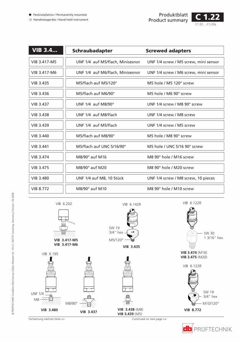
ProduktblattProduct summary
Festinstallation / Permanently mounted
Handmessgeräte / Hand-held instrument
©PR
ÜFT
ECH
NIK
Con
diti
on M
onit
orin
g | O
skar
-Mes
ster
-Str
. 19
-21
| 857
37 Is
man
ing,
Ger
man
y | V
ersi
on:
04.2
008
VIB 3.4... Schraubadapter Screwed adapters
C 1.22
VIB 3.417-M5 UNF 1/4 auf M5/flach, Minisesnor UNF 1/4 screw / M5 screw, mini sensor
VIB 3.417-M6 UNF 1/4 auf M6/flach, Minisesnor UNF 1/4 screw / M6 screw, mini sensor
VIB 3.435 M5/flach auf M5/120° M5 hole / M5 120° screw
VIB 3.436 M5/flach auf M6/90° M5 hole / M6 90° screw
VIB 3.437 UNF 1/4 auf M8/90° UNF 1/4 screw / M8 90° screw
VIB 3.438 UNF 1/4 auf M8/flach UNF 1/4 screw / M8 screw
VIB 3.439 UNF 1/4 auf M5/flach UNF 1/4 screw / M5 screw
VIB 3.440 M5/flach auf M8/90° M5 hole / M8 90° screw
VIB 3.441 M5/flach auf UNC 5/16/90° M5 hole / UNC 5/16 90° screw
VIB 3.474 M8/90° auf M16 M8 90° hole / M16 screw
VIB 3.475 M8/90° auf M20 M8 90° hole / M20 screw
VIB 3.480 UNF 1/4 auf M8, 10 Stück UNF 1/4 screw / M8 screw, 10 pieces
VIB 8.772 M8/90° auf M10 M8 90° hole / M10 screw
C1.22 ... C1.22a
Fortsetzung nächste Seite >> Continued on next page >>
VIB 3.417-M5VIB 3.417-M6
VIB 6.202
SW 193/4" hex
VIB 8.772
M10/120°
VIB 6.122R
SW 301 3/16" hex
VIB 3.474 (M16)VIB 3.475 (M20)
VIB 6.122R
VIB 3.435
VIB 6.142R
M5/120°
SW 193/4" hex
VIB 3.437
VIB 6.195
M8/90°
VIB 3.480
M8
UNF 1/4
VIB 3.438 (M8)VIB 3.439 (M5)

ProduktblattProduct summary
©PR
ÜFT
ECH
NIK
Con
diti
on M
onit
orin
g | O
skar
-Mes
ster
-Str
. 19
-21
| 857
37 Is
man
ing,
Ger
man
y | V
ersi
on:
04.2
008
C 1.22a
Montageanleitung für VIB 3.440/VIB 3.441 Mounting instructions for VIB 3.440/VIB 3.441
Select position Bore pilot hole Bore out hole 90° countersink Tap thread Mount adapterPosition wählen Vorbohren Ausbohren Ansenken 90° Gew. schneiden Montieren
depthgage
3.5 mm1/8"
6.8 mm1/4"
3m
m
1/8"
10-20NmM8
UNC5/16-18
90°
>35 mm> 1 3/8"
Tiefen-messer
>14 mm> 9/16"
C1.22 ... C1.22a
Anwendung für VIB 3.417-x und VIB 3.435- VIB 3.441Festinstallation von Industrieaufnehmern mitM5-Gewindebolzen (VIB 6.14x) bzw. UNF-In-nengewinde in vorhandene Gewinde
• M5 flach bzw. mit 120°-Konus
• M6 flach bzw. mit 90°-Konus
• M8 flach bzw. mit 90°-Konus,
• UNC 5/16 mit 90°-Konus,
Anwendung für VIB 3.474 - VIB 3.474Festinstallation von Beschleunigungsaufneh-mern zur Überwachung von Wälzlagern inTurbo-Verdichtern. Der Adapter wird anstelleeiner Verschraubung am Turbo-Verdichter ein-gesetzt.Bei der Wahl der Aufnehmer und Verkabelungist der hohe Temperaturbereich (ca. 130°C) desTurbo-Verdichters zu beachten.Gleitlager können mit diesen Adaptern nichtüberwacht werden.
Application for VIB 3.417-x and VIB 3.435 -VIB 3.441This adapters fit the flat-bottomed accelerom-eters (e.g. VIB 6.142R or VIB 6.195) into
• M5 threaded holes / flat or 120° c.sinking
• M6 threaded holes/ flat or 90° c. sinking
• M8 threaded holes / flat or 90° c.sinking
• UNC 5/16 th. holes / 90° countersinking
Application for VIB 3.474 - VIB 3.475Permanent installation of acceleration trans-ducers for monitoring the bearings in turbo-chargers.The adapter is used instead of a screw fittingon the turbocharger. The threaded length ofthe adapter is adjusted accordingly.When selecting the transducer and cabling,bear in mind the high temperature range(approx. 130°C) of the turbocharger.Slide bearings cannot be monitored usingthese adapters.
Application for VIB 8.772This adapter can be used to install the industri-al accelerometer (M8 thread) in an existingM10 hole, e.g. jack ring thread on a motor.
Anwendung für VIB 8.772Festinstallation von Industrieaufnehmern mitGewinde M8 (90°-Konus) in vorhandene Ge-winde M10, z.B. in Gewinde von Kranösen anMotoren.
VIB 3.474 /VIB 3.475

ProduktblattProduct summary
Festinstallation / Permanently mounted
Handmessgeräte / Hand-held instrument
©PR
ÜFT
ECH
NIK
Con
diti
on M
onit
orin
g | O
skar
-Mes
ster
-Str
. 19
-21
| 857
37 Is
man
ing,
Ger
man
y | V
ersi
on:
04.2
008
VIB 3.450 Tastspitze für mobilen Probe tip for hand-heldIndustrieaufnehmer, M5 flach accelerometer, M5 flat
C 1.23
19 mm / 3/4"73
mm
/ 2
3/4
"
TastspitzeProbe tip
VIB 6.142R
AnwendungMit der Tastspitze kann der Aufnehmer alsmobile Handsonde verwendet werden.
Technische DatenMaterial AluminiumGewicht 30g
ApplicationThe transducer can be used as a mobile hand-held probe through use of a contact tip.
Technical dataMaterial AluminumWeight 30g
M5

ProduktblattProduct summary
©PR
ÜFT
ECH
NIK
Con
diti
on M
onit
orin
g | O
skar
-Mes
ster
-Str
. 19
-21
| 857
37 Is
man
ing,
Ger
man
y | V
ersi
on:
04.2
008
C 1.23a
Leere Seite This page has intentionally been left blank.

ProduktblattProduct summary
Festinstallation / Permanently mounted
Handmessgeräte / Hand-held instrument
©PR
ÜFT
ECH
NIK
Con
diti
on M
onit
orin
g | O
skar
-Mes
ster
-Str
. 19
-21
| 857
37 Is
man
ing,
Ger
man
y | V
ersi
on:
04.2
008
Verlängerung für Extension post for industrialIndustrieaufnehmer, M8 x 55 mm accelerometer, M8 x 55 mmVIB 8.586
VIB 8.587 M8 x 95 mm M8 x 95 mm
VIB 8.588 M8 x 170 mm (nur Stoßimpulse) M8 x 170 mm (shock pulse only)
VIB 8.589 M8 x 35 mm M8 x 35 mm
VIB 8.590 UNC 5/16 x 2 1/8" UNC 5/16 x 2 1/8"
VIB 8.591 UNC 3/8 x 3 3/4" UNC 3/8 x 3 3/4"
VIB 8.592 UNC 1/2 x 6 5/8" (nur Stoßimpulse) UNC 1/2 x 6 5/8" (shock pulse only)
ApplicationAs its name implies, the extension post pro-vides an extra-long shaft to allow measure-ment in locations where the stem of theIndustrial Accelerometer does not fit directlyat the measurement surface. This stud is avail-able in various lengths with an M8 or UNCthread at its bottom.
NotesThe longest extension posts (170 mm and 6 5/8") should be used only for bearing conditionreadings and not for general vibration mea-surements.
Mounting instructions: see overleaf.
C 1.24
AnwendungZur Festinstallation von Industrieaufnehmernan Messstellen, die schwer zugänglich sindoder an denen der Aufnehmer nicht direktmontiert werden kann. Die Verlängerung ist-mit M8- oder UNC-Gewinde erhältlich.
HinweisDie längsten Versionen (170 mm und 6 5/8")eignen sich nur für Stoßimpulsmessungen!Schwingungsmessungen sind damit nichtmöglich (erhöhte Schwingungsamplituden).
Montageanleitung: siehe nächste Seite
Ø = 12 mm , 1/2"
Ø < 15 mm , 0.6"
C1.24 ... C1.24a

ProduktblattProduct summary
©PR
ÜFT
ECH
NIK
Con
diti
on M
onit
orin
g | O
skar
-Mes
ster
-Str
. 19
-21
| 857
37 Is
man
ing,
Ger
man
y | V
ersi
on:
04.2
008
C 1.24a
Montageanleitung für VIB 8.586-8/VIB 8.590 Mounting instructions for VIB 8.586-8/VIB 8.590
Select position Bore pilot hole Bore out hole 90° countersink Tap thread Mount extensionPosition wählen Vorbohren Ausbohren Senken 90° Gew. schneiden Montieren
depthgage
3.5 mm1/8"
6.8 mm1/4"
3m
m
1/8"
10-20Nm
M8
UNC5/16-18
90°
>35 mm> 1 3/8"
Tiefen-messer
>14 mm> 9/16"
C1.24 ... C1.24a

ProduktblattProduct summary
Festinstallation / Permanently mounted
Handmessgeräte / Hand-held instrument
©PR
ÜFT
ECH
NIK
Con
diti
on M
onit
orin
g | O
skar
-Mes
ster
-Str
. 19
-21
| 857
37 Is
man
ing,
Ger
man
y | V
ersi
on:
04.2
008
Only these tools should be used to preparemeasurement locations for industrial acceler-ometer mounting.
In addition, drill bits of sizes 3.5 mm (1/8")(with depth gage) and 6.8 mm (1/4") arerequired.
Use a torque wrench to tighten the acceler-ometer into place with 10-20 Nm of torque.
VIB 8.693 Gewindebohrer M8 M8 thread tap
VIB 8.696 Gewindebohrer UNC 5/16" UNC 5/16" thread tap
VIB 8.694 90°-Senker 90° countersink bit
Das Vorbereiten der Montagelöcher sollteausschließlich mit diesem Bohrwerkzeug er-folgen.
Zum Vor- und Aufbohren der Montagelöcherbenötigt man außerdem einen Bohrer 3,5 mitTiefenlehre und einen Bohrer 6,8.
Zur Endmontage der Aufnehmer ist ein Dreh-momentschlüssel zu verwenden.
VIB 8.693M8
VIB 8.696UNC 5/16"
VIB 8.694
C 1.25
>35 mm> 1 3/8"
Montageanleitung Mounting instructions
Select position Bore pilot hole Bore out hole 90° countersink Tap thread Mount sensorPosition wählen Vorbohren Aufbohren 90° Ansenken Gew. schneiden Montieren
>14 mm> 9/16"
depthgage3.5 mm
1/8"6.8 mm1/4" 3
mm
1/
8" 10-20NmM8
UNC5/16-18
90°
Montagewerkzeugfür Industrieaufnehmer
Tools required formounting industrial accelerometers

ProduktblattProduct summary
©PR
ÜFT
ECH
NIK
Con
diti
on M
onit
orin
g | O
skar
-Mes
ster
-Str
. 19
-21
| 857
37 Is
man
ing,
Ger
man
y | V
ersi
on:
04.2
008
C 1.25a
Leere Seite This page has intentionally been left blank.

ProduktblattProduct summary
Festinstallation / Permanently mounted
Handmessgeräte / Hand-held instrument
©PR
ÜFT
ECH
NIK
Con
diti
on M
onit
orin
g | O
skar
-Mes
ster
-Str
. 19
-21
| 857
37 Is
man
ing,
Ger
man
y | V
ersi
on:
04.2
008
VIB 8.610 Spezialsenker Countersink bit
The measurement location may not alwaysprovide the ideal surface for conducting vibra-tion or bearing measurements to the VI-BROTIP probe - especially if the best availablemeasurement location has a curved surface.This is why the PRÜFTECHNIK countersink bitVIB 8.610 should always be used to preparethe location for measurement. The counter-sink produces a hole smaller than VIBROTIP'sVIBSCANNER's or TIPTECTOR's vibration andshock pulse sensor. A ring-shaped contact areais thereby created between the sensor and themeasurement surface, providing optimal sig-nal transmission. And as an important sidebenefit for reliable comparison between suc-cessive readings: this clearly marks the mea-surement location so that readings are alwaystaken in the exact same spot.
The bit has a hexagonal shaft compatible witha standard battery-operated screwdriver. Thisis recommended in preference to an electricdrill as only a relatively shallow countersunkhole is needed.
Nicht alle Messstellen sind zur Schwingungs-oder Stoßimpulsmessung geeignet. Um eineideale Messstelle, vor allem auf gewölbtenOberflächen, zu erhalten, bietet die PRÜF-TECHNIK AG den Spezialsenker VIB 8.610 an.Mit diesem Spezialsenker und einem Ak-kuschrauber mit Bit-Futter wird eine Öffnunggefräst, die kleiner als der Schwingungs- undStoßimpulsaufnehmer des VIBROTIP, VIB-SCANNER bzw. TIPTECTOR ist. Die so entste-hende ringförmige Kontaktfläche zwischenSensor und Meßoberfläche garantiert besteSignalübertragung.
Gehen Sie wie folgt vor:
1. Messstelle säubern und markieren.
2. Messstelle mit Akku-Schrauber soweit auf-bohren, bis die ringförmige Fläche des Sen-kers auf der Meßoberfläche aufliegt (s.o.).
3. Metallspäne und Reste mit Preßluft aus derBohrung ausblasen.
Achten Sie darauf, daß keine Späne in derBohrung verbleiben. Setzen Sie den VI-BROTIP-Aufnehmer möglichst senkrecht zurOberfläche auf. Andernfalls entspricht dieMeßrichtung nicht den ISO-Normen!
ENT
6,3 mm
C 1.26

ProduktblattProduct summary
©PR
ÜFT
ECH
NIK
Con
diti
on M
onit
orin
g | O
skar
-Mes
ster
-Str
. 19
-21
| 857
37 Is
man
ing,
Ger
man
y | V
ersi
on:
04.2
008
Leere Seite This page has intentionally been left blank.
C 1.26a

ProduktblattProduct summary
Festinstallation / Permanently mounted
Handmessgeräte / Hand-held instrument
©PR
ÜFT
ECH
NIK
Con
diti
on M
onit
orin
g | O
skar
-Mes
ster
-Str
. 19
-21
| 857
37 Is
man
ing,
Ger
man
y | V
ersi
on:
04.2
008
ApplicationThe bonding kit provides quick and economi-cal mounting of bonded VIBCODE measure-ment studs (VIB 8.685), VIB 6.10x accelerome-ter or the VIB 3.43x bonded adapter onto thecast metal surface of bearing housings.
AnwendungMontage der Industrieaufnehmer VIB 6.10x,der VIBCODE-Klebebolzen VIB 8.685 und derKlebeadapter VIB 3.43x auf Metalloberflächenvon Lagergehäusen oder Maschinenteilen.
VIB 8.477 Klebehilfe Bonding aid
VIB 8.685VIB 3.100 Klebeset, Bonding kit,2x 100g 2x 100g (2x 3 1/2 oz.)
VIB 8.477
VIB 3.100
Bonding instructions
> 5 mm> 1/4"
(option)
>35 mm> 1 3/8"
Allow clearance Mounting surface: (Option: bore hole Apply compound Press & turn studfor transducer flat & roughened for centering pin) to both surfaces into surface
Klebeanleitung
Platz lassen Montagefläche (Option: Loch für Klebstoff auftragen Bolzen andrückenabflachen & aufrauhen Fixierstift bohren) (Bolzen & Maschine) & eindrehen
>20 mm>3/4"
3.6 mm1/8"
C 1.27

ProduktblattProduct summary
©PR
ÜFT
ECH
NIK
Con
diti
on M
onit
orin
g | O
skar
-Mes
ster
-Str
. 19
-21
| 857
37 Is
man
ing,
Ger
man
y | V
ersi
on:
04.2
008
Leere Seite This page has intentionally been left blank.
C 1.27a

ProduktblattProduct summary
Festinstallation / Permanently mounted
Handmessgeräte / Hand-held instrument
©PR
ÜFT
ECH
NIK
Con
diti
on M
onit
orin
g | O
skar
-Mes
ster
-Str
. 19
-21
| 857
37 Is
man
ing,
Ger
man
y | V
ersi
on:
04.2
008
VIB 8.685VIB 8.749 Adapter für Stromvorverstärker Current Linedrive converter
BeschreibungDieser Adapter wandelt das Signal einesSchwingungssensors mit Strom-Linedrive-Vor-verstärker in ein Spannungssignal um. DerAdapter wird von zwei Batterien (9-Volt-Block) versorgt.
HinweisÜber einen Tastschalter kann der Batteriela-dezustand angezeigt werden. Die Batteriensind leer, wenn bei Tastendruck die grüne LEDnicht leuchtet.
Technische SpezifikationEmpfindlichkeit 1 mV / 1µA
Genauigkeit ±1% vom Meßwert
Dichtigkeit IP 50
Temperaturbereich 10°C bis 40°C
Versorgung 2 x 9 Volt Block
Stromverbrauch 6 mA (mit Aufnehmer)
Laufzeit ca. 75h mit AlMn Batterien
Abmessungen 35 x 110 x 70 mm (HxBxT)
Gewicht 320g inkl. Batterien
DescriptionThis adapter converts the current signal of aline drive sensor into a voltage signal. Theadapter is powered by two 9-volt batteries.
NoteBattery condition can be checked at the pressof a button: if the green LED fails to illumina-te, the batteries are depleted.
Technical specificationSensitivity 1 mV / 1 µA
Accuracy To within 1% of measured value
Protection IP 50
Temperature range 10° C to 40° C / 50° F to 104° F
Power supply 2 x 9 volt batteries
Current consumption 6 mA (w/ sensor)
Operating duration approx. 75h for AlMn batteries
Dimensions 35 x 110 x 70 mm(H x W x D) 1 1/3" x 4 1/3" x 6 2/3"
Weight 320g / 11.3 oz. (w/ batteries)
Batt. Test
OUT (TNC): 1 mV/m/s²5,35 mV/m/s²
IN (QLA): 1 µA/m/s²5,35 µA/m/s²
C 1.28

ProduktblattProduct summary
©PR
ÜFT
ECH
NIK
Con
diti
on M
onit
orin
g | O
skar
-Mes
ster
-Str
. 19
-21
| 857
37 Is
man
ing,
Ger
man
y | V
ersi
on:
04.2
008
C 1.28a
Leere Seite This page has intentionally been left blank.

ProduktblattProduct summary
Festinstallation / Permanently mounted
Handmessgeräte / Hand-held instrument
©PR
ÜFT
ECH
NIK
Con
diti
on M
onit
orin
g | O
skar
-Mes
ster
-Str
. 19
-21
| 857
37 Is
man
ing,
Ger
man
y | V
ersi
on:
04.2
008
C 1.29C1.29 ... C1.29a
VIB 8.685VIB 5.710 Produkt abgekündigt Product expired

ProduktblattProduct summary
©PR
ÜFT
ECH
NIK
Con
diti
on M
onit
orin
g | O
skar
-Mes
ster
-Str
. 19
-21
| 857
37 Is
man
ing,
Ger
man
y | V
ersi
on:
04.2
008
C 1.29aC1.29 ... C1.29a

ProduktblattProduct summary
Festinstallation / Permanently mounted
Handmessgeräte / Hand-held instrument
©PR
ÜFT
ECH
NIK
Con
diti
on M
onit
orin
g | O
skar
-Mes
ster
-Str
. 19
-21
| 857
37 Is
man
ing,
Ger
man
y | V
ersi
on:
04.2
008
Adapter for machine protection systemsVIB 8.747
Application and descriptionWith the aid of the adapter VIB 8.747, theVIBROCORD or VIBSCANNER can measure asignal on a Bently Nevada machine protectionsystem (e.g. series 3300). The adapter has twochannels for tapping the signal. A third out-put channel converts a sinus signal into a 5Vsssquare wave signal (Trigger).If the signal is too large for the measuringdevice, a switch for each of the two signalchannels on the main board can be used toattenuate the input signal by a factor of 3 or 6.The input and output signal lines for eachchannel are connected via TNC connectors.Also, a binder connector at the trigger outputhas the same pin assignment as thePRÜFTECHNIK trigger sensors.The voltage supply consists of two 9V blockbatteries. To switch on the device, there is arotary switch located on the narrow side.When switched on, a green LED illuminates.This shows that both batteries still have avoltage charge greater than 6V.
NoteBefore the initial commissioning, the protec-tive caps on the battery poles must be re-moved.
Anwendung und BeschreibungMit Hilfe dieses Adapters kann VIBSCANNERoder VIBROCORD Signale an einem BentlyNevada-Maschinenschutzsystem (z.B. Serie3300) messen. Der Adapter verfügt für denSignalabgriff über zwei Kanäle. Ein dritterAusgangskanal wandelt ein Sinussignal in ein5Vss-Rechtecksignal um (Trigger).Falls das Signal für die Messgeräte zu großsein sollte, kann man es um den Faktor 3 oder6 abschwächen.Der Anschluß für die Ein- und Ausgangskanäleerfolgt über TNC-Buchsen. Der Trigger-Aus-gang (BINDER-Buchse) hat die gleiche Pin-Belegung wie die Trigger-Sensoren der PRÜF-TECHNIK AG.Der Adapter wird mit zwei 9V-Blockbatterienversorgt und über einen Drehschalter einge-schaltet. Beim Einschalten leuchtet eine grüneLED auf, wenn beide Batterien noch eineSpannung von größer 6V haben.
Hinweis:Vor der Erst-Inbetriebnahme sind die Schutz-kappen von den Batteriepolen zu entfernen.
Adapter fürMaschinenschutzsysteme
Signal IN(BNC)
ON / OFF
Trigger IN(BNC)
Signal OUT(TNC)
Trigger OUT (TNC/Binder)
Signal OUT(TNC)
Trigger OUT (TNC/Binder)
52 mm2.05 inch
163 mm6.42 inch
C 1.30C1.30 ... C1.30a

ProduktblattProduct summary
©PR
ÜFT
ECH
NIK
Con
diti
on M
onit
orin
g | O
skar
-Mes
ster
-Str
. 19
-21
| 857
37 Is
man
ing,
Ger
man
y | V
ersi
on:
04.2
008
Technical data - VIB 8.747
Power supply 2 pieces 9V block batteries 6LR61
Inputs Impedance > 1MOhm
Outputs Signal outputs Impedance = 100 Ohm
Signal attenuation 1:3 or 1:6Frequency range 0 to 16kHz
Trigger output 5Vss
square-wave signal
Dimensions 19 x 8 x 6 cm (LxWxH)71/2 x 3 x 21/3 inch
Weigth approx. 800 g13/4 lb.
Technische Daten - VIB 8.747
Versorgung Zwei 9V Blockbatterien (6LR61)
Eingänge Impedanz > 1MOhm
Ausgänge Signal Impedanz = 100 Ohm
Signalabschwächung 1:3 oder 1:6Frequenzbereich 0 bis 16kHz
Trigger 5Vss
Rechtecksignal
Abmessungen 19 x 8 x 6 cm (LxBxH)
Gewicht ca. 800 g
B A
Applikation / Application
VIBSCANNER
VIB 8.747
3x BNC - BNC(VIB 344221-L)
VIB 5.446(automaticswitch box)
2 x VIB 5.433VIB 5.432-2,9(Trigger cable)
2 x VIB 93055
C 1.30aC1.30 ... C1.30a
Bently Messverstärker /Bently measurement amplifier
3x BNC - BNC
VIB 5.631-5(Trigger cable)
2 x VIB 4.704-5(Sensor cable)
TNC
BNC
VIB 8.747
B A
VIB 5.445(manualswitch box)
VIB 5.433
2 x TNC - TNC(VIB 311221-L)
VIB 93055
VIBROCORD

ProduktblattProduct summary
Festinstallation / Permanently mounted
Handmessgeräte / Hand-held instrument
©PR
ÜFT
ECH
NIK
Con
diti
on M
onit
orin
g | O
skar
-Mes
ster
-Str
. 19
-21
| 857
37 Is
man
ing,
Ger
man
y | V
ersi
on:
04.2
008
C 1.31
The VIB 8.745 installation checker lets youensure that remotely mounted vibration sen-sors are properly connected. The unit featuresthree LED's which light up according to thestatus of the connection:
Green LED = Installation is correctRed LED = Short circuitYellow LED = Ground loop
Additionally, battery test terminals allow bat-tery voltage checking: if voltage is less than5V, the yellow LED lights up. If the batteryvoltage is sufficient, yet none of the LED'slights up, then the connection to the sensorhas been broken.
The installation checker may also be used asshown above to test VIBRONET or VIBREXsensor connections for continuous monitoringof machine condition parameters.
Attach the leads from the sensor to bechecked via the QLA jacks on the top of theinstallation checker, if necessary using theVIB 4.705 QLA-BNC plug adapter.
Alternatively, the sensor leads may be con-nected to the jacks on the top of the unit viaBNC or TNC adapter (not included), as shownabove, or using ordinary banana plugs.
QLA jackQLA-Buchse
VIB 8.745 Installationsprüfer Installation checker
Battery testBatterietest
Sensor testSensortest
S2 S4 S6 S8
S1 S3 S5 S7 S9
VIB
BU
S -
MU
X 3
49
4 NE
XT
M
UX
MA
ST
ER
LIN
EMit dem Installationsprüfer VIB 8.745 läßt sichfeststellen, ob die Schwingungsaufnehmerkorrekt angeschlossen sind. Folgende Zustän-de werden über drei LEDs angezeigt:
grüne LED = Anschluß korrektrote LED = Kurzschlußgelbe LED = Erdschluß
Zusätzlich kann die Batteriespannung über-prüft werden: Bei einer Spannung von weni-ger als 5 V leuchtet die gelbe LED auf. Ist dieBatteriespannung ausreichend und leuchtetkeine der LED auf, so ist die Verbindung zumSensor unterbrochen.
Gehen Sie zum Prüfen wie folgt vor:Schließen Sie den zu überprüfenden Aufneh-mer an die QLA-Buchsen auf dem Gerät an.Alternativ kann der Aufnehmer über ein Stan-dard-BNC oder TNC-Adapter oder mit Bana-nenstecker oben am Gerät angeschlossen wer-den (nicht im Lieferumfang enthalten) .

ProduktblattProduct summary
©PR
ÜFT
ECH
NIK
Con
diti
on M
onit
orin
g | O
skar
-Mes
ster
-Str
. 19
-21
| 857
37 Is
man
ing,
Ger
man
y | V
ersi
on:
04.2
008
C 1.31a
Leere Seite This page has intentionally been left blank.

ProduktblattProduct summary
Festinstallation / Permanently mounted
Handmessgeräte / Hand-held instrument
©PR
ÜFT
ECH
NIK
Con
diti
on M
onit
orin
g | O
skar
-Mes
ster
-Str
. 19
-21
| 857
37 Is
man
ing,
Ger
man
y | V
ersi
on:
04.2
008
BATT
ON/OFF
10m/s10mm/s10um
2R
The vibration calibrator VIB 8.560 is a handytest device for checking accelerometer calibra-tion. The unit contains a mechanical oscillatorwhich can be used to test the entire signalpath from the sensor through the cable to theelectronics and data processing. The sensorcan be screwed onto the calibrator (M5 or M8thread) or mounted using the VIB 8.736 mag-net to measure any parameter required, e.g.acceleration, velocity, displacement, RMS,peak-to-peak etc. (See overleaf for adapters.)
This unit is powerful enough to accuratelymeasure objects of weight up to 300g (10.7oz.), which is significantly higher than otheravailable calibrators. This model is thereforeideally suited to measuring most accelerome-ter types, including VIBROTIP and the industri-al accelerometer using the adapters shown onthe following page.
An internal rechargeable battery runs thecalibrator for at least 2 hours, and a two-colorLED clearly shows battery status. A mainsadapter is supplied with the unit to allow bothmains operation and simultaneous quick bat-tery charging.
VIB 8.560 Schwingungskalibrator Vibration calibrator
Der Schwingungskalibrator VIB 8.560 ist einhandliches, transportables Prüfgerät zur Kali-brierung der Tandem-Piezo-Beschleunigungs-aufnehmer.
Durch das mechanische Prüfsignal des Oszilla-tors kann die gesamte Meßkette einschließlichder Meßkabel vollständig geprüft werden.Die Aufnehmer können verschraubt (M 5 oderM 8) oder mit der Magnethalterung VIB 8.736am Oszillator befestigt werden (Adapter: sie-he Rückseite). Das Signal kann als Schwingbe-schleunigung, -geschwindigkeit oder -weg je-weils als RMS- oder Spitze-Spitze-Wert gemes-sen werden.
Da mit diesem Gerät Aufnehmer mit einemGewicht von bis zu 300 g vermessen werdenkönnen, eignet es sich besonders zum Kali-brieren des VIBROTIP® und anderer Aufneh-mer mit größeren Massen. Diese werden überdie umseitig abgebildeten Adapter an denKalibrator angeschlossen.
Der interne Akku ermöglicht einen netz-unabhängigen Betrieb über zwei Stunden.Die zweifarbige Leuchtdiode zeigt den Akku-Ladezustand an. Mit dem mitgelieferten Netz-teil ist ein batteriegepufferter Netzbetriebund ein schnelles Aufladen des Akkus mög-lich.
VIB 8.741 Adapter für VIBROTIP/ VIBSCANNER Adapter for VIBROTIP/ VIBSCANNER
VIB 8.742 Adapter für Industrieaufnehmer (M8) Adapter for accelerometers (M8)
C 1.32C1.32 ... C1.32a

ProduktblattProduct summary
©PR
ÜFT
ECH
NIK
Con
diti
on M
onit
orin
g | O
skar
-Mes
ster
-Str
. 19
-21
| 857
37 Is
man
ing,
Ger
man
y | V
ersi
on:
04.2
008
Adapters for VIBROTIP/ VIBSCANNER, in-dustrial accelerometer
These adapters are screwed onto the calibra-tor. In connection with a VIBCODE stud (VIB8.680/ VIB 8.679) the VIB 8.742 adapter can beused to attach a VIBCODE transducer to thecalibrator.The example above shows the VIB 8.741 adapt-er in use.
Technical DataMax. weight of object to be measured (incl. VIB 8.742) 300gAcceleration 10 m/s² ±3%Velocity 10 mm/s ±3%Displacement 10 µm ±3%Frequency 159.15 Hz ±0.02%Rotation frequency 1000/s ±0.02%Level control optical and acousticSwitch off time (automatic) after 10 minutes
VIB 8.742
BATT
ON/OFF
10m/s10mm/s10um
2
ENTENT
M
VIB 8.741
Adapter für VIBROTIP/ VIBSCANNER undIndustrieaufnehmer
Diese Adapter werden auf den Kalibrator ge-schraubt. Zusammen mit dem VIBCODE Mess-punkt M8 (VIB 8.680/ VIB 8.679) kann derAdapter VIB 8.742 auch zum Anschluß desVIBCODE Aufnehmers verwendet werden.Das Beispiel oben zeigt die Anwendung desAdapters VIB 8.741.
Technische DatenMaximale Masse des Meßobjektes (inkl. VB 8.742) 300 gBeschleunigung 10 m/s² ±3%Geschwindigkeit 10 mm/s ±3%Auslenkung 10 µm ±3%Schwingfrequenz 159.15 Hz ±0.02%Kreisfrequenz 1000/s ±0.02%Pegelkontrolle optisch und akustischAbschaltzeit (Automatik) nach 10 Minuten
C 1.32aC1.32 ... C1.32a

ProduktblattProduct summary
Festinstallation / Permanently mounted
Handmessgeräte / Hand-held instrument
©PR
ÜFT
ECH
NIK
Con
diti
on M
onit
orin
g | O
skar
-Mes
ster
-Str
. 19
-21
| 857
37 Is
man
ing,
Ger
man
y | V
ersi
on:
04.2
008
VIB 8.607-1.5 Magnet- MagneticTemperaturfühler temperature probe
In order to reach poorly-accessible tempera-ture measurement locations, PRÜFTECHNIKoffers the magnetic temperature probe.. Apowerful magnet makes for extremely quickand simple mounting.
The magnetic temperature probe lets youmeasure temperatures up to 240° C / 464° F.
To connect this probe to the VIBROTIP orVIBSCANNER data collector, remove the built-in temperature probe as described in theoperating instructions.
Technical dataMeas. range -50°C ... +240°C / -58°F ... +464°F
Sensitivity 0,040 mV/°C
Accuracy < 3°C / 4°F
Probe diameter 14 mm / 0.55"
Cable length 1,5 m / 5ft.
Connector QLA
Weight 28 g / 1 oz.
Dieser Magnet-Temperaturfühler eignet sichbesonders für schwer zugängliche Tempera-turmessstellen. Der starke Magnet sorgt füreine einfache und sichere Montage am Ma-schinengehäuse.
Mit dem Magnet-Temperaturfühler könnenTemperaturen bis 240°C gemessen werde.
Um die Handsonde am VIBROTIP bzw. VIB-SCANNER Datensammler anschließen zu kön-nen, muß erst deren integrierter Temperatur-fühler abgesteckt werden.
Technische DatenMessbereich -50°C ... +240°C
Empfindlichkeit 0,040 mV/°C
Genauigkeit < 3°C
Durchmesser 14 mm
Kabellänge 1,5 m
Anschluß QLA
Gewicht 28 g
C 1.33

ProduktblattProduct summary
©PR
ÜFT
ECH
NIK
Con
diti
on M
onit
orin
g | O
skar
-Mes
ster
-Str
. 19
-21
| 857
37 Is
man
ing,
Ger
man
y | V
ersi
on:
04.2
008
C 1.33a
leere Seite Empty page

ProduktblattProduct summary
Festinstallation / Permanently mounted
Handmessgeräte / Hand-held instrument
©PR
ÜFT
ECH
NIK
Con
diti
on M
onit
orin
g | O
skar
-Mes
ster
-Str
. 19
-21
| 857
37 Is
man
ing,
Ger
man
y | V
ersi
on:
04.2
008
VIB 8.608 Temperatur-Handsonde Hand-held temperature probe
As an alternative to VIBROTIP's or VIBSCAN-NER's built-in temperature probe, a hand-heldprobe is also available. This probe measures upto 500°C / 932°F.
To connect this probe, remove the built-intemperature probe as described in the operat-ing instructions. Then insert into the samesocket the plug of the hand-held temperatureprobe.
Technical dataMeas. range -50°C ... +500°C / -58°F ... +932°F
Sensitivity 0.040 mV/°C
Accuracy < 3°C / 4°F
Dimensions, LxØ 250 mm x 18 mm/ 9.8" x 0.7"
Probe tip, Ø 3 mm / 0.1"
Connector QLA
Weight 83 g / 2.9 oz.
Diese Handsonde wird zur Messung von Tem-peraturen bis 500°C eingesetzt. Mit der lan-gen, schmalen Messspitze können auchschwer zugängliche Messstellen erreicht wer-den.
Um die Handsonde am VIBROTIP bzw. VIB-SCANNER Datensammler anschließen zu kön-nen, muß erst deren integrierter Temperatur-fühler abgesteckt werden.
Technische DatenMessbereich -50°C ... +500°C
Empfindlichkeit 0,040 mV/°C
Genauigkeit < 3°C
Abmessungen, LxØ 250 mm x 18 mm
Fühlerspitze, Ø 3 mm
Anschluß QLA
Gewicht 83 g
C 1.34

ProduktblattProduct summary
©PR
ÜFT
ECH
NIK
Con
diti
on M
onit
orin
g | O
skar
-Mes
ster
-Str
. 19
-21
| 857
37 Is
man
ing,
Ger
man
y | V
ersi
on:
04.2
008
C 1.34a
leere Seite Empty page

ProduktblattProduct summary
Festinstallation / Permanently mounted
Handmessgeräte / Hand-held instrument
©PR
ÜFT
ECH
NIK
Con
diti
on M
onit
orin
g | O
skar
-Mes
ster
-Str
. 19
-21
| 857
37 Is
man
ing,
Ger
man
y | V
ersi
on:
04.2
008
VIB 6.610 Einbau-Temperaturfühler Temperature probe PT 100PT 100 mit Klemmstück for permanent mounting
Dieser Fühler mißt die Temperatur mit einemPt-100-Widerstand und wird zur Temperatur-überwachung mit einem Online-System ein-gesetzt.
Die Montage an der Maschine erfolgt miteiner druckdichten Durchgangsverschrau-bung.
Technische DatenTyp Widerstandsthermometer Pt 100
Messbereich 0 ... +200 °C
Schutzrohr rost- und säurebeständiger Stahl
Grenzabweichung DIN IEC 751 Kl. B
Anschluß Koaxialkabel, 5 m
Schutzart, Anschluß IP54
Abmessungen siehe nächste Seite
Ex-Schutz (Option):Der Temperatursensor PT 100 Typ RL-70-40 EX (Fa. RösselMeßtechnik GmbH) ist vergossen und nach Herstellerklä-rung 500 V gegen Masse geprüft. Seine Eigenerwärmungbei 18mA ist 32mW (vernachlässigbar).
The temperature of machine components canbe measured using a Pt100 resistance ther-mometer mounted through the machinehousing with a pressure-proof threaded fit-ting.
Technical dataType Pt 100 resistance thermometer
Measurement range 0°C to 200°C / 32°F to 424°F
Protective sheath Rust- and acid-resistant steel
Limit deviation DIN IEC 751 Class B
Connection Coaxial cable, 5 m / 16 ft.
Protection, connector IP54
Dimensions see next page
Intrinsic safety (option)Temperature sensor of the Rössel Meßtechnik GmbH com-pany is cast in plastic and tested with 500V against earthin compliance with the manufacturer declaration. Its selfheating of 32mW at 18mA is negligible.
C 1.35
Option
TemperaturfühlerTemperature probe
FeststellschraubeLock nut
DruckstückThrust member
MontageschraubeMounting bolt
C1.35 ... C1.35a

ProduktblattProduct summary
©PR
ÜFT
ECH
NIK
Con
diti
on M
onit
orin
g | O
skar
-Mes
ster
-Str
. 19
-21
| 857
37 Is
man
ing,
Ger
man
y | V
ersi
on:
04.2
008
C 1.35a
Abmessungen / Dimensions - VIB 6.610
70 mm2 3/4"
48 mm1 15/16"
4 mm3/16"
SW 14
M 810 mm3/8"
C1.35 ... C1.35a

ProduktblattProduct summary
Festinstallation / Permanently mounted
Handmessgeräte / Hand-held instrument
©PR
ÜFT
ECH
NIK
Con
diti
on M
onit
orin
g | O
skar
-Mes
ster
-Str
. 19
-21
| 857
37 Is
man
ing,
Ger
man
y | V
ersi
on:
04.2
008
C 1.36C1.36 ... C1.36a
Drehzahlsensor (induktiv) RPM sensor (inductive)M18 x 76.5 M18 x 76.5VIB 5.992 BA
D > 10 mm
Messmarke
max. 8 mm
LED
Alle Maße in mm
24
M18x1
LED
76,5
50,5
10
AnwendungDer Sensor wird in den Online-Überwachungs-systemen als Triggergeber und zur Messungder Maschinendrehzahl eingesetzt.
HinweisUm eine optimale Signalerfassung zu gewähr-leisten, ist der Sensor nahe an einer geeigne-ten Messmarken zu montieren (z.B. Kupp-lungsschrauben).
Technische Daten: VIB 5.992-BATyp DC / 3-Draht / PNP / ÖffnerEinbau nicht bündigMessprinzip InduktivSchaltabstand 8 mmWiederholgenauigkeit < 5%Anzeige Schaltelement ein Ja
Betriebsspannung 10 ... 30 VLaststrom 200 mASchaltfrequenz 600 HzLeerlaufstrom < 4/12 mASpannungsfall < 1,5 VReststrom 0,5 mAKurzschlussschutz jaVerpolschutz ja
Umgebungstemperatur -25°C bis +70°CGehäusematerial Messing vernickeltWerkstoff aktive Fläche: PA 12Schutzart IP 68Abmessung M18 x 1 x 76,5 mm (DxH)Anschlußart Kabel (LiYY-O), 12m lang
ApplicationThe inductive RPM sensor VIB 5.992-BA is usedin online condition monitoring systems as atrigger sensor and for the measurement ofmachine RPM.
NoteThe sensor should be mounted close to asuitable gage mark (e.g. coupling screws) toensure optimum signal acquisition.
Technical data: VIB 5.992-BASensor type DC / 3-lead/ PNP / openerInstallation Not flushMeas. principle inductiveSwitching distance 8 mmRepeat accuracy < 5%Switching status display Yes
Operating voltage 10 ... 30 VLoad current 200 mASwitching frequency 600 HzNo-load current < 4/12 mAVoltage drop < 1,5 VCutoff current 0,5 mAShort-circuit protection yesReverse-connect protection yes
Ambient temperature -25°C to +70°CHousing material: Brass, nickel-platedActive material surface: PA 12Protection class: IP 68Dimensions M18 x 1 x 76,5 mm (DxH)Connection cable Cable (LiYY-O), 12m / 39,4 ft

ProduktblattProduct summary
©PR
ÜFT
ECH
NIK
Con
diti
on M
onit
orin
g | O
skar
-Mes
ster
-Str
. 19
-21
| 857
37 Is
man
ing,
Ger
man
y | V
ersi
on:
04.2
008
C 1.36aC1.36 ... C1.36a
Anschluß-Schaltbild: VIB 5.992-BA Connection diagram: VIB 5.992-BA

ProduktblattProduct summary
Festinstallation / Permanently mounted
Handmessgeräte / Hand-held instrument
©PR
ÜFT
ECH
NIK
Con
diti
on M
onit
orin
g | O
skar
-Mes
ster
-Str
. 19
-21
| 857
37 Is
man
ing,
Ger
man
y | V
ersi
on:
04.2
008
C 1.37
FunctionRPM measurement is made according to theinductive proximity principle as shown above.As a magnet moves through the sensor'sinductive field, the electric current changes.The RPM value can be determined from thefrequency with which this current fluctuationoccurs.
ApplicationMachine RPM is important information: it isused for configuring nonlinear alarm curveswhich are dependent on more than one vari-able, for example, when machine vibration isRPM-dependent. Moreover, the RPM is re-quired to calculate the dBi value for shock-pulse measurement of variable-speed ma-chines.
ConnectionThe sensor is connected to the MUX with theRPM connector module VIB 8.313.
NoteThe LED on the sensor goes out each time thesensor is triggered.
FunktionDie ferromagnetisches Messmarke am Rotorinduziert bei Rotation Feldänderung im Sen-sor; die Drehzahl ergibt sich aus der Frequenzder Feldänderung.
AnwendungDrehzahlmessung im VIBRONET Online-Über-wachungssystem zur- Normierung drehzahlabhänger Signalpegel- Einstellung nichtlinearer Alarmkurven in
der VIBRONET Trend Software- Berechnung des Initialwertes (dBi) bei der
Wälzlagerüberwachung an drehzahlgere-gelten Maschinen.
AnschlußDrehzahlmodul (VIB 8.313) im VIBRONET-Mul-tiplexer
HinweisDie LED am Sensor geht aus, wenn die Mess-marke den Sensor passiert.
Option
C1.37 ... C1.37a
VIB 6.620 SET
VIB 6.620 Drehzahlsensor (induktiv) RPM sensor (inductive)
VIB 6.621 Stecker für Drehzahlsensor (induktiv) Plug for RPM sensor (inductive)
VIB 6.621
VIB 6.620
* Kabel ( RG58) nicht enthalten!* Cable ( RG58) is not included!
VIB 6.620 SET
RG58*
LED
Drehzahlsensor (induktiv) RPM sensor (inductive)mit Stecker with plug
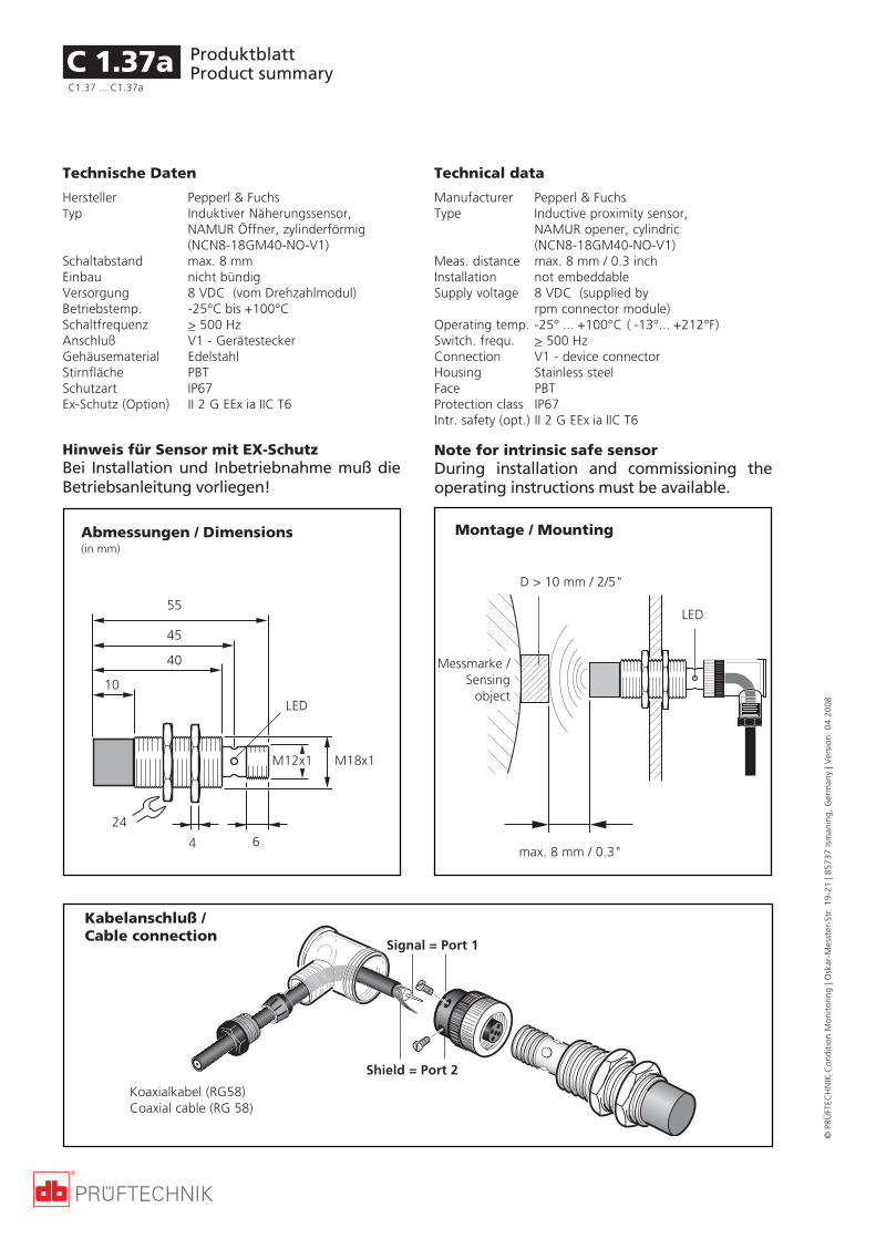
ProduktblattProduct summary
©PR
ÜFT
ECH
NIK
Con
diti
on M
onit
orin
g | O
skar
-Mes
ster
-Str
. 19
-21
| 857
37 Is
man
ing,
Ger
man
y | V
ersi
on:
04.2
008
Technische Daten
Hersteller Pepperl & FuchsTyp Induktiver Näherungssensor,
NAMUR Öffner, zylinderförmig(NCN8-18GM40-NO-V1)
Schaltabstand max. 8 mmEinbau nicht bündigVersorgung 8 VDC (vom Drehzahlmodul)Betriebstemp. -25°C bis +100°CSchaltfrequenz > 500 HzAnschluß V1 - GerätesteckerGehäusematerial EdelstahlStirnfläche PBTSchutzart IP67Ex-Schutz (Option) II 2 G EEx ia IIC T6
C 1.37a
Technical data
Manufacturer Pepperl & FuchsType Inductive proximity sensor,
NAMUR opener, cylindric(NCN8-18GM40-NO-V1)
Meas. distance max. 8 mm / 0.3 inchInstallation not embeddableSupply voltage 8 VDC (supplied by
rpm connector module)Operating temp. -25° ... +100°C ( -13°... +212°F)Switch. frequ. > 500 HzConnection V1 - device connectorHousing Stainless steelFace PBTProtection class IP67Intr. safety (opt.) II 2 G EEx ia IIC T6
C1.37 ... C1.37a
D > 10 mm / 2/5"
55
45
40
10
24
4 6
M18x1M12x1
LED
Montage / Mounting
Kabelanschluß /Cable connection
Messmarke /Sensing
object
Koaxialkabel (RG58)Coaxial cable (RG 58)
Signal = Port 1
Shield = Port 2
Hinweis für Sensor mit EX-SchutzBei Installation und Inbetriebnahme muß dieBetriebsanleitung vorliegen!
Abmessungen / Dimensions(in mm)
Note for intrinsic safe sensorDuring installation and commissioning theoperating instructions must be available.
max. 8 mm / 0.3"
LED

ProduktblattProduct summary
Festinstallation / Permanently mounted
Handmessgeräte / Hand-held instrument
©PR
ÜFT
ECH
NIK
Con
diti
on M
onit
orin
g | O
skar
-Mes
ster
-Str
. 19
-21
| 857
37 Is
man
ing,
Ger
man
y | V
ersi
on:
04.2
008
Opt. Triggersensor, aktiv Opt. trigger sensor, active
These trigger sensor emits an electric pulsewhenever a reflective tape (VIB 3.306) on therotor passes by and reflects the infrared light(IR) from the IR-LED. VIBXPERT, VIBROCORD,VIBSCANNER or VIBROSPECT then uses theresulting sequence of pulses to calculate RPM.The red LED is used to aim at the reflectivetape on the rotor.
The sensor could be mounted (most easilywith the VIB 4.330 trigger bracket) such thatthe mark passes perpendicularly to the arrowmarking on the trigger housing.
For best results, the distance between thesensor and the rotor mark should be 2 cm to50 cm / 1" to 20".
VIB 6.630
Der Triggersensor arbeitet mit Infrarot-(IR)Licht. Jedesmal wenn die Reflexmarke (VIB3.306) auf der Welle die Triggeroptik passiertund diese den Lichtreflex der IR-LED erfasst,gibt der Sensor einen elektrischen Impuls ab.Aus der Wiederholrate dieser Spannungspulseberechnet das Messgerät (VIBXPERT / VIBRO-CORD / VIBSCANNER / VIBROSPECT FFT) dieWellendrehzahl. Mit der roten LED läßt sichdie Reflexmarke auf der Welle anvisieren.
Der Triggersensor kann mit dem Trigger-Stativ(VIB 4.330) an der Welle montiert werden. DieReflexmarke und die Triggeroptik müssen par-allel zur Wellenachse orientiert sein (s.o.).
Der optimale Messabstand liegt zwischen2 cm und 50 cm.
VIB 3.306 Reflexfolie Reflective tape
C 1.38
VIB 6.630
C1.38 ... C1.38a
VIB 6.630 EX -, mit EX-Schutz -, intrinsically safe version
RR
Option
VIB 3.306
IR sensor
IR LEDrote / redLED

ProduktblattProduct summary
©PR
ÜFT
ECH
NIK
Con
diti
on M
onit
orin
g | O
skar
-Mes
ster
-Str
. 19
-21
| 857
37 Is
man
ing,
Ger
man
y | V
ersi
on:
04.2
008
Technische Daten - VIB 3.306Material SL7610Breite 10 mmLänge ca. 4,5 m, auf Rolle
Technische Daten - VIB 6.630Typ Infrarot (IR) - SensorVersorgung 5 VDC, 30mA (vom Messgerät)Ausgang TTLBetriebstemperatur -20°C bis +60°CMessabstand 2 bis 50 cmSchutzart IP 65
Triggersensor mit EX-SchutzVersorgungs- In Zündschutzart Eigensicherheit& Signalstromkreis EEx ib IIC;(Buchse Pin 2,4,5,7) nur zum Anschluß an bescheiningte
eigensichere Stromkreise mit denHöchstwerten:Ui = 12 VIi = 0,3 A
Die innere Induktivität und Kapazitätsind vernachlässigbar klein
Schutzart II 2 G EEx ib IIC T4
Abmessungen
Technical data - VIB 3.306Material SL7610Width 10 mmLength approx. 4.5 m, on roll
Technical Data - VIB 6.630Type Infrared (IR) sensorSupply 5 VDC, 30mA (from instrument)Output TTLOperating temp. -20°C to +60°C / -4°F to +160°FMeas. distance 2 to 50 cm / 1" to 20"Env. protection IP 65
Intrinsically safe trigger sensorSupply and in type of protection intrinsic safetysignal circuit EEx ib IIC;(Socket pin 2,4,5,7) only suitable for connection to
certified intrinsically safe circuitswith the maximum values:Ui = 12 VIi = 0,3 A
The internal inductivity and capacityare neglegible low
Protection class II 2 G EEx ib IIC T4
Dimensions
11 cm / 4 1/3"
4 cm / 1 1/2"
3,7 cm /1 1/2"1,2 cm /
1/2"
2 cm / 3/4"
HinweisBei stark glänzenden Maschinenwellen sollteder Triggersensor nicht senkrecht zur Oberflä-che, sondern unter einem Winkel von etwa 15°zur Normalen montiert werden.
NoteIf the surface is very shiny, do NOT mount thetrigger sensor vertically to the surface. Mountit at an angle of approximately 15° to theperpendicular.
C 1.38aC1.3 8... C1.38a

ProduktblattProduct summary
Festinstallation / Permanently mounted
Handmessgeräte / Hand-held instrument
©PR
ÜFT
ECH
NIK
Con
diti
on M
onit
orin
g | O
skar
-Mes
ster
-Str
. 19
-21
| 857
37 Is
man
ing,
Ger
man
y | V
ersi
on:
04.2
008
RR
VIB 4.330 Triggerstativ Trigger bracket
This bracket lets you mount the trigger sensor(either type, active or passive) on nearly anymachine, quickly and conveniently. Its lockinglevers and powerful magnets provide rigidsupport in any required position.
Mit diesem Stativ läßt sich der Triggersensor(aktiv / passiv) schnell und bequem an nahzujeder Maschine montieren. Die Schnellver-schlüsse und die starken Magnete in der Basis-platte geben dem Aufbau in jeder Positioneinen sicheren Halt.
Triggerstativ/Trigger bracketVIB 4.330
TriggersensorVIB 6.630
M5
21 cm / 8"
18 cm / 7"
VIB 8.737 Magnet für Triggerstativ, M5 Magnet for trigger bracket, M 5 thread
VIB 8.780 -, mit Gewinde UNC 10 - , UNC 10 thread
VIB 8.737
VIBSCANNER
C 1.39
MagnetVIB 8.737

ProduktblattProduct summary
©PR
ÜFT
ECH
NIK
Con
diti
on M
onit
orin
g | O
skar
-Mes
ster
-Str
. 19
-21
| 857
37 Is
man
ing,
Ger
man
y | V
ersi
on:
04.2
008
C 1.39a
leere Seite Empty page

ProduktblattProduct summary
Festinstallation / Permanently mounted
Handmessgeräte / Hand-held instrument
©PR
ÜFT
ECH
NIK
Con
diti
on M
onit
orin
g | O
skar
-Mes
ster
-Str
. 19
-21
| 857
37 Is
man
ing,
Ger
man
y | V
ersi
on:
04.2
008
Induktiver Näherungsschalterfür VIBRONET SignalmasterVIB 5.992-ENC
AnwendungDer Sensor wird zur induktiven Drehzahlmes-sung eingesetzt.
FunktionDie maximale Schaltfrequenz beträgt 150 Hz.Damit ergibt sich eine maximale Drehzahl von9000 U/min., die mit einem induktiven Mess-punkt (z.B. Schraubenkopf) gemessen werdenkann. Werden mehrere Messpunkte abgegrif-fen, verringert sich die die maximal messbareDrehzahl entsprechend.Für größere Drehzahlen ist ein Sensor mit einerSchaltfrequenz von 500 Hz erhältlich.
HinweisDer Sensor wird mit einem 5 Meter langenAnschlußkabel geliefert.
Technische Daten: VIB 5.992-ENCSensortyp DC / 3-Draht / PNP / SchließerEinbau nicht bündigSchaltabstand 15 mmReduktionsfaktor r(V2A) 0,6 r(Al) 0,3 r(Cu) 0,2Betriebsspannung 10 .. 30 VBetriebsstrom 0 .. 150 mASchaltfrequenz 150 HzLeerlaufstrom 15 mASpannungsfall 3 VReststrom 0,5 mAKurzschlussschutz taktendVerpolschutz verpolgeschütztSchaltzustandsanzeige LED, gelbUmgebungstemperatur -25°C bis +70°CSchutzart IP 67Abmessung 53 x 30 x 30 mm (LxBxH)Anschlußkabel 5 Meter lang mit M8 Gerätestecker
Inductive proximity switch forVIBRONET Signalmaster
ApplicationThe sensor is used for inductive RPM measure-ments.
FunctionThe maximum switching frequency is 150 Hz.This results in a maximum RPM of 9000 RPMthat can be measured using an inductivemeasuring location (e.g. screw head). If sever-al measurement locations are measured, themaximum measurable RPM is reduced accord-ingly.A sensor with a switching frequency of 500 Hzis available for larger RPMs.
NoteThe sensor is delivered with a connectioncable that is 5 meters long.
Technical Data: VIB 5.992-ENCSensor type DC / 3-wire/ PNP / closerInstallation Non-flushSwitching distance 15 mmReduction factor r(V2A) 0.6 r(Al) 0.3 r(Cu) 0.2Operating voltage 10 .. 30 VOperating current 0 .. 150 mASwitching frequency 150 HzOpen-circuit current 15 mAVoltage drop 3 VCutoff current 0.5 mAShort-circuit protection PulsedReverse-connect protection Reverse-connect protectedSwitching status display LED, yellowAmbient temperature -25°C to +70°CProtection class IP 67Dimensions 53 x 30 x 30 mm (LxBxH)Connection cable 5 meters long with M8
mounting plug
C 1.40C1.40 ... C1.40a

ProduktblattProduct summary
©PR
ÜFT
ECH
NIK
Con
diti
on M
onit
orin
g | O
skar
-Mes
ster
-Str
. 19
-21
| 857
37 Is
man
ing,
Ger
man
y | V
ersi
on:
04.2
008
Pin-Belegung der Kabelbuchse
1
2
3
4
Pin allocation of the cable connector
Anschluß-Schaltbild für VIB 5.992-ENC Connection plan for VIB 5.992-ENC
C 1.40aC1.40... C1.40a

ProduktblattProduct summary
Festinstallation / Permanently mounted
Handmessgeräte / Hand-held instrument
©PR
ÜFT
ECH
NIK
Con
diti
on M
onit
orin
g | O
skar
-Mes
ster
-Str
. 19
-21
| 857
37 Is
man
ing,
Ger
man
y | V
ersi
on:
04.2
008
VIB 5.991-DIS
AnwendungDer Wegaufnehmer wird zum berührungslo-sen Messen und Überwachen der relativenVerlagerung und der relativen Dehnung ein-gesetzt.
FunktionDie Auswerteelektronik ist im Sensor inte-griert und liefert ein störungsunempfindlichesStromsignal (1.5 - 12 mA), das auch über langeLeitungen übertragen werden kann. Dasdurchgehende Gewinde ermöglicht die pro-blemlose Montage und Positionierung desSensors.
Technische Daten
Messgröße: Relative Verlagerung undrelative Dehnung
Messprinzip: InduktivFrequenzbereich (±3dB): 0 bis 200 HzWegmessbereich: 10 mmMittlerer Arbeitspunkt: ca. 8 mmAusgangssignal: 1.5 bis 12 mAÜbertragungsfaktor: 0.75 mA/mmWiederholgenauigkeit: <0.02mm bzw. 0.2% v.E.Temperaturdrift: 70 ppM/°KBetriebsspannung: 10 - 30V DCVersorgungsstrom: 30 mASensor- /Kabelbrucherk.: Ausgangssignal <1 mATemperaturbereich: -10...+60°CAnschlusstechnik: 6m Kabel,ölfestGehäuse: Durchgehendes Gewinde M30x1.5Werkstoff Gehäuse: Messing vernickeltWerkstoff aktive Fläche: PBTPSchutzart: IP67
M30x1,5
134526
Alle Maße in mmAll dimensions in mm
ApplicationThe displacement sensor is used for contact-free measuring and monitoring the relativedisplacement and relative expansion.
FunctionThe evaluation electronics are integrated inthe sensor and provide an interference insen-sitive output signal (1.5 - 12 mA) that can alsobe transmitted over long lines. The throughtapped hole enables the simple mounting andpositioning of the sensor.
Technical data
Variable: Relative displacement andrelative expansion
Measuring principle: InductiveFrequency range (±3dB): 0 to 200 HzDisplacement meas. range: 10 mmMean working point: Approx. 8 mmOutput signal: 1.5 to 12 mATransmission factor: 0.75 mA/mmRepeatability: <0.02mm or 0.2%Temperature drift: 70 ppM/°KOperating voltage: 10 - 30V DCSupply current: 30 mASensor/cable break recog.: Output signal <1 mATemperature range: -10...+60°CConnection technique: 6m cable, oil-proofedHousing: Through tapped hole M30x1.5Material of housing: Nickel-plated brassMaterial of active surface: PBTPProtection class: IP67
SW / size 36
Wegaufnehmer (10mm) Displacement sensor (10mm)
C 1.41C1.41 ... C1.41a

ProduktblattProduct summary
©PR
ÜFT
ECH
NIK
Con
diti
on M
onit
orin
g | O
skar
-Mes
ster
-Str
. 19
-21
| 857
37 Is
man
ing,
Ger
man
y | V
ersi
on:
04.2
008
C 1.41aC1.41... C1.41a
Anschluß-Schaltbild fürWegaufnehmer VIB 5.991-DIS
Connection plan fordisplacement transducer VIB 5.991-DIS
braun / brown
schwarz / black
blau / blue
0 1 2 3 4 5 6 7 8 9 10 11 12 13 141
2
3
4
5
6
7
8
9
10
L(mA)
s(mm)
Kennlinie fürWegaufnehmer VIB 5.991-DIS
Characteristic curve fordisplacement transducer VIB 5.991-DIS

ProduktblattProduct summary
Festinstallation / Permanently mounted
Handmessgeräte / Hand-held instrument
©PR
ÜFT
ECH
NIK
Con
diti
on M
onit
orin
g | O
skar
-Mes
ster
-Str
. 19
-21
| 857
37 Is
man
ing,
Ger
man
y | V
ersi
on:
04.2
008
Näherungssensor (3-15mm) Proximity sensor (3-15mm)für VIBSCANNER / VIBXPERT for VIBSCANNER / VIBXPERTVIB 6.640
L = 2,9 m (VIB 6.640)6 m (VIB 6.641)
VIB 6.641 -, für Online CMS (ohne Stecker) -, for Online CMS (w/o connector)
AnwendungDer Sensor wird zur berührungslosen Ab-standsmessung von metallischen Körpern inNahbereich (3-15mm) eingesetzt.
FunktionDer Sensor arbeitet auf Wirbelstrombasis undeignet sich für Messungen ohne höchste Präzi-sionsanforderungen sowie in Systemen, beidenen kein Anker eines induktiven Aufneh-mers befestigt werden kann.
Technische DatenMessgröße / -prinzip: Abstand / InduktivArbeitsbereich Sn 3 - 15 mmLinearität < 5%Reproduzierbarkeit < 1%Betriebsspannung Ub 5 VDC, stabilisiertBetriebsstrom < 15mA
Ausgangssignal Ua ca. 0,5 ... 4,5 VDC (s. Kennline)BetriebsspannungseinflußdUa/dUb ca. 6,7% / 0,1VMittlere Steilheit 0,333 V/mm ±5%Grenzfrequenz 300 HzLastwiderstand > 20 kOhm
Einbau nicht bündigSchutzart: IP67Werkstoff Gehäuse: Messing vernickeltWerkstoff aktive Fläche: PCPTemperaturbereich -25...+70°CTemperaturdrift ± 5%Anschluss: PVC-Kabel,
mit Stecker, 2,9m lang (VIB 6.640)offenes Ende, 6m lang (VIB 6.641),LIYY 3x0,34mm²
ApplicationThe proximity sensor can determine the posi-tion of metallic objects within the specifiedrange (3 - 15 mm).
FunctionUsing eddy current fields the sensor provides agood position information in contactless ap-plications without the need for ultra-highaccuracy.
Technical data
Meas. quantity / principle Distance / inductiveWorking range Sn 3 - 15 mmLinearity < 5%Repeatability < 1%Operating voltage Ub 5 VDC, stabilizedOperating current < 15mA
Output signal Ua
approx. 0,5 - 4,5 VDC (s. next page)Influence: U
b on U
a
dUa/dU
bapprox. 6,7% / 0,1V
Avarage rise 0,333 V/mm ±5%Max. frequency 300 HzLoad resistance > 20 kOhm
Installation Non-flushProtection class: IP67Material of housing: Nickel-plated brassMaterial of active surface PCPTemperature range -25...+70°CTemperature drift ± 5%Connection PVC cable
w/ connector, 2,9m long (VIB 6.640)open end, 6m long (VIB 6.641), LIYY3x0,34mm²
Alle Maße / all dimensionsin mm
40
12
M30x1,5
SW / size36
VIB 6.640
C 1.42C1.42 ... C1.42a
Ø 4.6

ProduktblattProduct summary
©PR
ÜFT
ECH
NIK
Con
diti
on M
onit
orin
g | O
skar
-Mes
ster
-Str
. 19
-21
| 857
37 Is
man
ing,
Ger
man
y | V
ersi
on:
04.2
008
C 1.42aC1.42... C1.42a
Anschluß-Schaltbild fürNäherungssensor VIB 6.641
Connection plan forproximity sensor VIB 6.641
braun / brown
schwarz / black
blau / blue
Kennlinie fürNäherungssensor VIB 6.640 / VIB 6.641
Characteristic curve forproximity sensor VIB 6.640 / VIB 6.641
0
1
2
3
4
5
6
5 10 15Sn (mm)
Signal (V)
Messing / Brass Eisen / Iron
MontageDas durchgehende Gewinde ermöglicht dieproblemlose Montage und Positionierungdes Sensors am Messobjekt. Beachten Sienach EN 60947-5-2 folgende Hinweise fürnichtbündigen Einbau in Metall:
MountingThe through tapped hole enables the simplemounting and positioning of the sensor. Thefollowing notes according to EN 60947-5-2 fornon-flush mounting in metal must be ob-served:
3x Sn
2x Sn
d
3x d

ProduktblattProduct summary
Festinstallation / Permanently mounted
Handmessgeräte / Hand-held instrument
©PR
ÜFT
ECH
NIK
Con
diti
on M
onit
orin
g | O
skar
-Mes
ster
-Str
. 19
-21
| 857
37 Is
man
ing,
Ger
man
y | V
ersi
on:
04.2
008
VIB 6.645 SET
AnwendungDer Sensor wird zur berührungslosen Ab-standsmessung von metallischen Körpern inNahbereich (2-10 mm) eingesetzt.
FunktionDer Sensor arbeitet nach dem Induktionsprin-zip und liefert über den gesamten Arbeitsbe-reich ein lineares Spannungs-Ausgangssignal,das sich proportional zum Abstand des Mes-sobjekts ändert.
Technische DatenMessgröße / -prinzip: Abstand / InduktivLinearitätsbereich si 2 - 10 mmBemessungsabstand se 6 mmMax. Linearitätsfehler bei se ± 3% von Ua max.Wiederholgenauigkeit ± 10µm
Betriebsspannung 24 VDCAusgangssignal 0 ... 10 VDCGrenzfrequenz 500 HzLastwiderstand > 2 kOhmLeerlaufstrom < 10 mA
Einbauart in Stahl bündigSchutzart IP67Werkstoff Gehäuse: Messing vernickeltWerkstoff aktive Fläche: PBTTemperaturbereich -10...+70°CTemperaturdrift < 5% von Ua max.Justieranzeige ja, LEDAnschluss: PUR-Kabel + Stecker,10m (VIB 6.646)
ApplicationThe displacement sensor can determine theposition of metallic objects within the speci-fied range (2 - 10 mm).
FunctionThe displacement sensor is an inductive sensorthat delivers a linear voltage output signalover the entire working range that is propor-tional to the distance from the measuredobject.
Technical data
Meas. quantity / principle Distance / inductiveLinearity range si 2 - 10 mmRated operating distance se 6 mmMax. non-linearity ± 3% from Ua max.Repeat accuracy ± 10µm
Operating voltage 24 VDCOutput signal 0 ... 10 VDCLimit frequency 500 HzOutput resistance > 2 kOhmNo-load supply current < 10 mA
Mounting in steel flushProtection IP67Housing material: CnZn nickel platedMaterial of sensing face: PBTAmbient temperature -10...+70°CTemperature drift < 5% from Ua max.Connection: PUR cable + plug,10m (VIB 6.646)
Wegsensor für Online-CMS, Displacement sensor for online CMS,2-10mm, inkl. Kabel 2-10mm, incl. cable
C 1.43C1.43 ... C1.43a
VIB 6.645+ VIB 6.646
VIB 6.645 SET =
VIB 6.645

ProduktblattProduct summary
©PR
ÜFT
ECH
NIK
Con
diti
on M
onit
orin
g | O
skar
-Mes
ster
-Str
. 19
-21
| 857
37 Is
man
ing,
Ger
man
y | V
ersi
on:
04.2
008
C 1.43aC1.43... C1.43a
Anschluß-Schaltbild fürNäherungssensor VIB 6.645
Connection plan forproximity sensor VIB 6.645
braun / brown
schwarz / black
blau / blue
1
4
3
2
MontageDas durchgehende Gewinde ermöglicht dieproblemlose Montage und Positionierung desSensors am Messobjekt. Der Mindestabstandzu Metallflächen, die nicht zur Messoberflächegehören, beträgt 3 x se.
MountingThe through tapped hole enables the simplemounting and positioning of the sensor. Theminimum distance to the non-measured metalsurface is 3 x se.
M30x1,5
LED
44.5
30
Alle Maße in mmAll dimensions in mm
SW / size 36
42
Ø 14.5

ProduktblattProduct summary
Festinstallation / Permanently mounted
Handmessgeräte / Hand-held instrument
©PR
ÜFT
ECH
NIK
Con
diti
on M
onit
orin
g | O
skar
-Mes
ster
-Str
. 19
-21
| 857
37 Is
man
ing,
Ger
man
y | V
ersi
on:
04.2
008
Mikrofon fürVIBRONET SignalmasterVIB 5.993-MIC
AnwendungDieses Mikrofon wird zur Messung des Schall-drucks und der Schallleistung eingesetzt.
AnschlussDas Mikrofon wird über einen Vorverstärkeran das Modul für ICP®-Sensoren (VIB 5.812-ICP)angeschlossen, das über eine ICP®-Stromver-sorgung verfügt.
Technische Daten: VIB 5.993-MIC
Frequenzgang FreifeldEmpfindlichkeit siehe KalibrierzertifikatFrequenzbereich ± 1dB 20 - 7k Hz
± 2 dB 10 - 15k HzRauschpegel 15 dBSPL (1/3 Oktave @ 1kHz)Linearitätsbereich (<3%) > 128 dBSPLSättigungspunkt 132 dBSPLTemperatureffekt -20°C bis 65°C
@250Hz < ±0,5dBAnschlußkabel 6 Meter, ölfest
VIB 5.993-MIC
VIB 5.812-ICP
VIBRONETSignalmaster
Microphone forVIBRONET Signalmaster
ApplicationThis microphone is used to measure the soundpressure and acoustic power.
ConnectionThe microphone is connected via a preamplifi-er to the module for ICP® sensors (VIB 5.812-ICP) that has an ICP® power supply.
Technical Data: VIB 5.993-MIC
Frequency response Free fieldSensitivity see calibration certificateFrequency range ± 1dB 20 - 7k Hz
± 2 dB 10 - 15k HzNoise level 15 dBSPL (1/3 octave @ 1kHz)Linearity range (<3%) > 128 dBSPLSaturation point 132 dBSPLTemperature effect -20°C to 65°C
@250Hz < ±0.5dBConnection cable 6 meter, insoluble in oil
BNC
C 1.44

ProduktblattProduct summary
©PR
ÜFT
ECH
NIK
Con
diti
on M
onit
orin
g | O
skar
-Mes
ster
-Str
. 19
-21
| 857
37 Is
man
ing,
Ger
man
y | V
ersi
on:
04.2
008
C 1.44a
leere Seite Empty page


PRÜFTECHNIKCondition MonitoringOskar-Messterstr. 19-2185737 Ismaning, Germanywww.pruftechnik.comTel. +49 89 99616-0Fax +49 89 99616-300eMail: [email protected]
Für messbare Erfolge in der Instandhaltung
Gedruckt in Deutschland VIB 9.663-1.04.08.0DGVIBREX®, VIBRONET®, VIBROCORD®, VIBCODE®, VIBROTIP®,VIBSCANNER®, OMNITREND® , VIBROTECTOR® sind einge-tragene Warenzeichen der PRÜFTECHNIK AG. Irrtümer undKonstruktionsänderungen, insbesondere im Sinne techni-scher Weiterentwicklungen vorbehalten. Nachdruck, auchauszugsweise, nur mit schriftlicher Genehmigung der PRÜF-TECHNIK AG.© Copyright 1999 by PRÜFTECHNIK AG
Productive maintenance technology
Printed in Germany VIB 9.663-1.04.08.0DGVIBREX®, VIBRONET®, VIBROCORD®, VIBCODE®, VIBROTIP®,VIBSCANNER®, OMNITREND® , VIBROTECTOR®, are regis-tered trademarks of PRÜFTECHNIK Dieter Busch AG.PRÜFTECHNIK products are the subject of patents grantedand pending throughout the world. Contents subject tochange without further notice, particularly in the interest offurther technical development. Reproduction, in any formwhatsoever, only upon express written consent ofPRÜFTECHNIK.© Copyright 1999 by PRÜFTECHNIK AG