august 19, 2015 exemption no. 12529 2015 1208 j finch photography 9571 ridgewood court ·...
TRANSCRIPT
August 19, 2015
Exemption No. 12529
Regulatory Docket No. FAA–2015–1208
Mr. James M. Finch
J Finch Photography
9571 Ridgewood Court
Bloomington, IL 61705
Dear Mr. Finch:
This letter is to inform you that we have granted your request for exemption. It transmits our
decision, explains its basis, and gives you the conditions and limitations of the exemption,
including the date it ends.
By letter dated April 12, 2015, you petitioned the Federal Aviation Administration (FAA) on
behalf of J Finch Photography (hereinafter petitioner or operator) for an exemption. The
petitioner requested to operate an unmanned aircraft system (UAS) to conduct aerial
photography, cinematography, videography, mapping, crop surveying, inspections, and other
flight operations.
See Appendix A for the petition submitted to the FAA describing the proposed operations and
the regulations that the petitioner seeks an exemption.
The FAA has determined that good cause exists for not publishing a summary of the petition
in the Federal Register because the requested exemption would not set a precedent, and any
delay in acting on this petition would be detrimental to the petitioner.
Airworthiness Certification
The UAS proposed by the petitioner is a DJI Phantom 2 Vision+.
In accordance with the statutory criteria provided in Section 333 of Public Law 112−95 in
reference to 49 U.S.C. § 44704, and in consideration of the size, weight, speed, and limited
operating area associated with the aircraft and its operation, the Secretary of Transportation
2
has determined that this aircraft meets the conditions of Section 333. Therefore, the FAA
finds that relief from 14 CFR part 21, Certification procedures for products and parts,
Subpart H—Airworthiness Certificates, and any associated noise certification and testing
requirements of part 36, is not necessary.
The Basis for Our Decision
You have requested to use a UAS for aerial data collection1. The FAA has issued grants of
exemption in circumstances similar in all material respects to those presented in your petition.
In Grants of Exemption Nos. 11062 to Astraeus Aerial (see Docket No. FAA−2014−0352),
11109 to Clayco, Inc. (see Docket No. FAA−2014−0507), 11112 to VDOS Global, LLC (see
Docket No. FAA−2014−0382), and 11213 to Aeryon Labs, Inc. (see Docket No.
FAA−2014−0642), the FAA found that the enhanced safety achieved using an unmanned
aircraft (UA) with the specifications described by the petitioner and carrying no passengers or
crew, rather than a manned aircraft of significantly greater proportions, carrying crew in
addition to flammable fuel, gives the FAA good cause to find that the UAS operation enabled
by this exemption is in the public interest.
Having reviewed your reasons for requesting an exemption, I find that—
They are similar in all material respects to relief previously requested in Grant of
Exemption Nos. 11062, 11109, 11112, and 11213;
The reasons stated by the FAA for granting Exemption Nos. 11062, 11109, 11112, and
11213 also apply to the situation you present; and
A grant of exemption is in the public interest.
Our Decision
In consideration of the foregoing, I find that a grant of exemption is in the public interest.
Therefore, pursuant to the authority contained in 49 U.S.C. 106(f), 40113, and 44701,
delegated to me by the Administrator, J Finch Photography is granted an exemption from
14 CFR §§ 61.23(a) and (c), 61.101(e)(4) and (5), 61.113(a), 61.315(a), 91.7(a), 91.119(c),
91.121, 91.151(a)(1), 91.405(a), 91.407(a)(1), 91.409(a)(1) and (2), and 91.417(a) and (b), to
the extent necessary to allow the petitioner to operate a UAS to perform aerial data collection.
This exemption is subject to the conditions and limitations listed below.
Conditions and Limitations
In this grant of exemption, J Finch Photography is hereafter referred to as the operator.
1 Aerial data collection includes any remote sensing and measuring by an instrument(s) aboard the UA.
Examples include imagery (photography, video, infrared, etc.), electronic measurement (precision surveying, RF
analysis, etc.), chemical measurement (particulate measurement, etc.), or any other gathering of data by
instruments aboard the UA.
3
Failure to comply with any of the conditions and limitations of this grant of exemption will be
grounds for the immediate suspension or rescission of this exemption.
1. Operations authorized by this grant of exemption are limited to the DJI Phantom 2
Vision+ when weighing less than 55 pounds including payload. Proposed operations
of any other aircraft will require a new petition or a petition to amend this exemption.
2. Operations for the purpose of closed-set motion picture and television filming are
not permitted.
3. The UA may not be operated at a speed exceeding 87 knots (100 miles per hour). The
exemption holder may use either groundspeed or calibrated airspeed to determine
compliance with the 87 knot speed restriction. In no case will the UA be operated at
airspeeds greater than the maximum UA operating airspeed recommended by the
aircraft manufacturer.
4. The UA must be operated at an altitude of no more than 400 feet above ground level
(AGL). Altitude must be reported in feet AGL.
5. The UA must be operated within visual line of sight (VLOS) of the PIC at all times.
This requires the PIC to be able to use human vision unaided by any device other than
corrective lenses, as specified on the PIC’s FAA-issued airman medical certificate or
U.S. driver’s license.
6. All operations must utilize a visual observer (VO). The UA must be operated within
the visual line of sight (VLOS) of the PIC and VO at all times. The VO may be used
to satisfy the VLOS requirement as long as the PIC always maintains VLOS
capability. The VO and PIC must be able to communicate verbally at all times;
electronic messaging or texting is not permitted during flight operations. The PIC
must be designated before the flight and cannot transfer his or her designation for the
duration of the flight. The PIC must ensure that the VO can perform the duties
required of the VO.
7. This exemption and all documents needed to operate the UAS and conduct its
operations in accordance with the conditions and limitations stated in this grant of
exemption, are hereinafter referred to as the operating documents. The operating
documents must be accessible during UAS operations and made available to the
Administrator upon request. If a discrepancy exists between the conditions and
limitations in this exemption and the procedures outlined in the operating documents,
the conditions and limitations herein take precedence and must be followed.
Otherwise, the operator must follow the procedures as outlined in its operating
documents. The operator may update or revise its operating documents. It is the
operator’s responsibility to track such revisions and present updated and revised
4
documents to the Administrator or any law enforcement official upon request. The
operator must also present updated and revised documents if it petitions for extension
or amendment to this grant of exemption. If the operator determines that any update
or revision would affect the basis upon which the FAA granted this exemption, then
the operator must petition for an amendment to its grant of exemption. The FAA’s
UAS Integration Office (AFS−80) may be contacted if questions arise regarding
updates or revisions to the operating documents.
8. Any UAS that has undergone maintenance or alterations that affect the UAS operation
or flight characteristics, e.g., replacement of a flight critical component, must undergo
a functional test flight prior to conducting further operations under this exemption.
Functional test flights may only be conducted by a PIC with a VO and must remain at
least 500 feet from other people. The functional test flight must be conducted in such
a manner so as to not pose an undue hazard to persons and property.
9. The operator is responsible for maintaining and inspecting the UAS to ensure that it is
in a condition for safe operation.
10. Prior to each flight, the PIC must conduct a pre-flight inspection and determine the
UAS is in a condition for safe flight. The pre-flight inspection must account for all
potential discrepancies, e.g., inoperable components, items, or equipment. If the
inspection reveals a condition that affects the safe operation of the UAS, the aircraft is
prohibited from operating until the necessary maintenance has been performed and the
UAS is found to be in a condition for safe flight.
11. The operator must follow the UAS manufacturer’s maintenance, overhaul,
replacement, inspection, and life limit requirements for the aircraft and
aircraft components.
12. Each UAS operated under this exemption must comply with all manufacturer
safety bulletins.
13. Under this grant of exemption, a PIC must hold either an airline transport,
commercial, private, recreational, or sport pilot certificate. The PIC must also hold a
current FAA airman medical certificate or a valid U.S. driver’s license issued by a
state, the District of Columbia, Puerto Rico, a territory, a possession, or the Federal
government. The PIC must also meet the flight review requirements specified in
14 CFR § 61.56 in an aircraft in which the PIC is rated on his or her pilot certificate.
14. The operator may not permit any PIC to operate unless the PIC demonstrates the
ability to safely operate the UAS in a manner consistent with how the UAS will be
operated under this exemption, including evasive and emergency maneuvers and
maintaining appropriate distances from persons, vessels, vehicles and structures. PIC
qualification flight hours and currency must be logged in a manner consistent with
5
14 CFR § 61.51(b). Flights for the purposes of training the operator’s PICs and VOs
(training, proficiency, and experience-building) and determining the PIC’s ability to
safely operate the UAS in a manner consistent with how the UAS will be operated
under this exemption are permitted under the terms of this exemption. However,
training operations may only be conducted during dedicated training sessions. During
training, proficiency, and experience-building flights, all persons not essential for
flight operations are considered nonparticipants, and the PIC must operate the UA
with appropriate distance from nonparticipants in accordance with 14 CFR § 91.119.
15. UAS operations may not be conducted during night, as defined in 14 CFR § 1.1. All
operations must be conducted under visual meteorological conditions (VMC). Flights
under special visual flight rules (SVFR) are not authorized.
16. The UA may not operate within 5 nautical miles of an airport reference point (ARP) as
denoted in the current FAA Airport/Facility Directory (AFD) or for airports not
denoted with an ARP, the center of the airport symbol as denoted on the current
FAA-published aeronautical chart, unless a letter of agreement with that airport’s
management is obtained or otherwise permitted by a COA issued to the exemption
holder. The letter of agreement with the airport management must be made available
to the Administrator or any law enforcement official upon request.
17. The UA may not be operated less than 500 feet below or less than 2,000 feet
horizontally from a cloud or when visibility is less than 3 statute miles from the PIC.
18. If the UAS loses communications or loses its GPS signal, the UA must return to a
pre-determined location within the private or controlled-access property.
19. The PIC must abort the flight in the event of unpredicted obstacles or emergencies.
20. The PIC is prohibited from beginning a flight unless (considering wind and forecast
weather conditions) there is enough available power for the UA to conduct the
intended operation and to operate after that for at least five minutes or with the reserve
power recommended by the manufacturer if greater.
21. Air Traffic Organization (ATO) Certificate of Waiver or Authorization (COA). All
operations shall be conducted in accordance with an ATO-issued COA. The
exemption holder may apply for a new or amended COA if it intends to conduct
operations that cannot be conducted under the terms of the attached COA.
22. All aircraft operated in accordance with this exemption must be identified by serial
number, registered in accordance with 14 CFR part 47, and have identification
(N−Number) markings in accordance with 14 CFR part 45, Subpart C. Markings must
be as large as practicable.
6
23. Documents used by the operator to ensure the safe operation and flight of the UAS and
any documents required under 14 CFR §§ 91.9 and 91.203 must be available to the
PIC at the Ground Control Station of the UAS any time the aircraft is operating.
These documents must be made available to the Administrator or any law enforcement
official upon request.
24. The UA must remain clear and give way to all manned aviation operations and
activities at all times.
25. The UAS may not be operated by the PIC from any moving device or vehicle.
26. All Flight operations must be conducted at least 500 feet from all nonparticipating
persons, vessels, vehicles, and structures unless:
a. Barriers or structures are present that sufficiently protect nonparticipating persons
from the UA and/or debris in the event of an accident. The operator must ensure
that nonparticipating persons remain under such protection. If a situation arises
where nonparticipating persons leave such protection and are within 500 feet of
the UA, flight operations must cease immediately in a manner ensuring the safety
of nonparticipating persons; and
b. The owner/controller of any vessels, vehicles or structures has granted permission
for operating closer to those objects and the PIC has made a safety assessment of
the risk of operating closer to those objects and determined that it does not
present an undue hazard.
The PIC, VO, operator trainees or essential persons are not considered
nonparticipating persons under this exemption.
27. All operations shall be conducted over private or controlled-access property with
permission from the property owner/controller or authorized representative.
Permission from property owner/controller or authorized representative will be
obtained for each flight to be conducted.
28. Any incident, accident, or flight operation that transgresses the lateral or vertical
boundaries of the operational area as defined by the applicable COA must be reported
to the FAA's UAS Integration Office (AFS−80) within 24 hours. Accidents must be
reported to the National Transportation Safety Board (NTSB) per instructions
contained on the NTSB Web site: www.ntsb.gov.
If this exemption permits operations for the purpose of closed-set motion picture and
television filming and production, the following additional conditions and limitations apply.
29. The operator must have a motion picture and television operations manual (MPTOM)
as documented in this grant of exemption.
7
30. At least 3 days before aerial filming, the operator of the UAS affected by this
exemption must submit a written Plan of Activities to the local Flight Standards
District Office (FSDO) with jurisdiction over the area of proposed filming. The 3-day
notification may be waived with the concurrence of the FSDO. The plan of activities
must include at least the following:
a. Dates and times for all flights;
b. Name and phone number of the operator for the UAS aerial filming conducted
under this grant of exemption;
c. Name and phone number of the person responsible for the on-scene operation of
the UAS;
d. Make, model, and serial or N−Number of UAS to be used;
e. Name and certificate number of UAS PICs involved in the aerial filming;
f. A statement that the operator has obtained permission from property owners
and/or local officials to conduct the filming production event; the list of those
who gave permission must be made available to the inspector upon request;
g. Signature of exemption holder or representative; and
h. A description of the flight activity, including maps or diagrams of any area, city,
town, county, and/or state over which filming will be conducted and the altitudes
essential to accomplish the operation.
31. Flight operations may be conducted closer than 500 feet from participating persons
consenting to be involved and necessary for the filming production, as specified in the
exemption holder’s MPTOM.
Unless otherwise specified in this grant of exemption, the UAS, the UAS PIC, and the UAS
operations must comply with all applicable parts of 14 CFR including, but not limited to,
parts 45, 47, 61, and 91.
This exemption terminates on August 31, 2017, unless sooner superseded or rescinded.
Sincerely,
/s/
John S. Duncan
Director, Flight Standards Service
Enclosures
/'
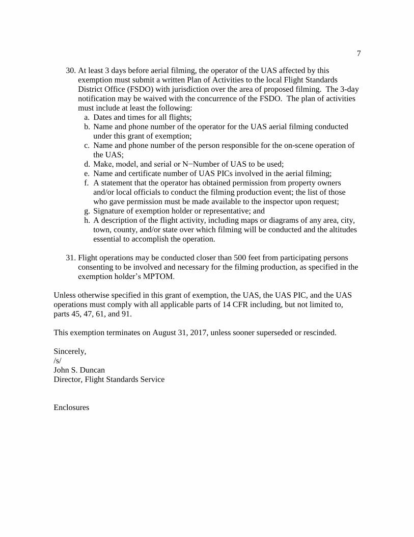
April12, 2015
U.S. Department of Transportation Docket Management System 1200 New Jersey Ave., SE Washington, DC 20590
RE: Exemption Request Section 333 of the FAA Reform Act of 2012
Attachments: 1. Phantom 2 Vision+ User Manual V1.8 January 2015 2. Phantom 2 Vision Plus (Quick Start Guide) 2014-11-18 3. Phantom pilot training guide V1.1 2014-04-07
References: 1. FAA Exemption No. 11138, Regulatory Docket No. FAA-20 14-0481 in the matter of the
petition of DOUGLAS TRUDEAU 2. FAA Exemption No. 11136, Regulatory Docket No. FAA-2014-0508 in the matter of the
petition of ADVANCED AVIATION SOLUTIONS LLC 3. FAA Exemption No. 11 080 Regulatory Docket No. FAA-20 14-0355 in the matter of the
petition of FLYING CAM INC
The name and address of the applicant is:
James M Finch J Finch Photography 9571 Ridgewood Court Bloomington, IL 61705
PH: 309-824-4508 Email: [email protected]
Certified Flight Instructor: 2214388
Commercial Pilot: Airplane Single & Multiengine Land Instrument Airplane Private Privileges: Glider Aero Tow Only
Mechanic: Airframe Powerplant
Dear Sir or Madam,
In accordance with the FAAs Guidelines for Submitting a Petition for Exemption under section 333 of the FAA Modernization and Reform Act of 2012, I James M. Finch, referred to hereafter as the petitioner, request exemption from the following sections of Title 14, Code of Federal
Regulations§§ 61.113(a); 61.113(b); 91.119(c); 91.121; 91.151(a); 91.405(a); 91.407(a)(1); 91.409 (a)(1); 91.409(a)(2); 91.417(a) & (b); In order to operate small unmanned aircraft systems (UAS) commercially in airspace regulated by the Federal Aviation Administration (FAA) for the purposes of aerial photography, cinematography, videography, mapping, crop surveying, inspections and other flight operations that could be performed safely and cost effectively with the use of small UAS at low altitude within the U.S. national airspace. Operations will be performed only at the request of and with the authorization and permission of clients or their authorized agents in order to facilitate commerce and raise awareness of the beneficial uses of small unmanned air systems. So long as such operations are conducted within and under the conditions outlined herein or as may be established by the FAA as required by Section 333. The conditions identified and proposed by the petitioner are drawn from references 1-3.
The Federal Aviation Regulations (FARs) The petitioner seeks exemption from the above mentioned FARs for the following reasons; 61.113(a) & (b); the petitioner requests relief in order to facilitate the utilization of pilots, who hold a PRIVATE PILOT (or greater) certificate. Any pilots operating under this exemption would be required to comply with any conditions as set forth and in a similar fashion to the previously granted exemptions. 91.119(c) As discussed in Exemption 11138 (DOUGLAS TRUDEAU), operations conducted closer than 500 feet to the ground may require that the small UAS be operated closer than 500 feet to essential persons, or objects that would not be possible without additional relief. The petitioner requests modification, waiver or exemption and clarification concerning the terms "congested areas" and "densely populated". The petitioner requests waiver for this condition to allow reasonable and responsible operations in areas of subdivisions and neighborhoods if required. 91.121 As discussed in Exemption 11138 (DOUGLAS TRUDEAU) is inapplicable since the small UAS does not have an altimeter and instead utilizes electronic GPS with a barometric sensor for altitude information. 91.151(a) As discussed in Exemption 11136 (ADVANCED AVIATION SOLUTIONS LLC) prior relief has been granted for manned aircraft to operate at less than the prescribed minimums, including Exemption Nos. 2689, 57 45, and 10650. In addition, similar UAS-specific relief has been granted in Exemption Nos. 8811, 1 0808, and 10673 for daytime, VFR conditions. The UAS provides battery power remaining in percent to the PIC. The small UAS batteries provide approximately 25 minutes of powered flight. Information provided in the operating documents discusses procedures regarding remaining battery power management. Those documents contain a condition in which the PIC will initiate a landing procedure when battery remaining reaches a specified level. Beyond that, the petitioner's small UAS initiates a "Go Home" (to the flight's origination point) when battery level drops to the "Low Battery" level. Given the limitations on proposed operations and the location of those proposed operations, The FAA found that a reduced minimum power reserve for flight in daytime VFR conditions was reasonable. 91.405(a); 91.407(a)(1); 91.409 (a)(1) & (2); 91.417(a) & (b) As discussed in Exemption 11138 (DOUGLAS TRUDEAU), The petitioner proposes to inspect and ensure that the small UAS is in a condition for safe flight in accordance with the operating documents. The FAA found that adherence to the petitioner's operating documents and the conditions and limitations specified, describing the requirements for maintenance, inspection, and record keeping, were sufficient to ensure that safety would not be adversely affected. In addition, the petitioner's own experience as an FAA licensed airframe and powerplant mechanic
qualifies him to determine his craft's airworthiness.
The Petitioner's small UAS The DJI Phantom 2 vision plus is a highly successful consumer grade small rotorcraft in the quadcopter configuration with an advertised weight of less than 44 Ounces (1242g) designed primarily to carry aloft a high definition camera. It has an advertised maximum speed of less than 30 knots (15m/s) and a maximum climb rate of less than 1200 feet per minute (6 m/s). It is powered by four electric motors with a distance between motors of less than 14 inches (350mm) It utilizes an internal inertial measuring unit (IMU) with integrated barometric sensor augmented with global positioning system (GPS) to maintain its geospatial orientation and position. It is controlled primarily through an FCC certified radio control (RC) unit. Real time video and telemetry information is transmitted back to a ground control station allowing the operator and/or PIC to monitor battery level, GPS signal strength, altitude (AGL), distance from PIC, camera imagery, and control camera angle.
Risk mitigation The petitioner's small UAS has failsafe modes of operation for either loss of radio control, GPS signal, or low battery level. Altitude can be limited by the onboard flight controller and maximum altitude can be programmed by the PIC. Battery life limits flight times to approximately 25 minutes. The onboard flight controller will warn the pilot via telemetry and external lighting cues before reaching a low battery state. An automatic termination of flight and landing will be initiated when the battery reaches a predetermined state. It is anticipated that flights will usually last less than 10 minutes. More information is available on pages 41-43 of the attached Phantom 2 Vision plus User Manual version 1.8.
Public interest Use of the UAS in lieu of a manned aircraft would enhance safety and reduce the environmental impact as compared to similar operations conducted with manned aircraft of greater proportions, carrying a crew and flammable fuel. Additionally, use of the small SZUAS in order to facilitate commerce could lead to economic growth. Operations for this petition will enable service for property owners or their designees seeking an enhanced perspective for characteristics, amenities, and benefits of their desired photographic subjects that cannot be displayed through ground level videography/photography. Aerial photography is a valuable marketing tool that can lead to increased commerce and enhance personal photography. Crop surveying applications could lead to decreased use of pesticides and fertilizer and conservation of water as well as increased crop yields and decreased costs. Aerial surveying and inspections can increase work site efficiency, improve volumetric estimations and reduce risks. The petitioner will provide clients with photographic data for these purposes on a 'for hire' basis acting as an independent contractor. Liability insurance will be obtained commensurate with the granting of this request for exemption. Flight data including UAS flight time, Control Unit operation time, incident, accident, and details concerning any deviations from normal operations will be available to FAA for use in collecting data regarding the use of UAS as part of this application. This data may be submitted to FAA via traditional means, e.g. COA Monthly Reports, or other means as required.
Conclusion The petitioner is requesting this exemption for the purposes of news gathering, real estate and general aerial photography. The petitioner's own market research shows pent up demand for these services currently exists in the real estate market and other markets are beginning
to emerge. The petitioner is a freelance photographer with clients in need of these services. A quick internet search demonstrates that many people currently operate similar UAS in exactly this fashion without, it is assumed, FAA authorization. The petitioner refrains from engaging in commercial use of the UAS without FAA authorization. The primary purpose of seeking this exemption is to obtain the capability to offer those services while remaining in compliance. The petitioner understands the needs of his clients and of the FAA. His commercial pilot certificate, Airplane Single & Multiengine Land, and Instrument with private privileges for Glider ensures his knowledge of the airspace in which he will work. His FAA certification as an Airframe & Powerplant mechanic ensures the small UAV will be properly maintained and inspected for airworthiness before flight.
Respectfully submitted
James M Finch DBA J Finch Photography
PH M 2 VISI N+
User Manual
Phantom 2 Vision+ Use1· Manual Vll.l
April 04, 2014
Congratulations on purchasing your new DJI product. Please read this manual carefully before using this product.
We recommend checking the Phantom 2 Vision+ page at www.dji.com for news and updates on everything
from product specs to manual updates. Due to ongoing development, information contained in this manual may
change without notice.
If you have any questions or concerns about your product, please contact your DJI authorized dealer or DJI
Customer Service.
©2014 DJI. All Rights Reserved. 2 (
Using this manual Key
0 Warning
Jl', Important
:r,t Hints and Tips
e. qaf<., c"~c• or Definitions
Important Except when specifically stated, all descriptions In this manual are for Phantom mode, not Naza-M mode.
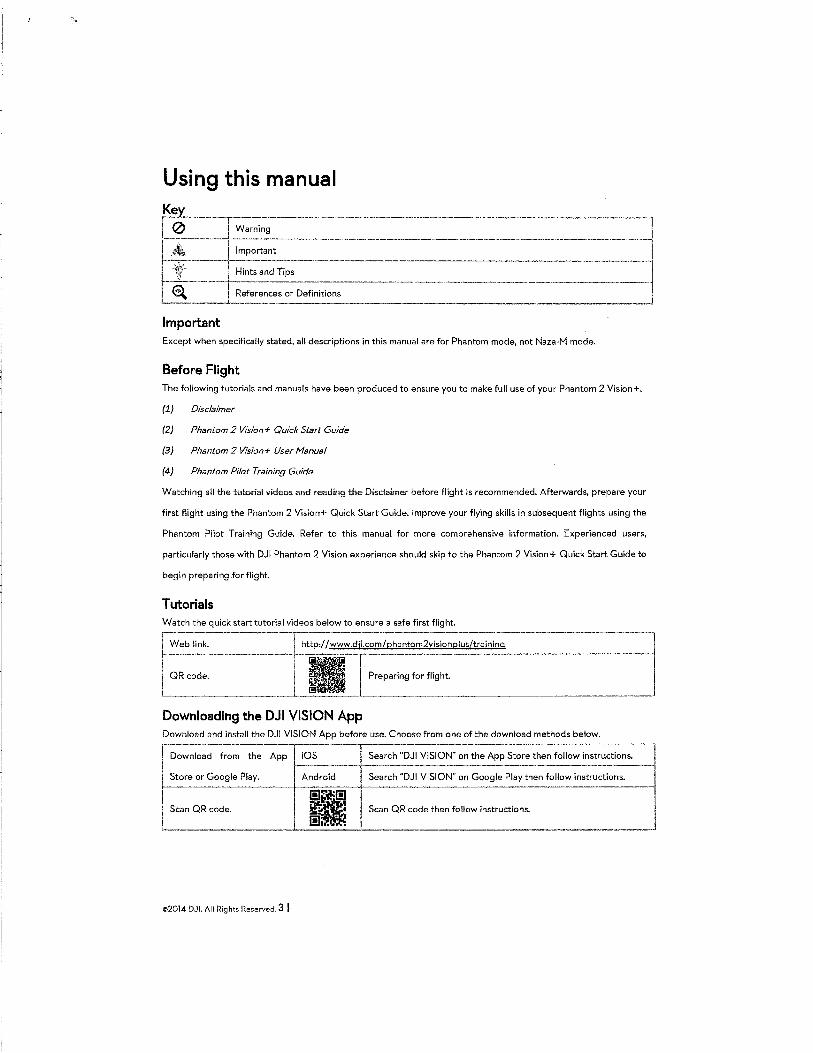
Before Flight The following tutorials and manuals have been produced to ensure you to make full use of your Phantom 2 Vision+.
(1) Disclaimer
(2) Phantom 2 Vision+ Quick Start Guide
(3) Phantom 2 Vision+ User fvfanual
{4) Phantom Pilot Training Guide
Watching all the tutorial videos and reading the Disclaimer before flight is recommended. Afterwards, prepare your
first flight using the Phantom 2 Vision+ Quick Start Guide. Improve your flying skills in subsequent flights using the
Phantom Pilot Training Guide. Refer to this manual for more comprehensive information. Experienced users,
particularly those with DJI Phantom 2 Vision experience should skip to the Phantom 2 Vision+ Quick Start Guide to
begin preparing .for flight.
Tutorials Watch the quick start tutorial videos below to ensure a safe first flight.
---------------------·~ Web link. http:/ /www.dji.com/phantom2visionplus/training I QR code. --~=~~rin-g -fo-r f-li-g-ht-.-------------------~
.__ ___ ·----'----'-'-'-'-'---L ___ _j Downloading the DJI VISION App Download and install the DJI VISION App before use. Choose from one of the download methods below.
Download from the App iOS Search "DJI VISION" on the App Store then follow instructions. r--------t------------------·------------------~
Store or Google Play. Android Search "DJI VISION" on Google Play then follow instructions.
Scan QR code. Scan QR code then follow instructions.
©2014 DJI. All Rights Reserved. 3 J
Contents USING THIS lv!ANUAL .............. __ .... ,_,,_,,, ........... --.......... __ ,,, ............................. _ ....... _ ........................ - .. -·-·------···--3
KEY ........................................................................................................................................................................................................................ 3 IMPORTANT .......................................................................................................................................................................................................... 3
BEFORE FLIGHT .................................................................................................................................................................................................. 3
TUTORIALS ..•..•.••..••.•••••.•••.......•......•.....•..•..••••..•.••.••..••••.•..••.•••..•...•...•••••••.••.••.••..••....•...•...••...........•..•••..•.....•••••••••••••••...••.•••..•..•..••.....••.•..•••.•••.••• 3
DOWNLOADING THE DJI VISION APP ......................................................................................................................................................... 3
CONTENTS ................ - ....... _,,_,,, ......... ------··--···-·-·-·-··-···-·· .. ······-·· .. ·· .. ···-··-·---·---·-···-··--········-·----·----4 OVERVIEW ...... _____ ,_, ....... -·-·--------............... _, _______ , ................... _ .. ________ ,_, __ , ............................ __ .. 7 liN THE BOX ............................................... - ............ - ................. - ............................................. - ............. __ .,, ............................... 7 2 INTRODUCTION ....... , .... ___ ,, ..................... _. ____ ,, ..................................................................... _ .. _ .. ,_, ___ ,_, ................ 9 ASSE!v!BL Y AND USE ........ ___ , ................................... --...................... - .. _ .... , .. ___________ , ..... ,_., ___ . __ , _____ ,_10 1 REMOVING GIMBAL CLA!v!P_ .. ,_,_, ___ ,,_,, ... _, .. ,, .... , __ ,,, ................................. - ............. - ....................... ___ .. ,, ... 10 2 PREPARING THE BATTERY ,_, ___ .... _ .............................. __ ._ ............................................................ __ ,_, .................. 10
2.1 DJI SMART FLIGHT BATTERY ................................................................................................................................................................... 10
2.2 USAGES .......................................................................................................................................................................................................... 11
Powering on/off. ......................................................................................................................................................................................... 77 Checking the battery level... ................................................................................................................................................................... 77 Battery life .................................................................................................................................................................................................... /2
2.3 CHARGING THE FLIGHT BATTERY ........................................................................................................................................................... 13
2.4 BATTERY INSTALLATION ........................................................................................................................................................................... 13
2.5 CORRECT BATTERY USAGE NOTE$ ........................................................................................................................................................ 14
3 PREPARING THE PHANTOM 2 VISION+ .............. - .... _ ..................................... _ ....... _ ............................................... --..... 15 3.11NTRODUCTION ............................................................................................................................................................................................ 15
32 BUILT-IN FLIGHTCONTROLSYSTEM ...................................................................................................................................................... 15
FC Assistant Port ...................................................................................................................................................................................... 76 3.3 LED FLIGHT INDICATOR DESCRIPTIONS ............................................................................................................................................... 16
3.43-AXIAL STABILIZED GiMBAL ................................................................................................................................................................... 17
Anti-drop Kit ................................................................................................................................................................................................ 77 Micro-SD Slot... ........................................................................................................................................................................................... 78 Gimbal Error Warning ............................................................................................................................................................................. 18
3.5 CAMERA ....................................................................................................................................................................................................... 19
Lens cap removaL .................................................................................................................................................................................... 79 Camera Function Buttons .................................................................................................................................................................... 20 Camera Data Port ................................................................................................................................................................................... 20 Camera LED Indicator ........................................................................................................................................................................... 20
4 ATTACHING THE PROPELLERS_, .................... _., ... _,_,_._,,_ .... , ........................... - ......... ---·-·-·--.............. _ 21 4.11NTRODUCTION ............................................................................................................................................................................................ 21
4.2 ASSEMBLY .................................................................................................................................................................................................... 21
4.3 REMOVING THE PROPELLERS .................................................................................................................................................................. 21
4.4 NOTES ......................................................................................................................................................................................................... 22
5 PREPARING THE REMOTE CONTROLLER--...................... - ......... _ .... , .. , .... _ ....... - ............ _______ , __ ,_, ___ 23 5.1 THE REMOTE CONTROLLER ..................................................................................................................................................................... 23
5.2 POWER ON THE REMOTE CONTROLLER .............................................................................................................................................. 23
5.3 REMOTE CONTROLLER POWER LED STATUS INFORMATION ......................................................................................................... 24
5.4 ANTENNA 0RIENTATION ......................................................................................................................................................................... 24
5.5 REMOTE CONTROLLER 0PERATION ..................................................................................................................................................... 25
5.6 LINKING THE REMOTE CONTROLLER AND RECEIVER ........................................................................................................................ 26
Linking Procedures .................................................................................................................................................................................. 27 Link lndicator ............................................................................................................................................................................................. 27
5.7 COMPLIANCE VERSION CONFIGURATION ........................................................................................................................................... 27
6 PREPARING THE RANGE EXTENDER---........... - ....................... _,_,_ ...................... _ .. , ___ , ___ , __ , ______ ....... 29 6.11NTRODUCTION ........................................................................................................................................................................................... 29
SYSTEM lndicator .................................................................................................................................................................................... 29
©2014 DJI. All Rights Reserved. 4 I
POWER lndicator .................................................................................................................................................................................... -29 Binding Reset Button .............................................................................................................................................................................. 29
6.2 USE .............................................................................................................................................................................................................. 30 Charging the Range Extender ............................................................................................................................................................ 30 Powering on the Range Extender ..................................................................................................................................................... 30 Checking the Battery Level ................................................................................................................................................................. 30
6.3 RENAMING THE RANGE EXTENDER SSID ............................................................................................................................................ 30 6.4 BINDING THE PHANTOM 2 VISION+ AND RANGE EXTENDER ............................................................................................................ 31
7 DOWNLOADING AND INSTALLING THE DJI VISION APP ............................................................................................... 33 7.1 DOWNLOAD AND INSTALL ........................................................................................................................................................................ 33 7.2 REGISTER AND LOGIN ............................................................................................................................................................................... 33
[7] Register .................................................................................................................................................................................................. 33 [2] Login ...................................................................................................................................................................................................... .34 [3] Usage tips ............................................................................................................................................................................................. 34
8 CONNECTING THE CAMERA ........................................................................................................ - ....................................... 35 8.1 CONNECTING PROCEDURES .................................................................................................................................................................... 35
Wi-Fi Connection Indicator Description .......................................................................................................................................... 36 FLIGHT ................................................................................................................................................................................................... 37
Flight Environment Requirements ..................................................................................................................................................... 37 Preflight Checklist.. ................................................................................................................................................................................. 37
1 CALIBRATING THE COMPASS ................................................................ '" ................................................................................. 38 1.1 CALIBRATION PROCEDURES ................................................................................................ , .................................................................... 38
1.2 WHEN TO RECALIBRATE ........................................................................................................................................................................... 38
2 STARTING/STOPPING THE MOTORS ..................................................................................................................................... 39 2.1 STARTING MOTORS .................................................................................................................................................................................... 39
2.2 STOPPING MOTORS .................................................................................................................................................................................. 39
3 FLIGHT TEST .................................................................................................................................................................................... 40 3.1 TAKE OFF/LANDING PROCEDURES ....................................................................................................................................................... 40
3.2 VIDEO SUGGESTIONS AND TIPS ............................................................................................................................................................ 40
4 FAILSAFE FUNCTION _ ................................................................................................................................................ - .......... 41 4.1 WHEN WILL FAILSAFE ACTIVATE? ........................................................................................................................................................... 41 4.2 FAILSAFE PROCEDURE .............................................................................................................................................................................. 41
Failsafe on the DJI VISION App ......................................................................................................................................................... 42 4.3 REGAINING CONTROL DURING FAILSAFE PROCEDURES ................................................................................................................ ..42
5 LOW BATTERY LEVEL WARNING FUNCTION ........... _ ..................................................................................................... -43 Low Battery Level Warning on the DJI VISION App ................................................................................................................. 43
6 FLIGHT LIMITS ................................................................................................................................................................................. 44 6.1 MAX HEIGHT & RADIUS LIMITS ............................................................................................................................................................... 44
6.2 FLIGHT LIMITS OF SPECIAL AREAS ........................................................................................................................................................ 45 6.3 CONDITIONS OF FLIGHT LIMITS ............................................................................................................................................................ 46
6.4 DISCLAIMER ................................................................................................................................................................................................ 47 DJI VISION APP USAGE _, ................................................... - ........................................................................ - ........................ 48 1 OJI VISION APP MAIN MENU .... _____ ................................................................................................................................ 48 2 CAMERA PAGE ..................................................................................................................................................... ; .......................... 49
[1] RETURN ........................................................................................................................................................................................................ 49 [2] CAMERA PITCH CONTROL. ..................................................................................................................................................................... 49
Normal Mode ............................................................................................................................................................................................ 49 Accelerometer Sensor Mode .............................................................................................................................................................. 50
(3] FLIGHT ATTITUDE AND RADAR FUNCTION .......................................................................................................................................... 50 (4] FLIGHT PARAMETERS ....................................... , ......................................................................................................................................... 51 [5] W1-F1 SiGNAL INTENSITY ........................................................................................................................................................................... 51 [6] FLIGHT BATTERY LEVEL ............................................................................................................................................................................. 51
[7] AIRCRAFT GPS STATUS ............................................................................................................................................................................ 52 [8] MICRO-SD CARD STATUS ........................................................................................................................................................................ 52 [9] RANGE EXTENDER BATTERY LEVEL ....................................................................................................................................................... 52
<l>2014 DJI. All Rights Reserved. 5 I
[10] REMAINING SHOTS ............................................................................................................................................................ , ..................... 52 [11] SHUTTER BUTTON .................................................................................................... , ................................................................................ 52 [12] VIDEO RECORDING BUTTON .................................... , ............................................................................................................................ 52 [13] CAMERA SETTINGS ................................................................................................................................................................................... 53 [14] HIDE OR SHOW FLIGHT PARAMETERS ................................................................................................................................................. 53
3 CAMERA SETTINGS ....................................................................................................................................................................... 54 [1] CAPTURE MODE .......................................................................................................................................................................................... 54 [2] PHOTO SIZE ........................................................................................................................................................ , ....................................... 54 [3] VIDEO RESOLUTION ................................................................................................................................................................................ ,.54 [4] PHOTO FORMAT ........................................................................................................................................................................................ 55 [5] SELECTABLE ISO .............................................................................................................. , ........................................................................ 55 [6] WHITE BALANCE ........................................................................................................................................................................................ 55 [7] EXPOSURE METERING ............................................................................................................................................................................... 55 [8] EXPOSURE COMPENSA TION .................................................................................................................................................................... 55 [9] SHARPNESS ................................................................................................................................................................................................. .56 [10] ANTI-FliCKER ........................................................................................................................................................................................... .56 [11] RESTORE DEFAULT SETTINGS ................................................................................................................................................................ .56 [12] FORMAT MICRO-SD CARD .................................................................................................................................................................... 56
4 ALBUM PAGE ................................................................................................................................................................................... 57 4.1 SD CARD ALBUM ................... , ................................................................................................................................................................... 57 4.2 MOBILE DEVICE ALBUM ........................................................................................................... , .............................................................. 59
5 NEWS PAGE .............................................................................................................................................. _.. ................................... 61 6 SETTINGS PAGE .............................................................................................................................................................................. 62
[1] TOOLBAR AUTO HIDE ................................................................................................................................................................................ 62 [2] WHEN CONNECTION LOST ..................................................................................................................................................................... 62 [3] CAMERA SETTINGS DISPLAY .................................................................................................................................................................... 63 [4] PREVIEW QUALITY ..................................................................................................................................................................................... 63 [5] PARAMETER UNIT ...................................................................................................................................................................................... 64 [6] FPV MODE ................................................................................................................................................................................................ 64 [7] AUTO FLIPS ................................................................................................................................................................................................ 64 [8] BATTERY LOWWARNING ....................................................................................................................................................................... 64 [9] TUTORIAL .................................................................................................................................................................................................... 64 [10] CLEAR NEWS CACHE ............................................................................................................................................................................ 64 [11] BINDING ...................................................................................................................................................................................................... 64 [12] RENAMESSIDOF RANGE EXTENDER ................................................................................................................................................. 64 [13] FIND MY PHANTOM 2 VISION ......................................................................................................................................................... 65 [14] ACCOUNT .................................................................................................................................................................................................. 65 [15] RATE ............................................................................................................................................................................................................ 65 [16] ABOUT ........................................................................................................................................................................................................ 65
ASSIST ANT SOFTWARE ................................................................................................................................................................... 66 liNST ALLING DRIVER AND PHANTOM 2 VISION+ ASSIST ANT SOFTWARE ................................................................. 66
1.11NSTALLING AND RUNNING ON WINDOWS ............................................................................................................................................ 66 1.21NSTALLING AND RUNNING ON MAC OS X .......................................................................................................................................... 66
2 USING ASSISTANT SOFTWARE ................................................................................................................................................. 68 2.1 USING THE PHANTOM 2 VISION+ ASSISTANT SOFTWARE .................................................................................................................. 68 2.2 FIRMWARE UPGRADE OF THE PHANTOM 2 VISION+ .......................................................................................................................... 69 2.3 USING THE PHANTOM RC ASSISTANT SOFTWARE ......................................................................................................................... 69
APPENDIX. ............................................................................................................................................................................................. 71 1 REAR LED FLIGHT INDICATOR STATUS ......................................................................................................................... _.. ..... 71 2 SPECIFICATIONS ............................................................................................................................................................................ 72 3 TROUBLESHOOTING (FAQ) ....................................................................................................................................................... 73
©2014 DJI. All Rights Reserved. 6 I
Overview The Phantom 2 Vision+ is the next evolution of the Phantom 2 Vision. It features the same App enabled First
Person View (FPV), high performance camera, remote camera control and in-flight content sharing, but adds to it a
high performance 3- axial camera stabilization system. It is ideal for aerial creativity whether photo or video.
€\ FPV: First Person View, see the world from the perspective of the craft and feel a true flying experience.
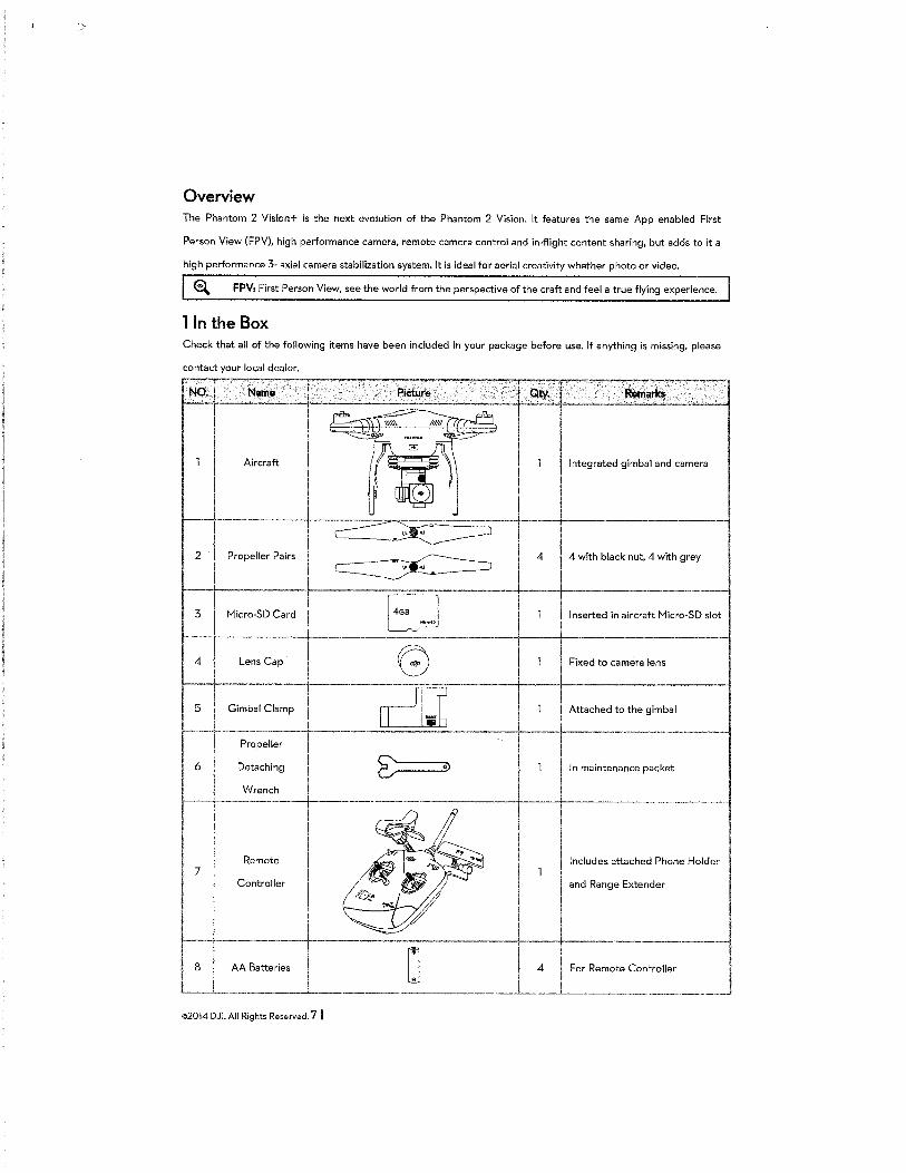
lin the Box Check that aU of the following items have been included in your package before use. If anything is missing, please
NO; I
Integrated gimbal and camera
·--+-----------
2 Propeller Pairs 4 4 with black nut, 4 with grey
Inserted in aircraft Micro-SD slot
·------~----~------------------
Fixed to camera lens
·-~--!----------------
6
Remote Includes attached Phone Holder 7
Controller and Range Extender
-t 8 I AA Batteries
I , ----..l..---·-------.L..----··-------------·--·-
4 For Remote Controller
. .L.... ________________ . ___ .
©2014 DJI. All Rights Reserved. 7 I
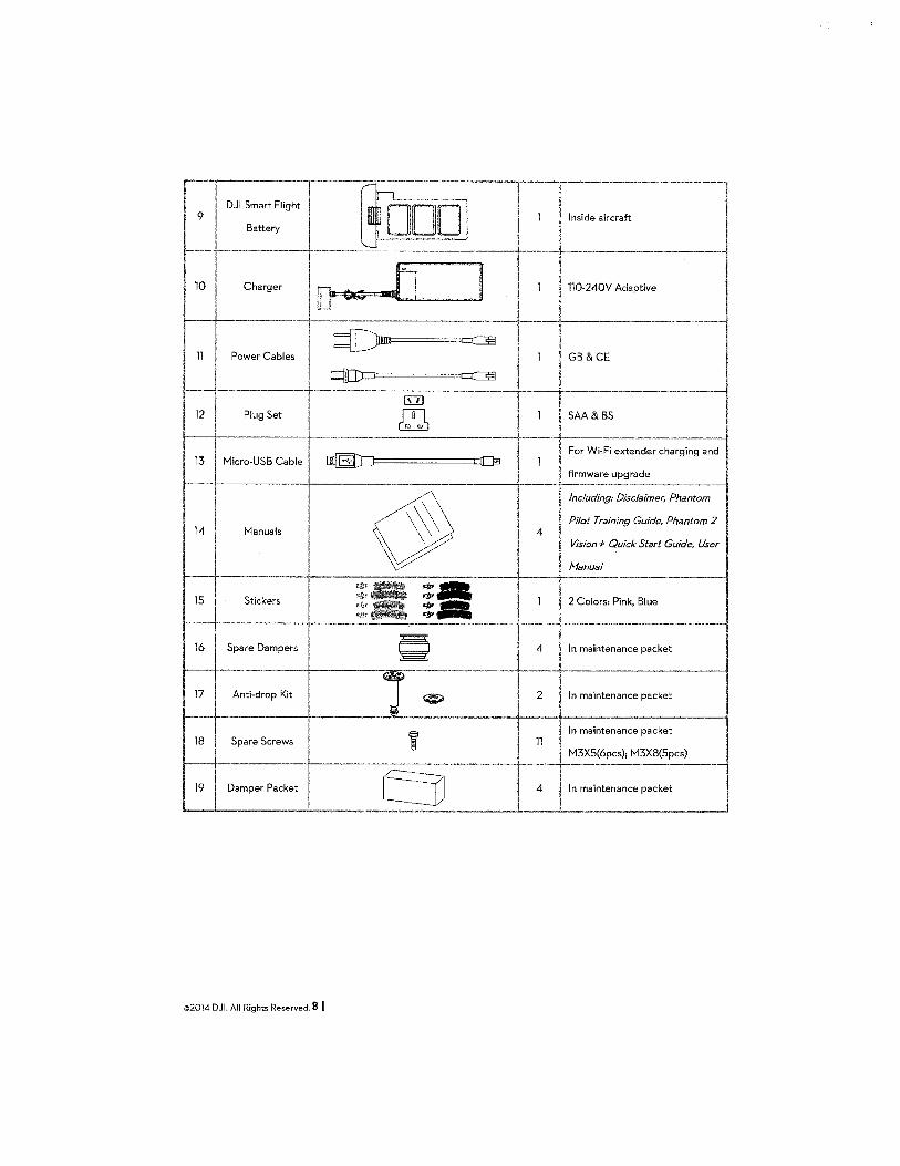
r---r--- 1 [t----·---·---r--T~~ dJI :::~':j __ ~qQQJ__j__1ll~:~~ air::~-----·--10 J' c""""' [ ~.Jl ] I 1 H0-240V Ad•p<W•
jLCJ + I ~---r-11 Iii ---+,,--~--I -1---+----·--·--
Power Cables GB & CE
~-·---P-Iu_g_S-et-- ---~----·-DJ,-~---...... -----+--1--+-S-A_A_&_B_S ___________ _
-+-11_ 0 "' ·-----+-----1---·-----------.. --For Wi-Fi extender charging and
-
13_ .. --LI Micro-USB Cable I ~-- 1 firmware upgrade --------------+-----+-------
1 " Including: Disclaimer. Phantom
14 I Manuals I \~
4 I Pilot Training Guide, Phantom 2 J I \
1 ~~ ::::a~ Quick Start Guide, User
I ---j-------;; Jla q, ..
--~~---l- ----~:c~:~~ .. --1 ________ --~;·-~----;~---------- --~--+-~~ol:=_:~~:-~~~: .......... --------·-. I I
~~ Sp•~• ""_mp+------ ~-------~ -~n maintenance·-p-ac_k_e_t-------1
17 A"ll-d'op Kll 1 U ® 2 '" m•'"m"""'' p•<k•< -- ------r ~ - ~~--~-maintenance packet 18 Spare Screws J 13 11
I J I M3X5(6pcs); M3X8(5pcs)
~~~Dampe~:cket .I -----B --r-:~'" .. "'"~'"'"' I I .
--
©2014 DJI. All Rights Reserved. 8 (
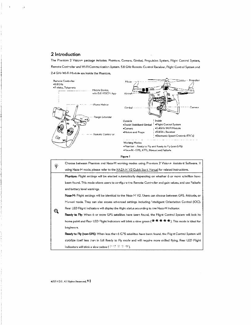
2 Introduction The Phantom 2 Vision+ package includes: Phantom, Camera, Gimbal, Propulsion System, Flight Control System,
Remote Controller and Wi-Fi Communication System. 5.8 GHz Remote Control Receiver, Flight Control System and
2.4 GHz Wi-Fi Module are inside the Phantom.
Remote Controller •5.8GHz •2 sticks, 7 channels
Mobile Device, with DJI VISION App
"·'· Phone Holder
Range Extender
Remote Controller
Outside l Inside
•3-axial Stabilized Gimbal : •Flight Control System
•Camera ; •2.4GHz Wi~Fi Module
•Motors and Props ; •5.8GHz Receiver
: •Electronic Speed Controls (ESCs)
Working Nodes
•Phantom- Ready to Fly and Ready to Fly (non-GPS)
•Naza-N · GPS, A TTl., Manual and Failsafe
Figure 1
Choose between Phantom and Naza-M working modes using Phantom 2 Vision+ Assistant Software. If
using Naza-M mode, please refer to the NAZA·M V2 Quick Start Manual for related instructions.
Phantom: Flight settings will be elected automatically depending on whether 6 or more satellites have
been found. This mode allows users to configure the Remote Controller and gain values, and use Failsafe
and battery level warnings.
Naza-M: Flight settings will be identical to the Naza-M V2. Users can choose between GPS, Attitude, or
Manual mode. They can also access advanced settings including Intelligent Orientation Control (IOC).
Rear LED Flight Indicators will display the flight status according to the Naza-M indicator.
Ready to Fly: When 6 or more GPS satellites have been found, the Flight Control System will lock its
home point and Rear LED Flight Indicators will blink a slow green ( ilil ilil S Ill $).This mode is ideal for
beginners.
Ready to Fly (non-GPS): When less than 6 GPS satellites have been found, the Flight Control System will
stabilize itself less than in full Ready to Fly mode and will require more skilled flying. Rear LED Flight
Indicators will blink a slow yellow ( ).
<>2014 DJI. All Rights Reserved. 9 I
Assembly and Use Follow the below instructions to prepare for flight.
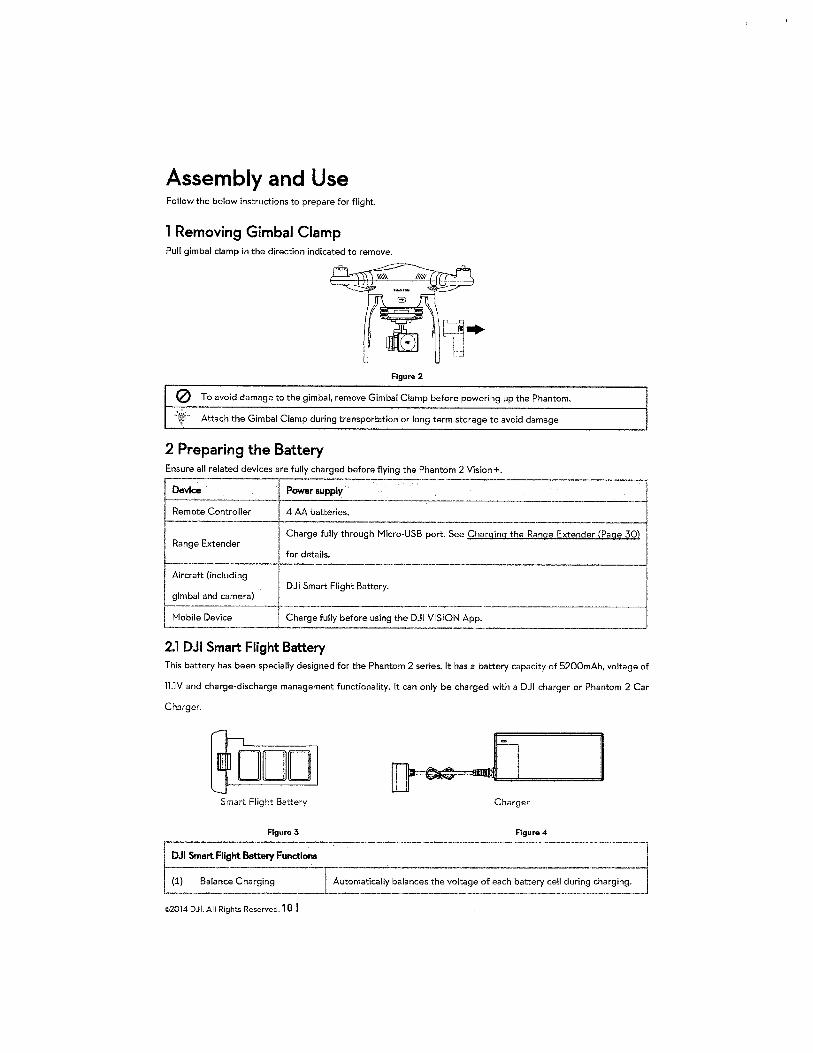
1 Removing Gimbal Clamp Pull gimbal clamp in the direction indicated to remove.
Figure 2
0 To avoid damage to the gimbal, remove Gimbal Clamp before powering up the Phantom.
-:~~~i·· Attach the Gimbal Clamp during transportation or long term storage to avoid damage
2 Preparing the Battery Ensure all related devices are fully charged before flying the Phantom 2 Vision+. r-
--1 Device Power supply
-·--·-----MH ____ ·--Remote Controller 4 AA batteries. ----· - ----
Charge fully through Micro-USB port. See Charging the Range Extender (Page 30) Range Extender
for details.
Aircraft (including DJI Smart Flight Battery.
gimbal and camera) !-----·---·--"
Mobile Device Charge fully before using the DJI VISION App. '---
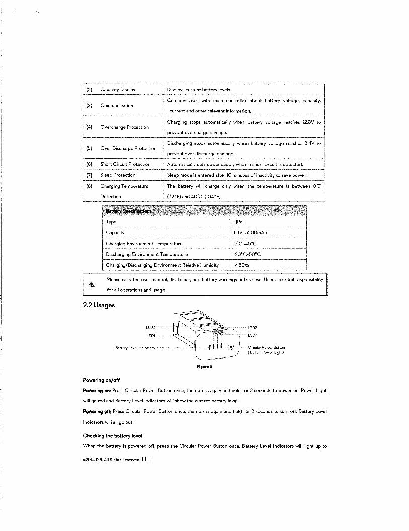
2.1 DJI Smart Flight Battery This battery has been specially designed for the Phantom 2 series. It has a battery capacity of 5200mAh, voltage of
ll.lV and charge-discharge management functionality. It can only be charged with a DJI charger or Phantom 2 Car
Charger.
D Smart Flight Battery Charger
Figure 3 Figure 4
DJI Smart Flight Battery FunctiOil$
Balance Charging I Automatically balances the voltage of each battery cell during
©2014 DJI. All Rights Reserved. 10 I
I (2)
---·-....,----------------·--------Capacity Display 1 Displays current battery levels.
~mmunicates with ~ai~ co_n_t-ro-1-le_r_a-bo.ut battery
I current and other relevant information.
I Charging stops automatically when battery voltage reaches 12.8V to 1
(3) Communication
(4) Overcharge Protection 1 I 1
-i- prevent overcharge damage. 1
r----------·----· · Dis;;;;~rging stop:::omatically when batter~hes 8.4V ~l ! (5) Over Discharge Protection i ~---------------- prevent over discharge damage. ________ _!
(7) Sleep Protection Sleep mode is entered after 10 minutes of inactivity to save power. ~
{8) Charging Temperature I The battery will charge only when the temperature is between O"C
L_ Detection I (32"F)and40"C (104"F).
Type UPo
Capacity ll.lV, 5200mAh
Charging Environment Temperature 0°C-40"C
Discharging Environment Temperature -20°C-50°C
Charging/Discharging Environment Relative Humidity <80%
Please read the user manual, disclaimer, and battery warnings before use. Users take full responsibility
for all operations and usage.
2.2 Usages
LED2
LEDl
Batlery Level Indicators
Powering on/off
Figure 5
Circular Power Sulton { Built-in Power Light)
Powering on: Press Circular Power Button once, then press again and hold for 2 seconds to power on. Power Light
will go red and Battery Level Indicators will show the current battery level.
Powering off: Press Circular Power Button once, then press again and hold for 2 seconds to turn off. Battery Level
Indicators will all go out.
Checking the battery level
When the battery is powered off, press the Circular Power Button once. Battery Level Indicators will light up to
©2014 OJ I. All Rights Reserved. 11 I
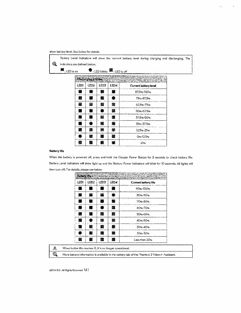
show battery level. See below for details.
Battery Level Indicators will show the current battery level during charging and discharging. The
E.l indicators are defined below.
II: LED is on • : LED blinks ill : LED is off
LEDi LED2 LED3 LED4 Current battery level
• • • • 87.5%·100%
Ill • • • 75%-87.5%
• • II • 62.5%-75%
Ill Ill • • 50%·62.5%
Ill II Ill Ill 37.5%-50%
• • Ill • 25%-37.5%
• Ill • • 12.5%-25%
• II • • 0%·12.5%
• Ill • • <0°/o
Battery life
When the battery is powered off, press and hold the Circular Power Button for 5 seconds to check battery life.
Battery Level Indicators will show light up and the Battery Power Indicators will blink for 10 seconds. All lights will
then turn off. For details, please see below.
LED1 lED2 LED3 LED4 Current battery life
Ill Ill Ill Ill 90%·100%
II • • • 80%·90%
Ill Ill Ill Ill 70%·80%
Ill Ill • • 60%·70%
Ill Ill • Ill 50%·60%
• • • • 40%-50%
• • • Ill 30%·40%
• Ill Ill Ill 20%-30%
Ill • • Ill Less than 20%
When batter life reaches 0, it is no longer operational.
~ More battery information is available in the battery tab of the Phantom 2 Vision+ Assistant.
©2014 DJI. All Rights Reserved. 12 I
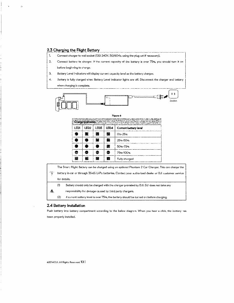
f,~-QI~~~~~~~::e~~~~~ s~;k~~~~;~~. 50/6;~;,-~~:~ t~:~~-;~:~;7~::::~~):---------------l I 2. Connect battery te charger. If the current capacity of the battery is over 75%, you should turn it on I
I before beginning to charge. j
3. Battery Level Indicators will display current capacity level as the battery charges. I
l4_ ;;~~,:::_::;.:: -~ l~•l lodi~Wc "gh~ ore off D&ooo~ '"" ohocgoc ood -~ I
.,G Socket
Figure6
LEDl LED2 LED3 LED4 Current battery level
• II II • 0%-25%
• • Ill Ill 25%-50%
• • • Ill 50%-75%
• • • • 75%-100%
Ill Ill Ill Ill Fully charged
The Smart Flight Battery can be charged using an optional Phantom 2 Car Charger. This can charge the
battery in-car or through 35-65 Li-Po batteries. Contact your authorized dealer or DJI customer service
for details.
(1) Battery should only be charged with the charger provided by DJI. DJI does not take any
responsibility for damage caused by third party chargers.
(2) If current battery level is over 75%, the battery should be turned on before charging.
2.4 Battery Installation Push battery into battery compartment according to the below diagram. When you hear a click, the battery has
been properly installed.
©2014 DJI. All Rights Reserved. 13 I
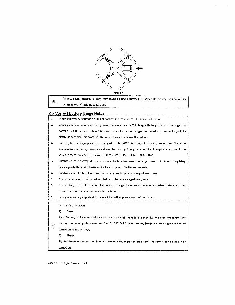
Figur& 7
An incorrectly installed battery may cause (1) Bad contact, (2) unavailable battery information, (3)
unsafe flight, (4) inability to take off.
2.5 Correct Batte~ Usage Notes _ . ·------, 11. VVhen the battery is turned on, do not connect it to or disconnect it from the Phantom.
I 2. Charge and discharge the battery completely once every 20 charge/discharge cycles. Discharge the
I battery until there is less than 8% power or until it can no longer be turned on, then recharge it to
maximum capacity. This power cycling procedure will optimize the battery.
3. For long term storage, place the battery with only a 40-50% charge in a strong battery box. Discharge
and charge the battery once every 3 months to keep it in good condition. Charge amount should be
varied in these maintenance charges - (40%-50%}-0°/o-l00%--{40o/o-50%).
4. Purchase a new battery after your current battery has been discharged over 300 times. Completely
discharge a battery prior to disposal. Please dispose of batteries properly.
Purchase a new battery if your current battery swells up or is damaged in any way. 5.
6. Never recharge or fly with a battery that is swollen or damaged in any way. 1
I Never charge batteries unattended. Always charge batteries on a non-flammable surface such as ! l
concrete and never near any flammable materials. I Safety is extremely important. For more informatio~, please s:.:_ the Disclaimer_. __________ j
! 7.
I La.
Discharging methods:
1) Slow
Place battery in Phantom and turn on. Leave on until there is less than 8% of power left or until the
battery can no longer be turned on. See DJI VISION App for battery levels. Motors do not need to be
turned on, reducing wear.
2) Quick
Fly the Phantom outdoors until there is less than 8% of power left or until the battery can no longer be
turned on.
©2014 DJI. All Rights Reserved. 14 I
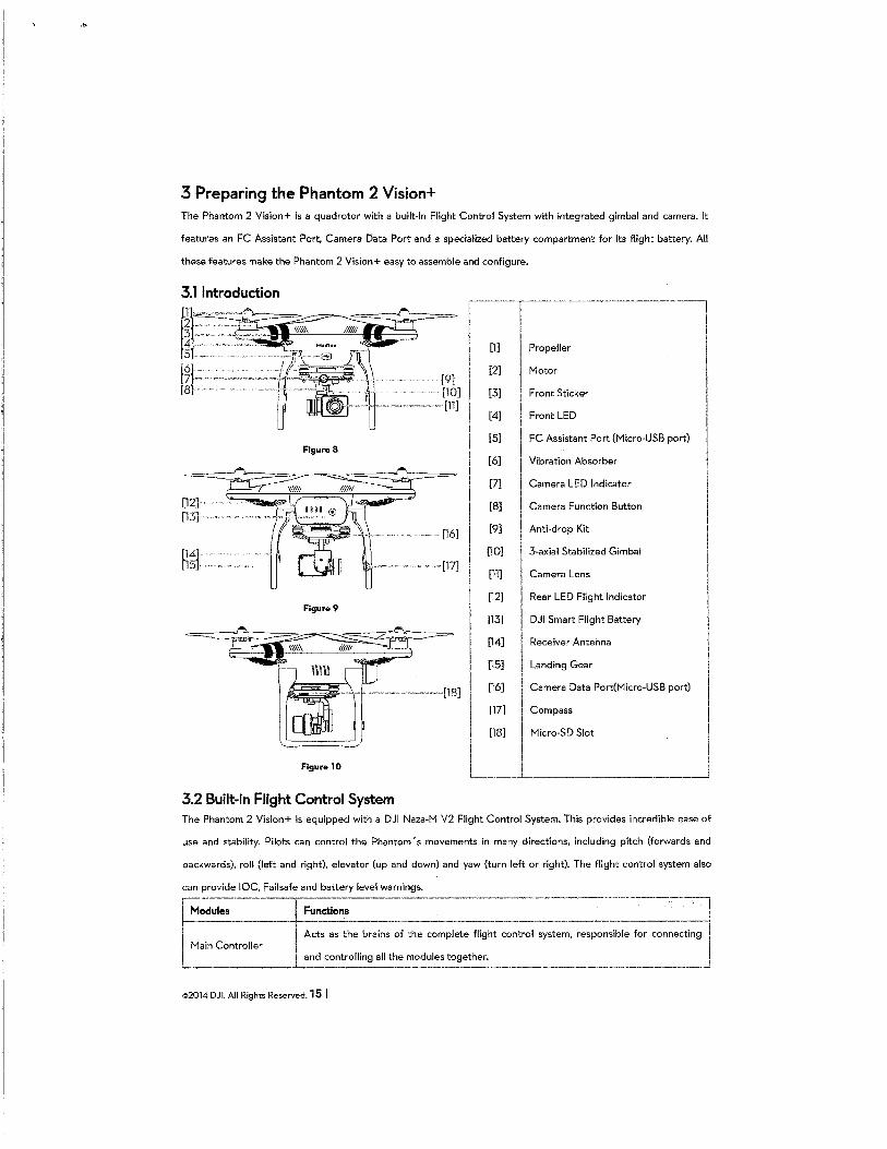
3 Preparing the Phantom 2 Vision+ The Phantom 2 Vision+ is a quadrotor with a built-in Flight Control System with integrated gimbal and camera. It
features an FC Assistant Port, Camera Data Port and a specialized battery compartment for its flight battery. All
these features make the Phantom 2 Vision+ easy to assemble and configure.
[12]. [13]
[14] [15]-
Figure 9
[9] [10]
' [ll]
[17]
[18]
~----------------~
I I I 1 [1] I Propeller I I ~ Mo~ I
~1., [3] I Front Sticker
[4] Front LED
[5]
[6]
[7]
[8]
[9]
[10]
[11]
[12]
[13]
[14]
[15]
[16]
[17]
[18]
FC Assistant Port (Micro-USB port)
Vibration Absorber
Camera LED Indicator
Camera Function Button
Anti-drop Kit
3-axial Stabilized Gimbal
Camera Lens
Rear LED Flight Indicator
DJI Smart Flight Battery
Receiver Antenna
Landing Gear
Camera Data Port(Micro-USB port)
Compass
Micro-SD Slot
I I I I Figure 10 L ___j
3.2 Built-in Flight Control System The Phantom 2 Vision+ is equipped with a DJI Naza-M V2 Flight Control System. This provides incredible ease of
use and stability. Pilots can control the Phantom's movements in many directions, including pitch (forwards and
backwards), roll (left and right), elevator (up and down) and yaw (turn left or right). The flight control system also
can provide IOC, Failsafe and battery level warnings.
~~-ules ------
1 Main Controller
Functions
Acts as the brains of the complete flight control system, responsible for connecting
L and controlling all the modules together. ------~-----------------------------------~
©2014 OJ I. All Rights Reserved. 15 I
~-~MU ------tl ~:; ~.::~" loocti•l ••~or ~~=~~~~~: bo>h •:j I The compass reads geomagnetic information and assists the GPS (Global Position II
I GPS & Compass 1 L System) to accurately calcula~~the ~~ion~nd height of the aircraft. i
LLED Flight Indicators Indicates the status of flight control system. --------------~ FC A$Sistant Port
The flight control system communicates with the PC Assistant Software through a Micro-USB cable between the
Phantom FC Assistant Port and the PC. Users can use Assistant Software to configure the aircraft and upgrade the
Phantom firmware. Please refer to Using the Phantom 2 Vision+ Assistant Software (Page 68) for details.
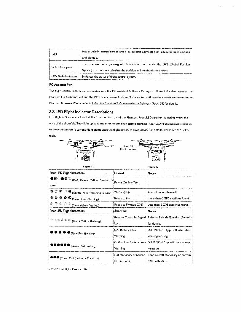
3.3 LED Flight Indicator Descriptions LED flight indicators are found at the front and the rear of the Phantom. Front LEDs are for indicating where the
nose of the aircraft is. They light up solid red after motors have started spinning. Rear LED Flight Indicators light up
to show the aircraft's current flight status once the flight battery is powered on. For details, please see the below
table.
Figurell Figure 12
----=fotes l I --------~
• : .. :': V ft (Green, Yellow flashing in turn) -·---·--· I Aircraft cannot take off. ----1 ta-i----- ·--- ------ .------·-] ~· •• II 0 (Slow Green flashing) More than 6 GPS satellites found. 1
L ___ ::\ --;::~w flashing) Re~~~Fiy (~-GPSl__ Less tha~-~?s satellites foun~=l !Rear LED Flight Indicators ~- Notes . j c= \Remote Controller Signal Refer to Failsafe Function (Pag~ I · (Quick Yellow flashing) ~ I I Lost for details. ~------------------- --------· --------------··---1
I . I Low Battery Level DJI VISION App will also show!
• e ••• (Slow Red flashing) I I . I Warning warning message.
fl ;~.-;~-;~Qu:~ Red fl=~ing)-------j-~ritical L~:-~~~ery -;:~~ DJ~~ION A;p will sho:-war,;;-;;~~ Warning message. ,
------+1-N_ormal
(Red, Green, Yellow flashing
-----+----- ·-·-------···------·-] '1· _jNot Stationary o.r Sensor Keep aircraft stationary or perform I,
••• (Three Red flashing off and on) l ~ias is t~~ bi~----- IMU calibrati~ ___ __j
©2014 DJL All Rights Reserved. 16 I
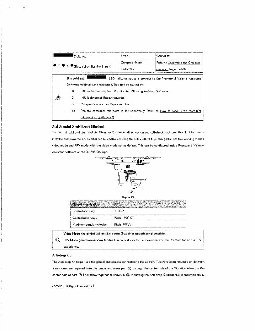
,.--.. --~olid :;-·----·--·~or*----·---·lCannot fly. I r-------... --.. ·----·--·-·-------,I'Comp:Ss Ne:~---- ~~;:;:~-:;~;:~~~;~~~;::l I• • • (Red, Yellow flashing in turn) j
Calibration (Page38) to get details. , L ___________ .. ___ --- ---~-------·--··-----·------'
If a solid red LED indicator appears, connect to the Phantom 2 Vision+ Assistant
Software for details and resolution. This may be caused by:
1) IMU calibration required: Recalibrate IMU using Assistant Software.
2) IMU is abnormal: Repair required.
3) Compass is abnormal: Repair required.
4) Remote controller mid-point is set abnormally: Refer to How to solve large margin(s)
mid-point error (Page 73).
3.4 3-axial Stabilized Gimbal The 3-axial stabilized gimbal of the Phantom 2 Vision+ will power on and self-check each time the flight battery is
installed and powered on. Its pitch can be controlled using the DJI VISION App. This gimbal has two working modes,
video mode and FPV mode, with the video mode set as default. This can be configured inside Phantom 2 Vision+
Assistant Software or the DJI VISION App.
Figure 13
Video Mode: the gimbal will stabilize across 3-axial for smooth aerial creativity.
~ FPV Mode (First Person View Mode): Gimbal will lock to the movements of the Phantom for a true FPV
experience.
Anti-drop Kit
The Anti-drop Kit helps keep the gimbal and camera connected to the aircraft. Two have been mounted on delivery.
If new ones are required, take the gimbal and press part ® through the center hole of the Vibration Absorber the
center hole of part g). Lock them together as shown in @. Mounting the Anti-drop Kit diagonally is recommended.
©2014 DJI. All Rights Reserved. 17 I
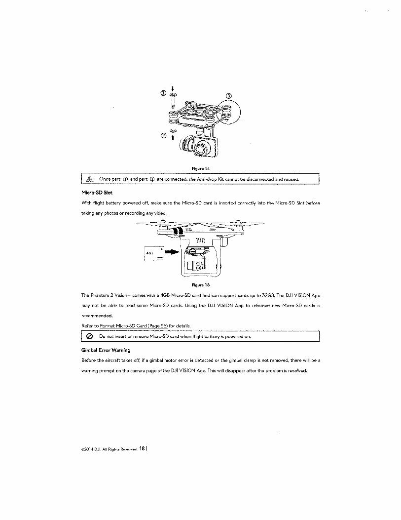
Figurel4
Once part (j) and part (J) are connected, the Anti-drop Kit cannot be disconnected and reused.
Micro-SO Slot
With flight battery powered off, make sure the Micro-SD card is inserted correctly into the Micro-SD Slot before
taking any photos or recording any video.
Figurel5
The Phantom 2 Vision+ comes with a 4GB Micro-SD card and can support cards up to 32GB. The DJI VISION App
may not be able to read some Micro-SD cards. Using the DJI VISION App to reformat new Micro-SD cards is
recommended.
Refer to Format Micro-SD Card (Page 56) for details.
0 Do not insert or remove Micro-SD card when flight battery is powered on.
Gimbal Error Warning
Before the aircraft takes off, if a gimbal motor error is detected or the gimbal clamp is not removed, there will be a
warning prompt on the camera page of the DJI VISION App. This will disappear after the problem is resolved.
©2014 DJI. All Rights Reserved. 18 I
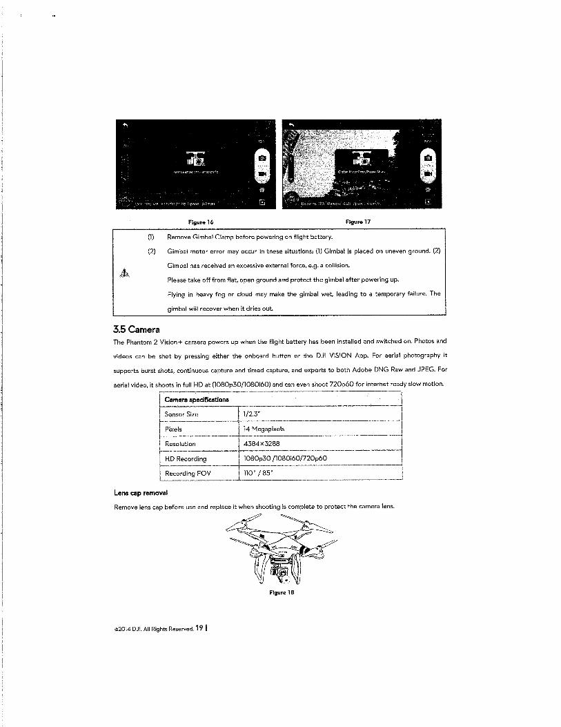
Figure16 Figure 17
(1) Remove Gimbal Clamp before powering on flight battery.
(2) Gimbal motor error may occur in these situations: (1) Gimbal is placed on uneven ground. (2)
Gimbal has received an excessive external force, e.g. a collision.
Please take off from flat, open ground and protect the gimbal after powering up.
Flying in heavy fog or cloud may make the gimbal wet, leading to a temporary failure. The
gimbal will recover when it dries out.
3.5Camera The Phantom 2 Vision+ camera powers up when the flight battery has been installed and switched on. Photos and
videos can be shot by pressing either the onboard button or the DJI VISION App. For aerial photography it
supports burst shots, continuous capture and timed capture, and exports to both Adobe DNG Raw and JPEG. For
aerial video, it shoots in full HD at (1080p30/l080i60) and can even shoot 720p60 for internet ready slow motion. r---- -~
Cemera apecificati~ -~
1/2.3'' J
:::=;,::== ~ ---~ 110" I 85"
Lens cap removal
Remove lens cap before use and replace it when shooting is complete to protect the camera lens.
Figure 18
©2014 DJI. All Rights Reserved. 19 I
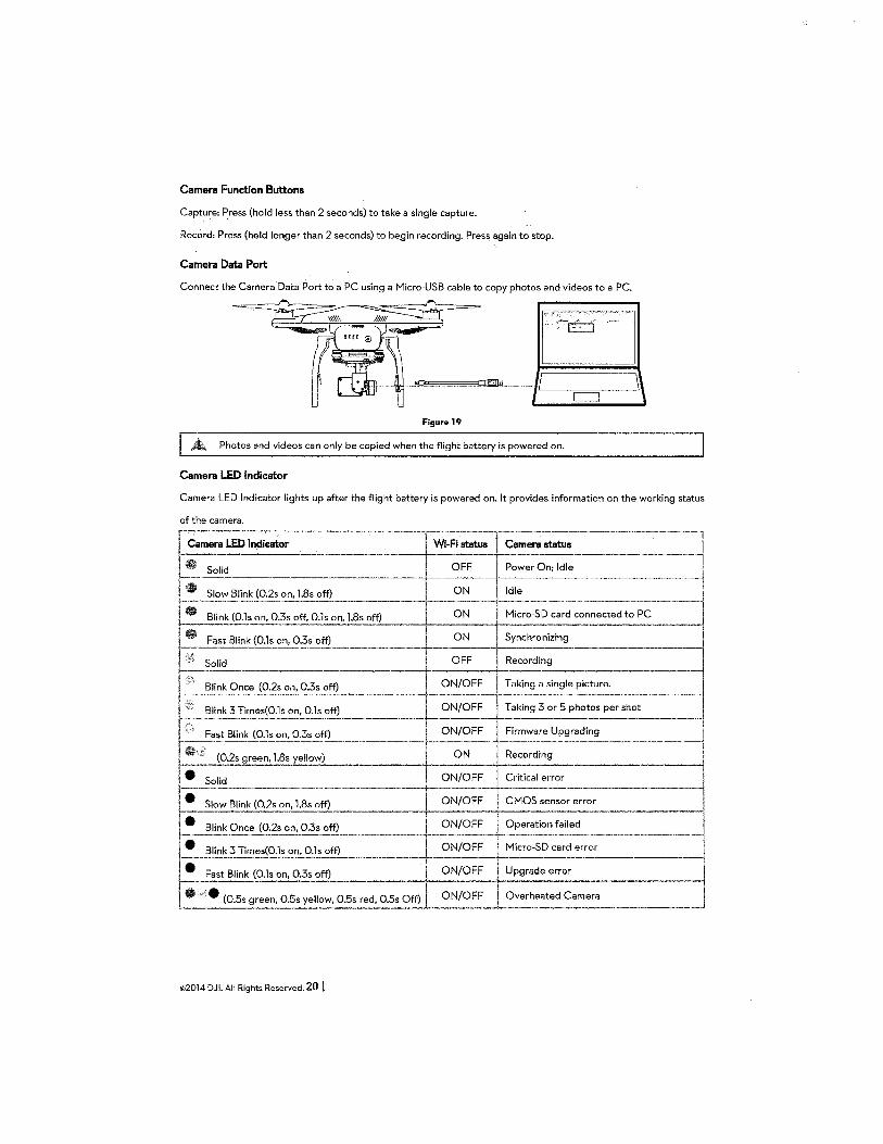
Camera Function Buttons
Capture: Press (hold less than 2 seconds) to take a single capture.
Record: Press (hold longer than 2 seconds) to begin recording. Press again to stop.
Camera Data Port
Connect the Camera Data Port t,; a PC using a Micro-USB cable to copy photos and videos to a PC.
~ L__j
Figure 19
Photos and videos can only be copied when the flight battery is powered on.
Camera LED Indicator
Camera LED Indicator lights up after the flight battery is powered on. It provides information on the working status
©2014 DJI. All Rights Reserved. 20 I
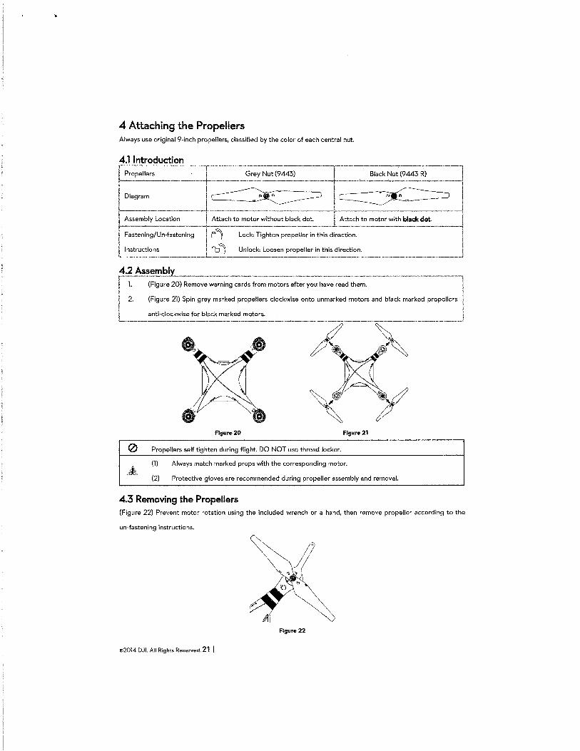
4 Attaching the Propellers Always use original 9-inch propellers, classified by the color of each central nut.
4.1 Introduction ~-- -·-- . . -~---------·--·-~ I Propel_le_rs_...._,------lc- Grey Nut (9443) Black Nut (9443 R) 1
Diagram ~ ~l Asse,;~~-:-cat~~---~- Att~ch to mo~r without black dot. Attach to motor with black dot -i Fastening/Un-fastening f 'l Lock: Tighten propeller in this direction. -~
L~struc~~ns ______ L '0 "') Unlock: Loose~ propeller ~n this directio~: ______________ l ~~~~;i;~~O) Remov:::r-;;;~~ c~~d~·;:-motors after y~u have ~ead ;~;,------------·--·---·] I 2. (Figure 21) Spin grey marked propellers clockwise onto unmarked motors and black marked propellers I I anti-clockwise for black marked motors. I L--------·--------------·-------------.. ----------------·J
A~
Flgure20 Figure 21
0 Propellers self tighten during flight. DO NOT use thread locker.
(l) Always match marked props with the corresponding motor.
(2) Protective gloves are recommended during propeller assembly and removal.
4.3 Removing the Propellers (Figure 22) Prevent motor rotation using the included wrench or a hand, then remove propeller according to the
un-fastening instructions.
Figure 22
©2014 DJI. All Rights Reserved. 21 I
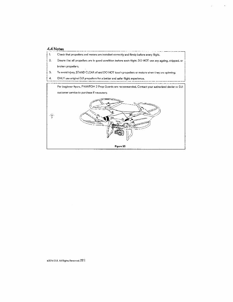
4.4 Notes ~,------------------- ------------------------ -- ------- --------~------~
1 1. Check that propellers and motors are installed correctly and firmly before every flight. I
I 2. Ensure that all propellers are in good condition before each flight. DO NOT use any ageing, chipped, or I ! broken propellers.
1 3. To avoid injury, STAND CLEAR of and DO NOT touch propellers or motors when they are spinning. I L-::.__~~ original DJI pr~pellers for a bett~-~f_::: flight experience. ------- J
For beginner flyers, PHANTOM 2 Prop Guards are recommended. Contact your authorized dealer or DJI
customer service to purchase if necessary.
Figure23
©2014 DJI. All Rights Reserved. 22 I
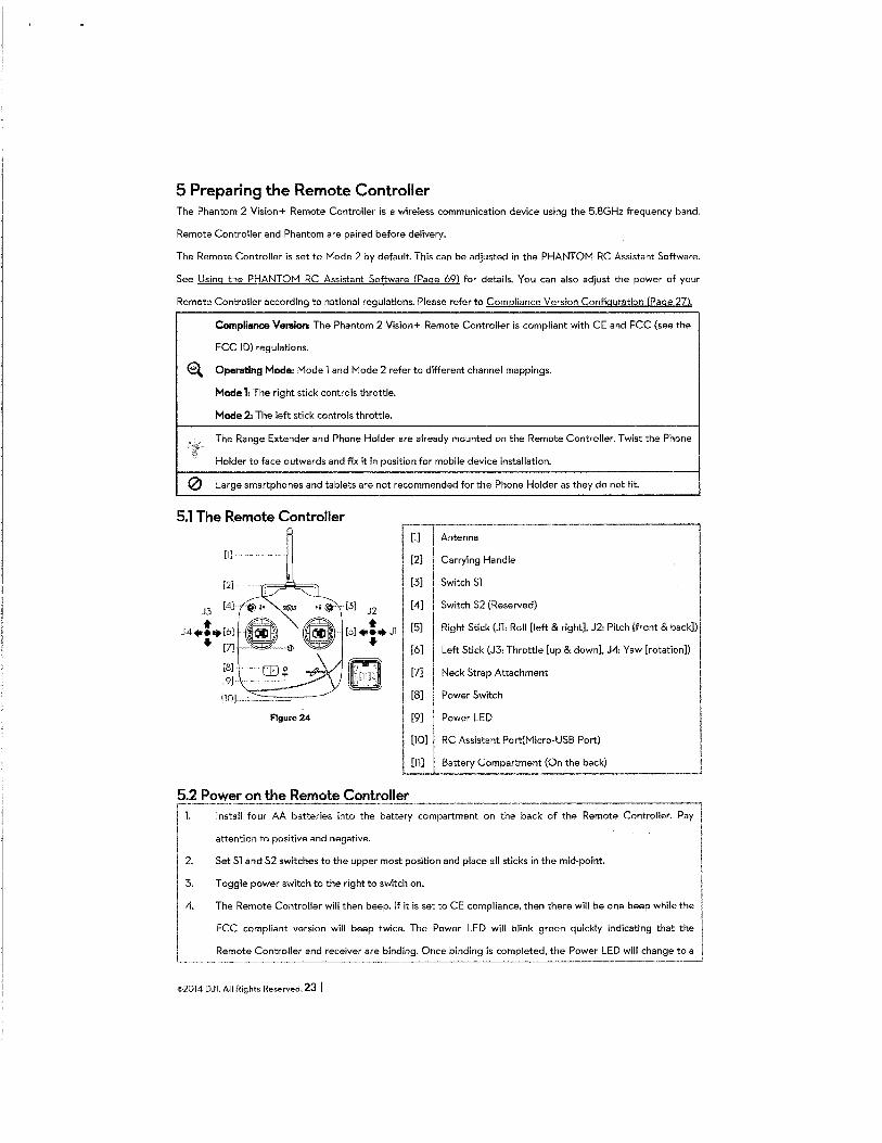
5 Preparing the Remote Controller The Phantom 2 Vision+ Remote Controller is a wireless communication device using the 5.8GHz frequency band.
Remote Controller and Phantom are paired before delivery.
The Remote Controller is set to Mode 2 by default. This can be adjusted in the PHANTOM RC Assistant Software.
See Using the PHANTOM RC Assistant Software (Page 69) for details. You can also adjust the power of your
Remote Controller according to national regulations. Please refer to C omg 1anc e V "on C nfiauration (Pace 27) ers1 0
Compliance Version: The Phantom 2 Vision+ Remote Controller is compliant with CE and FCC (see the
FCC I D) regulations.
a. Operating Mode: Model and Mode 2 refer to different channel mappings.
Mode 1: The right stick controls throttle.
Mode 2: The left stick controls throttle.
The Range Extender and Phone Holder are already mounted on the Remote Controller. Twist the Phone
Holder to face outwards and fix it in position for mobile device installation.
0 Large smartphones and tablets are not recommended for the Phone Holder as they do not fit.
5.1 The Remote Controller
[1]
[2]
J3 [4]
• J4+••[6] ... [7]
[8]
[9]
[10]
[l] Antenna
[2] ~~ Carrying Handle
[3] Switch Sl
[4] Switch 52 (Reserved)
[5] Right Stick (Jl: Roll [left & right], J2: Pitch [front & back])
[6] Left Stick (J3: Throttle [up & down], J4: Yaw [rotation])
[7] Neck Strap Attachment
Power Switch
I
Figure 24
[8]
[9] Power LED
[lO] j RC Assistant Port(Micro-USB Port)
l~l Battery Compartme~ (O_n the back) ___ j 5.2 Power on the Remote Controller r p
J: 14.
I
Install four AA batteries into the battery compartment on the back of the Remote Controller. Pay
attention to positive and negative.
Set Sl and 52 switches to the upper most position and place all sticks in the mid-point.
Toggle power switch to the right to switch on.
The Remote Controller will then beep. If it is set to CE compliance, then there will be one beep while the
FCC compliant version will beep twice. The Power LED will blink green quickly indicating that the
Remote Controller and receiver are binding. Once binding is completed, the Power LED will change to a
©2014 DJI. All Rights Reserved. 23 I
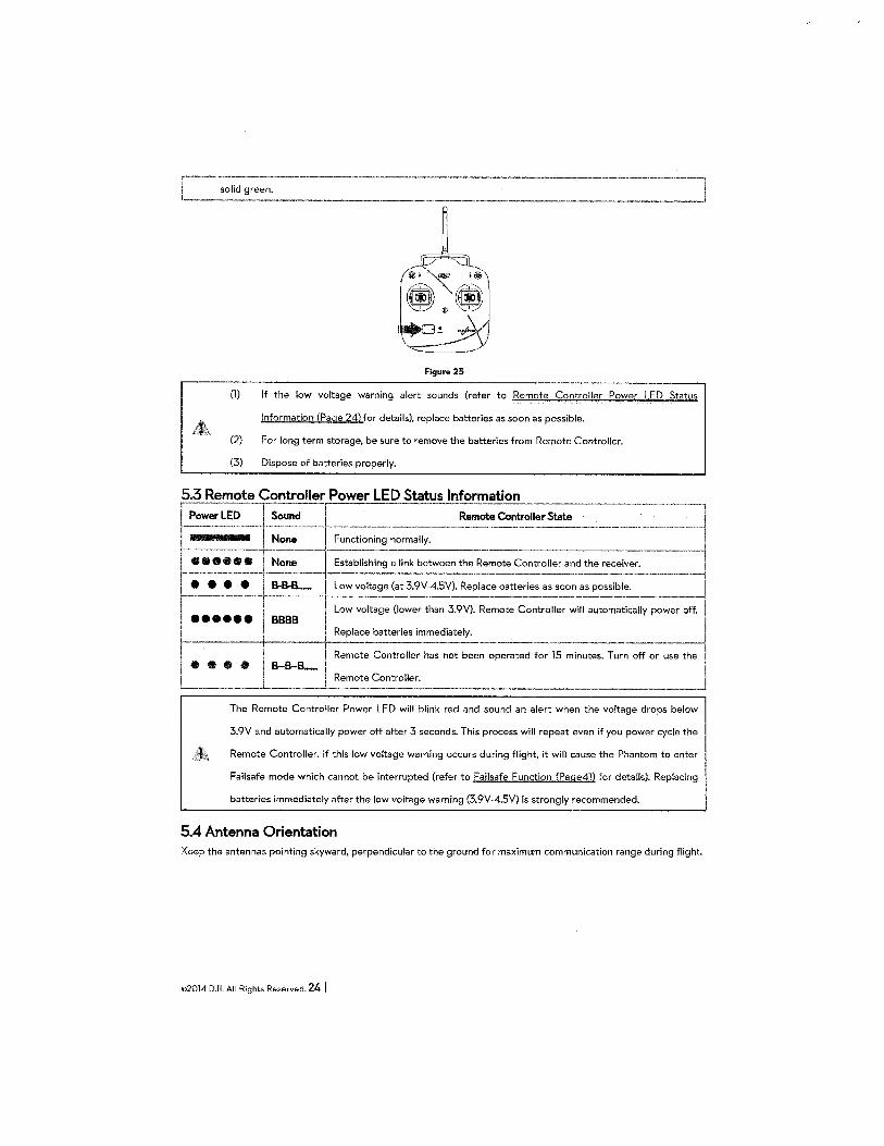
green.
Figure 25
(1) If the low voltage warning alert sounds (refer to Remote Controller Power LED Status
Information (Page 24) tor details), replace batteries as soon as possible.
(2) For long term storage, be sure to remove the batteries from Remote Controller.
(3) Dispose of batteries properly.
5.3 Remote Controller Power LED Status Information
r_.....,~Dn_l;: -- F:,;;:;;;;:-~~-~~_s;::_ ____ ~ r • ; tl •• tl ' No~e--- ~~~;~n~~~tween t~:;::~~ Controller and the receiver~---------1 l t1 t1 t1 t1 ~B.... Low voltage (at 3.9V-4.5V). Replace batteries as soon as possible. -1
II I __ 1
1
Low voltage (lower than 3.9V). Remote Controller will automatically power off.l eeeeee 1 BBBB 'j
1 I ' Replace batteries immediately. ~
~. I ~~ Remote Controller has not been operated for 15 :inut.:.--:;urn off or -:-e the I •••• I 8-B-B- I I I
L__ I ~~==-~troller. ·----- ______ ...J
The Remote Controller Power LED will blink red and sound an alert when the voltage drops below
3.9V and automatically power off after 3 seconds. This process will repeat even if you power cycle the
Remote Controller. If this low voltage warning occurs during flight, it will cause the Phantom to enter
Failsafe mode which cannot be interrupted (refer to Failsafe Function (Page4ll for details). Replacing
batteries immediately after the low voltage warning (3.9V-4.5V) is strongly recommended.
5.4 Antenna Orientation Keep the antennas pointing skyward, perpendicular to the ground for maximum communication range during flight.
©2014 DJI. All Rights Reserved. 24 I
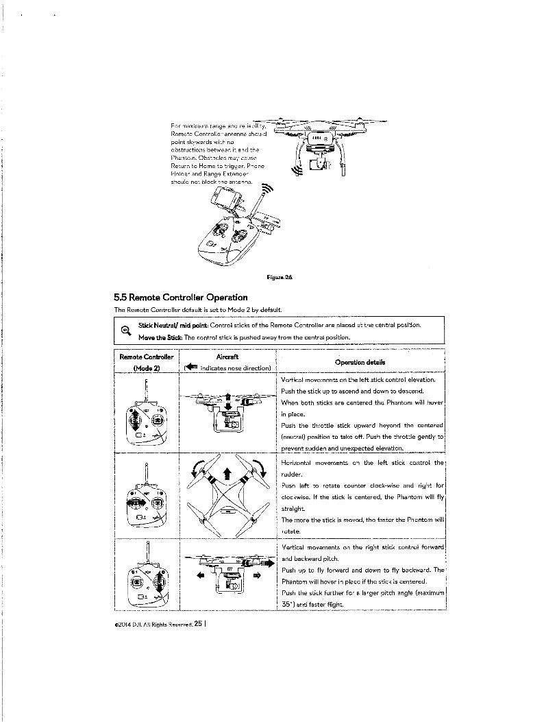
For maximum range and reliability,
Remote Controller· antenna should
point skywards with no
obstructions between it and the Phantom. Obstacles may cause Return to Home to trigger. Phone Holder and Range Extender
should not block the antenna.
5.5 Remote Controller Operation The Remote Controller default is set to Mode 2 by default.
El Stick NeutraV mid point: Control sticks of the Remote Controller are placed at the central position.
Move the Stick: The control stick is pushed away from the central position.
~------:------------~-----------------------,
I Remote Controller I Aircraft ! I
Ft i ...._ l Operation details I
A__!,,',,, (..,.... indicates nose direction) :,,':, Vertical movements on the left stick control elevation.
Push the stick up to ascend and down to descend.
I l When both sticks are centered the Phantom will hover I I ! in place.
l Push the throttle stick upward beyond the centered
(neutral) position to take off. Push the throttle gently to j
·-----.,---,::----___,!-LP~?vent sudden and u~expected elevation_. _____ ..J Horizontal movements on the left stick control the
rudder.
Push left to rotate counter clock-wise and right for
! clockwise. If the stick is centered, the Phantom will fly
I straight. I I J The more the stick is moved, the faster the Phantom will
l lro~~
1
--- -----t-------------·--·---~-+------~--------·-·---·--H-0 _____ _ I Vertical movements on the right stick control forward j
~~~~~=~r£~~~~~.~~ and backward pitch. ! ·11 ... Push up to fly forward and down to fly backward. The I
Phantom will hover in place if the stick is centered. I I Push the stick further for a larger pitch angle (maximum I I I i 35") and fasterflight. I L~-·~-,----~~--·-'---,,~.--·---~--~----~< ___ "_J_"~-~'"~'"'~-.·----.,--,~-~~--,~---~·-·-~-·-·~~,~·~.-·---·---,-~,~J
©2014 DJI. All Rights Reserved. 25 I
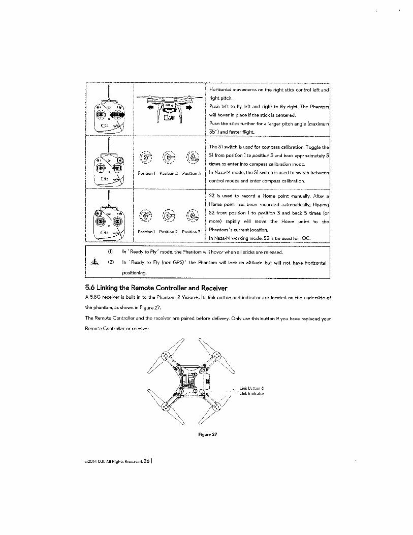
r, -·-----~-·---- ·--~rizonta-;-~~:ements on the right stick controlle~ right pitch. I
!I Push left to fly left and right to fly right. The Phantom I
will hover in place if the stick is centered. I I Push the stick further for a larger pitch angle (maximum r- -r--------------·-r.· 35°) ~d f:sterflight. ----------------1 - The Sl switch is used for compass calibration. Toggle the I I {~~ (~: {(~ I Sl from position 1 to position 3 and back approximately 51
l , '-- '--' '--' times to enter into compass calibration mode. I I i Position 1 Positoon 2 Position 3 j In Naza-M mode, the Sl switch is used to switch between ,
1
-
1 [3~ -&oi ! I control modes and enter compass calibration. .
-----------r------------- ----------rs;-:~::;~o record-: Hom-e-;:int man:,;;;~-~ter a'
I \ Home point has been recorded automatically, flipping
1 · ·~ ,'~ ,~',, !, S2 from position 1 to position 3 and back 5 times (or
lj..;g"",t ~' ~~~~ ', __ , ', __ / -- . more) rapidly will move the Home point to the!
P · · 2 p . . 3 Phantom's current location. :_j ostbon osttton
In Naza-M working mode, S2 is_be ~~~!~~~-
(1) In 'Ready to Fly' mode, the Phantom will hover when all sticks are released.
(2) In 'Ready to Fly {non-GPS)' the Phantom will lock its altitude but will not have horizontal
positioning.
5.6 Linking the Remote Controller and Receiver A 5.8G receiver is built in to the Phantom 2 Vision+. Its link button and indicator are located on the underside of
the phantom, as shown in Figure 27.
The Remote Controller and the receiver are paired before delivery. Only use this button if you have replaced your
Remote Controller or receiver.
©2014 DJL All Rights Reserved. 26 I
Figure 27
Link Button & Link Indicator
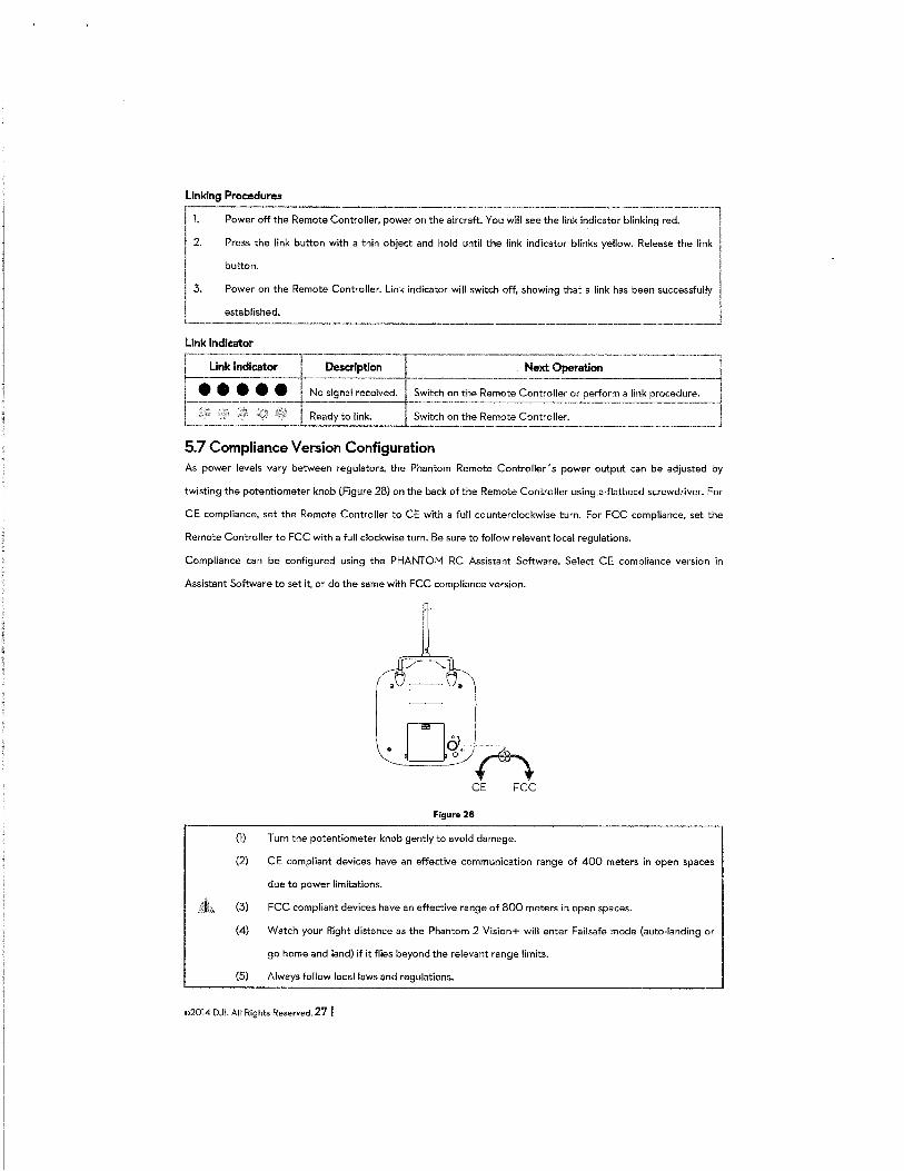
Linking Procedures
Power off the Remote Controller, power on the aircraft. You will see the link indicator blinking red.
Press the link button with a thin object and hold until the link indicator blinks yellow. Release the link
button.
3. Power on the Remote Controller. Link indicator will switch off, showing that a link has been successfully
established.
5.7 Compliance Version Configuration As power levels vary between regulators, the Phantom Remote Controller's power output can be adjusted by
twisting the potentiometer knob (Figure 28) on the back of the Remote Controller using a-flathead screwdriver. For
CE compliance, set the Remote Controller to CE with a full counterclockwise turn. For FCC compliance, set the
Remote Controller to FCC with a full clockwise turn. Be sure to follow relevant local regulations.
Compliance can be configured using the PHANTOM RC Assistant Software. Select CE compliance version in
Assistant Software to set it, or do the same with FCC compliance version.
Figure 28
(1) Turn the potentiometer knob gently to avoid damage.
(2) CE compliant devices have an effective communication range of 400 meters in open spaces
due to power limitations.
(3) FCC compliant devices have an effective range of 800 meters in open spaces.
(4) Watch your flight distance as the Phantom 2 Vision+ will enter Failsafe mode (auto-landing or
go home and land) if it flies beyond the relevant range limits.
(5) Always follow local laws and regulations.
©2014 DJI. All Rights Reserved. 27 I
(l) It is recommended to use a <ll2.4mm flathead screwdriver for adjustments.
(2) There is another potentiometer for reserved use.
©2014 DJI. All Rights Reserved. 28 I
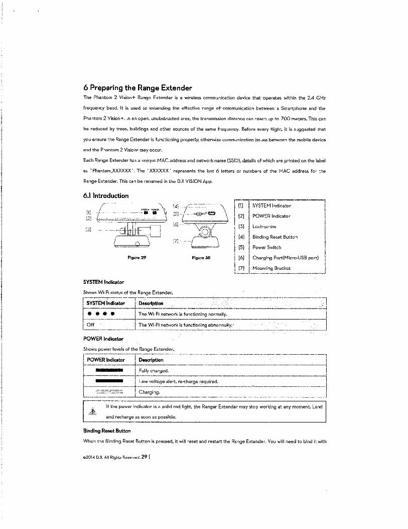
6 Preparing the Range Extender The Phantom 2 Vision+ Range Extender is a wireless communication device that operates within the 2.4 GHz
frequency band .. It "is used to extemling the ·effective range of-communication-between a Smartp-hone and the
Phantom 2 Vision+. In an open, unobstructed area, the transmission distance can reach up to 700 meters. This can
be reduced by trees, buildings and other sources of the same frequency. Before every flight, it is suggested that
you ensure the Range Extender is functioning properly; otherwise communication issues between the mobile device
and the Phantom 2 Vision+ may occur.
Each.Range Extender has a unique MAC-address. and netwo.rk.name.(S.Sll)), details of whlch are printed on the label
as 'Phantom_XXXXXX '. The 'XXXXXX' represents the last 6 letters or numbers of the MAC address for the
Range Extender. This can be renamed in the DJI VISION App.
6.1 Introduction
[1] (2]
(3]
SYSTEM Indicator
Figure 29
Shows Wi-Fi status of the Range Extender.
[5]
(6]
Figure 30
[1] SYSTEM Indicator l [2] POWER Indicator
[3] Lock-screw
[4] Binding Reset Button
[5] Power Switch
[6] Charging Port(Micro-USB port)
[7] Mounting Bracket -----------
SYSTEM Indicator ------------------------·----------l
:':"'W:~~rl< • fuooti=;og oo~lly. I •••• Off The Wi-Fi network is functioning abnormally.--
POWER Indicator
---~+Description Fully charged.
Low voltage alert, re-charge required.
-------
-------------J
~ -----------·-·---------j If the power indicator is a solid red light, the Ranger Extender may stop working at any moment. Land
and recharge as soon as possible.
Binding Reset Button
When the Binding Reset Button is pressed, it will reset and restart the Range Extender. You will need to bind it with
©2014 DJL All Rights Reserved. 29 I
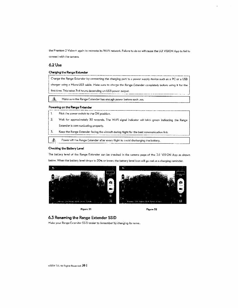
the Phantom 2 Vision+ again to recreate its Wi-Fi network. Failure to do so will cause the DJI VISION App to fail to
connect with the camera.
6.2 Use
Charging the Range Extender
I Charge the Range Extender by connecting the charging ;ort to a power supply device su:·h as a PC or a .USB I I charger using a Micro-USB cable. Make sure to charge the Range Extender completely before using it for the I I first t~me. This takes 3·4 hours ~'!-=~~~ng on ~=~_t:'~~outp~-------"------·--------------J
Make sure the Range Extender has enough power before each use.
Powering on the Range Extender r ,,. I 2.
l::
Flick the power switch to the ON position.
Wait for approximately 30 seconds. The Wi-Fi signal indicator will blink green indicating the
Extender is communicating properly.
Keep the Range Extender facing the aircraft during flight for the best communication link.
Power off the Range Extender after every flight to avoid discharging the battery.
Checking the Battery Level
The battery level of the Range Extender can be checked in the camera page of the DJI VISION App as shown
below. When the battery level drops to 20% or lower, the battery level icon will go red as a charging reminder.
Figure 31 Figure 32
6.3 Renaming the Range Extender SSID 1"1ake your Range 'Extender SSID ·easier·to remember by changing its name ..
©2014 DJI. All Rights Reserved. 30 I
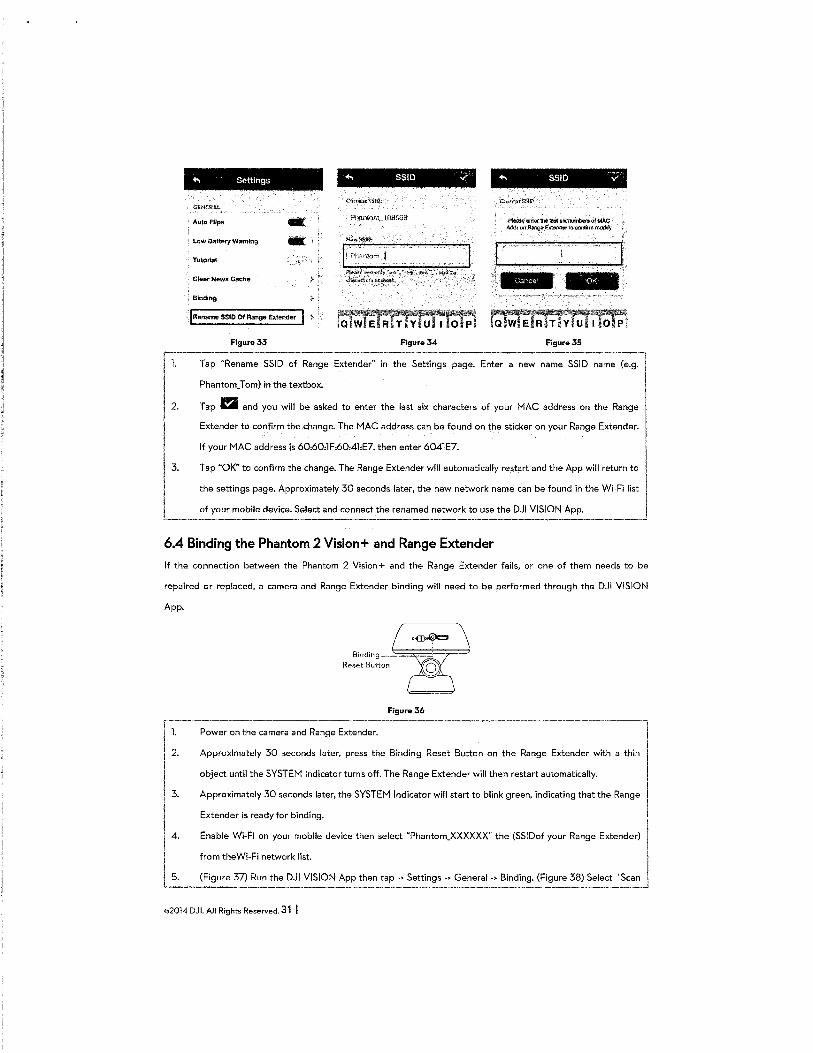
.., Settings
GENERAL
Auto Flips -LOW Battery Warning -Tutorial
Cl&ar News Cache
BincJ;ng ' .'
. J Rename SSID Of Range Exten<fer > "
Figure 33
.., SSID v
lipl,;,,,o,~,j· , ., f'tt!!-lll«': -t%.,.~,:· .. ,_:t"', "0:-11.,;. ,~lte"':'_""~ OO<t ::4 ~*ict-(!~~ -~~i.'
Figure 34
... SSID ..j
............... laota!x-oltMc Adr:;ff orrR~ l?:llt!JrlcllWI:Q.cQn(lfnt tnc:idlly
-· Figure35
r 1. Tap "Rename SSID of Range Extender" in the Settings page. Enter a new name SSID name (e.g.
Phantom_T om) in the textbox.
2. Tap 1!1 and you will be asked to enter the last six characters of your MAC address on the Range
Extender to confirm the change. The MAC address can be found on the sticker on your Range Extender.
II
If your MAC address is 60:60:1F:60:4l:E7, then enter 6041E7.
13. Tap "OK" to confirm the change. The Range Extender will automatically restart and the App will return to
e settings page. Approximately 30 seconds later, the new network name can be found in the Wi-Fi list
f your mobile device. Select and connect the renamed network to use the DJI VISION App. - I
6.4 Binding the Phantom 2 Vision+ and Range Extender
If the connection between the Phantom 2 Vision+ and the Range Extender fails, or one of them needs to be
repaired or replaced, a camera and Range Extender binding will need to be performed through the DJI VISION
App.
Figure36
r~:--·;::-:-:n~he c::~a and R~nge Extend:-----·---·----------------·-------~
I 2. Approximately 30 seconds later, press the Binding Reset Button on the Range Extender with a thin I object until the SYSTEM Indicator turns off. The Range Extender will then restart automatically.
3. Approximately 30 seconds later, the SYSTEM Indicator will start to blink green, indicating that the Range
I Extender is ready for binding.
l!~' 4. -Ena-ble Wi-Fi on your mobile device then select "Phantom_XXXXXX" the (SSIDof your Range Extender)
from theWi-Fi network list.
5. (Figure 37) Run the DJI VISION App then tap -> Settings -> General -> Binding. (Figure 38) Select 'Scan ·--~-·---·-----·
©2014 DJI. All Rights Reserved. 31 I
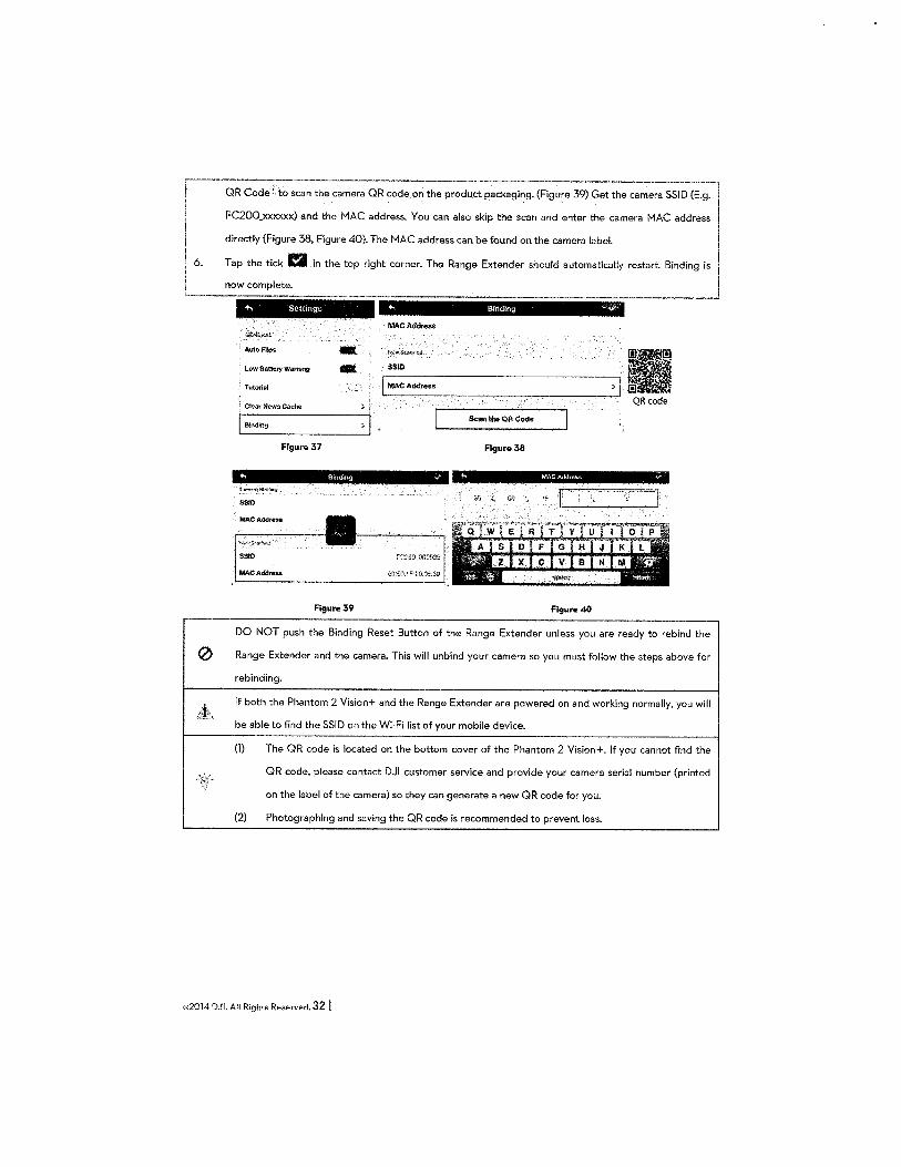
~--· ·-----·----·-·----~-----------, l OR Code' to scan the camera OR code on the product packaging. (Figure 39) Get the camera SSID {E.g. I
I. FC200_xxxxxx) and the MAC address. You can also skip the scan and enter the camera MAC address I
directly (Figure 38, Figure 40). The MAC address can be found on the camera label.
~6~ :: :m::,~ lo ;he ro, 1'h' ~1001. Tho Roogo ''""'" moold ·-•""'" ~rn~.Biodi:•J +. Settings ~ Bmding -v
MAC Address
Auto fUp!t
' l.ow Battery Warning SSID
Tutorial I MACAddress
; Ctear News Cache } '
I Binding Scan the OR Code
Figure> 37 Figure>38
""' Bmdlng if
SSIO
SSIO
MAC Address
Figura39 Flgur" 40
DO NOT push the Binding Reset Button of the Range Extender unless you are ready to rebind the
0 Range Extender and the camera. This will unbind your camera so you must follow the steps above for
rebinding.
If both the Phantom 2 Vision+ and the Range Extender are powered on and working normally, you will
be able to find the SSID on the Wi-Fi list of your mobile device.
(1) The OR code is located on the bottom cover of the Phantom 2 Vision+. If you cannot find the
OR code, please contact DJI customer service and provide your camera serial number (printed
on the label of the camera) so they can generate a new OR code for you.
{2) Photographing and saving the OR code is recommended to prevent loss.
©2014 DJI. All Rights Reserved. 32 I
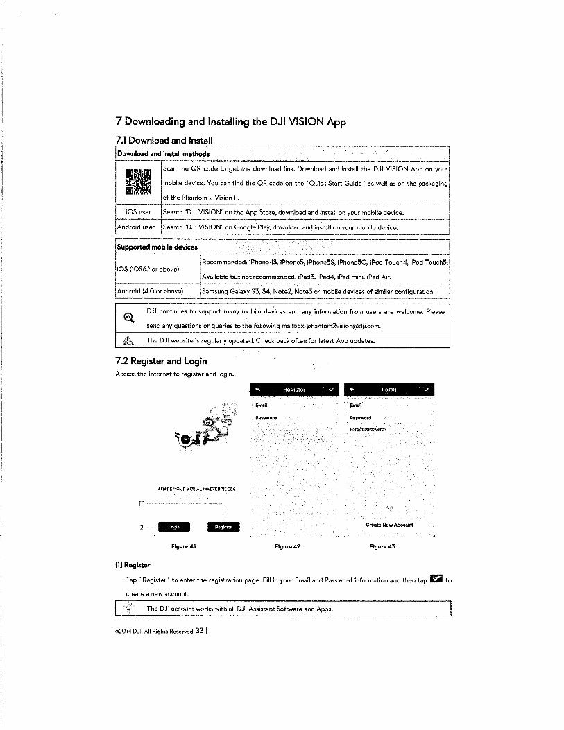
7 Downloading and Installing the DJI VISION App
7.1 Download and Install Download and inmll methc.=o=d::s:.___._____ . -----~
--~n the QR code to get the download link. Download and install the DJI VISION App on you~ ~ I mobile device. You can find the QR code on the 'Quick Start Guide' as well as on the packaging I
1------·-jof the Phantom 2 Vision+. . ---- ·
iOS user __ ! search "DJI VISION" on the App Store, download and install on your -~obile device. j ~ndroid u:=~~~~N" ~n Google Play, download and install on your mobile device. _j
Supported mobile devices - - - - I ----------~~ecommended: iPhone4S, iPhoneS, iPhoneSS, iPho~eSC, iPod Touch4, iPod-;ouchS~~ iOS (i0S6.1 or above) ----------- Available but not recommended: iPad3, iPad4, iPad mini, iPad Air. J
Android (4.0 or above) ·-··JS.~m~un~ Galaxy 53, 54, Note2, Note3 o~ mobile devices ~f similar config~ration. J
DJI continues to support many mobile devices and any information from users are welcome. Please
send any questions or queries to the foUowing mailbox: [email protected].
The DJI website is regularly updated. Check back often for latest App updates.
7.2 Register and Login Access the Internet to register and login.
+, Register v +, Logtn v
Email • Email
Paaword Paw-sword
SHARE YOUR AERIAl MASTERPIECES
[1]
[2] .. ·*!iii!!* *Mb* Create New Account
Flgure41 Figure42 Figure43
[1] Register
Tap' Register' to enter the registration page. Fill in your Email and Password information and then tap F..i to
create a new account.
The DJI account works with all DJI Assistant Software and Apps.
©2014 DJI. All Rights Reserved. 33 I
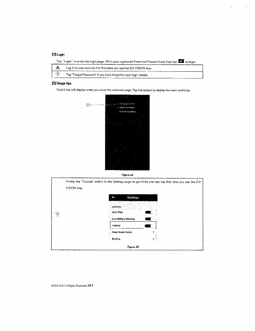
[2] Login
Tap 'Login' to enter the login page. Fill in your registered Email and Password and then tap a to login.
Log in to your account the first time you use the DJI VISION App.
Tap "Forgot Password" if you have forgotten your login details.
[3] Usage tips
Useful tips will display when you enter the welcome page. Tap the screen to display the next useful tip.
[3]- ..
Figure 44
Enable the "Tutorial" switch in the Settings page to get hints and tips the first time you use the DJI
VISION App.
+. Settings
..-;ENJ;RA~
' Auto Flips -' Low Battery Warning .•
IL-T_u_to_n_·a_l ------ - ]
Clear News Cache
; Binding
Figure 45
©2014 DJL All Rights Reserved. 34 I
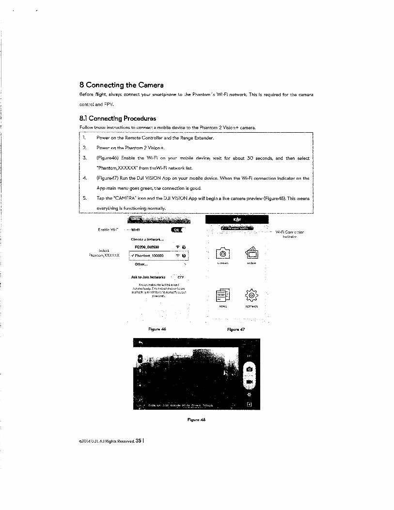
8 Connecting the Camera Before flight, always connect your smartphone to the Phantom's Wi-Fi network. This is required for the camera
control and FPV.
8.1 Connecting Procedures Follow these instructions to connect a mobile device to the Phantom 2 Vision+ camera.
1. Power on the Remote Controller and the Range Extender.
2. Power on the Phantom 2 Vision+.
3. (Figure46) Enable the Wi-Fi on your mobile device; wait for about 30 seconds, and then select
"Phantom_XXXXXX" from theWi-Fi network list.
4. (Figure47) Run the DJI VISION App on your mobile device. When the Wi-Fi connection indicator on the
App main menu goes green, the connection is good.
5. Tap the "CAMERA" icon and the DJI VISION App will begin a live camera preview (Figure48). This means
everything is functioning normally.
Enable 'vVi-Fi
Select Phantorn_XXXXXX
· Wi-Fi
Choose a Network ...
j -1 PhantonU00020
Other ...
Ask to Join Networks <IFf
Knv'l'.-n r.ett·oo•ks vtih be k;io:ed 3utmn8lit:ally. ff 110 t;nDwn ~1-,.vmk.s r:we
:::.·;aJlab~. y•Ju \\:f!,:~~:~!~_manual~v :;~::<...ct
NEWS SETrlNG'J.
Figure 46 Figure 47
Figur& 48
©2014 DJI. All Rights Reserved. 35 I
Wi-Fi Connection 1ndicatcr
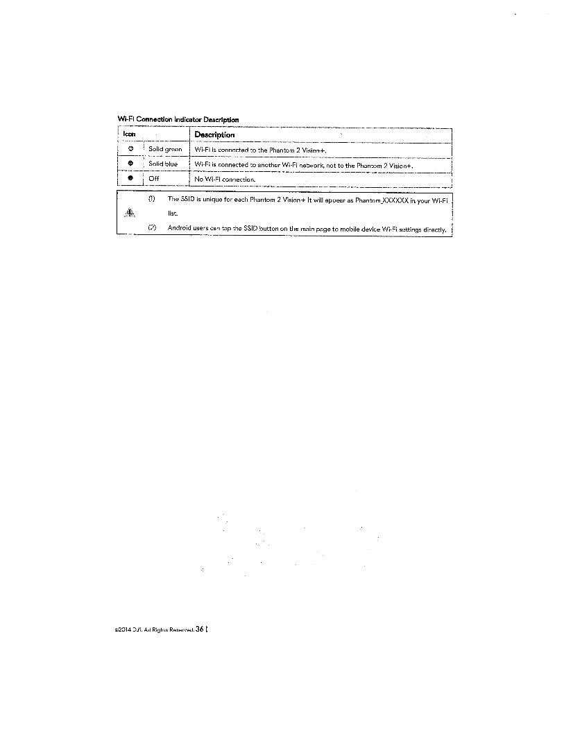
Wi-Fi Connection Indicator Description
Icon Description
green Wi-Fi is connected to the Phantom 2 Vision+.
blue Wi-Fi is connected to another Wi-Fi network, not to th.e Phantom 2 Vision+.
No Wi-Fi connection.
(1) The SSID is unique for each Phantom 2 Vision+ It will appear as Phantom_XXXXXX in your Wi-Fi
list.
(2) Android users can tap the SSID button on the main page to mobile device Wi-Fi settings directly.
©2014 DJI. All Rights Reserved. 36 I
Flight Once pre-flight preparation is complete, it is recommended to carry out the tasks in the Phantom Pilot Training
Guide to prepare .for more complex flight maneuvers and-learn to fly safely. Ensure that all flights are carried out in
a suitable location.
Flight Environment Requirements
r~:·--o::~ ~se t;: aircraf~-in ~evere weather conditions. ~hes: include wind s~:ed exceeding- catego;;:;··l,
1 snow, ram and smog. l ! ' 2 Fly in open fields as high buildings or steel structures may affect the accuracy of the onboard compass. \
3. Keep the Phantom away from obstacles, crowds, high voltage power lines, trees or bodies of water when l . in flight. ,ill
4. Reduce the chance of electromagnetic interference by not flying in areas with high levels of
electromagnetism, including base stations or radio transmission towers. J I 5. The Phantom cannot operate within the polar areas.
L~ Do not fly the ai~=raft w~hin no-fly zones specified by local laws and regulations. i
Preflight Checklist
0· Remote_C_o_n-tr_o_ll_e-r,_s_m_a_r_t_b_a-tt_e.ry, Range Extender and smartphone are fully charged. --·---, I I
!2· 3.
4.
5.
,,6. 7.
Is.
~~
Propellers are mounted correctly.
Gimbal clamp has been removed.
Damping absorbers are in good condition, not broken or worn.
Anti-drop kits have been mounted correctly.
Camera lens cap has been removed.
fvlicro-SD card has been inserted if necessary.
Gimbal is functioning as normal.
Motors can start and are functioning as normal.
DJI VISION App can connect to the camera. -------------
©2014 DJI. All Rights Reserved. 37 I
I l I
I ________ j
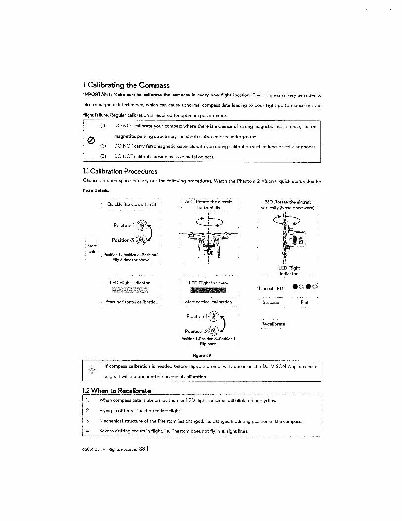
1 Calibrating the Compass IMPORT ANT: M11ke sure to calibrete the c:ompess in every new flight location. The compass is very sensitive to
electromagnetic interference, which can cause abnormal compass data leading to poor flight performance or even
flight failure. Regular calibration is required for optimum performance.
(1) DO NOT calibrate your compass where there is a chance of strong magnetic interference, such as
magnetite. parking structures, and steel reinforcements underground. 0 (2) DO NOT carry ferromagnetic materials with you during calibration such as keys or cellular phones.
(3) DO NOT calibrate beside massive metal objects.
1.1 Calibration Procedures Choose an open space to carry out the following procedures. Watch the Phantom 2 Vision+ quick start video for
more details.
, Start cali
Quickly flip the switch Sl
Position-] :(~) ~~ ... t
~ ...
Position-3 {:~ ~ ,-: .......
Position-1-~Position-3->Position-1 Flip 5 times or above
LED Flight Indicator
Start horizontal calibratic ..
360° Rotate the aircraft horizontally_
I
~~ I
~1llr~' . ":$ I '
LED Flight Indicator
Start vertical calibration
Position-]:~:) Position-3 ~'~ ..... _ ..
Position-1->Position-3-~Position-1
Flip once
Figure 49
360°Rotate the aircraft vertically (Nose downward)
LED Flight Indicator
Normal LED • • Succeed Fnil
Re-calibrate
If compass calibration is needed before flight, a prompt will appear on the DJI VI SON App 's camera
page. It will disappear after successful calibration.
1.2 When to Recalibrate
~,-2
1.. When compass data is abnormal, the rear LED flight indicator will blink red and yellow. -~~~ l Flying in different location to last flight.
I 3. Mechanical structure of the Phantom has changed, i.e. changed mounting position of the compass. I ~ I L~-- Se:':~ dri~ing occu~s in fl~~ht, i.e.~hantom does not fi~~~~~~-~-------------·---J
©2014 DJI. All Rights Reserved. 38 I
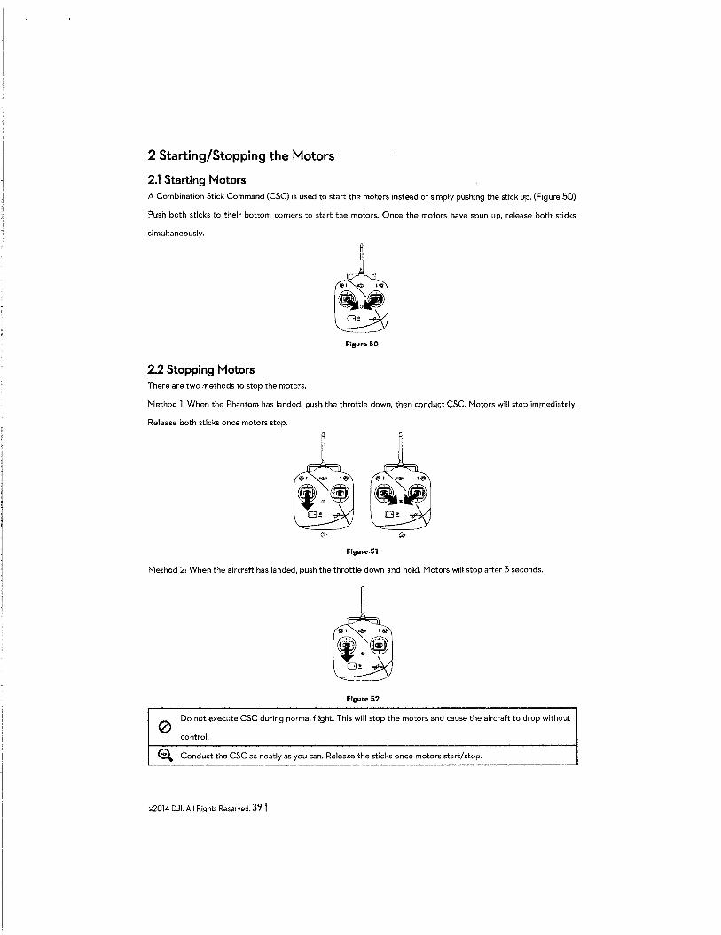
2 Starting/Stopping the Motors
2.1 Starting Motors A Combination Stick Command (CSC) is used to start the motors instead of simply pushing the stick up. (Figure 50)
Push both sticks to their bottom corners to start the motors. Once the motors have spun up, release both sticks
simultaneously.
Figure 50
2.2 Stopping Motors There are two methods to stop the motors.
i'1ethod 1: When the Phantom has landed, push the throttle down, then conduct CSC. Jv1otors will stop immediately.
Release both sticks once motors stop.
Figure.51
Jv1ethod 2: When the aircraft has landed, push the throttle down and hold. Jv1otors will stop after 3 seconds.
Figure 52
0 Do not execute CSC during normal flight. This will stop the motors and cause the aircraft to drop without
control.
~ Conduct the CSC as neatly as you can. Release the sticks once motors start/stop.
©2014 DJI. All Rights Reserved. 39 I
3 Flight Test
3.1 Take off/Landing Procedures ~--P-;ace the Phantom 2 Vision+ on open flat ground with battery indicators facing towards yo~. l
2.
3.
4.
5.
6.
7.
8.
::::h::h:J:::~:~:~: ::: ~::~.':"::: ::~~:~:::~;::.~:·:~",, .. ;~pogo. I Wait until the Rear LED Flight Indicator blinks green. This means it has initialized and is Ready to Fly. If it I flashes yellow, it is in Ready to Fly (non-GPS) mode and will require more careful flight. Execute the CSC
command to start motors.
Push the throttle up slowly to take off. Refer to Remote Controller Operation (Page 25) for more details.
Shoot photos and videos using the DJI VISION App. Refer to DJI VISION App Usage (Page 48) for more
details.
To land, hover over a level surface and gently pull down on the throttle gently to descend.
After landing, execute the CSC command or hold the throttle at its lowest position for 3 seconds or more
until the motors stop.
Turn off the smart battery, Range Extender and Remote Controller. J (1) When the Rear LED Flight Indicator blinks yellow rapidly during flight, the aircraft has entered
Failsafe mode. Refer to Failsafe Function (Page 41l for details.
(2) A low battery level warning is indicated by the Rear LED Flight Indicator blinking red slowly or
rapidly during flight. Refer to the Low Battery Level Warning Function (Page) for details.
(3) View tutorials about flight for more flight information: www.dji.com/phantom2visionplus/training.
3.2 Vid~~est~~ns and .Ties ~ Work through the check list before each flight.
I 2. Set the gimbal working mode to Stabilized.
3. Aim to shoot when flying in Ready to Fly only.
4. Always fly in good weather, such as sunny or windless days.
5. Change camera settings to suit you. These include FOV, photo format and exposure compensation.
6. Take flight tests to establish flight routes and scenes.
7. Push the sticks gently to make aircraft movements stable and smooth.
©2014 DJI. All Rights Reserved. 40 I
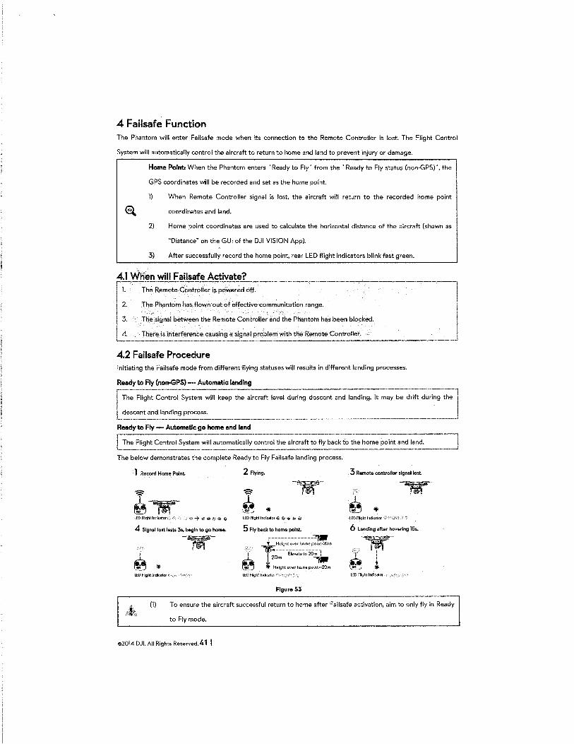
4 Failsafe Function The Phantom will enter Failsafe mode when its connection to the Remote Controller is lost. The Flight Control
System will automatically control the aircraft to return to home and land to prevent injury or damage.
Home Point: When the Phantom enters 'Ready to Fly' from the 'Ready to Fly status (non-GPS) ', the
GPS coordinates will be recorded and set as the home point.
1) When Remote Controller signal is lost, the aircraft will return to the recorded home point
coordinates and land.
2) Home point coordinates are used to calculate the horizontal distance of the aircraft (shown as
"Distance" on the GUI of the DJI VISION App).
3) After successfully record the home point, rear LED flight indicators blink fast green.
4.1 When will Failsafe Activate? 1. The Remote Controller is powered <iff. ~ 2. The Phantom has flown·out of effective communication range. '
3. The signal between the Remote Controller and the Phantom has been blocked. 1
1
4. There is interference causing a signal problem with the Remote Controller. j
--------------------------------4.2 Failsafe Procedure Initiating the Failsafe mode from different flying statuses will results in different landing processes.
Ready to Fly (non-GPS) -··Automatic landing
Flight Control System will keep the aircraft level during descent and landing. It may be drift during the
and landing process.
Ready to Fly- Automatic go home end land
lrhe Flight Control System will automatically control the aircraft to fly back to the home point and land.
The below demonstrates the complete Ready to Fly Failsafe landing process.
1 Record Home Point. 2 Flying. 3 Remote controller signellost.
lEDFIIghtlndicatoro) ,. LED Flight Indk:ator ·.{i.· $~ ~ ~ ~' LED Flight Indicator
4 Signal lost l .. ts 3s. begin to go home. 6 Lending after hovering 153.
~
LED FRglrt lndkator ;_· ·
Figure 53
(1) To ensure the aircraft successful return to home after Failsafe activation, aim to only fly in Ready
to Fly mode.
©2014 DJI. All Rights Reserved. 41 I
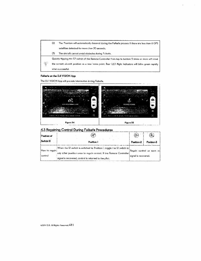
(2) The Phantom will automatically descend during the Failsafe process if there are less than 6 GPS
satellites detected for more than 20 seconds.
(3) The aircraft cannot avoid obstacles during Failsafe.
Quickly flipping the S2 switch of the Remote Controller from top to bottom 5 times or more will reset
the current aircraft position as a new home point. Rear LED flight indicators will blink green rapidly
when successful.
Failsafe on the DJI VISION App
The DJI VISION App will provide information during Failsafe.
Figure 54 Figura 55
~ini1ng Contt:_ol During Fails~!~ Procedur.co.es"---·
I::M~~l ,;~, Regain control as soon as
~l' How to regain !'When the Sl switch is switched to Position-1, toggle the Sl switch to
any other position once to regain control. If the Remote Controller control j signal is recovered.
1 signal is recovered, control is returned to the pilot. ____ __J_________________ "-----·
©2014 DJI. All Rights Reserved. 42 I
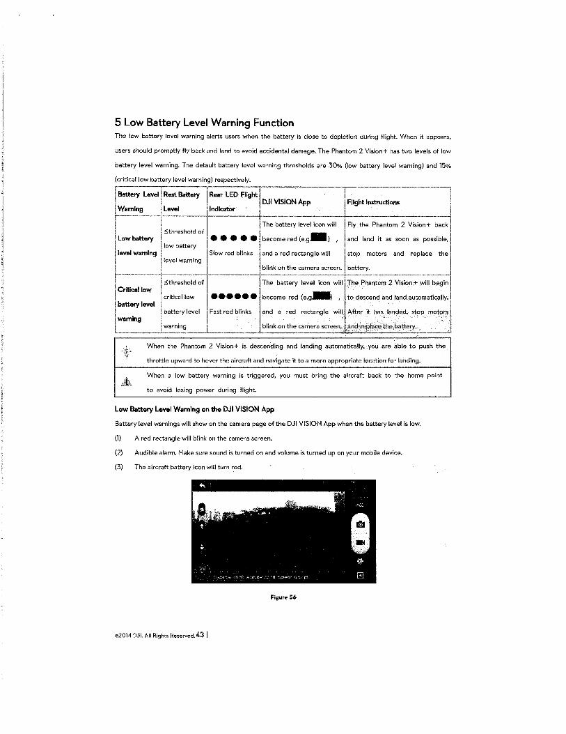
5 Low Battery Level Warning Function The low battery level warning alerts users when the battery is close to depletion during flight. When it appears,
users should promptly fly back and land to avoid accidental damage. The Phantom 2 Vision+ has two levels of low
battery level warning. The default battery level warning thresholds are 30% (low battery level warning) and 15%
(critical low battery level warning) respectively.
ls~ttery Levell Rest Battery·-r,-Rea_r_l_E.~ -D--RI·-g-ht,·-------·---- ,.--·-----------------.,~
~- DJI VISION App Flight Instructions ' ~mlng l Level I Indicator ~~
l ·-----~--r. ~he battery level icon will Fly the Phantom 2 Vision+ back 'j i S.threshold of - i Low,_, I e e e e -~ b~om""<l (o.g ) ' ""' l•od '""""" •• I"'~••· I
I low battery I ''"" -"• Slow ;od bi;•k• ood "'"" ;octoogO will '"'P mo<oo ood ••pO<o "'"I
level warning ------- 4' blink on the camera screen. battery.
I S.threshold I The battery level icon will The Phantom 2 Vision+ will begin j
I Critical low I critical low J ••••• e become red (e.g_, , to descend and land automatically.!
battery level warning I battery level I Fast red blinks I and a red rectangle. w. ill, After it has land~d; stop motors
warning i · blink on the camera screen., .~r<:~r:~pli3C!il,th'i' battery.
When the Phantom 2 Vision+ is descending and landing automatically,. you are able to push the.
throttle upward to hover the aircraft and navigate it to a more appropriate location for landing.
When a low battery warning is triggered, you must bring the aircraft back to the home point
to avoid losing power during flight.
Low Battery Level Warning on the DJI VISION App
Battery level warnings will show on the camera page of the DJI VISION App when the battery level is low.
(1) A red rectangle will blink on the camera screen.
(2) Audible alarm. Make sure sound is turned on and volume is turned up on your mobile device.
(3) The aircraft battery icon will turn red.
Figur<> 56
©2014 DJI. All Rights Reserved. 43 I
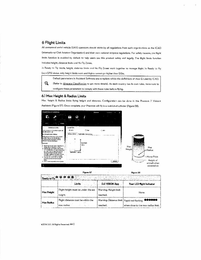
6 Flight Limits All unmanned aerial vehicle (UAV) operators should abide by all regulations from such organizations as the ICAO
(International Civil Aviation Organization) and their own national airspace regulations. For safety reasons, the flight
limits function is enabled by default to help users use this product safely and legally. The flight limits function
includes height, distance limits and No Fly Zones.
In Ready to Fly mode, height, distance limits and No Fly Zones work together to manage flight. In Ready to Fly
(non-GPS} status, only height limits work and flights cannot go higher than 120m.
Default parameters in Assistant Software are compliant within the definitions of class G ruled by ICAO.
€'4 (Refer to Airspace Classification to get more details). As each country has its own rules, make sure to
configure these parameters to comply with these rules before flying.
6.1 Max Height & Radius Limits Max Height & Radius limits flying height and distance. Configuration can be done in the Phantom 2 Vision+
Assistant (Figure 57). Once complete, your Phantom will fly in a restricted cylinder (Figure 58).
PHANTOM 2 VISION+ -Ph~mom ,.. , 1 .. - X
ro..!' a® i I "• I ,,1
·)
':'! r: ' ' i1m1l'ii
Distance Limit!~
Dl~lance Umtts Include hla>::Mighl limit andMallradJuo:lmlrt.
:~ =~~~~~\~~:;:~~v~:U~~diU$ :2. Onii}Tb!OIIIeanGRuddereommancls
aooa'fallab!effthealrcrattrus!'le!!.oulof lheHmits,tmdilv/11\llyblltll\l:lwards Home polntaU1omattcaiiY. Remote controllerregemsellconlrolsoncethe aftuaftle¥11thlnthegrsl!nalrspQca.
J. The Failsafe and !he GroundSta~on rur.ctlor~sarenotal'feeteabyTUgl'tt
limits. ~ Refertousermanua5formoredetalls.
l.<W~hiJnt.;
®llleler C;Feet
-_ I·"""'~ 500m
--~ i.laliAadli.l§ 1500!'1'1
Figure 57 ["~---.. -. ----.. -~-.. ,--. -'~~·
(•Mile
powered on
Figure 58 ---.--.-.-. -.----1
I 1..1!.-~~-Fty. .. . , . .;.;__,:----r--- . .·
L. ________ 1~.-· ==~~==~__:·L=im=its~~-~---..:...-----~---..,-~~D~J~I~;...;-_:::.:.SI:ON=-~Aw,_._· -~--R~r LED flight ind~cat_or __ ll I I Flight height must be under the set Warning: Height lir'nit 1 Max Height I None. I L 1 height. reached. .
~------"1~ Flig_h_t_d-is-t-an_c_e_m_u_s_t_b_e_w-.-,t-hi_n_t_h_e--+W~a-r-n-in_g_:_D~i-sta,nce limit Rapid red flashing --~ 1 Max Radius J I i m:: rad!us. reach~~-- ! when close t~the max r_:~ius ~~
©2014 DJI. All Rights Reserved. 44 I
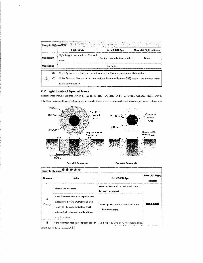
{1) If you fly out of the limit, you can still control the Phantom, but cannot fly it further.
{2) If the Phantom flies out of the max radius in Ready to Fly {non-GPS) mode, it will fly back within
range automatically.
6.2 Flight Limits of Special Areas Special areas include airports worldwide. All special areas are listed on the DJI official website. Please refer to
http://www.dii.com/fly-safe/category-mc for details. These areas have been divided into category A and category B.
BlOOm·
Figure 59: Category A Figure 60: Category B
Center of Special
Area
Airspace: A,C,D Boundary: fi., ,1;,
~::y to Fly ~ocl~. • . . . I .---------r----. ------.~ I I l Rear LED Flight I
~:-~-------~im~-----·· · DJI VISION App +--~~cator -----1 I I
Warning: You are in a restricted zone. j'
Motors will not start. c Take off prohibited !
I If the Phant~m fl~es int~-a special area I I I A ' I I
I in Ready to Fly {non·GPS) mode and 1
1"
I
! Orange I Warning: You are in a restricted zone. ! ...... , Ready to Fly mode activates, it will j
I Now descending. 1 I automatically descend and land then
I I stop its motors. I I B _t the Ph_:_ntom ~ies into a s~ecial area in Warning: You Are In A Restricted Zone,i
©2014 DJI. All Rights Reserved. 45 I J
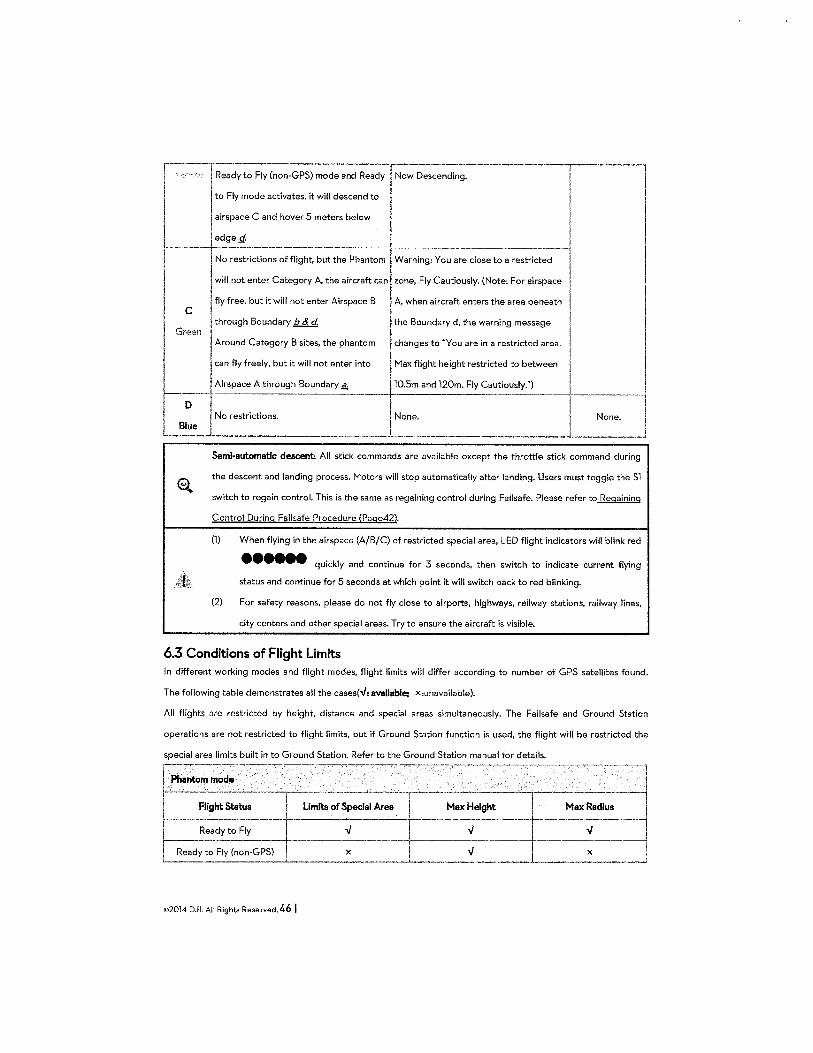
~---, •
1
! Ready to ~y (non-GPS) mode a:; Ready ~escend~;--------~ I ! ,
J-to Fly mode activates, it will descend to I I
airspace C and hover 5 meters below I I ~------ ~dg-:_~------------------1--------------,-------~ I No restrictions of flight, but the Phantom I Warning: You are close to a restricted 1
' I
I will not enter Category A. the aircraft can zone, Fly Cautiously. (Note: For airspace I
I C fly free, but it will not enter Airspace B A, when aircraft enters the area beneath I
through Boundary b & d the Boundary d, the warning message I '~MI I
~ Around Category B sites, the phantom changes to "You are in a restricted area. I
, can fly freely, but it will not enter into Max flight height restricted to between 1 ,--t Ai"P"" A <h<0'9h '""'"'' ~ .] 10.5m and 120m. Fly Cautiously.") ! I ! No restrictions. None. I None.
l-L _ L
--j
_j Semi-automatic descent; All stick commands are available except the throttle stick command during
the descent and landing process. Motors will stop automatically after landing. Users must toggle the Sl
switch to regain control. This is the same as regaining control during Failsafe. Please refer to Regaining
Control During Failsafe Procedure (Page42).
(1) When flying in the airspace (A/B/C) of restricted special area, LED flight indicators will blink red
•••••• quickly and continue for 3 seconds, then switch to indicate current flying
status and continue for 5 seconds at which point it will switch back to red blinking.
(2) For safety reasons, please do not fly close to airports, highways, railway stations, railway lines,
city centers and other special areas. Try to ensure the aircraft is visible.
6.3 Conditions of Flight Limits In different working modes and flight modes, flight limits will differ according to number of GPS satellites found.
The following table demonstrates all the cases(-./: avaOable; X:unavailable).
All flights are restricted by height, distance and special areas simultaneously. The Failsafe and Ground Station
operations are not restricted to flight limits, but if Ground Station function is used, the flight will be restricted the
special area limits built in to Ground Station. Refer to the Ground Station manual for details.
~~ -f~-~~~: I -~~~~~-l L_ Rea~-t~~~ (non-GPS) __l_ ____ x __ __j _____ "_ ___ _j_ ______ x ______ _j
©2014 DJL All Rights Reserved. 46 I
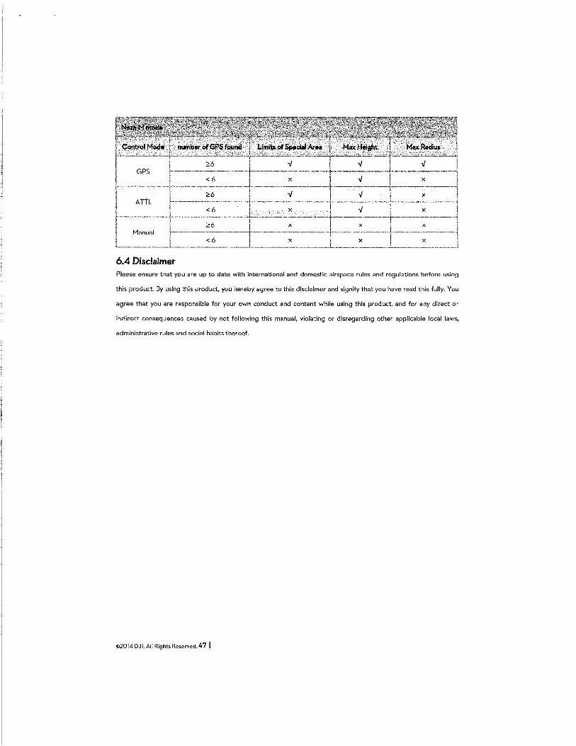
:2:6 v v v GPS
<6 X v X
:2:6 v v X
A TTl. <6 X v X
26 X X X
Manual <6 X X X
6.4 Disclaimer Please ensure that you are up to date with international and domestic airspace rules and regulations before using
this product. By using this product, you hereby agree to this disclaimer and signify that you have read this fully. You
agree that you are responsible for your own conduct and content while using this product, and for any direct or
indirect consequences caused by not following this manual, violating or disregarding other applicable local laws,
administrative rules and social habits thereof.
©2014 DJI. All Rights Reserved. 4 7 I
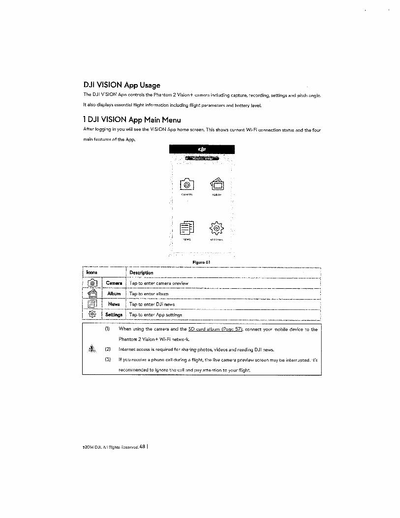
DJI VISION App Usage The DJI VISION App controls the Phantom 2 Vision+ camera including capture, recording, settings and pitch angle.
It also displays essential flight information including flight parameters and battery level.
1 DJI VISION App Main Menu After logging in you will see the VISION App home screen. This shows current Wi-Fi connection status and the four
main features of the App.
AUi!IJM
NfWS SHT!NGS
Figure 61
l I
(1) When using the camera and the SD card album (Page 57), connect your mobile device to the
Phantom 2 Vision+ Wi-Fi network.
(2) Internet access is required for sharing photos, videos and reading DJI news.
(3) If you receive a phone call during a flight, the live camera preview screen may be interrupted. It's
recommended to ignore the call and pay attention to your flight.
©2014 DJI. All Rights Reserved. 48 I

2 Camera Page
[l]
[2]
[3]
[4]·
Figure 62
0 [6]
[7]
t~1 [10]
------·"""""''""""' [ll]
[l]Return [2] Camera Pitch Control [3] Flight Attitude and Radar Function [4] Flight Parameters [5] Wi-Fi Signal
Intensity [6] Flight Battery Level [7] Aircraft GPS Status [8) Micro-SO Card Status [9] Range Extender Battery Level
[10] Remaining Shots [11] Shutter Button [12] Video Recording Button [13] Camera Settings [14] Hide or Show Flight
Parameters
[1] Return 1:1 -Return to the preview page
[2] Camera Pitch Control a -Pitch Control switch is white a tap once to highlight it II and enter Accelerometer Sensor Mode. Tap
again to return to normal.
Nonnal Mode
Tap up arrow a to pitch camera upwards and down arrow B to pitch downwards. Green slider ~ indicates
--~-----------------
Gimbal pitch movement ----+-·----------------------1
I I I
,..... I
--~-~-~----·---~----------··__1
©2014 DJI. All Rights Reserved. 4 9 I
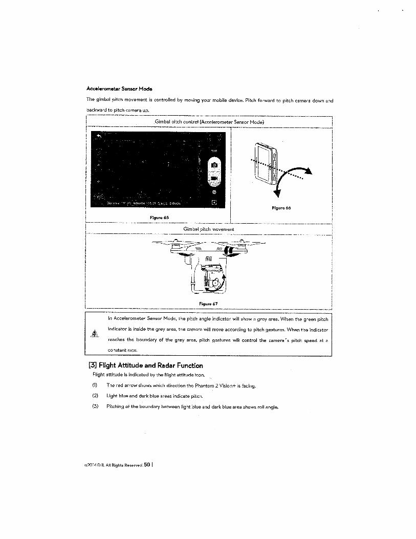
Accelerometer Sensor Mode
The gimbal pitch movement is controlled by moving your mobile device. Pitch forward to pitch camera down and
Gimbal pitch control {Accelerometer Sensor Mode)
In Accelerometer Sensor Mode, the pitch angle indicator will show a grey area. When the green pitch
indicator is inside the grey area, the camera will move according to pitch gestures. When the indicator
reaches the boundary of the grey area, pitch gestures will control the camera 's pitch speed at a
constant rate.
[3] Flight Attitude and Radar Function Flight attitude is indicated by the flight attitude icon.
(1) The red arrow shows which direction the Phantom 2 Vision+ is facing.
(2) Light blue and dark blue areas indicate pitch.
(3) Pitching of the boundary between light blue and dark blue area shows roll angle.
©2014 DJI. All Rights Reserved. 50 I
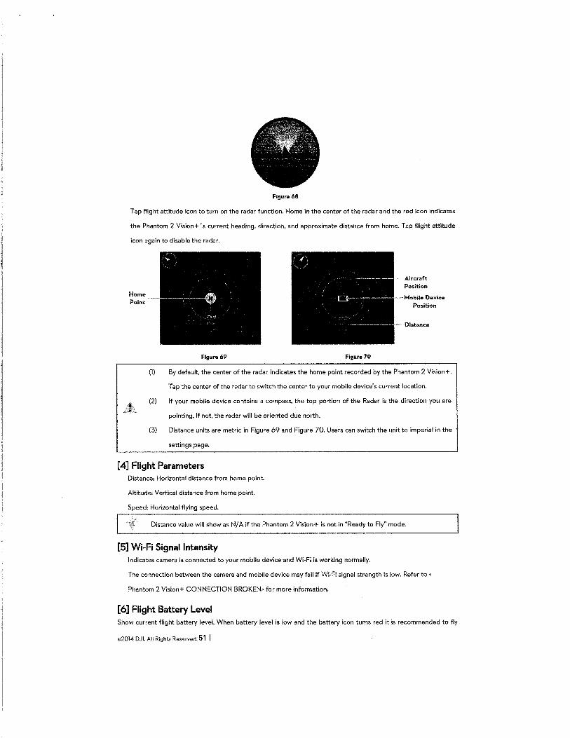
Figure 68
Tap flight attitude icon to turn on the radar function. Home in the center of the radar and the red icon indicates
the Phantom 2 Vision+ 's current heading, direction, and approximate distance from home. Tap flight attitude
icon again to disable the radar.
Home Point
Figure 69 Figura 70
(1) By default, the center of the radar indicates the home point recorded by the Phantom 2 Vision+.
Tap the center of the radar to switch the center to your mobile device's current location.
(2) If your mobile device contains a compass, the top portion of the Radar is the direction you are
pointing. If not, the radar will be oriented due north.
(3) Distance units are metric in Figure 69 and Figure 70. Users can switch the unit to imperial in the
settings page.
[4] Flight Parameters Distance: Horizontal distance from home point.
Altitude: Vertical distance from home point.
Speed: Horizontal flying speed.
Distance value will show as N/ A if the Phantom 2 Vision+ is not in "Ready to Fly" mode.
[5] Wi-Fi Signal Intensity Indicates camera is connected to your mobile device and Wi-Fi is working normally.
The connection between the camera and mobile device may fail if Wi-Fi signal strength is low. Refer to<
Phantom 2 Vision+ CONNECTION BROKEN> for more information.
[6] Flight Battery Level Show current flight battery level. When battery level is low and the battery icon turns red it is recommended to fly
©2014 DJI. All Rights Reserved. 51 I
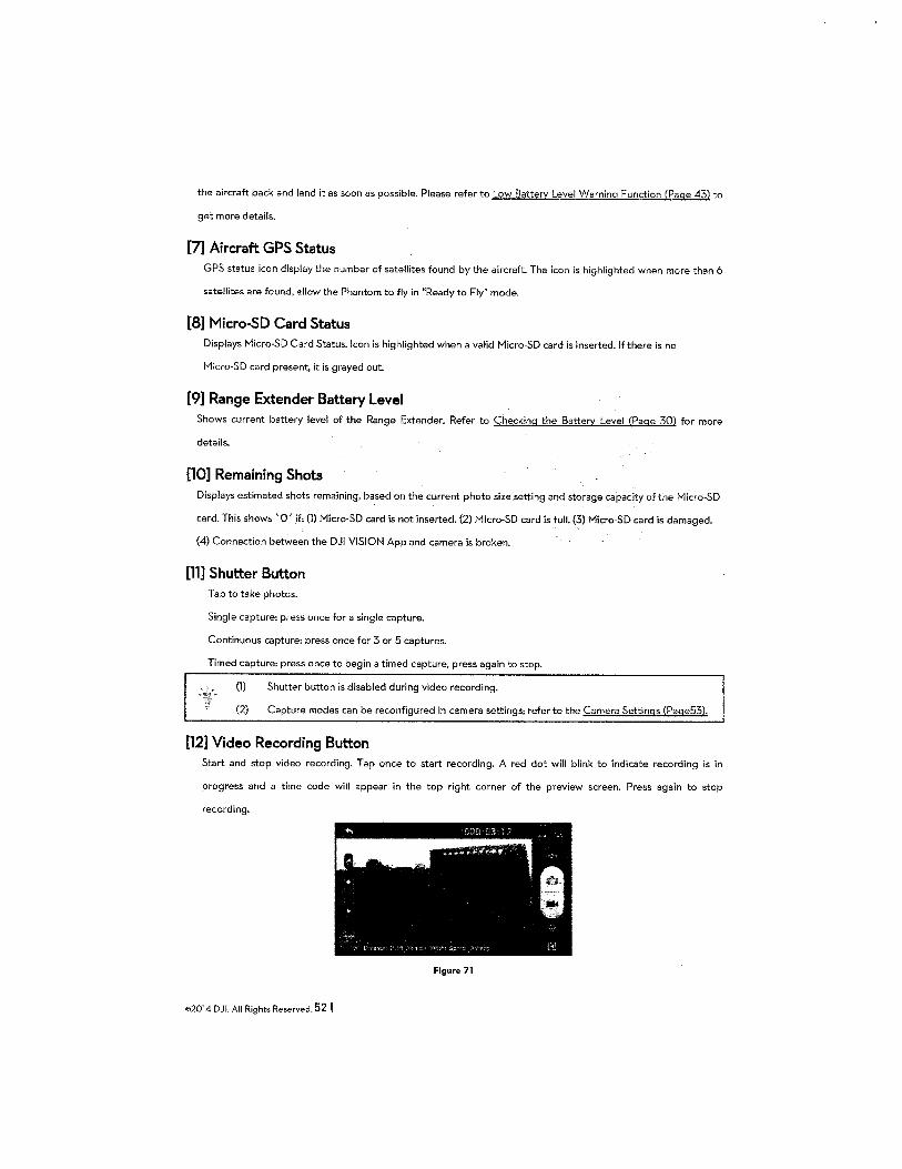
the aircraft back and land it as soon as possible. Please refer to Low Battery Level Warning Function (Page 43) to
get more details.
[7] Aircraft GPS Status GPS status icon display the number of satellites found by the aircraft. The icon is highlighted when more than 6
satellites are found, allow the Phantom to fly in "Ready to Fly" mode.
[8] Micro-SO Card Status Displays Micro·SD Card Status. Icon is highlighted when a valid Micro-SO card is inserted. If there is no
Micro-SO card present, it is grayed out.
[9] Range Extender Battery Level Shows current battery level of the Range Extender. Refer to Checking the Battery Level (Page 30) for more
details.
[10] Remaining Shots Displays estimated shots remaining, based on the current photo size setting and storage capacity of the Micro-SO
card. This shows '0' if: (1) Micro·SD card is not inserted. (2) Micro-SO card is full. (3) Micro-SO card is damaged.
(4) Connection between the DJI VISION App and camera is broken.
[11] Shutter Button Tap to take photos.
Single capture: press once for a single capture.
Continuous capture: press once for 3 or 5 captures.
Timed capture: press once to begin a timed capture, press again to stop.
(1) Shutter button is disabled during video recording.
(2) Capture modes can be reconfigured in camera settings; refer to the Camera Settings (Page53).
[12] Video Recording Button Start and stop video recording. Tap once to start recording. A red dot will blink to indicate recording is in
progress and a time code will appear in the top right corner of the preview screen. Press again to stop
recording.
Figure 71
©2014 DJI. All Rights Reserved. 52 I
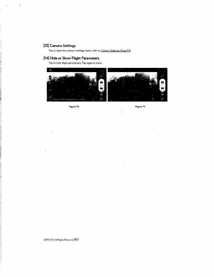
[13] Camera Settings Tap to open the camera settings menu, refer to Camera Settings (Page 53).
[14] Hide or Show Flight Parameters. Tap to hide flight parameters. Tap again to show.
Figure 72 Figure 73
©2014 DJI. All Rights Reserved. 53 I
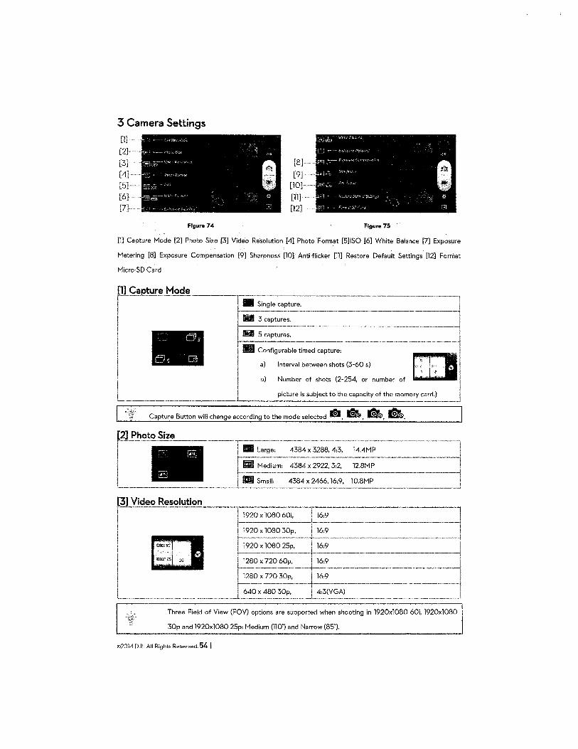
3 Camera Settings
Figure 74 Figure 75
[1] Capture Mode [2] Photo Size [3] Video Resolution [4] Photo Format [S]ISO [6] White Balance [7] Exposure
Metering [8] Exposure Compensation [9] Sharpness [10] Anti-flicker [11] Restore Default Settings [12] Format
Micro-SD Card
~E_tu_r~_M_od_e ___ . ' ·]-~~~ Single capture. ···---------]
! II ------1
!
I ~ .. '~''"'·· ~ ' Scaptures. ------~
Configurable timed capture, J
I a) Interval between shots (3·60 s) ~I
. I b) ::::~. ::b;:~.~::::.:::~::· .: .. ::-1 L..__ __________ ___L._ ___ , ___ _
Capture Button will change according to the mode selected dJ, Q, •. ~-
[3] Video Resolution ~-----·---·---r;;;-~~-i. ---r,~;----------------·----1
I r- I . --------~-----·----j I [D f-~~-~29~~~op. ----~~-- - ---~ I I 1920 X 1080 25p, 16:9 I I ------ ------------------------4
1 " 11280x72060~, 16:9 -------~
L_ J~~~~~;-_rl~----------.-----·-----1 Three Field of View (FOV) options are supported when shooting in 1920x1080 60i, 1920x1080
30p and 1920x1080 25p: Medium (110') and Narrow (85").
©2014 DJI. All Rights Reserved. 54 I
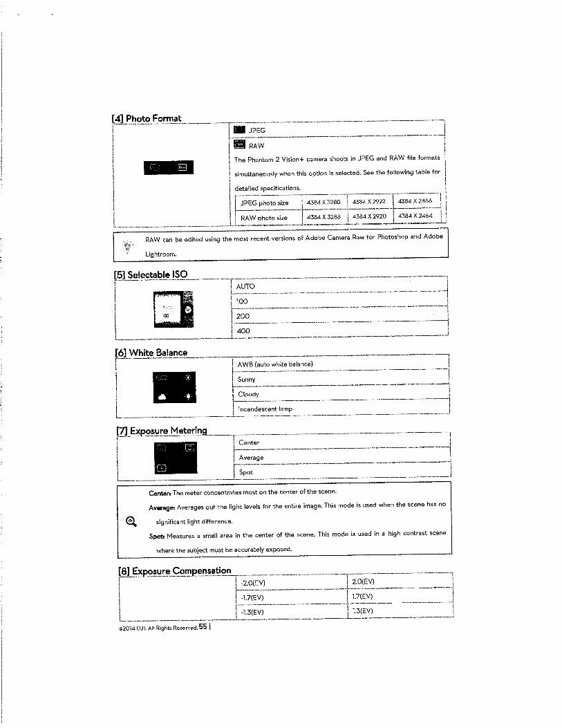
[4] Photo Format
r-----------·----------------------~F-i •. JP~=~~---- ~---~--===-=:·--=~~
I RAW I '
' I - The Phantom 2 Vision+ camera shoots in JPEG and RAW file formats j
I simultaneously when this option is selected. See the following table for j
I I' r=~ailed speci:~:.:.~;-----~-----··---------ll I f-JPEG photo size __ 1 __ L 43~~4 X2922 I 43~~ I I I r;; w photo size 1 4384 X 3288 I 4384 X 2920 ~84 X 2464 I i ·····---·--······-·-··--·-··--·-----··-···--·---~ . --------..L...- -----·--·'
RAW can be edited using the most recent versions of Adobe Camera Raw for Photos hop and Adobe
Lightroom.
Center: The meter concentrates most on the center of the scene.
Average: Averages out the light levels for the entire image. This mode is used when the scene has no
@l significant light difference.
Spot. Measures a small area in the center of the scene. This mode is used in a high contrast scene
where the subject must be accurately exposed.
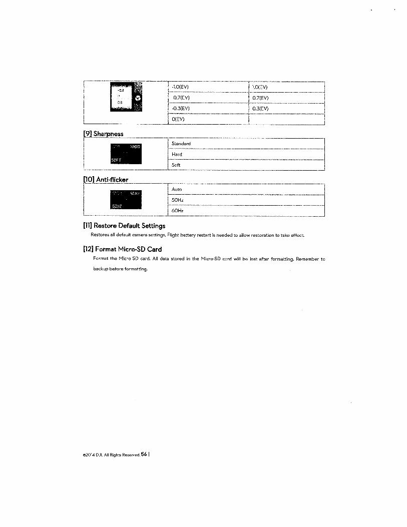
_r---~---------·-.. --~
[11] Restore Default Settings Restores all default camera settings. Flight battery restart is needed to allow restoration to take effect.
[12] Format Micro-SO Card Format the Micro-SD card. All data stored in the Micro-SD card will be lost after formatting. Remember to
backup before formatting.
©2014 DJL All Rights Reserved. 56 I
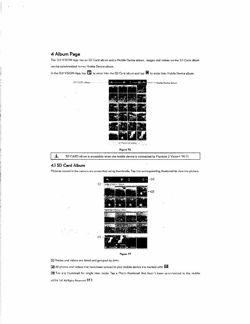
4Aibum Page The DJI VISION App has an SD Card album and a Mobile Device album. Images and videos on the SD Card album
can be synchronized to the Mobile Device album.
In the DJI VISION App, tap E:J to enter into the SD Card album and tap II to enter into Mobile Device album.
SD CARD Album~" , !'-1obi!e Device Album
Figura 76
SD CARD album is accessible when the mobile device is connected to Phantom 2 Vision+ Wi-Fi.
4.1 SO Card Album Pictures stored in the camera are presented using thumbnails. Tap the corresponding thumbnail to view the picture.
·[4]
[1]
[2]· r ~!x <= .. "'~ ' ...
,. - W.:ll'ir:::... a~ 0)'(1::)18 .a~ <:(O:lt'-2 .. 00•4H':
Figure 77
[1] Photos and videos are listed and grouped by date.
[2] All photos and videos that have been synced to your mobile device are marked with Ei [3] Tap any thumbnail for single view mode. Tap a Photo thumbnail that hasn't been synchronized to the mobile
©2014 DJI. All Rights Reserved. 57 I
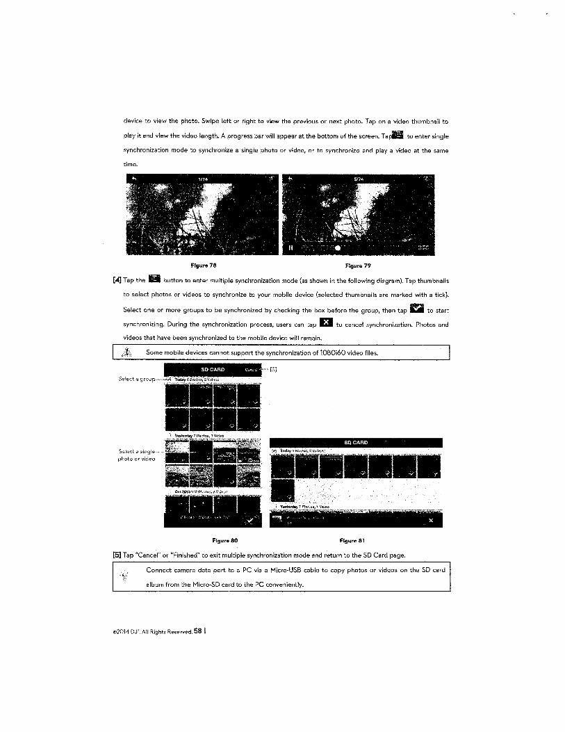
device to view the photo. Swipe left or right to view the previous or next photo. Tap on a video thumbnail to
play it and view the video length. A progress bar will appear at the bottom of the screen. T a pili to enter single
synchronization mode to synchronize a single photo or video, or to synchronize and play a video at the same
time.
Figure 78 Figure 79
[4] Tap the 1!1 button to enter multiple synchronization mode (as shown in the following diagram). Tap thumbnails
to select photos or videos to synchronize to your mobile device (selected thumbnails are marked with a tick).
Select one or more groups to be synchronized by checking the box before the group, then tap a to start
synchronizing. During the synchronization process, users can tap 13 to cancel synchronization. Photos and
videos that have been synchronized to the mobile device will remain.
Some mobile devices cannot support the synchronization of 1080i60 video files.
Select a group,
Se!F:<ct .:~single photo or video
SO CARD c,..,11 ll
. f'c' "\ " - -...,
Figur .. 80
SO CARD
---- ~ -- - - < ~ ~--
"""!! •.·. c ', " X
Figure 81
[5] Tap "Cancel" or "Finished" to exit multiple synchronization mode and return to the SD Card page.
Connect camera data port to a PC via a Micro-USB cable to copy photos or videos on the SD card
album from the Micro-SD card to the PC conveniently.
©2014 DJI. All Rights Reserved. 58 I
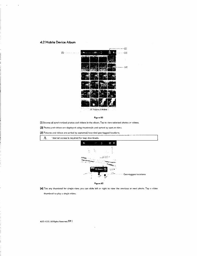
4.2 Mobile Device Album
Figure 82
[1] Browse all synchronized photos and videos in the album. Tap to view selected photos or videos.
[2] Photos and videos are displayed using thumbnails and sorted by capture time.
[3] Pictures and videos are sorted by captured/recorded geo-tagged locations.
Internet access is required for map downloads.
...... I J :: 9
Geo-tagged locations
Figure 83
[4] Tap any thumbnail for single view; you can slide left or right to view the previous or next photo. Tap a video
thumbnail to play a single video.
©2014 DJI. All Rights Reserved. 59 I
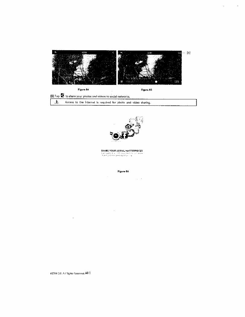
[5]
Figure 84 Figure 85
[5] Tap C3 to share your photos and videos to social networks.
Access to the Internet is required for photo and video sharing.
SHARE YOUR AERIAL MASTERPIECES !....·
Figure 86
©2014 DJI. All Rights Reserved. 60 I
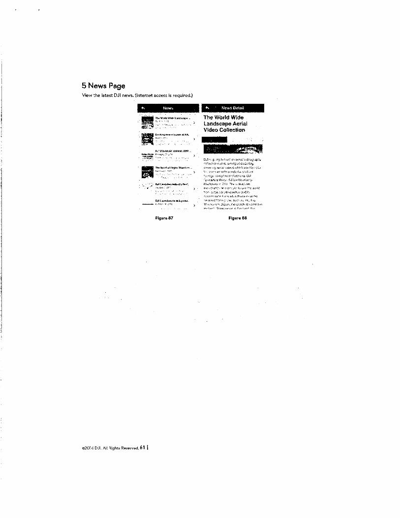
5 News Page View the latest DJI news. (Internet access is required.)
+-. News
DJt ZE~Must. Q;!MiUt. fM ... 11!*'-AA~f.-.;w-•:<
~~>
:.
Figura87
©2014 DJI. All Rights Reserved. 61 I
+-< NewsOetad
The World Wide Landscape Aerial Video Collection
:'.l,i:J,,·~~ t<kf,l,.' ~.~'A•~>~ih'1 \It J. t~"'.>'\ liV> (h.>tfh \•-r··!J;fuiF··~. \~\
Hc•.'J:•h'1 <;!i'r:li'·h<"'"'' 'fi Ftt,,f,lr-.t~
Figure 88
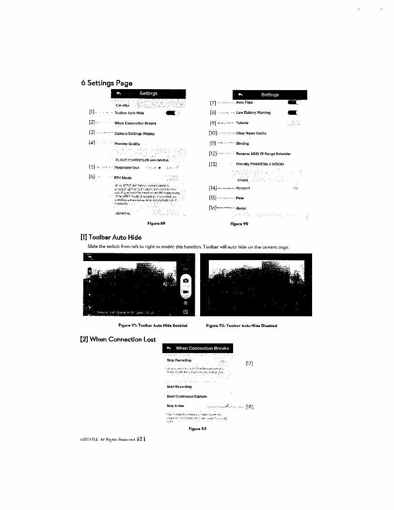
6 Settings Page
[1]
[2]
[3]'
[4]
[5]
[6],
+, Settings
CAMF.RA
Toolbar Auto Hide
"When Connection Breaks
' Camera Settmgs Display
Preview Quality
FPVMode
l'igure 89
[1] T oolbar Auto Hide
- [8]
[9]
[10]·
[11]
Low Battery Warning
llltorial
Clear News Cache
"',,,Binding
-[12] , Rename SSID Of Range Extender
OTHEJl
[14] ·Account
[15]· ·Rate
[16] ,About
Figure 90
Slide the switch from left to right to enable this function. T oolbar will auto hide on the camera page.
Figure 91: Toolbar Auto Hide Enabled Figure 92: Toolbar Auto Hide Disabled
[2] When Connection lost
©2014 DJI. All Rights Reserved. 62 I
+, When Connection Breaks
Start Recording
Start Continuous Capture
Stay-in Idle
Figure 93
[17]
[18]
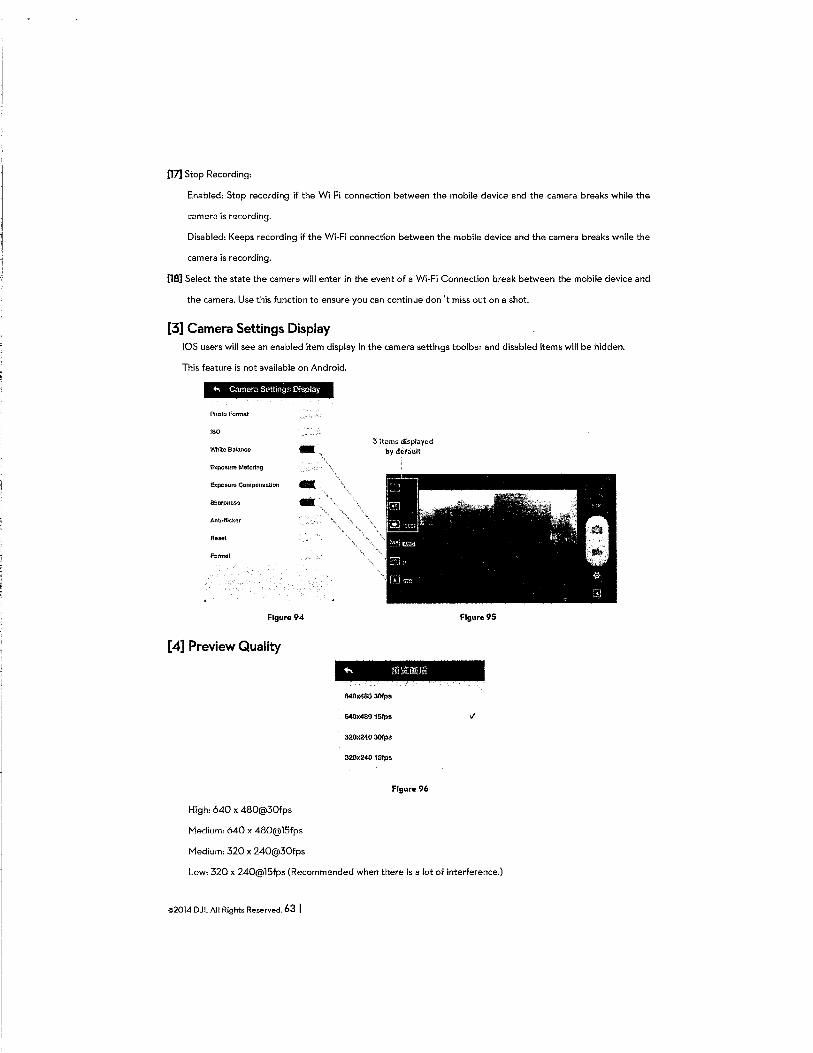
[17] Stop Recording:
Enabled: Stop recording if the Wi-Fi connection between the mobile device and the camera breaks while the
camera is recording.
Disabled: Keeps recording if the Wi-Fi connection between the mobile device and the camera breaks while the
camera is recording.
[18] Select the state the camera will enter in the event of a Wi-Fi Connection break between the mobile device and
the camera. Use this function to ensure you can continue don't miss out on a shot.
[3] Camera Settings Display iOS users will see an enabled item display in the camera settings toolbar and disabled items will be hidden.
This feature is not available on Android .
.._ Camera Settings Oispla)'
Photo Format
ISO
White Balanco -Exposure Metering
Sharpness ~
AtlU41ickar
Fatmat
Figure94
[4] Preview Quality
High: 640 x 480@30fps
Medium: 640 x 480@15fps
Medium: 320 x 240@30fps
3 items displayed by default
640x480 30tps
640x480 151ps
320X240 30tps
320x240 1Sfps
Figure 96
Figure95
Low: 320 x 240@15fps (Recommended when there is a lot of interference.)
©2014 DJI. All Rights Reserved. 63 I
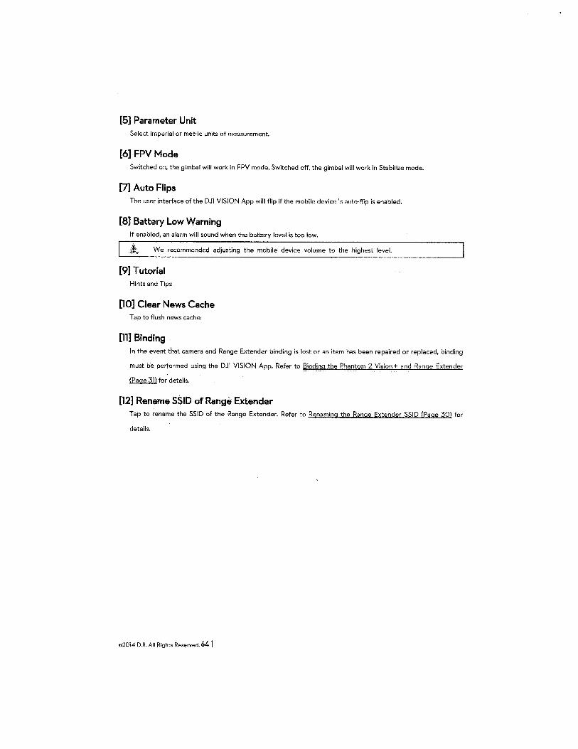
[5] Parameter Unit Select imperial or metric units of measurement.
[6] FPV Mode Switched on, the gimbal will work in FPV mode. Switched off, the gimbal will work in Stabilize mode.
[7] Auto Flips The user interface of the DJI VISION App will flip if the mobile device's auto-flip is enabled.
[8] Battery Low Warning If enabled, an alarm will sound when the battery level is too low.
We recommended adjusting the mobile device volume to the highest level.
[9] Tutorial Hints and Tips
[10] Clear News Cache Tap to flush news cache.
[11] Binding In the event that camera and Range Extender binding is lost or an item has been repaired or replaced, binding
must be performed using the DJI VISION App. Refer to Binding the Phantom 2 Vision+ and Range Extender
(Page 31) for details.
[12] Rename SSID of Range Extender Tap to rename the SSID of the Range Extender. Refer to Renaming the Range Extender SSI D (Page 30) for
details.
©2014 DJI. All Rights Reserved. 64 I
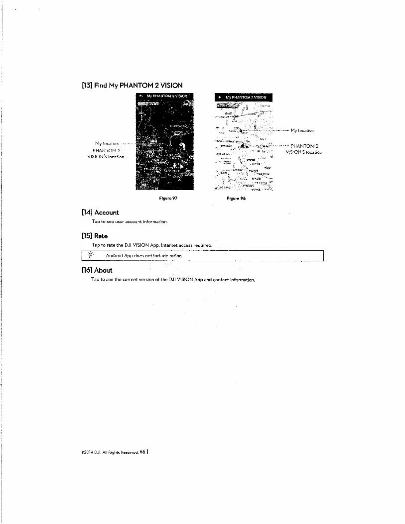
[13] Find My PHANTOM 2 VISION
My locati0r1
PHANTOM 2 VISION'S location
[14] Account
Figure97
Tap to see user account information.
[15] Rate Tap to rate the DJI VISION App. Internet access required.
Android App does not include rating.
[16] About
... My PHANTOM 2 VISION
Figure 98
Tap to see the current version of the DJI VISION App and contact information.
©2014 DJI. All Rights Reserved. 65 I
My location
PHANTOM2 VISION'S location
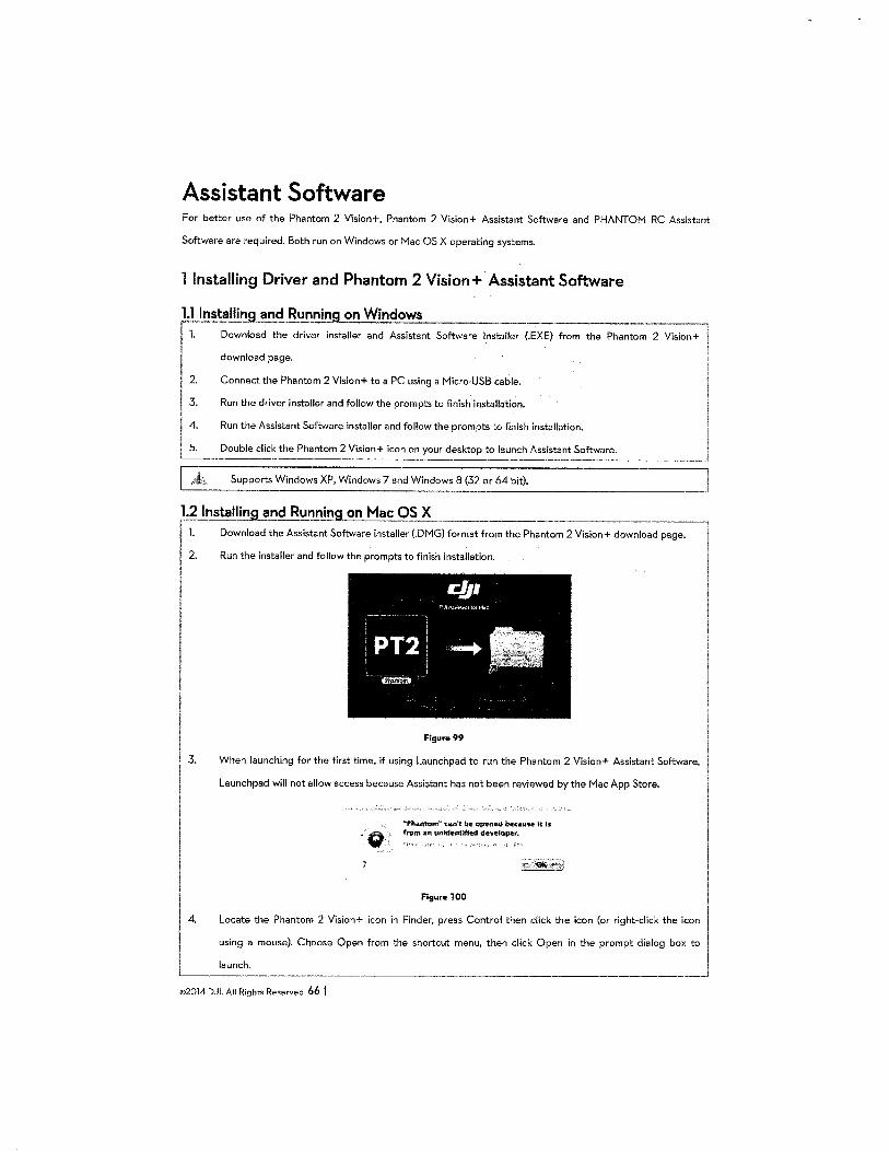
Assistant Software For better use of the Phantom 2 Vision+, Phantom 2 Vision+ Assistant Software and PHANTOM RC Assistant
Software are required. Both run on Windows or Mac OS X operating systems.
1 Installing Driver and Phantom 2 Vision+· Assistant Software
l.ll!Jstalling and Running on Windows --------l 1. Download the driver installer and Assistant Software installer (.EXE) from the Phantom 2 Vision+
download page. . I
1: Connect the Phantom 2 Vision+ to a PC using a Micro-USB cable.
Run the driver installer and follow the prompts to finish installation.
Run the Assistant Software installer and follow the prompts to finish installation.
I __ j I 5. Double click the Phantom 2 Vision+ icon on your desktop to launch Assistant Software. '----··- ·-·--------------
Supports Windows XP, Windows 7 and Windows 8 (32 or 64 bit).
1.2 lnstallin_g_<!nd Run_!!!!!.g on Mac Oc..:S::..cX:..::._ __ ------,
I ~-'
I I I
I I 3.
I
I I I
4.
Download the Assistant Software installer (.DMG) format from the Phantom 2 Vision+ download page. 'I
Run the installer and follow the prompts to finish installation.
Figure99
When launching for the first time, if using Launchpad to run the Phantom 2 Vision+ Assistant Software,
Launchpad will not allow access because Assistant has not been reviewed by the Mac App Store.
-o "'Pho.ntom .. can't be ope_-ned IMcaus-e it ts from a" unfd~JlliftU develope-r.
I FlgurelOO I
Locate the Phantom 2 Vision+ icon in Finder, press Control then click the icon (or right-click the icon_ I'.
using a mouse). Choose Open from the shortcut menu, then click Open in the prompt dialog box to
launch. '-----
©2014 DJI. All Rights Reserved. 66 I
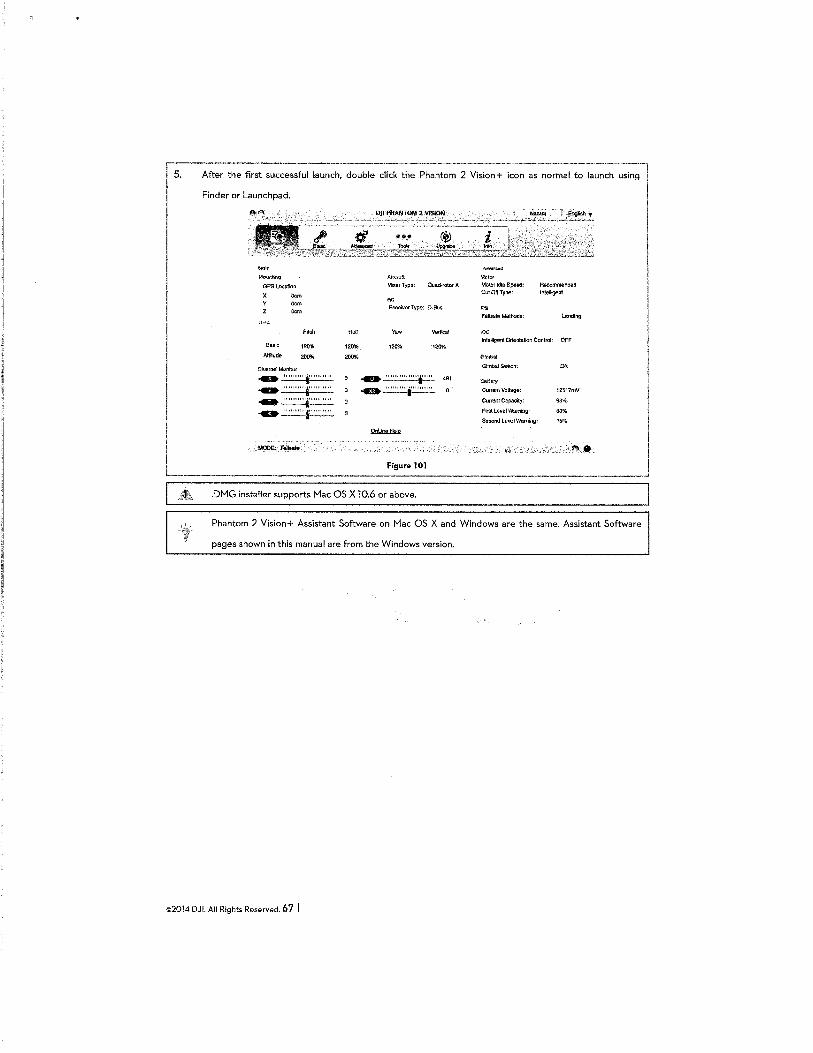
'"" Mot.mlir:g
GPSI..ooation
X
Basic
At1Jtude
oem Oem Oem
Pitch
"'"" .......................... ... '""""'~'""'"' ... ~.:.::.::.:.:::. --~.:.::.::.:.:::.
Roll
120%
A!r·~i'3ft
M!k&rType-~
RC
Receiv&rType: [)..Bus
Yaw Vertical
""" 120%
.......................
Figur .. 101
.DMG installer supports Mac OS X 10.6 or above.
.~.~t:»
Motor !de Speed: Cot Off Type:
!OC
Recommended l'l.tefKgeot
larding
lnleltig.ent Orientation Con!rol: OFF
Gimbal Switch:
"OiltJ:,~t
CtxrentVol•:
Current Capacity:
FirstLeveiWaming.;
Second Level Wlll'niog:
ON
12517mV
96%
30%
1&%
-~ launch using I
I
I Phantom 2 Vision+ Assistant Software on Mac OS X and Windows are the same. Assistant Software
pages shown in this manual are from the Windows version.
©2014 DJI. All Rights Reserved. 6 7 I
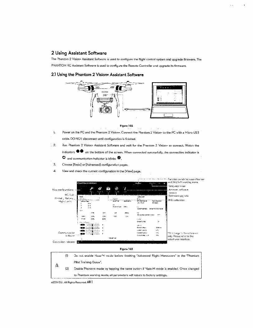
2 Using Assistant Software The Phantom 2 Vision+ Assistant Software is used to configure the flight control system and upgrade firmware. The
PHANTOM RC Assistant Software is used to configure the Remote Controller and upgrade its firmware.
2.1 Using the Phantom 2 Vision+ Assistant Software
Figure 102
l. Power on the PC and the Phantom 2 Vision+. Connect the Phantom 2 Vision+ to the PC with a Micro-USB
cable. DO NOT disconnect until configuration is finished.
2. Run Phantom 2 Vision+ Assistant Software and wait for the Phantom 2 Vision+ to connect. Watch the
indicators • 8 on the bottom of the screen. When connected successfully, the connection indicator is
0 and communication indicator is blinks •.
3. Choose [Basic] or [Advanced] configuration pages.
4. View and check the current configuration in the [View] page.
View configurations
RC, Gain.-
Girnba! , Battery , F!ight t irn!ts
Corrvnunicot.ion
indicator
PHANTOM 2 VI$10N+ Pb "" ' • • - X L...., __ _
"' o... a ® i---~----r • -: ~ 1
1 ,. '
~·'..~';11o!l
il>:.~l
J.~>\
)~..,
-~,--" . ,,.,_ ..
--:~.:::.:.:j.:..::.:.: .. ' -~~, -;:..::.~:.:s::::·:.:::. ..
-"'~" ··~"'
u~~riii~'ep;t!i '..\.i•J'il,::o ,;;!(!t~fllt
0,•lh1Y
C'mr~lll~·~ll".JQC
C:i!tMt(.=!f"•
L.-....a.J!"')ltMl
CIW(>"IlF~;.~...;l
Connection indicator······························ Figura 103
Function switch between Ph;~ntom and NAZA~H working mode
, Language swap
., Accou:Jt, software
version " Firmware upgrade
· IMU calibration
*Thi;, irnDg:::- i::. fc•r n:·rcrcncc:
only. Please refer to the
aclua! user interface.
(l) Do not enable Naza-M mode before finishing "Advanced Flight Maneuvers" in the "Phantom
Pilot Training Guide".
(2) Enable Phantom mode by tapping the same button if Naza-M mode is enabled. Once changed
to Phantom working mode, a II parameters will return to factory settings.
©2014 DJL All Rights Reserved. 68 I
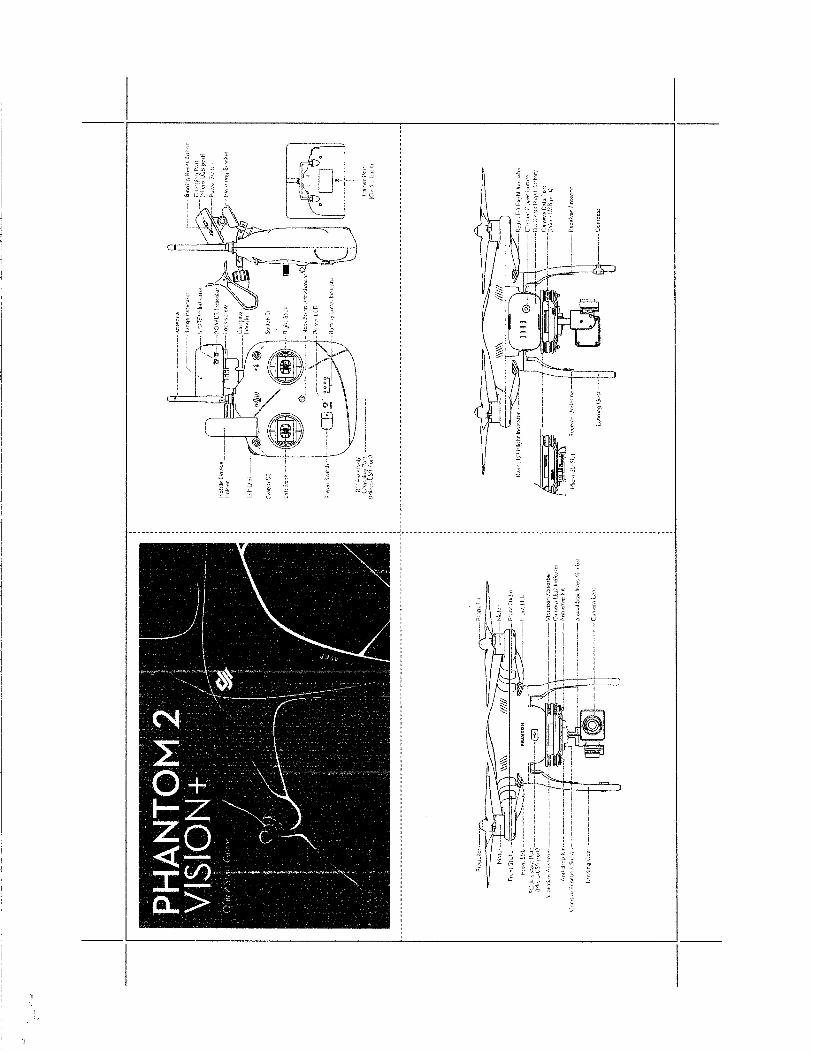
,, ·;:; ;,)
.;;: .::: 3 } :~
' - .. ~- ~ .. ------------------ ---;- ----------'
' ' i :~ 3
~ ~ ·z . .f ~ _3
~ ....
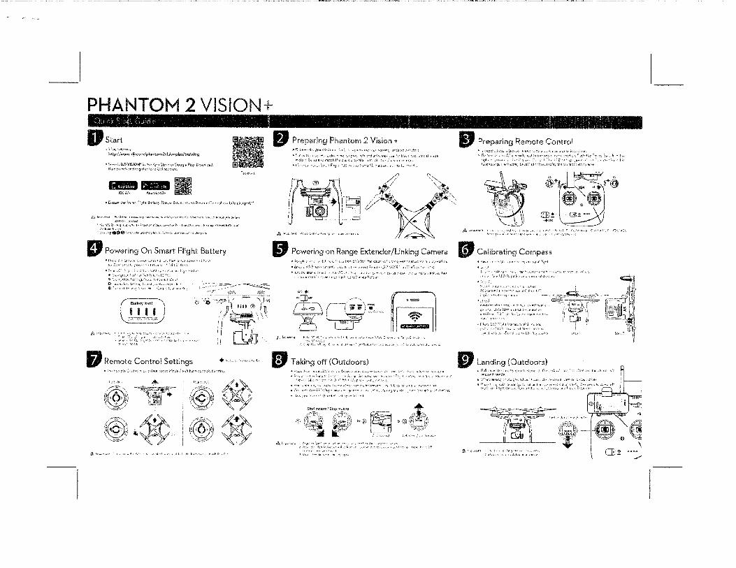
PHANTOtv12 VISION+
Dstart "v;.l"' '<lt~>"t-~ '· http;//www.dji.com/phllntorn2vlsinnplu~/traillln~
n~w·•h,,..l
Tto\;)f•lll~
• [.,~tm:o t<,,, ~:mer\ :;;~~)h! [i.;>~!tur :-·. J}.;:.ort"" r::-l\,1\·)·.-r <1'!(1 Rr:r .. •)'tc: (" ;:rttn..! m<~ fJtf<,· ,),~~~l'<cl."
_;'];._ ltp · •t•·>~. ~,_,, 5>'-F• 1 '"1'»''"1 f!''·"' •: . .,tc:, ''<I"'"·'''• ·";-,d rh•, ··:w.'o'"'' · e~C ''•'~""~· r;..~r,·~•Jhlt t·~'~•~ •• :~"\•''"'•l'l:>.b::.t
D Powering On Smart Flight Battery
1,,;:]o.''t•j•,··
---J Batill.rylfWel
( ,~JJ, •. !-, ---
,:g'l;, :~p .. •:>•+
c ;~t:~}~~; --~)~ ~ . ,. IT 1 111 e Col j n"'
·:Y"~--1
:I'"'S~<-'!i ClJJ
D Remote Control Settings +•·
if®:\ \:~-'
'@/-;~---\ li ~""'·· "i \! 'i'' ~:: '•---E~el:..-"
w.,..,.,,,,J· ·, ...
t t•bil' ~-~·- I<> :·1•;,j•, .' i;":"fl r J''"• '; ~ t;.;.·, ncr·· t.t!'< •.
""' ~~~.:·--
"'!~(· ib,,.J
·® (@,''":."~-, I~ •-""" ,\ ~--..-vt..:l \ v ' \,··~!!~-£.·/
@·'"'";:,-.\
( ,()> ~) '-- ... ,~~f;,-·/
® ' " ~ ~~~
fJ Preparing Phantom 2 Vision + •'-:
"•:Ot.'-.t'::<-V
•1 1··~""· ,,JLo:~··· tr-·f,,·~~~t "'" ,,,r•,-?,_,~,;; <•.·i<..''•".'''r·
~rtf . // \
~·61J· ,<~)!(~7' ~~---~-· 0 Jlt •. \, ......
A''""''"" '''""'''"'•''"·'' ,,. "' ·"-""' ,.. ~
liJ Powering on Range Extender/Linking Camera
~CD- . ---- -.. • = o'+ ~
X~!:- ri1 t\ 1 .. ·~~""'* J "'' .. ,~,l ,, ,. ~ ~~ l' ( ! ... '·
BJ Taking off (Outdoors)
. ,., l·, f 1'.'• ·,: , .•• ,~ •• ''•'~··· • -· )>\
Sfufl:l'niJtors.'S!U;J:llV!c•l.,;
0> :~~t ?@ ~-----.... ., ,§;t, l !>@(\~~-;-,,,
------~- \;;:~q~7i~~~: ,::.:.:-.. _.,..; l·!"· .. ,
.4}, l<r-~~:tzf,t.
IJ Preparing Remote Control
[B!··· <+ON
A L;,.,,~,;~.,·· .. ,., .•,•,·•~ W' ~
IJ Calibrating Compass ~ >,;,..,.,
~ ·''"~ .:
~::; :,Li.r.
•.'.•e:l•::.
lf,r.:''''""':·r.' ,::·.
ql \!\
i. /1~? .~~,,_~~~:~t~. ~~co~.:::f~~~
., :, .. ~· "". '') !l ,bfi~l ~ i J :. " ··, n<a~ !>' '; r·f •J 'I '•''--""~-- -~<!!/~ ; ·r ~ ,. \;l ~ i' "'···"' :.ff' r: ,Jh! :.•.l•<;!t:~r:. :.•>.; ,:, .,.;!;- '"·
'w~J<.·•·.· -~ _,,
lfJ l..anding (Outdoors) ~ l'dl ~:'J I" :hr• :·v~!!~~ !<; •,·~f.t'·'" Pw ·::, ,,;: !i';cl ,.,.,,,! ·:,;
.A·
I ' •or,d ~ !•<<:•1<1\'
~ 'v\'··:.\ l;>f'u'''' ·.• ~~ . ., "l'"•·"·,;i j;c-1 f •• fl' ):1<
H !'>.v t
~''"' s "·' .
f, ,:, c:,,, ";:;1~,,
\ ··::·.1·'•''-''. CB.e.
/
PHANTOM PILOT TRAINING GUIDE
Earning Your Stripes Vl.l
Learn More: www.dji.com
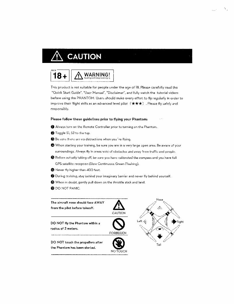
& CAUTION
This product is not suitable for people under the age of 18. Please carefully read the
"Quick Start Guide", "User Manual", "Disclaimer", and fully watch the tutorial videos
before using the PHANTOM. Users should make every effort to fly regularly in order to
improve their flight skills as an advanced level pilot ( ***) . Please fly safely and
responsibly.
Please follow these guidelines prior to flying your Phantom:
G Always turn on the Remote Controller prior to turning on the Phantom.
@ Toggle Sl, S2 to the top.
8 Be sure there are no distractions when you're flying.
0 When starting your training, be sure you are in a very large open area. Be aware of your
surroundings. Always fly in areas void of obstacles and away from traffic and people.
0 Before actually taking off, be sure you have calibrated the compass and you have full
GPS satellite reception (Slow Continuous Green Flashing).
(!) Never fly higher than 400 feet.
fj During training, stay behind your imaginary barrier and never fly behind yourself.
@ When in doubt, gently pull down on the throttle stick and land.
f) DO NOT PANIC.
The aircraft nose should face A WA V
from the pilot before takeoff.
DO NOT fly the Phantom within a
radius of 2 meters.
DO NOT touch the propellers after
the Phantom has been started.
& CAUTION
(Sl Left
FORBIDDEN
@ Tail
NO TOUCH
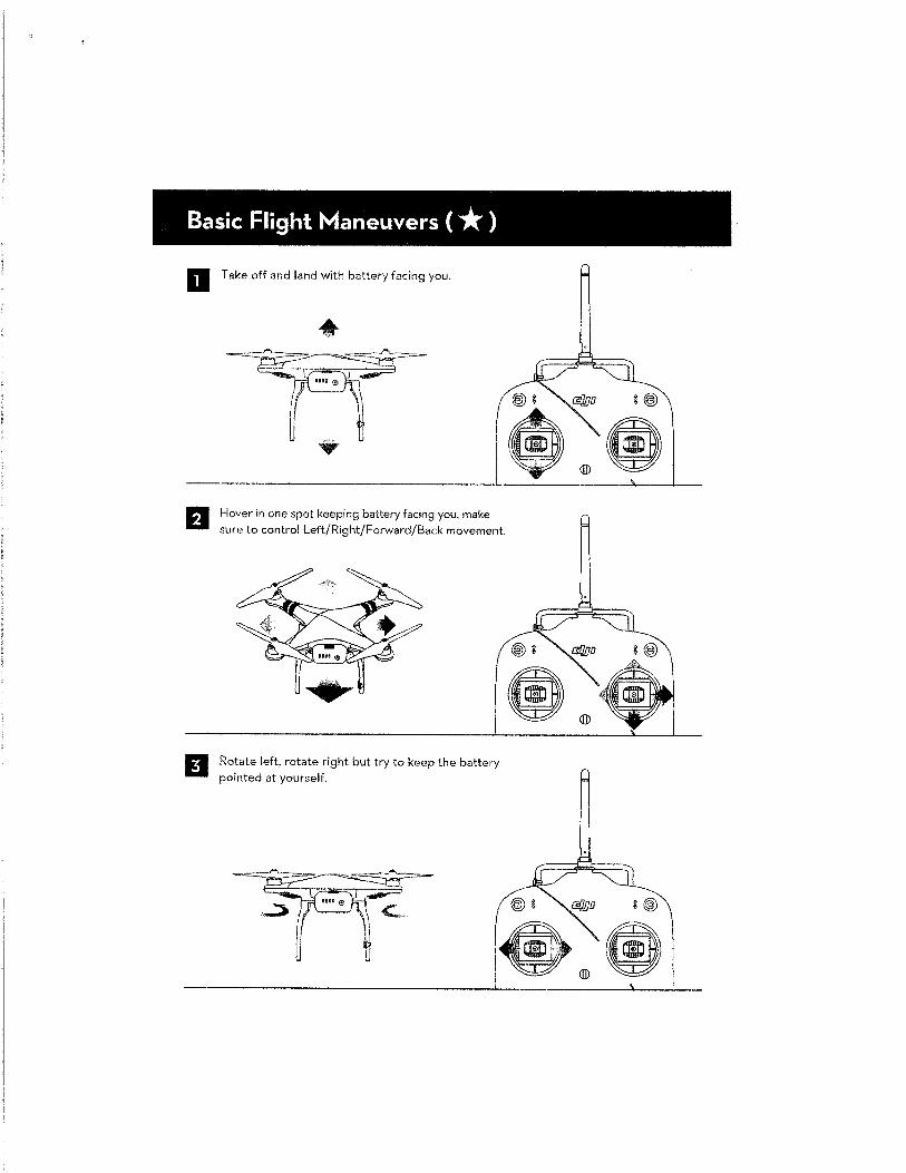
Basic Flight Maneuvers ( *) a Take off and land with battery facing you.
Hover in one spot keeping battery facing you, make sure to control Left/Right/Forward/Back movement.
Rotate left, rotate right but try to keep the battery pointed at yourself.
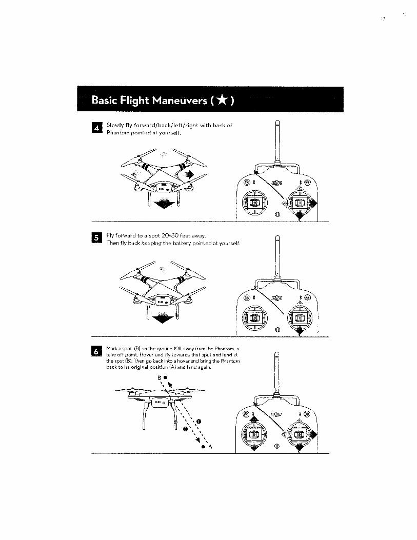
Basic Flight Maneuvers ( * ) II Slowly fly forward/back/left/right with back of
Phantom pointed at yourself.
Fly forward to a spot 20-30 feet away.
I
Then fly back keeping the battery pointed at yourself.
Mark a spot (B) on the ground lOft away from the Phantom 's take off point. Hover and fly towards that spot and land at the spot (8). Then go back into a hover and bring the Phantom back to its original position (A) and land again.
(i
~ I~
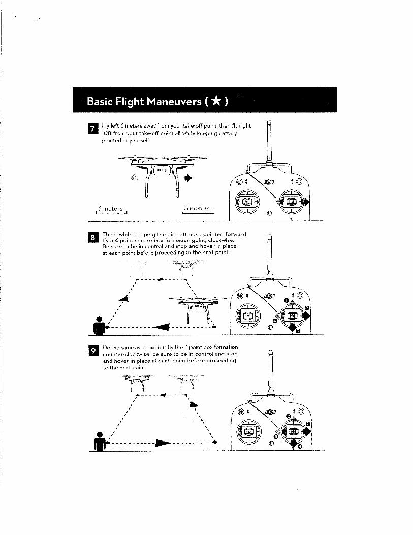
.,
Basic Flight Maneuvers ( *) II Fly left 3 meters away from your take-off point, then fly right
lOft from your take-off point all while keeping battery
pointed at yourself.
3 meters 3 meters
El Then, while keeping the aircraft nose pointed forward, fly a 4 point square box formation going clockwi~e. Be sure to be in control and stop and hover in place at each point before proceeding to the next point.
I
,
~ , , I
, I
-----~-----. I
Do the same as above but fly the 4 point box formation counter-clockwise. Be sure to be in control and stop and hover in place at each point before proceeding to the next point.
I I
I
~~ ~
' I
I
, I
------+----"1 , ' ~
' ~ ' ' '
I \
-----------~----------·
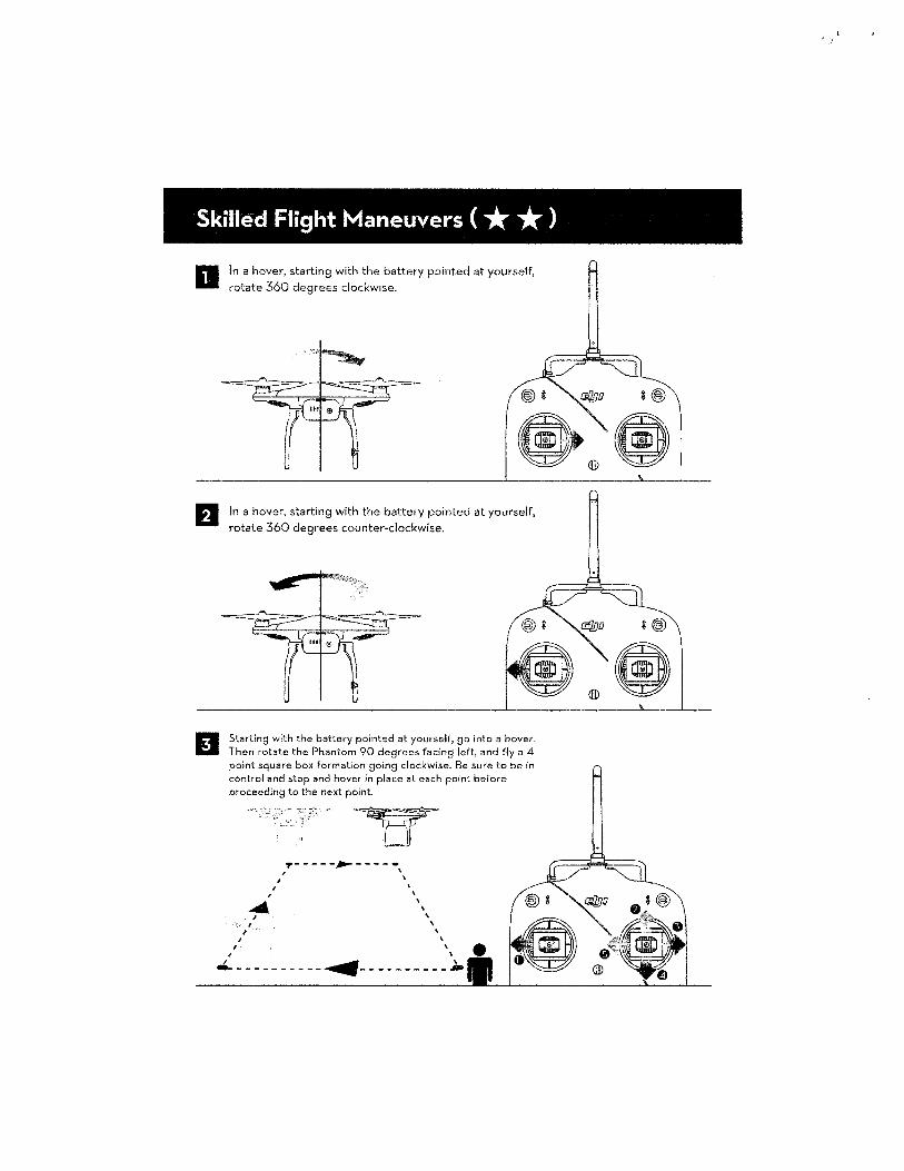
Skilled Flight Maneuvers ( * * ) D
El
In a hover, starting with the battery pointed at yourself, rotate 360 degrees clockwise.
In a hover, starting with the battery pointed at yourself, rotate 360 degrees counter-clockwise.
Starting with the battery pointed at yourself, go into a hover. Then rotate the Phantom 90 degrees facing left, and fly a 4 point square box formation going clockwise. Be sure to be in control and stop and hover in place at each point before proceeding to the next point.
~- ----,_ -----, ' ' \
' \ ' \ ' \
' , \
el----------~----------~
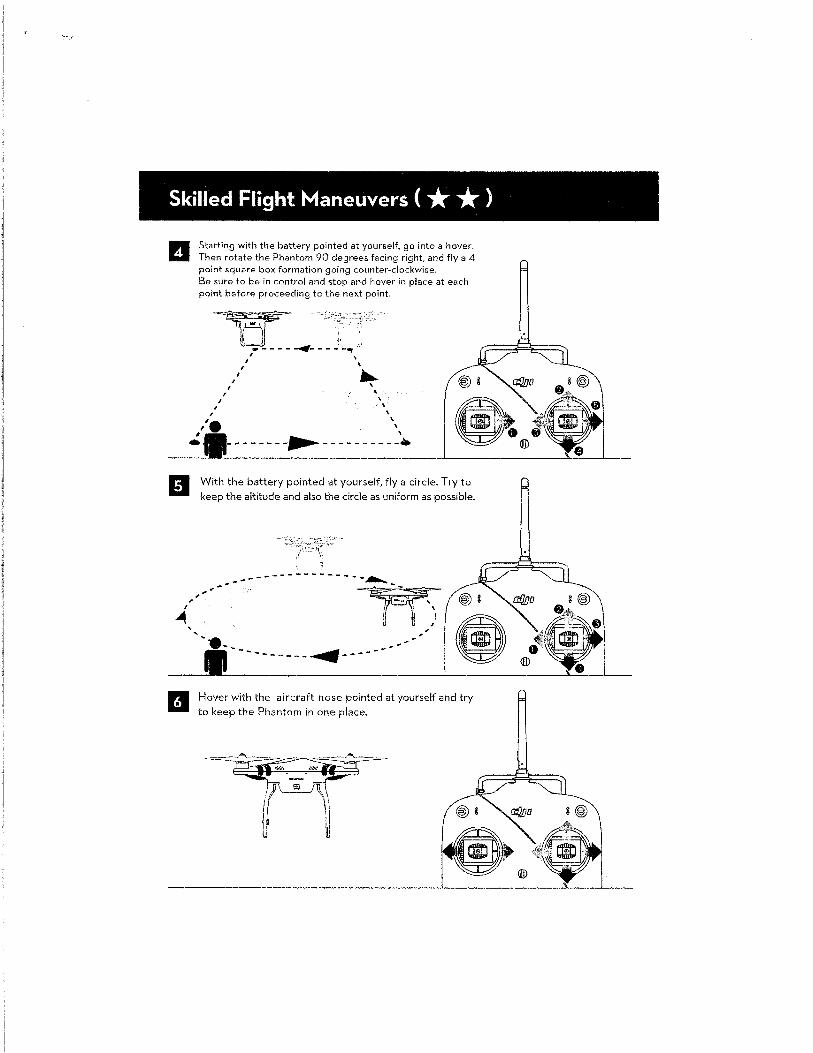
Skilled Flight Maneuvers ( * * ) II
' '
Starting with the battery pointed at yourself, go into a hover. Then rotate the Phantom 90 degrees facing right, and fly a 4 point square box formation going counter-clockwise. Be sure to be in control and stop and hover in place at each point before proceeding to the next point.
~w- -.· ~ :, ..
"==----- __._-- ..:: .. "t I \
/1 ,...._ I \
/ ' , \ I \
\ \
' \ -------~-----------
With the battery pointed at yourself, fly a circle. Try to keep the altitude and also the circle as uniform as possible.
-----------------~~w--=--· ' I \ I
I
----------~----- ---
Hover with the aircraft nose pointed at yourself and try to keep the Phantom in one place.
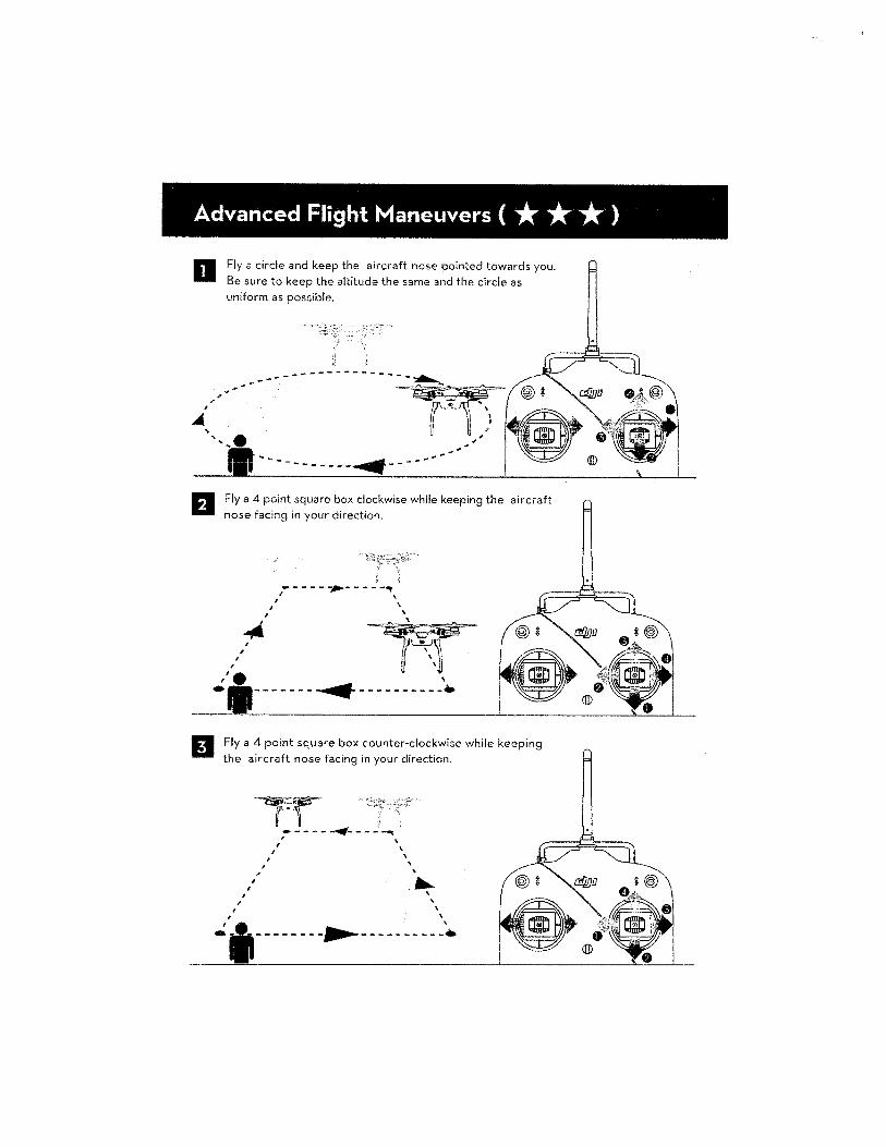
Advanced Flight Maneuvers ( * * * ) II Fly a circle and keep the aircraft nose pointed towards you.
Be sure to keep the altitude the same and the circle as uniform as possible.
Fly a 4 point square box clockwise while keeping the aircraft nose facing in your direction.
-----~- - -- -"' f ' I \
/ \
/1* ~ ,' e , ·-------- ........ -- ---------
IJ Fly a 4 point square box counter-clockwise while keeping the aircraft nose facing in your direction.
I I
I
~ ~ ll . .
I
' ,
' I
_____ ..., _____ "' '
' ' ' \
' ' ·- ---------~-------------. \
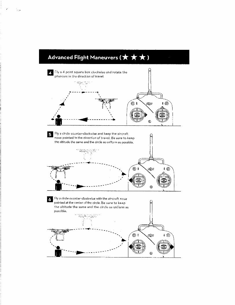
Advanced Flight Maneuvers ( * * * ) II Fly a 4 point square box clockwise and rotate the
phantom in the direction of travel.
I
' , • I I
I
.. -- - - ~-- - - -<t , ' -~-
' ' ' - -- ---........ ------ ---_._
~H ~@
~>®• ~~ Fly a circle counter-clockwise and keep the aircraft
nose pointed in the direction of travel. Be sure to keep the altitude the same and the circle as uniform as possible .
........... ' .. ' ~ I
~-----...-------------
B Fly a circle counter-clockwise with the aircraft nose pointed at the center of the circle. Be sure to keep the altitude the same and the circle as uniform as possible.
-------...--------------
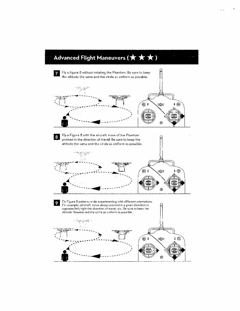
Advanced Flight Maneuvers ( * * * ) II Fly a figure 8 without rotating the Phantom. Be sure to keep
the altitude the same and the circle as uniform as possible.
-'. ~ '~,'
',~~-~---~-----------~
Fly a Figure 8 with the aircraft nose of the Phantom
pointed in the direction of travel. Be sure to keep the
altitude the same and the circle as uniform as possible.
-~"37~:c"'~-~--..., -----~ -~ "'+ -~~ ', ;I J " L J -- -~ -_: ::.-:.·-----"~----- _........_-_- --
-'. ' .. ~ ,_, _______ ~ -------- ___ ..
Fly Figure 8 patterns while experimenting with different orientations. For example, aircraft nose always pointed in a given direction or opposite/left/right the directiotl of travel, etc. Be sure to keep the altitude thesame and the circle as uniform as possible.
' ' ' - ,
''------~------------
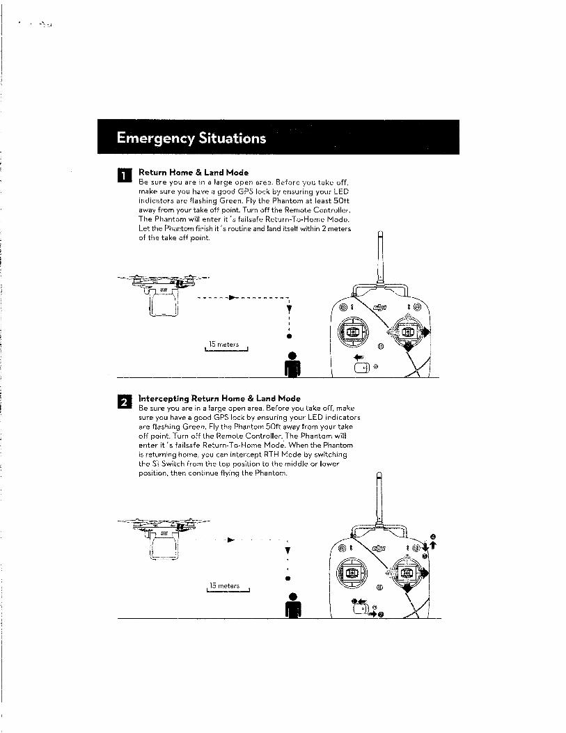
Emergency Situations
a
El
Return Home & Land Mode Be sure you are in a large open area. Before you take off, make sure you have a good GPS lock by ensuring your LED indicators are flashing Green. Fly the Phantom at least 50ft away from your take off point. Turn off the Remote Controller. The Phantom will enter it's failsafe Return-To-Home Mode. Let the Phantom finish it's routine and land itself within 2 meters of the take off point.
• 15 meters
Intercepting Return Home & Land Mode Be sure you are in a large open area. Before you take off, make sure you have a good GPS lock by ensuring your LED indicators are flashing Green. Fly the Phantom 50ft away from your take off point. Turn off the Remote Controller. The Phantom will enter it's failsafe Return-To-Home Mode. When the Phantom is returning home, you can intercept RTH Mode by switching the Sl Switch from the top position to the middle or lower position, then continue flying the Phantom .
..... 0 ' ,
' • (I
115 meters
\ ~-• II

www.dji.com