august 2013€¦ · water systems, power generation, ... photovoltaic system, “wil- ... paar...
TRANSCRIPT
INTERNATIONAL BUILDING EXHIBITION HAMBURG
Smart Material House
Smart is Green August 2013

2
Published by:
IBA Hamburg GmbH
Am Zollhafen 12
20539 Hamburg
TEL. +49(0)40.226 227-0
FAX +49(0)40.226 227-315
www.iba-hamburg.de
Date:
August 2013
Project coordinator:
Hubert Lakenbrink
Concept and design:
IBA Hamburg GmbH
Jens-Phillip Petersen
Text and editing:
IBA Hamburg GmbH
Jens-Phillip Petersen
Christian Roedel
Imprint

3
A INTRODUCTION
A.1 SMART MATERIAL HOUSES
A.2 SMART IS GREEN PROJECT OUTLINE
B SMART IS GREEN PROJECT DETAILS
B.1 ARCHITECTURAL CONCEPT
B.2 SMART MATERIAL CONCEPT
B.3 BUILDING SERVICES CONCEPT
B.4 PLANNING PROCESS
B.5 ASSESSMENT
PICTURE CREDITS
4
4
6
8
8
11
18
20
22
24
Contents

4
“Smart materials” are materials, material
systems, and products that can be derived from
them which behave not in a static but a dynamic
way, in contrast to conventional building mate-
rials. In other words, because of their nature,
these materials react to changing environmental
conditions and adapt to them. These special
characteristics result from physical or chemical
influences, such as varying temperatures or sun-
light falling on the building material.
The building envelope is one of the most crucial
elements: the use of smart materials in the
façade can enable energy and material flows to
be improved and kept as small as possible, since
a large proportion of these materials draw
energy directly or indirectly from the surround-
ing environment.
Smart materials can be found in nature.
Microalgae, for example, can be bred in the glass
sections of façades: they then use photosynthe-
sis to turn solar thermal energy into heat energy,
biomass, and heat. The façade itself becomes
part of the building services.
A “Smart Material House” is a new form of
residential building in which adaptable architec-
tural designs can be combined with intelligent
technologies and construction materials. As one
of the main themes of the “Building Exhibition
within the Building Exhibition”, these constitute
an architectural pilot project, using four exempla-
ry building types to show how new technological
approaches can be translated into a forward-
looking architectural language, and traditional
techniques reinterpreted.
As its starting point for the “Smart Material Hou-
ses” theme, the International Building Exhibition
Hamburg (IBA) presented the following basic
ideas. Smart materials are active, with a transfor-
mative character. They respond to changing envi-
ronmental conditions. In an intelligent interaction
with “smart technologies”, this process can be
extended to the level of networked building ser-
vices, and can monitor and optimise the energy
and material maintenance.
For this purpose, the existing categories of mate-
rials must be considered afresh, because smart
materials, being active, take on opposing proper-
ties and functions at different times. Material and
technological innovations in architectural history
were always associated with a fundamental
change in what architecture could and should be.
These days, it can be observed that sustainability
is the background to many design decisions.
• Smart materials and smart technologies,
through their adaptive functions, make it
possible to control energy and material
flows sustainably.
• The adaptability of smart materials endows
time processes with great significance.
• A performative understanding of materials
and technologies enables and fosters a
new approach to the architectural design
process.
A paradigm shift towards decentralised infra-
structure systems is becoming apparent. By
decentralisation we mean the integration of
urban functions into building technology. Water
systems, power generation, the use of waste
heat, miniature pumps, and combined heat and
power are installed and deployed locally or in
the immediate vicinity. Much of the energy
consumed in buildings is to be recovered in the
future from existing local anergy, to reduce the
proportion of high exergy.
The infrastructures of the city need to be re-
thought and reorganised in this context.
• Through the integration of urban functions
into building technology, the house becomes
an actor in a (communicative, i.e. feedback)
network. Accordingly, it performs additional
functions, such as being a “power plant”,
providing “energy storage” or comprising a
“communicative place” in the urban context.
A Introduction
A. 1 Smart Material Houses

5
• The building envelope is the central element
of the energy exchange between inside and
outside. It controls inflowing and outflowing
currents of energy and the circulation of
material. Using smart materials and smart
technologies, building envelopes can
• actively regulate energy and material flows.
• Since the beginning of the modern period,
building services have been bundled away,
centralised and thus often rendered invisib-
le. With the proliferation of smart materials,
the material surface can itself become a
medium carrying energy and information.
• The new technologies make it possible to
multiply building services and distribute
them to various surfaces. Materials become
dynamic infrastructures that can produce
variable, partly contradictory effects.
• With the extension of multifunctional sur-
faces, the time factor becomes an integral
part of the design and simultaneously
makes it possible to use space and buildings
in hybrid ways.
• Along with the increasing importance of
time processes, an “open layout” can be
changed into a “reconfigurable layout”.
• Reconfigurable layouts are generated from
the mutability of the space, the transform-
ability of the materials, and the adaptabi-
lity of the technologies, no longer solely
through their (static) openness to different
uses.
• There is an emphasis on the “aesthetics of
the phenomena”, which mainly focuses on
the behaviour of materials. It is not impor-
tant how the material presents itself, but
when it makes its appearance.
The architectural and building services concepts
underlying the “Smart is Green” will be set out
in detail in this booklet. The planning process will
also be explained precisely, as various changes
were made between the design stage and the im-
plementation of the model project. The reasons
behind these changes were technical, financial,
or functional, meaning that some of the original
targets had to be adjusted.
Model projects are particularly liable to undergo
planning changes; indeed, besides presenting
innovative end products, building exhibitions
seek to test construction methods and processes.
Only when the planning process is examined is it
possible to ascertain whether a model building
project can serve as a good example of the use of
“smart” materials in the twenty-first century, or
if the concept needs to be reworked. In addition
to setting out technical details for experts, this
booklet is intended to provide an objective as-
sessment of whether the model project “Smart is
Green” fulfils this aim, and whether and to what
extent it has ultimately succeeded in achieving
the goals set out before the planning stage.
After this short introduction the “Smart is Green”
apartment block will be presented in brief, and
then explained in detail. The architectural and
building services concepts will be introduced
first, followed by a description of the planning
process, and then the evaluation of the model
project. The presentation will focus in particular
on the energy concept and the materials used for
storing energy.

6
FEATURES
• Energy generation units on the roof and façades as part of the architectural concept
• Use of phase-change materials (PCMs) to store energy
• Flexible layout configurations that are adaptable to the needs of the residents
Each of the four family-friendly terraced houses
“The aim of the building is to make the aest-
hetics of energy transformation visible, and
to create flexible building structures that can
be used by people of all ages.” Michael Ziller,
architect
The façades and roof of the “Smart is Green”
structure are an active part of the innovative
building services concept. They use different
technologies to generate energy that can be
used directly by the building, or even fed into
the Wilhelmsburg energy grid. The focus here
is on the use and storage of thermal energy to
supply heat to the block.
In addition, the development and ground plans
are designed to be flexible, and can be adapted
to the individual requirements of the residents.
Structure follows function to suit everyday
needs. The building can be adapted to follow
changing technological needs and the residents’
requests, as the demand arises.
Fig. 1: View from the southeast, June 2013
Fig. 2: View from the southwest, May 2013
A. 2 Smart is Green Project Outline

7
PROJECT PARTNERS
Architecture
• zillerplus Architekten und
Stadtplaner, Michael Ziller
Architekt BDA, München
Investor
• Behrendt Wohnungsbau
KG, Hamburg
• Sparda Immobilien GmbH,
Hamburg
Technical Building Services
• PINCK Ingenieure Consul-
ting GmbH, Hamburg
• Ingenieurbüro Hausladen
GmbH, Kirchheim
Construction Materials Part-
ners
• Christian Fischbacher
GmbH, St. Gallen
• Outlast Europe GmbH,
Dörken
• Oliver Wagner Innenein-
richtung GmbH, Hamburg
Other Project Partners
• Hamburg Energie GmbH,
Hamburg
• Realisation: Andresen
Garten und Landschafts-
planung, Hamburg
• Competition: Burger
Landschaftsarchitekten,
München
PROJECT DATA
Project Costs
• approx. € 4.4 million
Plot Size
• 1,250 m2
Gross Floor Area
• 1,990 m2
Size of the functional units
• 86 - 127 m2
Energy Standard
• Efficiency House Plus,
built to a Passive House
standard
Energy Supply
• Solar thermal energy,
PCM energy storage, and
photovoltaic system, “Wil-
helmsburg Central Energy
Network” district heating
Construction Period
• December 2011 - March
2013
Structural Design/Fire safety
• Wetzel & von Seht Ingeni-
eurbüro für Bauwesen VBI,
Hamburg

8
The “Smart Material House” by zillerplus
Architekten grapples with a wholly modern
theme – the systematic separation between the
supporting framework, shell, and fitout elements
– in a new way.
The compact structure, a solid construction,
has long-span ceilings in order to ensure that
the apartments are separated as flexibly as
possible. On the southern side is a continuous
balcony area, which forms its own layer, like a
multi-storey veranda. The south façade has a
large proportion of glass surfaces for a passive
house, endowing the building with high resi-
dential value. The east and west façades have
an open appearance, while the north façade
appears more closed, with the surface broken
up by coloured sheet metal panels. Features
of the design are the vertical gardens on the
south façade (climbing hydrangea on trellises),
which are echoed by the sheet metal panels of
the same size on the other sides, so that all four
façades are brought together by these rectangu-
lar elements.
The south side is arranged in three layers from
the outside to the inside: a planted façade
element serves as protection against the heat in
summer, insulated glazing protects against heat
and cold, and a PCM curtain acts as a short-term
heat reservoir. Central to the architectural con-
cept here are the way in which the roof and fa-
çade have been upgraded into sources of energy
for the building, as well as the opening up of the
interior space to provide versatile ground plans.
The shell of the building thus not only provides
heat protection, but also supplies it with energy
via its “harvesting” function. The highly insulated
façade consists of two levels. The first, the
basic level ensuring heat protection, is formed
by a thermal insulating system with integrated
mineral plaster. The second level, which has a 3D
design and indicates its location with its colour
and a stacked appearance, like a container, is
formed of green curtain façade elements made
of aluminium. This allows the north façade on
Neuenfelder Strasse – which, unlike most deve-
lopments adjoining the street, does not have its
entrance on the street side, and is not used for
harvesting energy – to be incorporated into the
overall design.
B Smart is Green Project Details
B.1 Architectural Concept
Fig. 3: Section of a horizontal garden, south façade
Fig. 4: South façade, April 2013

9
SinglePaar
Familie
Generationen-wohnen
SingleWohngemeinschaft
Grundriss_Konfigurationmöglichkeitenim Lebenszyklus 1_200
BalkoneGärten am Geschoss
Im LebenszyklusKonfigurierbare Grundrissstruktur
Der MenschBekleidung und PCM
Smart Living
Barrierefreier Zugang zu allen Wohnungen
Elektromobilität gespeist über eigene PV-Anlage
In the lifecycle configurable plot structure
Balconies story gardens
Barrier-free access to all appartments
Human beingapparel and PCM
E-mobility fed through PV
Single Couple
Family
Generation living
SingleFlat-sharing community
Floor plan with possible configura-tions in the apartments lifecycle
The curtain elements are attached to the mason-
ry using special high load-bearing plastic faste-
ners, in order to prevent heat bridges. The space
between the planted second layer and the first
layer of the façade on the southern side is used
as a “garden for each floor” in the form of balco-
nies. These thermally decoupled balcony areas
in front of the building thus create their own se-
parate layers of space. The balconies are clad on
the outside with vertical garden elements. Parts
of the entrance area are designed as community
and meeting space.
The base plate rests on auger piles. In order to
prevent the auger piles from acting as thermal
bridges, interior thermal insulation has been
added between the base plate and the floor fill (2
× 10 centimetres). There is an additional 16 cen-
timetres of thermal insulation between the auger
piles. The roof has been constructed as a warm
roof with sloping screed and 35 centimetres of
thermal insulation.
The outer walls have been built as pure solid
construction. The gaps are insulated with 16
centimetre thick thermal insulating material,
with an additional 12 centimetre thick exterior
insulation. Rockwool Aerowolle is built into the
walls to provide exterior insulation, permitting
extremely low U-values for parts of the building
with normal thickness. Thermally insulating triple
glazing with an argon filling was inserted into the
window frames.
The upper floors of the solid concrete and ma-
sonry construction are designed to have three
apartments each. Access is from the northern
side, via a staircase and a lift. In addition to
the extra rooms, the ground floor contains a
community area for the residents alongside the
entrance. The two ground-floor apartments and
the twelve on the four upper floors have been
sold owner-occupiers apartments. The interior
finishes of the apartments are therefore applied
according to individual taste.
The access areas and ground plans have been
conceived in such a way that the apartments
have versatile layouts that can be adapted to suit
the residents’ requirements. Structure follows
function in order to meet everyday needs. This
allows the building to be “readjusted” to fit with
changes in use and technological developments.
The building has a gross floor area of 1,900
square metres and has been built to a Passive
House standard, according to the Passive House
Planning Package. The apartments vary between
86 and 127 square metres, and are heated by
panels in the flooring.
The 127 square metre apartments can be divided
up, so that it is possible to set up a granny flat.
The apartments are devised and arranged in
such a way that they allow a plethora of spatial
configurations which are also adaptable and can
therefore meet any new demands placed on the
residents’ lives. The lifestyle and living needs
Fig. 5: Smart living – versatile spatial configurations inside the building

10
of young singles or couples are fundamentally
different from those of a family, elderly couples,
or single senior citizens.
The versatile configuration of spaces or purposes
is taken into account here: while single people
or couples without children often need only one
bedroom, while the rest of the apartment can
be an open space that fulfils different purposes,
families with children generally need several
bedrooms that are separated from one another.
The 127 square metre apartments can therefore
house up to three bedrooms. Senior citizens in
turn have different requirements, and issues
such as accessibility may play a more impor-
tant role. The positioning of staircases, baths,
and doorways can be changed in apartments to
make them suitable as retirement housing, while
the larger units can house people of several
generations thanks to the possibility of creating
a granny flat. Due to the way in which the space
can be divided up, such changes are easy to
make, allowing residents to adapt the apartments
to their current lifestyles.
This flexibility is wholly due to the construction
method behind “Smart is Green”. While the
load-bearing outer walls of the building and the
apartments are brick-built, and the ceilings are
solid constructions, the walls within the apart-
ments are installed as components in a light-
weight design.
Fig. 6: South façade, April 2013

11
In the lifecycle configurable plot structure
Balconies story gardens
Barrier-free access to all appartments
Human beingapparel and PCM
E-mobility fed through PV
B.2 Smart Material Concept
The most important feature of the smart materi-
als used in “Smart is Green” is the phase-change
material (PCM) used as an energy storage
medium. This includes the PCM heat storage unit
and the PCM curtains. In addition, photovoltaic
elements are incorporated into the façade, while
there is a solar thermal system on the parapet
wall, and green elements in the façade. The
building’s automated features are also innova-
tive – its prime focus is its “smart technology”
approach to the building services concept and
the overall energy supply and control. This is
explained in detail in the following section.
Use of PCM as a Storage Medium to Cover the
Building’s Heat Requirement
The latent energy stored during the phase tran-
sition between solid and liquid aggregate states
is used for managing heat in the surrounding
environment. Essentially, heat can be stored as
sensitive or latent heat. If a material is heated, it
absorbs the heat and its temperature rises. We
call this sensitive heat. During phase transiti-
on, latent heat storage materials absorb heat
without undergoing a corresponding increase in
temperature. The amount of heat stored during
phase transition is described as latent heat.
Storing energy in the form of latent rather than
sensitive heat has a number of advantages. As
heat storage is not associated with a tempera-
ture increase, the downtime losses are lower than
those with a sensitive storage method, which
always loses heat to its surroundings due to its
increased temperature. It is possible to mitiga-
te temperature peaks, whereby the amount of
energy absorbed during the heating phase is
stored without causing an increase in tempera-
ture and can be discharged to the surrounding
area with a time delay. Modern architectural
concepts attempt to streamline the amount of
building components, so as to offer versatile and
cost-effective options for design. With the aim of
preventing overheating in summer, PCMs can be
used in two different ways:
Firstly, the passive use of PCMs increases the
thermal performance of buildings, and allows
temperature peaks to be mitigated, especially
in lightweight constructions. In the solid-liquid
phase transition about 100-600 kilojoules per ki-
logram can be stored within a small temperature
interval, depending on the material. The specific
heat capacity in sensitive storage media (mason-
ry, concrete) is approximately 0.5-4 kilojoules per
kilogram kelvin ). If there is a temperature gap
Fig. 7: Building services concept
Green curtains, Summery heat protection,Triple glazed windows
PCM curtains Thermal comfort along façade
Parapet with PV, 3,500kWh 20 per cent electricity is used in the building residue goes to mains or e-mobility
solar heating 42.000 kWh/ahot water and heating
PCM storageConnection to mains2.800 kWh/a energetic recovery systemor PV e-mobility station
District heating Summer: 16.000 kWh/a abundantWinter: 33.000 kWh/a purchase
InverterHeat transfer
PCM storage
Heating
Hot water
12
of 10°C, this corresponds to 5-40 kilojoules per
kilogram of stored heat, which is markedly below
the storage capacity of a latent heat storage
material. The amount of heat absorbed per
millimetre of PCM layer thickness corresponds
to the heat absorbed by the equivalent of 10-40
millimetres of concrete.
Secondly, heat and cold storage can also be
connected with active systems. Load peaks can
be deferred using the storage, enabling climate
control systems in buildings to be scaled down,
or a cap to be placed on load peaks in the power
supply.
PCM storage elements are set to account for a
considerable amount of the heat supply in the
“Smart is Green” building. Such elements are
undergoing tests, and are not yet mass-produced.
While they are being used, their effectiveness is
being evaluated. Energy storage at low tempera-
tures is crucial for supplying energy efficient buil-
dings with heat, and the effective use of space
because less room is required by such storage
has tipped the balance in favour of this option,
as when more space is required by the building
services the storage facilities take up increasing
room, so that some other means of storing ener-
gy must be found. Three storage elements with
different building units and technical components
are to be coordinated with one another as part
of the project, and are explained in greater detail
below.
1. Short-term Storage: Improving Residential
Comfort (3-6 hours)
Curtains with a PCM filling act as protection
against the sun in summer, and serve as a short-
term store by discharging the absorbed heat at
night, when the air is cooler. Temperature peaks
can be calculated and balanced in summer and
winter alike. The curtain acts in the same way as
a “heavy” building component.
Coated with paraffin-encapsulated PCM, this acts
as solar protection and can absorb some of the
sun’s energy, before discharging it again at times
when there is no sunlight.
As the curtain is positioned next to the faça-
de and windows, and in modern buildings and
passive houses there are no static heaters near
the façade, the PCM curtain supports a pleasant
climate in this area. Together with an external
sunscreen built according to energy conservation
regulations (EnEV) − balcony overhang, exterior
blinds, etc. − the curtain is intended primarily to
contribute towards additional comfort during the
transitional period in spring, when the sun hangs
low in the sky and does not shine much on the
façade or the windows. Glass has a lower storage
capacity than a solid wall. The curtain allows this
capacity to be increased, while retaining a certain
level of transparency.
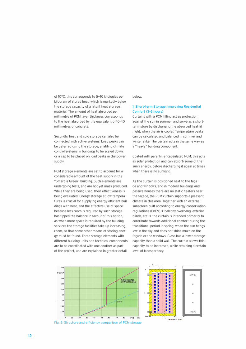
Fig. 8: Structure and efficiency comparison of PCM storage
Water
13
Another advantage of PCM curtains over PCM
walls is that they can hang freely, without being
cluttered up by furniture. The mass of the PCM
material applied to the curtain is very small com-
pared to solid or filled construction materials, so
it can be applied on both sides of the curtain or
corrugated (allowing approximately 1.5-2 times
the window surface). This can be covered directly
by the sun or the controlled ventilation, and
thus be fully charged and discharged. Tempe-
rature peaks can be balanced in this way, while
there is an increased feeling of comfort near the
windows.
The amount of PCM required for the curtains was
determined in laboratory tests carried out by the
company Outlast. The custom-built curtains were
imprinted on both sides with PCM. The white
base material, made of 100 per cent PES Trevira
CS (tested for harmful substances according
to Oeko-Tex Standard 100, weight approx. 200
grams per square metre), is printed in green on
one side, and then printed and surface-coated on
both sides in a dot pattern with a total of at least
130 grams per square metre of paraffin-bound
PCM.
During a two-year monitoring phase, the Techni-
cal University of Braunschweig will take mea-
surements near the curtains in order to assess
the results of their use. The impact of the users’
behaviour on the curtains’ efficiency and their
acceptance are to be reviewed.
The latent heat temporarily stored in the curtains
in the area surrounding the glass façades on
the south, east, and west sides of the building
enables higher levels of comfort to be achie-
ved around large window surfaces, while also
reducing radiative cooling. The larger window
surfaces on the south side, which have a greater
thermal intensity, allow more heat to be absorbed
over the course of the year. It should therefore be
possible to ensure both highly transparent faça-
des in residential buildings, and their acceptance
by the users.
2. Medium-Term Storage: PCMs as Central
Storage for Heat Supply
Excess solar thermal energy is stored in a buffer
tank (PCM tank). Using PCMs allows the volumes
handled by the tank to be halved in comparison
with conventional storage (see Figure 8). Energy
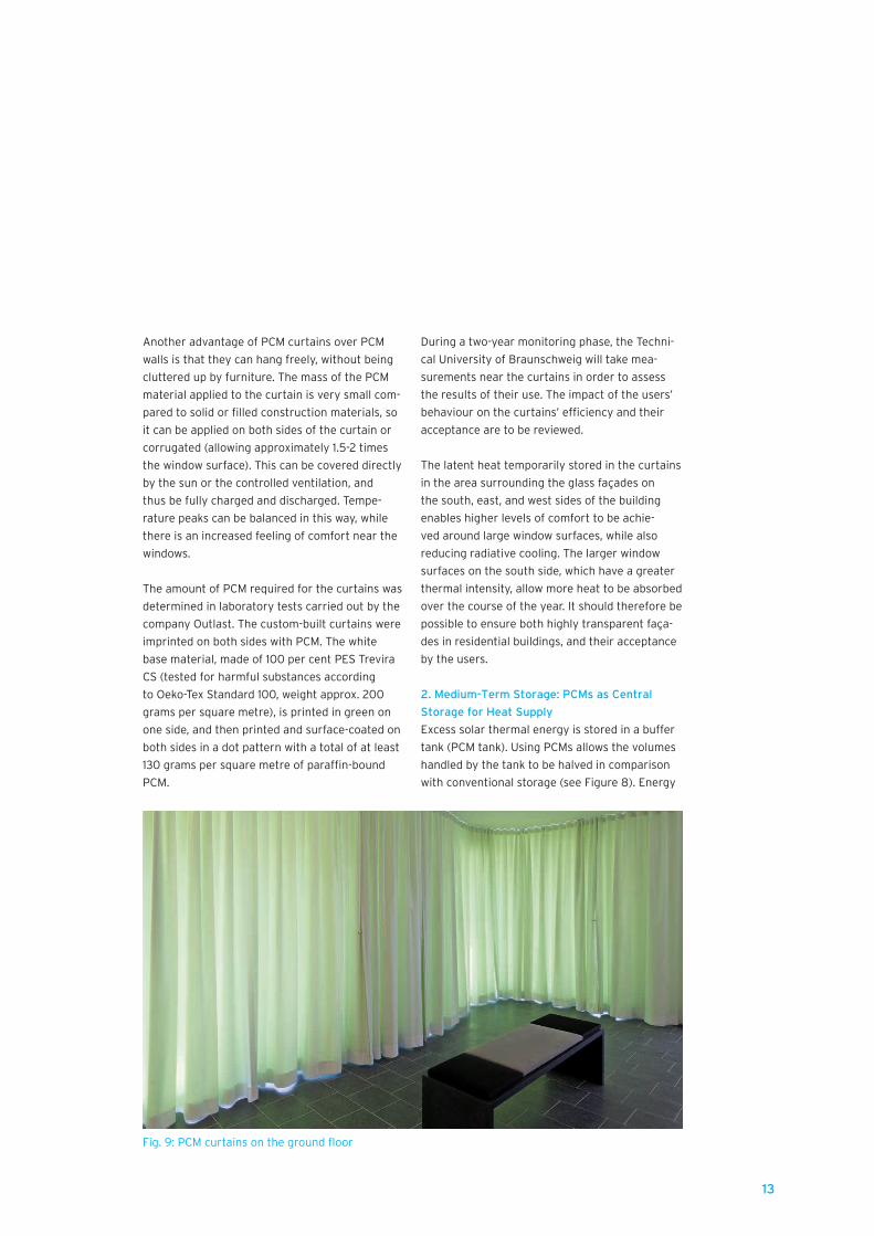
Fig. 9: PCM curtains on the ground floor

14
is stored at the temperature required for use in
underfloor heating; it is not necessary to mix
sources in order to achieve the desired flow
temperature. Further research should lead to in-
creased efficiency, with the aim of more efficient
heat transfer.
The solar thermal module is installed on the pa-
rapet wall and the flat roof in the form of vacuum
tube collectors. The collectors on the roof are
mounted at an angle of 15°. The collectors in the
parapet wall facility are mounted at 90° to the
parapet wall railings. This system generates an
output of approximately 75 kilowatts.
This produces a large amount of heat in the
summer months, which is stored in three hot
water tanks. Due to the high input temperature
generated by the solar thermal energy, the PCM
storage unit needs to be designed to cope with
such high temperatures. This prevents the solar
thermal system from coming to a standstill and
causing yield losses. The storage tank, manu-
factured by the company FSAVE, is designed
to withstand these high temperatures from the
solar thermal system, and can be adjusted to suit
the installation. The storage system – two hyd-
raulically connected storage tanks, each holding
a cubic metre – consists of reinforcing and highly
insulated plastic containers. The highly corrosi-
ve storage medium – a salt hydrate – precluded
metal from being used as the receptacle. The
material is therefore held by two cube-shaped
plastic containers.
Table 1: Dimensions of PCM storage (FLEXSAVE MONO PCM)
Outside measurements Length 1250 mm
Width 900 mm
Hight 2200 mm
Outside volume 2,475 m2
Interior Length 970 mm
Width 620 mm
Hight 1.940 mm Inside volume 1,167 m2
Bellow DN25 130 m
Surface 22,62 m2
Volume 83,72 dm3
Volume of girder 18,06 dm3
Filling volume 1,00 m3
Density of storage 159 kWh/m3
(20 – 90 °C)
Number of storages 2
Storage capacity overall system 319,53 kWh
Insulation PU foam
Tickness 120 mm
Termoconductivity 0,027 W/(m K)
Connecting Number 4 -
Measure 1 ''IG
Thermowell Number 5 -
Measure 1/2 ''IG
15
The generated heat energy is distributed to the
building services rooms and the heat storage
tanks for the three applications (water heating,
underfloor heating, district heating recovery
system) as required. The energy is distributed by
the in-house building management system. Most
of the generated heat energy is to be used within
the building for underfloor heating and water
heating.
The underfloor heating system is supplied with
heat energy by the PCM storage tank. This tank
is fed primarily by the solar thermal unit, and
can also be supplied by the local Wilhelmsburg
energy grid if required. Outside heating times,
the PCM storage tank preheats the cold drinking
water. The maximum operating temperature is
85°C.
Technically pure sodium acetate trihydrate with a
melting point of 58°C is used as the PCM materi-
al. This has a shelf life of over fifteen years. The
storage system consists of two cascade-connec-
ted tanks. This has the benefit that the smaller
storage tank does not require a stabilising outer
frame, which would reduce the storage volume.
The storage tanks have a usable total inner
volume of 2 cubic metres. The outer volume is
4.95 cubic metres. The storage capacity has an
average temperature of 60 kelvin (20-80°C) 280
kilowatt-hours . In comparison, water has a value
of 140 kilowatt-hours.
3. Long-Term Storage (Seasonal): Wilhelmsburg
Central Energy Grid
As the medium-term storage system is housed
within the building, excess heat can be fed into
the Wilhelmsburg Central energy grid and used
directly by other consumers or kept for the
future. If the apartment block’s stored heat is
discharged, any required heat can be obtained
from the local heat grid. In addition, the heat
from the PCM storage is transferred to a buffer
storage unit via a heat exchanger, and conveyed
from there to the handover station of the local
heat grid, or transferred the other way and remo-
ved from the local heat grid.
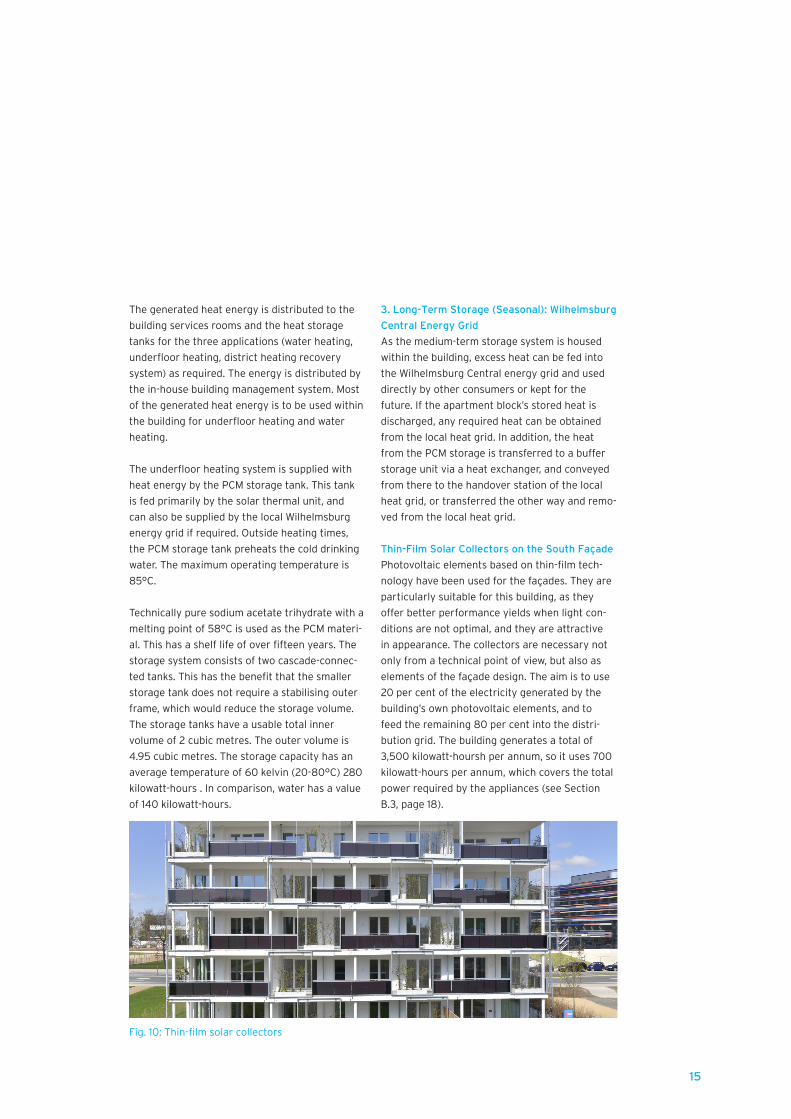
Thin-Film Solar Collectors on the South Façade
Photovoltaic elements based on thin-film tech-
nology have been used for the façades. They are
particularly suitable for this building, as they
offer better performance yields when light con-
ditions are not optimal, and they are attractive
in appearance. The collectors are necessary not
only from a technical point of view, but also as
elements of the façade design. The aim is to use
20 per cent of the electricity generated by the
building’s own photovoltaic elements, and to
feed the remaining 80 per cent into the distri-
bution grid. The building generates a total of
3,500 kilowatt-hoursh per annum, so it uses 700
kilowatt-hours per annum, which covers the total
power required by the appliances (see Section
B.3, page 18).
Fig. 10: Thin-film solar collectors

16
Building Management System
The close interaction between the technical
components for energy production and storage
means that good coordination is required. Energy
can be provided only in the same way as it is
in a conventional building, on demand from a
heat generator. This is only possible thanks to
sophisticated control systems engineering that
constantly monitors the possible energy sources
and consumers, and thus uses the energy as
effectively as possible. The special feature of this
system is not the technical performance of the
automated building components, but rather the
control concept. Central building automation is
required in order to adapt the different energy
generation components on the building’s outer
shell and the use of energy within the building
to one another in a smart way, and to increase
efficiency. Likewise, accessing energy from and
feeding it into the local heat grid is only possible
if the building is automated.
The block’s automated features are integrated
into a programmable, configurable building ma-
nagement system. This consists of one or several
digital-to-digital converter automation stations or
controllers, which undertake control, monitoring,
regulation, and management functions for the
following areas: heating technology, ventilation
(via meter only), and solar thermal energy. The
regulating system and control processes within
the appliances operate independently within
the respective automation stations or control-
lers. Important information is displayed next to
the appliances, on the power switch cabinets.
The override operating level is shown on the
control cabinet door (touch screen). Alarms and
malfunctions are displayed on the input modules.
Programs and other features can be accessed
via the integrated display or via a maintenance
and operator controlled laptop. This is connected
to the automation station or controller via an
attachment plug.
How the “Green” Curtain Works in Conjunction
with Heat Protection for the Building as Part of
the Façade
In addition to the photovoltaic elements contai-
ned in the railings, vertical gardens are integ-
rated into the façade in order to provide shade.
With climbing hydrangea on trellises, in summer
these offer leafy green curtains that provide
protection from the sun and filter solar radiati-
on. At the same time, this natural façade design
element absorbs carbon dioxide. The cooling
evaporation from the plants acts as a positive in-
fluence on the microclimate around the building.
The greenery of the vertical gardens serves as a
feature that changes with the seasons, and offers
seasonal protection against the sun: they are
closed against the summer sun, but remain open
for the winter sun. In construction terms, this is
a unitised system. The pre-grown climbing hyd-
rangeas are hooked onto the prefabricated tray
elements on the façade. The plants are watered
in the normal way, by rainwater, and are fed auto-
matically. With its design incorporating greenery,
photovoltaic elements, solar thermal energy,
and smart curtains, the south façade not only
showcases energy production, but also uses its
Fig. 11: Vacuum tube collectors on the parapet wall
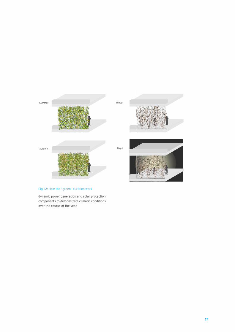
17
dynamic power generation and solar protection
components to demonstrate climatic conditions
over the course of the year.
Fig. 12: How the “green” curtains work
Summer
Autumn
Winter
Night

18
B.3 Building Services Concept
The building’s heat requirement, according to
Passive House guidelines, is roughly calcula-
ted at 19,250 kilowatt-hour per annum or 12
kilowatt-hour per square metre per annum. The
apartment block is primarily heated by the solar
thermal unit. The second source of heat, which is
used if there is not enough heat produced by the
building, is the Wilhelmsburg Central energy grid
district heat network. This heat is made available
by two PCM storage tanks that can hold 2 cubic
metres. The PCM storage tanks are operated as
latent heat stores using salt hydrate. The solar
energy produced by the solar thermal units (inte-
grated into the parapet wall area of the façades
and the roof surfaces) is fed into these storage
tanks. The solar units are integrated into the
parapet wall railings in the façade and on the re-
maining roof surfaces by vacuum pipe collectors
or flat-plate collectors.
The heat for the space heating is removed from
the PCM tank by a heat exchanger. The underf-
loor heating system is set up to provide system
temperatures of 35/25°C. If there is an excess of
solar energy, it is fed into the local heat grid. This
ensures that the heat supply is not interrupted in
long periods of cold, as it is provided by the local
heat grid. The building also receives renewable
energy from the local heat grid.
The building has a photovoltaic unit integrated
into the parapet wall railings on the south façade.
It is also possible to integrate photovoltaics
into the curtain elements on the east and west
façades. This would meet the goal of generating
all of the energy required by the block’s applian-
ces through the photovoltaic modules, providing
all of the domestic electricity, and, if necessary,
supplying two electric cars with charging current.
These supply options will allow the building to
achieve the status of a zero-energy house, which
means that almost all of the energy that it requi-
res is generated by itself.
The block also has a ventilation unit, and the
exhaust air from this is used to pre-heat the fresh
air. It is separate from the rest of the building
services. There is a separate ventilation unit for
each apartment. These supply the apartments
with the minimum hygienic air change. This form
of heat recovery has an efficiency of 91 per cent
for an electric power input for air conveyance of
0.31 watt-hour (very good Passive House stan-
dard). Additional air is not conditioned, except for
a defrosting function.
The building services concept is closely con-
nected to the extended transport concept. The
building concept was supplemented by a separate
local transport concept, with the result that the
Fig. 13: “Smart is Green” energy flow diagram
Solar energy collectors
Solar energy of collectors
Losses
Losses in pipes
Losses in storage
Solar energy of collectors
District heatingDistrict heating
Energy demand Amount of solar power

19
bicycle storage room on the ground floor has
charging stations for e-bikes. These are supplied
by the energy generated by the building itself.
There is also an on-site charging station for cars.
In addition, two electric cars are available and
can be used by any of the building’s residents.
This initiative was devised and funded by
SPARDA Bank and is a DENA model test in using
self-generated energy in-house and deploying car
batteries as storage for the energy produced.
Fig. 15: Building services operations room
Fig. 14: “Smart is Green” technology concept diagram
Schema TechnikkonzeptStand: 20.09.2012
H:\148 IBA Wohngebäude, Am Inselpark, HH-Wilhelmsburg (Neubau)\Zeichnung\Pinck\Visio\IBA Schema Technikkonzept.vsd Druckdatum: 20.09.2012/Jo
IBA Am Inselpark
PCM-Speicher
Fußbodenheizungca. 14.500 kWh/a
Solarthermieanlage
Wärmeüber-gabestation
Fernwärme-Einspeisung
ca. 33.000 kWh/a
Fernwärme-Rückspeisung
ca. 16.000 kWh/a
Warmwasserbereitungca. 35.500 kWh/aPhotovoltaik-
Fassadenanlage
Wechsel-richter
Strom-Rückspeisung
ca. 2.800 kWh/a
AnteiligeStromeigennutzung
ca. 700 kWh/a
Sommerfall
Winterfall
Sommerfall Winterfall
Produzierte Strommenge: ca. 3.500 kWh/a
Produzierte Wärmemenge:ca. 42.000 kWh/a
solar heating
PV in façade
Produced heat:
Hot waterapprox.
approx.
approx.approx.
approx. approx.approx.
Produced electricity approx.
summer
winter
PCM storage
inverterheat transfer
Summer: Abundance transfered to district heating
Winter: Purchased heat from district heating
self used electricity
Floor heating
Electricity transfered to mains

20
In the first phase of the three-stage competition
launched in mid-2009 a planning team composed
of architects, building technicians, and lands-
cape designers developed a concept that made
“energy harvesting and storage” the apartment
block’s main design principle. The ideas put for-
ward by the selected teams were refined during
the second stage. It was intended that all of the
walls and the roof would be able to harvest and
store energy (using photovoltaic collectors and
PCMs), and these features were integrated into
the design of the building as much as possible.
Parallel to this, a smart concept was developed
for the building’s internal design, which would
allow adaptable apartments.
several generations. The number of units on each
floor was also lowered from four to three in order
to ensure that two large apartments on each
floor could be divided, in the interests of greater
versatility.
Bringing the number of apartments on each floor
down from four to three allowed the staircase to
be placed adjacent to one of the exterior walls.
The apartments cover a larger area as a result,
making them more family-friendly. This made it
possible to situate a spacious and freely accessib-
le foyer and communal area at the entrance to
the building, without having to apply additional
fire safety measures.
The ground-floor commercial zone incorporated
in the original design also proved to be unfeasible
in terms of both building regulations and trade.
The play areas originally planned for the roof
were therefore integrated into the ground floor,
as greater upgrading of the solar thermal system
alongside the photovoltaic units was required to
B.4 Planning Process
Fig. 16: Image from the competition design
The third stage involved finding investors for the
concept that won the second phase. Behrendt
Wohnungsbau KG (GmbH+Co.) and Sparda
Immobilien GmbH were finally chosen. Construc-
tion work began in March 2013, once a number
of changes had been made to the competition
design. This progression from idea to detailed
design and, ultimately, the finished building, in-
volved mostly technical changes and, to a lesser
extent, architectural adjustments.
Due to the elimination of the height difference
on every second floor, the apartments can be
divided up in a flexible way, to allow for changes
within a generation cycle. All of the apartments
are now therefore accessible, although this was
not envisioned by the original design, which was
contrary to the aim of providing living space for
Fig. 17: Staircase in Smart is Green

21
safeguard the energy concept. Due to various
technical conditions and changes, spaces for
energy generation were reallocated during the pl-
anning stage. When the building services concept
was developed in conjunction with businesses,
the positioning of the solar thermal units within
the balcony railings was shown to be impractical.
The high cost of installation, due to the extensive
cable lengths, could not be squared with the desi-
red energy efficiency (line losses) and the design
requirements. In addition, the probable high
temperatures meant that there would be a risk
of injury in the open outdoor areas around the
building. The solar thermal system was therefore
replaced with photovoltaic units, which could be
simply integrated. These are now positioned bet-
ween the planted elements in the balcony areas
on the south, east, and west façades. The idea of
fitting all of the sun-facing façades with photo-
voltaic modules was not followed up for technical
reasons (the convection sizes of the modules)
and due to very limited efficiency coupled with
high costs. As a result, the intended generation
level of 7,000 kilowatt-hours per annum could not
be achieved: the current performance is 3,500
kilowatt-hours per annum. Thanks to progress in
technological development, especially in terms of
increased efficiency, the east and west façades
can be retrofitted with photovoltaic units.
As the roof surfaces were not large enough to
allow all of the building’s hot water and appliance
electricity needs to be met, the parapet wall was
added to the design. A solar thermal system in
the form of visually appealing pipe collectors is
located in the parapet wall area visible above the
balconies, and finishes off the roof surface.
The excess energy that cannot be fed into the
fully loaded PCM storage tanks is not stored in a
geothermal probe, as specified in the competition
design, but, rather, made available to the Wil-
helmsburg Central energy grid. In return, during
periods when the building is undersupplied with
its own energy, it receives heat from the energy
grid. It must be said that the solar thermal areas
are oversized for the building and its needs. By
connecting to the existing district heat network
the excess energy can be virtually cached and
bring the carbon balance sheet back to neutral.
The very latest technologies were planned for
“Smart is Green”, to support the aim of energy
generation. The integration of the photovoltaic
and solar thermal elements into the building’s
façades presented a challenge. The crisis in the
photovoltaics manufacturing market severely re-
stricted custom design options (convection sizes,
special sizes, module colour). No material could
be found in the field of PCM technology that
could be incorporated into a storage tank and
would also be suitable for a temperature range
around 40°C. A PCM that was suited to high tem-
peratures around 80°C was ultimately selected,
but it was difficult to find a manufacturer that
could offer the appropriate storage technolo-
gy, combining high temperatures and the high
corrosiveness of the salt hydrate. The solution
was found at the company FSave, whose activi-
ties were otherwise concentrated in the field of
energy and heat transport. FSave had sufficient
experience in creating plastic storage tanks for
use with salt hydrate and high temperatures.
Fig. 18: Building site, summer 2012

22
The PCM storage tanks caused particular prob-
lems, as there was a lack of suitable manufactu-
rers. The technology is still in its infancy; while
there is a great deal of research, not much of it
has been put into practice.
The project has led to increased information
about PCM storage on the part of the building
service engineers who worked on it. This tech-
nique was previously unfamiliar to them, but it
will now come into play on future projects. PCM
technology has been “all the rage” for some time,
but there were few practical examples in which
this material had been used for storage tanks. Up
until now, PCMs have been used in construction
materials for heat storage, but not as containers
that act as a substitute for water storage tanks.
As they can store twice as much heat as a water
tank, the PCM tanks have a crucial space-saving
advantage, as heat transfer is easier to achieve.
As the use of renewable forms of energy increa-
ses, the building services areas also must be able
to grow, particularly due to the need for energy
storage facilities, and PCM storage tanks require
much less room in comparison with conventional
storage units. The space left over can therefore
be put on the market. At present, as the sale
of the recovered areas fetches more than the
additional costs of building a PCM storage tank,
the use of this technology makes sense on a
large scale.
“Smart is Green” has made ample use of this
space advantage. It must be acknowledged that
many of the materials employed in the private
sector would not have been used to the same
extent for building projects that did not receive
funding. Often the costs were not commensurate
with the actual use, as the technologies show-
cased as part of the project – the PCMs or the
photovoltaic units on the walls – are not yet suf-
ficiently mature in technological terms to offer
reasonable payback periods. However, as “Smart
is Green”, as a model, is aimed at demonstrating
the possibilities of energy generation and storage
from various renewable sources, this does not
present any problems, as the project is focused
on gathering experience about the way in which
the materials interact, in order to make the struc-
tures used here suitable for mass production and
applicable to other types of buildings.
Not all of the ideas put forward in the competi-
tion were implemented regardless of their pro-
fitability, however Many of them were adjusted
for financial reasons, so that the energy concept
was changed from a plus energy house to a zero
energy house. There were also some difficulties
in executing the technology concept, as the va-
rious parties involved had a different understan-
ding of what the planned energy concept would
entail. In short, there was a lack of experience
in dealing with the materials used, and with the
completely renewable energy concept as a whole.
On an administrative and political level, there
is still a lack of knowledge about how to handle Fig. 19: First floor interior view
B.5 Assessment
Fig. 20: View from the west, May 2013

23
smart materials – the environment often does
not seem quite ready for the use of innovative
technology beyond conventional design.
The east and west façades are not ideal for
vertically placed photovoltaic units, as optimum
efficiency cannot be achieved. It was also impor-
tant to demonstrate the possibilities of integra-
ting photovoltaic modules into the building. Cost
is a particularly pertinent factor here – high-
quality photovoltaic elements with an attractive
appearance have a high price to match. Due to
the low level of efficiency, the payback period
corresponds to almost the entire building cycle.
Further research was required before photovol-
taic units could be used as an element of the
façade design. In order to increase the profitabi-
lity of the photovoltaic units on the façade, addi-
tional tweaks would have had to be made to the
architectural design, which proved impossible in
this case due to the location of the construction
site and other restrictions.
Increasing the supply of renewable energy in
the future means increasing the energy storage
facilities within the building. The technology for
this needs to be perfected, as in many cases it is
not yet really economically viable. The payback
periods are still too long. Yet there is no known
approach to the storage technology that would
enable PCMs to solve storage problems in the
absence of natural underground storage (e.g.
rock, stone) below the building. Due to various
constraints the building services room is quite
small, at only 20 square metres. Given the large
amount of space required by the use of solar
thermal energy (transfer station, collecting
buffer, expansion vessels), such a small space
was able to serve this function only by using PCM
technology.
With its holistic approach and use of e-mobility,
decentralised self-sufficiency, and connection
to a central heat supply, this apartment block
demonstrates how climate change can be
actively addressed in housing construction, so
that residential buildings no longer act as a drain
on energy, but as energy generators and stores
in their own right. Architecture and structural
engineering are used to join up function and
form, making versatile use of the space possible,
and the result acts as an example of construction
that will meet the requirements of inner-city
urban housing in the years to come.
Fig 22: View from first-floor balcony, May 2013Fig. 21: First floor interior

24
Cover:
Figure 1:
Figure 2:
Figure 3:
Figure 4:
Figure 5:
Figure 6:
Figure 7:
Figure 8:
Figure 9:
Figure 10:
Figure 11:
Figure 12:
Figure 13:
Figure 14:
Figure 15:
Figure 16:
Figure 17:
Figure 18:
Figure 19:
Figure 20:
Figure 21:
Figure 22:
Picture Credits
zillerplus Architekten und Stadtplaner, München
IBA Hamburg / Bernadette Grimmenstein
IBA Hamburg / Martin Kunze
zillerplus Architekten und Stadtplaner, München
zillerplus Architekten und Stadtplaner, München
zillerplus Architekten und Stadtplaner, München
IBA Hamburg / Martin Kunze
zillerplus Architekten und Stadtplaner, München
PINCK Ingenieure Consulting GmbH, Hamburg
zillerplus Architekten und Stadtplaner, München
IBA Hamburg / Martin Kunze
IBA Hamburg / Martin Kunze
Burger Landschaftsarchitekten, München
PINCK Ingenieure Consulting GmbH, Hamburg
PINCK Ingenieure Consulting GmbH, Hamburg
IBA Hamburg / Bernadette Grimmenstein
IBA Hamburg
zillerplus Architekten und Stadtplaner, München
IBA Hamburg / Martin Kunze
IBA Hamburg / Bernadette Grimmenstein
IBA Hamburg / Martin Kunze
IBA Hamburg / Bernadette Grimmenstein
IBA Hamburg / Bernadette Grimmenstein