august 2015 - rocky mountain measurement...
TRANSCRIPT

Fluid Flow Conditioning
August 2015

CPA Flow Conditioning 2015 August-24-15
Flow Conditioning
• There is no flow meter on the market that needs flow conditioning.
• All flow meters are effective without any type of flow conditioning.

CPA Flow Conditioning 2015 August-24-15
Flow Conditioning
Why do we want to use flow conditioners then?
• Can eliminate up to 80 – 90% of pipeline swirl. • Restore flow profile symmetry and eliminate distortions. • Isolates the flow meter from upstream disturbances. • Allows much shorter meter runs to be used with much higher repeatability. • Improves the benefits of many USM diagnostics by providing flow stability. • Helps with noise or pulsation problems. • Helps balance the pressure, velocity and flow rate of meter tubes running in
parallel.
• They UNLOAD the flow meter, helping it become even more accurate.
CPA Flow Conditioning 2015 August-24-15
Flow Conditioning
What if we have debris in our pipe? • The debris has to go somewhere, ignoring the flow conditioner won’t make it
disappear. • Install a filter (or another flow conditioner UPSTREAM of the meter run to catch
the debris). • Without something to catch debris, we risk damaging or destroying any sample
probes, thermo wells or any other equipment in the pipe. • Better hope there isn’t a compressor or turbine downstream somewhere. • If the gaskets are unraveling, recommend switching to Flexitallic CGI gaskets
with an inner ring to keep the windings intact.

CPA Flow Conditioning 2015 August-24-15
Flow Conditioning
• Using a flow meter without flow conditioning is simply giving up measurement accuracy and giving up money.
• Is our flow measurement ‘good enough’?
• Shouldn’t we aim for it to be the best, most accurate, lowest uncertainty measurement that is available with our current state of technology?

CPA Flow Conditioning 2015 August-24-15
What is a Flow Conditioner?

CPA Flow Conditioning 2015 August-24-15
What is a Flow Conditioner?

CPA Flow Conditioning 2015 August-24-15
What is a Flow Conditioner?

CPA Flow Conditioning 2015 August-24-15
What is a Flow Conditioner?

CPA Flow Conditioning 2015 August-24-15
Why should we use a Flow Conditioner?
When dealing with flow measurement, we cannot simply stick a flow meter in the pipe, turn it on and expect perfect results. In the real world, we have to deal with: • Installation effects • Swirl • Flow profile distortion • Pulsation • Noise
All of these combine in different ways to generate measurement errors!

CPA Flow Conditioning 2015 August-24-15
Fully Developed Flow
• Fully developed pipeline flow is the ideal state of a fluid in a pipe.
• If we had an infinitely long pipe, this is the flow we would always see.
• It is mathematically predictable.
• It is perfectly symmetrical around the center of the pipe.
• It has no swirl.
• This *should* guarantee us perfect, error free, repeatable measurement.
• Installation effects take us away from this state.

CPA Flow Conditioning 2015 August-24-15
Fully Developed Flow
0
0.2
0.4
0.6
0.8
1
1.2
1.4
1.6
0 0.05 0.1 0.15 0.2 0.25 0.3
Nor
mal
ized
Flo
w V
eloc
ity (V
/Vav
g)
Distance Across Pipe (m)
30000000 3000000 300000 30000 15000 10000 6000 1000 300

CPA Flow Conditioning 2015 August-24-15
Fully Developed Flow

CPA Flow Conditioning 2015 August-24-15
Swirl
• Swirl is the rotation of fluid in a pipe.
• It is caused by any change in piping direction!
• It can also be caused by any partial restriction of a pipe.

CPA Flow Conditioning 2015 August-24-15
Swirl

CPA Flow Conditioning 2015 August-24-15
Swirl

CPA Flow Conditioning 2015 August-24-15
Swirl

CPA Flow Conditioning 2015 August-24-15
Swirl

CPA Flow Conditioning 2015 August-24-15
Swirl
• Swirl causes unpredictable distortions in the flow profile that change over time.
• Swirl flattens and then inverts flow profiles due to centripetal force. The harder the fluid is spinning, the more energy that is pushed to the pipe walls.
• Swirl can cause local effects due to the location of pressure taps (dP measurement) or in the case of Ultrasonic Meters (adding to or subtracting to local path velocity).

CPA Flow Conditioning 2015 August-24-15
Installation Effects
Every pipe fitting generates an installation effect. • Tees • Elbows • Expanders • Reducers • Valves • Probes
All of these objects can combine to create a deviation from perfect fully developed flow.

CPA Flow Conditioning 2015 August-24-15
Installation Effects - Elbows

CPA Flow Conditioning 2015 August-24-15
Installation Effects - Tees
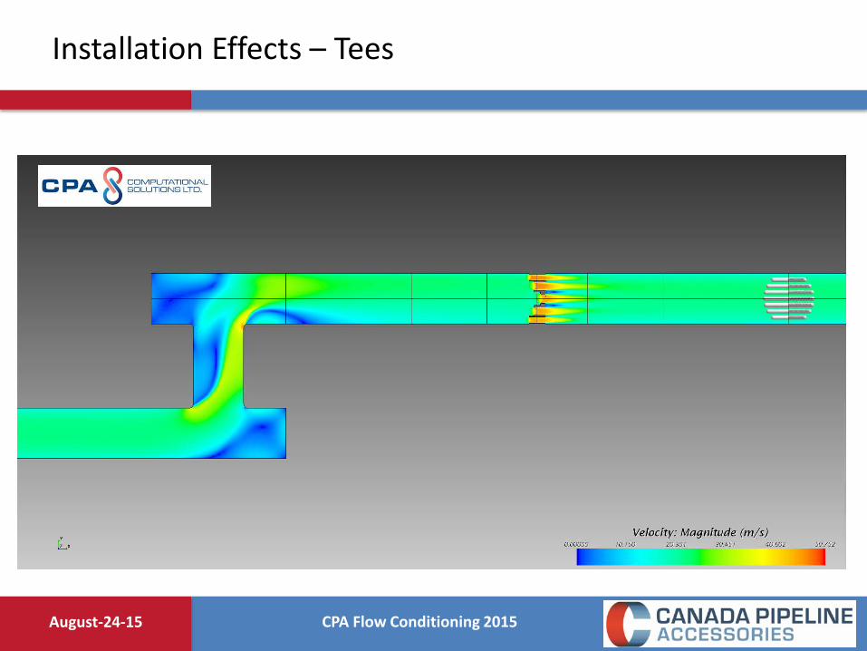
CPA Flow Conditioning 2015 August-24-15
Installation Effects – Tees
CPA Flow Conditioning 2015 August-24-15
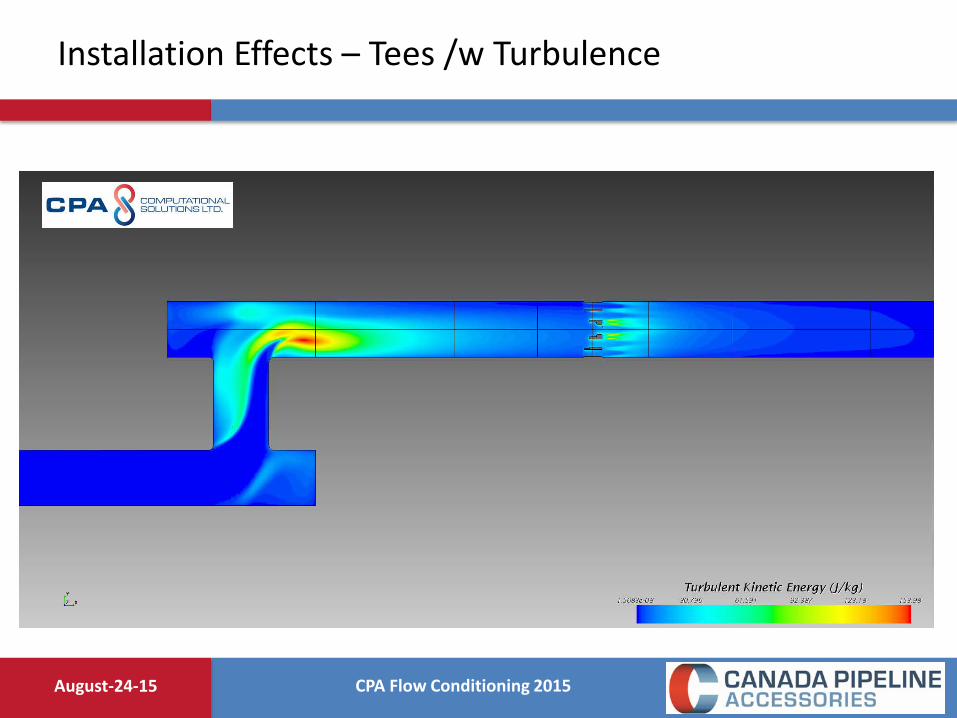
Installation Effects – Tees /w Turbulence
CPA Flow Conditioning 2015 August-24-15
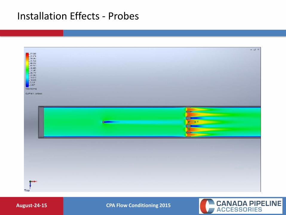
Installation Effects - Probes

CPA Flow Conditioning 2015 August-24-15
Installation Effects – Valves

CPA Flow Conditioning 2015 August-24-15
Installation Effects – Elbows & Orifice Plates

CPA Flow Conditioning 2015 August-24-15
Installation Effects – Reducers
CPA Flow Conditioning 2015 August-24-15
Measurement Errors
• The further we get from our perfect, swirl free, fully developed flow, the more uncertain our measurement becomes.
• Error due to flow profile distortion – deviation from baseline state.
• Error due to swirl itself.
• What if we want to shorten our meter run?
• What do we do?

CPA Flow Conditioning 2015 August-24-15
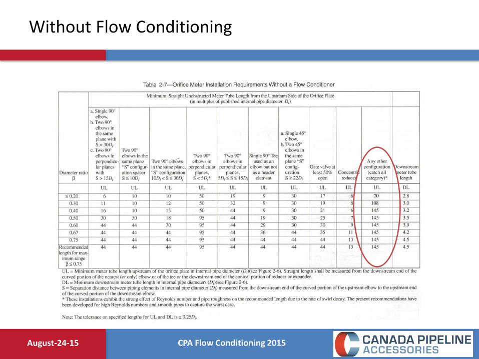
Without Flow Conditioning
• We can build a meter run without any sort of flow conditioning!
• It just needs to be very long to compensate for installation effects and swirl.
• AGA3-2000 even allows this.
• Table 2-7 shows suggested meter run lengths when a flow conditioner won’t be used…but the runs could end up being 44D, 95D or even up to 145D long!!

CPA Flow Conditioning 2015 August-24-15
Flow Conditioning
A properly designed Flow Conditioner converts this flow....
...Into this.

CPA Flow Conditioning 2015 August-24-15
Flow Conditioning
A properly designed Flow Conditioner converts this flow....
...Into this.
CPA Flow Conditioning 2015 August-24-15
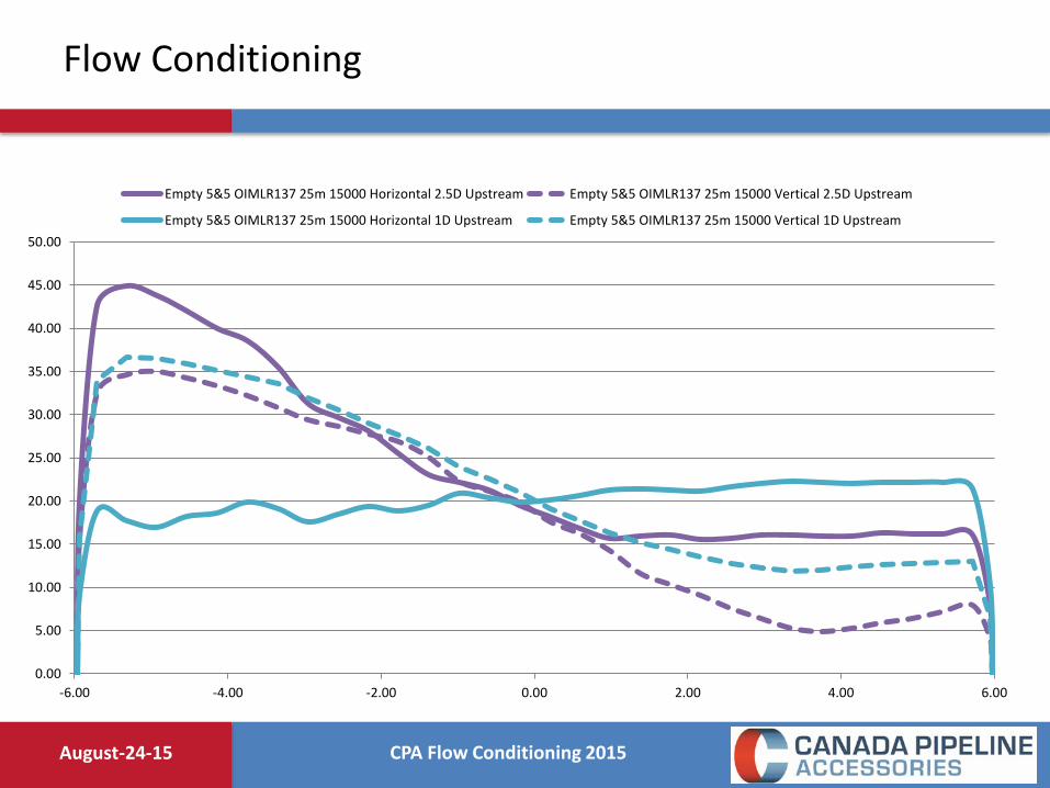
Flow Conditioning
0.00
5.00
10.00
15.00
20.00
25.00
30.00
35.00
40.00
45.00
50.00
-6.00 -4.00 -2.00 0.00 2.00 4.00 6.00
Empty 5&5 OIMLR137 25m 15000 Horizontal 2.5D Upstream Empty 5&5 OIMLR137 25m 15000 Vertical 2.5D Upstream
Empty 5&5 OIMLR137 25m 15000 Horizontal 1D Upstream Empty 5&5 OIMLR137 25m 15000 Vertical 1D Upstream

CPA Flow Conditioning 2015 August-24-15
Flow Conditioning
0.00
5.00
10.00
15.00
20.00
25.00
30.00
-6.00 -4.00 -2.00 0.00 2.00 4.00 6.00
CPA50E 10&10 OIMLR137 25m 11500 Horizontal 5D Downstream CPA50E 10&10 OIMLR137 25m 11500 Vertical 5D Downstream
CPA50E 10&10 OIMLR137 25m 11500 Horizontal 8D Downstream CPA50E 10&10 OIMLR137 25m 11500 Vertical 8D Downstream
CPA50E 10&10 OIMLR137 25m 11500 Horizontal 15D Downstream CPA50E 10&10 OIMLR137 25m 11500 Vertical 15D Downstream

CPA Flow Conditioning 2015 August-24-15
Elbows – Swirl Removal

CPA Flow Conditioning 2015 August-24-15
Tees – Swirl Removal

CPA Flow Conditioning 2015 August-24-15
Swirl – ALL SCENARIOS

CPA Flow Conditioning 2015 August-24-15
Flow Conditioner Swirl Reduction

CPA Flow Conditioning 2015 August-24-15
Meter Types
• All volumetric flow meters can be flow conditioned: Orifice, Ultrasonic, Venturi, Coriolis Vortex, Turbine, Cone, Mag, etc.
• Every meter type responds differently to the effects of swirl and flow profile
distortion.
• Volumetric flow meters are looking for ‘good flow’. Flow with minimal swirl and good flow profiles.
• A flow conditioner is simply trying to improve the flow that the meter is seeing.

CPA Flow Conditioning 2015 August-24-15
CPA once said….
• It’s far easier to measure good flow with a bad meter, than trying to measure bad flow with a good meter.

CPA Flow Conditioning 2015 August-24-15
Orifice Meters
• A thin plate with a very sharp chamfered hole creates a significant pressure drop.
• The flow rate of the fluid is proportional to the pressure drop.
• So why is there a problem?

CPA Flow Conditioning 2015 August-24-15
Orifice Meters

CPA Flow Conditioning 2015 August-24-15
Orifice Meters with Swirl

CPA Flow Conditioning 2015 August-24-15
Orifice Meters
Velocity Velocity Swirl P1 P2 Bulk Density K deltaP (fps) (m/s) (Degrees) (Pa) (Pa) (ρ) (Pa) 50 15.24 0 5598181 5458170 36.84 32.73 140011 50 15.24 20 5591067 5471339 36.74 28.06 119728 50 15.24 45 5560318 5497955 36.68 14.64 62363
• In orifice measurement, swirl can change the pressure differential that is being measured.
CPA Flow Conditioning 2015 August-24-15
Without Flow Conditioning

CPA Flow Conditioning 2015 August-24-15
Straight Pipe
From GRI 97/0207

CPA Flow Conditioning 2015 August-24-15
Straight Pipe – Elbows Out Of Plane
From GRI 97/0207

CPA Flow Conditioning 2015 August-24-15
Straight Pipe – 50% Closed Gate Valve
From GRI 97/0207
CPA Flow Conditioning 2015 August-24-15
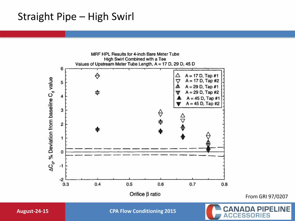
Straight Pipe – High Swirl
From GRI 97/0207

CPA Flow Conditioning 2015 August-24-15
Tube Bundles
From GRI 97/0207

CPA Flow Conditioning 2015 August-24-15
Tube Bundle Data

CPA Flow Conditioning 2015 August-24-15
Tube Bundles & Straightening Vanes
• Tube bundles can be very problematic in custody transfer applications.
• AGA3 test data has shown them to be have very unpredictable behavior in scenarios with various upstream configurations.
• A low pressure drop combined with a long length (2 – 3D) result in an inability to properly redistribute the flow profile, while locking in distortions.
• Testing has found tube bundles to cause errors in straight pipe baseline scenarios!
• AGA3 itself shows in table 2-8 that there are configurations where a tube bundles cannot even be used!

CPA Flow Conditioning 2015 August-24-15
17D with Tube Bundle
From AGA Report No. 3, 2000 Edition

CPA Flow Conditioning 2015 August-24-15
Plate Based Isolating Flow Conditioners
CPA Flow Conditioning 2015 August-24-15
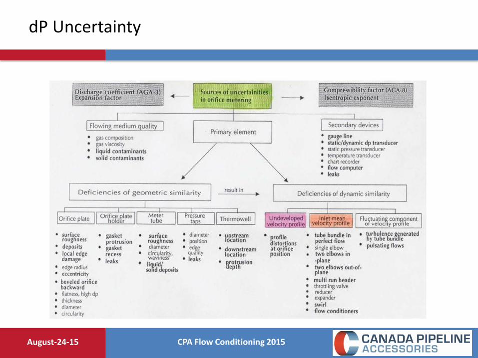
dP Uncertainty

CPA Flow Conditioning 2015 August-24-15
Cone Meters
• Similar to other dP devices.
• Have a high pressure and a low pressure tap.
• Has a unique geometry that forces flow to the outside of the pipe.
• High pressure tap is in a similar location as with a orifice plate or venturi, but low pressure tap is in the center of the element geometry.
• Supposed to be highly immune to installation effects and swirl, requires only 0 – 3 upstream pipe diameters and no flow conditioning.

CPA Flow Conditioning 2015 August-24-15
Cone Meters
• Similar to other dP devices.
• Have a high pressure and a low pressure tap.
• Has a unique geometry that forces flow to the outside of the pipe.
• High pressure tap is in a similar location as with a orifice plate or venturi, but low pressure tap is in the center of the element geometry.
• Supposed to be highly immune to installation effects and swirl, “requires” only 0 – 3 upstream pipe diameters and no flow conditioning.

CPA Flow Conditioning 2015 August-24-15
Cone Meters

CPA Flow Conditioning 2015 August-24-15
Cone Meters

CPA Flow Conditioning 2015 August-24-15
Cone Meters, with Upstream Disturbances

CPA Flow Conditioning 2015 August-24-15
Cone Meters, with Upstream Disturbances

CPA Flow Conditioning 2015 August-24-15
Cone Meters, with Swirl
CPA Flow Conditioning 2015 August-24-15
Cone Meters
• Do cone meters need flow conditioner and a minimum amount of upstream pipe?
• Tees upstream, 13D of straight pipe, 0.6b, ~0.5% deviation from baseline.
• 30 degrees of swirl, 13D of straight pipe, 0.6b, ~4.6% deviation from baseline.

CPA Flow Conditioning 2015 August-24-15
Turbine Meters
• Fluid rotation in the direction of the meter rotation causes the meter to under register.
• Fluid rotation in the opposite direction of the meter rotation causes the meter to over register.
• Dual rotor designs are less susceptible to this.
• Often, turbine meters will have straightening vanes in the inlet in an basic attempt at flow conditioning.

CPA Flow Conditioning 2015 August-24-15
Turbine Meters
• Turbine meters with nose cones redirect flow towards the outside of the fluid passage.
• This movement amplifies disturbances within the flow profile
• Turbine meters need to see a well flow conditioned bulk fluid flow.
• Asymmetrical or peaky flow profiles will cause the turbine to over register.

CPA Flow Conditioning 2015 August-24-15
Turbine Meters

CPA Flow Conditioning 2015 August-24-15
Turbine Meters

CPA Flow Conditioning 2015 August-24-15
Turbine Meters

CPA Flow Conditioning 2015 August-24-15
Turbine Meters

CPA Flow Conditioning 2015 August-24-15
Turbine Meters

CPA Flow Conditioning 2015 August-24-15
Turbine Meters

CPA Flow Conditioning 2015 August-24-15
Ultrasonic Meters
• Rely on a noise pulse that is transmitted through the fluid and the flow rate is computed using the transit time.
• Transit time is affected by velocity disturbances within the pipe, slowing or speeding up the pulse.
• Multiple paths help to generate a complete picture of the cross sectional flow within the pipe.
• The meter only knows how long it took for the pulse to travel from point A to point B.
• It cannot guess the state of the flow along the way.

CPA Flow Conditioning 2015 August-24-15
Ultrasonic Meters

CPA Flow Conditioning 2015 August-24-15
Ultrasonic Meters

CPA Flow Conditioning 2015 August-24-15
Ultrasonic Meters

CPA Flow Conditioning 2015 August-24-15
Ultrasonic Meters – 4 Path Data

CPA Flow Conditioning 2015 August-24-15
USM Results

CPA Flow Conditioning 2015 August-24-15
USM Path Layouts

CPA Flow Conditioning 2015 August-24-15
Flow Conditioning Swirl Removal

CPA Flow Conditioning 2015 August-24-15
Flow Conditioning Swirl Removal

CPA Flow Conditioning 2015 August-24-15
Pressure Drop
• All fittings, obstructions, even pipe itself has a “k factor”.
• The k factor is the pressure loss coefficient for a particular piece of piping.
• It is experimentally determined using the measured pressure drop.
• K = Pressure loss coefficient. • ΔP = Pressure drop across a section of pipe or a fitting. • ρ = Bulk fluid density, kg/m3. • V = Bulk fluid velocity, m/s.
2
2VkP ρ=∆
CPA Flow Conditioning 2015 August-24-15
Pressure Drop
• For natural gas applications, most plate flow conditioners have a K factor of approximately 2.
• Tube bundles are closer to 0.75 – 1.5.
• What if we are worried about the pressure drop across the flow conditioner?

CPA Flow Conditioning 2015 August-24-15
Relative Pressure Drop

CPA Flow Conditioning 2015 August-24-15
0.000
2.000
4.000
6.000
8.000
10.000
12.000
14.000
16.000
18.000
20.000
1 10 100 1,000 10,000 100,000 1,000,000 10,000,000 100,000,000
Pres
sure
Los
s Co
effic
ient
/ K
Fac
tor
Reynolds Number
Pressure Loss Coefficient vs Reynolds Number (Viscosity)
CPA 50E AGA 3 19-Tube Bundle
Pressure Drop – Tube Bundle vs Plate FC

CPA Flow Conditioning 2015 August-24-15
AGA Standards/Meter Run Compliance
• AGA 3 / API 14.3 - Orifice Meter Measurement • AGA 7 – Turbine Meter Measurement
• AGA 9 – Ultrasonic Meter Measurement
• AGA 11 – Coriolis Meter Measurement

CPA Flow Conditioning 2015 August-24-15
AGA3 Data

CPA Flow Conditioning 2015 August-24-15
AGA9/OIML R137 Data

CPA Flow Conditioning 2015 August-24-15
Flow Conditioning Conclusion
• Can eliminate up to 80 – 90% of pipeline swirl.
• Help restore flow profile symmetry and eliminate distortions.
• Isolates the flow meter from upstream disturbances.
• Allows much shorter meter runs to be used with much higher repeatability.
• Are applicable for all liquid or gas flows!
The flow conditioner is merely helping out the meter, providing higher reproducibility and lower uncertainty!
CPA Flow Conditioning 2015 August-24-15
Liquids/Pressure Drop Summary
• All fluid flows will benefit from flow conditioning.
• Flow measurement and flow conditioning in liquids is effectively the same as in gases.
• While we do need to be concerned about pressure drop, we have to look at the big picture; The flow conditioner will not be the most significant obstruction in the pipe.
• When dealing with pressure drop, previous common sense assumptions may not apply. Pressure loses through fittings can be complicated depending on the application.
• In some installations, pressure drop is very helpful. It helps balance meter tubes when multiple runs are used in parallel. Otherwise, severe run hogging and meter run imbalances may be experienced.

CPA Flow Conditioning 2015 August-24-15
Final Thoughts
• Swirl is primarily a function of piping geometry (the size and radius of the piping turns are critical for generating the swirl vector).
• Our attempts to make piping assemblies more compact result in tighter fittings that have a higher chance to produce severe turbulence and dynamic effects (vortex shedding, harmonics).
• Steady state installation effects (flow profiles and swirl) are complex enough, most dynamic behaviors are not well understood and aren’t well discussed within corresponding measurement guidelines and standards.
• Try to avoid tight radius tees whenever possible.

CPA Flow Conditioning 2015 August-24-15
Final Thoughts
• Even with the addition of more paths, the addition of a flow conditioner vastly adds to the repeatability and accuracy of a ultrasonic flow meter.
• The flow conditioner can easily cut the errors in half, and in some instances reduce the error by 90%!
• Sometimes we can get lucky and have acceptable performance without a flow conditioner. With measurement repeatability, we need to look at the bigger picture and the general trend of reducing our uncertainty.

CPA Flow Conditioning 2015 August-24-15
Final Thoughts
• The flow conditioner is just making the meter look better.
• Worried about pressure drop? Flow conditioners typically are the lowest dP fitting in a meter run assembly (ie, the accumulation of tees will quickly eclipse the dP of the plate).
• Flow conditioners are recommended for all FLUID applications (liquids and gas)!

CPA Flow Conditioning 2015 August-24-15
Final Thoughts
• Worried about debris plugging up the flow conditioner?
• If there is that much debris in the pipe line, a strainer or filter is heavily recommended.
• Eliminating the flow conditioner will not eliminate the debris, and now you’re at risk of breaking off probes and thermowells, damaging control & safety valves, turbines, compressors, etc.
• If the gasket is unraveling, switch to a CGI style gasket with a inner ring. The gasket unraveling is going to create bigger problems than just a plugged flow conditioner (plugged control valves and potential for leaking flanges).

CPA Flow Conditioning 2015 August-24-15
Thank You
• For Further information
www.flowconditioner.com www.cpacfd.com Danny Sawchuk Vice President, Sales & Engineering [email protected] 403.236.4480 403.620.7293