austempered gears and shafts-tough solutions · pdf fileaustempered irons austempering can be...
TRANSCRIPT
03 January 2001
Austempered Gears and Shafts: Tough Solutions
Kristin Brandenberg Kathy L. Hayrynen, PhD
John R. Keough, PE Applied Process Inc. Technologies Div.- Livonia, Michigan, USA
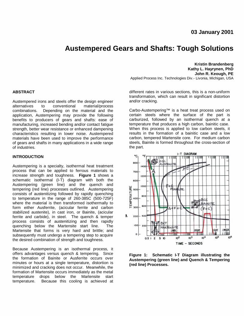
ABSTRACT Austempered irons and steels offer the design engineer alternatives to conventional material/process combinations. Depending on the material and the application, Austempering may provide the following benefits to producers of gears and shafts: ease of manufacturing, increased bending and/or contact fatigue strength, better wear resistance or enhanced dampening characteristics resulting in lower noise. Austempered materials have been used to improve the performance of gears and shafts in many applications in a wide range of industries. INTRODUCTION Austempering is a specialty, isothermal heat treatment process that can be applied to ferrous materials to increase strength and toughness. Figure 1 shows a schematic isothermal (I-T) diagram with both the Austempering (green line) and the quench and tempering (red line) processes outlined. Austempering consists of austenitizing followed by rapidly quenching to temperature in the range of 260-385C (500-725F) where the material is then transformed isothermally to form either Ausferrite, (acicular ferrite and carbon stabilized austenite), in cast iron, or Bainite, (acicular ferrite and carbide), in steel. The quench & temper process consists of austenitizing and then rapidly quenching below the Martensite start line. The Martensite that forms is very hard and brittle; and subsequently must undergo a tempering step to acquire the desired combination of strength and toughness. Because Austempering is an isothermal process, it offers advantages versus quench & tempering. Since the formation of Bainite or Ausferrite occurs over minutes or hours at a single temperature, distortion is minimized and cracking does not occur. Meanwhile, the formation of Martensite occurs immediately as the metal temperature drops below the Martensite start temperature. Because this cooling is achieved at
different rates in various sections, this is a non-uniform transformation, which can result in significant distortion and/or cracking. Carbo-Austempering™ is a heat treat process used on certain steels where the surface of the part is carburized, followed by an isothermal quench at a temperature that produces a high carbon, bainitic case. When this process is applied to low carbon steels, it results in the formation of a bainitic case and a low carbon, tempered Martensite core. For medium carbon steels, Bainite is formed throughout the cross-section of the part.
Figure 1: Schematic I-T Diagram illustrating the Austempering (green line) and Quench & Tempering (red line) Processes.
Ms

AUSTEMPERED IRONS Austempering can be applied to ductile and gray iron castings to produce beneficial properties relevant to numerous applications. In the case of gears and shafts, Austempering yields Austempered Ductile Irons (ADI) and Austempered Gray Irons (AGI) with better strength, wear resistance, and noise dampening properties than either as-cast irons or other competitive materials. As seen in Figure 2, the tensile and yield strength of ADI increases with increased Brinell hardness. The different grades of ADI, (achieved through a variation in the Austempering temperature and time), can create a range of properties in ADI applicable to the specific requirements of the component design, as seen in Table 1.
Figure 2 : Typical Properties of Austempered Ductile Iron as a function of Brinell Hardness.
Table 1 : ASTM 897 Property table for ADI
Grade Tensile
Strength (MPa/Ksi)
Yield Strength (MPa/Ksi)
Elong. (%)
Impact Energy (J/lb-ft)
Typical Hardness
(BHN)
1 850 / 125 550 / 80 10 100 / 75 269 – 321
2 1050 / 150 700 / 100 7 80 / 60 302 – 363
3 1200 / 175 850 / 125 4 60 / 45 341 – 444
4 1400 / 200 1100 / 155 1 35 / 25 366 – 477
5 1600 / 230 1300 / 185 N/A N/A 444 - 555
Figure 3 shows the relationship of as-cast gray iron to AGI as a function of austempering temperature. Increased tensile strength can be achieved by austempering gray iron at various temperatures.
Figure 3 : Tensile Strengths of Austempered Gray Iron as a Function of Austempering Temperature (F) CONTACT FATIGUE - Austempered Ductile Iron lends itself to increased contact fatigue strength and wear resistance. Figure 4 Compares the allowable contact stress behavior of ASTM Grades 2 and 5, (ASTM 1050-700-07 and 1600-1300-00).
Figure 4 : Contact Fatigue (90% Confidence Limits) From the ASME Gear Research Institute Figure 5 demonstrates that the contact fatigue properties of various grades of ADI are comparable to gas nitrided steels and competitive with carburized and hardened steel.

Figure 5 : Comparison of Contact Fatigue Strengths of ADI with Those of Conventional Ductile Iron and Steels Used for Gear Applications Figure 6 illustrates that ADI has improved abrasion resistance when compared to steels and quench and tempered ductile iron. ADI experiences less volume loss at similar hardness levels, resulting in a component with improved wear characteristics.
Figure 6 : Pin Abrasion Test, Comparing Volume Loss at Equivalent Hardnesses.4
BENDING FATIGUE – ADI also presents an increase in bending fatigue for gear applications. Figure 7 shows the comparative allowable tooth root bending stresses for ADI Grades 2 and 5.
Figure 7 : Single Tooth Bending Fatigue (90% Confidence Limits) From ASME Gear research Institute. Figure 8 shows a comparison of tooth root bending fatigue in various materials. This figure demonstrates that ADI is competitive with cast and through-hardened steels. It also shows that shot-peened ADI has improved fatigue strength that is comparable to gas-nitrided and case-carburized steels. Shot peening can improve the allowable bending fatigue of carburized and hardened steels by 30%, while it increases the allowable bending fatigue of ADI by 75%.
Figure 8 : Comparison of Bending-Fatigue Strength of ADI with Those of Conventional Ductile Iron and Steels Used for Gear Applications.

Radial Distance (inches)
0.000 0.005 0.010 0.015 0.020 0.025 0.030
Com
pres
sive
Str
ess
(ksi
)
0
20
40
60
80
100
120
140
160
180
200
UnpeenedS330, 24A
S230, 16-18A Plus S550, 18A
S170, 7-9AS330, 16-18A Plus S70, 4-6A
Unpeened
Figure 9 : Effect of Various Shot Peening Schemes on the Compressive Stresses of Grade 4 (ASTM 1400-1100-01) ADI. The bending performance of ADI can be greatly enhanced by shot peening and fillet rolling. In Figure 9, several shot peening combinations are measured for their affect on residual compressive stresses. The as-Austempered surface compressive stress observed was less than 30 ksi while the maximum shot peened surface compression was more than 130ksi. NOISE REDUCTION - ADI and AGI are not only competitive in bending and contact fatigue, but they also can greatly reduce the noise found in gears made of other materials. ADI can reduce the noise by over 2db compared to carburized and hardened 8620 steel gears6.
1 2 3 4 5 6 7 8 9 10 11 12 13 14 15
AGMA Class
Noi
se
.
Steel
Ductile Iron
Gray Iron
Figure 10 : Relative Comparison of Noise Reduction as a Function of Material and AGMA Class (courtesy of Wells Manufacturing, Dura-Bar Division)
As seen in Figure 10, gray iron and ductile iron are quieter than steel. This is due to the presence of graphite in ductile and gray iron, as well as the ausferrite matrix in Austempered Irons. The graphite nodules in ductile iron and the graphite flakes in gray iron create a dampening effect that significantly reduces the vibration in these materials. This allows for the possibility that gears machined to lower AGMA classes could be as quiet as those machined to more precise grades. Figure 11 schematically shows the relative dampening characteristics of steel as compared to ductile and gray iron.
Figure 11 : Vibration Characteristics of Gray Iron, Ductile Iron and Steel (courtesy of Wells Manufacturing, Dura-Bar Division)
Figure 12 : Comparison of Noise in Hypoid Gears During Vehicle Road Tests, from the ASME Gear Research Institute Report A4001.

A study done on a hypoid gear set, shown in Figure 12, compares the noise of this gear set when using steel, ADI or a combination of both materials. Note the improvement in noise level when both the ring gear and pinion are made of ADI.
Figure 13 : Damping of Austempered Gray Iron Compared to AS-Cast. The Austempering of gray iron also increases the noise reduction capabilities of gray iron. As seen in Figure 13 the damping characteristics of gray iron are increased when Austempered, giving the higher strength AGI better noise reduction characteristics than its as-cast counterparts. In fact, an AGI with a tensile strength of nearly 60 ksi can have the noise dampening capabilities of a fully damped, Class 20 Gray Iron. MANUFACTURABILITY – ADI and AGI offer an opportunity for increased manufacturability of a part. Rough machining can be done prior to heat treatment. In the as-cast condition, the material is much easier to machine, resulting in a lower cost to manufacture. Though many applications can be heat treated after final machining, finish machining after heat treatment increases the strength characteristics of ADI and AGI, giving them superior fatigue strength than prior to finish machining. Figure 14 compares the relative machinability of several ferrous materials. Note that ductile iron in a ferritic or pearlitic condition is easier to machine than 4140 steel or ADI. If ductile iron is machined prior to heat treatment, one can gain the advantage of better machinability. Furthermore, machining of ductile iron, gray iron, ADI and AGI results in a compact, discontinuous chip that is easily handled and is fully recyclable. Dry machining techniques can be easily applied to as-cast gray and ductile irons. This increased ease of manufacturabilty related to cast irons goes beyond improved machinability. Iron castings are generally nearer net shape and less expensive than steel forgings and castings. Figure 15 shows a comparison of relative material cost of different materials per unit of yield strength. Taking in to account all material and processing costs, ADI and AGI are
relatively less expensive to manufacture than other commonly used materials.
Figure 14 : Relative Machinability of Several Ferrous Materials Another benefit of austempering is reduced distortion and the elimination of quench cracking. When General Motors switched to ADI hypoid differential gears from the traditional Carburized and Hardened 8620 steel process in the 1970’s, they were able to eliminate the need for press quenching.
0
2
4
6
8
10
FORGEDALUMINUM
CASTALUMINUM
CAST STEEL FORGEDSTEEL
HEATTREATED
STEEL
DUCTILEIRON
ADI
Figure 15: Cost per Unit of Yield Strength of Various Materials APPLICATIONS OF ADI AND AGI GEARS As previously shown, ADI and AGI gears have higher bending and contact fatigue strengths, improved wear resistance and reduced noise levels. Figure 16 is an example of a hypoid gear set that realized a reduction in noise when switched from a steel application to ADI.
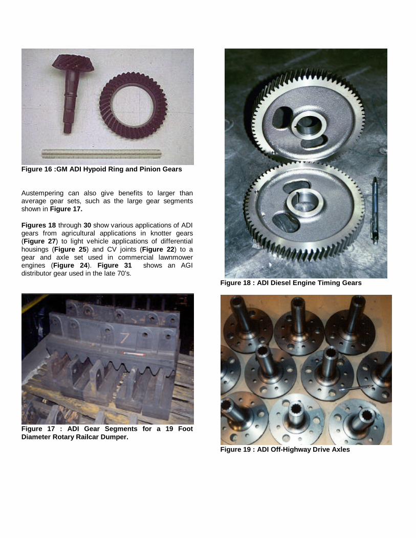
Figure 16 :GM ADI Hypoid Ring and Pinion Gears Austempering can also give benefits to larger than average gear sets, such as the large gear segments shown in Figure 17. Figures 18 through 30 show various applications of ADI gears from agricultural applications in knotter gears (Figure 27) to light vehicle applications of differential housings (Figure 25) and CV joints (Figure 22) to a gear and axle set used in commercial lawnmower engines (Figure 24). Figure 31 shows an AGI distributor gear used in the late 70’s.
Figure 17 : ADI Gear Segments for a 19 Foot Diameter Rotary Railcar Dumper.
Figure 18 : ADI Diesel Engine Timing Gears
Figure 19 : ADI Off-Highway Drive Axles

Figure 20: ADI Grade 1 Axle Hub Ring Gears.
Figure 21 : ADI Trailer Jackstand Pinions with As-Cast Teeth
Figure 22: ADI Inboard Constant Velocity Joint for Light Vehicles (Courtesy of Delphi)
Figure 23: Grade 1 ADI Internal Tooth Gear Wheel, 50 – 250 kg for Industrial Gear Reducer
Figure 24 : ADI Gear and Axle for Commercial Lawnmowers.
Figure 25 : ADI Limited Slip Differential Gear Housing

Figure 26 : ADI Grade 4 Scissor Lift Gear Housing
Figure 27: ADI Hay Baler Knotter Gear
Figure 28 : ADI Conduit Bender Gear
Figure 29 : ADI Planetary Gear Wheel Hub for Tractor Axles
Figure 30 : ADI Sprockets for Crawler Type Construction and Agriculture Equipment

Figure 31: AGI Gear for Timing on a Light Vehicle Engine AUSTEMPERED STEELS Medium and high carbon steels can be successfully Austempered along with powdered metal mixes that have sufficient hardenability and nearly full density. In general, the steel that is selected must have a TTT diagram that exhibits the following characteristics:
1. A pearlite start time (nose) that is sufficiently delayed to avoid its formation on quenching to the Austempering temperature.
2. A reasonable Bainite transformation time. 3. A Martensite Start Temperature (Ms) that is low
enough to allow for the formation of Bainite. Austempered steel offers several advantages when compared to conventional quench & tempered steels. Because Austempered steel is formed by an isothermal transformation, the likelihood of distortion is reduced and the presence of quench cracks is eliminated. The bainitic microstructure produced by Austempering is more wear resistant than tempered Martensite as illustrated in the pin abrasion test results of Figure 6. In addition, bainitic steels are more resistant to hydrogen embrittlement and stress corrosion cracking. For example, at high hardness levels (>38 Rc), Martensitic bolts are subject to stress corrosion cracking. Austempered bolts do not exhibit this behavior. For given high hardness levels (Rc > 40), Austempered parts exhibit higher strength and toughness than comparable quench & tempered parts as shown in Table 2.
Table 2: Gross and Bain Comparative Data for 0.74% C Steel Parts7
Quench & Tempered Austempered
Rc Hardness 50 50
UTS (MPa / ksi) 1701 / 246.7 1949 / 282.7
Yield Strength (MPa / ksi) 839 / 121.7 1043 / 151.3
Elongation (% in 6 inches) 0.3 1.9
%RA 0.7 34.5
Impact* (J / ft-lbs) 3.9 / 2.9 47.9 / 35.3
Above a certain hardness level, the fatigue strength of conventional quench & tempered steel drops significantly as illustrated in Figure 32. This does not occur in Austempered structures. In fact, the fatigue strength continues to increase up to the maximum bainitic hardness.
Figure 32 : Fatigue Strength of Bainite vs. Tempered Martensite AUSTEMPERED STEEL APPLICATIONS There are numerous applications of austempered gears as shown in Figures 33 - 35. They vary in section size from the 1 mm thick wave plates pictured in Figure 33 to the large gear segments shown in Figure 35.

Powdered metal steel parts of sufficient density can also be austempered. Examples include the metal sprag races shown in Figure 36. Austempered steel applications are not limited to gears. Output shafts as pictured in Figure 37 are Austempered for high strength and toughness with low distortion.
Figure 33 : Austempered Steel Wave Plates
Figure 34 : Austempered Steel Transmission Gears.
Figure 35: Austempered Steel Large Gear Segments
Figure 36 : Austempered Steel, Powdered Metal Sprag Races
Figure 37: Austempered Steel Output Shafts CARBO-AUSTEMPERED™ STEEL Low to medium carbon steels are good candidates for Carbo-Austempering™ . Typically a high carbon, bainitic case (Rc 50 to 60) is produced on a component with a lower carbon, tempered Martensite core (Rc < 40). In some instances, advantages have been realized in medium carbon alloy steels with a high carbon, bainitic case (45-55 Rc) on a medium carbon, bainitic core (45-50 Rc). Carbo-Austempering™ , like Austempering, is a low distortion heat treatment process when compared to conventional carburize quench and temper heat treatments. During Carbo-Austempering™ , the transformation begins in the center or core of the part. This results in the formation of compressive stresses as the outside layer or case transforms last during the heat treat process. The residual compressive stresses on the surface of a Carbo-Austempered™ steel result in improved high load, low cycle fatigue properties versus conventional Carburized and Hardened steel. This is

illustrated in Figure 38, which contains rotating bending fatigue curves for both Carbo-Austempered™ and conventionally carburized and hardened 8822 steel. Note the superior performance of the Carbo-Austempered™ steel in the low cycle regime (<105 cycles).
Figure 38: Rotating Bending Fatigue Properties of Carbo-Austempered? vs. Conventionally Carburized and Hardened 8822 Steel. Similar results were obtained with single tooth bending fatigue testing of Carbo-Austempered™ 8620 steel. This is illustrated in Figure 39, which contains single tooth gear fatigue curves for 8620 steel that has been both Carbo-Austempered™ and carburized, quenched and tempered. The Carbo-Austempered™ gears will carry loads up to 40% greater than their Carburized Q&T counterparts in the low cycle regime. Additionally, the Carbo-Austempered™ gears have an endurance limit that is 17% greater than the Carburized Q&T gears
Figure 39 : Load versus Cycles to Failure for Carbo-Austempered™ and Carburized, Quench and Tempered 8620 Steel Gears.
Carbo-Austempered steels also exhibit superior toughness or impact properties in comparision to conventional Carburized and Hardened steel. Figures 40 and 41 illustrate such a comparison for both v-notched and unnotched impact specimens from 5120 steel, respectively. The notched impact energy of the Carbo-Austempered™ specimens is almost twice that of the Carburized and Hardened specimens in Figure 40. The difference in performance for the unnotched bars is significantly higher with the Carbo-Austempered™ impact energy being in excess of twenty-two times that of the Carburized and Hardened 5120 shown in Figure 41.
Figure 40 : A Comparison of Ffatigue Strength of V-notched Carbo-Austempered™ and Carburized and Hardened Steel of Similar Hardness.
Figure 41 : A Comparison of Fatigue Strength of Unnotched Carbo-Austempered™ and Carburized and Hardened Steel of Similar Hardness.
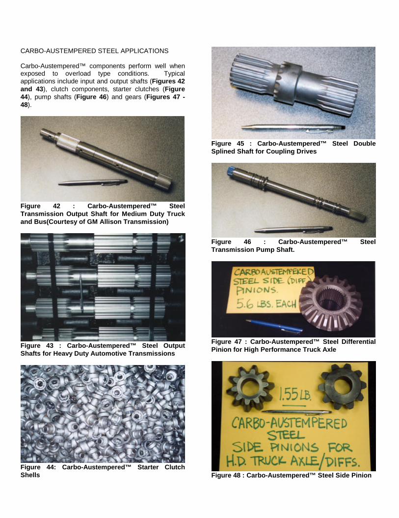
CARBO-AUSTEMPERED STEEL APPLICATIONS Carbo-Austempered™ components perform well when exposed to overload type conditions. Typical applications include input and output shafts (Figures 42 and 43), clutch components, starter clutches (Figure 44), pump shafts (Figure 46) and gears (Figures 47 - 48).
Figure 42 : Carbo-Austempered™ Steel Transmission Output Shaft for Medium Duty Truck and Bus(Courtesy of GM Allison Transmission)
Figure 43 : Carbo-Austempered™ Steel Output Shafts for Heavy Duty Automotive Transmissions
Figure 44: Carbo-Austempered™ Starter Clutch Shells
Figure 45 : Carbo-Austempered™ Steel Double Splined Shaft for Coupling Drives
Figure 46 : Carbo-Austempered™ Steel Transmission Pump Shaft.
Figure 47 : Carbo-Austempered™ Steel Differential Pinion for High Performance Truck Axle
Figure 48 : Carbo-Austempered™ Steel Side Pinion

AUSTEMPERING- WHAT IT IS, AND WHAT IT ISN’T Austempering is a high performance heat treatment but it is not a panacea. The application, as with all material/process combinations must fit. ADI makes a quiet, low cost gear or shaft in its allowable loading range but it will not outperform carburized and hardened alloyed, low carbon steel steel in bending or contact fatigue. So, if a current product in carburized steel is failing in bending fatigue or pitting, ADI would not be a solution. However, if the contact and bending loads are in ADI’s range, a considerable cost and noise advantage can be expected. Carbo-Austempered? steel will outperform Rc 60 carburized and hardened steels in impact and bending fatigue but, at 58 Rc maximum hardness, are limited to slightly lower contact loads. Therefore, applications where Carbo-Austempering? apply are those applications where spike overloads in bending occur. At hardnesses in excess of 40 Rc, Austempered medium carbon steels outperform through hardened martensitic components in impact strength and notched fatigue loading. However, below 40 Rc evidence would indicate that martensitic structures will outperform bainitic structures. Thus, one should use Austempering, (as would be the case with other material/process combinations), as one option in their design “tool kit”. The designer should work closely with the material provider and the heat treater to determine if Austempering would provide a benefit to his/her drive component application. SUMMARY The Austempering process offers the designers of gears and power transmission components a viable, cost effective, high performance alternative to many conventional material/process combinations. Austempering of irons and steels results in increased levels of fatigue strength, wear resistance and toughness. Benefits in the areas of noise reduction, manufacturability and wear resistance have also been documented. ACKNOWLEDGMENTS The authors would like to graciously thank the employees of Applied Process, AP Southridge and AP Westshore for their hard work and dedication. The authors would also like to thank the following companies for their assistance with this work:
Dana Corporation Ridge Tool Getrag Gears of North America John Deere Svedala Charles Machine Farrar Corporation Delphi AGCO General Motors Powertrain Division Ford Motor Company Torsion Control Products General Motors Allison Transmissions Purolator Wells Manufacturing Dura-Bar Division Auburn Gear REFERENCES 1. “Austempered Ductile Iron Database”, ASME Gear Research Institute, Final Report, June 1989 2. ASM Handbook, Volume 4 Heat Treating, “Austempering of Steel”, Revised 1995 by J. R. Keough, W. J. Laird, Jr. and A. D. Godding 3. Foreman, R.W., “New Developments in Salt Bath Quenching”, Industrial Heating Magazine, March 1993 4. Gundlach, R.B. and Janowak, J. “Process Overview / Wear Abrasion Testing,” 2nd Intl. Conference on Austempered Ductile Iron, ASME Gear Research Institute, Ann Arbor, MI 1996 5. Kovacs, B.V. and Keough, J.R., “Physical Properties and Applications of Austempered Gray Iron,” American Foundrymen’s Society (AFS) Transactions, 1993 6. Keough, J.R., “Austempered Materials and Their Applications to Drive Line and Suspension Components,” SAE Paper number 2000-01-2563, International Off-Highway & Powerplant Congress and Exposition, Milwaukee, Wisconsin, September 2000 7. Keough, W.R., “Carbo-Austempering” Second International Conference on Carburizing and Nitriding with Atmospheres, Cleveland, OH, December 1995 8. Callister, Jr., W.D., “Materials Science and Engineering – An Introduction” Department of Materials Science and Engineering, The University of Utah, John Wiley and Sons, 1991 ADDITIONAL RESOURCES Here the authors list additional sources of information that the reader may want to review. + Applied Process Inc. internal research + www.appliedprocess.com + www.ductile.org

+ www.afsinc.org + www.asmintl.org DEFINITIONS, ACRONYMS, ABBREVIATIONS8
ADI: Austempered Ductile Iron AGI: Austempered Gray Iron Ausferrite: acicular ferrite and austenite Austempering: Austempering is a specialty, isothermal heat treatment process that can be applied to ferrous materials. Austempering consists of austenitizing followed by rapidly quenching to a temperature where the material is then transformed isothermally to form either Ausferrite, in cast iron, or Bainite, in steel. Austenite: a face-centered cubic, non-magnetic phase found in iron and steel alloys. Austenitizing: forming austenite by heating a ferrous alloy above its critical temperature – to within the austenite (steel) or austenite + graphite (cast iron) phase region from the phase diagram. Bainite: an austenitic transformation product of acicular ferrite and carbide found in some steels and cast irons. It forms (upon cooling) at temperatures between those at which pearlite and martensite transformations occur. Carburizing: the process by which the surface carbon concentration of a ferrous alloy is increased by diffusion of carbon from the surrounding environment. Fatigue: failure of structures that are subjected to fluctuating and cyclical stresses Isothermal: that which is at a constant temperature. Isothermal transformation diagram (T-T-T or I-T): a plot of temperature versus the logarithm of time for an alloy of definite composition. Used to determine when transformations begin and end for an isothermal heat treatment. Martensite: A metastable iron phase supersaturated in carbon that is the product of a diffusionless transformation from austenite. Residual stress: A stress that persisits in a material that is free of external forces or temperature gradients. Stress corrosion cracking: A form of failure that results from the combined action of a tensile stress and a corrosion environment; it occurs at lower stress levels
than are required when the corrosion environment is absent. Tensile strength: The maximum engineering stress, in tension, that may be sustained without fracture. Yield strength: The stress required to produce a very slight yet specified amount of plastic strain; a strain offset of 0.002 is commonly used.