austin 42” ceiling fan · 11 instructions 2 a ceiling fan has a completely internal switching...
TRANSCRIPT
41/ 10
4-34 74-250
Imported by: Trileaf Distribution Trifeuil Toronto, Canada M4S 2B8
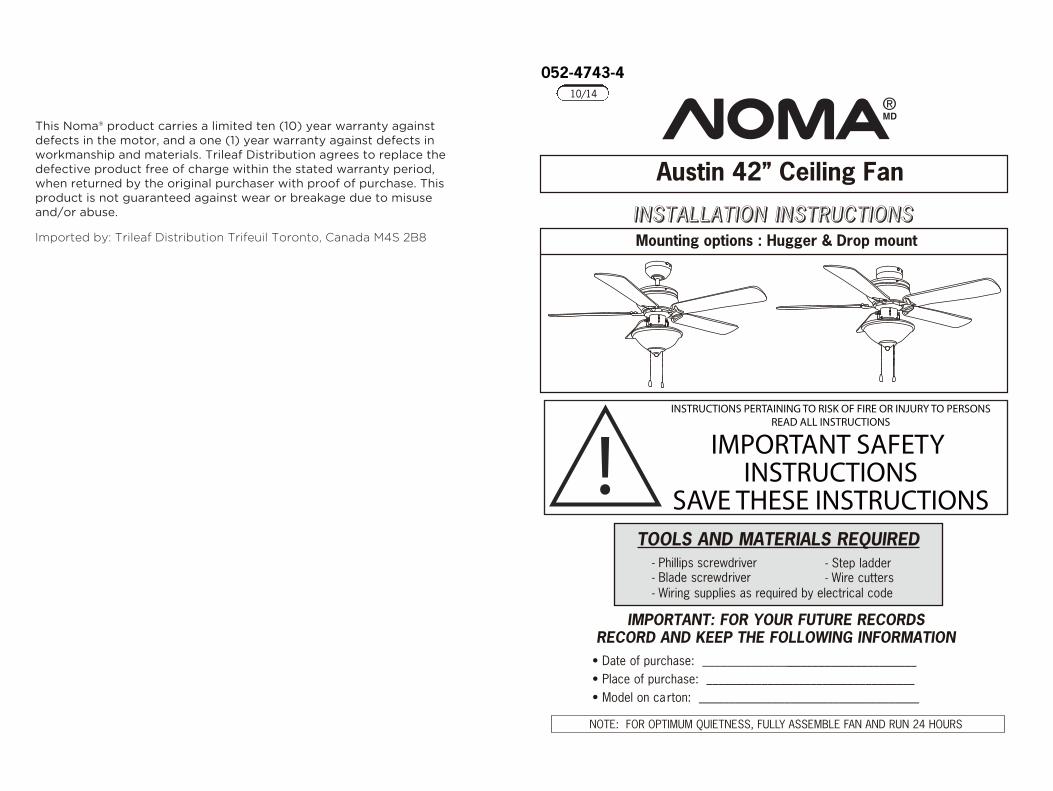
This Noma® product carries a limited ten (10) year warranty against defects in the motor, and a one (1) year warranty against defects in workmanship and materials. Trileaf Distribution agrees to replace the defective product free of charge within the stated warranty period, when returned by the original purchaser with proof of purchase. This product is not guaranteed against wear or breakage due to misuse and/or abuse. IINNSSTTAALLLLAATT IIOONN IINNSSTTRRUUCCTT IIOONNSS
Mounting options : Hugger & Drop mount
NOTE: FOR OPTIMUM QUIETNESS, FULLY ASSEMBLE FAN AND RUN 24 HOURS
IMPORTANT: FOR YOUR FUTURE RECORDSRECORD AND KEEP THE FOLLOWING INFORMATION
• Date of purchase: ___________________________________• Place of purchase: __________________________________• Model on carton: ____________________________________
!INSTRUCTIONS PERTAINING TO RISK OF FIRE OR INJURY TO PERSONS
READ ALL INSTRUCTIONS
IMPORTANT SAFETY INSTRUCTIONS
SAVE THESE INSTRUCTIONSTOOLS AND MATERIALS REQUIRED
- Phillips screwdriver- Blade screwdriver
- Step ladder- Wire cutters
- Wiring supplies as required by electrical code
Austin 42” Ceiling Fan

11
2
INSTRUCTIONSA ceiling fan has a completely internal switching system for total operation by
way of pull chains.On a fan/light combination, pull chains will exist: one for light,on and off. The second is for fan speeds. This will be marked ( ) on the fanswitch housing.
1st pull will give fan high speed2nd pull will give fan medium speed3rd pull will give fan low speed4th pull will shut fan o ff
The third pull chain is for forward/reverse. (Note: Some models come with a slideswitch instead of a pull chain). This setting would usually be changed twice peryear. Downdraft in summer to create a wind chill to give a cooling effect. Updraftin winter to circulate the hot stratified air off the ceiling and back down to the floorwithout creating a wind chill.
SAFETY PRECAUTIONS1. Turn off power at main electrical service box before starting installation.2. Electrical connections must comply with local code ordinances, national
electrical codes, CEC, NEC and ANSI/NFPA 70.3. Make sure the installation site you choose allows the fan blades to rotate
freely without any obstructions.4. When mounting the fan on a ceiling outlet box, use an approved (CSA for Canada and UL for U.S.) ceiling fan box marked "FOR FAN SUPPORT".
5. WARNING: To reduce the risk of fire, electric shock, or personal injury, mount fan only to an outlet box marked acceptable for fan support and use mounting screws provided with the outlet box. Most outlet boxes commonly used for the support of lighting fixtures are not acceptable for fan support and may need to be replaced. Consult a qualified electrician if in doubt.
Ensure the outlet box is securely installed in place such that it is able tosupport at least the fan weight.
three
WARNING- To reduce the risk of fire or electrical shock DO NOT use this fan with any solid state speed control device.
- To reduce the risk of personal injury DO NOT bend the blade brackets when installing the brackets, balancing the blades or cleaning the fan. Also, DO NOT insert foreign objects in between rotating fan blades.
- Mount with the lowest moving parts at least 7' (2.1 meters) above floor or grade level.
- DO NOT operate reversing switch while fan blades are in motion. Fan must be turned off and rotating blades stopped, reverse chain pulled, the speed chain pulled again to start in the opposite direction.
6. Total Fan Weight For Reference: 42"approximate 11 lb 4 oz (5.1 kg).
3
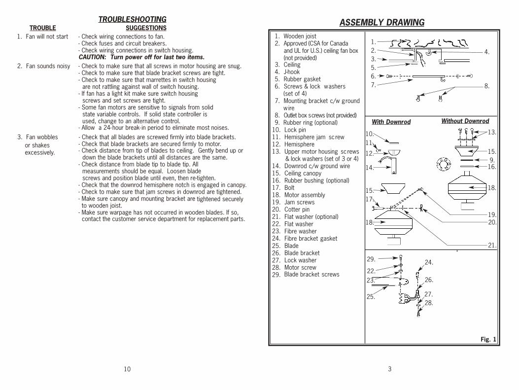
1. Wooden joist2. Approved (CSA for Canada
and UL for U.S.) ceiling fan box (not provided)
3. Ceiling4. J-hook5. Rubber gasket6. Screws & lock washers
(set of 4)7. Mounting bracket c/w ground
wire8. Outlet box screws (not provided)9. Rubber ring (optional)
10. Lock pin11. Hemisphere jam screw12. Hemisphere13. Upper motor housing screws
& lock washers (set of 3 or 4)14. Downrod c/w ground wire15. Ceiling canopy16. Rubber bushing (optional)17. Bolt18. Motor assembly19. Jam screws20. Cotter pin21. 22. 23.
Flat washer (optional)
24.
bracket screws
25.
Flat washer
26.
Fibre washer
27.
Fibre bracket gasket
28.
Blade
29.
Blade bracket Lock washer Motor screw
With Downrod Without Downrod
1.2.3.
4.
5.6.7. 8.
10.11.
12.
13.
14.
15.17.
18.
15.
16.
18.
19.20.
21.
22.
23.
25.
ASSEMBLY DRAWING
24.
26.
27.28.
29.
10
Fig. 1
9.
Blade
TROUBLESHOOTINGTROUBLE SUGGESTIONS
- Check fuses and circuit breakers.1. Fan will not start - Check wiring connections to fan.
- Check wiring connections in switch housing.CAUTION: Turn power off for last two items.
2. Fan sounds noisy - Check to make sure that all screws in motor housing are snug.- Check to make sure that blade bracket screws are tight.- Check to make sure that marrettes in switch housing
are not rattling against wall of switch housing.- If fan has a light kit make sure switch housing
screws and set screws are tight.- Some fan motors are sensitive to signals from solid
state variable controls. If solid state controller isused, change to an alternative control.
- Allow a 24- hour break- in period to eliminate most noises.
3. Fan wobbles - Check that all blades are screwed firmly into blade brackets.or shakes excessively.
- Check that blade brackets are secured firmly to motor.- Check distance from tip of blades to ceiling. Gently bend up or
down the blade brackets until all distances are the same.- Check distance from blade tip to blade tip. All
measurements should be equal. Loosen blade screws and position blade until even, then re-tighten.
- Check that the downrod hemisphere notch is engaged in canopy. - Check to make sure that jam screws in downrod are tightened.- Make sure canopy and mounting bracket are tightened
securely
to wooden joist.- Make sure warpage has not occurred in wooden blades. If so, contact the customer service department for replacement parts.

4
NOTE: All set screws must be checked and retightened where necessary, before and after installation.
MOUNTING OPTIONS
CAUTIONUpper jamscrew
Upper jamscrew
Do not loosen two lower jam screws
Bolt YokeYoke
Flat washer
Cotterpin
INSTINSTALLAALLATIONTION
DOWNROD MOUNT
- Position downrod inside canopy.- Route wires exiting yoke on motor through ceiling canopy and downrod.- Position downrod/canopy into yoke and align holes in yoke and downrod.- Insert bolt through hole in yoke and downrod. Be careful not to damage
or cut the fan wires.- Install the flat washer to the bolt. Secure with cotter pin through hole in the end of the bolt.
- Secure downrod in position by tightening upper jam screws.
1.
A
FLUSH MOUNT - Optional for some models.
- Remove rubber ring from canopy (see Fig. 2d).- Remove the upper motor housing screws. - Position canopy over corresponding holes on motor and secure with the upper motor housing screws, ensuring the rubber bushing is placed between the canopy and the motor.
B
Fig. 2a Fig. 2b
Fig. 2c
- Remove light kit screws and washers.- Connect polarized connectors of light kit to corresponding connectors
found in switch housing.
WARNING: BE SURE TO TURN OFF POWER BEFORE INSTALLING.- Carefully tuck electrical wires back into switch housing, align light kit with
switch housing and secure with three light kit screws and washers.-
Install
proper
wattage
and
type
of bulb
identified on light housing or shade.
- Place glass on light housing and secure (See Fig. 10a, Fig.10b).
9
White wire
White wire
Light kitscrews
Glass
DecorativecoverFinial
Fibre washerNut
Fig. 10b
Fig. 10a
Rubber washer
Steel washer
Red or BlueWires
Black or BlueWires
8. LIGHT KITS
NOTE:Electrical diagrams are for reference only. Light kits that are not packed with the fan must be CSA/UL listed and marked suitable for use with the model fan you are installing. Switches must be CSA/UL general use switches. Refer to the instructions packaged with the light kits and switches for proper assembly.
- Use a square-head screwdriver loosen the two upper jam screws on the yoke.
Motor
Canopy
Upper motor housing screws & lock washers
Rubber bushing
Canopy
Rubberring
Fig. 2d Fig. 2e WARNING: Ensure that all connections, set screws and screws are securely tightened before the next step.
8
5
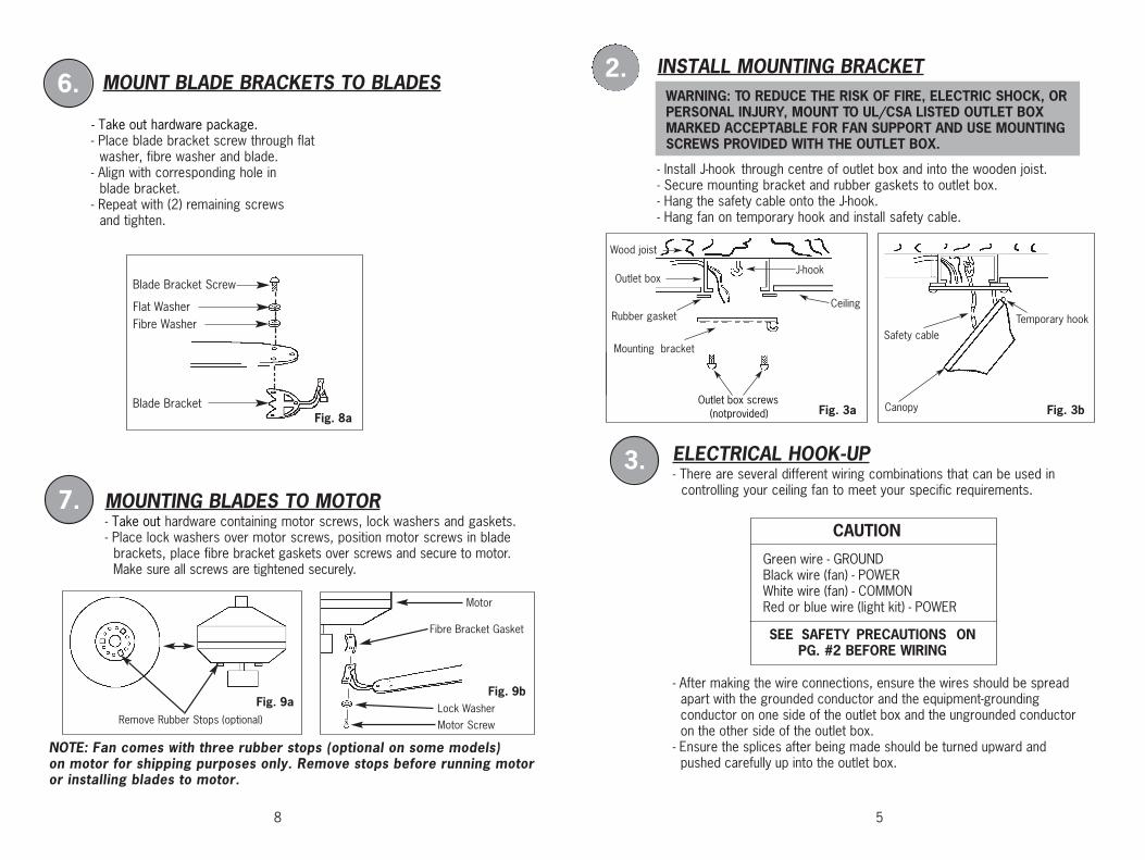
INSTALL MOUNTING BRACKET
- Install J-hook through centre of outlet box and into the wooden joist.- Secure mounting bracket and rubber gaskets to outlet box.- Hang the safety cable onto the J-hook.- Hang fan on temporary hook and install safety cable.
Canopy
Safety cableTemporary hook
J-hook
Ceiling
Wood joist
Outlet box
Rubber gasket
Mounting bracket
2.
Style#2
Fig. 3a Fig. 3b
WARNING: TO REDUCE THE RISK OF FIRE, ELECTRIC SHOCK, OR PERSONAL INJURY, MOUNT TO UL/CSA LISTED OUTLET BOX MARKED ACCEPTABLE FOR FAN SUPPORT AND USE MOUNTING SCREWS PROVIDED WITH THE OUTLET BOX.
MOUNT BLADE BRACKETS TO BLADES
Motor Screw
Motor
Lock Washer
Fibre Bracket Gasket
- Place blade bracket screw through flat
washer, fibre washer and blade.- Align with corresponding hole in
blade bracket.- Repeat with (2) remaining screws
and tighten.
MOUNTING BLADES TO MOTOR- Take out hardware containing motor screws, lock washers and gaskets.- Place lock washers over motor screws, position motor screws in blade
brackets, place fibre bracket gaskets over screws and secure to motor. Make sure all screws are tightened securely.
6.
7.
Remove Rubber Stops (optional)
NOTE: Fan comes with three rubber stops (optional on some models) on motor for shipping purposes only. Remove stops before running motor or installing blades to motor.
Fig. 9aFig. 9b
Blade Bracket Screw
Fibre WasherFlat Washer
Blade BracketFig. 8a
- Take out hardware package.
Outlet box screws(notprovided)
CAUTION
SEE SAFETY PRECAUTIONS ONPG. #2 BEFORE WIRING
ELECTRICAL HOOK-UP- There are several different wiring combinations that can be used in
controlling your ceiling fan to meet your specific requirements.
3.
- After making the wire connections, ensure the wires should be spread apart with the grounded conductor and the equipment-grounding conductor on one side of the outlet box and the ungrounded conductor on the other side of the outlet box.- Ensure the splices after being made should be turned upward and pushed carefully up into the outlet box.
Green wire - GROUNDBlack wire (fan) - POWERWhite wire (fan) - COMMONRed or blue wire (light kit) - POWER
6
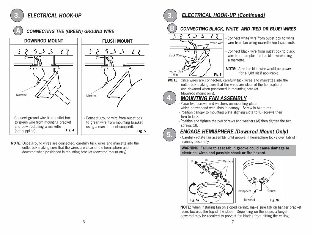
ELECTRICAL HOOK-UP
3.
7
MOUNTING FAN ASSEMBLY
ENGAGE HEMISPHERE (Downrod Mount Only)- Carefully rotate fan assembly until groove in hemisphere locks over tab of
canopy assembly.
4.
5.
WARNING: Failure to seat tab in groove could cause damage to electrical wires and possible shock or fire hazard.
ELECTRICAL HOOK-UP (Continued)
CONNECTING BLACK, WHITE, AND (RED OR BLUE) WIRES
NOTE: Once wires are connected, carefully tuck wires and marrettes into the outlet box making sure that the wires are clear of the hemisphere and downrod when positioned in mounting bracket (downrod mount only).
Red or BlueWire
Black Wire
White Wire
3.
B- Connect white wire from outlet box to white wire from fan using marrette (no t supplied).
- Connect black wire from outlet box to blackwire from fan plus (red or blue wire) using a marrette.
NOTE: A red or blue wire would be power for a light kit if applicable.
CONNECTING THE (GREEN) GROUND WIRE
- Connect ground wire from outlet box to green wire from mounting bracket and downrod using a marrette(not supplied).
NOTE: Once ground wires are connected, carefully tuck wires and marrette into the outlet box making sure that the wires are clear of the hemisphere and downrod when positioned in mounting bracket (downrod mount only).
- Connect ground wire from outlet box to green wire from mounting bracketusing a marrette (not supplied).
DOWNROD MOUNT FLUSH MOUNT
Marrette Marette
A
- Place two screws and washers on mounting plate which correspond with slots in canopy. Screw in two turns.
NOTE: When installing fan on sloped ceiling, make sure tab on hanger bracket faces towards the top of the slope. Depending on the slope, a longer downrod may be required to prevent fan blades from hitting the ceiling.
Downrod
Hemisphere Groove
(A)(B)
(B)
Washers
(A)
Fig.7bFig.7a
- Position canopy to mounting plate aligning slots to (B) screws then turn to lock.- Position and tighten the two screws and washers (A) then tighten the two screws (B).
Fig.6
Fig. 5Fig. 4