australian construction achievement award 2011 … · australian construction achievement award...
TRANSCRIPT

ACAA Technical Paper John Holland APCTX50_Rev A.docx Page 1
AUSTRALIAN CONSTRUCTION ACHIEVEMENT AWARD 2011
Finalist Submission
John Holland – Complexity, difficulty and optimisation associated with the construction of Abbot Point Coal Terminal Berth 2 and
second Shiploader
Technical Conference Paper
Andrew Mattiske1
1 ABSTRACT
John Holland Pty Ltd in association with their client the North Queensland Bulk Ports Corporation (NQBP) have delivered the vital second berth and coal outloading stream at Queensland’s Abbot Point Coal Terminal. This terminal expansion was an essential response to the current global demand for coal in a boom resource market where project program overruns are prevalent. The Abbot Point Coal Terminal (APCT) is located approximately 25 kilometres north of Bowen and is Australia’s most northerly coal port. North Queensland Bulk Ports Corporation is further expanding the capacity of the port to 50 million tonnes per annum. The terminal expansion comprised of the construction of Berth 2, a new 500-metre long berth east of the existing Berth 1, approximately 2.85 kilometres offshore. Construction of the berth involved driving 205 piles and the installation of approximately 9,500 tonnes of structural steel. Additionally, John Holland undertook the construction of: a shipping conveyor and associated drive tower; a second 2.9 kilometre jetty conveyor including all associated structural, mechanical and electrical works; and modifications at the head end of the jetty conveyor with the existing transfer tower. John Holland also undertook the construction of the APCT Shiploader SL2. This involved the structural, mechanical and electrical supply, fabrication, erection and commissioning of a 7,200 tonnes per hour coal Shiploader and tripper assembly weighing over 1,340 tonnes and standing at over 50 metres high.
2 KEYWORDS
ACAA, NQBP, PCQ. North Queensland Bulk Ports, Ports Corporation of Queensland, John Holland Pty Ltd, Abbot Point Coal Terminal, APCTX50, Abbot Point Coal Terminal X50 Expansion Project, Wharf, Berth, Shiploader, Australian Construction Achievement Award
1 John Holland Pty Ltd, 1000 Ann Street Fortitude Valley, 4006, Queensland. [email protected]
ACAA Technical Paper John Holland APCTX50_Rev A.docx Page 2
3 INTRODUCTION
The challenge for John Holland was to deliver this project in quick time with minimal disruption to the existing coal handling operations and shipping movements. The construction methodologies adopted by John Holland for the project met this challenge, delivering complex high risk works safely in a marine environment. John Holland undertook much of the work using direct labour and employed its marine experience to develop, amongst other things, “over the top” piling solutions to facilitate safe and speedy construction. John Holland successfully managed the complex interface between the manufacture and delivery of the massive 1,340 tonne Shiploader and the Berth construction works, ensuring delivery to the overall program. The Abbot Point Coal Terminal expansion will greatly enhance Queensland’s coal export capability and is a credit to the North Queensland Bulk Ports Corporation and John Holland.
4 SCOPE OF WORK
Traditional lump sum contracts were used to deliver this project. Irrespective of the type of contract, John Holland and the North Queensland Bulk Ports Corporation adopted a partnering approach to its delivery; both parties recognised the need to maintain strong business relationships whilst working in a complex, fast tracked construction environment. The overall scope of work for included the following major components;
4.1 Berth 2 (Marine Works) • Construction of a 280 metre long Berth 2 wharf with western strongpoint, longitudinal anchor
structure and eastern drive tower platform, including structural steel piling, headstocks, rail girders, rails, pre-stressed concrete deck units, conveyor support structures, associated steelwork and concrete;
• Construction of new mooring dolphins and new berthing dolphins, including structural steel piling, head-stocks, flooring, steelwork, fendering and mooring equipment and interconnecting trusses and walkways;
• Construction of a wharf bridge and transfer tower platform extension, providing roadway connection and wharf conveyor support between Berth 2 and the existing transfer tower platform.
4.2 Jetty Conveyor C334 (Marine Works) • Tail end conveyor and conveyor walkway support structure, built upon the Sample Plant 2 C334
Tail end floor structure (constructed by others); • Onshore trestles and conveyor galleries from the Sample Plant 2 tower to Jetty Bent 1, built upon
concrete foundations constructed by others; • Offshore conveyor galleries along the typical jetty, mounted upon new stainless steel plates
welded to the existing headstock shoes, including conveyor cross-over ladders and platforms; • Offshore trestles and conveyor galleries with fully sealed flooring at the offshore end of the
conveyor where it rises to the existing C324 / C334 drive tower (the offshore transfer tower), including brake platform, and gravity take-up unit with fall arrestor assembly;
• Modifications to the existing C324 / C334 drive tower to accept the new conveyor installation, and head end conveyor support, conveyor access, and chute-work support structure within the tower.
4.3 Wharf Conveyor C335 (Marine Works) • Tail end conveyor support and conveyor access structure; • Trestles and clad truss conveyor galleries with fully sealed flooring from the tail end structure to
the western-most tripper travel extent adjacent to the Berth 2 strongpoint; • Continuously welded beam-type open conveyor galleries for the length of Berth 2, which support
the conveyor and provide the running beams for the Shiploader SL2 tripper;

ACAA Technical Paper John Holland APCTX50_Rev A.docx Page 3
• Brake platform, and gravity take-up unit with fall arrestor assembly near the head end; • Elevated, clad drive tower at the eastern end of Berth 2.
Figure 1 - Marine Works General Arrangement
4.4 Shiploader • Development of a construction and preassembly strategy for components in Brisbane; • Assembly and testing of components to the greatest extent possible prior to relocation of the
Shiploader SL2 to Abbot Point Coal Terminal utilising a Heavy Lift Vessel (HLV); • Development and testing of the Boom Luffing System is required to enable adequate clearance
from the Gateway Bridge in Brisbane to be achieved; • Development and conduct of an installation methodology for locating the Shiploader onto the new
marine works.

ACAA Technical Paper John Holland APCTX50_Rev A.docx Page 4
Figure 2 - Shiploader General Arrangement
5 TEMPORARY WORKS DESIGN
The Permanent works design, with some exceptions, was undertaken by NQBP. John Holland was fully responsible for the design and implementation of all temporary works.
5.1 Scope X50 Marine Works As the preferred contractor, John Holland assisted the designer with adding constructability into the design. This included:
• Incorporating learnings in constructability of the recently completed Dalrymple Bay Coal Terminal 7X works in the design details of the new wharf and dolphin structures;
• Wharf Bridge span optimisation; • Dolphin design - revisions and preassemblies to raise all works above wave zone (this allowed a
work platform to be installed that was suitable for encapsulation to capture grit blasting - environmental best practice for this sort of work). This also minimised work offshore;
• Construction loads could potentially become the critical design case for the structurally skeletal framed new wharf. All construction loads affecting the permanent works were analysed and operations and work sequences implemented to ensure that the permanent structure was not overstressed at any stage. For example, the wharf structure was temporarily braced longitudinally until sufficient permanent structure was completed to provide the structural capacity necessary to support the three large construction rigs even in a one in 250 year cyclone event.

ACAA Technical Paper John Holland APCTX50_Rev A.docx Page 5
5.2 Scope X50 Shiploader The permanent works design was completed by the NQBP. Extensive temporary works design was completed by John Holland including:
• Assembly stability checks; • Review of construction loads on components during construction; • Design of the sea fasteners for the ocean transportation of the Shiploader; • Development of the methodology for unloading the Shiploader at Abbot Point using bumpers,
stabbing guides and tailing winches in conjunction with the cranes on the HLV.
5.3 Use of 3D Drawings and Animations During tender stage, John Holland produced an animation of the proposed construction methodology based on 3D CAD drawings in order to demonstrate to NQBP that the complexity of the project was understood. The animation at this early stage proved the viability of the proposed construction strategy and had the following additional benefits:
• Marketing of methodology and competency to NQBP; • Clarification of the methodology for all project participants; Highlighted (and solved) complex
interfaces in the works; • Provided basis for design development of both permanent and temporary works; • Identification of interfaces and clashes with permanent and temporary works; • Visualisation of construction plan (big picture) for workforce - used for site inductions.
This enabled the development of the integrated construction system required for a successful and safe over-the-top offshore construction method. The permanent works, temporary works, three crane rigs, a piling traveller, multiple work platforms and temporary bracing, all acted together in providing a safe and stable offshore work platform.
5.4 Development of Outriggers with Tension Capacity The installation of 3 kilometres of new galleries on the existing jetty was accomplished using a specially designed gallery transporter developed by John Holland. The transporter could quickly deliver and place in position a 24-metre conveyor gallery on the narrow jetty roadway in less than a hour. This minimised disruptions to the operations of the existing Berth 1 for coal exports. The narrowness of the roadway prevented outriggers of the required spread to be deployed, so the project developed a stabiliser that clamped to the jetty roadway deck and provided the required uplift capacity to allow the gallery to be lifted into place.
5.5 Rescue Boat As the port operator’s rescue boat and process was inadequate for project work, the project team designed a process that enable the rescue crew to safely enter the rescue craft while in its cradle on the berth, connect dual purpose fall protection/ floatation devices and be lowered in the boat over the side. This process was essential in eliminating the risk of injury by the crew attempting to enter the boat from a ladder while the boat was on the weather side of the berth. The installation of the boat, cradle and launch gantry crane was supplemented by training tailored specifically to the equipment and process and was provided by John Holland employees.
5.6 X50 Shiploader Assembly Sequence The assembly sequence was used previously. This was enhanced via maximising preassembly of components and utilisation of larger assembly cranes. At John Holland’s initiative, the electrical switchroom was redesigned to a modular structure allowing erection of steelwork for the switchroom, fixing of cladding and installation of VSD and MCC switchboards

ACAA Technical Paper John Holland APCTX50_Rev A.docx Page 6
to be completed at an adjacent assembly area and consequently, have no impact on the program for erection of the main structure for the Shiploader.
6 COMPLEXITY, DIFFICULTY AND OPIMISATION OF THE CONSTRUCTION TASK – MARINE WORKS
6.1 Logistics Outline The APCT X50 project construction works demanded minimal disruption to the terminal operations and shipping movements. It also required coordination between the related projects to happen concurrently at the terminal with other contractors. To achieve this, John Holland developed a specific and agreed Traffic Management Plan (TMP) and Communications Protocol for the project. In particular, the TMP provided clarity to all parties on where dedicated vehicle, crane and pedestrian zones where and when traffic control was required. In addition, site notices and notifications where issued to all parties for John Holland construction logistic movements that may have had an impact on others. Onshore preparation works were required prior to the installation of permanent works to reduce the amount of work over water, and the sheer size of the permanent works being delivered to site to accommodate road transport restrictions. This included splicing of piles and preassembly of major structures and an enclosed painting facility for repairs. Due to other projects being undertaken concurrently and the terminal being operational, onshore laydown areas and a Load Out Facility (LOF) for marine deliveries were setup. These were external and adjacent to the terminal with vehicle access through gate 14. This enabled John Holland to be in control and manage the logistics physically, separating the construction activities from other parties and operations. For example, the haul road adjoining the laydown and the LOF required continuous closures for transporting large preassembles such as: 40 metre long dolphin trusses and the 14 metre x 14 metre x 10 metre drive tower structure. The limited space of the laydown and LOF areas could not accommodate all construction and permanent materials, resulting in a “Just in Time” delivery process to be adopted. This was achieved through strong internal and external relationships, and coordination between the project and the John Holland’s Richlands and Rockhampton workshop teams. The constructed LOF was the hub to the project construction, as the only access to the berth construction was along a single lane 3 kilometre jetty, making the LOF essential for the project logistical activities. To reduce construction traffic and clear access for operations, restrictions to the amount of vehicles to and from the berth work front (via the jetty) were enforced. Buses where provided at shift changes for personnel and any closures of the jetty for large items was coordinated with all parties and site notices were issued. The berth construction materials were transported from the onshore laydown to the LOF and delivered to the work front via marine vessels. This created different obstacles to contend with such as tides, wind, waves, etc, which were managed by the project team, utilising John Holland’s unique marine construction techniques and the team’s previous marine construction experience. Early communication and consultation with the Regional Harbour Master (Bowen) was critical for the marine logistics. This relationship allowed safe anchorage for all marine vessels on the project for adverse weather conditions and included the cyclone moorings, any notices to mariners and shipping/tug movements. Preassembled conveyor galleries for the jetty were delivered to site and set out in the laydown yard in the construction installation sequence. John Holland’s unique design and custom built trailer with twin large HiAb’s (the gallery transporter, as discussed in section 3, Innovations), a presentation of the transporter operating to the terminal operations, coordination with shipping scheduler, and constant communication with the shift and maintenance supervisors were essential to the smooth uninterrupted installation of the jetty conveyor. Flooding (affecting transport) and weather (affecting painting) delayed the delivery of these conveyor galleries to site. However, through utilising an experienced team on night shift, a new and

ACAA Technical Paper John Holland APCTX50_Rev A.docx Page 7
improved design to the transporter, and communication with operations, the installation of the jetty conveyor was able to meet the construction program.
6.2 Interaction with Port Operations Construction works were not to disrupt existing coal handling operations and shipping movements. The Port operated, prior to the upgrade, with one berth and one Shiploader continually around the clock, with shipping movements governed by both the coal loading activities and the tides. Fully laden ships require a high tide to allow movement from the berth. To ensure minimal disruption, the Port operations were physically separated from construction activities. This restricted available construction lay down area and resulted in interface activities being undertaken during maintenance shutdowns. The areas within John Holland’s construction activities where interaction with port operations had a potential to occur were:
• Supply of materials to work fronts on water by barge; • Shared use of the 3 kilometre long single-lane access jetty to the new wharf; • Works performed on upgrading the existing outloading facilities.
The contract requirements provided for uninterrupted use of the existing outloading facilities by port operations, and for the contractor to coordinate its operations to achieve this. John Holland achieved these goals by maintaining regular coordination with port operations and planning its operations to avoid any interference with them. Major success was achieved in:
• Maximising the use of barge supply to minimise use of the jetty access for transporting materials to offshore work fronts;
• Daily checking of planned shipping movements advised by port operations, coordination and consultation through the Ports shift supervisor;
• Weekly coordination meetings with the port operations and other contractors to manage and advise of construction activities and interfaces potentially affecting the facility and other projects being conducted concurrently. In addition to the meetings, site notices were issued to all parties in accordance with the projects Traffic Management Plan;
• Use and implementation of the John Holland site specific communications protocol. In particular, the use of marine radio channels by tug operators to keep in touch with any changes to Port Operations shipping movements;
• Nightshift working on installation of the new outloading conveyor system along the 3 kilometre long single-lane jetty to minimise interface with Port and government services that need access to existing wharf and berthing vessels;
• Planning works on existing outloading systems to be performed during maintenance shut downs on these facilities. In particular, an extension to the existing wharf conveyor tail end, installation of additional chutes to the existing jetty conveyor and tie-in to the new outloading conveyor system was performed during a maintenance shut down concurrent with installation of the new wharf, thereby avoiding the need for a special shut down to perform these works after commissioning the new works as anticipated in the Contract.
6.3 Onshore Assembly 6.3.1 Drive Tower Roof Structure The C335 Conveyor Drive Tower at Abbot Point X50 was a 14 metre (wide) x 9 metre (wide) x 23 metre (high) steel framed structure, with a central level formed by concrete panels on a steel framed floor. To minimise the offshore works, the Drive Tower was pre-assembled onshore, and installed offshore in pieces;
ACAA Technical Paper John Holland APCTX50_Rev A.docx Page 8
• 14 metre x 14 metre steel side frames; • 14 metre x 9 metre steel floor structure; • Humeslab precast panels (installed on top of steel floor structure, designed to act as formwork for
topping slab); • 14 metre x 9 metre x 9 metre (high) roof structure.
The critical onshore preassembly works was associated with the roof structure (14 metre x 9 metre, by 9 metre high) which was fully assembled onshore including gantry crane beams and access walkways. The connections were painted and the structure clad with metal sheeting (except for cut-outs at the four corners required to gain access to lifting lugs). Lift lugs were designed to not interfere with the sheeting so the cut-outs could be easily clad offshore (minimising rework associated with cutting off the lugs and painting).
6.3.2 Dolphin Access Bracing The access platforms for the berthing dolphins (suspended off the adjacent berth structure) were designed to support the bottom gate for pile driving, as well as acting as the temporary bracing for the piles and provide full access around the piles for pile cut-off and welding. After installation of the headstock assembly and completion of painting works, the access bracing was removed in pieces, and reassembled onshore to be installed as one piece for the next dolphin construction.
6.3.3 Longitudinal Wharf Bracing The wharf construction required temporary longitudinal bracing, to resist construction loads, prior to construction of the permanent longitudinal anchor. The temporary longitudinal bracing need to be installed at a level on the piles that was not readily accessible for welding and painting works, therefore the bracing was designed with clamp connections to the piles to minimise rework.
6.3.4 Gallery Transporter The gallery transporter comprised of a purpose built trailer with two hydraulic HIAB knuckle booms, one at each end, for handling 24-metre long conveyor galleries weighing 16 tonne at 5 metre radius. The galleries were loaded onto the transporter at the onshore storage area using either the knuckle booms or a pair of Franna cranes. A prime mover towed the transporter into position on the jetty adjacent to the position into which the gallery was to be installed. In order to stabilise the transporter during the unloading activity, two purpose-designed tension ties were attached between the headstocks and the transporter on one side while two outriggers were extended and jacked down on the loaded side. The hydraulic knuckle booms were then used to lift the gallery from the transporter onto the installed position on the supporting headstocks. The transporter was capable of installing up to five galleries during a shift.
6.4 Interface between the Marine Works and Shiploader Construction Programs
The program for the manufacture and delivery of the Shiploader needed to be integrated with that of Marine Works construction. It was John Holland’s responsibility to manage this complex interface even though the work was awarded as two separate contracts. The Marine Works technical specification and contract milestones defined the interface points and the project team indentified a number of critical issues that needed to be addressed. These included the amount of the berth structure which was required to be completed to receive the HLV, and coordination of electrical infrastructure to provide power to the new Shiploader. The location of the Shiploader also complicated access in a very busy area of the wharf. Significant coordination was required to ensure the Shiploader and Berth construction did not obstruct each other. The compressed time frame required the establishment of amenities for both the

ACAA Technical Paper John Holland APCTX50_Rev A.docx Page 9
Shiploader construction and commissioning crew, which had the potential to block access to other marine works. Construction progress with the Berth at Abbot Point had to have sufficient berthing dolphins, fenders and mooring hooks completed to allow the HLV to dock at Abbot Point. Offloading Sea and Weather Conditions Design criteria for sea state during ocean transportation was 2.5 metres significant wave height. Additionally, the potential sea state during the unloading at Abbot Point had to be addressed in the methodology for unloading the Shiploader.
6.5 Marine Environment Importance (and Sensitivity) The project Environmental Impact Statement identified that conservation and protection of marine flora and fauna was a critical priority, as a result the regulatory approvals for the project identified specific mitigation measures to achieve these requirements. In order to achieve compliance with these mitigation requirements, they were integrated into the CEMP through the establishment of clearly defined roles and responsibilities, the identification and management of risk and the establishment of key project control and hold points for critical activities. John Holland worked collaboratively with NQBP towards minimising environmental harm to the port and to the receiving areas. Of particular relevance were two specific construction activities of dredging and pile driving. Marine fauna monitoring was conducted in accordance with the dredging conditional requirements throughout the dredging operations to ensure no turtles, whales, or stingrays were harmed. Using pile driving techniques adapted for the project, daily monitoring of marine fauna was conducted to ensure no potential impact could occur. In addition, piles were prepared and painted onshore, thus reducing the environmental risk of activities over the marine environment. The Shiploader site was adjacent to Brisbane River so it was important to prevent any impacts to the river in terms of loss of material or water from site. This was achieved through the implementation of site controls to capture and prevent the loss of materials and substance such as abrasive blasting media and heavy machinery fuels/oils from the site. Erosion and sedimentation controls were also established to prevent stormwater runoff impacts to water quality in the river.
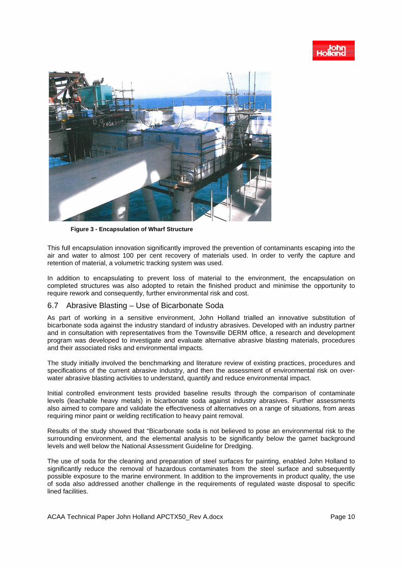
6.6 Abrasive Blasting and Painting Encapsulation With a commitment to continual improvement, the project strived to identify opportunities to go beyond current industry best practice. An example of continual improvement and innovation on the project was the methodology used for the encapsulation of abrasive blasting and painting works. This activity becomes quite complex and difficult in the establishment and maintenance of encapsulation around a structure in order to prepare and applying surface coatings. John Holland designed a method of full encapsulation for these works which included the development of zippered entrances, pile collars and fitted floor mats. This application was developed and implemented in a collaborative partnership with NQBP and other relevant stakeholders to exceed current industry practice. The objective of the full encapsulation was to contain the propelled stream of high pressured abrasive material and metal contaminates from entering the marine environment, particularly in an area with high winds and strong seas.
ACAA Technical Paper John Holland APCTX50_Rev A.docx Page 10
Figure 3 - Encapsulation of Wharf Structure
This full encapsulation innovation significantly improved the prevention of contaminants escaping into the air and water to almost 100 per cent recovery of materials used. In order to verify the capture and retention of material, a volumetric tracking system was used. In addition to encapsulating to prevent loss of material to the environment, the encapsulation on completed structures was also adopted to retain the finished product and minimise the opportunity to require rework and consequently, further environmental risk and cost.
6.7 Abrasive Blasting – Use of Bicarbonate Soda As part of working in a sensitive environment, John Holland trialled an innovative substitution of bicarbonate soda against the industry standard of industry abrasives. Developed with an industry partner and in consultation with representatives from the Townsville DERM office, a research and development program was developed to investigate and evaluate alternative abrasive blasting materials, procedures and their associated risks and environmental impacts. The study initially involved the benchmarking and literature review of existing practices, procedures and specifications of the current abrasive industry, and then the assessment of environmental risk on over-water abrasive blasting activities to understand, quantify and reduce environmental impact. Initial controlled environment tests provided baseline results through the comparison of contaminate levels (leachable heavy metals) in bicarbonate soda against industry abrasives. Further assessments also aimed to compare and validate the effectiveness of alternatives on a range of situations, from areas requiring minor paint or welding rectification to heavy paint removal. Results of the study showed that “Bicarbonate soda is not believed to pose an environmental risk to the surrounding environment, and the elemental analysis to be significantly below the garnet background levels and well below the National Assessment Guideline for Dredging. The use of soda for the cleaning and preparation of steel surfaces for painting, enabled John Holland to significantly reduce the removal of hazardous contaminates from the steel surface and subsequently possible exposure to the marine environment. In addition to the improvements in product quality, the use of soda also addressed another challenge in the requirements of regulated waste disposal to specific lined facilities.

ACAA Technical Paper John Holland APCTX50_Rev A.docx Page 11
With such a significant reduction of leachable contaminates, the successful case study has been recognised as an innovative development by the regulatory agency.
6.8 Work at Height One of the key risk activities was working at height, a detailed working at height strategy was developed to minimize risks associated with this activity;
• Eliminate if possible otherwise 100 per cent connection (zero tolerance). Project Management
realised from previous project experience that significant effort had to be expended on eliminating work at heights. To achieve this, all work at heights risks were identified in the early planning stages of the work to maximise the opportunity to design out OHS the risk. In some cases, methodologies were changed and scaffolding was used extensively to provide safe access to work areas. Where elimination was not possible a 100 per cent connection philosophy was adopted and implemented during the induction process. Reviews were carried out regularly on structures to identify suitable locations to install engineer designed anchorages for lanyards and static lines;
• Management of risks associated with workover- other-work areas was eliminated where possible by separation during planning or installation of solid guarding or barricading where the risk assessed was low;
• Planning for ‘Just-in-Time’ supply of construction products to the congested workfronts minimised risks associated with plant and personnel resulting in no injuries relating to plant/ personnel interface.
6.9 Extreme Weather Events The APCT X50 Marine Works project was exposed to some extreme weather events throughout its duration. To mitigate the risk to personnel and the project, John Holland developed project specific Emergency Response Plans (Day and Night Shifts), Cyclone Procedure, Emergency Procedures and Rescue Retrieval Procedures The Bowen region has a very distinct wet season, receiving 6 per cent of its average annual rainfall during the months of December, January and February. During the 2008/2009 wet season, Bowen received 1180mm of rain fall in January and February alone. This resulted in the 2008/2009 wet season having more than double (218%) its average rain fall. Refer Figure 4 - 2009 Bowen Rainfall Data. This resulted in erosion and flooding on the site, and the Bruce Highway on either side of the project site was cut-off with the substantial rainfall. This had to be monitored and controlled by the project team through erosion control (part of the Environmental Plan) and site evacuation for personnel.

ACAA Technical Paper John Holland APCTX50_Rev A.docx Page 12
Figure 4 - 2009 Bowen Rainfall Data
Similarly, the following wet season, 2009/2010 had one and a half times (149%) its average rainfall. Refer Figure 5 - 2010 Bowen Rainfall Data.
Figure 5 - 2010 Bowen Rainfall Data
A lot of this rainfall was generated by cyclone activity on, and around, the coast of Queensland. Several cyclones influenced the project, as listed below.
• Cyclone Charlotte – January 2009 • Cyclone Ellie – February 2009 • Cyclone Hamish – March 2009 • Cyclone Olga – January 2010 • Cyclone Ului – March 2010
The most significant of these cyclones was Cyclone Hamish and Cyclone Ului. Cyclone Hamish skirted down the coast of Queensland, passing offshore from Bowen as a category 5 cyclone. Please refer to Figure 6 - Tropical Cyclone Hamish, March 2009.

ACAA Technical Paper John Holland APCTX50_Rev A.docx Page 13
Figure 6 - Tropical Cyclone Hamish
Being a marine-based project, there was an array of floating plant supporting construction activities. As with the majority of the cyclones, it was necessary to demobilise all floating plant from the project site and secure it on protected cyclone moorings. Other site equipment and falsework was secured as the site was placed into cyclone lock-down. To carry out these activities in a safe and timely manner, the process and protocol was outlined in the Cyclone Procedure making this a valuable document. The procedure enabled the project to be secured and allowed employees to travel to and from home in a structured and safe manner. The most significant cyclone to affect the project - Cyclone Ului - headed on a direct course with Bowen as a category 3 cyclone before finally crossing the coast line just to the south. With its direct costal approach towards Bowen, the site was placed into cyclone lock-down and the construction camp was evacuated, in line with the Cyclone Procedure. Please refer to Figure 7 - Tropical Cyclone Ului.
Figure 7 - Tropical Cyclone Ului
In summary, the APCT X50 Marine Works project was exposed to some extreme weather events throughout its duration. These events created significant disruption to the work flow and to the safety of the employees, which was controlled by the project team through the Emergency Plans and Procedures.
ACAA Technical Paper John Holland APCTX50_Rev A.docx Page 14
7 COMPLEXITY, DIFFICULTY AND OPIMISATION OF THE CONSTRUCTION TASK – SHIPLOADER
7.1 Logistics Outline - X50 Shiploader The steelwork for the structure was fabricated at John Holland’s Richlands facility in the largest components that could be road transported across Brisbane to the assembly site at Morningside. Fabricated mechanical components such as bogies, winches and the vessel access ladder were subcontracted to specialist companies up and down the east coast of Australia. These items were preassembled to the fullest extent possible prior to delivery to the Morningside assembly site. After further work on the ground at Morningside, the steelwork was erected in large assemblies quite often using two John Holland Liebherr LR1280 cranes, one fitted with a superlift. Some of the signification lifts were as follows:
• Boom structure 60 metres long weighing 181 tonne (Heaviest Module); • Mast structure including platforms and masthead sheaves weighing 100 tonne.
The overall footprint of the Shiploader is approximately 16 metres x 16 metres. Combined with the multi-level nature of the machine, the requirement to minimise work crews working above or below each other was paramount. Piled foundations were utilised at the final assembly location to support the machine on its permanent wheel sets during construction. A review of the machine stability during construction was completed, imposing significant restraints on the erection sequence. It was imperative that components were received on site as required by the construction sequence or significant overall delays would have occurred. The technical specification for cast material provided to be the greatest challenge for suppliers. The fabrication permanent bogie (or wheelsets) was delayed. However, a complex series of struts and supports were required to be developed and installed to mitigate these delays. The main luffing winches required the manufacture of two ring gears. At the completion of a 22-week casting program, one of these was provided by the foundry in a suitable condition however the second gear was unusable. An additional 22-week period was unimaginable. The design was changed to a forged and welded assembly, procured from South Africa and delivered to the machine shop within a two month period, being available for machining shortly after completion of the first gear.
7.2 Availability and Capacity of Heavy Lift Vessel Arrangements were finalised with Big Lift Shipping for use of their HLV, “Happy Buccaneer” 18 months prior to the planned ocean transportation to Abbot Point. The lifting capacity of the two 700 tonne cranes on the HLV at the required working radius was limited to 1,250 tonne. This imposed further restrictions to the extent of work that could be completed at the assembly yard in Brisbane.
7.3 Availability of Dry Dock The Cairncross Dockyard at Morningside in Brisbane operated by Forgacs Engineering was the only facility in Queensland that allowed for an assembled Shiploader to be moved alongside a berth/dock that could be accessed by a HLV.

ACAA Technical Paper John Holland APCTX50_Rev A.docx Page 15
7.4 Completion of Second Bridge The clearance envelope for vessels passing below the Gateway Bridge in Brisbane (Sir Leo Hielscher Bridges) during the construction of the second bridge restricted the height of the Shiploader during ocean transportation to Abbot Point. The shipping channel below the two bridges was skewed to the centreline of the bridges adding further height restrictions. As a result of the height restrictions, significant work was required to complete the Shiploader at Abbot Point. The long travel bogies and equaliser beams were removed, and erection of all steelwork above the masthead sheaves and telescopic chute were deferred until after arrival at Abbot Point. The erection ships’ access ladder and installation of the boom conveyor belt were also completed after arrival at Abbot Point due to the weight restriction with the cranes on the HLV.
Figure 8 - HLV at Gateway Bridge in Brisbane
ACAA Technical Paper John Holland APCTX50_Rev A.docx Page 16
7.5 Shiploader Relocation - Ground, Sea and Weather Installation of Shiploader Boom:
• Existing ground conditions as the site had various zones of bearing capacities requiring careful
planning to match the allowable ground bearing capacities; • Wind speeds and inclement weather also had to be carefully monitored.
Delivery to Abbot Point Coal Terminal:
• Due to the close proximity of the Shiploader to the Gateway Bridge in consultation with the Port of
Brisbane, the maximum wind speed for travel along the Brisbane river was restricted. This resulted in a delay of one day waiting for favourable weather conditions;
• Similarly, at Abbot Point specific swell and wind conditions had to be met to allow unloading of the Shiploader. This also caused a delay of one day waiting for favourable weather conditions. Even with these delays the program was still met;
• The swell at Abbot Point meant that the load could not be controlled to a high degree of accuracy. To combat this, John Holland designed a series of bumper frames, landing guides and tugger winches to control the load. In addition to this, John Holland designed the bracing method of the bogies the Shiploader was to be landed on to be flexible, which allowed the bogies to move to the load and achieve a bolted connection with less than 10mm tolerance.
7.6 Asbestos Identification In relation to the impact of the identification of asbestos on site in Brisbane, a management plan implemented minimised delay to the works but had a substantial cost impact. Asbestos material was identified on site approximately sixteen weeks prior to the arrival of the HLV. In conjunction with the rectification work being undertaken on the luffing winches assemblies, this discovery had the potential to delay the vessel loading. An Asbestos Management Plan was developed and implemented to allow site works to recommence in a matter of days and be undertaken in conjunction with the required monitoring and clean up.
7.7 Shiploader Heavy Lifting With the Shiploader needing to be in several locations during the project lifetime there was some particularly challenging logistics required to ensure the heavy lifts occurred in a safe and timely manner.
7.7.1 Installation of Shiploader Boom: • The dry dock at the northern end of the site was very close but was operational for maintenance
of other ships during the construction period. This resulted in the need to calculate the ability to swing the load between the two cranes at the northern end of the site. At multiple stages there was only approximately 1 metre clearance to each crane’s boom;
• Due to program reasons, many other Shiploader components and construction activities needed to occur concurrently within the same site area. This further restricted the space available on site and limited the time available to conduct the lift.
• The constricted site made checking of the tail swing radius and clearance of the boom to the load critical;
• The boom pivot pins (required to pin the boom in position) were in a difficult position to place. A separate support to lay the pin and then insert overcame this problem;
7.7.2 Delivery to Abbot Point Coal Terminal: • Tidal conditions created programing constraints with a series of tides and lifting windows to be
met to stay on program. Detailed planning was undertaken to ensure all available windows of opportunity were utilised to ensure tidal windows could be used, for example identifying sufficient crews to undertake welding of the seafasteners whilst the HLV was in the dry dock;

ACAA Technical Paper John Holland APCTX50_Rev A.docx Page 17
• The hatch covers of the HLV could only be moved in a certain sequence, also restricted by the location of the ship, for example at the fit out berth or dry dock. Extensive consultation was undertaken to optimise the hatch covers and location of stowed items on the ship. This was a key factor in achieving the program;
• The wharf at Abbot Point was partially completed requiring access for construction crews. This had the effect of minimising the time available to prepare items such as tugger winches and props prior to arrival of the HLV and liaising with the construction crew of the wharf.
• The position of the lift points required working at heights which was overcome by the use of elevated work platforms. Delivery to Abbot Point Coal Terminal;
• The weight of the rigging required ancillary cranes to assist. The severity of this problem was minimised by rigging the Shiploader in Brisbane and allowing area on deck to store the rigging for sea voyage whilst the rigging remained attached to the Shiploader. This eliminated the need to re-rig the Shiploader in the more constricting marine environment at Abbot Point;
• The height of the Gateway Bridge prevented the Shiploader being transported with the boom in the sea fastened position. This problem was minimised by luffing the boom after the bridge and designing a simple boom locking mechanism that could be installed whilst the vessel was moving in calm waters downstream of the Gateway Bridge;
• The HLV was much lower than the wharf at Abbot Point requiring a specially designed gangway to be installed to allow access to the ship;
• This height difference also made the design of the tugger winch system more complicated.
7.8 Shiploader Commissioning Constraints It was imperative that the Shiploader boom luffing be operational prior to the loading of the Shiploader onto the HLV to allow for:
• Trimming/levelling of the complete Shiploader prior to lifting onto the HLV; • Lowering of the boom to allow transit under the Gateway Bridge in Brisbane.
ACAA Technical Paper John Holland APCTX50_Rev A.docx Page 18
8 CONCLUSION
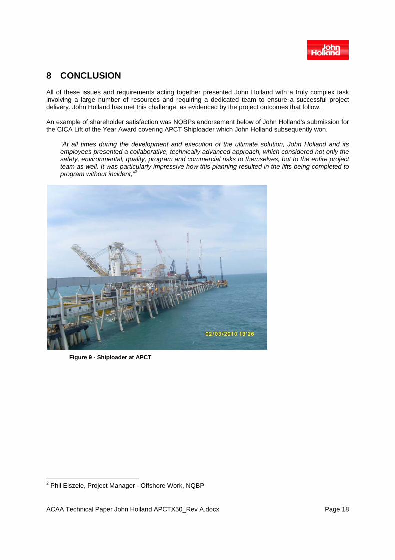
All of these issues and requirements acting together presented John Holland with a truly complex task involving a large number of resources and requiring a dedicated team to ensure a successful project delivery. John Holland has met this challenge, as evidenced by the project outcomes that follow. An example of shareholder satisfaction was NQBPs endorsement below of John Holland’s submission for the CICA Lift of the Year Award covering APCT Shiploader which John Holland subsequently won.
“At all times during the development and execution of the ultimate solution, John Holland and its employees presented a collaborative, technically advanced approach, which considered not only the safety, environmental, quality, program and commercial risks to themselves, but to the entire project team as well. It was particularly impressive how this planning resulted in the lifts being completed to program without incident,”2
Figure 9 - Shiploader at APCT
2 Phil Eiszele, Project Manager - Offshore Work, NQBP
ACAA Technical Paper John Holland APCTX50_Rev A.docx Page 19
9 REFERENCES
Award Submission - CICA Lift of the Year Awards. John Holland Lift of the Year Nomination Category A – for Cranes Over 130 tonne Lifting Capacity. Award Submission – ACAA Construction Achievement Award 2011 – Abbot Point Coal Terminal X50 Marine Works & Shiploader – John Holland. Abbot Point Coal Terminal X50 Upgrade – Marine Works – Contract Scope of Work; Aurecon Hatch and PCQ Abbot Point Coal Terminal X50 Upgrade – Shiploader – Contract Scope of Work; Aurecon Hatch and PCQ
10 ACKNOWLEDGMENTS
Whilst a single author is nominated for this paper the contribution of all John Holland Team in preparing documentation that provided details for this document is acknowledged. John Holland also thanks our client and all other individuals and parties involved for their contribution to the success of the project.