author: fardin barekat, electrical / mechanical engineer ... · 2. 1x load cell connector (ccs7-l)...
TRANSCRIPT
Document: WL100-V5 Author: Fardin Barekat, Electrical / Mechanical Engineer
1
WL100 – Wireless Load Cell Manual
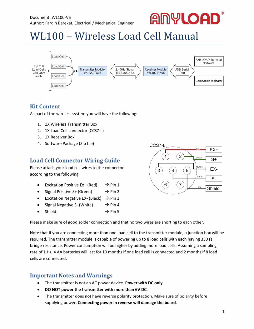
Kit Content As part of the wireless system you will have the following:
1. 1X Wireless Transmitter Box
2. 1X Load Cell connector (CCS7-L)
3. 1X Receiver Box
4. Software Package (Zip file)
Load Cell Connector Wiring Guide Please attach your load cell wires to the connector
according to the following:
Excitation Positive Ex+ (Red) Pin 1
Signal Positive S+ (Green) Pin 2
Excitation Negative EX- (Black) Pin 3
Signal Negative S- (White) Pin 4
Shield Pin 5
Please make sure of good solder connection and that no two wires are shorting to each other.
Note that if you are connecting more than one load cell to the transmitter module, a junction box will be
required. The transmitter module is capable of powering up to 8 load cells with each having 350 Ω
bridge resistance. Power consumption will be higher by adding more load cells. Assuming a sampling
rate of 1 Hz, 4 AA batteries will last for 10 months if one load cell is connected and 2 months if 8 load
cells are connected.
Important Notes and Warnings The transmitter is not an AC power device. Power with DC only.
DO NOT power the transmitter with more than 6V DC.
The transmitter does not have reverse polarity protection. Make sure of polarity before
supplying power. Connecting power in reverse will damage the board.

Document: WL100-V5 Author: Fardin Barekat, Electrical / Mechanical Engineer
2
DO NOT connect load cell combinations with less than 40Ω bridge resistance.
DO NOT position the transmitter or the receiver close to metal objects and make sure there are
no metal barriers between the transmitter and receiver.
Hardware Setup Instructions Open the transmitter box and install 4 standard AA batteries (not included) in the battery pack.
Connect the load cell wires to the provided connector according to the diagram above.
Plug in the load cell connector to the transmitter box. Make sure to do this before turning on the
transmitter. (Note that turning on the transmitter without connecting a load cell will not damage the
board, however the transmitter will be sending meaningless data to receiver).
To turn the transmitter on, press the switch on the transmitter box. The Transmitter is turned on when
the switch is in a low profile position.
When the transmitter is transmitting at 1 sample per second (1 Hz), the power consumption is very low
that 4 AA batteries can last 10 months. However, to conserve battery for even longer battery life,
remember to turn off the transmitter when not in use for long periods of time.
Software Setup Instructions The ANYLOAD Terminal Software is Windows based software running on 64bit architecture. The
software comes as a compressed zip file containing the main executable and other supplementary files
associated with the program. Please refrain from changing the directory structure, renaming or moving
of files outside the main directory.
Requirements: Please install Java8 on your computer before running the executable provided. Link:
https://www.java.com/en/download/
Once Java8 is installed, make sure the receiver is plugged in to your computer. Please disconnect all
other serial communication and USB ports from your computer except for mouse and keyboard.
When the receiver is plugged in, launch the “ANYLOAD_Terminal_V5_1” software.

Document: WL100-V5 Author: Fardin Barekat, Electrical / Mechanical Engineer
3
Software Usage Instructions The software has three different view modes based on access rights: User, Settings, and Calibration.
Each of these modes is presented below.
In the user mode, the operator can only interact with the software using the commands below:
Command Description
PEAL MODE Toggle the peak mode box
DATA LOG Toggles logging of generated data
Z1 Zero the display
T1 Set/Remove Tare
GR/NET Toggle between Gross and Net weight

Document: WL100-V5 Author: Fardin Barekat, Electrical / Mechanical Engineer
4
To activate the Settings Mode, the operator needs to enter the Global Setting Password. In Settings
Mode, the operator can use the following commands in addition to the commands in User Mode:
Command Description
RATE Change the sampling rate of the Transmitter Module
UNITS Change the display unit
DECIMAL Change the number of decimal points being displayed
LOCK Lock the Global Settings
Document: WL100-V5 Author: Fardin Barekat, Electrical / Mechanical Engineer
5
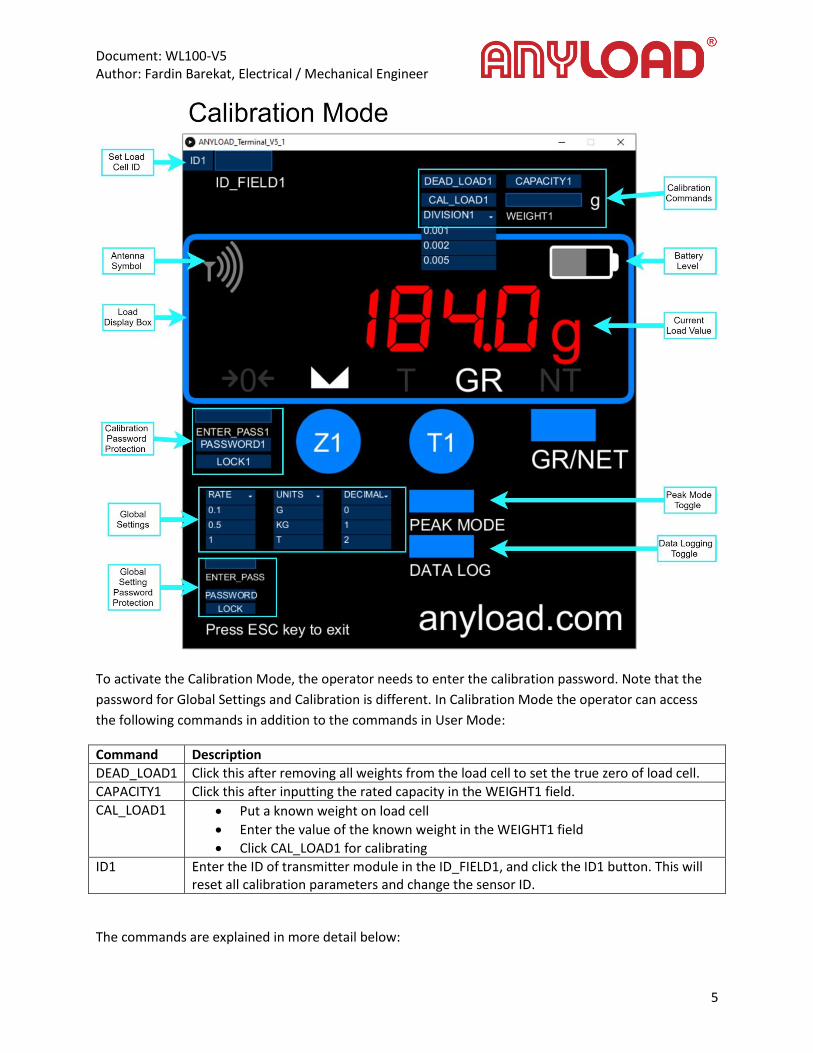
To activate the Calibration Mode, the operator needs to enter the calibration password. Note that the
password for Global Settings and Calibration is different. In Calibration Mode the operator can access
the following commands in addition to the commands in User Mode:
Command Description
DEAD_LOAD1 Click this after removing all weights from the load cell to set the true zero of load cell.
CAPACITY1 Click this after inputting the rated capacity in the WEIGHT1 field.
CAL_LOAD1 Put a known weight on load cell
Enter the value of the known weight in the WEIGHT1 field
Click CAL_LOAD1 for calibrating
ID1 Enter the ID of transmitter module in the ID_FIELD1, and click the ID1 button. This will reset all calibration parameters and change the sensor ID.
The commands are explained in more detail below:
Document: WL100-V5 Author: Fardin Barekat, Electrical / Mechanical Engineer
6
Linking Software with Load Cell Transmitter/Receiver Pair To link the software with the transmitter/receiver pair, first make sure:
o The transmitter is connected to the load cell and is powered on
o The receiver is connected to PC (also disconnecting all other USB serial ports).
o The last 4 digits of serial number of transmitter and receiver match
Launch the “Anyload_Terminal_V5_1.exe” file
Enter the calibration password in the box “ENTER_PASS1”.
Then click “PASSWORD1”. [Password will be given in an Email separately].
In the “ID_FIELD1” enter the last 5 digits of the serial number of transmitter. For example if the
serial number is 8719060005, then you should enter 60005 in the ID_FIELD.
Click the “ID1” button.
This will change the Sensor ID parameter in the program and reset all calibration.
If the transmitter is on and receiver is plugged in, you will see the antenna symbol changing
from 2 bar to 4 bar and vise versa, indicating signal reception.
Load Cell Calibration: To start the calibration process, make sure your load cell in connected to the transmitter.
Enter the calibration password in the box “ENTER_PASS1”. (Note that the suffix “1” is for
programming proposes and can be ignored). Then click “PASSWORD1”. [Password will be given
in an Email separately].
Once the correct password is entered, the calibration commands will appear.
In the number input field “WEIGHT1” enter your load cell capacity in the units selected from the
Global Settings field. The default value is set to 10000 g (10 Kg). Then click “CAPACITY1”.
Make sure there is no load on the load cell, and click “DEAD_LOAD1”. This should make the
number on the display go to zero (or fluctuate around zero).
Load the load cell with a known weight (ideally more than 80% of the maximum capacity), and
click “CAL_LOAD1”. The display should show the correct value of the known weight. When
loading the load cell, make sure not to over load or shock the load cell. The overload threshold is
set to 2% of the maximum capacity.
To change the division (display accuracy) of the load cell, use the dropdown “DIVISION1” menu.
Once the steps above are done, click on “LOCK1”, to lock in the calibration values.
Global Settings: The global settings are activated by entering the global setting password in the password field
“ENTER_PASS” and click on “PASSWORD”. [Password will be given in an Email separately].
Use the “UNITS” drop down menu to change units. (default is in grams)
Use the “DECIMAL” drop down menu to change display decimal digits. (default is in 1 decimal
point)
Use the “RATE” drop down menu to change the load cell sampling rate. (default is 2 Hz)
User Action Buttons: Use the “Z1” to zero display.

Document: WL100-V5 Author: Fardin Barekat, Electrical / Mechanical Engineer
7
Use the “T1” to tare display.
When the Tare symbol “T” is active, use the “GR/NET” button to switch between the Gross and
Net weight.
Use the “PEAK MODE” toggle switch to activate (red color) and deactivate (blue color) the Peak
Mode Box. The Peak Mode displays the maximum value of the load display from when it is
activated. The peak mode display resets when deactivated.
Use the “DATA LOG” toggle switch to activate (red color) and deactivate (blue color) the data
logging function. When active, all the display data will be recorded as a date and time stamped
CSV file. The file will be saved to the same directory as the main program executable.
The battery symbol shows the battery level of the related transmitter. This level is based on 4 AA battery
pack (nominal 6V).
The antenna symbol will change shape from 2 bars to 4 bars and vise versa on every signal reception.
Exiting Application To Exit the application and save settings and calibration data, press the ESC key on your keyboard.
To Exit the application without saving settings click the X mark at the top right corner of the application
window.
Troubleshooting Guide (Q&A): Q: There is nothing showing on the display?
A: Make sure of the following:
Load cell is connected to the transmitter
Transmitter is powered on
The last 5 digits of the Transmitter, Receiver are the same
The correct ID is set on the software application
Q: There is a message “OverLoaded Load Cell. Contact Anyload” that will not disappear?
A: This is caused by:
Powering on the transmitter and running the Terminal application before connecting the load
cell
Entering incorrect values for capacity of load cell
Incorrect calibration
Shock loading of load cell
Overloading of load cell
Load cell was disconnected while program is running
Document: WL100-V5 Author: Fardin Barekat, Electrical / Mechanical Engineer
8
To solve the issue of “Overload” message on the display, we will have to issue a replacement software
suit specific to your device. Call us and provide the serial number of your transmitter and receiver.
Q: The application starts with a grayed out screen?
A: Make sure of the following:
The computer is a 64 bit Windows machine.
You have Java 8 installed: https://www.java.com/en/download/
The receiver is plugged in the computer.
You have disconnected all other serial communication and USB ports (except for mouse and
keyboard) from the computer.
Q: The display updates randomly and does not match the sampling rate?
A: The transmitter and receiver pair has an unobstructed transmission range of 1000 meters and
obstructed transmission range of 70 meters. However if the obstruction between the transmitter and
receiver is metallic in nature or has water content, then this range will become shorter. Common
examples of radio blocking barriers include sheet metal, reinforced concrete with rebar, extreme rain or
humidity, submerged transmitter unit in water, underground transmitter with high water content
ground (mud), water saturated wood barrier, etc.
To solve this problem, make sure of the following:
Do not have a distance of more than 1000 meters outdoors (line of sight) and 70 meters indoors
(no radio blocking barriers).
If the distance between the transmitter and receiver is between 70 meters and 1000 meters, do
not have any obstructions between transmitter and receiver.
Do not have any radio blocking barriers between transmitter and receiver.
Do not submerge the transmitter in water or mud.

Document: WL100-V5 Author: Fardin Barekat, Electrical / Mechanical Engineer
9
Regulatory Information Region Approval Approval ID Description
United States
MCQ-XBEE3 Complies with FCC Part 15
Europe
XBEE3 EN 62368-1:2014 EN 62311:2008 EN 301 489-1 V2.1.1 (2017-02) EN 301 489-17 V3.1.1 (2017-02) EN 300 328 V2.1.1 (2016-11) EN 50581:2012
Canada
IC: 1846A-XBEE3 Innovation, Science and Economic Development Canada (ISED). Complies with Industry Canada license-exempt RSS standard(s).
Japan
210-119309 Complies with Japan MIC Article 2 Paragraph 1, Item 19
Brazil
06329-18-01209 Complies with the requirements of ANATEL to be used in Brazil
South Korea
R-C-DIG-XBEE3 Complies with South Korea's Korea communications Commission (KCC) Clause 2, Article 58-2 of Radio Waves Act
RF exposure CAUTION! To satisfy FCC RF exposure requirements for mobile transmitting devices, a separation
distance of 20 cm or more should be maintained between the antenna of this device and persons during
device operation. To ensure compliance, operations at closer than this distance are not recommended.
The antenna used for this transmitter must not be collocated in conjunction with any other antenna or
transmitter.