authority this page is unclassified - apps.dtic.mil · confidential 1343 03 11t defense...
TRANSCRIPT

UNCLASSIFIED
AD NUMBERAD343031
CLASSIFICATION CHANGES
TO: unclassified
FROM: confidential
LIMITATION CHANGES
TO:
Approved for public release, distributionunlimited
FROM:
Distribution: Further dissemination onlyas directed by Director, U.S. NavalResearch Laboratory, Washington, DC 20375,MAR 1957, or higher DoD authority. NOFORN.
AUTHORITYNRL ltr dtd 13 Dec 2007; NRL ltr dtd 13Dec 2007
THIS PAGE IS UNCLASSIFIED

CONFIDENTIAL
1343 03 11t
DEFENSE DOCUMENTATION CENTERFOR
SCIENTIFIC AND TECHNICAL INFORMATIONCAMERON STATION, ALEXANDRIA. VIRGINIA
CONFIDENTIAL
NOTICE: When government or other drawings, speci-fications or other data are used for any purposeother than in connection with a definitely relatedgovernment procurement operation, the U. S.Government thereby incurs no responsibility, nor anyobligation whatsoever; and the fact that the Govern-ment may have formulated, furnished, or in any waysupplied the said drawings, specifications, or otherdata is not to be regarded by implication or other-wise as in any manner licensing the holder or anyother person or corporation, or conveying any rightsor permission to manufacture, use or sell anypatented invention that may in any way be relatedthereto.
NOTICE:
THIS DOCUMENT CONTAINS INFORMATION
AFFECTING THE NATIONAL DEFENSE OF
THE UNITED STATES WITHIN THE MEAN-
ING OF THE ESPIONAGE LAWS, TITLE 18,
U.S.C., SECTIONS 793 and 794. THE
TRANSMISSION OR THE REVELATION OF
ITS CONTENTS IN ANY MANNER TO AN
UNAUTHORIZED PERSON IS PROHIBITED
BY LAW.

NFIDENTIAL I _ oR4 !9Copy No 1
PROJECT VANGUARD REPORT NO. 14PROGRESS THROUGH FEBRUARY 15, 1957
(UNCLASSIFIED TITLE]_
Project Vanguard Staff
* 343 43031L1
Further distribution of this report, or of anabstract or reproduction, may be made onlywith the approval of the Director, U.S. NavalResearch Laboratory, Washington 25, D. C.
NOT RELEASABLE TO FOREIGN NATIONALS
V DDCPROPERTY OF I FV 3 IOASD (R&D) NAVAL RESEARCH LAORATOR Tt'
TECtHNICAl. uBRAY Washington, D.C. TSA A
-7 1D~ 12 Y ACONFIDENT - DOD DIR 5 !M.16

CONFIDENTIAL
SECURITY
This document contains information affect-ing the national defense of the United Stateswithin the meaning of the Espionage Laws,Title 18, U.S.C., Sections 793 and 794. Thetransmission or the revelation of its contentsin any manner to an unauthorized person isprohibited by law.
PREVIOUS PROJECT VANGUARD REPORTS
Project Vanguard Report No. 1, "Plans, Procedures, and Progress" by theProject Vanguard Staff, NRL Report 4700 (Secret), January 13, 1956
Project Vanguard Report No. 2, "Report of Progress" bythe Project VanguardStaff, NRL Report 4717 (Confidential), March 7, 1956
Project Vanguard Report No. 3, "Progress through March 15, 1956" by theProject Vanguard Staff, NRL Report 4728 (Confidential), March 29, 1956
Project Vanguard Report No. 4, "Progress through April 15, 1956" by theProject Vanguard Staff, NRL Report 4748 (Confidential), May 3. 1956
Project Vanguard Report No. 5,"Progress through May 15, 1956" by theProject Vanguard Staff, NRL Report 4767 (Confidential), June 2, 1956
Project Vanguard Report No. 6, "Progress through June 15, 1956" by theProject Vanguard Staff, NRL Report 4800 (Confidential), June 28, 1956
Project Vanguard Report No. 7, "Progress through July 15, 1956" by theProject Vanguard Staff, NRL Report 4815 (Confidential), July 27, 1956
Project Vanguard Report No. 8, "Progress through August 15, 1956" bythe Project Vanguard Staff, NRL Report 4832 (Confidential), September 5, 1956
Project Vanguard Report No. 9, "Progress through September 15, 1956"by the Project Vanguard Staff, NRL Report 4850 (Confidential), October 4, 1956
Project Vanguard Report No. 10, "Progress through October 15, 1956" by theProject Vanguard Staff, NRL Report 4860 (Confidential), November 4, 1956
Project Vanguard Report No. 11, "Progress through November 15, 1956" bythe Project Vanguard Staff, NRL Report 4880 (Confidential), December 3, 1956
Project Vanguard Report No. 12, "Progress through December 15, 1956" bythe Project Vanguard Staff, NRL Report 4890 (Confidential), January 16, 1956
Project Vanguard Report No. 13, "Progress through January 15, 1957" bythe Project Vanguard Staff, NRL Report 4900 (Confidential), February 7, 1957
CONFIDENTIAL

V DISTRIBUUON
DEPARTIAZITOF Cr TNS 121~z Capt..) Copy 060 AW Ms o &0.U~ Copy No.Asia. 8.-Inly . Data.-. (111,D 1-10 AMo 0.44.4 Mssles lieA..l. Secretary ad Doe.. JR& 0) Di.,." of D Peaed UOA?
Atw. J. C. Wp... 11-90 At., WAFAP) (Z) 119.10Aos01 S-00OWY ad Defense (Cgpt.) WA Wo 1'.-Patta,..o AFS.
M. Itolol. Reverie . --Al WNE.3 151 1.2AROC, Sallloo.,.. Lid. 116-126
NAVY OSPAITMENT (0 Copies) AF~C ARM Befod U...A.M. 8oo.30.607 Navy (Ail) z0 A...I CaRT Its
At.,: Coe 0P 1 3-04 West.,. Do,. 01v, Mor It.....cICad. UPSO (11 20 b. Dev. Consented.
Navy7 Conapt1100 Z6 401 Z. Ioookesor Blvd.,Io. 41, Calif.
ONR 110) 27.34 Attn: Cd,. Rt. C. T-o. 131-132NomI Gk1 1.oss. CaifO. 37 Mor .o..o It Do,. Castle.. Griffis AF0.NAI4TC, R. 84ij. Fort. M6oreover. Rean N. Y.
Ca~l.,".o 3S 4010: RCZNW 133
9.(* Div.. Mir Owhl..o..ly Library. 6&...UiArt.: Code, A. 31 433. Al.
cod. Ip 44 Am;o AUL-7621 134
Made, OTNIUI (IS Copl..)IAm.O OM-12 41
SMM& 101(2 135.136
At.. CDR L.. P. 7.... 40 G1.00 L. Martin Co..Wet- .. 10r-Ol. t.Sitmoo., Idd. 1t 137.141
SIA40o,4 At Dor. Con.. GnrlR-tiC..Wok fie"I1 a. 84... .4 o.. VIM0 XIg!. IF 04.. 0. C.ingones" 40, cow. MOO:. N. 2-o.4.o 140Mal4 N"0 0.201... 011,., 43 Ao.0OoolCorp., Asoo.. Calif. 143
loships 44.40 Intoofoolo 30.6.... blioklo. Coop..Clam"F Yang.. d Prof.jo am8... I II I Co. A-o.. N. W.. Wooh. 6. D. C.
£106S 44 400.: Mg... Iby A1.-. W0 144-14S
8..Nw.Cfic r. Navy WOffc ASMA. IT .ocols, L0., P.O. bar 73.Itdoto.. Ao 1. 47 L.01.40. 73. Ad-~o
Mfto 1o. Id. A. Goateao.. LAW. I4"CO. UNUOTU. A?34TC. PAY& Fla. 41.. ~~. 4olo0.
Mrs. IV =~d P-ojerOffic1,. -t. 1Clf.R& -L.48.67 Inoreomdio. 060.. P. 0. Bes, 808.
LA,.lmo.. Coldf.USNCL Attn: aM. Gove. G. Cool8 147
A Coe12 4NRL (1oO-co, D6000164410 70 rCoplo.) 148.217N .. I Obrvtor0y. WV."-.4.. D. C. Mulo: code :090 148
AM4O Dr. 0. M4. Ooooooo 49 1009 149CDR. U3600. While 0.6. S40.0 Rpriag. lOI 10
MO: X. Uboe.. UWo. 70100.1313Novel Wao Collogo. Nop0t. A. 1. too to1 5
DEPAIXTIA4T OF THE AR134 40Cqop..) 4080 10IS74080. 000,040,70804. Along (R&D) 7: 1001110.4
A.. .. .9 40 e0 Arms (L.74-8 41 04 144Dor fCie o 10 A 46 411716
MO: DCSI.Sg(Moook ... X1 410716Chief R&D "1) 410 14
CaLa ps 4) 4111 170WAi.. of ad" .40 .... 4l
MOO: OROTS IsI V5 2,0OILATII 8 4102 (0) 173-174
8-04l23 175WAf. .1 C A US q8. 60,8.040 176At'!: WOC (1) 4130 1743R 1I 433 178
office4o Cob)40 oo 41 34 070AM: END 1,xel 91 4140 0
Ms"Crs 2 ~ .9-64140 1Ma4: a,0. _VR0074 2 413IS
Tooholool 0.06,. (1) 410 :64Dio. . 901000 I1
Arcy op A., 40 97.99 000 l8MOOt CO (0) M.3 1 97
bb. J. O11eefe (1) 02 0f00(000 V.040.0 Took 0000 ISo
7.0. )I 0030 190ballisti Research 0.0.. A400d..., WM. 100 :240 1011
DI-M.00.4 . fooooto. Lb6.. Wash. 026 193D. C. 0070 104MOO: Ubrary, Sam. 111. Sift. 92 10l 00 190
CDR, Whit. Bondsovii Clos8ed.,0. 102-107 0400 196
Aa OR teit ()6100 10ORDB8OOA.TIO.TL.464 M3 4000 X0OD084.004.TIO.TL.000 (0) 4040 t01Rod..- Aro00l. . oloI l. M. 108-109 4300 20,
AM: R&D (I) 64004 03TYork. UAW. (1) 641008
AIUMA. Red-an ro " 10 (3) 110-112 704 28
LooA s.400 004.... 060.. 11!03 "07SS 80. 0,od AvoP.4... Collf. 7140 131 ..8.1.0Al.: ORDEV.00 113 513 21l
'4DEPARTMENT OFTHE AItROSIZC 11C-90M 7003 003A.M. 800000*740 Mil 7.0. MRWD 114 7300 000De"'.a0y IR.1 Stano, Dev.lpodo.. 7340 014
U.S. Mir rove. 113.117 7400 217

~CNFIDENTIAL
CONTENTS _
Preface iiProblem Status iiAuthorization ii
Configuration and Design ..- 1Propulsion 1Flight Control 4
PAT 10y 7
C0g 'an-Design 7Instrumentation 10
Telemetering 11Vehicle Tracking 11Range Safety 11
... ' M s4 . ~ "_12
DATA PROCESSING Z '1 14
Telemetered Data 14Orbital Data 14Third-Stage Firing Prediction 14
RANGE OPERATIONS 5
CONFIDENTIAL i
CONFIDENTIAL
PREFACE
This report is intended as a general summary of theprogress on Project Vanguard during the indicated period.Hence, minor phases of the work are not discussed to agreat extent, and technical detail is kept at a minimum. Itis hoped that the information here presented will be ofassistance to administrative and liaison personnel in coor-dinating and planning their activities, and as a guide of thecurrent status of the project. Material of a more technicalnature will be p u b Ii s h e d from time to time in separatereports which will be announced in subsequent monthly pro-gress reports.
PROBLEM STATUS
This is an interim report; work on the p r o b l e m iscontinuing.
AUTHORIZATION
NRL Problem A02-90
Manuscript submitted March 7, 1957
ii CONFIDENTIAL

CONFIDENTIAL
THE LAUNCHING VEHICLE
CONFIGURATION AND DESIGN
A preliminary study has been made to determine the extent to which the allowableground wind velocity for TV-2 must be lowered due to the additional drag resulting fromthe vortex spoilers on the second stage.* Results indicate that the velocity reduction willbe on the order of 2.6 knots, which is a minor penalty.
In connection with the problem of structural resonance (see page 5) an investigationhas been made of the characteristics of the wind environment in order to specify morerealistically the magnitude of wind shears and gusts. The wind shears which may be expectedat the launch site can be determined from weather wind records taken at Patrick Air ForceBase over the past years. The object of the investigation was to obtain information on thegust variations of wind velocity as a function of attitude.
A conference held at Langley Air Force Base with personnel from NACA yielded amethod of estimating the gust velocities whidh may be encountered in a vertical flight.This method is presented in a publication f which defines the composition or structure ofatmospheric turbulence in the form of a power density spectrum. Other information gatheredby NACA presents the probability of encountering atmospheric turbulence at various alti-tudes with varying intensity. This information in combination with vehicle dynamics isbeing used to estimate the probability of encountering excessive vehicle bending stressesduring the Vanguard flight. The results of this study will be employed to redefine the windgust specification.
Instrumentation to measure the angle of attack is to be installed on TV's 2 - 5. The endorgan will be a vane-type meter.
PROPULSION
First Stage
During this report period a total of 23 first-stage engine firings were made for the pur-poses of analysis of the current burnout problem t and analysis of new designs. In general,the results of the tests are as follows: (1) ceramic coating of the chamber walls does notappear to offer a satisfactory solution to the problem of chamber scoring and burnout, (2)the addition of copper cooling fins between the regular steel helices on the liquid side of theinner chamber wall has not yet been fully evaluated. The latter approach has not beensuccessful in a full-duration firing, however, this is believed due to the fins being poorlyspaced. Equi-spaced fins would yield better results, and a suitable test chamber with thisconfiguration is expected shortly.
*P.V.R. No. 13, p. 1tPress, H., and Tukey, J. W., Bell Telephone System Monograph No. Z606, June 1956tP.V.R. No. 13, p. 2
CONFIDENTIAL 1

2 NAVAL RESEARCH LABORATORY CONFIDENTIAL
In some of the tests reported above, thermocouples fastened to the liquid side of theinner chamber wall disclosed temperature cycling during the run: extreme temperature-rise rates indicate that some combustion anomalies are present, and this could be contrib-uting to local high-temperature areas.
In view of the foregoing information, it is considered that the thermal capacity of thechamber should be increased so that complete curtain cobling at all times will not bemandatory. GE has completed an overall heat-transfer study and has submitted an improve-ment proposal outlining the use of a copper-tube chamber to meet this requirement.
Problems of flaking of the cadmium plating on the liquid side of the inner chamber wallhave been eliminated by a new chemical plating material, nickel phosphide, which does noteffect the heat-transfer characteristics of the plated metal.
The NACA has completed Phase I of the lox-fluorine test program. As has beendescribed in previous reports,* this program was initiated to provide some further experi-mental verification of the combustion efficiencies of the 20-30% fluorine-lox- oxidizer mix-ture, burning RPI kerosene as a fuel. The three major fields of endeavor were as follows:
1. Twenty firings in a small chamber with RPI kerosene and lox were made for com-parison purposes. An average characteristic exhaust velocity (C*) of 5380 fps was obtained;this is approximately equivalent to a specific impulse of 248 sec, and occurred at a mixtureratio of 2.22 with a maximum Q (unit area heat transfer from wall to coolant) of1.1 btu/in. -sec. The :-hamber and injector suffered repeated burns and had to be patched.
2. Further runs were made with a modified injector; that is, jet impingements and thespray pattern were changed slightly to reduce wall burning. Water cooling instead of fuelcooling also maintained the integrity of the engine. Twenty-four calibration runs wereobtained. The specific impulse was a little lower than above, because of the nonregenera-tive heat transfer. However, these runs served as adequate calibration for the laterfluorine firings.
3. About a dozen runs were made with the fluorine-lox combination, still using watercooling. The average characteristic exhaust velocity was around 5600 fps with a Q of1.4 btu/in. -sec at a mixture ratio of 2.5. The specific impulse (not a good criterion ofperformance in an experimental chamber) was about 10 seconds higher than that obtainedin the water-cooled lox firings. The NACA substantiated, by these tests, their previoustheoretical calculations of the lox-fluorine potential, which were based on partial data fromNorth American Aviation, NACA, Bell Aircraft, and the Kellogg Corporation. There is noquestion that the X-405 chamber will show a substantial performance improvement if lox-flourine-kerosene can be burned in it. It is NACA's recommendation that JPX (a mixtureof UDMH and kerosene) be used as the fuel.
Second Stage
The tank assembly for the second-stage prequalification propulsion unit has beencompleted and the unit is scheduled to be shipped to Sacramento on 19 February for theprequalification tests. The vehicle structural test tank is also complete and is being shippedto Glenn L. Martin. Seven other tank assemblies are in fabrication. The current schedulecalls for six more tanks to be completed by about 1 March. The A. 0. Smith Company hassubmitted two proposals In an effort to provide an alternate source of tank assemblies:
*P.V.R. No. 10, pp. 5-6, and No. 13, pp. 2-3tP.V.R. No. 13, p. 3,
CONFIDENTIAL
CONFIDENTIAL NAVAL RESEARCH LABORATORY 3
(1) to build three tank assemblies to the Aerojet design and (2) an A. 0. Smith designemploying a different method of joining the fuel and oxidizer tanks to the helium sphere,which obviates the necessity of heat treating the tank assembly as a whole. Arrangementshave been made for A. 0. Smith to proceed.
During this report period, welding was begun on the final thrust chamber. Severalfirings were made using white inhibited fuming nitric acid (WIFNA) to determine whetheror not there was any change in performance or heat transfer between WFNA and WIFNA;no performance difference was noted.
Aerojet has completed four injectors of the Mod 34 pattern, which is an improvementover the Mod 28 (72-pair impinging jet) design in that 24 fuel holes have been added in thecenter of the injector face to improve local mixing. The Mod 34 injectors have given anapproximate characteristic exhaust velocity of 5010 fps, with a chamber pressure of 206psia and a mixture ratio of 2.75. The Mod 34 configuration has been adopted by Aerojetfor prototype propulsion systems. There are three Mod 28 injectors which have passedAerojet acceptance tests and these may be used in the first flyable propulsion units.
Third Stage
Allegany Ballistics Laboratory
During the last month, the Allegany Ballistics Laboratory experienced several third-stage case failures which were attributed to resonance burning or combustion instability;abnormally high pressure peaks were observed during burning. To solve this problem, atripod-shaped resonance suppressor, embedded in the slotted portion of the propellant, wasutilized. Heavy-walled steel chamber firings showed the tripod-shaped suppressor wasadequate; however, burnouts continued when firing of the lightweight fiberglass chamberswas resumed. ABL stopped further testing and made a complete analysis of the problem.The analysis showed the most likely causes of the failures were obturation or inadequatebonding of the insulator and propellant, inadequate sealing of the aft closure to the fiber-glass case, and accelerated burning due to resonance. To verify these findings, it wasdecided to rupture a chamber during a static test. This was accomplished after 22 secondsof burning and inspection of the rocket revealed burning of the outside of the propellant incertain areas due to inadequate bonding and excessive erosion of the resonance suppressor.The current approach to the solution of these problems is: first, to fabricate the fiberglasscase about a shell of phenolic asbestos as an integral part; second, to utilize a phenolicinsulator instead of the silica-rubber; third, to case-bond the propellant by casting into thechamber directly rather than preparing a cellulose acetate beaker as the basting fixture;fourth, to mold the resonance suppressor in one piece; fifth to modify the aft closure slightlyto incorporate an "0" ring and insure a more positive seal. If unforseen problems arise,an alternate approach is to incorporate a thin layer of cellulose acetate on the inner casesurface over the phenolic asbestos layer, then utilize the case bonding technique. Theseprocedures insure chemical bonds between all components.
Two rockets are to be tested prior to 5 March; then eight more firings will be made toprove out the design by incorporating temperature cycling tests, rough handling, andadditional statistical firings.
Grand Central Rocket Company
The Grand Central Rocket Company is continuing prequalification testing. Eight testshave been made to date, of which six were made since the last report. The tests that have
CONFIDENTIAL

4 NAVAL RESEARCH LABORATORY CONFIDENTIAL
been conducted include one temperature cycled rocket, a vacuum ignition, three statisticalfirings (for performance), and the vibration test at WSPG. Because of problems associatedwith ignition and the nozzle closure seal, delay was encountered in the prequalification testprogram. An ignition delay of 0.3 second has been experienced before nominal chamberpressure is reached, causing the closure to blow out prematurely. To decrease the igni-tion delay, the closure must be retained until the pressure increases sufficiently to sustainburning. The six remaining prequalification tests will be made Ater the closure problemis solved.
The results of the prequalification tests to date reveal reproducibility of rocket ballis-tics within 2.5 percent and no further problems associated with environmental testing. TheModel Specification and the Inspection Procedure Manual are nearing completion and willbe ready for use prior to the qualification test program.
Two inert GCR rockets are scheduled for shipment to AFMTC during the week of18 February, and two live rockets will be sent approximately ten days after the closureproblem is finalized.
There is no indicated change in the performance of the GCR rockets as previouslyreported.*
FLIGHT CONTROL
Guidance
Minneapolis-Honeywell has delivered two of the Vanguard three-axis reference systemsand gyro calibration test equipment, and has submitted acceptable Model, Qualification, andAcceptance Test Specifications. The reference systems will be placed on test during thenext month.
Attitude Control
Vickers, Inc., has delivered the first production unit of the magnetic amplifier; however,GLM's quality control department rejected this unit as unsatisfactory. The primary reasonsfor rejection were found early in the receiving inspection; therefore, the magnetic amplifierwill not be thoroughly bench tested until a more satisfactory unit has been received. TheVickers Model, Qualification and Acceptance Test Specifications for the autopilot have beenapproved subject to certain changes.
Dynamic mockup tests have been run on the SLV post-cutoff pitch-yaw jet system. Thesetests indicated that proper lead was not introduced for large displacements. Saturation inthe preamplifier which obscured the lead signal was found to be the cause of the difficulty.The preamplifier has been reworked to reduce its gain and thus prevent overloading, and thegain was restored in the servo amplifier. A breadboard unit employing this circuitry isbeing made, and additional dynamic mockup testing will be conducted near the end ofFebruary. Dynamic mockup tests of the first-stage roll jet system are being run at present.
The post-flight analysis of the TV-0 controls has been completed. It was determinedthat the roll jet controls operated properly but roll jet action failed to occur owing to mal-function of the jet valves or the controls peroxide system. The post-cutoff jet controls alsooperated properly, but again jet action did not occur. The roll tabs in TV-0 reverseddirection during part of the flight, apparently because of some malfunction In the SW tab*P.V.R. No. 12, p. 7
CONFIDENTIAL

CONFIDENTIAL NAVAL RESEARCH LABORATORY 5
servo loop. The TV-0 flight azimuth error of 4.5 degrees may be accounted for by anaccumulation of errors in alignment: the vehicle on the launch pad, the resolver in thevehicle, and the gyro mounting in the vehicle. Analysis of the vehicle azimuth is continuing.The action of the inversion gyro control was not observed owing to the loss of attitudecontrol after burnout.
The problem of structural resonance previously reported* has undergone intensiveinvestigation and the present conclusion is that the design configuration of all vehicles isadequate. However, analysis of the problem is continuing. In the analysis of the effect ofthe elastic bending of the vehicle, the first concern was that the mechanical feedback ofthese oscillations to the reference gyro, in combination with the dynamics of the forwardautopilot loop, must provide a stable closed-loop system. Stability was obtained theoreti-cally by the insertion in the autopilot of a rejection filter centered at the second mode ofstructural resonance along with a lag circuit effective at the first mode of structuralresonance. Induced oscillation in the gimballed engine along with the transverse oscilla-tions of the vehicle structure were underdamped, as would be expected from Vanguard'shigh fineness ratio and low bending stiffness. In addition, the compatibility of the aero-dynamic structure had been established by hand computation for flight with an angle ofattack of 5.5 degrees at maximum dynamic pressure and with an engine deflection of 4.5degrees. The bending induced in the structure for this steady-state condition was approxi-mately 70 percent of that allowable. Wind gust loading equivalent to flying into a 40-fpsstratum was superimposed on this steady-state loading and it was determined that thedynamic bending moment which resulted was equal to the remaining 30 percent margin.It was concluded that the vehicle could fly in the presence of the specified wind profile andsuperimposed gusts, since the steady-state engine deflection associated with the maximumwind profile velocity is approximately 2 degrees.
In late December, 1956 a vibration resonance study disclosed that a sustained sinu-soidal oscillation with a driving force of 3 to 4 pounds could provide sufficient excitationto destroy the vehicle. A corresponding inertial force is developed by the engine for verysmall deflections when oscillating at the first mode frequency of the structure. The effectof a thrusting engine was examined and it was determined that the lateral thrust componentexceeded the engine inertial force by a factor of 10. In the Viking, the magnitudes of theseforces were approximately equal and, since their effects on the structure were opposed,large deflections of the engine were allowable. The above studies were based on handcomputations and it is recognized that many simplifications and approximations had beenmade.
Vehicle production was frozen in mid-January while the following courses of actionwere pursued: (1) TV-2 was installed in the vertical test fixture for shake tests; (2)structural changes for light and heavy "beef-up" were determined; (3) a refined REACstudy was instituted; and (4) the wind-gust specification was re-examined. The shake testson TV-2 confirmed the theoretical estimates of structural damping. Modal deflections wereobtained, and in combination with wind-tunnel pressure distribution data, a digital computerwas used to obtain forcing functions for the refined REAC study, at eight vehicle stationsfor various sharp-edged gust and wind gradients. Preliminary results of the refined REACstudy indicate that the phase of the engine response in relation to the angular bending seenat the gyro introduces a large damping factor to provide a stable system in the presenceof the specified wind gust. Gust bending is approximately 50 percent of that allowable. Asa result, no structural modifications of the vehicles are contemplated and production hasresumed. Analysis of the REAC data is now in process and more complete informationwill be available shortly.
*P.V.R. No. 11, p. 7, and No. 13, p. 5
CONFIDENTIAL

6 NAVAL RESEARCH LABORATORY CONFIDENTIAL
Flight Program and Staging
Aerojet has conducted three firings to determine the effects of second-stage flameimpingment on the first-stage lox tank dome during separation. One test was made withan insulation blanket covering the lox dome and no transition skirt joining the first andsecond stages; the insulating blanket was disintegrated. Another test omitted the blanketbut the transition skirt joined the first and second stages; the transition section was burnedthrough and the lox tank was ruptured. The third test employed neither the transitionsection nor the blanket and no damage resulted. These results are being studied to deter-mine what danger exists, if any, of damage to the second stage as a result of the ruptureof the first-stage lox dome.
The thermal batteries for firing the third stage (TV-1) have undergone environmentaltests successfully.
Modification of one centrifugal switch to accommodate a third-stage spin rate of 128rpm has been initiated. This action was taken to prevent delay in the event that it isnecessary to increase the spin rate in order to provide the necessary stability for thethird stage in flight. Circuitry involving some additional relays is being developed to firethe "Daisy" flares which will be installed in TV's 3 - 5 as an aid to optical tracking. Theinstallation on TV-3 and backup will consist of twenty flares to be ignited in groups of fiveat the following times: (1) first-stage burnout, (2) second-stage burnout, (3) prior tothird-stage ignition, and (4) following third-stage powered flight. The time interval betweenflares will be controlled by a powder delay train and will be compatible with the resolutionrequired by the ground-based optical tracking installations. TV's 4 and 5 will be similarexcept that no flares will be installed on their third stages.
The Atlantic Research Corporation has completed their initial qualification test pro-gram on the spin and retro rockets. Because of changes in the method of sealing the igniter,eight additional vacuum firings were performed. These firing data indicate satisfactoryignition in vacuo. The aerodynamic cone for protecting the retro rockets from aerodynamicheating has been completed.
CONFIDENTIAL

CONFIDENTIAL
THE SATELLITE
CONFIGURATION AND DESIGN
20-Inch Satellite
The polishing and plating procedure for the 20-inch satellites at Brooks and Perkinshas evidently proven very successful. Briefly, the plating consists of layers of zinc,copper, silver, and gold, in that order. The final treatment will add coatings of chro-mium, silicon monoxide, aluminum, and silicon monoxide again; this will be done atERDL, Fort Belvoir, Virginia.
Units 5 and 6 have been received from Brooks and Perkins, and the finish and plat-ing were found to be very satisfactory. The weight added by the plating materials hasbeen somewhat compensated for by reducing the thickness of the shell in areas of lowstress through a technique developed by Brooks and Perkins for machining the shellafter welding. The pressure zones still have minute leaks which cannot be detected byhydrostatic tests, but a method is now under development for sealing these leaks. Thefabrication difficulties have been overcome and at present one unit per week is scheduledfor delivery.
Units 3 and 5 have been successfully given the final silicon monoxide coating atERDL; the visible reflectance is in the order of 80-82 percent on each unit; since thehighest value attainable for the present surface would be about 85 percent, the resultsare very satisfactory. Emissivity studies on the internal can are still in progress; theemissivity of the can generally is in the order of 0.04, which is acceptable, the lowestfigure attainable being about 0.02.
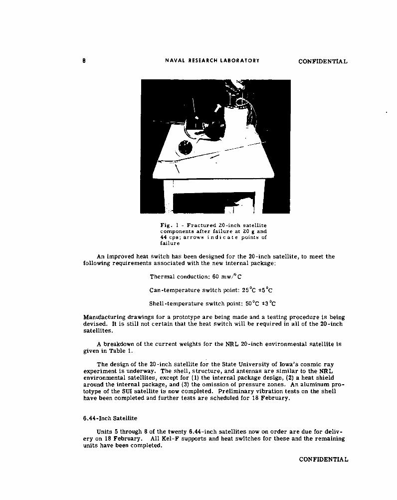
Unit 1 has undergone steady-state accelerations up to 55 g without failure, and furthertesting, up to 70 g, is scheduled. Destructive vibration tests have also been made on thisunit; a systematic increase of acceleration levels through the frequency range from 10 to2000 cps ended in failure at 20 g and 44 cps, which is well over the maximum expectedvibration level. The fractured components are shown in Fig. 1. The base mounting hubon the internal package fatigued as a result of the many reversals of stress at high accel-eration levels. The Kel-F side support fractured simultaneously, as did one of the anten-nas. The internal can contained 10.25 lb of lead-filled modules to simulate the currentweight of the electronics during all tests. At 20 g and 44 cps, this loading would producea 205-pound force which would act up and down at the rate of 44 times per second.
The main base Kel-F support is being reduced in cross section to reduce its thermalconduction. A step-by-step reduction and load test program is underway to give mini-mum cross section with known load-carrying characteristics.
The remaining 18 satellite separation mechanisms are scheduled for delivery on1 March 1957; indications are this date will be met.
CONFIDENTIAL 7
8 NAVAL RESEARCH LABORATORY CONFIDENTIAL
Fig. 1 - Fractured 20-inch satellitecomponents after failure at 20 g and44 cps; arrows indicate points offailure
An improved heat switch has been designed for the 20-inch satellite, to meet thefollowing requirements associated with the new internal package:
Thermal conduction: 60 mw// C
Can-temperature switch point: 25 0C *5°C
Shell-temperature switch point: 50 0 C ±3 °C
Manufacturing drawings for a prototype are being made and a testing procedure is beingdevised. It is still not certain that the heat switch will be required in all of the 20-inchsatellites.
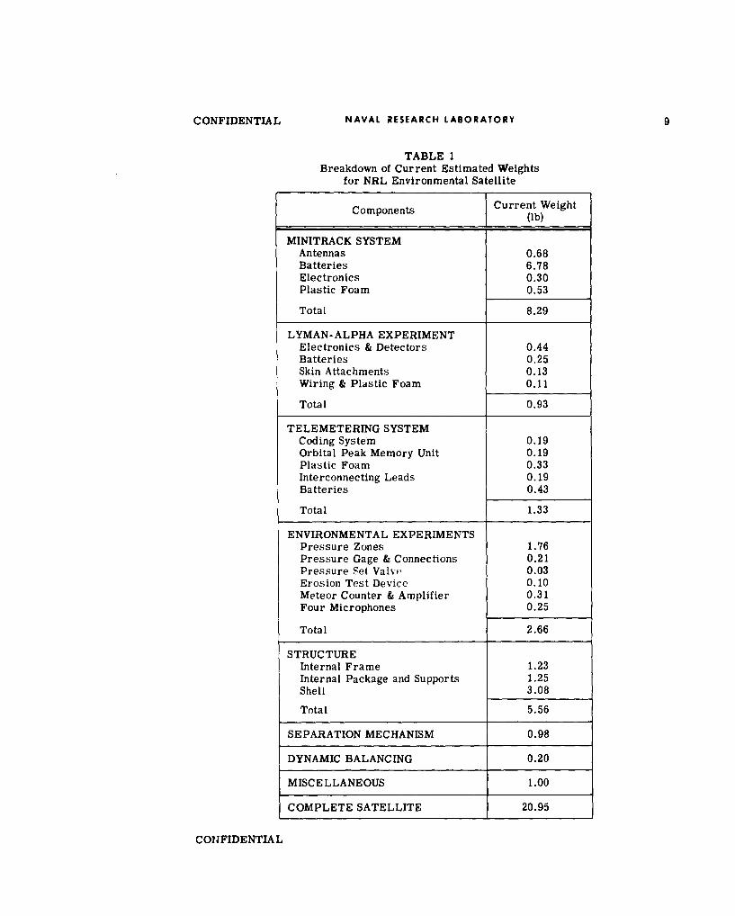
A breakdown of the current weights for the NRL 20-inch environmental satellite isgiven in Table 1.
The design of the 20-inch satellite for the State University of Iowa's cosmic rayexperiment is underway. The shell, structure, and antennas are similar to the NRLenvironmental satellites, except for (1) the internal package design, (2) a heat shieldaround the internal package, and (3) the omission of pressure zones. An aluminum pro-totype of the SUI satellite is now completed. Preliminary vibration tests on the shellhave been completed and further tests are scheduled for 18 February.
6.44-Inch Satellite
Units 5 through 8 of the twenty 6.44-inch satellites now on order are due for deliv-ery on 18 February. All Kel-F supports and heat switches for these and the remainingunits have been completed.
CONFIDENTIAL

8 NAVAL RESEARCH LABORATORY CONFIDENTIAL
Fig. 1 - Fractured 20-inch satellitecomponents after failure at 20 g and44 cps; arrows indicate points offailure
An improved heat switch has been designed for the 20-inch satellite, to meet thefollowing requirements associated with the new internal package:
Thermal conduction: 60 mw/O C
Can-temperature switch point: 250C 5 0C
Shell-temperature switch point: 50 0 C ±3 0 C
Manufacturing drawings for a prototype are being made and a testing procedure is beingdevised. It is still not certain that the heat switch will be required in all of the 20-inchsatellites.
A breakdown of the current weights for the NRL 20-inch environmental satellite isgiven in Table 1.
The design of the 20-inch satellite for the State University of Iowa's cosmic rayexperiment is underway. The shell, structure, and antennas are similar to the NRLenvironmental satellites, except for (1) the internal package design, (2) a heat shieldaround the internal package, and (3) the omission of pressure zones. An aluminum pro-totype of the SUI satellite is now completed. Preliminary vibration tests on the shellhave been completed and further tests are scheduled for 18 February.
6.44-Inch Satellite
Units 5 through 8 of the twenty 6.44-inch satellites now on order are due for deliv-ery on 18 February. All Kel-F supports and heat switches for these and the remainingunits have been completed.
CONFIDENTIAL
CONFIDENTIAL NAVAL RESEARCH LABORATORY 9
TABLE 1Breakdown of Current Estimated Weights
for NRL Environmental Satellite
Components Current Weight
Ie (ib)
MINITRACK SYSTEMAntennas 0.68Batteries 6.78Electronics 0.30Plastic Foam 0.53
Total 8.29
LYMAN-ALPHA EXPERIMENTElectronics & Detectors 0.44Batteries 0.25Skin Attachments 0.13Wiring & Plastic Foam 0.11
Total 0.93
TELEMETERING SYSTEMCoding System 0.19Orbital Peak Memory Unit 0.19Plastic Foam 0.33Interconnecting Leads 0.19Batteries 0.43
Total 1.33
ENVIRONMENTAL EXPERIMENTSPressure Zones 1.76Pressure Gage & Connections 0.21Pressure Set Valve 0.03Erosion Test Device 0.10Meteor Counter & Amplifier 0.31Four Microphones 0.25
Total 2.66
STRUCTUREInternal Frame 1.23Internal Package and Supports 1.25Shell 3.08
Total 5.56
SEPARATION MECHANISM 0.98
DYNAMIC BALANCING 0.20
MISCELLANEOUS 1.00
COMPLETE SATELLITE 20.95
CONFIDENTIAL

10 NAVAL RESEARCH LABORATORY CONFIDENTIAL
A test has been made on unit 4 to determine the amount of vibration transmitted tothe internal electronics for three different means of attachment; (1) unit on separationmechanism dry (actual flight situation), (2) unit on separation mechanism with grease,and (3) unit rigidly attached to table, no separation mechanism. Vibration runs weremade in three mutually perpendicular directions, and the highest transmission occurredwith the rigid attachment; the lowest transmission occurred with the dry separationmechanism.
INSTRUMENTATION
A preliminary systems check has been run on the instrumentation in a completelyassembled NRL environmental satellite. The Lyman-alpha ion chamber was excited froman external source to simulate a solar flare, and resistances were varied in the varioustime channels to produce the effect of surface erosion and temperature change. Theresults were satisfactory. In future tests the antenna will be bypassed, and the trans-mitter will feed directly into the telemetry receiver through a calibrated attenuator.
Some interference was experienced with the amplifier of the meteor collision detec-tor when it was assembled into the satellite telemetering package. Investigation revealedthat the interference had two sources: the gating pulses fed to the magnetic event counter,and rectification of the modulated 108-Mc signal in the first stage of the amplifier.Relocation of signal leads and proper filtering appears to have eliminated the interference.
The first magnetic tape recorder (FR 100) for ground recording of satellite telemetrysignals has been received, and the acceptance test has been completed. Two WatermanPanelscope monitors have been received and subjected to performance tests. Presentefforts are being directed toward the integration of a complete prototype telemetry receiv-ing and recording system. One element of the system, a control console, is beingdesigned to provide a centralized control of all signals to be recorded.
In the SCEL program for development of a solar power supply for application toproject Vanguard, fifteen solar power supplies have been fabricated and delivered to NRLfor testing in Aerobee-Hi rockets.
Design, fabrication, and installation of the camera extension sections of two Aerobee-Hi rockets, to carry the NRL environmental satellite instruments in the forthcoming testsat WSPG, is complete; the structural tests will be completed shortly.
CONFIDENTIAL
CONFIDENTIAL
ELECTRONIC INSTRUMENTATION
TELEMETERING
PPM/AM Systems
The ppm/am telemetering transmitters for TV-3 and backup have been delivered toGLM. Four more transmitters are undergoing final tests by the contractor and are sche-duled for delivery to NRL on 4 March; the delay on these units has been due to defectswhich the Spivey Co. discovered in their stock of 6AQ6 tubes. Two to four more trans-mitters and five rf transmitting heads are scheduled for delivery on 11 March.
The ppm/am calibrators for TV-3 and backup have been delivered to GLM. Eightadditional calibrators have been received at NRL, and six of these have been tested andaccepted; testing of the remaining two is underway.
The Wilkes Precision Instrument Company has delivered twelve video recorder filmmagazines and thirty tape reels. Testing to date indicates that four of the magazines andthirteen reels are unacceptable.
PWM /FM Systems
The new pwm/fm telemetering transmitter package,* incorporating a transistorizedpower supply, has been completed and is undergoing environmental tests. If the unit isentirely acceptable, it will be flown in TV-4. Revised bench checks of the pwm/fm telem-etry systems have been forwarded to the Vanguard Operations Group at AFMTC.
FM FM Systems
The AN,'UKR-5 fm/fm and pwm/fm ground station,t with associated test equipmentsuch as the Heiland recorder, has been set up in hangar C at AFMTC and is being usedfor transmitter checkout and calibration.
The blockhouse fm/fm monitor rack, incorporating receiver, panoramic indicator,and calibration, has been checked out through the rocket wiring in the hangar.
VEHICLE TRACKING
The construction of a C-band AN/DPN-48 radar beacon at Melpar is now nearly com-plete. However, testing and delivery of this unit are contingent on the acquisition of asuitable C-band magnetron.
RANGE SAFETY
A contract has been let with the Connecticut Telephone and Electric Company for pro-duction of the KY-55/ARW transistorized vehicle command signal decoder.
*P.V.R. No. 13, p. 13tP.V.R. No. 8, p. 13
CONFIDENTIAL 11

CONFIDENTIAL
THE MINITRACK SYSTEM
During January, 1957 the contracts for on-site construction work at the Americanstations of the Army Prime-Minitrack station network were awarded under the super-vision of the District Engineer, U. S. Army Engineer District, Jacksonville. The on-siteconstruction work for the Fort Stewart station was advertised for bid on 29 January bythe District Engineer, U. S. Army Engineer District, Savannah, and bids will be opened26 February 1957.
Shipments of government furnished materials to the Latin American stations are nowin process. Astronomic position and azimuth observations have been completed at allsites except Antofagasta, Chile. A first-order geodetic tie was made to the center of theHavana site and work was initiated on first-order geodetic connections at Cotopaxi andAntofagasta. Signal Corps commissioned and enlisted personnel have been assigned tothe Army Map Service for command and operation of the stations and the Vanguard Pro-ject Office has been established at the Army Map Service* with Engineer and Signal com-missioned personnel assigned. This office will coordinate training and the establishmentand operation of communications, telemetering, and tracking, for the six Army PrimeMinitrack stations.
An inspection party is presently enroute to South America to inspect each PrimeMinitrack site with the site contractor. This is necessary at this time to coordinate theoperations of the contractor and NRL with respect to the rf cable installations, the antennamount installations, the antenna assembly, and the equipment arrivals.
Contract operations have been in process at Mayaguana, Grand Turk, and Antigua forseveral weeks. Cable installation will begin at these locations in that order about 1 March;work with cable splicing and installation teams on site will be supplied by the Laboratory.
Station establishment procedures at all stations are being put on the following approxi-mate schedule, where S is the date of the first expected satellite vehicle launching:
S - 14 weeks: Phase I - Start antenna assembly on rails already preparedby site contractor, lay rf cable in ditches and cover ditches,and install calibration and camera shelter. Site team to con-sist of 4 mechanics and 2 engineers from NRL.
S - 9 weeks: Complete Phase I. Start Phase If - Antenna survey andalignment. Site team to consist of one civil engineer andone technician from NRL.
S - 7-' weeks: Complete Phase II. Start Phase III - Equipment arrival.Install Minitrack electronic trailer in place on pad at siteprepared by site contractor, unload all equipment, connectall components of Minitrack and telemetering systems.Site team to consist of permanent operating crew of one
U. S. Army Officer, approximately twelve Army enlistedpersonnel, two contract engineers, and one NRL scientistas Station Technical Director.
*P.V.R. No. 12, p. 1
12 CONFIDENTIAL
CONFIDENTIAL NAVAL RESEARCH LABORATORY 13
S - 6 weeks: Complete Phase III. Start Phase IV - Station alignmentand adjustment, wherein all components of the Minitrackequipment are critically aligned and adjusted and stationelectronics are put in final operating condition. Site teamto consist of three NRL scientists and the permanentoperating crew.
S - 4-2 weeks:Complete Phase IV. Start Phase V -Calibration. Cali-bration airplane and calibration crew arrive to align cali-bration camera, install, align and adjust the calibrationelectronic units and perform complete calibration of entireMinitrack station components usinghigh-flying aircraftwith flashing light against star background. Site team toconsist of two NRL scientists and the permanent field crew.
S - 2-1 weeks: Phase V completed. The station is now assumed to beready for satellite tracking and requires only continuedoperation and daily solar and radio star checks to monitorits operation.
The Minitrack System Training Class is about to begin, with the initial class sche-duled for 4 March. Six classes, each of five weeks duration, are presently scheduled withclass starting dates of 4 March, 25 March, 15 April, 6 May, 27 May, and 10 June. Thefirst three weeks will take place at NRL, using duplicates of actual Minitrack system com-ponents in special training units prepared for this purpose. The last two weeks will takeplace at the Blossom Point Minitrack Test Facility, with one or two days spent at theMinitrack Ground Station Unit contractor's Plant (the Bendix Radio Division, BendixAviation Corporation, Towson, Maryland). All classes are being established with about12 men each, as follows:
Class 1: 6 U. S. Army officers4 U. S. Army technical representatives2 NRL personnel
Class 2: 6 NRL personnel6 unassigned
Class 3: 3 U. S Army Map Service personnel5 U. S. Army enlisted crew for Santiago, Chile station5 U. S. Army enlisted crew for Antofagasta, Chile Station
Class 4: 3 U. S. Army Map Service personnel5 U. S. Army enlisted crew for Lima, Peru station5 U. S. Army enlisted crew for Quito, Ecuador station
Class 5: 3 Australian personnel5 U. S. Army enlisted crew for Havana, Cuba station5 U. S. Army enlisted crew for Fort Stewart, Georgia station
Class 6: 6 NRL personnel6 Navy Electronics Laboratory personnel
CONFIDENTIAL
CONFIDENTIAL
DATA PROCESSING
TELEMETERED DATA
Reduction of the nose-cone telemetered data (ppm/am) from the TV-0 flight has beendelayed; however, the Physical Science Laboratory of the New Mexico College of Agricultureand Mechanic Arts expects to forward preliminary results about the end of February 1957.NRL has now received the pwm/fm data reduced by AFMTC, and the ppm/am and pwm/fmdata reduced by GLM from the vehicle telemetering records for TV-0.
The data recording trailer of the automatic recording and reduction facility (ARRF)*being built by Radiation, Inc. may be sufficiently near completion by the time of the TV-1launching to permit digital recording of the ppm/am data at the NRL Telemetry Pad (CapeCanaveral) for this flight. The pwm/fm and fm/fm portions of the data recording sys-tem should be completed in time for the flight firing of TV-2. Although the interim trans-istorized ppm/am quantizer developed at NRL was ready in February as planned, it hasbeen decided not to deliver the unit to Radiation, Inc. until it is needed, so that furthercircuit improvements can be made. A translator for the pwm/fm ground station has beenmodified at NRL so that its output can be used for encoding and recording by ARRF of all45 channels of pwm/fm data in real time. This translator has been checked by Radiation,Inc. and appears satisfactory.
The linearizer for the digital data reduction system of the ARRF is being built forRadiation Inc. by RCA. This linearizer, a matrix of magnetic cores with transistordrivers, is a digital function table which will serve to eliminate nonlinearities in the tel-emetered data as recorded. A simulator has been built for checking the operation of thesubchannel selector being developed at NRL for the data reduction portion of the ARRF.Work on noise rejection circuits is continuing.
ORBITAL DATA
The final drawings and rendering of the front of the Vanguard Computing Center assubmitted by the International Business Machines Corporation for the building at 615Pennsylvania Avenue, N. W., Washington, D. C., have been approved by the D. C. Com-mission of Fine Arts'. The interior demolition work is nearly completed in preparationfor complete remodeling inside the building. The building contractor will complete hiswork in May and the center will be ready for operation with the IBM 704 computer inJune 1957.
Programming for and test computations on the 704 computer have been continued bythe IBM mathematicians for elliptic orbit determination and prediction from sets of threeand four observations.
THIRD-STAGE FIRING PREDICTION
The Milgo Electronic Corporation submitted the only bid to provide the equipment fortransmitting the digital output of the IBM 704 computer at Cape Canaveral to the third-stage firing control console at Central Control. It is expected that this contract will belet by the RCA Service Company at AFMTC by the end of February 1957 and that theequipment will be delivered 120 days later.
*P.V.R. No. 11, p. 26 14 CONFIDENTIAL
CONFIDENTIAL
RANGE OPERATIONS
The controls functional checks on TV-I in hangar C have been completed. The inver-sion and separation checks encountered some difficulties and are not yet complete; how-ever, completion is expected very shortly. Calibration of the controls functions end organsis complete, and the remaining instrumentation checks must await the arrival of the nosecone.
Delivery of the nose cone is being delayed because of problems of dynamic balancing,antenna testing, and instrument installation; although the additional delay is not expectedto be great, no firm delivery date can be given at this time.
The telemetry ground stations are checked out and ready for the TV-i launching;however, attempts to improve their operation will continue. Some work on the vehiclefm/fm transmitter has been necessary to eliminate noise; this work is progressing satis-factorily. The two ppm/am transmitters and the spare pwm/fm transmitter have beenchecked out and are satisfactory; the flight pwm/fm transmitter is expected to arrive withthe nose cone. Two sets of command receivers have also been tested satisfactorily. Pre-parations are underway to test the AN/DPN-19 radar beacon in an airplane flight, and ablockhouse panel to monitor the operation of this beacon is under construction.
If the nose cone is not delayed more than is now expected, TV-1 will be launched onor about 10 April.
CONFIDENTIAL 15
I I I I
U) U)*0 ~U)Cc4) 4) . 4)co
U0 0 0
.0 co U,4 ) ) U
4) 04 U. W4 04 6-
-~ - .0
0 0. CL
04 Z 'o0 O~~ U-0 U))00
.a JO~~ U) 'a.) -U ~ -4E r ."
)4 0 q M bA W M -, N- mb1L,1
*4r 0 Af.. U)=4)g,"OS o V)u '0 a,-
-- u~ U, L
41 r
a) 4) -
(7 0 7. gW0
0 >0 C w q '
m- : U 4)4. 4
0 >
-L l CL C.
0 ..
- U)m Z l O
ego 0 a>o-C r
0 u
NO W
0 a: 4) - ,1
Le) I )0 W V, ;
FY r-, (7qg--/4 3,1-c VV/
tt7&7 -/t0 3VbY/,c)
Naval Research Laboratory ( 77 -" 1,1 . .J IResearch Reports Library A , 06 3 1,o -755
Code 5596.3 C-/e/5 /- c /
/8 -/) 54~3/3/,5 7
Date: 13 Dec07 //e9O q0 3( 5 o 93,/q0(o -,4 D6 Yl /* 3
From: Judi Griffin code 5596.3 L q / , 0 0 z'¢J 3o ,-A b63Q/ q(f
To: code 8 00 Lq5o " / 3V3CC: Vicki Cicala code 1226.3 '/ 9 - -
Subj: Review of VANGUARD Progress reports for distribution change 3)-b 0- Z 3?SsU,<
Please Review: FR-4717, FR-4728, FR-4748, FR-4767, FR-4800, FR-4815, FR-4832,FR-4860, FR-4880, FR-4890, FR-4900, FR-4910, FR-4930, FR-4950, FR-4995,FR-5010, FR-5020, FR-5035, FR-5050, FR-5113, FR-5185, FR-5217, FR-5227For possible Distribution Statement Change to: APPROVED FOR PUBLIC - - /V 1' J 767RELEASE - DISTRIBUTION UNLIMITED J-/) ,?66 7Thank You S c7 -4)6Q67CoK_Judi Griffin(202) 767-3425 o(Judi. griffingnrl.nvy,mil
The Subject Report(s) can be (please sign after appropriate change):
Changed to Distribution A (Unlimited)
Changed to Classification
Other: