autobench™1 - eembc · at each cylinder firing a ... algorithm flowchart (page 2) an...
TRANSCRIPT

w w w . e e m b c . o r g
software benchmark data book
AutoBench™1.1
An Industry-Standard Benchmark Consortium
EEMBC AutoBench Data Book www.eembc.org 1
Table of Contents
Angle to Time Conversion ............................................................2
Basic Integer and Floating Point ...................................................4
Bit Manipulation .........................................................................5
Cache “Buster” ..........................................................................6
CAN Remote Data Request ..........................................................7
Fast Fourier Transform (FFT) .......................................................9
Finite Impulse Response (FIR) Filter ............................................10
Inverse Fast Fourier Transform (iFFT) .........................................12
Infinite Impulse Response (IIR) Filter ..........................................13
Matrix Arithmetic .....................................................................15
Pointer Chasing ........................................................................16
Pulse Width Modulation (PWM) ...................................................17
Road Speed Calculation .............................................................19
Table Lookup and Interpolation ..................................................21
Tooth to Spark .........................................................................23

An Industry-Standard Benchmark Consortium
EEMBC AutoBench Data Book www.eembc.org 2
AutoBench™ Version 1.1 Benchmark Name: Angle to Time Conversion
Benchmark Description
This EEMBC benchmark simulates an embedded automotive application where the CPU reads a counter which measures the real-time delay between pulses sensed from a toothed wheel (gear) on the crankshaft of an engine. Then the CPU determines the Top Dead Center (TDC) position on the crankshaft, computes the engine speed, and provides a conversion from the tooth wheel pulses to precise crankshaft angle position. This value is expressed in linear time from TDC. The tooth wheel pulses actually represent crankshaft angle, and the delay between pulses yields angular velocity of the crankshaft (engine speed).
The kernel starts each pass of the loop by reading a previous real-time counter value from the test data file. The previous counter value is subtracted from the current counter value to determine the time between teeth edges. As long as the CPU does not detect TDC, the tooth pulse counter is incremented, and indicates progress through a crankshaft revolution. As the tooth pulse counter increments, each cylinder is ‘fired’ in turn once its ‘firing angle’ (tooth number) is reached. At each cylinder firing a precise ‘firing time’ is issued to some external hardware counter. Detection of the next TDC causes the tonewheel tooth counter to be reset to zero, and the entire process begins again.
Optimization Rules
Category Allowed Disallowed
ANSI C X
Intrinsics/Language Extensions
X
Custom Libraries X
Assembly Language
X
HW Accelerators X
Algorithm Flowchart (page 2)

An Industry-Standard Benchmark Consortium
EEMBC AutoBench Data Book www.eembc.org 3
Algorithm Flowchart

An Industry-Standard Benchmark Consortium
EEMBC AutoBench Data Book www.eembc.org 4
AutoBench™ Version 1.1 Benchmark Name: Basic
Integer and Floating Point
Benchmark Description
This EEMBC benchmark algorithm measures basic integer and floating point capabilities.
The benchmark calculates the arctan(x) function using the telescoping series:
arctan(x) = x * P(x^2) / Q(x^2)
where P and Q are polynomials, and x is assumed to be in the range from 0 to tan(pi/4). The benchmark limits the input domain to ensure this condition is met and adjusts any output values which correspond to limited input values so that the correct result is always obtained.
Optimization Rules
Category Allowed Disallowed
ANSI C X
Intrinsics/Language Extensions X
Custom Libraries X
Assembly Language
X
HW Accelerators X
Algorithm Flowchart

An Industry-Standard Benchmark Consortium
EEMBC AutoBench Data Book www.eembc.org 5
AutoBench™ Version 1.1 Benchmark Name: Bit
Manipulation
Benchmark Description
This EEMBC benchmark simulates an embedded automotive/industrial application where large numbers of bits have to be manipulated, many decisions have to be taken based upon bit values and bit arithmetic takes place.
The kernel simulates part of a character display system where characters are shifted into a line buffer. The line buffer is then converted into a series of pixels by mapping characters through a display character ROM. The pixels are moved into a display buffer until the entire buffer is displayed.
Optimization Rules
Category Allowed Disallowed
ANSI C X
Intrinsics/Language Extensions
X
Custom Libraries X
Assembly Language
X
HW Accelerators X
Algorithm Flowchart

An Industry-Standard Benchmark Consortium
EEMBC AutoBench Data Book www.eembc.org 6
AutoBench™ Version 1.1 Benchmark Name: Cache
“Buster”
Benchmark Description
This EEMBC benchmark simulates an embedded automotive/industrial application without a cache. It highlights performance in those situations when long sections of control code are executed with very little backwards branching or revisiting of the same data. Processors which utilize look ahead mechanisms rather than caches should perform well here.
The kernel uses an intricate algorithm involving data and function pointers to ensure that data and code locality does not occur during execution.
Optimization Rules
Category Allowed Disallowed
ANSI C X
Intrinsics/Language Extensions
X
Custom Libraries X
Assembly Language
X
HW Accelerators X
Algorithm Flowchart

An Industry-Standard Benchmark Consortium
EEMBC AutoBench Data Book www.eembc.org 7
AutoBench™ Version 1.1 Benchmark Name: CAN Remote Data Request
Benchmark Description
This EEMBC benchmark simulates an embedded automotive application where a Controller Area Network (CAN) interface node exists for exchanging messages across the system.
The situation being simulated is that which occurs when a Remote Data Request (RDR) message is received by all nodes. Every node must check the identifier of the message to see if they own that type of data. If yes, then the responsible node must gather the data and transmit it back onto the network for the originator of the RDR.
The kernel fetches received messages from a simulated receiver buffer, checks the identification (ID) field and ignores those messages which it is not interested in. Interesting messages are then usually stored, unless they are a RDR message,. In this case the data associated with the ID is sought and then placed into a simulated transmit buffer for sending back to the originator.
Optimization Rules
Category Allowed Disallowed
ANSI C X
Intrinsics/Language Extensions
X
Custom Libraries X
Assembly Language
X
HW Accelerators X
Algorithm Flowchart (page 7)

An Industry-Standard Benchmark Consortium
EEMBC AutoBench Data Book www.eembc.org 8
Algorithm Flowchart

An Industry-Standard Benchmark Consortium
EEMBC AutoBench Data Book www.eembc.org 9
AutoBench™ Version 1.1 Benchmark Name: Fast
Fourier Transform (FFT)
Benchmark Description
This EEMBC benchmark simulates an embedded automotive/industrial application performing a power spectrum analysis of a time varying input waveform.
The kernel computes the ‘radix-2’ decimation in frequency Fast Fourier Transform (FFT) on complex input values stored in real and imaginary arrays. After the time domain values are converted to the equivalent frequency domain, the power spectrum is calculated.
Optimization Rules
Category Allowed Disallowed
ANSI C X
Intrinsics/Language Extensions
X
Custom Libraries X
Assembly Language
X
HW Accelerators X
Algorithm Flowchart

An Industry-Standard Benchmark Consortium
EEMBC AutoBench Data Book www.eembc.org 10
AutoBench™ Version 1.1 Benchmark Name: Finite Impulse Response (FIR) Filter
Benchmark Description
This EEMBC benchmark algorithm simulates an embedded automotive/industrial application where the CPU performs a Finite Impulse Response (FIR) filtering sample on 16-bit or 32-bit fixed-point values. High- and low-pass FIR filters simply process the input signal data.
Optimization Rules
Category Allowed Disallowed
ANSI C X
Intrinsics/Language Extensions
X
Custom Libraries X
Assembly Language
X
HW Accelerators X
Algorithm Flowchart
An Industry-Standard Benchmark Consortium
EEMBC AutoBench Data Book www.eembc.org 11
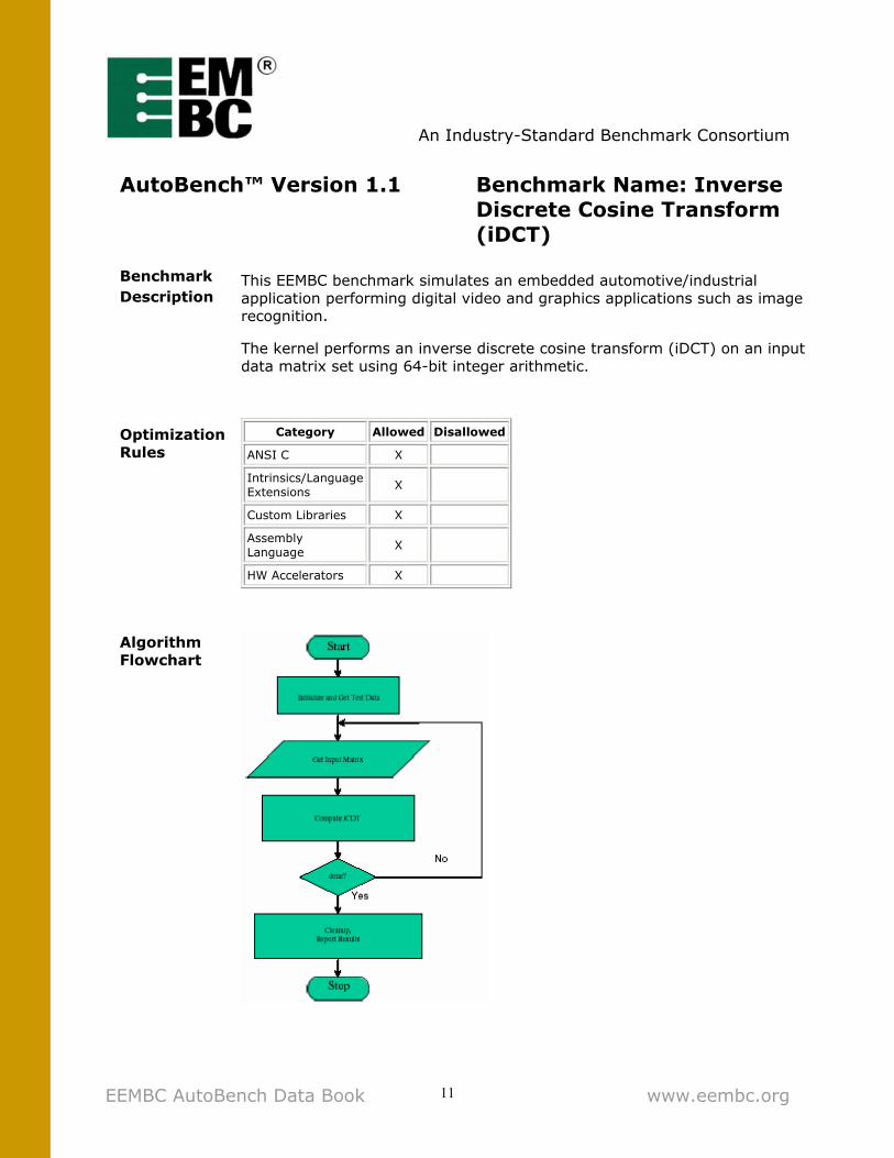
AutoBench™ Version 1.1 Benchmark Name: Inverse Discrete Cosine Transform (iDCT)
Benchmark Description
This EEMBC benchmark simulates an embedded automotive/industrial application performing digital video and graphics applications such as image recognition.
The kernel performs an inverse discrete cosine transform (iDCT) on an input data matrix set using 64-bit integer arithmetic.
Optimization Rules
Category Allowed Disallowed
ANSI C X
Intrinsics/Language Extensions
X
Custom Libraries X
Assembly Language
X
HW Accelerators X
Algorithm Flowchart

An Industry-Standard Benchmark Consortium
EEMBC AutoBench Data Book www.eembc.org 12
Automotive/Industrial Subcommittee
Benchmark Name: Inverse Fast Fourier Transform (iFFT)
Benchmark Description
This EEMBC benchmark simulates an embedded automotive/industrial application analysis of a time domain analysis of an input frequency spectrum. This might be used in noise cancellation applications.
The kernel computes the ‘radix-2’ decimation in frequency inverse Fast Fourier Transform (FFT) on complex input values stored in real and imaginary arrays.
Optimization Rules
Category Allowed Disallowed
ANSI C X
Intrinsics/Language Extensions
X
Custom Libraries X
Assembly Language
X
HW Accelerators X
Algorithm Flowchart
An Industry-Standard Benchmark Consortium
EEMBC AutoBench Data Book www.eembc.org 13
AutoBench™ Version 1.1 Benchmark Name: Infinite Impulse Response (IIR) Filter
Benchmark Description
This Embedded Microprocessor Benchmark Consortium (EEMBC) benchmark algorithm simulates an embedded automotive/industrial application where the CPU performs an Infinite Impulse Response (IIR) filtering sample on 16-bit or 32-bit fixed-point values. It implements a Direct-Form II N-cascaded, second-order IIR filter. IIR filters can often be more efficient that FIR filters, in terms of attaining better magnitude response with a given filter order. This is because IIR filters incorporate feedback and are capable of realizing both poles and zeros of a system, whereas FIR filters are not capable of realizing the zeros. The difference equation for a Direct Form II N-Cascaded Direct second-order IIR filter is:
{u(n) = x(n) + a(1)*x(n-1) + a(2)*x(n-2), {y(n) = b(0)*u(n) + b(1)*u(n-1) + b(2)*u(n-2);
where: x(n) = input signal of the biquad at time n u(n) = state variable of the biquad at time n y(n) = output signal of the biquad at time n a(n), b(n) = coefficients of the biquad
High- and low-pass IIR filters process the input signal data. Binary comparators also digitize the outputs of the filters. This IIR filter benchmark explores a CPU’s ability to perform multiply-accumulates and rounding. It employs typical DSP functions that would replace an analog signal chain comprised of op-amps and comparators.
Optimization Rules
Category Allowed Disallowed
ANSI C X
Intrinsics/Language Extensions
X
Custom Libraries X
Assembly Language
X
HW Accelerators X
Algorithm Flowchart (page 13)

An Industry-Standard Benchmark Consortium
EEMBC AutoBench Data Book www.eembc.org 14
Algorithm Flowchart

An Industry-Standard Benchmark Consortium
EEMBC AutoBench Data Book www.eembc.org 15
AutoBench™ Version 1.1 Benchmark Name: Matrix
Arithmetic
Benchmark Description
This EEMBC benchmark simulates an embedded automotive/industrial application which performs a lot of matrix arithmetic.
The kernel performs an LU decomposition on ‘n x n’ input matrices. It also computes the determinant of the input matrix then a cross product with a second matrix.
Optimization Rules
Category Allowed Disallowed
ANSI C X
Intrinsics/Language Extensions
X
Custom Libraries X
Assembly Language
X
HW Accelerators X
Algorithm Flowchart

An Industry-Standard Benchmark Consortium
EEMBC AutoBench Data Book www.eembc.org 16
AutoBench™ Version 1.1 Benchmark Name: Pointer
Chasing
Benchmark Description
This EEMBC benchmark simulates an embedded automotive/industrial application which performs a lot of pointer manipulation.
The kernel employs a doubly linked list then searches the list for entries which match an input token. A large set of input tokens is used to exercise the entire list. The number of steps taken to find each input token is recorded.
Optimization Rules
Category Allowed Disallowed
ANSI C X
Intrinsics/Language Extensions
X
Custom Libraries X
Assembly Language
X
HW Accelerators X
Algorithm Flowchart

An Industry-Standard Benchmark Consortium
EEMBC AutoBench Data Book www.eembc.org 17
AutoBench™ Version 1.1 Benchmark Name: Pulse Width Modulation (PWM)
Benchmark Description
This EEMBC benchmark simulates an application in which an actuator is driven by a PWM signal proportional to some input. Specifically, the algorithm presumes that the embedded processor is driving an H-bridge motor driver with both direction and enable signals. Outputs are provided for two such H-bridge drivers, as might be used for a bipolar stepper motor driver, or proportional DC motor driver.
The stepper motor is controlling the position of the actuator. We can control it by passing a desired position command to the algorithm, and let the algorithm control moving the motor to that position.
On each pass, the algorithm simulates the PWM signals and checks to see if the motor has reached the commanded position once per PWM cycle. By providing the stepper motor with phasing signals as well as PWM control of each phase, the motor can be micro-stepped to provide finer resolution and smoother motion. The phase control provides direction signals for energizing each of the stepper motor coils in a typical bipolar full-step sequence. The algorithm could be used in applications with actuators other than stepper motors, making use of just the PWM feature without the phasing control, in which case the PWM signals would provide proportional velocity control, while the phase signals would provide motor direction.
Optimization Rules
Category Allowed Disallowed
ANSI C X
Intrinsics/Language Extensions
X
Custom Libraries X
Assembly Language
X
HW Accelerators X
Algorithm Flowchart (page 17)

An Industry-Standard Benchmark Consortium
EEMBC AutoBench Data Book www.eembc.org 18
Algorithm Flowchart

An Industry-Standard Benchmark Consortium
EEMBC AutoBench Data Book www.eembc.org 19
AutoBench™ Version 1.1 Benchmark Name: Road
Speed Calculation
Benchmark Description
This EEMBC benchmark simulates an automotive application where the CPU repeatedly calculates the road speed based on differences between timer counter values. All values are filtered to minimize errors due to noise. The calculation involves straight-forward arithmetic, but must also deal with the situation when the timer counter rolls over; or when the measurement results show abrupt changes. At zero road speed, the application has to ensure that it does not infinitely wait for a counter increment.
The benchmark has a mix of arithmetic and flow control routines. The arithmetic portion involves add, subtract, multiply and divide. For low end microcontrollers, the arithmetic capability may become a performance bottleneck. For higher end processors, the pipeline efficiency may be more important than raw performance since there are a significant number of compare and branch instructions (i.e. flow control). A processor that is good in both aspects will shine with this kind of benchmark.
Optimization Rules
Category Allowed Disallowed
ANSI C X
Intrinsics/Language Extensions
X
Custom Libraries X
Assembly Language
X
HW Accelerators X
Algorithm Flowchart (page 19)

An Industry-Standard Benchmark Consortium
EEMBC AutoBench Data Book www.eembc.org 20
Algorithm Flowchart

An Industry-Standard Benchmark Consortium
EEMBC AutoBench Data Book www.eembc.org 21
AutoBench™ Version 1.1 Benchmark Name:
Table Lookup and Interpolation
Benchmark Description
This EEMBC benchmark algorithm is used in engine controllers, anti-lock brake systems, and other applications to access constant data quicker than by raw calculation. Instead of storing all data points, which would consume a lot of memory, selective data points are stored and the software then interpolates between them. Data may be stored in 2 dimensional (X,Y) or 3 dimensional (X,Y,Z) tables.
For example, software periodically performs a table lookup process to derive an output value Ignition Angle from two input variables, Engine Load and Engine Speed. The engine control continuously derives the input variables, Load and Speed, from external engine sensors. Speed is derived by measuring the period between pulses from magnetic pickup sensing gear teeth on the crankshaft. Load is derived from sensors measuring air flow through the throttle body.
The bilinear interpolation technique determines values by using four points in a grid that surrounds the desired point.
This algorithm simulates engine load and speed which are indices into an “angle” table. The engine load (X) and engine speed (Y) values are calculated and normalized. The ignition angle (Z) value is then interpolated from the table.
Optimization Rules
Category Allowed Disallowed
ANSI C X
Intrinsics/Language Extensions
X
Custom Libraries X
Assembly Language
X
HW Accelerators X
Algorithm Flowchart (page 21)

An Industry-Standard Benchmark Consortium
EEMBC AutoBench Data Book www.eembc.org 22
Algorithm Flowchart

An Industry-Standard Benchmark Consortium
EEMBC AutoBench Data Book www.eembc.org 23
AutoBench™ Version 1.1 Benchmark Name: Tooth to
Spark
Benchmark Description
This EEMBC benchmark simulates an automotive application where the CPU controls fuel injection and ignition in the engine combustion process. Tooth-to-Spark, part of an Engine Control Unit (ECU), performs real-time processing of air/fuel mixture and ignition timing. Based on the operating conditions presented to the ECU, the CPU adjusts the output values for fuel injector duration and ignition timing from ‘nominal’ values on each pass.
The ECU determines whether the engine is running or not, and enables the fuel pump and igniters accordingly. While the engine is being started, the ECU performs special fuel injection duration and spark timing to optimize starting conditions.
Once the engine is running, the CPU processes the output variables for injector and igniter timing on each pass. The CPU primarily makes adjustments according to the engine speed/load parameters, but also makes lesser adjustments for other variables.
The entire process is repeated on each pass, taking input values from the test data and computing new output values. The input test data can reside in ROM or RAM, so comparisons can be made for performance from either memory source.
Optimization Rules
Category Allowed Disallowed
ANSI C X
Intrinsics/Language Extensions
X
Custom Libraries X
Assembly Language
X
HW Accelerators X
Algorithm Flowchart (page 23)

An Industry-Standard Benchmark Consortium
EEMBC AutoBench Data Book www.eembc.org 24
Algorithm Flowchart