autocad 2006 tips n tricks - · pdf fileselect the arrow down key to display any command...
TRANSCRIPT
Palettes
User Interface
Sheet Sets
Lynn Allen’s
Tips &Tricks for Using AutoCAD® 2006 Software
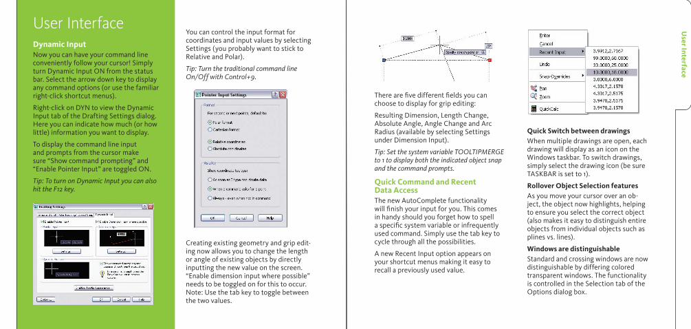
User InterfaceDynamic InputNow you can have your command line conveniently follow your cursor! Simply turn Dynamic Input ON from the status bar. Select the arrow down key to display any command options (or use the familiar right-click shortcut menus).
Right-click on DYN to view the Dynamic Input tab of the Drafting Settings dialog. Here you can indicate how much (or how little) information you want to display.
To display the command line input and prompts from the cursor make sure “Show command prompting” and “Enable Pointer Input” are toggled ON.
Tip: To turn on Dynamic Input you can also hit the F12 key.
User Interface
You can control the input format for coordinates and input values by selecting Settings (you probably want to stick to Relative and Polar).
Tip: Turn the traditional command line On/Off with Control+9.
Creating existing geometry and grip edit-ing now allows you to change the length or angle of existing objects by directly inputting the new value on the screen. “Enable dimension input where possible” needs to be toggled on for this to occur. Note: Use the tab key to toggle between the two values.
There are five different fields you can choose to display for grip editing:
Resulting Dimension, Length Change, Absolute Angle, Angle Change and Arc Radius (available by selecting Settings under Dimension Input).
Tip: Set the system variable TOOLTIPMERGE to 1 to display both the indicated object snap and the command prompts.
Quick Command and Recent Data AccessThe new AutoComplete functionality will finish your input for you. This comes in handy should you forget how to spell a specific system variable or infrequently used command. Simply use the tab key to cycle through all the possibilities.
A new Recent Input option appears on your shortcut menus making it easy to recall a previously used value.
Quick Switch between drawingsWhen multiple drawings are open, each drawing will display as an icon on the Windows taskbar. To switch drawings, simply select the drawing icon (be sure TASKBAR is set to 1).
Rollover Object Selection featuresAs you move your cursor over an ob-ject, the object now highlights, helping to ensure you select the correct object (also makes it easy to distinguish entire objects from individual objects such as plines vs. lines).
Windows are distinguishableStandard and crossing windows are now distinguishable by differing colored transparent windows. The functionality is controlled in the Selection tab of the Options dialog box.

Palettes
Customizing the Tool palette using DesignCenter1. Display Tool palette by pressing Ctrl+3
or by selecting from the Tools menu.
2. Open the DesignCenterTM utility and drag blocks, xrefs, images, and hatch patterns one by one to the Tool palette. Or right-click on any drawing name in DesignCenter to create a new tab that contains all the content within the draw-ing.
Creating Tools from existing objects1. Select the object.
2. Drag and drop the object onto the palette using the right mouse button (the tool will land where the black line is displayed).
3. The command, properties, and style (where applicable) are now accessible from the palette (great for dimensions, text, and so on).
Creating a palette tool from existing toolbars1. Right-click on the Tool palette title bar
and select Customize.
2. Drag and drop the desired command from any existing toolbar button.
Additional Tool palette features1. Right-click on any tool and select
Properties from the shortcut menu to set up the various parameters such as layer, scale factor, and so on, for each tool.
2. Control the transparency of the Tool palette by right-clicking on the palette (not on a tool) and selecting Transpar-ency from the shortcut menu.
3. Control the display and size of the icons by selecting View Options from the shortcut menu (set to Icon Only to display more tools).
4. Save your tool palettes to disk as an XTP file for others to import using the CUSTOMIZE command (right-click to find export/import in the shortcut menu). You can also organize your tool palettes into specific groups for faster access and organizational purposes.
5. When inserting a block, you can change the scale and rotation angle from a shortcut menu.
6. You can also set the scale factor to DIMSCALE or PLOTSCALE by selecting Auxiliary scale factor in Properties (great way to set up a block or hatch pattern that automatically scales).
7. AutoCAD® 2006 allows you to edit the properties of multiple tools at a time!
8. Add separator bars and descriptive text to help guide the user through task-based processes.
Tip: Use Tool palettes to quickly place dimensions or text of a specific style. Drag a dimension/text string onto the Tool palette; name it after the corresponding style.
Locking Toolbars and Tool palettes in placeIf you have all your toolbars and palettes right where you want them—lock them up! Right-click on the lock at the end of the status bar and select what you want to lock from the shortcut menu. Use the Control key to temporarily override locking.
PalettesTool PalettesTool palettes can be customized to contain your most frequently used blocks, hatch patterns, images, solid and gradient fills, macros (including LISP and ARX routines), and command tools. These become even more powerful when you assign specific properties such as layer, scale factor, rotation angle, and so on, to each tool. (Fantastic for hatch patterns!)
Pal
ette
s
Sheet Sets
Sheet SetsSheet sets were added to AutoCAD® 2005 to help you better organize your drawing files. You can combine the sheets in any order, even group them into subsets. Sheet sets make it easy to publish, archive, and eTransmit your project files.
Sheet Set Basics• Each drawing sheet points to one layout.
• You can create several sheets from a drawing with multiple layouts.
• It’s easy to add, remove, and renumber each sheet.
• Though the drawing files may come from many different locations, the Sheet Set Manager will keep track of them all for you.
• Multiple users can access and edit a sheet set at the same time, but only one user can edit the same sheet.
• Each drawing can belong to only one sheet set.
Creating a Sheet Set1. Open a drawing file.
2. Access the Sheet Set Manager (SSM) from the Tools menu or by pressing Ctrl+4.
3. Select New Sheet Set from the Files menu or from the Sheet Set Manager drop-down list.
4. This will take you to the Create Sheet Set wizard.
Use the Create Sheet Set wizard to set up the parameters for your new sheet set. Here you will:
• Choose to use an existing sheet set as an example, or define your own from exist-ing drawings.
• Choose the name and location for your new sheet set (extension of .dst).
• Assign any specific properties such as template file, callout block, and so on.
Open a sheet by a simple double-click.
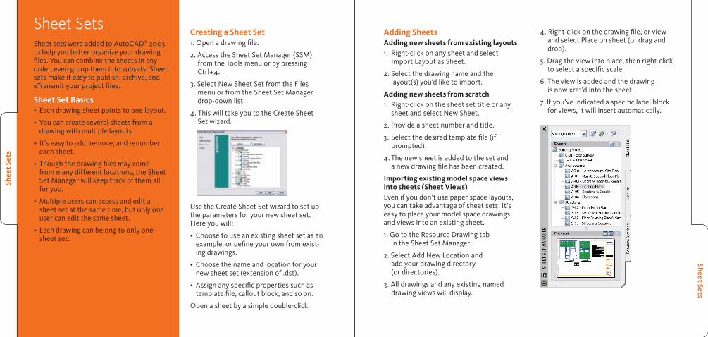
Adding SheetsAdding new sheets from existing layouts1. Right-click on any sheet and select
Import Layout as Sheet.
2. Select the drawing name and the layout(s) you’d like to import.
Adding new sheets from scratch1. Right-click on the sheet set title or any
sheet and select New Sheet.
2. Provide a sheet number and title.
3. Select the desired template file (if prompted).
4. The new sheet is added to the set and a new drawing file has been created.
Importing existing model space views into sheets (Sheet Views)Even if you don’t use paper space layouts, you can take advantage of sheet sets. It’s easy to place your model space drawings and views into an existing sheet.
1. Go to the Resource Drawing tab in the Sheet Set Manager.
2. Select Add New Location and add your drawing directory (or directories).
3. All drawings and any existing named drawing views will display.
4. Right-click on the drawing file, or view and select Place on sheet (or drag and drop).
5. Drag the view into place, then right-click to select a specific scale.
6. The view is added and the drawing is now xref’d into the sheet.
7. If you’ve indicated a specific label block for views, it will insert automatically.
Shee
t Set
s

Sheet SetsShee
t Set
s
Sheet ViewsUse the Sheet Views tab to:
• Rename and renumber your sheet views.
• Add a view label or callout block to a sheet.
• Group the sheet views into categories and assign different callout blocks to each view category.
Tip: As you go forward with your drawings and sheet sets, you might find it useful to restrict each drawing file to one layout—since only one person can edit a drawing at a given time.
Organizing SheetsYou can reorder, rename, and remove any of your existing sheets using the sheet set shortcut menu.
You can also create subsets of sheets for further organization purposes.
You can save a set of named sheets for speedy access.
Note: Removing a sheet does not delete the DWG file.
Creating a Sheet IndexAutoCAD 2005 and AutoCAD 2006 will now automatically create a sheet table. You can quickly go to any sheet listed in the table by clicking the hyperlinked sheet name.
1. Right-click the title sheet and select Insert Sheet List Table.
2. Indicate a table style.
3. Place the sheet list table in the drawing.
Updating the Sheet List IndexRight-click on the table and select Update Sheet List Table from the shortcut menu.
New to AutoCAD 2006Since Sheet Sets were introduced in AutoCAD 2005, users have submitted wishlist items for fine-tuning sheet sets. Below is a list of these enhancements:
1. You can open or import multiple sheets.
2. Creating a new subset can create a correlating folder.
3. Renaming a sheet now has the option of renaming the drawing file.
4. New icons indicate if a sheet is locked (in use) or missing.
5. You can open a sheet as read-only.
6. Callout and label blocks now display a preview image.
7. The View list can be sorted by view category or by sheet name.
8. Views can now be saved by sheet (less confusing).

Tables
Tables No more drawing grids by hand! AutoCAD 2005 and AutoCAD 2006 have a new intelligent TABLE object that will eliminate a lot of tedium and save you time.
Creating TablesJust as you do with dimensions and text, you first set up your table style in the Table Style dialog box.
1. Select Tablestyle from the Format menu.
2. Select New to create a new table style.
3. Set up your table style to reflect your needs, such as table direction, text height, alignment, border properties, and so on.
Now you’re ready to create your table1. Select Table from the Draw menu.
2. Select your table style.
3. Indicate the number of rows and columns.
4. Input specific column width and row height, or let AutoCAD determine it by the table size.
Populating tablesIn-place editing makes it easy to fill in the cells.
• The Tab and arrow keys move across cells.
• Double-click a table cell to enter text using the MTEXT editor.
• You can also insert fields and symbols from the shortcut menu.
• Clicking in a table cell permits you to insert a block from the shortcut menu.
You can let AutoCAD software fit the block in the cell or specify a scale factor and the table will adapt accordingly.
• Clicking also allows you to merge cells, add and delete rows, and so forth. You can use grips to modify the table loca-tion, column width, and row height.
Accessing tables from Excel1. Copy Excel table data to the clipboard.
2. Select Paste Special from the Edit menu.
3. Select AutoCAD Entities.
4. Place the table in your drawing.
5. Formulas will also come across in AutoCAD 2006.
Exporting AutoCAD tablesThe TABLEEXPORT command will save an AutoCAD table out to a comma separated value (CSV). This file can easily be taken into Excel or Access.
Extracting Block Attribute Data to a Table1. Execute the Attribute Extraction Wizard
(EATTEXT).
2. Indicate which blocks to extract.
3. Select the attribute information to extract.
4. Preview the table, reorganize columns by dragging the headers. The right-click menu allows you to sort by ascending or descending.
5. Select “AutoCAD table” as the output.
The information in the table is linked to the attribute data and is updateable.
Performing Calculations on Table DataYou can apply simple numeric operations such as Sum, Average, and Count; create arithmetic expressions; and set cells equal to other cells. Select Insert Formula from the shortcut menu.
Tabl
es

Step Savers
IMAGEFRAMESet IMAGEFRAME to 2 to display but not plot the frame.
XREF Notification simplifiedA simple click on Reload Modified Xrefs saves you time.
Object Snap updates• The new object snap “Mid between 2
points” eliminates the need to otherwise create those construction lines. Access it from the right-click OSNAP menu or by keying in M2P or MTP.
• OSNAPZ variable lets you replace the Z value of an OSNAP point with the current elevation (also available in Options).
Rectangle The Rectangle command has two new options:
• Area option where you define the length of one side and then total area
• Rotate option
New Join commandCombines individual segments of like objects into a single object. The objects do not have to meet. You can also use Join to combine lines and arcs with plines (same as PEDIT). Join works on plines, lines, arcs, elliptical arcs and splines.
More flexible MLINESTrim and Extend now work on MLINES.
Zoom improvements• Quickly zoom to the extents of one
or more objects by selecting the new Object option in the ZOOM command.
• New Smooth Transition Zoom makes it easy to maintain orientation (system variable VTENABLE).
• Undo/Redo combines multiple pans and zooms (Options dialog box).
Step SaversUpdates to popular editing commandsUndo options have been added to Copy, Offset, Fillet, Chamfer, Trim, and Extend.
Trim and Extend• New Select All default to select all visible
objects as cutting/boundary edges.
• Crossing/Fence options added as object selections options for the objects to trim/extend.
• Erase Option in Trim so you can also erase those extra objects along the way.
Stretch command • Now supports multiple crossing windows
and standard object selection.
• Only those objects selected with a crossing window or crossing polygon will physically be stretched; all other objects will be moved.
Fillet and ChamferIf you just want to trim corners, you can now use the Shift key to force a Zero radius or distance, which is handy! Select the first object, then hold down the Shift key to select the second object.
Offset • Allows you to erase the source object.
• You can specify whether the new object is created on the current layer or the same layer as the source object.
• New Multiple option lets you continue offsetting a specific distance (no need to reselect a source object).
Rotate and Scale• A new Copy option allows you to create a
copy while you rotate or scale an object.
• The last rotation angle or scale value is available as a default.
• You can now pick any two points to specify a new angle or scale (no longer limited to the basepoint being one of the reference points).
Customizable Scale ListUse the new SCALELISTEDIT command to add/delete, edit and rearrange the scale list used in PLOT, PAGESETUP, Viewport toolbar, and so on.
FIND commandFIND now permits wildcards!
Step
Sav
ers

• You can edit individual components of a block. You can even assign specific increments for stretching or rotating with minimum and maximum values.
• You can create blocks with multiple insertion points.
Defining Dynamic BlocksThe new Block Definition Editor (BEDIT) makes it easy to create dynamic blocks or edit your existing blocks.
1. Select an existing block.
2. Right-click and select Block Editor from the shortcut menu.
The Block Authoring Palettes contain the tools to make your blocks dynamic. The process looks like this:
1. Select a Parameter and assign it to a portion of your block.
Dynam
ic Blocks
Dynamic BlocksThe new Dynamic Blocks allows you to create powerful and flexible blocks like we’ve never had before. Some of the many advantages are:
• One block, multiple definitions that could drastically reduce the size of your block libraries. For example, one bed block, many options.
• Create blocks that automatically align with existing geometry.
2. Select the action you wish to assign to that parameter. Place the Action some-where near the parameter.
3. Most Parameters must have at least one Action.
Tip: Try one parameter/action pair at a time to ensure you are getting the proper results.
ParametersThink of parameters as dimensions that drive the block geometry. Examples include:
• Linear parameter to a door block to drive the width of a door (combine with Stretch Action).
• Rotation parameter to a chair of a table and chairs block permits individual rota-tion of the chair after insertion (combine with Rotate Action).
• Selecting the Properties of a parameter allow you to specify increments as well as minimum/maximum values.
• Visibility Parameters are used to assign multiple definitions to one block. Lookup Parameters might be used to assign mul-tiple sizes of a specific block. A simple right-click allows the user to change from one size to another.
ActionsActions drive the geometry in specific ways. Use Stretch to change the length of a bolt.
Note: An exclamation point will display to indicate any parameters with no assigned action.
Finish by closing the block editor and trying out your new dynamic block!
Dyn
amic
Blo
cks

Productivity Tips
Productivity TipsQuickcalc: a handy calculator!Derived from the Geometric Calculator command (CAL), you can:
• Perform a full range of calculations.
• Convert from one system of units to another.
• Use the Scientific panel for more advanced functions.
• Pass values back and forth to a Command or the Properties Palette.
• Set Variables for use across AutoCAD drawings and sessions.
• Access quickly by keying in QC or Ctrl + 8.
Maximize a ViewportWhile in a paper space layout, you can automatically maximize a layout to work on your model space drawing, using the entire drawing area. Doing so will not modify the scale factor or change the layer settings in any way.
1. Select the viewport.
2. Click the Maximize Viewport button on the status bar.
3. After editing, simply hit the Minimize Viewport button.
Note: Double-clicking on a viewport also maximizes it.
Draworder Step Savers• No more regenerating your drawing
to see the results of the DRAWORDER command.
• If you create a new object based on an existing one, the DRAWORDER proper-ties are also inherited (including copy, fillet, explode, and so on).
Layer TipsNew layer filter warningWhen you have more than 100 named layer filters, the new system variable LAYERFILTERALERT warns you and offers to help you delete any unwanted ones with a dialog box.
Layer properties manager
• Right-click on a column heading to maximize the column.
• Click the new Apply button to immediately apply layer changes.
• Added column for layer description.
• The new Status column displays whether a layer is current, used, or unused.
• Filters are added to control the list of layers that display in the Layer Properties Manager.
• The new Filter Tree view displays existing filters.
• Xref layers are automatically filtered.
Note: Selecting the “Indicate Layers in use” option could dramatically slow down the dialog box.
Property filtersAs you did with the previous Named layer filter dialog box, you have the ability to filter out any layer property such as visibility, color, name, and so on.
1. Select the New Property Filter icon.
2. Name the new filter list.
3. Indicate the desired filters.
4. The list provides a preview update as you assign filters.
5. When finished, the new filter appears in the Filter Tree view for quick access.
Group filtersIt’s easy to divide layers into specific layer categories:
1. Select the New Group Filter icon.
2. Name the new filter.
3. Display all layers by clicking on All.
4. Drag and drop the layers you want to be added to the new filter, or choose Select Layers>Add from the shortcut menu to select objects from the drawing. AutoCAD adds the object layers to the group.
Pro
duct
ivit
y Ti
ps

Custom
ization
CustomizationNow you can customize your AutoCAD application with the new, friendly CUI command. The old menu files (MNU, MNS and MNC) are out—the new XML-based CUI is in!
Migrate existing menu filesIt’s easy to migrate your existing menu files to the new CUI format using the Transfer tab in the CUI command.
Use the Customize tab to modify pull-down menus, toolbars, keyboard shortcuts, shortcut menus, and input device buttons. This friendly drag-and-drop system makes it easy to personalize AutoCAD to your individual needs.
Basic menu syntax; Enter
/ Pause for user input
^C^C Cancel (to make sure you’re at the command prompt)
* Repeats a menu macro
Temporary overridesNow you can override a particular setting with a specific combination of keys. For example, holding down the Shift key down toggles Orthomode on and off. Very handy! Below are just a few examples—you can use these or set up your own. There are even settings for right- and left-handed users!
Shift+A toggle object snap mode
Shift+E turns on endpoint osnap only
Shift+M turns on midpoint osnap only
Shift+C turns on center osnap only
Shift+Q toggles Object Tracking
Shift+X toggles Polar Mode
Workspaces Now you can store workspaces for the different ways you choose to work. For example, you might like your UI for paper space to be set up differently than model space.
Workspaces control the display of toolbars, menus, all tool and command palettes, and the command line.
FieldsFields are equivalent to “smart text” that updates automatically. Use field data for such things as dates, sheet numbers, titles, and so on. Fields can work across sheet sets to update all instances.
Inserting fieldsSelect fields from a list of predefined fields. These fields can be inserted into text objects, attributes, or table cells.
There are three methods for inserting a field:1. Select Insert Field in the shortcut menu
when prompted for text in MTEXT, DTEXT, ATTDEF, and BATTMAN. Some of these commands also have an “insert field” button.
2. Press Ctrl+F.
3. Execute the Field command (this will place the field as MTEXT).
Whichever route you take, simply select the field you wish to add. The FIELD- DISPLAY system variable toggles the display of a gray background for field text (intended for easy recognition of Field text).
EditingEasily edit your fields by double-clicking. The appropriate editing command will appear (DDEDIT, EATTEDIT, and the like).
Updating fields By default, field values automatically up-date when you open, save, plot, eTransmit, or regenerate a drawing. You can suppress this automatic evaluation by setting the FIELDEVAL system variable. You can also use the UPDATEFIELD command to manually update.
Tip: It’s easy to grab information from exist-ing objects and assign it to fields. Just select Objects from the Field category in the Field dialog and select one or more objects. You can grab any information about the objects for your field (very handy for identifying the area of a hatch pattern).
Cus
tom
izat
ion

Annotation Tricks
Annotation TricksExpress MTEXT• True in-place editing! The text in the
MTEXT dialog will look identical to the resulting text!
• Tabs and indents have been added. Simply click on the ruler bar to set your desired tab settings.
• Bullets, numbering and lettering are available and will automatically recalculate if something is added or removed from the list.
• Control paragraph width by sliding the end of the ruler bar.
• Double-click on the end of the ruler bar to resize MTEXT box (like Microsoft® Excel).
• Now you can easily add popular symbols (such as cubed and squared) to your MTEXT (from the shortcut menu).
Display ControlsText background maskThe background mask option makes it easy to see your text when it sits on top of other objects.
1. Right-click in the MTEXT editor.
2. Select Background Mask.
3. Choose the opaque fill color (may use background) and the width around the text to cover.
Note: You may also use Properties to add a background mask to MTEXT objects.
Dimension text background maskPlace a background mask on your dimen-sion text in the DIMSTYLE command.
1. Text Tab.
2. Set the Fill Color.
New draworder controls for text and dimensionsThe new TEXTTOFRONT system variable allows you to bring all your text or dimen-sions to the front of all the other objects.
Dimension ImprovementsVarying dimension linetypesNow you don’t have to explode a dimen-sion to change any of the individual dimension or extension lines to a different linetype! (Great for center lines.) Make changes in DIMSTYLE or Properties.
Dimensioning arc lengths The new DIMARC command lets you dimension the length of a dimension (complete with an arc length symbol if desired)!
Fixed length extension lines: Now you can create dimensions using extension lines with a consistent length, regardless of how far away from the part you select (so the extension lines might not even touch the geometry).
Jogged dimensions Dimensioning extremely large arcs can be a problem when the center point is off the screen; now you can specify a jog angle to properly dimension large curves.
Flipping dimension arrows The right-click shortcut menu now offers the option of flipping your dimension arrow(s). Simply select the dimension near the arrow you want to flip and choose Flip Arrow from the right-click menu.
New initial length symbol AutoCAD 2006 provides a new symbol to indicate initial length (available from the Symbol list in the MTEXT right-click menu).
Ann
otat
ion
Tric
ks

DW
F &
Bon
us T
ips
DW
F & B
onus Tips
DWFCreate DWF FilesPublish DWFTM (Design Web FormatTM) files from AutoCAD for electronic view and markup. You can even publish your 3D models to DWF using the preview com-mand 3DDWFPUBLISH.
Viewing and Marking DWF Files2D and 3D DWF files are easily viewed by the lightweight Autodesk® DWFTM Viewer. This <2 mb viewer can be downloaded free at www.autodesk.com/dwfviewer. The Autodesk DWF Viewer has the following capabilities:
• Fast viewing of all drawing sheets.
• Zooming via window, extents, or in/out, plus easy panning.
• Ability to restore saved views.
• Ability to turn layers on and off.
• Plotting to scale, with full fidelity, and with tiling if necessary.
• View and Orbit 3D models.
Autodesk DWF ComposerAutodesk® DWFTM Composer takes the Autodesk DWF Viewer several steps further. With it you can measure distances and areas, access markup and redlining functionality, even create a markup file that easily overlays the original AutoCAD drawing. Autodesk DWF Composer automatically maintains a list of markups created, as well as comments made throughout the revision process. Expedit-ing modifications has never been easier!
New to the latest Autodesk DWF Composer:• You can create your own custom symbols
for markups.
• Completed markups change to yellow.
• A new SNAPSHOT tool has been added to easily create DWF from your display.
Bonus Power TipsHere are a few of my all-time-favorite tips (even if you haven’t upgraded to AutoCAD 2006 yet).
Keyboard tips
Ctrl + R
Cycles through all of your viewports (very useful when you have a viewport within another viewport).
Ctrl + A
Use to quickly select all the objects in your drawing. Also selects all the text in the MTEXT editor.
Ctrl + 0 (Zero)
Cleanscreen toggle to hide all the toolbars, menus, and tool palettes.
Ctrl + PageUp
To move through your layout tabs. (or Page Down)
Ctrl+Tab
To cycle through all the open drawings.
Arrow Up/Down
To recall past commands (great if you mis-spell something). Also works to display past values when Dynamic Input is on.
Tab
To cycle through possible object snaps.
Shift
Holding down the shift key while selecting objects removes them from a selection set.
MTEXT EditorPick outside the MTEXT editor to quickly close it.
Grip tips• Clear grips quickly without touching
the keyboard by holding down the right mouse button.
• Hold down the Shift key to select more than one hotgrip.
• Use the Shift key to repeat distances and angles while in Grip mode.
Cool system variables
PEDITACCEPTTurns off the extra prompt in PEDIT that displays when you select a line or an arc.
MAXSORTSet higher if you find your layers are no longer in alphabetical order.
MTJIGSTRINGUse to customize the MTEXT sample string (defaults to ABC). Set it to your favorite Sports Team, pet, etc.

Hatching
Hatching TimesaversControl the hatch originSet a new origin by picking a point, or select one of four corners of the boundary extents. You can also choose to center it.
Create separate hatches New toggle will tell AutoCAD to treat each hatched area separately (for easy editing later).
Specifying hatch boundaries• Hatch a boundary even if the entire
boundary isn’t visible.
• Add or remove boundaries to existing hatching.
Note: If you’ve ever worked on someone’s drawing where the boundary is missing (and you need it back!). You can now recreate hatch boundaries!
New DRAWORDER setting in BHATCHThe new updated Boundary Hatch com-mand has an option to control the draw order of the hatch object. By default, the hatch pattern will be drawn behind the boundary, making it much easier to select the boundary for editing purposes.
Hatch an area even if there’s a gap!The new Gap tolerance option in the Boundary Hatch command allows you to instruct AutoCAD to hatch an area, even if it’s not completely closed. Simply specify a suitable gap tolerance value for your draw-ing (how big the hole can be!). Think of all the steps this will save! Use the arrow key in the lower right corner of the BHATCH
We want your opinion on AutoCAD soft-ware! We are always interested in getting user feedback on new product features. If you’d like to volunteer, please visit http://myfeedback.autodesk.com.
To purchase AutoCAD 2006 software, contact an Autodesk Authorized Reseller or visit www.autodesk.com/store.
Cover Photo: Underground Girl Courtesy of Sheila Klein
© 2005 Autodesk, Inc. All rights reserved. Autodesk, AutoCAD, DesignCenter, Design Web Format, and DWF are either registered trademarks or trademarks of Autodesk, Inc., in the USA and/or other countries. All other brand names, product names, or trademarks belong to their respective holders.
dialog to set the Gap tolerance value. Be careful not to set the value too large or you’ll find that it doesn’t work.
Tell your OSNAPS to ignore hatch patternsSet OSNAPHATCH to 0. Also available in Options.
Trim now works on hatch objects
Find the hatch area
The Properties palette now displays the cumulative area of one or more selected hatch objects. Easy to add an updateable field of the area (see Customization tab for more info).
Hat
chin
g

Hat
chin
gA
utoC
AD
20
06
DW
F &
Bon
us T
ips
Lynn Allen’s Tips & Tricks for Using AutoCAD 2006 Software Part number: 000000000000115422 Suggested Retail Price: U.S. $14.95
Lynn Allen, Cadalyst columnist and Autodesk technical evangelist, speaks to more than 30,000 AutoCAD users worldwide each year. For the past 12 years she has written a monthly column in Cadalyst magazine called “Circles and Lines.” Lynn started using AutoCAD software with Release 1.4—more than 20 years ago. She has taught at the corporate and collegiate level for 14 years and authored several books about AutoCAD. She is consistently one of the highest-rated speakers at Autodesk University and is a sought-after public speaker with a unique comedic style. Visit Lynn Allen’s blog at www.autodesk.com/lynnallen.