autocad civil 3d 2011 for surveyors - sdc … a field book working with figures. ... and label...
TRANSCRIPT

AutoCAD Civil 3D 2011 for
SURVEYORS
SDC
www.SDCpublications.com
Schroff Development Corporation
PUBLICATIONS

Visit our website to learn more about this and other books:

2–1
Module 2Survey Level 1
This module introduces:
Section 1: Civil 3D Survey Toolspace Survey Workflow Overview Introduction to the Survey
Toolspace The Survey Toolspace Survey Networks
Section 2: Civil 3D Points Points Overview Point Label Styles Styles and Templates Point Settings Creating Points
Transparent Command Description Key Sets Importing and Exporting Points Point Groups Reviewing and Editing Points Locking/Unlocking Points Point Reports
Section 3: Civil 3D Survey Figures Survey Figures Importing a Field Book Working with Figures

2–2

Survey Level 1
© 2010. Do not duplicate. 2–3
Section 1: Civil 3D Survey Toolspace2.1 Survey Workflow Overview....................................................2-42.2 Introduction to the Survey Toolspace ..................................2-82.3 The Survey Toolspace..........................................................2-10
Creating a Survey Database ...............................................2-122.4 Survey Networks...................................................................2-17
Creating a Survey Network ................................................. 2-19Task 1 - Open drawing and database.................................... 2-19Task 2 - Create a network....................................................... 2-19
AutoCAD Civil 3D 2011 for Surveyors
2–4 © 2010. Do not duplicate.
2.1 Survey Workflow OverviewThis module focuses on automated Field to Finish tools that aid in drafting an accurate and efficient “Existing Condition Plan”. These tools create a correct existing topography, property lines, right-of-way, and center line locations.
Workflow
To create linework from coordinate files use the following survey workflow:
1. Data needs to be entered into the data collector. The proper language, methodology, and basic rules regarding data entry into the data collector begin with an understanding of Figure Commands and Codes (raw descriptions).
2. Data can be transferred from the data collector to the computer using an ASCII file. An ASCII file can be opened in Notepad and data can be separated or delineated by spaces or commas. The most popular transferred format is Point Number, Northing, Easting, Elevation, Description. This material focuses on the different types of Descriptions that can be entered into a data collector so that the user obtains the desired automated symbology and linework.
3. If using a field book file (a type of ASCII file), data needs to be converted from the raw coordinate file to a field book (*.fbk) using AutoCAD Civil 3D’s Survey Link or other methods. Autodesk has collaborated with major survey equipment vendors to develop API and drivers that will interface their specific survey equipment (Trimble Link, TDS Survey Link, Leica X-Change, TOPCON Link, etc.) to AutoCAD Civil 3D.
If following the Linework Code Set command format, you do not need to convert the coordinate file to a field book. All that is required is to import the file with linework processing turned on.
4. AutoCAD Civil 3D needs to have all the necessary Styles, Settings, and Figure Prefixes to create, sort, and place points and linework on the desired layers.
The surveying department can substantially increase productivity and efficiency by standardizing codes and figure commands, as well as learning some new fundamentals. This new knowledge enables field and office staff to better coordinate their efforts.
Survey Level 1
© 2010. Do not duplicate. 2–5
Data Entry in the Field
Entering field data using methodology that takes advantage of AutoCAD Civil 3D analysis and drafting tools (that utilizes automated linework connectivity) can save a significant amount of time in the office. As the figure is essentially created during the survey field pick up, this workflow reduces discrepancy and interpretation as to what exists in the field. The linework can be part of the final deliverable building outlines, surface breakline center line of pavement, parcel segment, control lines, etc.
Retracement methodology used to establish boundary, traverse closure and adjustments, and error findings are not always the surveyor’s focus. Many of these functions are easily calculated in AutoCAD Civil 3D. Third party software and data collectors can also perform these same functions out in the field during the survey. With the rise in popularity of GPS units, the need for traverse, setups, or back sights is reduced.
Field crews are the “witnesses” to a site and should be responsible for drawing the lines. Errors are made by office surveyors and draftsman when analyzing hand-drawn field sketches and many hours can be spent connecting points and solving connection errors.
Survey Results as Coordinate Files
There are two methods of importing point files containing the Point Number, Northing, Easting, Elevation, and Description. One is through the point creation tool and the other is through the Survey Database.
When importing point files outside the Survey Database through the point creation tool, the Description Key Sets, Point Groups, and Point and Label Styles work together to categorize points into layers, organize points into groups, and display symbols. However no line work is generated. When importing files through the Survey Database, you have all the benefits of importing through the point creation tool, as well as automatic line generation and additional features.
Preparing Coordinate Files for Linework
A coordinate file produces linework when it contains survey figure codes that match preset figure prefixes in AutoCAD Civil 3D and/or have the proper figure commands before or after them. Survey codes are field-entered values and when processed correctly, will create the desired linework within the AutoCAD Civil 3D drawing.
AutoCAD Civil 3D 2011 for Surveyors
2–6 © 2010. Do not duplicate.
There are two strategies to processing the files to generate figures (linework). The first is to convert the coordinate file to a field book file. The resulting field book contains figure control commands that create the linework. For some time, this was the only option to create figures. The major disadvantages to the field book language is that it requires the user to only input commands defined by Autodesk. These commands are hard-coded and the user cannot customize them to conform to legacy methodology. The most popular method used to create a field book is with Autodesk’s Survey Link, which was created before the MCE and MCS (multiple curve start and end commands) came into existence; therefore, it does not recognize these commands. Lastly, curve observations in the field must be consecutive. This means that when a curve is started the rodman has to complete the curve before another non-curve shot can be taken. One of the major advantages of the use of a field book format is the ability to use the analysis tools within the networks created in the Survey Database.
An innovation in Survey is the introduction of Linework Code Sets. A code set is by default the traditional field book language codes. A coordinate file with valid Linework Code Set commands produces the same figure that comes from importing a field book without having to convert the file to a field book.
A Linework Code Set is changeable, whereas the field book language is not. For example, in a field book, B is the only way to begin a figure. In a Linework Code Set, you can enter almost any character as a starting figure command. Offices that use numbers for descriptions can now use numbers to start a figure. In the following portion of code, the number 1 starts a figure:
7,631397.3883,2208901.6900,809.6300,1 EPA
By default, the letter ‘B’ starts a figure instead of number 1, as shown in the following portion of code:
7,631397.3883,2208901.6900,809.6300,B EPA
The second advantage to Linework Code Sets is when importing, they manage all the starts, ends, and continues without actually being in the coordinate file. Finally, Line Code Sets support multiple point curves without the points having to be consecutive points. You can now create multiple point curves (more than three points) with other described points between the points creating the curve. The field book method does not support this.

Survey Level 1
© 2010. Do not duplicate. 2–7
In the practice for this section, you will process a coordinate file to a field book, import it, and review the resulting linework. In the second practice, you import the coordinate file directly without having to create a field book and get the same results.
These two methods assume no adjustment is needed since the files contain coordinates, not observations. A later section will use a survey with observations to create linework. From the import of this file type, you are able to perform an adjustment if desired.
AutoCAD Civil 3D 2011 for Surveyors
2–8 © 2010. Do not duplicate.
2.2 Introduction to the Survey Toolspace
The Survey Toolspace displays a panel through which all surveys are processed. Survey uses graphics to display field book imports, figure and network previews, and points. If you toggle off these graphics, you can process a survey without a drawing being open. If you want to view these graphics, you will have to have a drawing open. Survey will remind you if you do not have one open.
Displaying the Survey Toolspace
To display the Survey Toolspace, click the Survey Toolspace icon on the Ribbon’s Home tab. Clicking this icon toggles the Toolspace on and off.
Survey Database Tree
The Survey tab displays a tree that contains a list of local Survey Databases, the Equipment, Figure Prefix, and Linework Code Set databases. The local surveys are in a user-defined working folder. This folder does not have to contain any drawings.
The Equipment, Figure Prefix, and Linework Code Set databases reside in a Survey folder that is in the local or network folder. Survey settings enable you to point to a relocated folder and its databases.
Typical Survey Database Settings
Surveys are either in a State Plane Coordinate system or an assumed coordinate system (e.g., 5000 for Northing and 5000 for Easting). Either of these coordinates systems are typed into a data collector at the first survey control found by the field crew. In AutoCAD Civil 3D, these different settings can be stored as definitions that the user assigns when creating a database, or assigned by editing a survey’s settings.
Survey Protocol
Only one Survey Database can be edited at a time. When opened for editing, this prepares the survey for reading and writing. The process is analogous to Autodesk’s previous Civil/Survey software, AutoCAD Land Desktop, where an external database in a project folder stored all the various data that was created in the drawing.

Survey Level 1
© 2010. Do not duplicate. 2–9
There are options to set the path or location for the Survey Database project files, as well as all the settings. When the user creates a new Survey Database, a Windows folder is created with the same name. If you close a drawing with a survey open, the Survey Database will close automatically. You must start a new drawing and then open the desired Survey Database.
AutoCAD Civil 3D 2011 for Surveyors
2–10 © 2010. Do not duplicate.
2.3 The Survey ToolspaceAfter collecting and coding the data, downloading and converting it, the next step in Survey is to import the survey data, review it, and place the survey points and figures into a drawing.
Survey is a Toolspace, accessed through a panel in the Ribbon, in the Toolspace, or the Survey pull-down menu. It contains Survey settings, Equipment defaults, Figure Prefixes, and Linework Code Sets. Survey’s settings can be on a local or network folder. Using a network folder is preferred for larger offices because all users can then standardize the file values.
A working folder defines where the local Survey Database resides. Again, the preferred location is a network folder, in which you place the local Survey Databases.
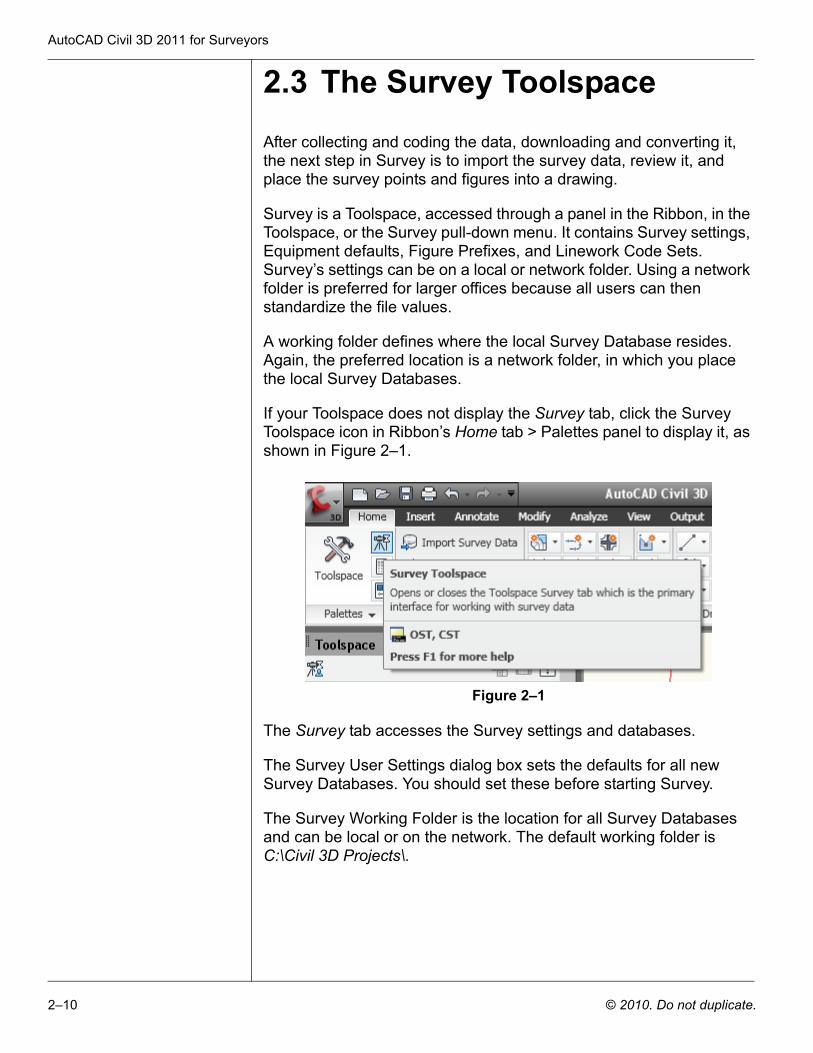
If your Toolspace does not display the Survey tab, click the Survey Toolspace icon in Ribbon’s Home tab > Palettes panel to display it, as shown in Figure 2–1.
Figure 2–1
The Survey tab accesses the Survey settings and databases.
The Survey User Settings dialog box sets the defaults for all new Survey Databases. You should set these before starting Survey.
The Survey Working Folder is the location for all Survey Databases and can be local or on the network. The default working folder is C:\Civil 3D Projects\.
Survey Level 1
© 2010. Do not duplicate. 2–11
Survey Database
A Survey Database is a subfolder in the working folder. The Survey Working Folder contains the Survey’s settings and observation database. This database contains the Survey’s Networks, Figures, and Survey Points.
Each local Survey Database references files to perform some of its tasks. The Equipment Database is an *.edb file and the Figure Prefix Database is an *. fdb file. The Equipment settings file contains values to estimate errors for the Least Squares adjustment process. The Figure Prefix Database lists definitions for Survey figures (figure style and layers).The default location for these files is C:\Documents and Settings\All Users\Application Data\Autodesk\C3D 2011\enu\Survey.
Survey has four nodes: Import Events, Networks, Figures, and Survey Points. Import Events is where files are imported into the Survey’s networks. The files can be a coordinate, a field book, a LandXML file, and points from a drawing. When importing a file, depending on its contents, the import results in figures and points. Information in the file also populates portions of a Survey’s Network.
When importing a coordinate or field book file containing only coordinates, the Figures and Survey Points nodes are your focus.
When processing a file with observations, turned angles, zenith angles, slope distances, and setups, your focus is the network and its nodes.
Note: Survey Database folders cannot be deleted within AutoCAD Civil 3D Survey. If you want to delete the working folder, for example, this process must be manually done external to AutoCAD Civil 3D.
AutoCAD Civil 3D 2011 for Surveyors
2–12 © 2010. Do not duplicate.
Practice 2a Creating a Survey Database
In this practice you will set up a Survey project.
1. Open the file SUV1-Sec1-Survey.dwg from the following folder:
C:\Civil 3D Projects\Civil3D-training\Drawings
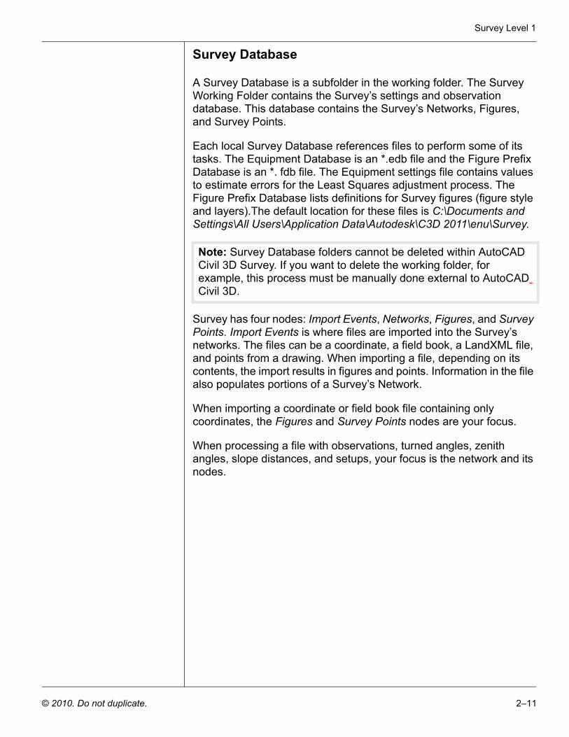
2. You might have to change the draw order to be able to view the other objects. In Model Space, select the image, right-click, and select Display Order > Send to Back, as shown in Figure 2–2.
Figure 2–2
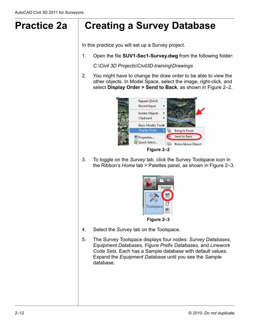
3. To toggle on the Survey tab, click the Survey Toolspace icon in the Ribbon’s Home tab > Palettes panel, as shown in Figure 2–3.
Figure 2–3
4. Select the Survey tab on the Toolspace.
5. The Survey Toolspace displays four nodes: Survey Databases, Equipment Databases, Figure Prefix Databases, and Linework Code Sets. Each has a Sample database with default values. Expand the Equipment Database until you see the Sample database.
Survey Level 1
© 2010. Do not duplicate. 2–13
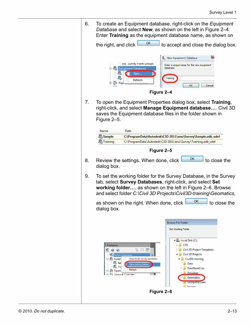
6. To create an Equipment database, right-click on the Equipment Database and select New, as shown on the left in Figure 2–4. Enter Training as the equipment database name, as shown on
the right, and click to accept and close the dialog box.
Figure 2–4
7. To open the Equipment Properties dialog box, select Training, right-click, and select Manage Equipment database…. Civil 3D saves the Equipment database files in the folder shown in Figure 2–5.
Figure 2–5
8. Review the settings. When done, click to close the dialog box.
9. To set the working folder for the Survey Database, in the Survey tab, select Survey Databases, right-click, and select Set working folder…, as shown on the left in Figure 2–6. Browse and select folder C:\Civil 3D Projects\Civil3D-training\Geomatics,
as shown on the right. When done, click to close the dialog box.
Figure 2–6
AutoCAD Civil 3D 2011 for Surveyors
2–14 © 2010. Do not duplicate.
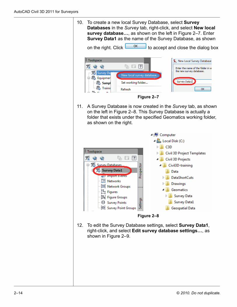
10. To create a new local Survey Database, select Survey Databases in the Survey tab, right-click, and select New local survey database…, as shown on the left in Figure 2–7. Enter Survey Data1 as the name of the Survey Database, as shown
on the right. Click to accept and close the dialog box
Figure 2–7
11. A Survey Database is now created in the Survey tab, as shown on the left in Figure 2–8. This Survey Database is actually a folder that exists under the specified Geomatics working folder, as shown on the right.
Figure 2–8
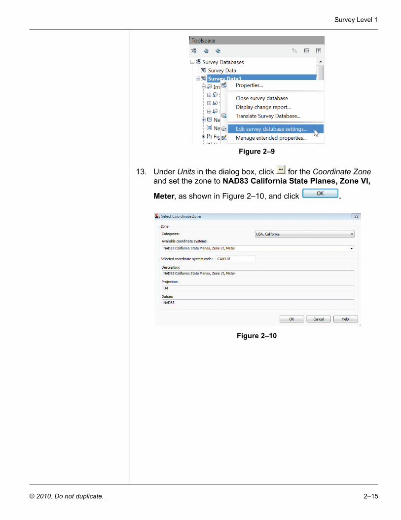
12. To edit the Survey Database settings, select Survey Data1, right-click, and select Edit survey database settings…, as shown in Figure 2–9.
Survey Level 1
© 2010. Do not duplicate. 2–15
Figure 2–9
13. Under Units in the dialog box, click for the Coordinate Zone and set the zone to NAD83 California State Planes, Zone VI,
Meter, as shown in Figure 2–10, and click .
Figure 2–10
AutoCAD Civil 3D 2011 for Surveyors
2–16 © 2010. Do not duplicate.
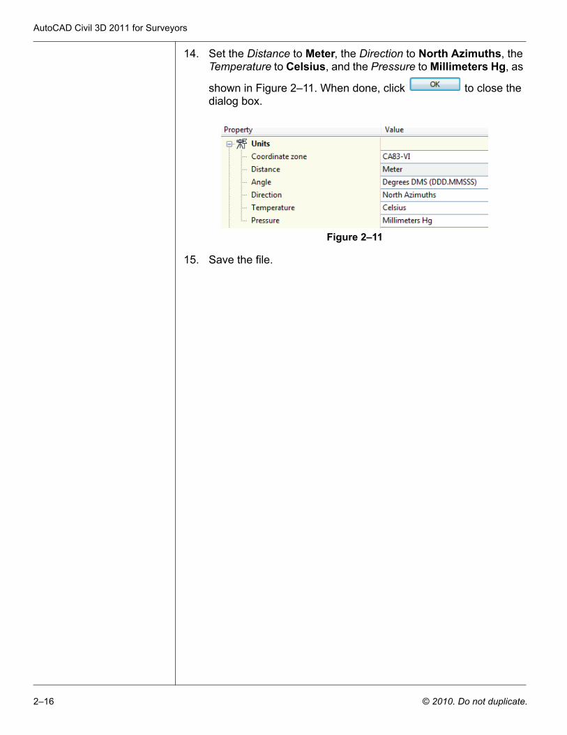
14. Set the Distance to Meter, the Direction to North Azimuths, the Temperature to Celsius, and the Pressure to Millimeters Hg, as
shown in Figure 2–11. When done, click to close the dialog box.
Figure 2–11
15. Save the file.
Survey Level 1
© 2010. Do not duplicate. 2–17
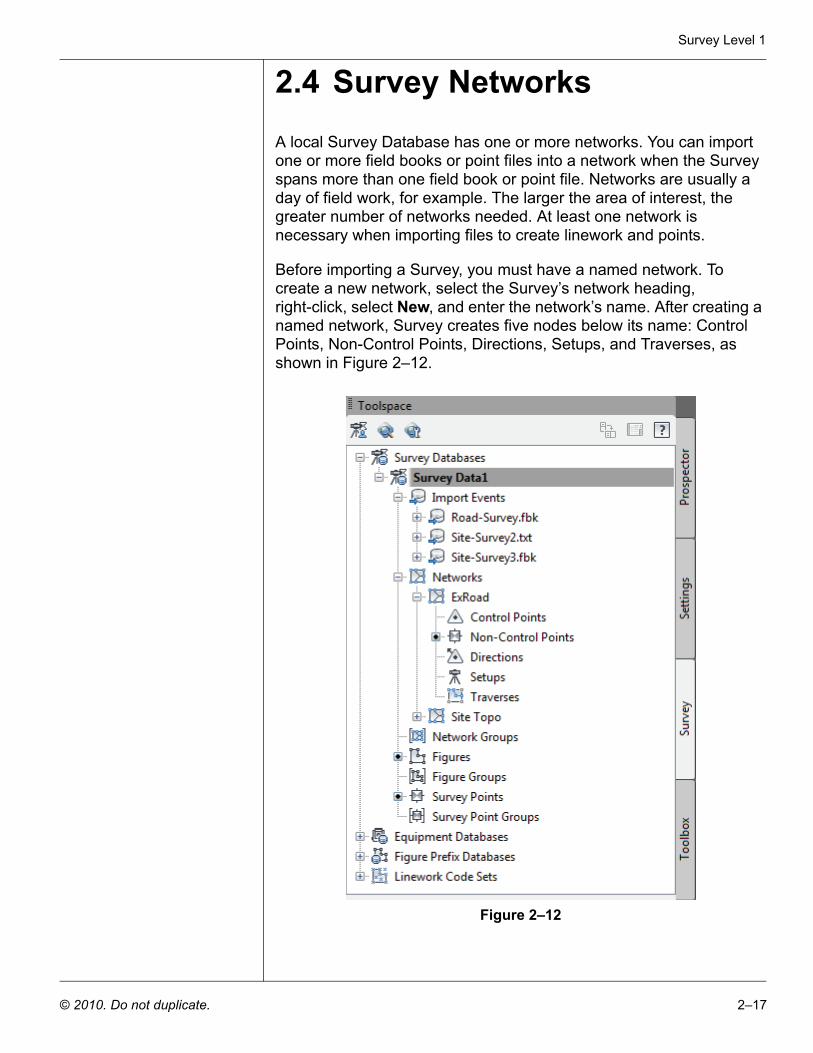
2.4 Survey NetworksA local Survey Database has one or more networks. You can import one or more field books or point files into a network when the Survey spans more than one field book or point file. Networks are usually a day of field work, for example. The larger the area of interest, the greater number of networks needed. At least one network is necessary when importing files to create linework and points.
Before importing a Survey, you must have a named network. To create a new network, select the Survey’s network heading, right-click, select New, and enter the network’s name. After creating a named network, Survey creates five nodes below its name: Control Points, Non-Control Points, Directions, Setups, and Traverses, as shown in Figure 2–12.
Figure 2–12
AutoCAD Civil 3D 2011 for Surveyors
2–18 © 2010. Do not duplicate.
You can import one or several field books or LandXML files into the same network. By default, each import supplements the previous import. When you re-import a file, Survey automatically deletes the information from the original file import and recalculates the observations from the re-imported file.
Importing multiple files with the correct settings creates a single network whose data is the combination of the imported files. This allows you to create traverse(s), or perform a Least Squares analysis from data that spans more than one file.
When importing a file, Survey sequentially processes each line, creating setups and processing the setup’s observations. When processing the setup’s observations, Survey stores them in the observation database and calculates a point’s preliminary coordinates from the observation values.
When toggling on interactive graphics, Survey displays the setups, draws figure linework, and populates the Control Points, Non-Control Points, Directions, and Setups.
When completing the import, Survey populates all or some of the nodes under the Networks heading.
Control points are NE or NEZ entries in a field book. Directions are azimuth entries between points used in the stationing process. Survey points are initially calculated coordinates from the file’s setups and observations. Any NE SS entries become non-control points. These points have coordinates, but are not control points (not used in a setup or as stationing points). You can promote them to control points by using them as part of a traverse or referencing them as part of a setup.
Non-control points can also be the result of importing a point coordinate file instead of an observation-based file.
Survey Level 1
© 2010. Do not duplicate. 2–19
Practice 2b Creating a Survey Network
In this practice you will create a Survey network. This practice assumes that you have successfully created a Survey Database.
Task 1 - Open drawing and database.
1. Continue working with the drawing from the previous practice or open the file SUV1-Sec1-Survey-.dwg from the following folder:
C:\Civil 3D Projects\Civil3D-training\Drawings
2. Select the Survey tab.
3. If you have not created the survey database, refer to Practice 3a Creating a Survey Database
4. Select Survey Data1. If this Survey project is not open (the label will not be bold), right-click and select Open for edit.
Task 2 - Create a network.
1. In the Survey tab, under Survey Data1, select the Networks heading, right-click, and select New.
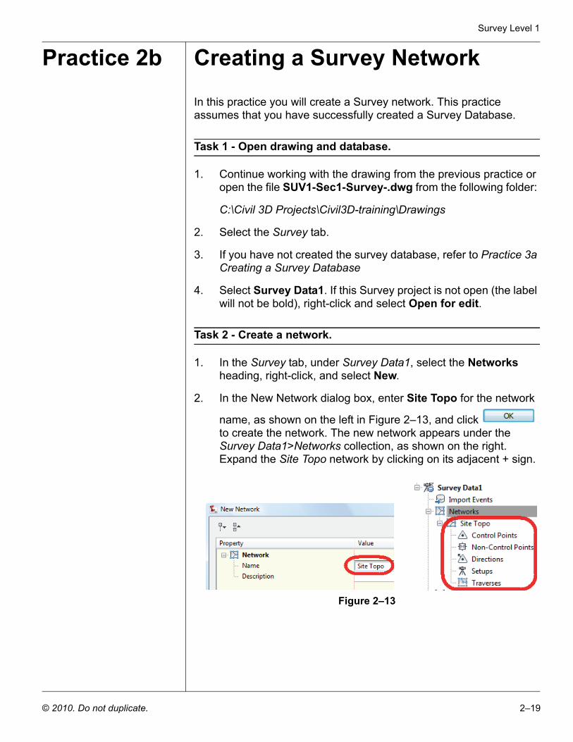
2. In the New Network dialog box, enter Site Topo for the network
name, as shown on the left in Figure 2–13, and click to create the network. The new network appears under the Survey Data1>Networks collection, as shown on the right. Expand the Site Topo network by clicking on its adjacent + sign.
Figure 2–13

AutoCAD Civil 3D 2011 for Surveyors
2–20 © 2010. Do not duplicate.
Review Questions
Question 1 If you need linework, do the point files have to be brought into AutoCAD Civil 3D through the Survey Database or can the linework be created by importing points through the Prospector?
Question 2 What are the major differences between using field books for creating linework and using text files with the P,N,E,Z,D format that use Linework Code Sets?
Question 3 If you need to analyze the field data using the analysis tools available in the Survey Database, does this require a field book or a text file?