autodesk inventor 2016 creating sketches · pltw gateway – autodesk inventor sketching – page 6...
TRANSCRIPT
© 2011 Project Lead The Way, Inc. PLTW Gateway – Autodesk Inventor Sketching – Page 1
Autodesk Inventor 2016 Creating Sketches 2D Sketch Practice 1
1. Launch Autodesk Inventor 2016
2. Create a new Part file ( .ipt)
3. Save File As
a. Click on the save icon. b. Save you file onto your flash drive. c. Name your file 2D Sketch P1_Initails
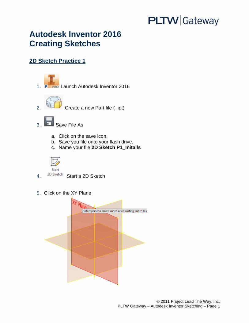
4. Start a 2D Sketch
5. Click on the XY Plane
© 2011 Project Lead The Way, Inc. PLTW Gateway – Autodesk Inventor Sketching – Page 2
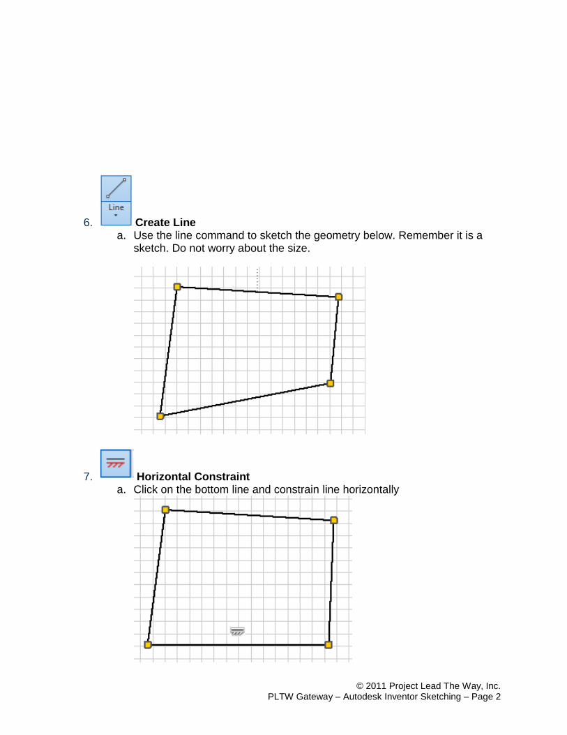
6. Create Line a. Use the line command to sketch the geometry below. Remember it is a
sketch. Do not worry about the size.
7. Horizontal Constraint a. Click on the bottom line and constrain line horizontally
© 2011 Project Lead The Way, Inc. PLTW Gateway – Autodesk Inventor Sketching – Page 3
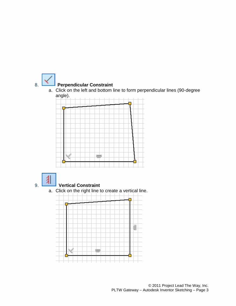
8. Perpendicular Constraint a. Click on the left and bottom line to form perpendicular lines (90-degree
angle).
9. Vertical Constraint a. Click on the right line to create a vertical line.
© 2011 Project Lead The Way, Inc. PLTW Gateway – Autodesk Inventor Sketching – Page 4
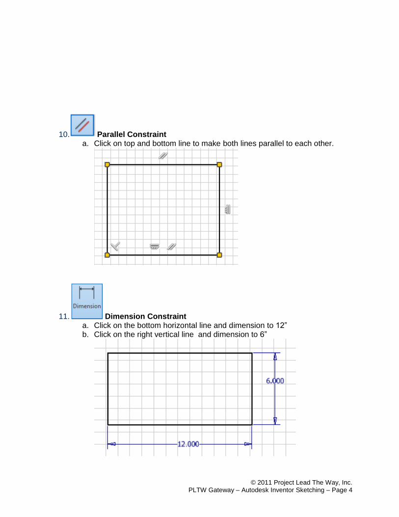
10. Parallel Constraint a. Click on top and bottom line to make both lines parallel to each other.
11. Dimension Constraint a. Click on the bottom horizontal line and dimension to 12” b. Click on the right vertical line and dimension to 6”
© 2011 Project Lead The Way, Inc. PLTW Gateway – Autodesk Inventor Sketching – Page 5
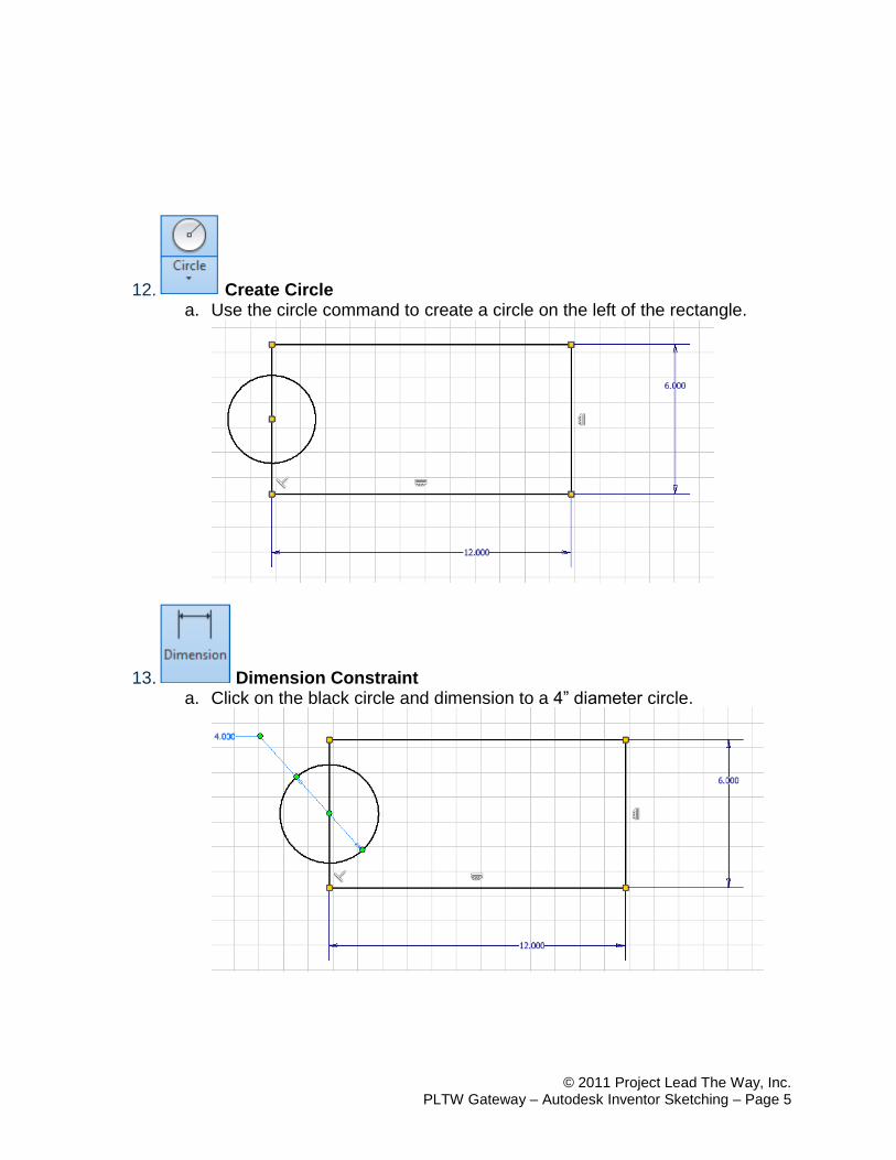
12. Create Circle a. Use the circle command to create a circle on the left of the rectangle.
13. Dimension Constraint a. Click on the black circle and dimension to a 4” diameter circle.
© 2011 Project Lead The Way, Inc. PLTW Gateway – Autodesk Inventor Sketching – Page 6
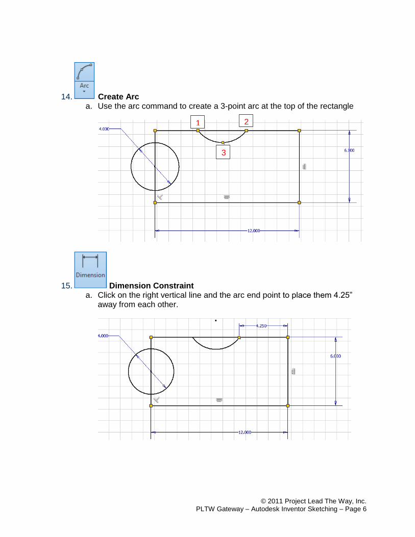
14. Create Arc a. Use the arc command to create a 3-point arc at the top of the rectangle
15. Dimension Constraint a. Click on the right vertical line and the arc end point to place them 4.25”
away from each other.
1 2
3
© 2011 Project Lead The Way, Inc. PLTW Gateway – Autodesk Inventor Sketching – Page 7
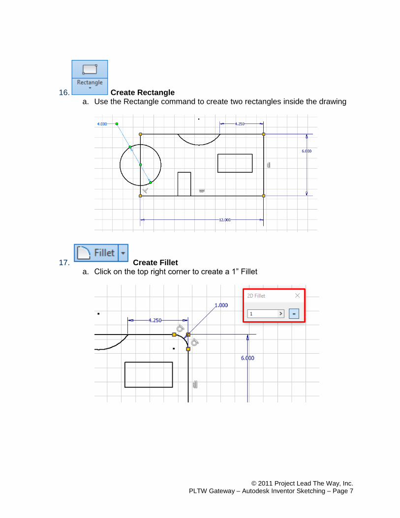
16. Create Rectangle a. Use the Rectangle command to create two rectangles inside the drawing
17. Create Fillet a. Click on the top right corner to create a 1” Fillet
© 2011 Project Lead The Way, Inc. PLTW Gateway – Autodesk Inventor Sketching – Page 8
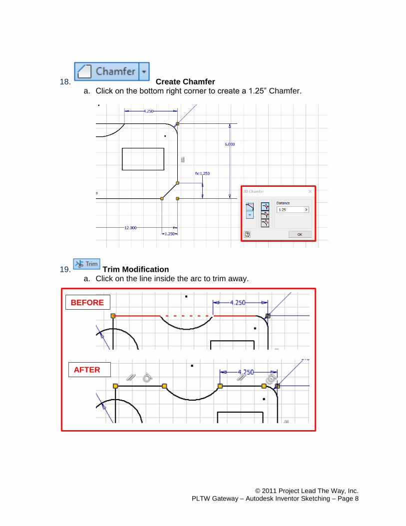
18. Create Chamfer a. Click on the bottom right corner to create a 1.25” Chamfer.
19. Trim Modification a. Click on the line inside the arc to trim away.
BEFORE
AFTER
© 2011 Project Lead The Way, Inc. PLTW Gateway – Autodesk Inventor Sketching – Page 9
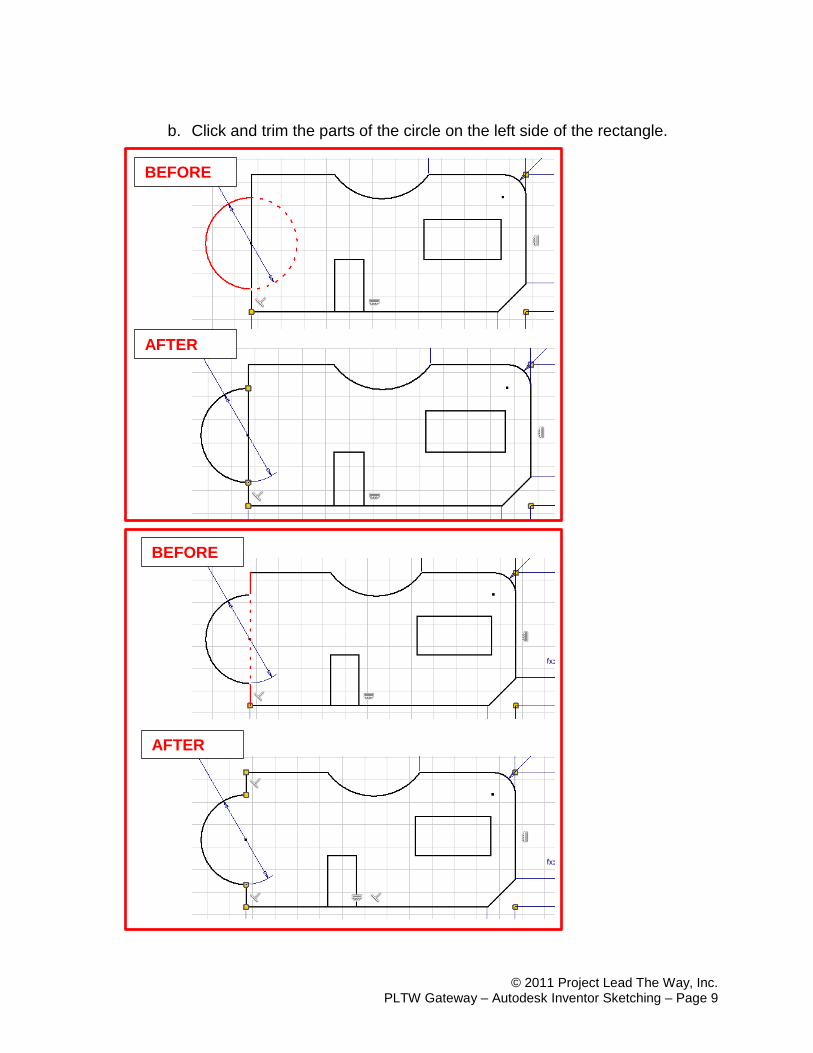
b. Click and trim the parts of the circle on the left side of the rectangle.
BEFORE
AFTER
BEFORE
AFTER
© 2011 Project Lead The Way, Inc. PLTW Gateway – Autodesk Inventor Sketching – Page 10
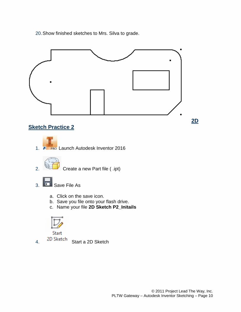
20. Show finished sketches to Mrs. Silva to grade.
2D Sketch Practice 2
1. Launch Autodesk Inventor 2016
2. Create a new Part file ( .ipt)
3. Save File As
a. Click on the save icon. b. Save you file onto your flash drive. c. Name your file 2D Sketch P2_Initails
4. Start a 2D Sketch
© 2011 Project Lead The Way, Inc. PLTW Gateway – Autodesk Inventor Sketching – Page 11
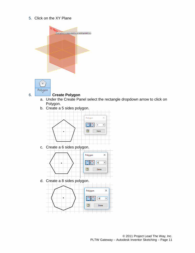
5. Click on the XY Plane
6. Create Polygon a. Under the Create Panel select the rectangle dropdown arrow to click on
Polygon. b. Create a 5 sides polygon.
c. Create a 6 sides polygon.
d. Create a 8 sides polygon.
© 2011 Project Lead The Way, Inc. PLTW Gateway – Autodesk Inventor Sketching – Page 12
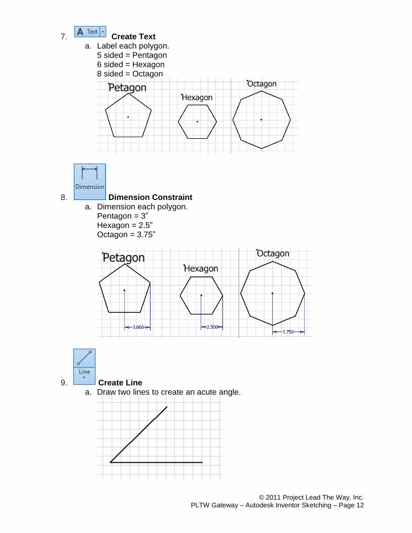
7. Create Text a. Label each polygon.
5 sided = Pentagon 6 sided = Hexagon 8 sided = Octagon
8. Dimension Constraint a. Dimension each polygon.
Pentagon = 3” Hexagon = 2.5” Octagon = 3.75”
9. Create Line a. Draw two lines to create an acute angle.
© 2011 Project Lead The Way, Inc. PLTW Gateway – Autodesk Inventor Sketching – Page 13
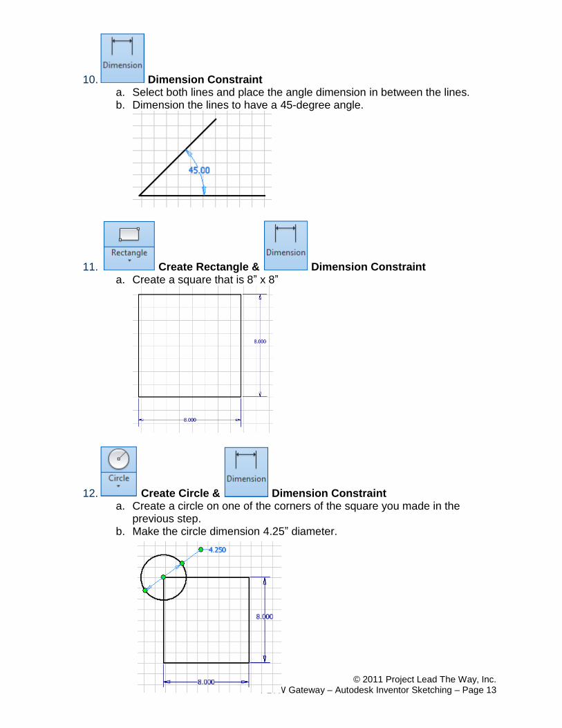
10. Dimension Constraint a. Select both lines and place the angle dimension in between the lines. b. Dimension the lines to have a 45-degree angle.
11. Create Rectangle & Dimension Constraint a. Create a square that is 8” x 8”
12. Create Circle & Dimension Constraint a. Create a circle on one of the corners of the square you made in the
previous step. b. Make the circle dimension 4.25” diameter.
© 2011 Project Lead The Way, Inc. PLTW Gateway – Autodesk Inventor Sketching – Page 14
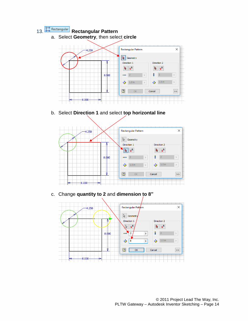
13. Rectangular Pattern a. Select Geometry, then select circle
b. Select Direction 1 and select top horizontal line
c. Change quantity to 2 and dimension to 8”
© 2011 Project Lead The Way, Inc. PLTW Gateway – Autodesk Inventor Sketching – Page 15
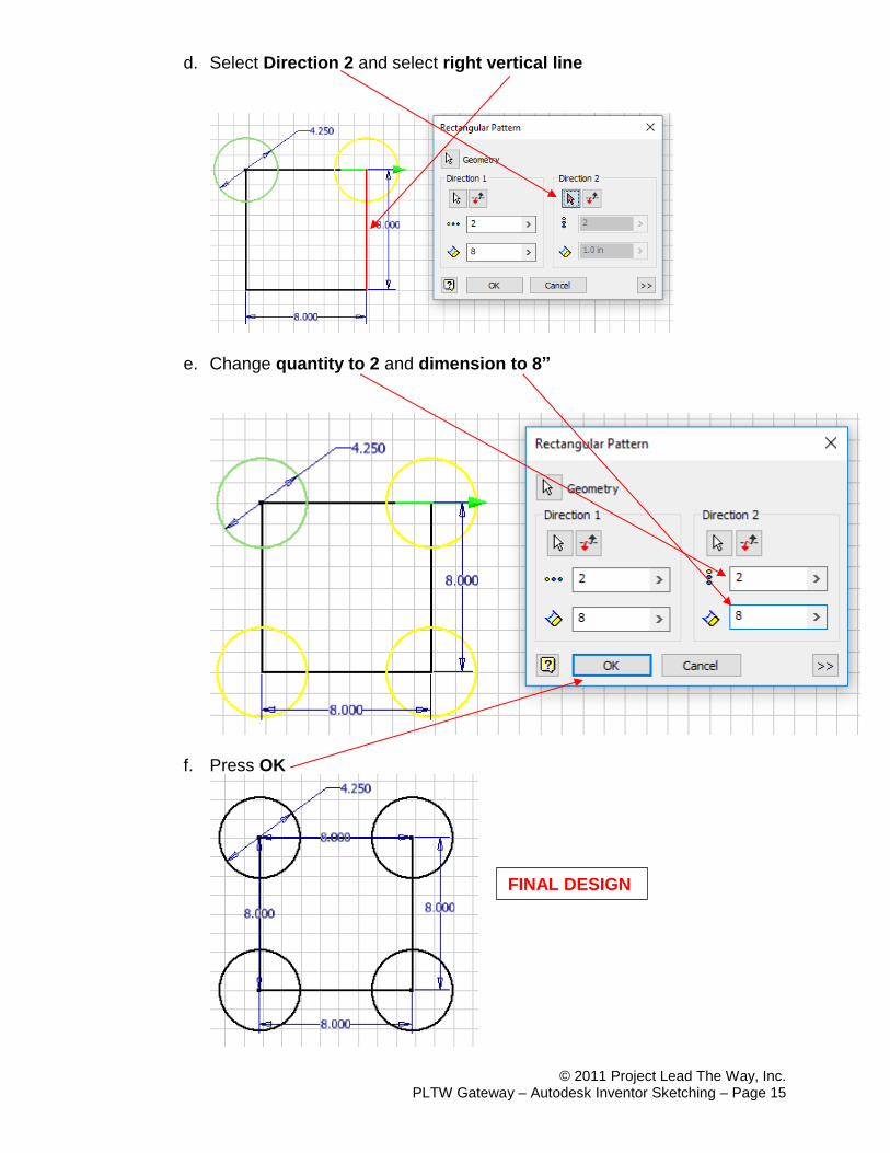
d. Select Direction 2 and select right vertical line
e. Change quantity to 2 and dimension to 8”
f. Press OK
FINAL DESIGN

© 2011 Project Lead The Way, Inc. PLTW Gateway – Autodesk Inventor Sketching – Page 16
14. Create Circle & Dimension Constraint a. Create a circle with a diameter of 6”
15. Create Circle & Dimension Constraint a. Create a 2” diameter circle on the circle made in the previous step.
© 2011 Project Lead The Way, Inc. PLTW Gateway – Autodesk Inventor Sketching – Page 17
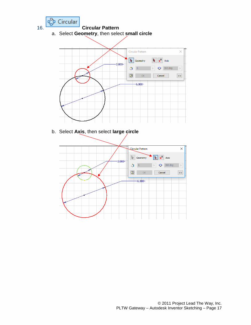
16. Circular Pattern a. Select Geometry, then select small circle
b. Select Axis, then select large circle
© 2011 Project Lead The Way, Inc. PLTW Gateway – Autodesk Inventor Sketching – Page 18
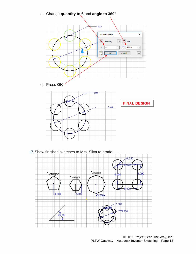
c. Change quantity to 6 and angle to 360”
d. Press OK
17. Show finished sketches to Mrs. Silva to grade.