autodesk inventor lt - digital...
TRANSCRIPT

Autodesk®
Inventor LT™
2010
Autodesk Official Training Guide
Essentials
529B1-050000-CM45AJuly 2009
Learning Autodesk® Inventor LT ™ 2010, Volume 1Hands-on exercises demonstrate the fundamental principles of 3D parametricpart design and the creation of production-ready part drawings.

© 2009 Autodesk, Inc. All rights reserved.
Except as otherwise permitted by Autodesk, Inc., this publication, or parts thereof, may not be reproduced inany form, by any method, for any purpose.
Certain materials included in this publication are reprinted with the permission of the copyright holder.
Trademarks
The following are registered trademarks or trademarks of Autodesk, Inc., and/or its subsidiaries and/or affiliates in the USAand other countries: 3DEC (design/logo), 3December, 3December.com, 3ds Max, ADI, Algor, Alias, Alias (swirl design/logo),AliasStudio, Alias|Wavefront (design/logo), ATC, AUGI, AutoCAD, AutoCAD Learning Assistance, AutoCAD LT, AutoCADSimulator, AutoCAD SQL Extension, AutoCAD SQL Interface, Autodesk, Autodesk Envision, Autodesk Intent, AutodeskInventor, Autodesk Map, Autodesk MapGuide, Autodesk Streamline, AutoLISP, AutoSnap, AutoSketch, AutoTrack,Backburner, Backdraft, Built with ObjectARX (logo), Burn, Buzzsaw, CAiCE, Can You Imagine, Character Studio, Cinestream,Civil 3D, Cleaner, Cleaner Central, ClearScale, Colour Warper, Combustion, Communication Specification, Constructware,Content Explorer, Create>what’s>Next> (design/logo), Dancing Baby (image), DesignCenter, Design Doctor, Designer’sToolkit, DesignKids, DesignProf, DesignServer, DesignStudio, Design|Studio (design/logo), Design Web Format, Discreet,DWF, DWG, DWG (logo), DWG Extreme, DWG TrueConvert, DWG TrueView, DXF, Ecotect, Exposure, Extending the DesignTeam, Face Robot, FBX, Fempro, Filmbox, Fire, Flame, Flint, FMDesktop, Freewheel, Frost, GDX Driver, Gmax, GreenBuilding Studio, Heads-up Design, Heidi, HumanIK, IDEA Server, i-drop, ImageModeler, iMOUT, Incinerator, Inferno,Inventor, Inventor LT, Kaydara, Kaydara (design/logo), Kynapse, Kynogon, LandXplorer, Lustre, MatchMover, Maya,Mechanical Desktop, Moldflow, Moonbox, MotionBuilder, Movimento, MPA, MPA (design/logo), Moldflow PlasticsAdvisers, MPI, Moldflow Plastics Insight, MPX, MPX (design/logo), Moldflow Plastics Xpert, Mudbox, Multi-Master Editing,NavisWorks, ObjectARX, ObjectDBX, Open Reality, Opticore, Opticore Opus, Pipeplus, PolarSnap, PortfolioWall, Poweredwith Autodesk Technology, Productstream, ProjectPoint, ProMaterials, RasterDWG, Reactor, RealDWG, Real-time Roto,REALVIZ, Recognize, Render Queue, Retimer, Reveal, Revit, Showcase, ShowMotion, SketchBook, Smoke, Softimage,Softimage|XSI (design/logo), Sparks, SteeringWheels, Stitcher, Stone, StudioTools, Topobase, Toxik, TrustedDWG,ViewCube, Visual, Visual Construction, Visual Drainage, Visual Landscape, Visual Survey, Visual Toolbox, Visual LISP, VoiceReality, Volo, Vtour, Wire, Wiretap, WiretapCentral, XSI, and XSI (design/logo).
All other brand names, product names, or trademarks belong to their respective holders.
Disclaimer
THIS PUBLICATION AND THE INFORMATION CONTAINED HEREIN IS MADE AVAILABLE BY AUTODESK, INC. “AS IS.”AUTODESK, INC. DISCLAIMS ALL WARRANTIES, EITHER EXPRESS OR IMPLIED, INCLUDING BUT NOT LIMITED TO ANY IMPLIEDWARRANTIES OF MERCHANTABILITY OR FITNESS FOR A PARTICULAR PURPOSE REGARDING THESE MATERIALS.
Published by: Autodesk, Inc. 111 Mclnnis Parkway San Rafael, CA 94903, USA
Contents ■ iii
Contents
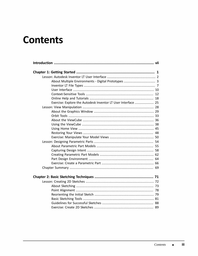
Introduction ...................................................................................................... vii
Chapter 1: Getting Started ................................................................................ 1Lesson: Autodesk Inventor LT User Interface ...................................................... 2
About Multiple Environments - Digital Prototypes ................................... 3Inventor LT File Types ............................................................................... 7User Interface .......................................................................................... 10Context-Sensitive Tools ........................................................................... 12Online Help and Tutorials ....................................................................... 18Exercise: Explore the Autodesk Inventor LT User Interface ..................... 25
Lesson: View Manipulation ............................................................................... 28About the Graphics Window ................................................................... 29Orbit Tools ............................................................................................... 33About the ViewCube ............................................................................... 36Using the ViewCube ................................................................................ 38Using Home View .................................................................................... 45Restoring Your Views .............................................................................. 48Exercise: Manipulate Your Model Views ................................................. 50
Lesson: Designing Parametric Parts .................................................................. 54About Parametric Part Models ............................................................... 55Capturing Design Intent .......................................................................... 58Creating Parametric Part Models ............................................................ 62Part Design Environment ........................................................................ 64Exercise: Create a Parametric Part .......................................................... 66
Chapter Summary ............................................................................................. 69
Chapter 2: Basic Sketching Techniques ............................................................ 71Lesson: Creating 2D Sketches ............................................................................ 72
About Sketching ...................................................................................... 73Point Alignment ...................................................................................... 78Reorienting the Initial Sketch .................................................................. 79Basic Sketching Tools ............................................................................... 81Guidelines for Successful Sketches ......................................................... 88Exercise: Create 2D Sketches .................................................................. 89
iv ■ Contents
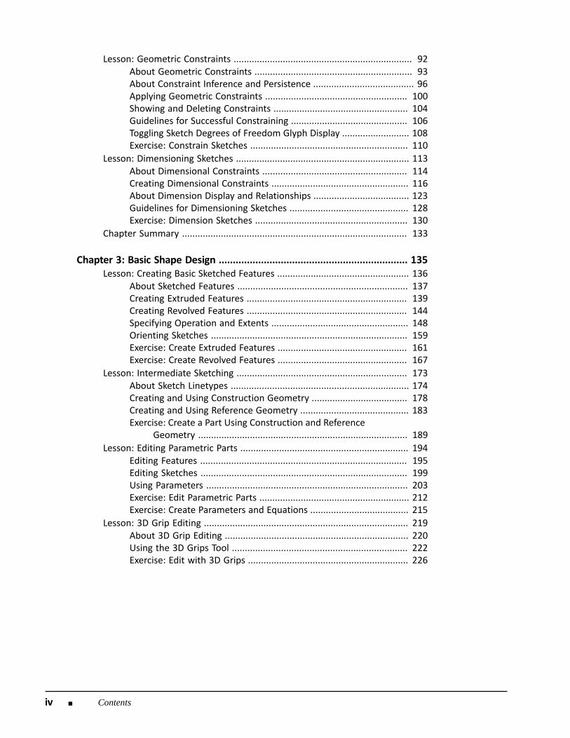
Lesson: Geometric Constraints ..................................................................... 92About Geometric Constraints ............................................................. 93About Constraint Inference and Persistence ....................................... 96Applying Geometric Constraints ....................................................... 100Showing and Deleting Constraints .................................................... 104Guidelines for Successful Constraining ............................................. 106Toggling Sketch Degrees of Freedom Glyph Display .......................... 108Exercise: Constrain Sketches ............................................................. 110
Lesson: Dimensioning Sketches ................................................................... 113About Dimensional Constraints ........................................................ 114Creating Dimensional Constraints ..................................................... 116About Dimension Display and Relationships ..................................... 123Guidelines for Dimensioning Sketches .............................................. 128Exercise: Dimension Sketches ........................................................... 130
Chapter Summary ....................................................................................... 133
Chapter 3: Basic Shape Design ................................................................... 135Lesson: Creating Basic Sketched Features ................................................... 136
About Sketched Features .................................................................. 137Creating Extruded Features .............................................................. 139Creating Revolved Features .............................................................. 144Specifying Operation and Extents ..................................................... 148Orienting Sketches ............................................................................ 159Exercise: Create Extruded Features .................................................. 161Exercise: Create Revolved Features .................................................. 167
Lesson: Intermediate Sketching .................................................................. 173About Sketch Linetypes ..................................................................... 174Creating and Using Construction Geometry ..................................... 178Creating and Using Reference Geometry .......................................... 183Exercise: Create a Part Using Construction and Reference
Geometry ................................................................................. 189Lesson: Editing Parametric Parts ................................................................. 194
Editing Features ................................................................................ 195Editing Sketches ................................................................................ 199Using Parameters .............................................................................. 203Exercise: Edit Parametric Parts .......................................................... 212Exercise: Create Parameters and Equations ...................................... 215
Lesson: 3D Grip Editing ............................................................................... 219About 3D Grip Editing ....................................................................... 220Using the 3D Grips Tool .................................................................... 222Exercise: Edit with 3D Grips .............................................................. 226

Contents ■ v
Lesson: Creating Work Features .................................................................. 230About Work Features ........................................................................ 231Creating Work Planes ........................................................................ 235Creating Work Axes ........................................................................... 240Creating Work Points ........................................................................ 243Exercise: Create Work Planes ............................................................ 249Exercise: Create Work Axes ............................................................... 253Exercise: Create Work Points ............................................................ 258
Lesson: Creating Basic Swept Shapes .......................................................... 262About Swept Shapes ......................................................................... 263Creating Sweep Features .................................................................. 265Guidelines for Creating Swept Shapes .............................................. 270Exercise: Create Sweep Features ...................................................... 273
Chapter Summary ....................................................................................... 276
Chapter 4: Basic View Creation .................................................................. 277Lesson: Drawing Creation Environment ...................................................... 278
About Creating Drawings .................................................................. 279Creating Drawings ............................................................................. 281About the Drawing Creation Environment ........................................ 282Using the Drawing Environment ....................................................... 284Exercise: Use the Drawing Creation Environment ............................. 287
Lesson: Base and Projected Views .............................................................. 289Creating Base Views .......................................................................... 290Creating Projected Views .................................................................. 293Properties of Editing Base and Projected Views ............................... 296Exercise: Create and Edit Base and Projected Views ......................... 298
Lesson: Section Views ................................................................................. 301Creating Section Views ..................................................................... 302Editing Section Views ........................................................................ 307Exercise: Create and Edit Section Views ........................................... 311
Lesson: Detail Views .................................................................................... 316About Detail Views ........................................................................... 317Creating Detail Views ........................................................................ 318Moving and Editing Detail Views ...................................................... 321Exercise: Create and Edit Detail Views .............................................. 325Exercise: Create and Edit Detail View Edge Shapes and
Connections ............................................................................. 328Lesson: Crop Views ..................................................................................... 331
Supported View Types and Displays ................................................. 332Creating Quick Cropped Views .......................................................... 334Creating Cropped Views with Sketches ............................................. 337Exercise: Create and Edit Cropped Views .......................................... 339
vi ■ Contents
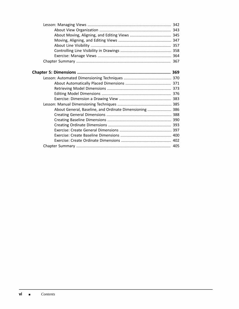
Lesson: Managing Views ............................................................................. 342About View Organization .................................................................. 343About Moving, Aligning, and Editing Views ...................................... 345Moving, Aligning, and Editing Views ................................................. 347About Line Visibility .......................................................................... 357Controlling Line Visibility in Drawings ............................................... 358Exercise: Manage Views .................................................................... 364
Chapter Summary ....................................................................................... 367
Chapter 5: Dimensions ............................................................................... 369Lesson: Automated Dimensioning Techniques ............................................ 370
About Automatically Placed Dimensions .......................................... 371Retrieving Model Dimensions ........................................................... 373Editing Model Dimensions ................................................................ 376Exercise: Dimension a Drawing View ................................................ 383
Lesson: Manual Dimensioning Techniques .................................................. 385About General, Baseline, and Ordinate Dimensioning ...................... 386Creating General Dimensions ............................................................ 388Creating Baseline Dimensions ........................................................... 390Creating Ordinate Dimensions .......................................................... 393Exercise: Create General Dimensions ................................................ 397Exercise: Create Baseline Dimensions ............................................... 400Exercise: Create Ordinate Dimensions .............................................. 402
Chapter Summary ....................................................................................... 405
Contents ■ iii
Contents
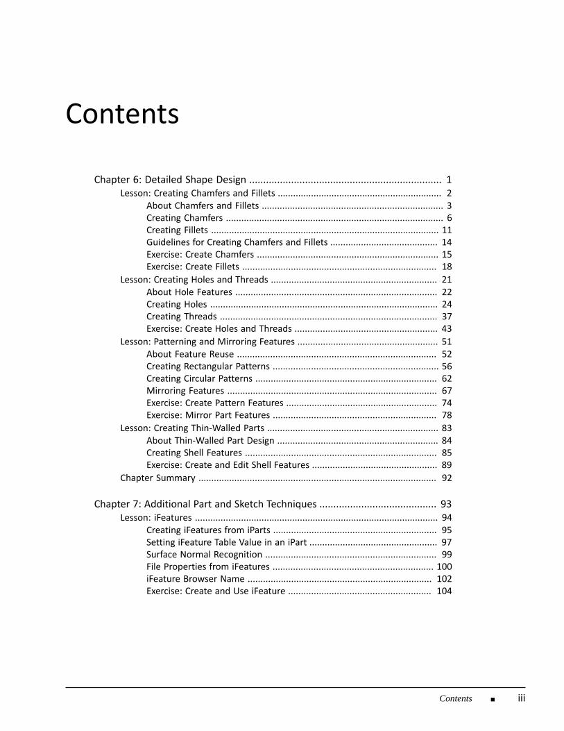
Chapter 6: Detailed Shape Design ..................................................................... 1Lesson: Creating Chamfers and Fillets ................................................................ 2
About Chamfers and Fillets ....................................................................... 3Creating Chamfers ..................................................................................... 6Creating Fillets ......................................................................................... 11Guidelines for Creating Chamfers and Fillets .......................................... 14Exercise: Create Chamfers ....................................................................... 15Exercise: Create Fillets ............................................................................ 18
Lesson: Creating Holes and Threads ................................................................. 21About Hole Features ............................................................................... 22Creating Holes ......................................................................................... 24Creating Threads ..................................................................................... 37Exercise: Create Holes and Threads ........................................................ 43
Lesson: Patterning and Mirroring Features ....................................................... 51About Feature Reuse .............................................................................. 52Creating Rectangular Patterns ................................................................. 56Creating Circular Patterns ....................................................................... 62Mirroring Features .................................................................................. 67Exercise: Create Pattern Features ........................................................... 74Exercise: Mirror Part Features ................................................................ 78
Lesson: Creating Thin-Walled Parts ................................................................... 83About Thin-Walled Part Design ............................................................... 84Creating Shell Features ........................................................................... 85Exercise: Create and Edit Shell Features ................................................. 89
Chapter Summary ............................................................................................. 92
Chapter 7: Additional Part and Sketch Techniques .......................................... 93Lesson: iFeatures ............................................................................................... 94
Creating iFeatures from iParts ................................................................ 95Setting iFeature Table Value in an iPart .................................................. 97Surface Normal Recognition ................................................................... 99File Properties from iFeatures ............................................................... 100iFeature Browser Name ........................................................................ 102Exercise: Create and Use iFeature ........................................................ 104
iv ■ Contents
Lesson: Various Part and Sketch Techniques ............................................... 109Default Units for Material Styles ....................................................... 110Define Parameters on the Fly ........................................................... 1112D Spline Enhancements .................................................................. 112Creating 3D Silhouetted Curve Sketches ........................................... 115Exercise: Part and Sketch Techniques ............................................... 118
Lesson: User Coordinate System ................................................................. 123What is a UCS? ................................................................................. 124Place a UCS in a Part Model ............................................................. 125Create a Base View using a UCS ....................................................... 128Exercise: Create User Coordinate System ......................................... 131
Chapter Summary ....................................................................................... 135
Chapter 8: Annotations and Tables ............................................................ 137Lesson: Annotating Holes and Threads ....................................................... 138
About Hole and Thread Notes .......................................................... 139Working with Hole and Thread Notes ............................................... 140Creating Linear Dimension Thread Notes ......................................... 143About Hole Tables ............................................................................. 146Working with Hole Tables ................................................................. 148Exercise: Create and Edit Hole Notes ................................................ 159Exercise: Create and Edit Hole Tables ............................................... 162
Lesson: Creating Centerlines, Symbols, and Leaders ................................... 165About Centerlines and Center Marks ................................................ 166Creating Centerlines and Center Marks ............................................ 168About Symbols .................................................................................. 176Documenting Views with Symbols .................................................... 177About Leaders and Text .................................................................... 186Adding Leaders and Text ................................................................... 188Editing Leaders and Text ................................................................... 192Exercise: Add Centerlines, Center Marks, and Symbols .................... 195
Lesson: Revision Tables and Tags ................................................................ 199About Revision Tables and Tags ........................................................ 200Process of Working with Revision Tables and Tags ........................... 201Revision Table Styles ......................................................................... 202Adding a Revision Table .................................................................... 207About Editing Revision Tables ........................................................... 209Adding and Editing Revision Tags ...................................................... 213Exercise: Configure, Add, and Edit Revision Tables and Tags ............. 215
Chapter Summary ....................................................................................... 222

Contents ■ v
Chapter 9: Drawing Standards and Resources ........................................... 223Lesson: Setting Drawing Standards ............................................................. 224
About Styles ...................................................................................... 225Creating Styles with the Style Editor ................................................. 227About Drawing Standards ................................................................. 234Properties of Drawing Standards ...................................................... 235Defining the Active Standard ............................................................ 241Using Layers ...................................................................................... 244Exercise: Set Drawing Standards ....................................................... 251
Lesson: Drawing Resources ......................................................................... 255About Drawing Sheets ...................................................................... 256Creating Sheets ................................................................................. 258About Custom Borders and Title Blocks ............................................ 262Creating Custom Borders .................................................................. 264Creating Custom Title Blocks ............................................................ 268Exercise: Use Drawing Resources ...................................................... 271Exercise: Customize a Title Block ...................................................... 274
Chapter Summary ....................................................................................... 276
Chapter 10: Production Drawings .............................................................. 277Lesson: Supplemental Drawing View Techniques ........................................ 278
Section View Projection Methods ..................................................... 279View Block Insertion Point ................................................................ 280Inserting a Sheet View Into Model Space ......................................... 282Defining a New Base Point in Model Space ...................................... 284Inventor DWG File Version ................................................................ 286Exercise: Supplemental Drawing View Techniques ........................... 287
Lesson: Supplemental Drawing Annotation Techniques .............................. 293General Dimension Methods ............................................................ 294Arranging Dimensions ....................................................................... 298Additional Feature Control Frame Symbols ...................................... 301Exercise: Supplement Drawing Annotation Techniques .................... 303
Chapter Summary ....................................................................................... 306
Chapter 11: Data and Geometry Translation and Exchange ....................... 307Lesson: Import and Export .......................................................................... 308
File Types for Opening ...................................................................... 309Exporting as Another File Type ......................................................... 310Using Marked Up 2D DWF Files in Inventor ...................................... 313Task Scheduler Import and Export .................................................... 314DWF Publish Options ........................................................................ 316Exercise: Import and Export Data ..................................................... 318

vi ■ Contents
Lesson: AEC Exchange ................................................................................. 321About AEC Building Components ...................................................... 322Publishing AEC Building Components ............................................... 323Adding Connectors ............................................................................ 325Connector Edits ................................................................................. 327Exporting Building Components ........................................................ 328Exercise: Prepare and Publish AEC Content ...................................... 331
Chapter Summary ....................................................................................... 334
Appendix .................................................................................................... 335

vii
Introduction
Welcome to the Learning Autodesk Inventor LT 2010 training guide, training courseware for use inAuthorized Training Center (ATC®) locations, corporate training settings, and other classroom settings.
Although this courseware is designed for instructor-led courses, you can also use it for self-pacedlearning. The courseware encourages self-learning through the use of the Autodesk® Inventor LT™2010 Help system.
This introduction covers the following topics:
■ Course objectives■ Prerequisites■ Using this guide■ CD contents■ Completing the exercises■ Installing the exercise data files from the CD■ Work Path Setup■ Notes, tips, and warnings■ Feedback This guide is complementary to the software documentation. For detailed explanations of features andfunctionality, refer to the Help in the software.
Course Objectives
After completing this guide, you will be able to:
■ Identify the main user interface components, describe how to access different tools, view allaspects of your design by efficiently navigating around in 2D and 3D space, and describe thecharacteristics and benefits of a parametric part model.
■ Use sketch tools to create 2D sketch geometry, apply geometric constraints to control sketchgeometry, and add parametric dimensions to your sketch geometry.
■ Create features using the Extrude and Revolve tools, use reference and construction geometry,use the browser and shortcut menus to edit parametric parts, use the 3D Grips tool to edit partgeometry, create, locate, and utilize work features to perform modeling tasks, and create sweptshapes by sweeping a profile along a 2D or 3D path.
■ Navigate the Autodesk Inventor user interface when creating and editing drawing sheets, createbase and projected views of 3D parts, create and edit section views, detail views, and croppedviews, and manage drawing views.
■ Dimension drawings with automated and manual techniques.■ Create both chamfers and fillets on a part, use the Hole and Thread tools to place hole and thread
features on your part model, create rectangular and circular patterns and mirror existing features,and create thin-walled parts using the Shell tool.
viii ■ Introduction
■ Explain and utilize the enhancements associated with iFeatures, utilize the various part and sketchenhancements to create and modify sketch geometry, create model parameters, and set materialunits for a model material, explain the use of UCS in sketches and parts, and create and modify aUCS.
■ Create and edit hole and thread notes in drawings, add centerlines, center marks, and symbols toyour drawings, and configure, add, and edit revision tables and revision tags
■ Set drafting standards to control the appearance of drawing features, and use drawing resources tocreate multiple sheets and add borders and title blocks to your drawings.
■ Describe and utilize the enhancements associated with drawing views and view blocks and theenhancements associated with annotating drawings.
■ Import and export geometry using other file types and prepare and publish AEC buildingcomponents.
Prerequisites
This course is designed for new Autodesk Inventor LT users who want to learn the essential toolsand principles of 3D parametric part design and how to create production-ready part drawings usingAutodesk Inventor LT 2010.
It is recommended that you have:
■ A basic understanding of mechanical drafting or design.■ A working knowledge of Microsoft® Windows® XP or Microsoft® Windows® Vista.
Using This Guide
The lessons are independent of each other. However, it is recommended that you completethese lessons in the order that they are presented unless you are familiar with the concepts andfunctionality described in those lessons.
Each chapter contains:
■ Lessons Usually two or more lessons in each chapter.■ Exercises Practical, real-world examples for you to practice using the functionality you have just learned.
Each exercise contains step-by-step procedures and graphics to help you complete the exercisesuccessfully.
CD Contents
The CD attached to the back cover of this book contains all the data and drawings you need tocomplete the exercises in this guide.
Introduction ■ ix
Completing the Exercises
You can complete the exercise in two ways: using the book or on screen.
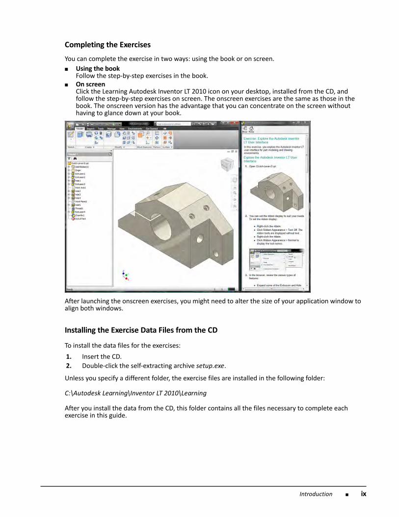
■ Using the book Follow the step-by-step exercises in the book.■ On screen Click the Learning Autodesk Inventor LT 2010 icon on your desktop, installed from the CD, and
follow the step-by-step exercises on screen. The onscreen exercises are the same as those in thebook. The onscreen version has the advantage that you can concentrate on the screen withouthaving to glance down at your book.
After launching the onscreen exercises, you might need to alter the size of your application window toalign both windows.
Installing the Exercise Data Files from the CD
To install the data files for the exercises:
1. Insert the CD. 2. Double-click the self-extracting archive setup.exe.
Unless you specify a different folder, the exercise files are installed in the following folder:
C:\Autodesk Learning\Inventor LT 2010\Learning
After you install the data from the CD, this folder contains all the files necessary to complete eachexercise in this guide.
x ■ Introduction
Work Path Setup
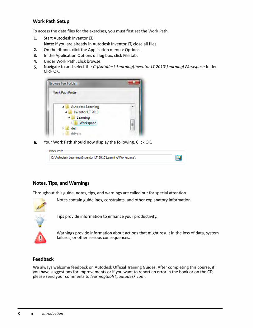
To access the data files for the exercises, you must first set the Work Path.
1. Start Autodesk Inventor LT. Note: If you are already in Autodesk Inventor LT, close all files.
2. On the ribbon, click the Application menu > Options. 3. In the Application Options dialog box, click File tab. 4. Under Work Path, click browse. 5.
Navigate to and select the C:\Autodesk Learning\Inventor LT 2010\Learning\Workspace folder.Click OK.
6.
Your Work Path should now display the following. Click OK.
Notes, Tips, and Warnings
Throughout this guide, notes, tips, and warnings are called out for special attention.
Notes contain guidelines, constraints, and other explanatory information.
Tips provide information to enhance your productivity.
Warnings provide information about actions that might result in the loss of data, systemfailures, or other serious consequences.
Feedback
We always welcome feedback on Autodesk Official Training Guides. After completing this course, ifyou have suggestions for improvements or if you want to report an error in the book or on the CD,please send your comments to [email protected].
Introduction ■ xi
Digital Prototyping
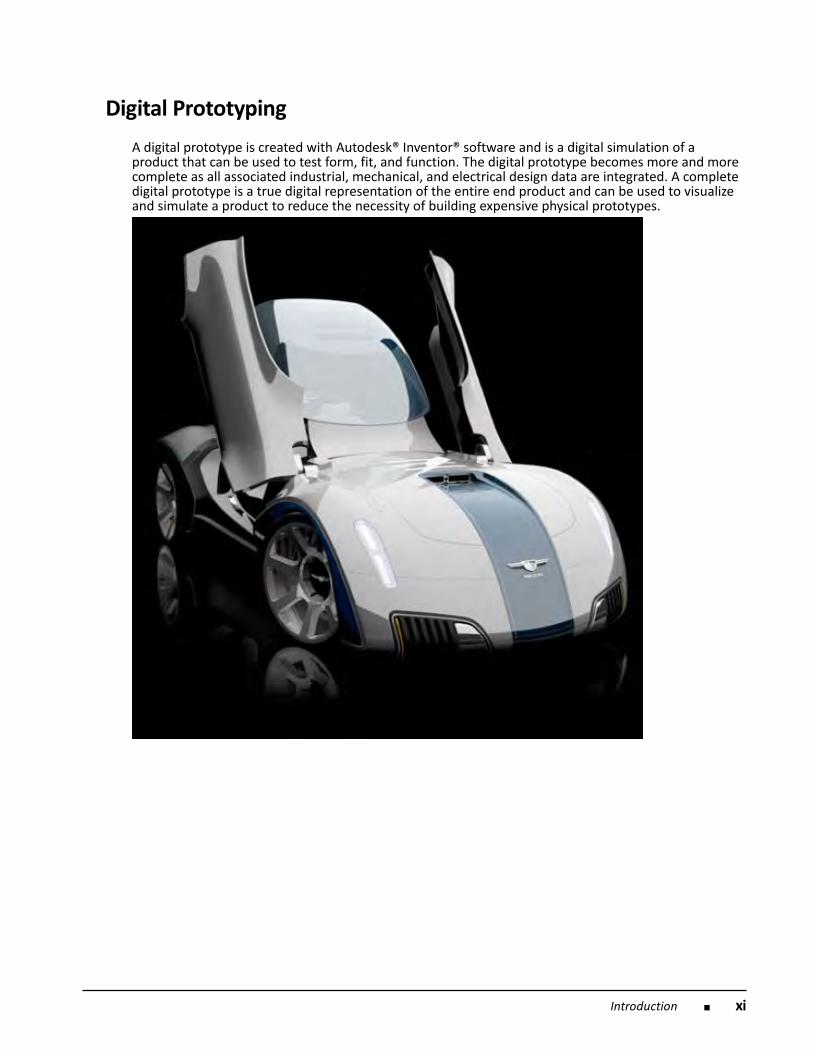
A digital prototype is created with Autodesk® Inventor® software and is a digital simulation of aproduct that can be used to test form, fit, and function. The digital prototype becomes more and morecomplete as all associated industrial, mechanical, and electrical design data are integrated. A completedigital prototype is a true digital representation of the entire end product and can be used to visualizeand simulate a product to reduce the necessity of building expensive physical prototypes.
xii ■ Introduction
What is Digital Prototyping?
Digital Prototyping gives conceptual design, engineering, and manufacturing departments theability to virtually explore a complete product before it becomes real. With Digital Prototyping,manufacturers can design, visualize, and simulate products from the conceptual design phase throughthe manufacturing process, boosting the level of communication with different stakeholders whilegetting more innovative products to market faster. By using a digital prototype created in Inventor,manufacturers can visualize and simulate the realworld performance of a design digitally, helpingreduce their reliance on costly physical prototypes.
What is the Autodesk Solution for Digital Prototyping?
Autodesk Inventor software takes manufacturers beyond 3D to Digital Prototyping. With Inventor,you can create a single digital model that gives you the ability to design, visualize, and simulate yourproducts:
■ Design: Integrate all design data into a single digital model, streamlining the design process and
increasing communication.■ Visualize: Create a virtual representation of the final product to review design intent, secure early
customer validation, and market products before they’re built.■ Simulate: Digitally simulate the real-world performance of your product, saving the time and
money required to build multiple physical prototypes. Inventor enables manufacturers to create a digital prototype, helping reduce reliance on costlyphysical prototypes and get more innovative products to market faster. The Autodesk® solution forDigital Prototyping brings together design data from all phases of the product development processinto a single digital model created in Inventor.
What Pain Points Does Digital Prototyping Address?
The manufacturing product development process today is dominated by islands of competency, eachpresenting its own technical challenges:
■ In the conceptual design phase, industrial designers and engineers often use paperbased methods
or digital formats that are incompatible with the digital information used in the engineeringphase. A lack of digital data, compatible formats, and automation keeps this island separate fromengineering—the conceptual design data must be recreated digitally downstream, resulting in losttime and money.
■ In the engineering phase, mechanical and electrical engineers use different systems and formats,and a lack of automation makes it difficult to capture and rapidly respond to change requests frommanufacturing. Another problem in the engineering phase: the geometric focus of typical 3D CADsoftware makes it difficult to create and use a digital prototype to validate and optimize productsbefore they are built, making it necessary to build multiple costly physical prototypes.
■ Manufacturing is at the downstream end of all the broken digital processes—the disconnectionbetween the conceptual design phase, the engineering components, electrical, and mechanical—and they receive this analog information in the form of drawings. The result is a heavy reliance onphysical prototypes and the subsequent impact on productivity and innovation.
■ Disconnected product development processes make it difficult to bring customer and marketingrequirements into the process early so customers can see exactly what the product will look likeand validate how it will function before it is delivered. The inability to involve the customer earlyin the product development process means that the customer can’t validate a design beforethe product goes to manufacturing. Customer requests for changes become exponentially moreexpensive to address the further along the product is in the manufacturing process. The result:companies have to build multiple physical prototypes for customer validation.

Introduction ■ xiii
Hasn't the Concept of Digital Prototyping Been Around for Years?
Although there has been talk about the benefits of Digital Prototyping for years, the budget for thetools required to build and test a true digital prototype has been out of reach for most manufacturingcompanies. Digital Prototyping solutions are usually expensive, customized installations for largeenterprises. Most out-of-the-box 3D modeling applications provide only part of the functionalityneeded to create a complete digital prototype.
What is Unique About the Autodesk Approach to Digital Prototyping? Scalable: The Autodesk solution for Digital Prototyping is scalable, flexible, and easy to integrate into
existing business processes. Using Inventor to create a single digital model, manufacturers can realizethe benefits of Digital Prototyping at their own pace, with minimal disruption to existing productiveworkflows. Attainable: The Autodesk solution for Digital Prototyping provides an easy to deploy and managesolution for mainstream manufacturers to create and maintain a single digital model that can be usedin all stages of production. Cost-effective: Delivering cost-effective software for design and manufacturing workgroups, anInventor-based Digital Prototyping solution delivers the fastest path to ROI. Autodesk has a provenrecord of making powerful desktop technology available to mainstream manufacturers.
How Do the Autodesk Manufacturing Products and Technology Drive Digital----Prototyping?
Inventor takes you beyond 3D to Digital Prototyping. The Autodesk solution for Digital Prototypingenables manufacturing workgroups to develop a single digital model, created in Inventor, that can beused in every stage of production—bridging the gaps that usually exist between conceptual design,engineering, and manufacturing teams. This single digital model simulates the complete product andgives engineers the ability to better design, visualize, and simulate their product with less reliance oncostly physical prototypes—thereby improving time to market, and increasing competitive advantage.Autodesk provides the interoperable tools required to create a complete digital prototype from theconceptual phase of a project through manufacturing.
xiv ■ Introduction
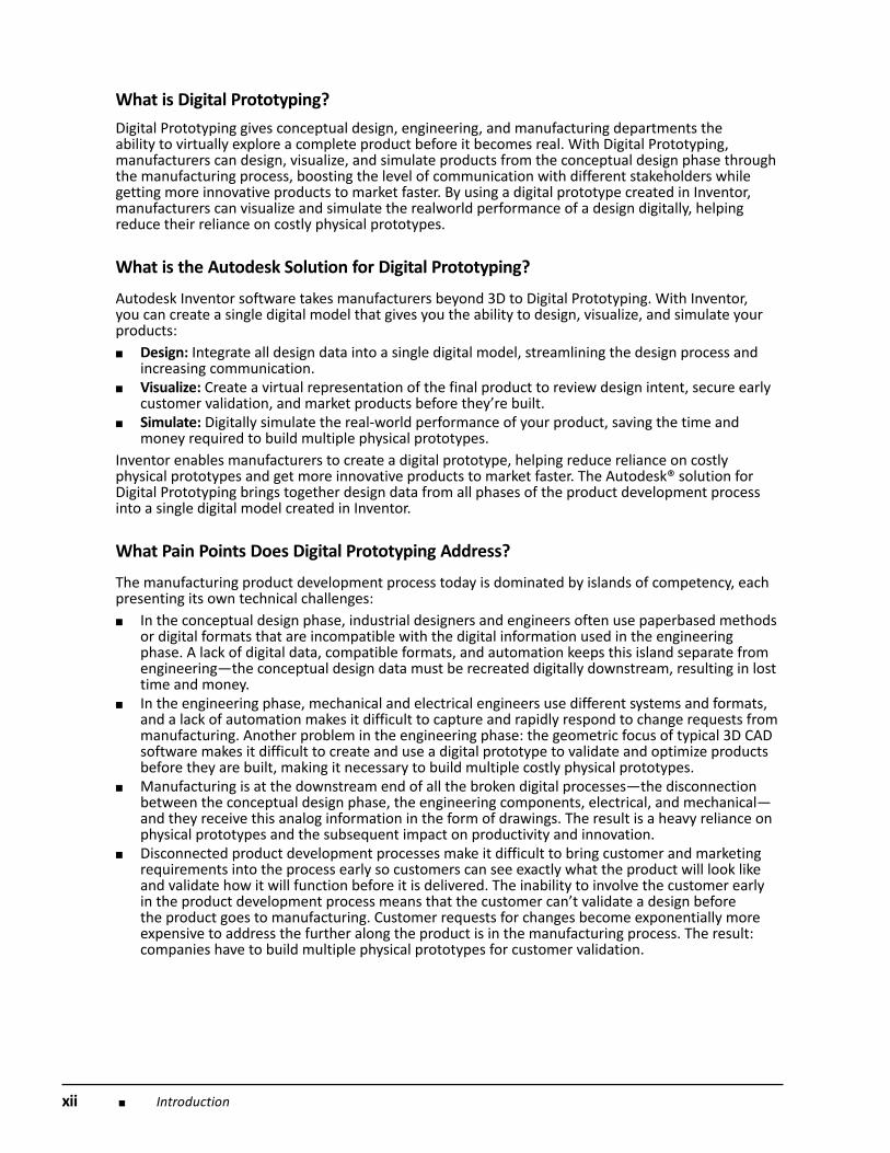
The Autodesk® Alias® product line enables you to work digitally from project outset using best-in-class industrial design tools. Capture ideas digitally—from initial sketches to 3D concept modelsusing products in the Alias product line—then share those designs with the engineering team usinga common file format, allowing a product’s industrial design data to be incorporated into the digitalprototype created in Inventor. Today, the look and feel of a machine or device is more important thanever for consumers, so industrial designers and engineers must share housing and user interfacesearly in the process.
With Autodesk® Showcase® software, you can quickly evaluate multiple design variations by creatingrealistic, accurate, and compelling imagery from 3D CAD data—helping reduce the time, cost, andneed for building physical prototypes. You can then interactively view the digital prototype in realisticenvironments, making it faster, easier, and less expensive to make design decisions. Autodesk Inventor software moves engineers beyond 3D and enables them to develop completedigital prototypes of their products. The Autodesk Inventor family of software provides the powerful—yet cost-effective and easy to learn—desktop technology engineers need to take advantage ofDigital Prototyping. Autodesk Inventor software enables engineers to integrate AutoCAD drawings and3D data into a single digital model, creating a virtual representation of the final product. Using thissingle digital model, you can design, visualize, and simulate products digitally. The model serves as adigital prototype that is refined and used to validate design functions, helping to reduce reliance onphysical prototypes and minimize manufacturing costs.■ Functional Design: Autodesk Inventor software products combine an intuitive 3D mechanical
design environment for creating parts and assemblies with functional design tools that enableengineers to focus on a design’s function, not geometry creation—letting the software drivethe automatic creation of intelligent components such as plastic parts, steel frames, rotatingmachinery, tube and pipe runs, and electrical cable and wire harnesses. Reducing the geometryburden helps engineers spend more time rapidly building and refining digital prototypes thatvalidate design functions and help optimize manufacturing costs.
Introduction ■ xv
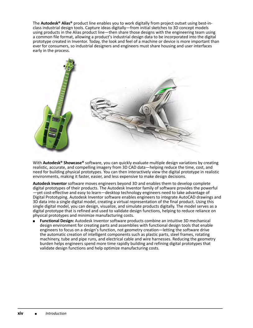
■ DWG™ Interoperability: Inventor provides direct read and write of native DWG files whilemaintaining full associativity to the 3D model without risking inaccurate translations. (DWG fromAutodesk is the original format for storing and sharing design data when working with AutoCADsoftware. With billions of DWG files circulating throughout every industry, it’s one of the mostcommonly used design data formats.) This gives engineers the freedom to safely reuse valuable2D DWG files to build accurate 3D part models, then communicate insights gained from DigitalPrototyping with partners and suppliers that rely on AutoCAD software.
■ Dynamic simulation: Autodesk Inventor delivers the best integrated simulation tools in theindustry. Tightly integrated tools for calculation, stress, deflection, and motion simulation makeit possible for engineers to optimize and validate a digital prototype before the product is built.Simulation is performed based on real-world constraints, so you know you can rely on thesimulation results. The dynamic simulation tools in Inventor enable engineers to evaluate multiplepotential solutions to a motion problem, making it possible to make the best design decisions andavoid costly mistakes.
■ Documentation: Autodesk Inventor software includes comprehensive tools to generateengineering and manufacturing documentation directly from a validated 3D digital prototype,helping design teams communicate more effectively. Inventor combines the benefits of associativedrawing views, so any changes made to the model are reflected in the drawing—with the powerand widespread acceptance of the DWG format to help reduce errors and deliver the design inless time.
■ Routed Systems: Inventor software’s automated tools for designing routed systems, includingcomplex tube and pipe runs, and electrical cable and harness design, allow you to createand validate a more complete digital prototype, which helps reduce errors and ECOs prior tomanufacturing and get to market faster.
■ Tooling: The tooling capabilities of Inventor software give designers and engineers intelligent toolsand mold base catalogs to quickly and accurately generate mold designs directly from a digitalprototype. Using the Inventor digital prototype, mold, tool, and die manufacturers can validatethe form, fit, and function of a mold design before it’s built, reducing errors and improving moldperformance.
To help validate and optimize designs before manufacturing, you can use the broad range of finiteelement analysis (FEA) and simulation tools in Algor simulation software, which will enhance theAutodesk solution for Digital Prototyping.

xvi ■ Introduction
AutoCAD Mechanical software is built to help mechanical designers and drafters simplify complexmechanical design work, enhancing productivity. Quickly detail production drawings using industry-specific manufacturing tools, reducing errors and saving hours of time. AutoCAD, one of the world’sleading design and professional drafting software, plays an important role in Digital Prototypingworkflows. AutoCAD gives you the power and flexibility to explore, document, and communicateideas. Both AutoCAD Mechanical and AutoCAD software enable engineers to accurately documentdigital prototypes created in Inventor, and communicate insights gained from Digital Prototyping withcolleagues, partners, and suppliers that rely on AutoCAD software. AutoCAD® Electrical software passes electrical design intent information for cables and conductorsdirectly to Autodesk Inventor software, adding valuable electrical controls design data to the digitalprototype created in Inventor. Inventor users can pass wire-connectivity information to AutoCADElectrical and automatically create the corresponding 2D schematics. The smooth integration betweenInventor and AutoCAD Electrical helps your electrical and mechanical teams work collaboratively andefficiently on 2D and 3D mechatronic product designs.

Introduction ■ xvii
To optimize plastic part and injection mold designs, use Autodesk® Moldflow® injection moldingsimulation software.
Autodesk® 3ds Max® software enables you to leverage engineering data to create advanced software-rendered and -animated visualizations of digital prototypes created in Inventor. 3ds Max contains acomplete suite of CAD data preparation, modeling, effects, and rendering tools to create the highestquality photorealistic and stylistic still and animated visualizations. Autodesk® Navisworks® software for manufacturing enables manufacturing companies to visualizecomplete manufacturing facilities, industrial machinery, factory floor models, and production lines ina single environment. The software supports complete assembly visualization and optimization, andenables you to combine CAD data from various design systems regardless of file format or size. Autodesk’s data management tools allow design workgroups to manage and track all the designcomponents for a digital prototype, helping you to better reuse design data, manage bills of material,and promote early collaboration with manufacturing teams and clients. With the Autodesk® Vaultfamily of data management applications, design, engineering, and manufacturing workgroups canmanage the Digital Prototyping process by helping reduce time organizing files, avoid costly mistakes,and more efficiently release and revise designs. You can further facilitate Digital Prototyping workflowswith Autodesk® Design Review software, the all-digital way to review, measure, mark up, and trackchanges to designs—all without the original creation software.

xviii ■ Introduction
What Can Customers Do with the Autodesk Solution for Digital Prototyping----Today?
Industrial designers use Autodesk Alias products to digitally sketch design ideas and create 3D digitalconcept models for validation that then can be shared with engineering or manufacturing teams.
Engineers use Autodesk Inventor to explore ideas with simple, functional representations that helpgenerate a digital prototype. Inventor software delivers the best bidirectional interoperability on themarket between 2D and 3D mechanical and electrical design applications. Integrated stress analysisand motion simulation help engineers optimize and validate complete designs digitally and confirmthat customer requirements are met even before a product is built.
Manufacturing teams benefit from accessing the most current and accurate data (release drawings,models, and BOMs)—avoiding mistakes caused by using outdated documents. They can provideexpertise earlier in the engineering process by sharing the digital prototype with Autodesk’s DWF™(Design Web Format™) technology to communicate, mark up, and measure designs—moving one stepcloser to true paperless manufacturing processes.
What Are the Business Benefits of Digital Prototyping?
According to an independent study by the Aberdeen Group, best-in-class manufacturers use DigitalPrototyping to build half the number of physical prototypes as the average manufacturer, get tomarket 58 days faster than average, experience 48 percent lower prototyping costs, and ultimatelydrive greater innovation in their products. The Autodesk solution for Digital Prototyping helpscustomers achieve results like these.

Introduction ■ xix
How Does the Autodesk Solution for Digital Prototyping Help Get Customers----to Best-in-Class?
By giving you the tools to develop a complete digital prototype, Autodesk helps you build fewerphysical prototypes—and ultimately get to market ahead of the competition with more innovativeproducts. Autodesk’s position is that moving to 3D is only the first step in creating a digital prototype.In today’s increasingly competitive global market, being best in class means using technology to stayahead of the competition—incorporating Digital Prototyping into the product development processgives you that edge. Autodesk provides this functionality through a complete, easy-to-learn set ofdesign applications and a wide range of partners for consultation regarding what is needed to makeDigital Prototyping a reality.

xx ■ Introduction
What is the Market Saying about Digital Prototyping?■ “To be best-in-class is not just about moving from 2D to 3D, but rather to push ahead to digital
prototyping to answer questions about your product before you start to build it.”—Start-IT
■ “IDC believes that with its new definition of digital prototyping, Autodesk is offering a productdevelopment solution to SMBs that will strengthen their competitiveness and give them thefunctional tools and processes required to achieve product excellence and profitability for years tocome."—Gisela Wilson and Michael Fauscette, IDC
■ “One of the primary reasons manufacturers aim to capture more product informationelectronically is to digitally prototype their product. As a result, they can reduce physicalprototyping and in turn, save time and development costs.”—Aberdeen Group
■ “It [Autodesk] provides a comprehensive range of software solutions for the manufacturingindustry including its flagship 3D design offering, Autodesk Inventor. The solutions redefineproduct design process by supporting and connecting all disciplines of product development, fromindustrial design to mechanical and electrical engineering, and manufacturing.”—Design News
■ “The ability to not only visualize product development in 3D but also to simulate how that productwould perform in the physical world are among the benefits assigned to digital prototyping.Research from consulting firm Aberdeen Group, in fact, shows that the use of digital prototypesfor top-performing companies both reduces their product development costs and speeds up howquickly products get to market.”—IndustryWeek
■ “The latest Autodesk manufacturing solutions redefine the product design process by supportingand natively connecting all of the disciplines involved in product development, from industrialdesign to mechanical and electrical engineering and manufacturing.”—The Manufacturer
■ “The Digital Prototyping approach is now embraced by some important manufacturers who oncepromoted enterprise PLM, including Boeing. Its new 787 Dreamliner, like the 777 before it, wasdigitally designed, but the digital definition from engineering was pushed into manufacturing vianew processes that replaced DCAC/MRM.”—Nancy Rouse-Tally, Desktop Engineering
■ “Autodesk is doing what it has always been good at—taking a technology idea and giving it thetop 80% of functionality at 20% of the price. Digital Prototyping is no different. It takes the idea of‘expensive’ out of PLM and brings it down to all those other users.”—Rachael Dalton-Taggart, PR, Marketing and the Business of CAD
■ “Before Inventor, it would typically take me 18 months to bring a new design to market,” JasonFaircloth, product manager and designer for Marin Bikes, Inc. says. “The finite-element andmotion analysis software have enabled me to almost eliminate physical prototypes. Withthe software, it’s now nine months, and getting faster—and the product is better. This is ourfuture.” The CAE capabilities of Inventor Professional enabled Faircloth to produce multiple“digital prototypes” so that the time-consuming process of physical prototyping was reduced oreliminated.—Desktop Engineering