autodesk revit 2014 bim management - sdc publications
TRANSCRIPT

Autodesk Revit 2014 BIM Management
® ®
Template and Family Creation
www.SDCpublications.comBetter Textbooks. Lower Prices.SDC
P U B L I C A T I O N S

Visit the following websites to learn more about this book:
Powered by TCPDF (www.tcpdf.org)
1–1
Chapter 1Creating Custom Templates
In this chapter you learn how to prepare project templates, create preset annotation styles, create title blocks, and create and apply view templates. You also review settings for structural, mechanical, and electrical projects.
This chapter contains the following topics:
Preparing Project Templates
Customizing Annotation Styles
Creating Title Blocks
View Templates
Settings for Mechanical and Electrical Projects
Settings for Structural Projects

1–2
Creating Custom Templates
© 2013, ASCENT - Center for Technical Knowledge® 1–3
1.1 Preparing Project Templates
A project template is an existing file that contains preloaded families, settings, views, sheets, schedules, and sometimes geometry, that can be used to create a new project. You can have several project templates for different types of projects or building types, such as residential, commercial, and industrial. If you do a lot of work for a specific client (e.g., a school system), you can also create a template specifically for their projects with associated title blocks and other information. The aim is to save time with standards so that you can concentrate on the design.
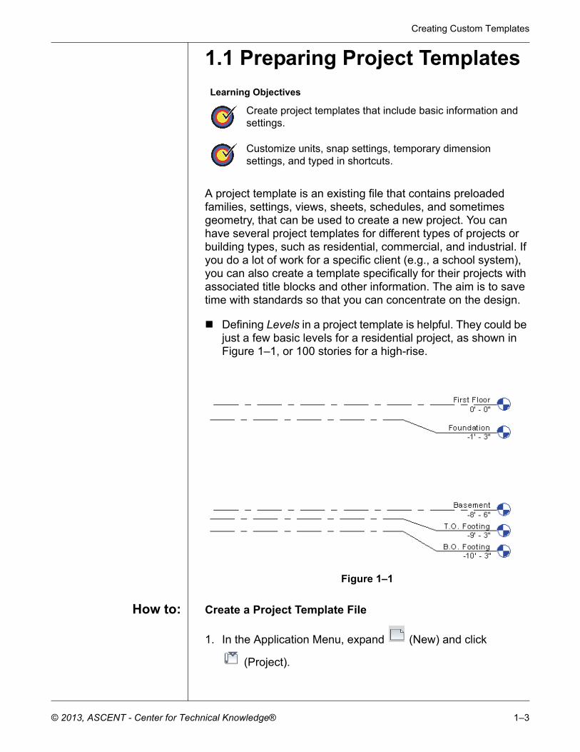
Defining Levels in a project template is helpful. They could bejust a few basic levels for a residential project, as shown inFigure 1–1, or 100 stories for a high-rise.
Figure 1–1
How to: Create a Project Template File
1. In the Application Menu, expand (New) and click
(Project).
Learning Objectives
Create project templates that include basic information and settings.
Customize units, snap settings, temporary dimension settings, and typed in shortcuts.
Autodesk Revit 2014 BIM Management: Template and Family Creation
1–4 © 2013, ASCENT - Center for Technical Knowledge®
2. In the New Project dialog box, select a template file to build from or select None to use a blank project file.
3. In the Create new area, select Project template, as shown in Figure 1–2.
Project template files have the extension .RTE.
Figure 1–2
4. Click .5. If you select <None> in the Template file list, you are
prompted to specify the initial unit system for the project: Imperial or Metric, as shown in Figure 1–3.
Figure 1–3
6. Add settings, families, views, etc., as needed to the new file.7. Save the project template file.
To save time, use an existing project or template that includes some of the basics you need rather than starting from scratch.
ManagingSettings
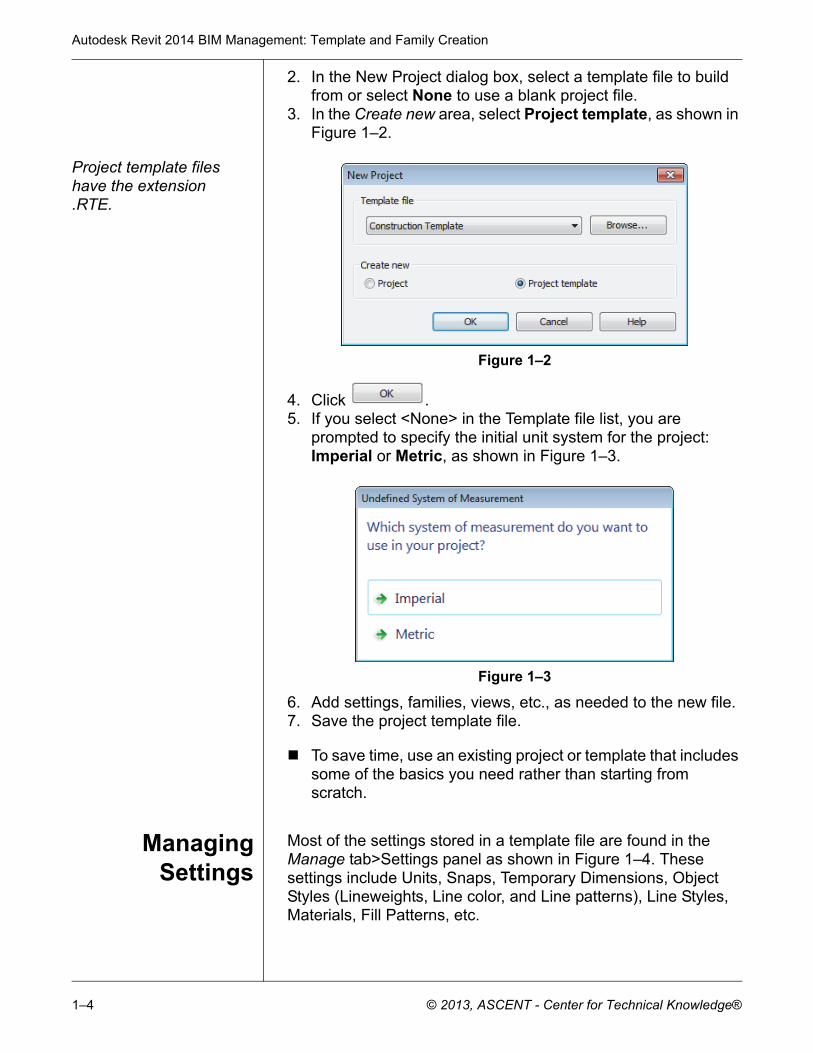
Most of the settings stored in a template file are found in the Manage tab>Settings panel as shown in Figure 1–4. These settings include Units, Snaps, Temporary Dimensions, Object Styles (Lineweights, Line color, and Line patterns), Line Styles, Materials, Fill Patterns, etc.
Creating Custom Templates
© 2013, ASCENT - Center for Technical Knowledge® 1–5
Figure 1–4
Specific Structural Settings, MEP Settings, and Panel Schedule Templates are also included in this grouping.
SystemFamilies
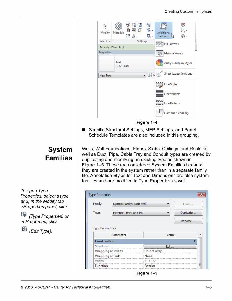
Walls, Wall Foundations, Floors, Slabs, Ceilings, and Roofs as well as Duct, Pipe, Cable Tray and Conduit types are created by duplicating and modifying an existing type as shown in Figure 1–5. These are considered System Families because they are created in the system rather than in a separate family file. Annotation Styles for Text and Dimensions are also system families and are modified in Type Properties as well.
To open Type Properties, select a type and, in the Modify tab >Properties panel, click
(Type Properties) or in Properties, click
(Edit Type).
Figure 1–5
Autodesk Revit 2014 BIM Management: Template and Family Creation
1–6 © 2013, ASCENT - Center for Technical Knowledge®
System Families can also be added when a project is in process, but it helps to have company standards created in the template.
Component Families, such as furniture, trees, beams, columns, mechanical equipment, and electrical devices can be loaded directly in a template file if there are types and sizes that are used frequently. Otherwise, they can be loaded from a library as the project progresses.
Views andSheets
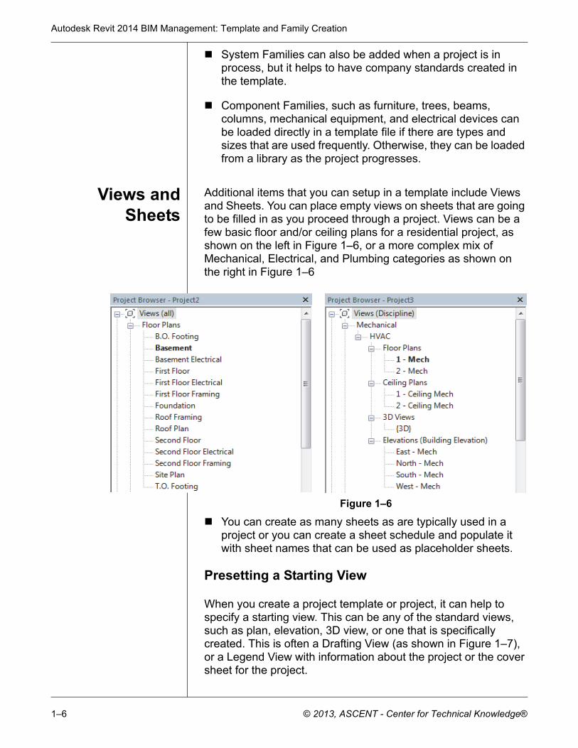
Additional items that you can setup in a template include Views and Sheets. You can place empty views on sheets that are going to be filled in as you proceed through a project. Views can be a few basic floor and/or ceiling plans for a residential project, as shown on the left in Figure 1–6, or a more complex mix of Mechanical, Electrical, and Plumbing categories as shown on the right in Figure 1–6
Figure 1–6
You can create as many sheets as are typically used in a project or you can create a sheet schedule and populate it with sheet names that can be used as placeholder sheets.
Presetting a Starting View
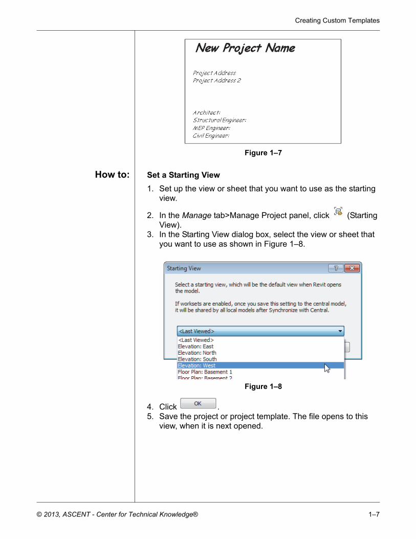
When you create a project template or project, it can help to specify a starting view. This can be any of the standard views, such as plan, elevation, 3D view, or one that is specifically created. This is often a Drafting View (as shown in Figure 1–7), or a Legend View with information about the project or the cover sheet for the project.
Creating Custom Templates
© 2013, ASCENT - Center for Technical Knowledge® 1–7
Figure 1–7
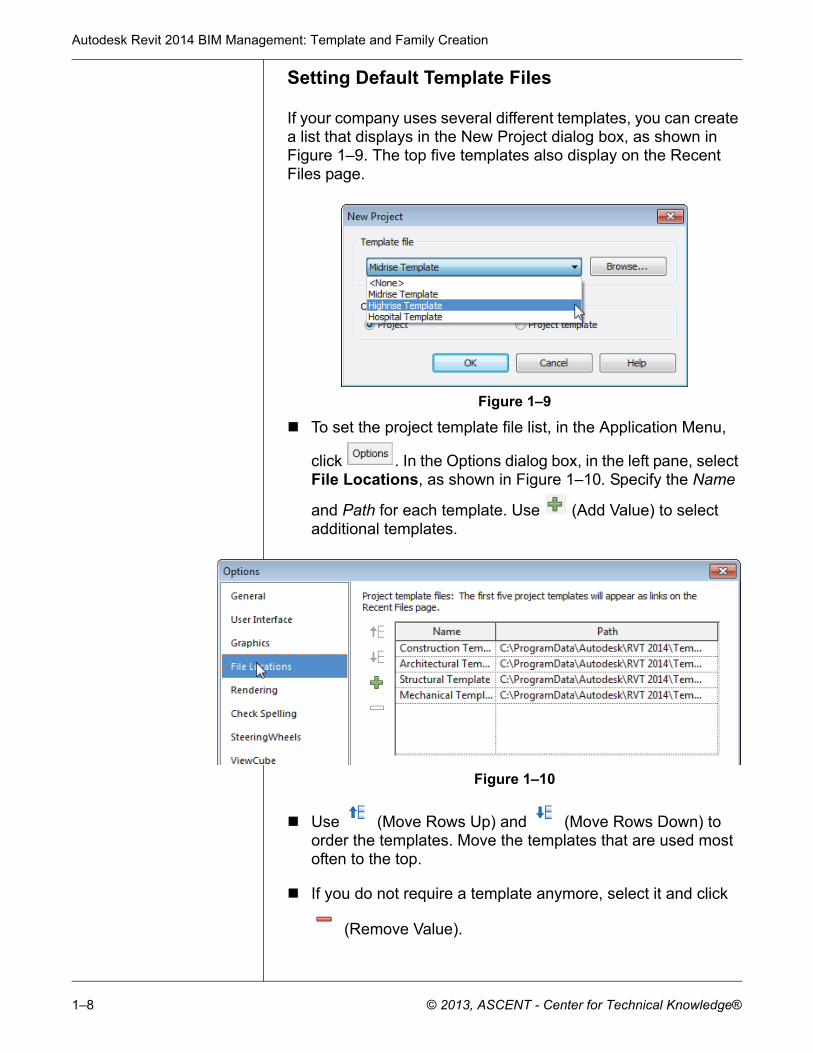
How to: Set a Starting View
1. Set up the view or sheet that you want to use as the starting view.
2. In the Manage tab>Manage Project panel, click (Starting View).
3. In the Starting View dialog box, select the view or sheet that you want to use as shown in Figure 1–8.
Figure 1–8
4. Click .5. Save the project or project template. The file opens to this
view, when it is next opened.
Autodesk Revit 2014 BIM Management: Template and Family Creation
1–8 © 2013, ASCENT - Center for Technical Knowledge®
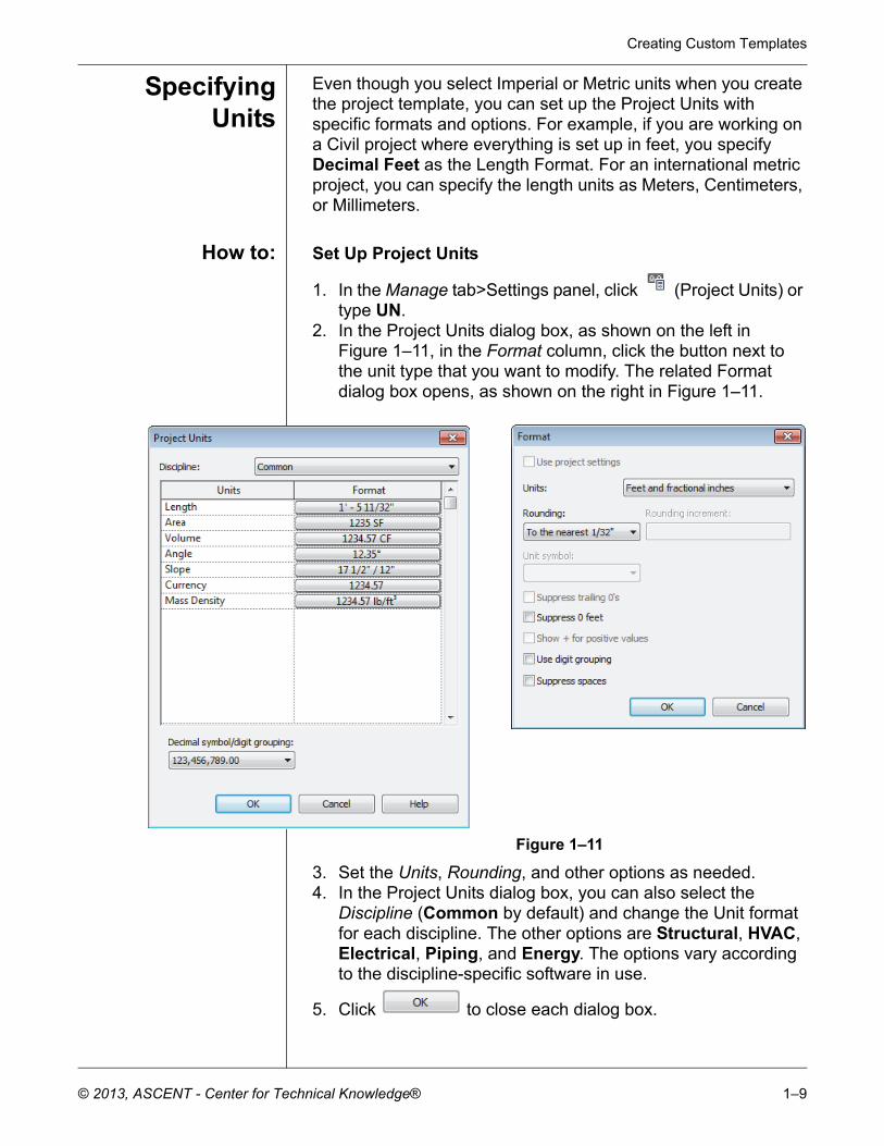
Setting Default Template Files
If your company uses several different templates, you can create a list that displays in the New Project dialog box, as shown in Figure 1–9. The top five templates also display on the Recent Files page.
Figure 1–9
To set the project template file list, in the Application Menu,
click . In the Options dialog box, in the left pane, select File Locations, as shown in Figure 1–10. Specify the Name
and Path for each template. Use (Add Value) to select additional templates.
Figure 1–10
Use (Move Rows Up) and (Move Rows Down) to order the templates. Move the templates that are used most often to the top.
If you do not require a template anymore, select it and click
(Remove Value).
Creating Custom Templates
© 2013, ASCENT - Center for Technical Knowledge® 1–9
SpecifyingUnits
Even though you select Imperial or Metric units when you create the project template, you can set up the Project Units with specific formats and options. For example, if you are working on a Civil project where everything is set up in feet, you specify Decimal Feet as the Length Format. For an international metric project, you can specify the length units as Meters, Centimeters, or Millimeters.
How to: Set Up Project Units
1. In the Manage tab>Settings panel, click (Project Units) or type UN.
2. In the Project Units dialog box, as shown on the left in Figure 1–11, in the Format column, click the button next to the unit type that you want to modify. The related Format dialog box opens, as shown on the right in Figure 1–11.
Figure 1–11
3. Set the Units, Rounding, and other options as needed.4. In the Project Units dialog box, you can also select the
Discipline (Common by default) and change the Unit format for each discipline. The other options are Structural, HVAC, Electrical, Piping, and Energy. The options vary according to the discipline-specific software in use.
5. Click to close each dialog box.
Autodesk Revit 2014 BIM Management: Template and Family Creation
1–10 © 2013, ASCENT - Center for Technical Knowledge®
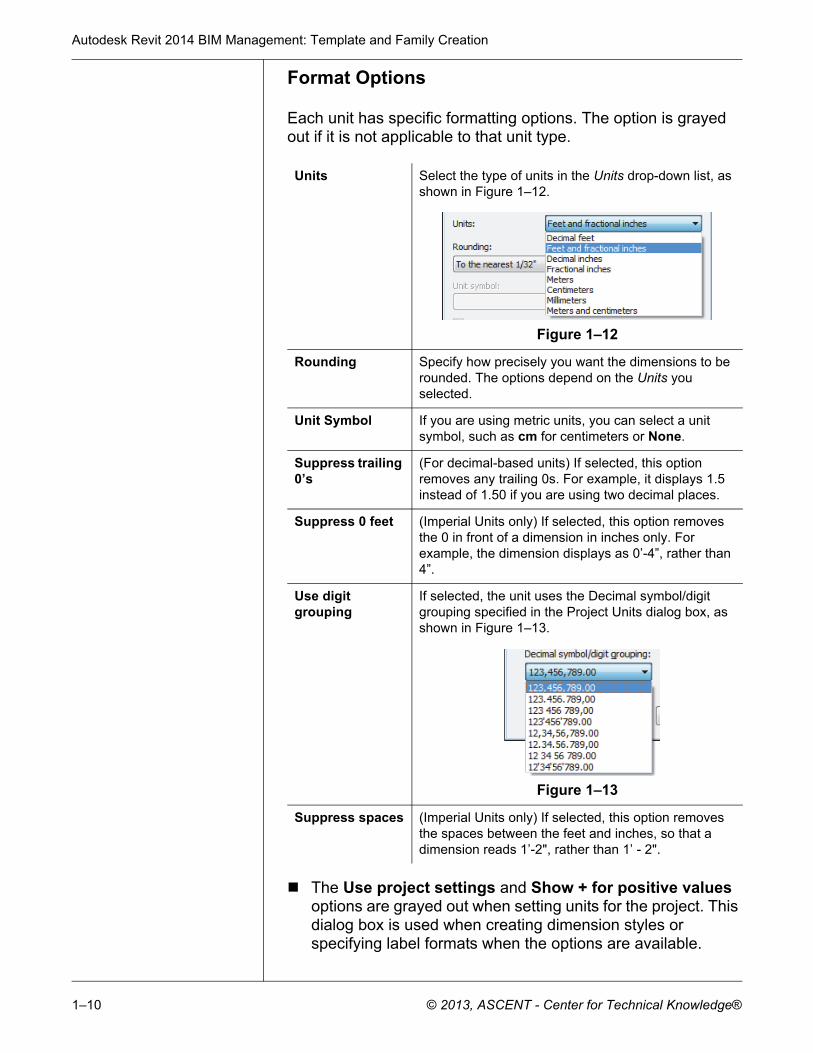
Format Options
Each unit has specific formatting options. The option is grayed out if it is not applicable to that unit type.
The Use project settings and Show + for positive values options are grayed out when setting units for the project. This dialog box is used when creating dimension styles or specifying label formats when the options are available.
Units Select the type of units in the Units drop-down list, as shown in Figure 1–12.
Figure 1–12
Rounding Specify how precisely you want the dimensions to be rounded. The options depend on the Units you selected.
Unit Symbol If you are using metric units, you can select a unit symbol, such as cm for centimeters or None.
Suppress trailing 0’s
(For decimal-based units) If selected, this option removes any trailing 0s. For example, it displays 1.5 instead of 1.50 if you are using two decimal places.
Suppress 0 feet (Imperial Units only) If selected, this option removes the 0 in front of a dimension in inches only. For example, the dimension displays as 0’-4”, rather than 4”.
Use digit grouping
If selected, the unit uses the Decimal symbol/digit grouping specified in the Project Units dialog box, as shown in Figure 1–13.
Figure 1–13
Suppress spaces (Imperial Units only) If selected, this option removes the spaces between the feet and inches, so that a dimension reads 1’-2", rather than 1’ - 2".
Creating Custom Templates
© 2013, ASCENT - Center for Technical Knowledge® 1–11
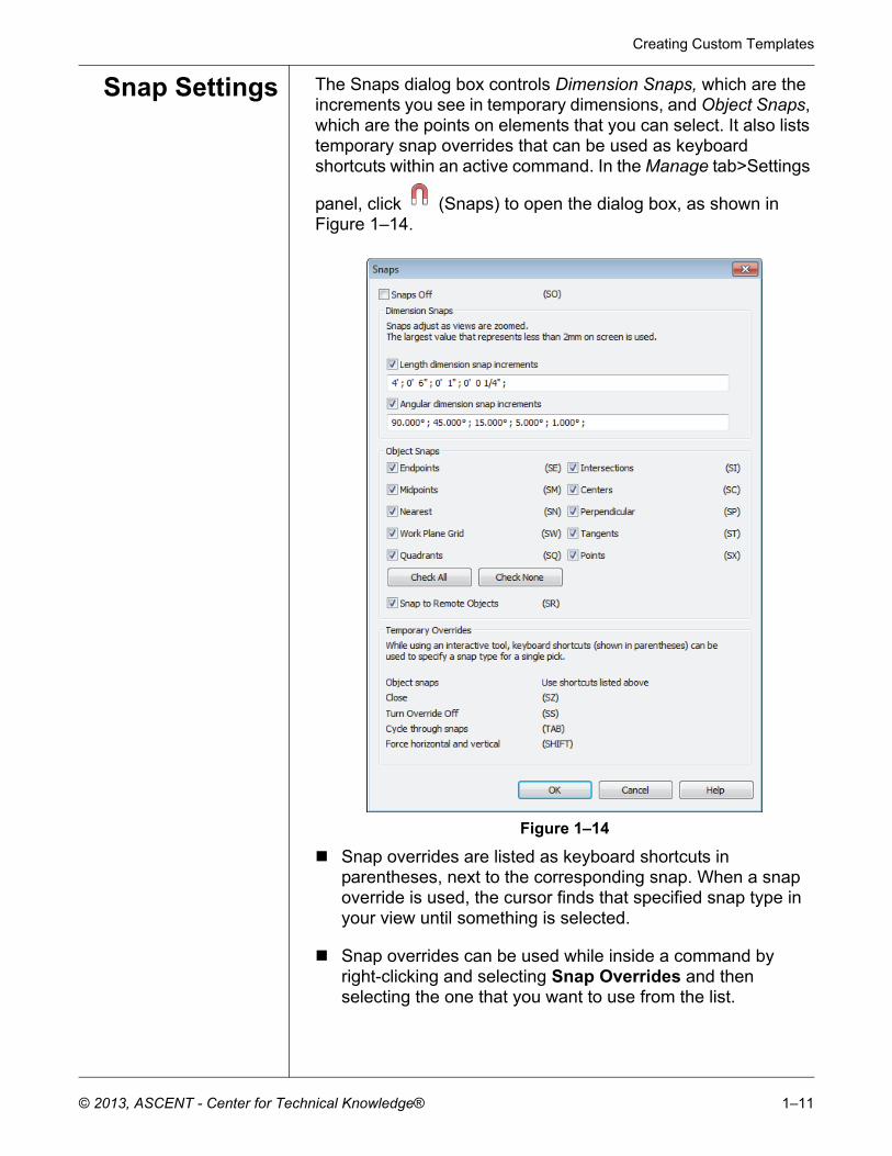
Snap Settings The Snaps dialog box controls Dimension Snaps, which are the increments you see in temporary dimensions, and Object Snaps, which are the points on elements that you can select. It also lists temporary snap overrides that can be used as keyboard shortcuts within an active command. In the Manage tab>Settings
panel, click (Snaps) to open the dialog box, as shown in Figure 1–14.
Figure 1–14
Snap overrides are listed as keyboard shortcuts in parentheses, next to the corresponding snap. When a snap override is used, the cursor finds that specified snap type in your view until something is selected.
Snap overrides can be used while inside a command by right-clicking and selecting Snap Overrides and then selecting the one that you want to use from the list.
Autodesk Revit 2014 BIM Management: Template and Family Creation
1–12 © 2013, ASCENT - Center for Technical Knowledge®
TemporaryDimension
Settings
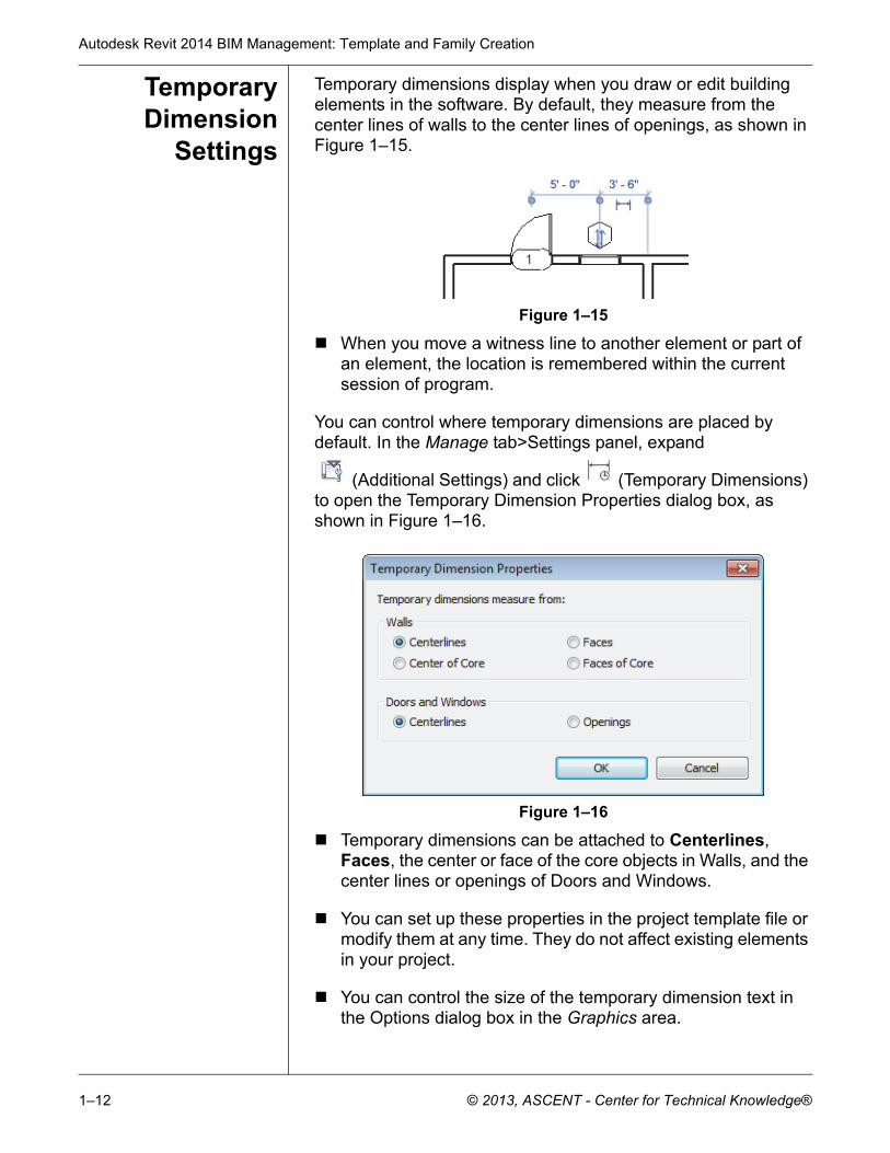
Temporary dimensions display when you draw or edit building elements in the software. By default, they measure from the center lines of walls to the center lines of openings, as shown in Figure 1–15.
Figure 1–15
When you move a witness line to another element or part of an element, the location is remembered within the current session of program.
You can control where temporary dimensions are placed by default. In the Manage tab>Settings panel, expand
(Additional Settings) and click (Temporary Dimensions) to open the Temporary Dimension Properties dialog box, as shown in Figure 1–16.
Figure 1–16
Temporary dimensions can be attached to Centerlines, Faces, the center or face of the core objects in Walls, and the center lines or openings of Doors and Windows.
You can set up these properties in the project template file or modify them at any time. They do not affect existing elements in your project.
You can control the size of the temporary dimension text in the Options dialog box in the Graphics area.
Creating Custom Templates
© 2013, ASCENT - Center for Technical Knowledge® 1–13
1.2 Customizing Annotation Styles
You can customize Annotation styles in your project template file including dimensions, text types, and tags, as shown in Figure 1–17.
Figure 1–17
Text, Dimensions, and Arrowheads are all system families. This means they have a standard set of parameters, which you can modify and save as a type. Callout, Section, and Elevation tags can be modified within the Autodesk Revit software. Most other tags are created using families.
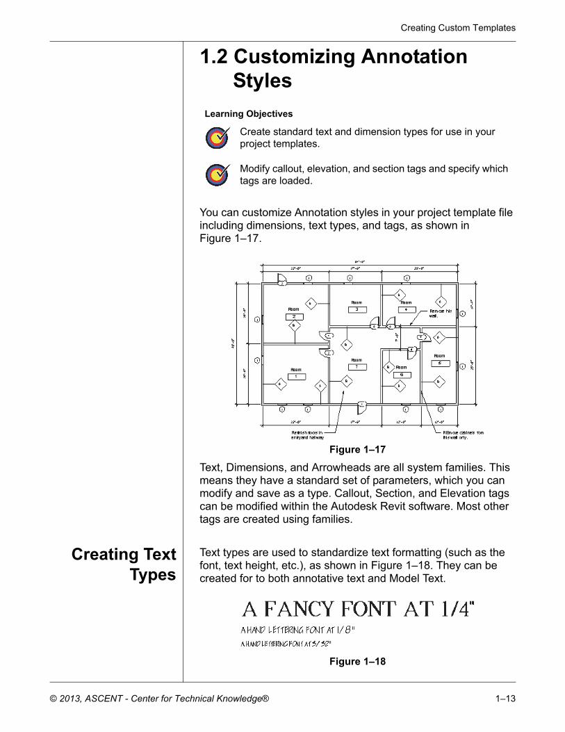
Creating TextTypes
Text types are used to standardize text formatting (such as the font, text height, etc.), as shown in Figure 1–18. They can be created for to both annotative text and Model Text.
Figure 1–18
Learning Objectives
Create standard text and dimension types for use in your project templates.
Modify callout, elevation, and section tags and specify which tags are loaded.
Autodesk Revit 2014 BIM Management: Template and Family Creation
1–14 © 2013, ASCENT - Center for Technical Knowledge®
The Text command places text at the height you need for the final plot. The view scale controls the height of the standard text in the views.
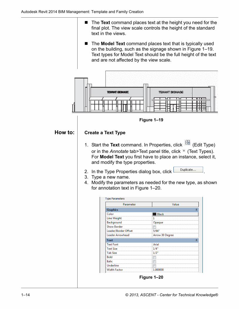
The Model Text command places text that is typically used on the building, such as the signage shown in Figure 1–19. Text types for Model Text should be the full height of the text and are not affected by the view scale.
Figure 1–19
How to: Create a Text Type
1. Start the Text command. In Properties, click (Edit Type) or in the Annotate tab>Text panel title, click (Text Types). For Model Text you first have to place an instance, select it, and modify the type properties.
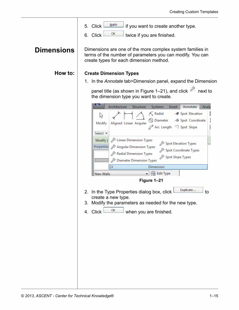
2. In the Type Properties dialog box, click .3. Type a new name.4. Modify the parameters as needed for the new type, as shown
for annotation text in Figure 1–20.
Figure 1–20
Creating Custom Templates
© 2013, ASCENT - Center for Technical Knowledge® 1–15
5. Click if you want to create another type.
6. Click twice if you are finished.
Dimensions Dimensions are one of the more complex system families in terms of the number of parameters you can modify. You can create types for each dimension method.
How to: Create Dimension Types
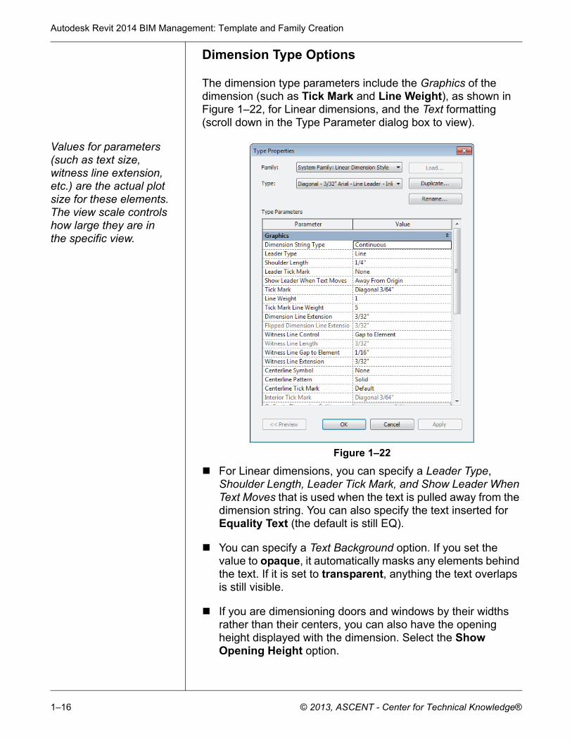
1. In the Annotate tab>Dimension panel, expand the Dimension
panel title (as shown in Figure 1–21), and click next to the dimension type you want to create.
Figure 1–21
2. In the Type Properties dialog box, click to create a new type.
3. Modify the parameters as needed for the new type.
4. Click when you are finished.
Autodesk Revit 2014 BIM Management: Template and Family Creation
1–16 © 2013, ASCENT - Center for Technical Knowledge®
Dimension Type Options
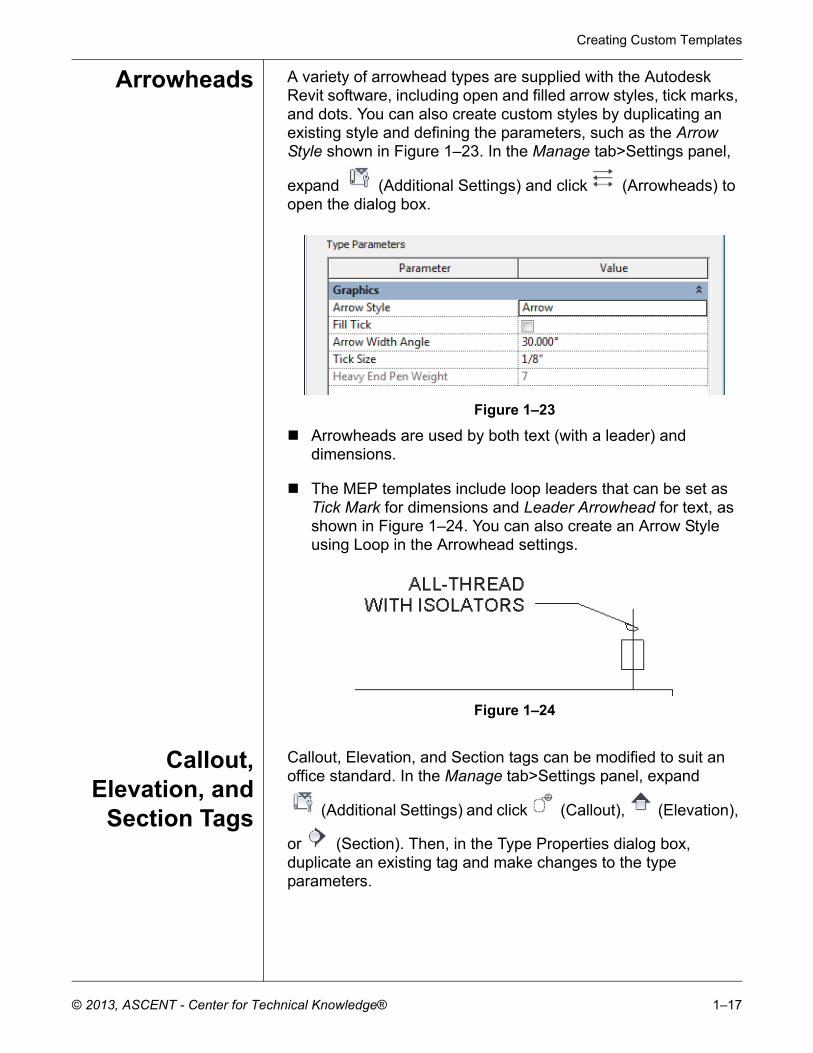
The dimension type parameters include the Graphics of the dimension (such as Tick Mark and Line Weight), as shown in Figure 1–22, for Linear dimensions, and the Text formatting (scroll down in the Type Parameter dialog box to view).
Values for parameters (such as text size, witness line extension, etc.) are the actual plot size for these elements. The view scale controls how large they are in the specific view.
Figure 1–22
For Linear dimensions, you can specify a Leader Type, Shoulder Length, Leader Tick Mark, and Show Leader When Text Moves that is used when the text is pulled away from the dimension string. You can also specify the text inserted for Equality Text (the default is still EQ).
You can specify a Text Background option. If you set the value to opaque, it automatically masks any elements behind the text. If it is set to transparent, anything the text overlaps is still visible.
If you are dimensioning doors and windows by their widths rather than their centers, you can also have the opening height displayed with the dimension. Select the Show Opening Height option.
Creating Custom Templates
© 2013, ASCENT - Center for Technical Knowledge® 1–17
Arrowheads A variety of arrowhead types are supplied with the Autodesk Revit software, including open and filled arrow styles, tick marks, and dots. You can also create custom styles by duplicating an existing style and defining the parameters, such as the Arrow Style shown in Figure 1–23. In the Manage tab>Settings panel,
expand (Additional Settings) and click (Arrowheads) to open the dialog box.
Figure 1–23
Arrowheads are used by both text (with a leader) and dimensions.
The MEP templates include loop leaders that can be set as Tick Mark for dimensions and Leader Arrowhead for text, as shown in Figure 1–24. You can also create an Arrow Style using Loop in the Arrowhead settings.
Figure 1–24
Callout,Elevation, and
Section Tags
Callout, Elevation, and Section tags can be modified to suit an office standard. In the Manage tab>Settings panel, expand
(Additional Settings) and click (Callout), (Elevation),
or (Section). Then, in the Type Properties dialog box, duplicate an existing tag and make changes to the type parameters.

Autodesk Revit 2014 BIM Management: Template and Family Creation
1–18 © 2013, ASCENT - Center for Technical Knowledge®
The Callout Tags parameters specify a Callout Head and the Corner Radius of the callout box, as shown in Figure 1–25.
Figure 1–25
The Elevation Tags parameter is the Elevation Mark. You can select from a variety of types that come with the Autodesk Revit software, as shown in Figure 1–26. For example, you might want to set the exterior elevation mark to display a square body and the detail number on the sheet where it is placed.
Figure 1–26
The Section Tags parameters include both the Section Head and Section Tail, as well as the Broken Section Display Style, as shown in Figure 1–27.
Figure 1–27
Creating Custom Templates
© 2013, ASCENT - Center for Technical Knowledge® 1–19
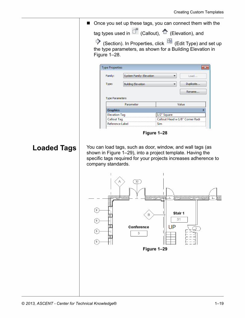
Once you set up these tags, you can connect them with the
tag types used in (Callout), (Elevation), and
(Section). In Properties, click (Edit Type) and set up the type parameters, as shown for a Building Elevation in Figure 1–28.
Figure 1–28
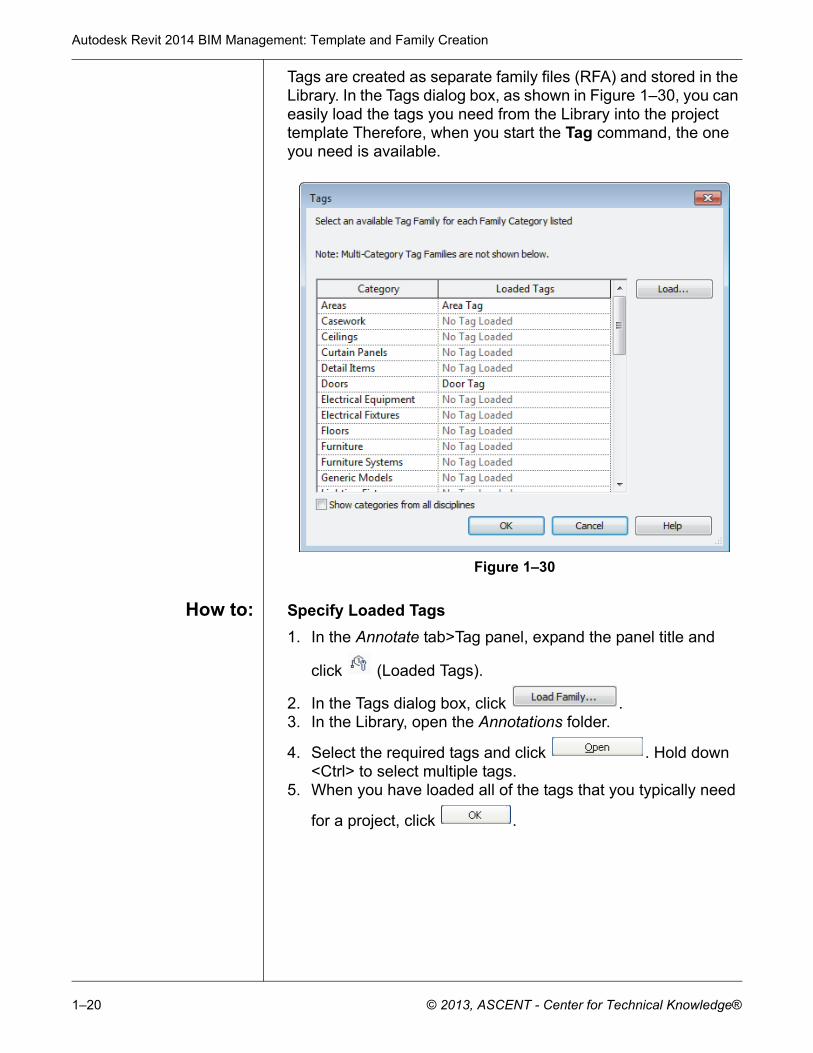
Loaded Tags You can load tags, such as door, window, and wall tags (as shown in Figure 1–29), into a project template. Having the specific tags required for your projects increases adherence to company standards.
Figure 1–29
Autodesk Revit 2014 BIM Management: Template and Family Creation
1–20 © 2013, ASCENT - Center for Technical Knowledge®
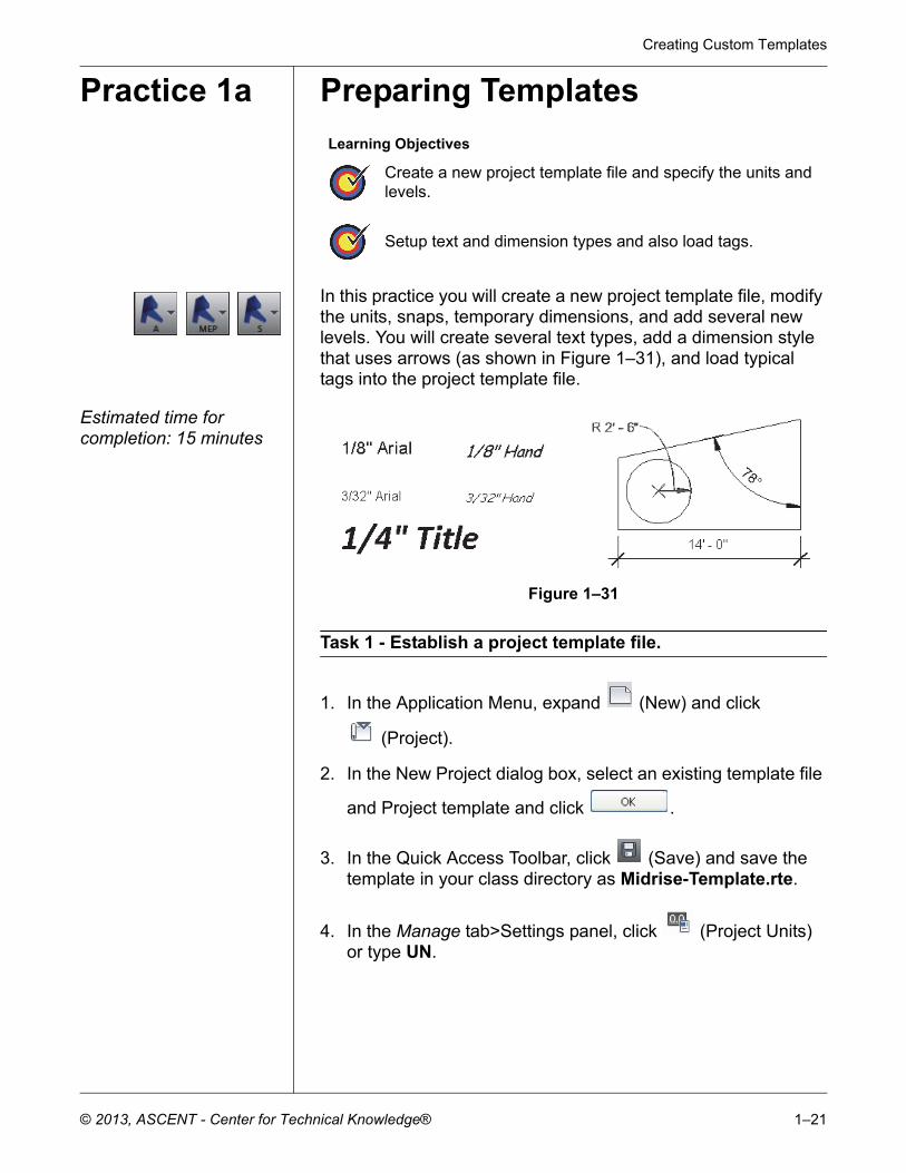
Tags are created as separate family files (RFA) and stored in the Library. In the Tags dialog box, as shown in Figure 1–30, you can easily load the tags you need from the Library into the project template Therefore, when you start the Tag command, the one you need is available.
Figure 1–30
How to: Specify Loaded Tags
1. In the Annotate tab>Tag panel, expand the panel title and
click (Loaded Tags).
2. In the Tags dialog box, click .3. In the Library, open the Annotations folder.
4. Select the required tags and click . Hold down <Ctrl> to select multiple tags.
5. When you have loaded all of the tags that you typically need
for a project, click .
Creating Custom Templates
© 2013, ASCENT - Center for Technical Knowledge® 1–21
Practice 1a Preparing Templates
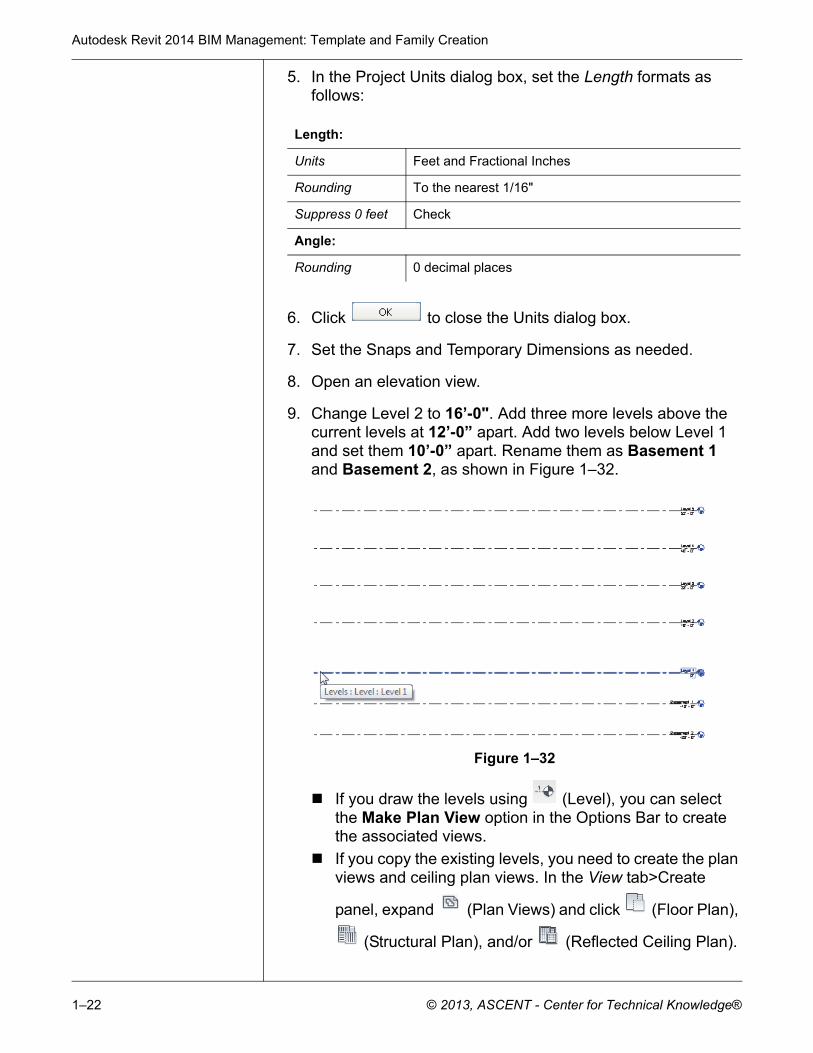
In this practice you will create a new project template file, modify the units, snaps, temporary dimensions, and add several new levels. You will create several text types, add a dimension style that uses arrows (as shown in Figure 1–31), and load typical tags into the project template file.
Estimated time for completion: 15 minutes
Figure 1–31
Task 1 - Establish a project template file.
1. In the Application Menu, expand (New) and click
(Project).
2. In the New Project dialog box, select an existing template file
and Project template and click .
3. In the Quick Access Toolbar, click (Save) and save the template in your class directory as Midrise-Template.rte.
4. In the Manage tab>Settings panel, click (Project Units) or type UN.
Learning Objectives
Create a new project template file and specify the units and levels.
Setup text and dimension types and also load tags.
Autodesk Revit 2014 BIM Management: Template and Family Creation
1–22 © 2013, ASCENT - Center for Technical Knowledge®
5. In the Project Units dialog box, set the Length formats as follows:
6. Click to close the Units dialog box.
7. Set the Snaps and Temporary Dimensions as needed.
8. Open an elevation view.
9. Change Level 2 to 16’-0". Add three more levels above the current levels at 12’-0” apart. Add two levels below Level 1 and set them 10’-0” apart. Rename them as Basement 1 and Basement 2, as shown in Figure 1–32.
Figure 1–32
If you draw the levels using (Level), you can select the Make Plan View option in the Options Bar to create the associated views.
If you copy the existing levels, you need to create the plan views and ceiling plan views. In the View tab>Create
panel, expand (Plan Views) and click (Floor Plan),
(Structural Plan), and/or (Reflected Ceiling Plan).
Length:
Units Feet and Fractional Inches
Rounding To the nearest 1/16"
Suppress 0 feet Check
Angle:
Rounding 0 decimal places
Creating Custom Templates
© 2013, ASCENT - Center for Technical Knowledge® 1–23
Rename above ground levels and corresponding views to match the other levels in the HVAC sub-discipline (3 - Mech, 4 - Mech, etc) and expand the ??? node and select all of the new ceiling plans. In Properties, change the Sub-Discipline to HVAC.
10.Switch back to the original plan view and save the project template.
Task 2 - Preset annotation types.
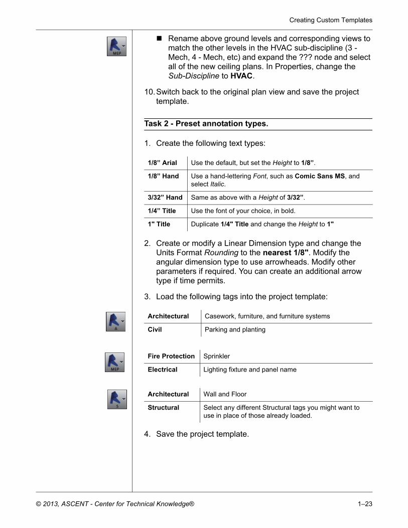
1. Create the following text types:
2. Create or modify a Linear Dimension type and change the Units Format Rounding to the nearest 1/8". Modify the angular dimension type to use arrowheads. Modify other parameters if required. You can create an additional arrow type if time permits.
3. Load the following tags into the project template:
4. Save the project template.
1/8” Arial Use the default, but set the Height to 1/8”.
1/8” Hand Use a hand-lettering Font, such as Comic Sans MS, and select Italic.
3/32” Hand Same as above with a Height of 3/32”.
1/4” Title Use the font of your choice, in bold.
1" Title Duplicate 1/4" Title and change the Height to 1"
Architectural Casework, furniture, and furniture systems
Civil Parking and planting
Fire Protection Sprinkler
Electrical Lighting fixture and panel name
Architectural Wall and Floor
Structural Select any different Structural tags you might want to use in place of those already loaded.
Autodesk Revit 2014 BIM Management: Template and Family Creation
1–24 © 2013, ASCENT - Center for Technical Knowledge®
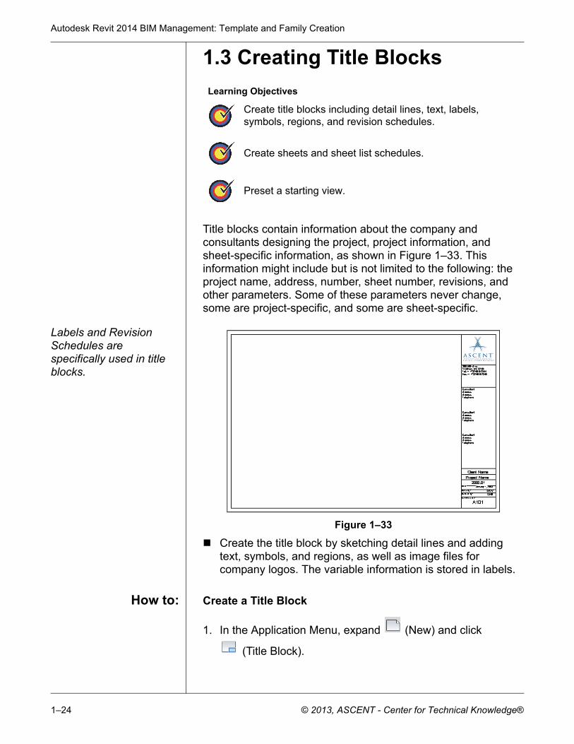
1.3 Creating Title Blocks
Title blocks contain information about the company and consultants designing the project, project information, and sheet-specific information, as shown in Figure 1–33. This information might include but is not limited to the following: the project name, address, number, sheet number, revisions, and other parameters. Some of these parameters never change, some are project-specific, and some are sheet-specific.
Labels and Revision Schedules are specifically used in title blocks.
Figure 1–33
Create the title block by sketching detail lines and adding text, symbols, and regions, as well as image files for company logos. The variable information is stored in labels.
How to: Create a Title Block
1. In the Application Menu, expand (New) and click
(Title Block).
Learning Objectives
Create title blocks including detail lines, text, labels, symbols, regions, and revision schedules.
Create sheets and sheet list schedules.
Preset a starting view.
Creating Custom Templates
© 2013, ASCENT - Center for Technical Knowledge® 1–25
You can select from several preset sizes or create a custom size.
2. In the New Title Block - Select Template File dialog box,
select a template file size from the list and click . A new family file opens and the Family tools display in the Ribbon, as shown in Figure 1–34.
Figure 1–34
If you select a template with a standard size, a rectangle of that size displays in the view.
If you select New Size, a rectangle with dimensions displays. Edit the dimensions to modify the size.
3. Add lines, filled regions, symbols, text, labels, etc., as needed.
4. Save the file and close it.
You can use dimensions to help place the elements in the title block family, they are not displayed when the title block is inserted.
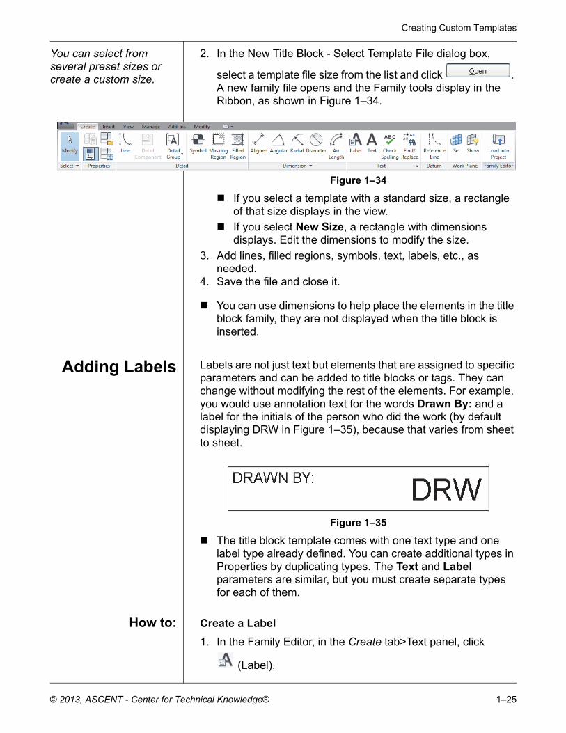
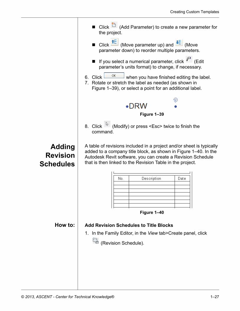
Adding Labels Labels are not just text but elements that are assigned to specific parameters and can be added to title blocks or tags. They can change without modifying the rest of the elements. For example, you would use annotation text for the words Drawn By: and a label for the initials of the person who did the work (by default displaying DRW in Figure 1–35), because that varies from sheet to sheet.
Figure 1–35
The title block template comes with one text type and one label type already defined. You can create additional types in Properties by duplicating types. The Text and Label parameters are similar, but you must create separate types for each of them.
How to: Create a Label
1. In the Family Editor, in the Create tab>Text panel, click
(Label).
Autodesk Revit 2014 BIM Management: Template and Family Creation
1–26 © 2013, ASCENT - Center for Technical Knowledge®
2. In the Modify | Place Label tab>Format panel, specify the alignments: Left, Center, Right, Top, Center Middle, or Bottom, as shown in Figure 1–36.
Figure 1–36
3. Click in the view window to place the label, as shown in Figure 1–37.
Figure 1–37
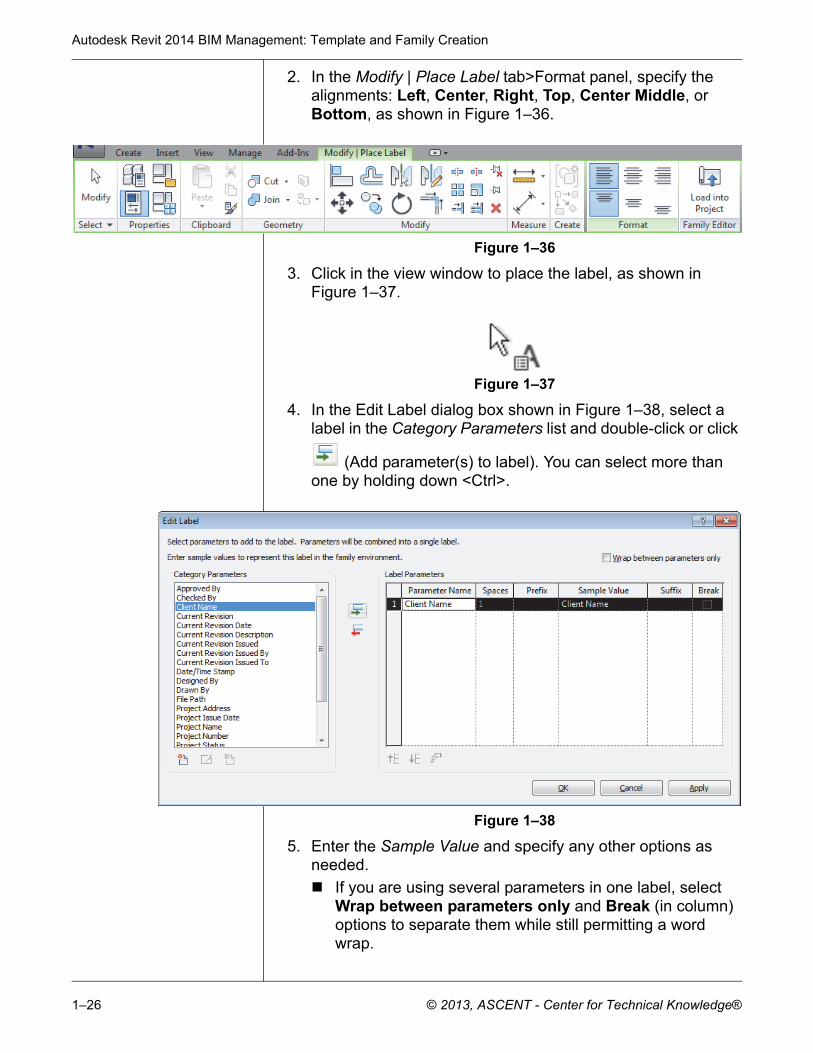
4. In the Edit Label dialog box shown in Figure 1–38, select a label in the Category Parameters list and double-click or click
(Add parameter(s) to label). You can select more than one by holding down <Ctrl>.
Figure 1–38
5. Enter the Sample Value and specify any other options as needed.
If you are using several parameters in one label, select Wrap between parameters only and Break (in column) options to separate them while still permitting a word wrap.
Creating Custom Templates
© 2013, ASCENT - Center for Technical Knowledge® 1–27
Click (Add Parameter) to create a new parameter for the project.
Click (Move parameter up) and (Move parameter down) to reorder multiple parameters.
If you select a numerical parameter, click (Edit parameter’s units format) to change, if necessary.
6. Click when you have finished editing the label.7. Rotate or stretch the label as needed (as shown in
Figure 1–39), or select a point for an additional label.
Figure 1–39
8. Click (Modify) or press <Esc> twice to finish the command.
AddingRevision
Schedules
A table of revisions included in a project and/or sheet is typically added to a company title block, as shown in Figure 1–40. In the Autodesk Revit software, you can create a Revision Schedule that is then linked to the Revision Table in the project.
Figure 1–40
How to: Add Revision Schedules to Title Blocks
1. In the Family Editor, in the View tab>Create panel, click
(Revision Schedule).
Autodesk Revit 2014 BIM Management: Template and Family Creation
1–28 © 2013, ASCENT - Center for Technical Knowledge®
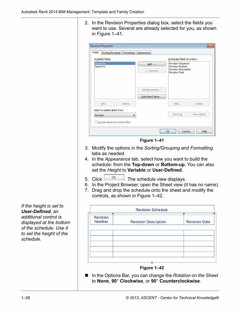
2. In the Revision Properties dialog box, select the fields you want to use. Several are already selected for you, as shown in Figure 1–41.
Figure 1–41
3. Modify the options in the Sorting/Grouping and Formatting tabs as needed.
4. In the Appearance tab, select how you want to build the schedule: from the Top-down or Bottom-up. You can also set the Height to Variable or User-Defined.
5. Click . The schedule view displays.6. In the Project Browser, open the Sheet view (it has no name).7. Drag and drop the schedule onto the sheet and modify the
controls, as shown in Figure 1–42.
If the height is set to User-Defined, an additional control is displayed at the bottom of the schedule. Use it to set the height of the schedule.
Figure 1–42
In the Options Bar, you can change the Rotation on the Sheet to None, 90° Clockwise, or 90° Counterclockwise.
Creating Custom Templates
© 2013, ASCENT - Center for Technical Knowledge® 1–29
Adding Sheetsto ProjectTemplates
You can set up project templates using the custom title block in two ways. Add all or most of the sheets typically needed for a project, or create a Sheet List Schedule that can be used to automatically create sheets when they are needed.
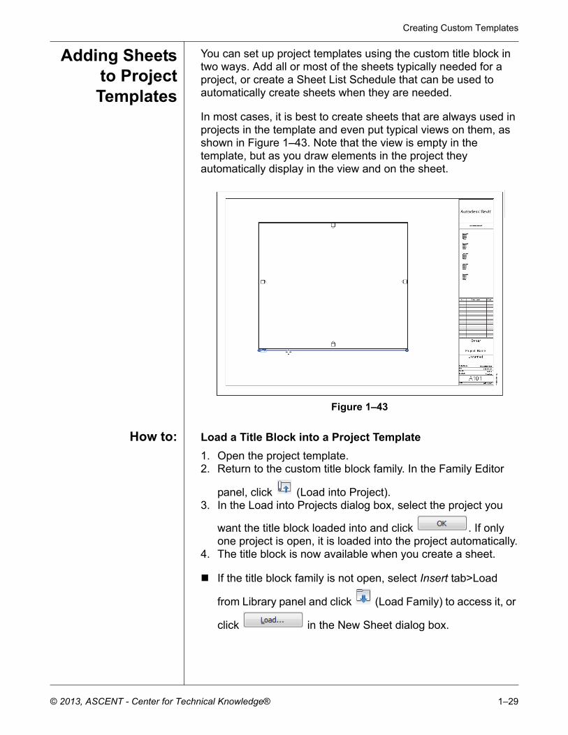
In most cases, it is best to create sheets that are always used in projects in the template and even put typical views on them, as shown in Figure 1–43. Note that the view is empty in the template, but as you draw elements in the project they automatically display in the view and on the sheet.
Figure 1–43
How to: Load a Title Block into a Project Template
1. Open the project template.2. Return to the custom title block family. In the Family Editor
panel, click (Load into Project).3. In the Load into Projects dialog box, select the project you
want the title block loaded into and click . If only one project is open, it is loaded into the project automatically.
4. The title block is now available when you create a sheet.
If the title block family is not open, select Insert tab>Load
from Library panel and click (Load Family) to access it, or
click in the New Sheet dialog box.
Autodesk Revit 2014 BIM Management: Template and Family Creation
1–30 © 2013, ASCENT - Center for Technical Knowledge®
When you save a title block, it should be on the network where everyone has access to it. That way, it is not deleted if someone reinstalls the Autodesk Revit software. Set the default location for the family template files in the Options dialog box, in the File Locations tab, as shown in Figure 1–44.
Figure 1–44
How to: Create a Sheet List Schedule
1. Open a project template file (or a project).
2. In the View tab>Create panel, expand (Schedules) and
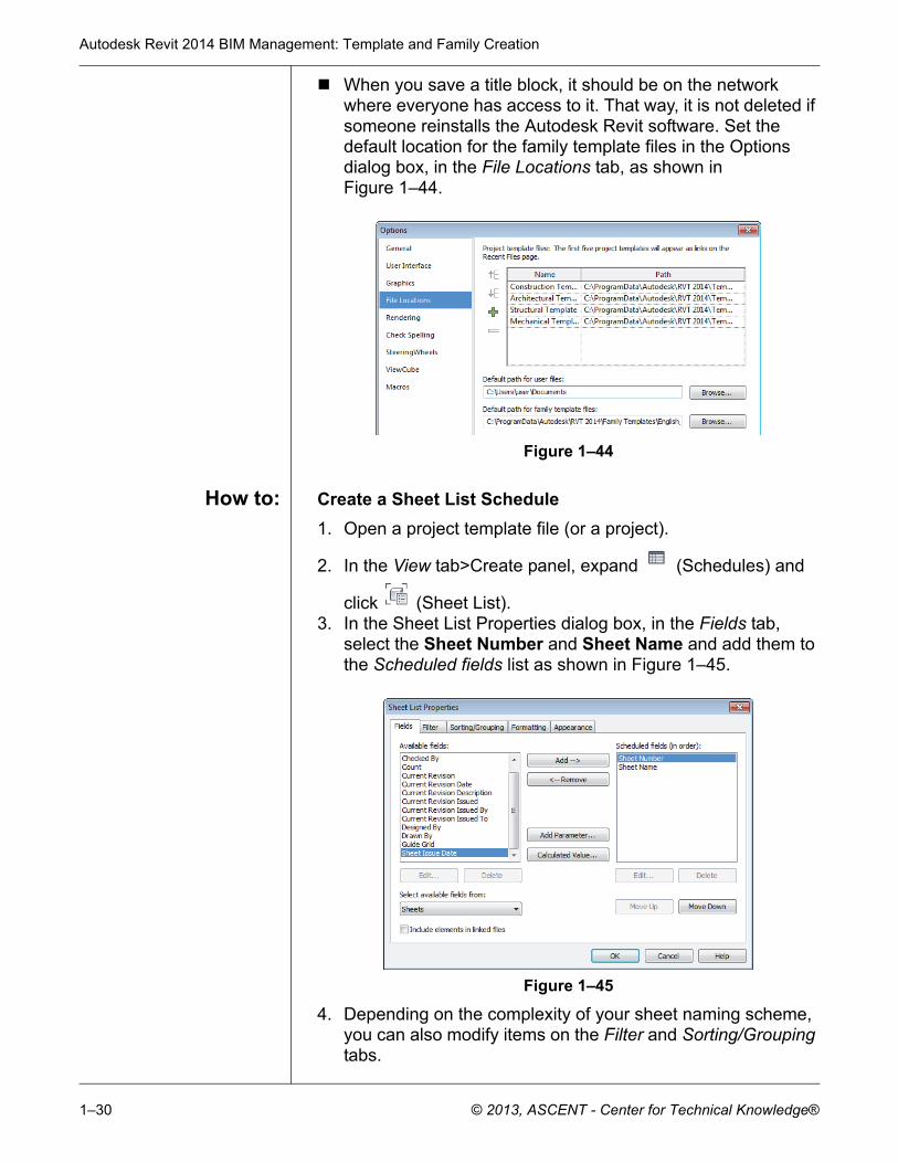
click (Sheet List).3. In the Sheet List Properties dialog box, in the Fields tab,
select the Sheet Number and Sheet Name and add them to the Scheduled fields list as shown in Figure 1–45.
Figure 1–45
4. Depending on the complexity of your sheet naming scheme, you can also modify items on the Filter and Sorting/Grouping tabs.
Creating Custom Templates
© 2013, ASCENT - Center for Technical Knowledge® 1–31
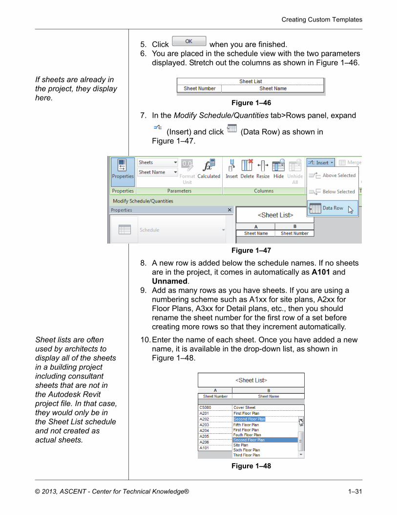
5. Click when you are finished.6. You are placed in the schedule view with the two parameters
displayed. Stretch out the columns as shown in Figure 1–46.
If sheets are already in the project, they display here.
Figure 1–46
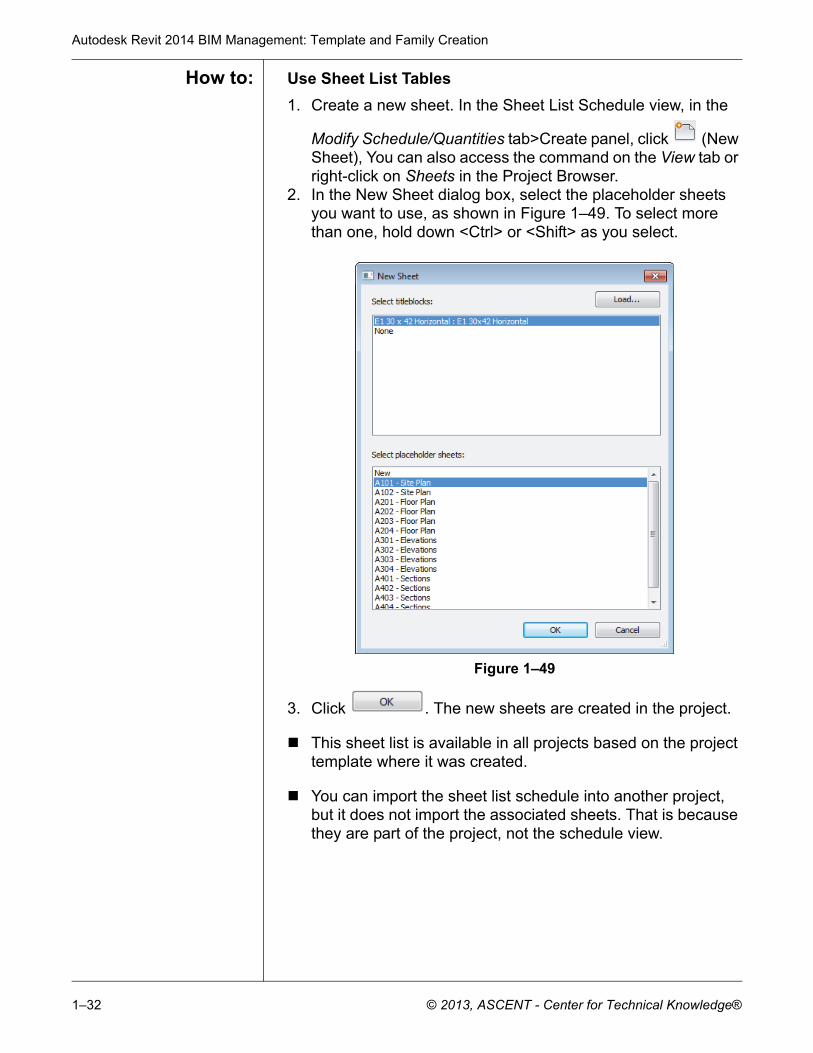
7. In the Modify Schedule/Quantities tab>Rows panel, expand
(Insert) and click (Data Row) as shown in Figure 1–47.
Figure 1–47
8. A new row is added below the schedule names. If no sheets are in the project, it comes in automatically as A101 and Unnamed.
9. Add as many rows as you have sheets. If you are using a numbering scheme such as A1xx for site plans, A2xx for Floor Plans, A3xx for Detail plans, etc., then you should rename the sheet number for the first row of a set before creating more rows so that they increment automatically.
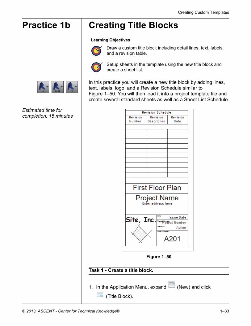
Sheet lists are often used by architects to display all of the sheets in a building project including consultant sheets that are not in the Autodesk Revit project file. In that case, they would only be in the Sheet List schedule and not created as actual sheets.
10.Enter the name of each sheet. Once you have added a new name, it is available in the drop-down list, as shown in Figure 1–48.
Figure 1–48
Autodesk Revit 2014 BIM Management: Template and Family Creation
1–32 © 2013, ASCENT - Center for Technical Knowledge®
How to: Use Sheet List Tables
1. Create a new sheet. In the Sheet List Schedule view, in the
Modify Schedule/Quantities tab>Create panel, click (New Sheet), You can also access the command on the View tab or right-click on Sheets in the Project Browser.
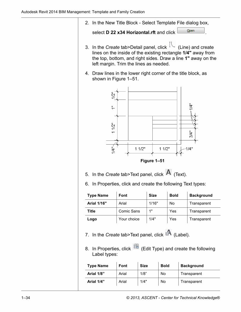
2. In the New Sheet dialog box, select the placeholder sheets you want to use, as shown in Figure 1–49. To select more than one, hold down <Ctrl> or <Shift> as you select.
Figure 1–49
3. Click . The new sheets are created in the project.
This sheet list is available in all projects based on the project template where it was created.
You can import the sheet list schedule into another project, but it does not import the associated sheets. That is because they are part of the project, not the schedule view.
Creating Custom Templates
© 2013, ASCENT - Center for Technical Knowledge® 1–33
Practice 1b Creating Title Blocks
In this practice you will create a new title block by adding lines, text, labels, logo, and a Revision Schedule similar to Figure 1–50. You will then load it into a project template file and create several standard sheets as well as a Sheet List Schedule.
Estimated time for completion: 15 minutes
Figure 1–50
Task 1 - Create a title block.
1. In the Application Menu, expand (New) and click
(Title Block).
Learning Objectives
Draw a custom title block including detail lines, text, labels, and a revision table.
Setup sheets in the template using the new title block and create a sheet list.
Autodesk Revit 2014 BIM Management: Template and Family Creation
1–34 © 2013, ASCENT - Center for Technical Knowledge®
2. In the New Title Block - Select Template File dialog box,
select D 22 x34 Horizontal.rft and click .
3. In the Create tab>Detail panel, click (Line) and create lines on the inside of the existing rectangle 1/4" away from the top, bottom, and right sides. Draw a line 1" away on the left margin. Trim the lines as needed.
4. Draw lines in the lower right corner of the title block, as shown in Figure 1–51.
Figure 1–51
5. In the Create tab>Text panel, click (Text).
6. In Properties, click and create the following Text types:
7. In the Create tab>Text panel, click (Label).
8. In Properties, click (Edit Type) and create the following Label types:
Type Name Font Size Bold Background
Arial 1/16" Arial 1/16" No Transparent
Title Comic Sans 1" Yes Transparent
Logo Your choice 1/4" Yes Transparent
Type Name Font Size Bold Background
Arial 1/8” Arial 1/8” No Transparent
Arial 1/4” Arial 1/4" No Transparent
Creating Custom Templates
© 2013, ASCENT - Center for Technical Knowledge® 1–35
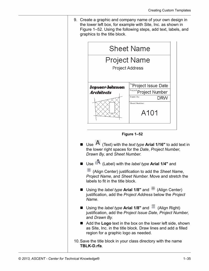
9. Create a graphic and company name of your own design in the lower left box, for example with Site, Inc. as shown in Figure 1–52. Using the following steps, add text, labels, and graphics to the title block.
Figure 1–52
Use (Text) with the text type Arial 1/16" to add text in the lower right spaces for the Date, Project Number, Drawn By, and Sheet Number.
Use (Label) with the label type Arial 1/4" and
(Align Center) justification to add the Sheet Name, Project Name, and Sheet Number. Move and stretch the labels to fit in the title block.
Using the label type Arial 1/8" and (Align Center) justification, add the Project Address below the Project Name.
Using the label type Arial 1/8" and (Align Right) justification, add the Project Issue Date, Project Number, and Drawn By.
Add the Logo text in the box on the lower left side, shown as Site, Inc. in the title block. Draw lines and add a filled region for a graphic logo as needed.
10.Save the title block in your class directory with the name TBLK-D.rfa.
Autodesk Revit 2014 BIM Management: Template and Family Creation
1–36 © 2013, ASCENT - Center for Technical Knowledge®
Task 2 - Add a Revision Schedule.
1. In the title block Family Editor, in the View tab>Create panel,
click (Revision Schedule).
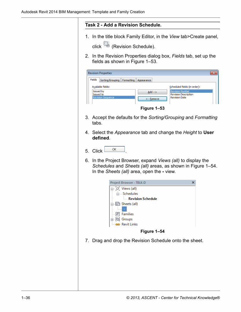
2. In the Revision Properties dialog box, Fields tab, set up the fields as shown in Figure 1–53.
Figure 1–53
3. Accept the defaults for the Sorting/Grouping and Formatting tabs.
4. Select the Appearance tab and change the Height to User defined.
5. Click .
6. In the Project Browser, expand Views (all) to display the Schedules and Sheets (all) areas, as shown in Figure 1–54. In the Sheets (all) area, open the - view.
Figure 1–54
7. Drag and drop the Revision Schedule onto the sheet.
Creating Custom Templates
© 2013, ASCENT - Center for Technical Knowledge® 1–37
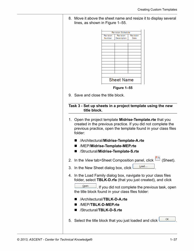
8. Move it above the sheet name and resize it to display several lines, as shown in Figure 1–55.
Figure 1–55
9. Save and close the title block.
Task 3 - Set up sheets in a project template using the new title block.
1. Open the project template Midrise-Template.rte that you created in the previous practice. If you did not complete the previous practice, open the template found in your class files folder:
/Architectural/Midrise-Template-A.rte
/MEP/Midrise-Template-MEP.rte
/Structural/Midrise-Template-S.rte
2. In the View tab>Sheet Composition panel, click (Sheet).
3. In the New Sheet dialog box, click .
4. In the Load Family dialog box, navigate to your class files folder, select TBLK-D.rfa (that you just created), and click
. If you did not complete the previous task, open the title block found in your class files folder:
/Architectural/TBLK-D-A.rte
/MEP/TBLK-D-MEP.rte
/Structural/TBLK-D-S.rte
5. Select the title block that you just loaded and click .
Autodesk Revit 2014 BIM Management: Template and Family Creation
1–38 © 2013, ASCENT - Center for Technical Knowledge®
6. In the Project Browser, select the sheet and rename it asCS000 – Cover Sheet.
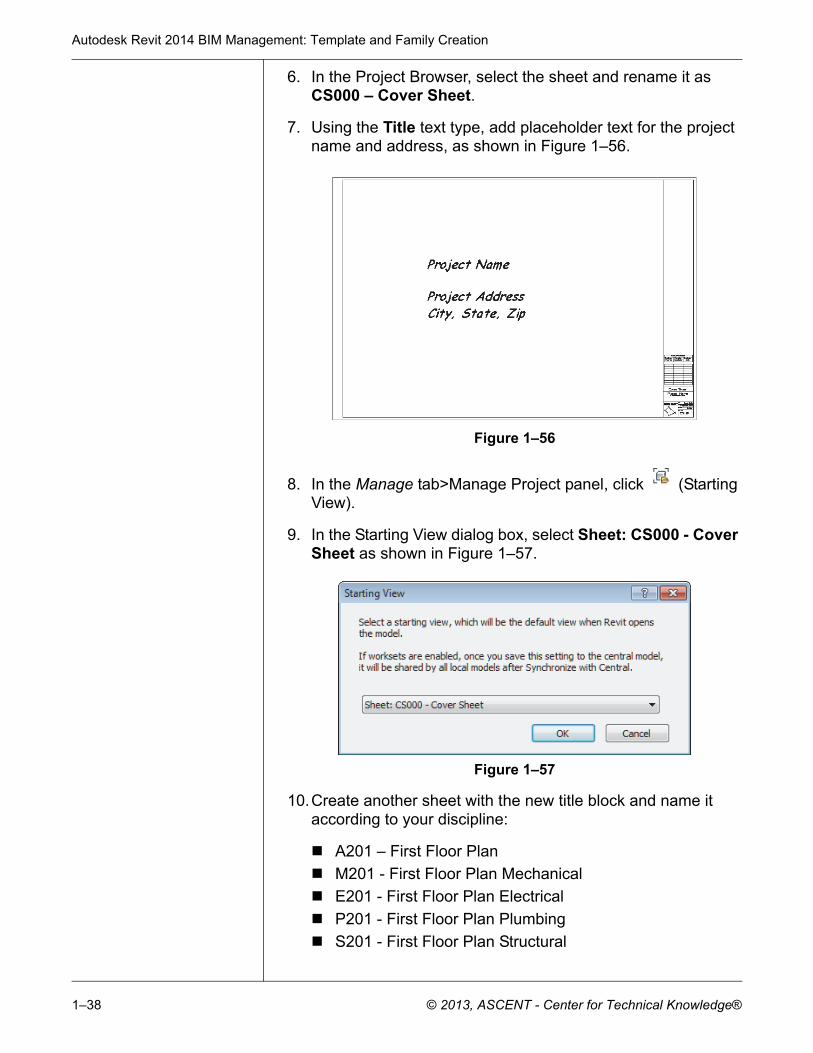
7. Using the Title text type, add placeholder text for the project name and address, as shown in Figure 1–56.
Figure 1–56
8. In the Manage tab>Manage Project panel, click (Starting View).
9. In the Starting View dialog box, select Sheet: CS000 - Cover Sheet as shown in Figure 1–57.
Figure 1–57
10.Create another sheet with the new title block and name it according to your discipline:
A201 – First Floor Plan
M201 - First Floor Plan Mechanical
E201 - First Floor Plan Electrical
P201 - First Floor Plan Plumbing
S201 - First Floor Plan Structural
Creating Custom Templates
© 2013, ASCENT - Center for Technical Knowledge® 1–39
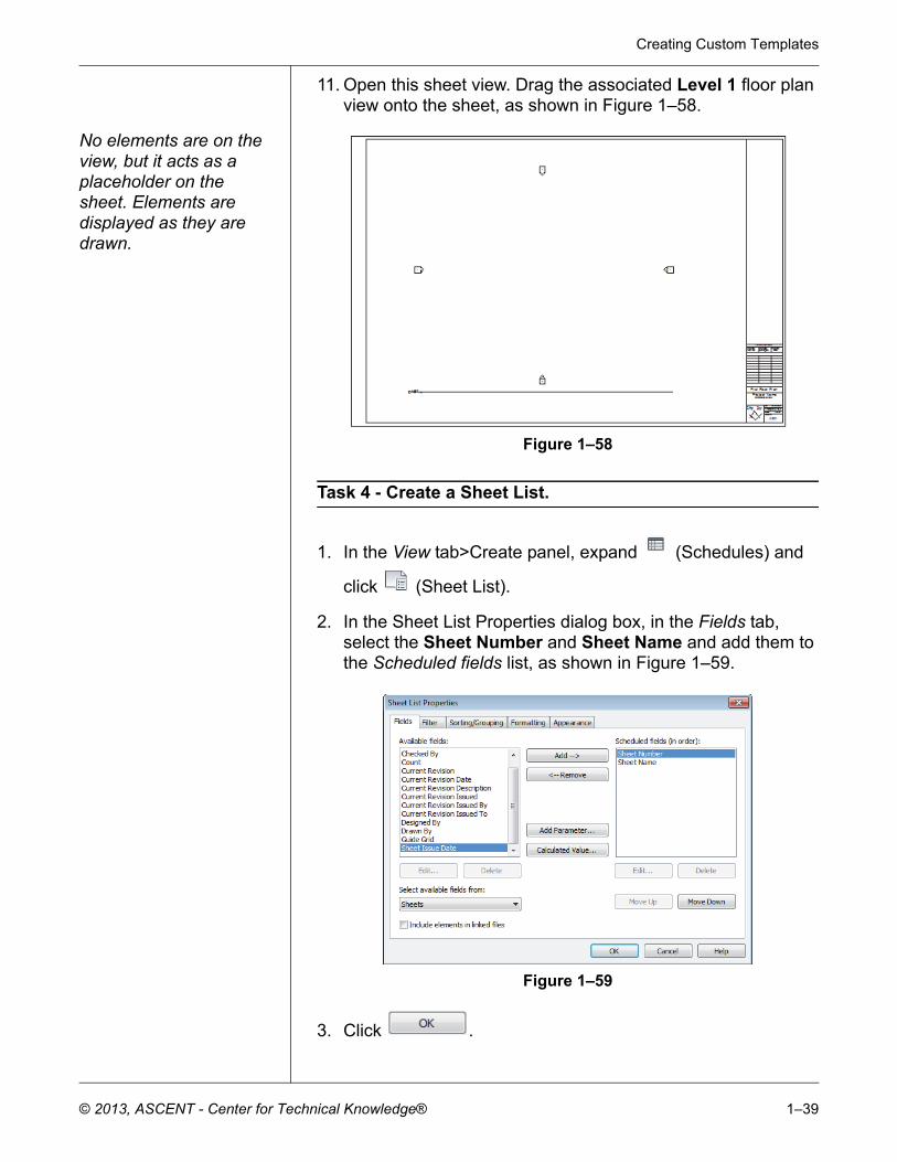
11. Open this sheet view. Drag the associated Level 1 floor plan view onto the sheet, as shown in Figure 1–58.
No elements are on the view, but it acts as a placeholder on the sheet. Elements are displayed as they are drawn.
Figure 1–58
Task 4 - Create a Sheet List.
1. In the View tab>Create panel, expand (Schedules) and
click (Sheet List).
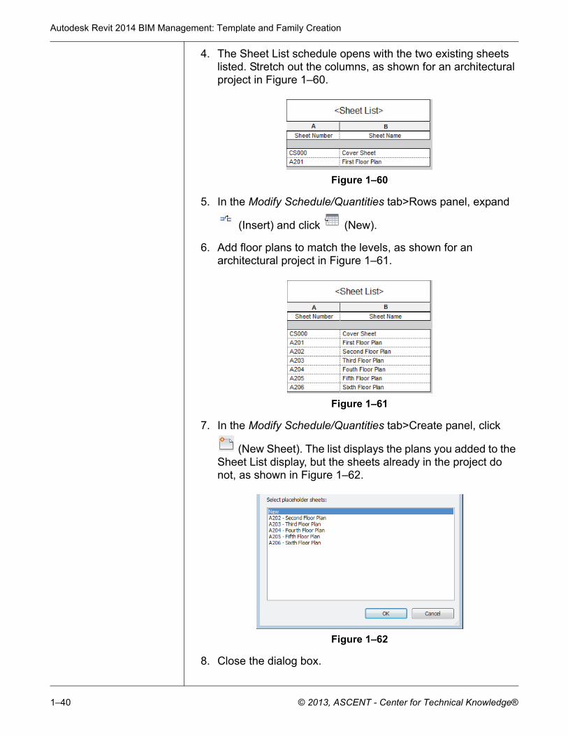
2. In the Sheet List Properties dialog box, in the Fields tab, select the Sheet Number and Sheet Name and add them to the Scheduled fields list, as shown in Figure 1–59.
Figure 1–59
3. Click .
Autodesk Revit 2014 BIM Management: Template and Family Creation
1–40 © 2013, ASCENT - Center for Technical Knowledge®
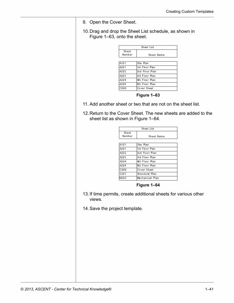
4. The Sheet List schedule opens with the two existing sheets listed. Stretch out the columns, as shown for an architectural project in Figure 1–60.
Figure 1–60
5. In the Modify Schedule/Quantities tab>Rows panel, expand
(Insert) and click (New).
6. Add floor plans to match the levels, as shown for an architectural project in Figure 1–61.
Figure 1–61
7. In the Modify Schedule/Quantities tab>Create panel, click
(New Sheet). The list displays the plans you added to the Sheet List display, but the sheets already in the project do not, as shown in Figure 1–62.
Figure 1–62
8. Close the dialog box.
Creating Custom Templates
© 2013, ASCENT - Center for Technical Knowledge® 1–41
9. Open the Cover Sheet.
10.Drag and drop the Sheet List schedule, as shown in Figure 1–63, onto the sheet.
Figure 1–63
11. Add another sheet or two that are not on the sheet list.
12.Return to the Cover Sheet. The new sheets are added to the sheet list as shown in Figure 1–64.
Figure 1–64
13. If time permits, create additional sheets for various other views.
14.Save the project template.
Autodesk Revit 2014 BIM Management: Template and Family Creation
1–42 © 2013, ASCENT - Center for Technical Knowledge®
1.4 View Templates
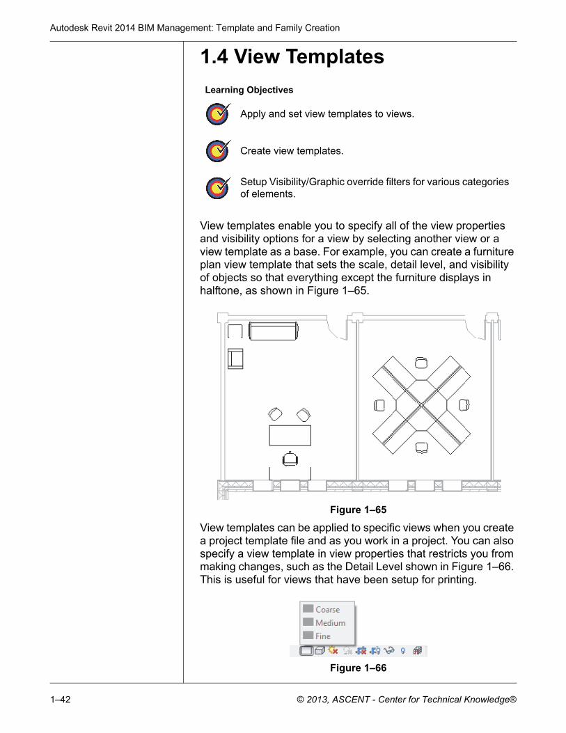
View templates enable you to specify all of the view properties and visibility options for a view by selecting another view or a view template as a base. For example, you can create a furniture plan view template that sets the scale, detail level, and visibility of objects so that everything except the furniture displays in halftone, as shown in Figure 1–65.
Figure 1–65
View templates can be applied to specific views when you create a project template file and as you work in a project. You can also specify a view template in view properties that restricts you from making changes, such as the Detail Level shown in Figure 1–66. This is useful for views that have been setup for printing.
Figure 1–66
Learning Objectives
Apply and set view templates to views.
Create view templates.
Setup Visibility/Graphic override filters for various categories of elements.
Creating Custom Templates
© 2013, ASCENT - Center for Technical Knowledge® 1–43
Applying ViewTemplates
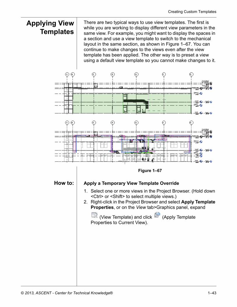
There are two typical ways to use view templates. The first is while you are working to display different view parameters in the same view. For example, you might want to display the spaces in a section and use a view template to switch to the mechanical layout in the same section, as shown in Figure 1–67. You can continue to make changes to the views even after the view template has been applied. The other way is to preset a view using a default view template so you cannot make changes to it.
Figure 1–67
How to: Apply a Temporary View Template Override
1. Select one or more views in the Project Browser. (Hold down <Ctrl> or <Shift> to select multiple views.)
2. Right-click in the Project Browser and select Apply Template Properties, or on the View tab>Graphics panel, expand
(View Template) and click (Apply Template Properties to Current View).
Autodesk Revit 2014 BIM Management: Template and Family Creation
1–44 © 2013, ASCENT - Center for Technical Knowledge®
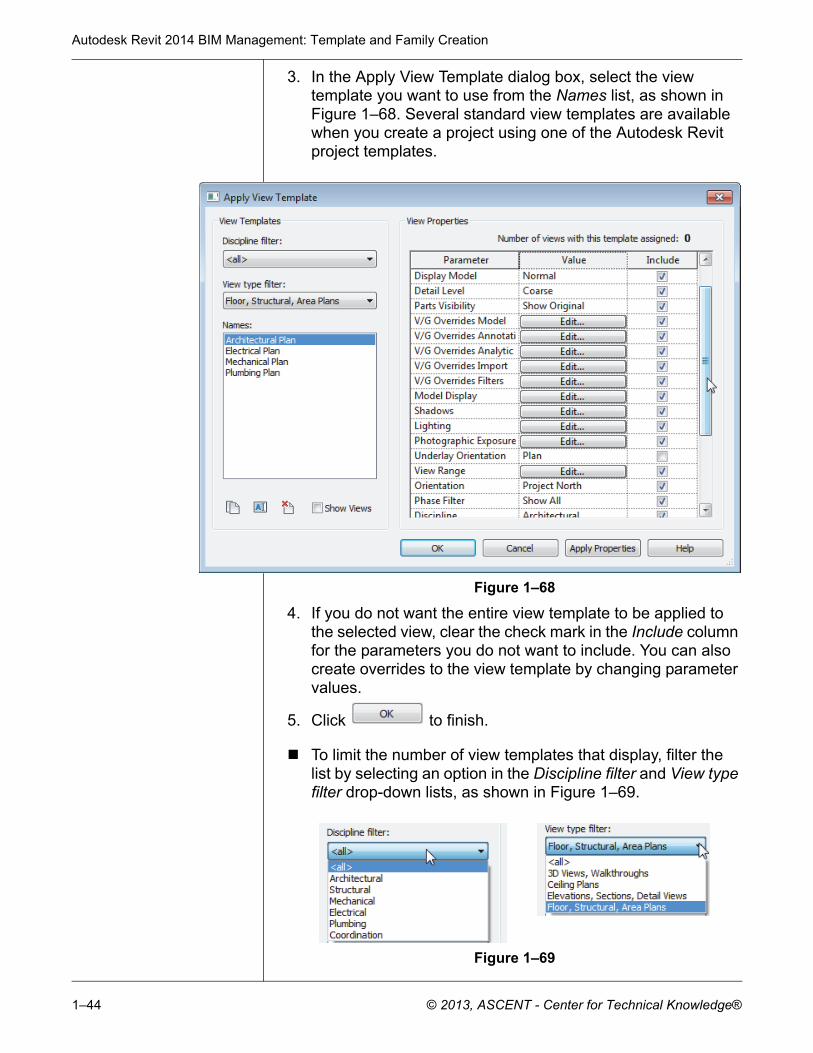
3. In the Apply View Template dialog box, select the view template you want to use from the Names list, as shown in Figure 1–68. Several standard view templates are available when you create a project using one of the Autodesk Revit project templates.
Figure 1–68
4. If you do not want the entire view template to be applied to the selected view, clear the check mark in the Include column for the parameters you do not want to include. You can also create overrides to the view template by changing parameter values.
5. Click to finish.
To limit the number of view templates that display, filter the list by selecting an option in the Discipline filter and View type filter drop-down lists, as shown in Figure 1–69.
Figure 1–69
Creating Custom Templates
© 2013, ASCENT - Center for Technical Knowledge® 1–45
You can apply view templates to any view as many times as needed only if it is not set as the default template in the view properties.
How to: Set the Default View Template for a View
1. Select one or more views in the Project Browser. (Hold down <Ctrl> or <Shift> to select multiple views.)
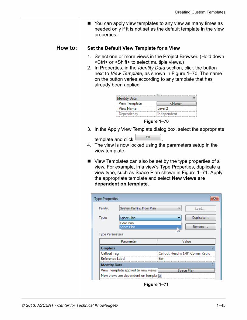
2. In Properties, in the Identity Data section, click the button next to View Template, as shown in Figure 1–70. The name on the button varies according to any template that has already been applied.
Figure 1–70
3. In the Apply View Template dialog box, select the appropriate
template and click .4. The view is now locked using the parameters setup in the
view template.
View Templates can also be set by the type properties of a view. For example, in a view’s Type Properties, duplicate a view type, such as Space Plan shown in Figure 1–71. Apply the appropriate template and select New views are dependent on template.
Figure 1–71
Autodesk Revit 2014 BIM Management: Template and Family Creation
1–46 © 2013, ASCENT - Center for Technical Knowledge®
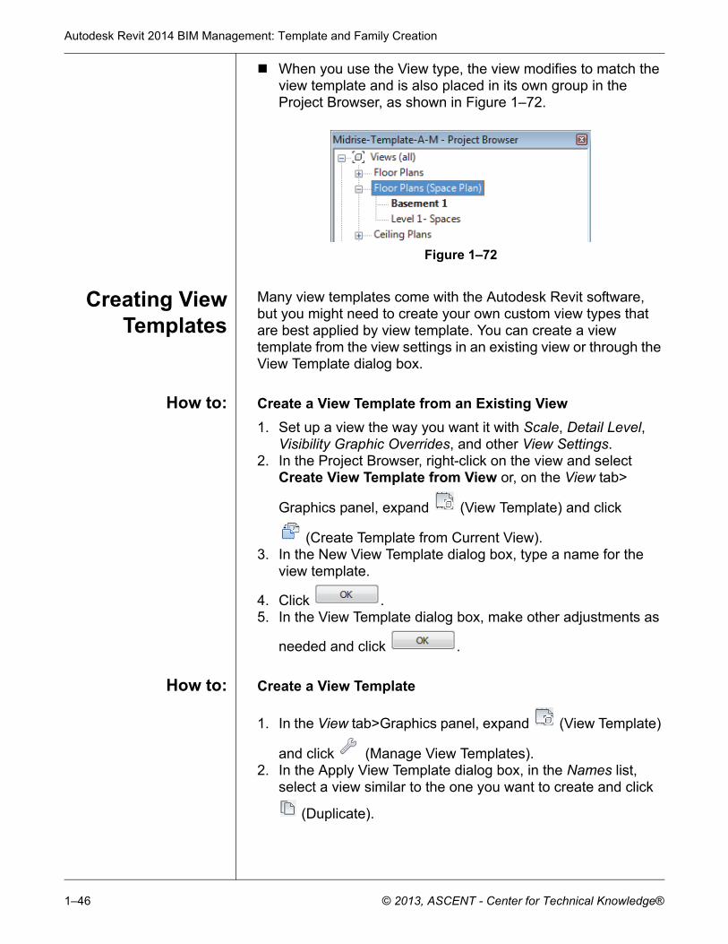
When you use the View type, the view modifies to match the view template and is also placed in its own group in the Project Browser, as shown in Figure 1–72.
Figure 1–72
Creating ViewTemplates
Many view templates come with the Autodesk Revit software, but you might need to create your own custom view types that are best applied by view template. You can create a view template from the view settings in an existing view or through the View Template dialog box.
How to: Create a View Template from an Existing View
1. Set up a view the way you want it with Scale, Detail Level, Visibility Graphic Overrides, and other View Settings.
2. In the Project Browser, right-click on the view and select Create View Template from View or, on the View tab>
Graphics panel, expand (View Template) and click
(Create Template from Current View).3. In the New View Template dialog box, type a name for the
view template.
4. Click .5. In the View Template dialog box, make other adjustments as
needed and click .
How to: Create a View Template
1. In the View tab>Graphics panel, expand (View Template)
and click (Manage View Templates). 2. In the Apply View Template dialog box, in the Names list,
select a view similar to the one you want to create and click
(Duplicate).

Creating Custom Templates
© 2013, ASCENT - Center for Technical Knowledge® 1–47
3. In the New View Template dialog box, type a new name for
the view template and click .4. Select the new view template as shown in Figure 1–73, and
modify the View Properties parameter values as needed.
Figure 1–73
5. Click to finish.
Not all view types have the same view parameters. For example, 3D views have options for Rendering and Perspectives that plans do not have. When you apply a view template across view types, only the options that are mutual are updated.
If you want to start a new view template based on an existing view, select Show Views. The Names list expands to include all of the related views in the project.
Autodesk Revit 2014 BIM Management: Template and Family Creation
1–48 © 2013, ASCENT - Center for Technical Knowledge®
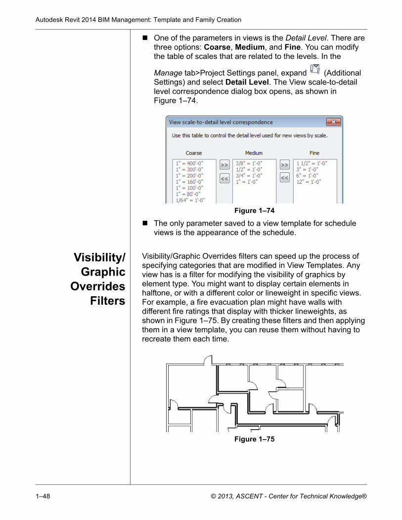
One of the parameters in views is the Detail Level. There are three options: Coarse, Medium, and Fine. You can modify the table of scales that are related to the levels. In the
Manage tab>Project Settings panel, expand (Additional Settings) and select Detail Level. The View scale-to-detail level correspondence dialog box opens, as shown in Figure 1–74.
Figure 1–74
The only parameter saved to a view template for schedule views is the appearance of the schedule.
Visibility/Graphic
OverridesFilters
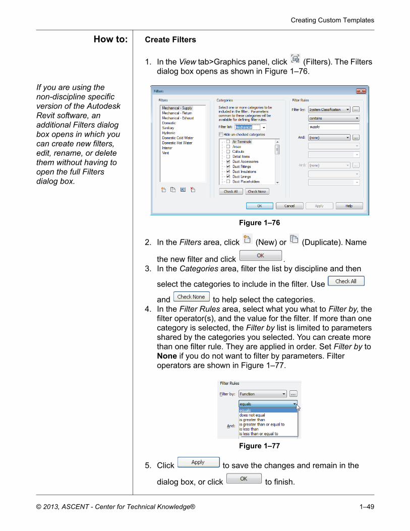
Visibility/Graphic Overrides filters can speed up the process of specifying categories that are modified in View Templates. Any view has is a filter for modifying the visibility of graphics by element type. You might want to display certain elements in halftone, or with a different color or lineweight in specific views. For example, a fire evacuation plan might have walls with different fire ratings that display with thicker lineweights, as shown in Figure 1–75. By creating these filters and then applying them in a view template, you can reuse them without having to recreate them each time.
Figure 1–75
Creating Custom Templates
© 2013, ASCENT - Center for Technical Knowledge® 1–49
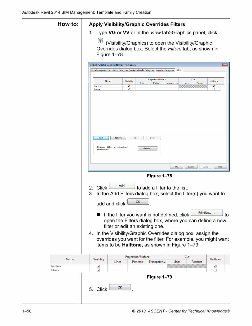
How to: Create Filters
1. In the View tab>Graphics panel, click (Filters). The Filters dialog box opens as shown in Figure 1–76.
If you are using the non-discipline specific version of the Autodesk Revit software, an additional Filters dialog box opens in which you can create new filters, edit, rename, or delete them without having to open the full Filters dialog box.
Figure 1–76
2. In the Filters area, click (New) or (Duplicate). Name
the new filter and click .3. In the Categories area, filter the list by discipline and then
select the categories to include in the filter. Use
and to help select the categories.4. In the Filter Rules area, select what you what to Filter by, the
filter operator(s), and the value for the filter. If more than one category is selected, the Filter by list is limited to parameters shared by the categories you selected. You can create more than one filter rule. They are applied in order. Set Filter by to None if you do not want to filter by parameters. Filter operators are shown in Figure 1–77.
Figure 1–77
5. Click to save the changes and remain in the
dialog box, or click to finish.
Autodesk Revit 2014 BIM Management: Template and Family Creation
1–50 © 2013, ASCENT - Center for Technical Knowledge®
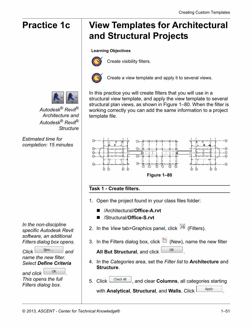
How to: Apply Visibility/Graphic Overrides Filters
1. Type VG or VV or in the View tab>Graphics panel, click
(Visibility/Graphics) to open the Visibility/Graphic Overrides dialog box. Select the Filters tab, as shown in Figure 1–78.
Figure 1–78
2. Click to add a filter to the list.3. In the Add Filters dialog box, select the filter(s) you want to
add and click .
If the filter you want is not defined, click to open the Filters dialog box, where you can define a new filter or edit an existing one.
4. In the Visibility/Graphic Overrides dialog box, assign the overrides you want for the filter. For example, you might want items to be Halftone, as shown in Figure 1–79.
Figure 1–79
5. Click .
Creating Custom Templates
© 2013, ASCENT - Center for Technical Knowledge® 1–51
Practice 1c View Templates for Architectural and Structural Projects
Autodesk® Revit®
Architecture and
Autodesk® Revit®
Structure
In this practice you will create filters that you will use in a structural view template, and apply the view template to several structural plan views, as shown in Figure 1–80. When the filter is working correctly you can add the same information to a project template file.
Estimated time for completion: 15 minutes
Figure 1–80
Task 1 - Create filters.
1. Open the project found in your class files folder:
/Architectural/Office-A.rvt
/Structural/Office-S.rvt
In the non-discipline specific Autodesk Revit software, an additional Filters dialog box opens.
Click and name the new filter. Select Define Criteria
and click . This opens the full Filters dialog box.
2. In the View tab>Graphics panel, click (Filters).
3. In the Filters dialog box, click (New), name the new filter
All But Structural, and click .
4. In the Categories area, set the Filter list to Architecture and Structure.
5. Click , and clear Columns, all categories starting
with Analytical, Structural, and Walls. Click .
Learning Objectives
Create visibility filters.
Create a view template and apply it to several views.
Autodesk Revit 2014 BIM Management: Template and Family Creation
1–52 © 2013, ASCENT - Center for Technical Knowledge®
6. Click (New). Name the new filter Non-Structural Walls
and click .
7. In the Categories area, click and select Walls.
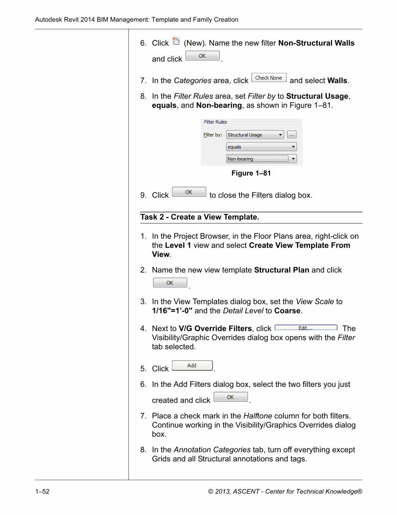
8. In the Filter Rules area, set Filter by to Structural Usage, equals, and Non-bearing, as shown in Figure 1–81.
Figure 1–81
9. Click to close the Filters dialog box.
Task 2 - Create a View Template.
1. In the Project Browser, in the Floor Plans area, right-click on the Level 1 view and select Create View Template From View.
2. Name the new view template Structural Plan and click
.
3. In the View Templates dialog box, set the View Scale to 1/16"=1’-0" and the Detail Level to Coarse.
4. Next to V/G Override Filters, click The Visibility/Graphic Overrides dialog box opens with the Filter tab selected.
5. Click .
6. In the Add Filters dialog box, select the two filters you just
created and click .
7. Place a check mark in the Halftone column for both filters. Continue working in the Visibility/Graphics Overrides dialog box.
8. In the Annotation Categories tab, turn off everything except Grids and all Structural annotations and tags.
Creating Custom Templates
© 2013, ASCENT - Center for Technical Knowledge® 1–53
9. In the Model Categories tab, turn off items, such as Casework, Furniture, Furniture Systems and Plumbing, and Mechanical equipment.
10.Click to close the Visibility/Graphic Overrides
dialog box, and click to complete the view template.
Task 3 - Apply a View Template to several views.
1. In the Floor Plans area, use Duplicate with Detailing on the Level 1, Level 2, Level 3, and Level 4 views. Rename them as Structural – Level 1, Structural – Level 2, Structural – Level 3, and Structural – Level 4.
2. Select the new Structural views.
3. Right-click and select Apply View Template.
4. In the Apply View Template dialog box, select the Structural
Plan view template you just created and click to apply it.
5. Look at the different views and compare them to the standard floor plan views. Finish with the Level 1 view.
6. Save the project.
Autodesk Revit 2014 BIM Management: Template and Family Creation
1–54 © 2013, ASCENT - Center for Technical Knowledge®
Practice 1d View Templates for MEP Projects
Autodesk Revit MEP only
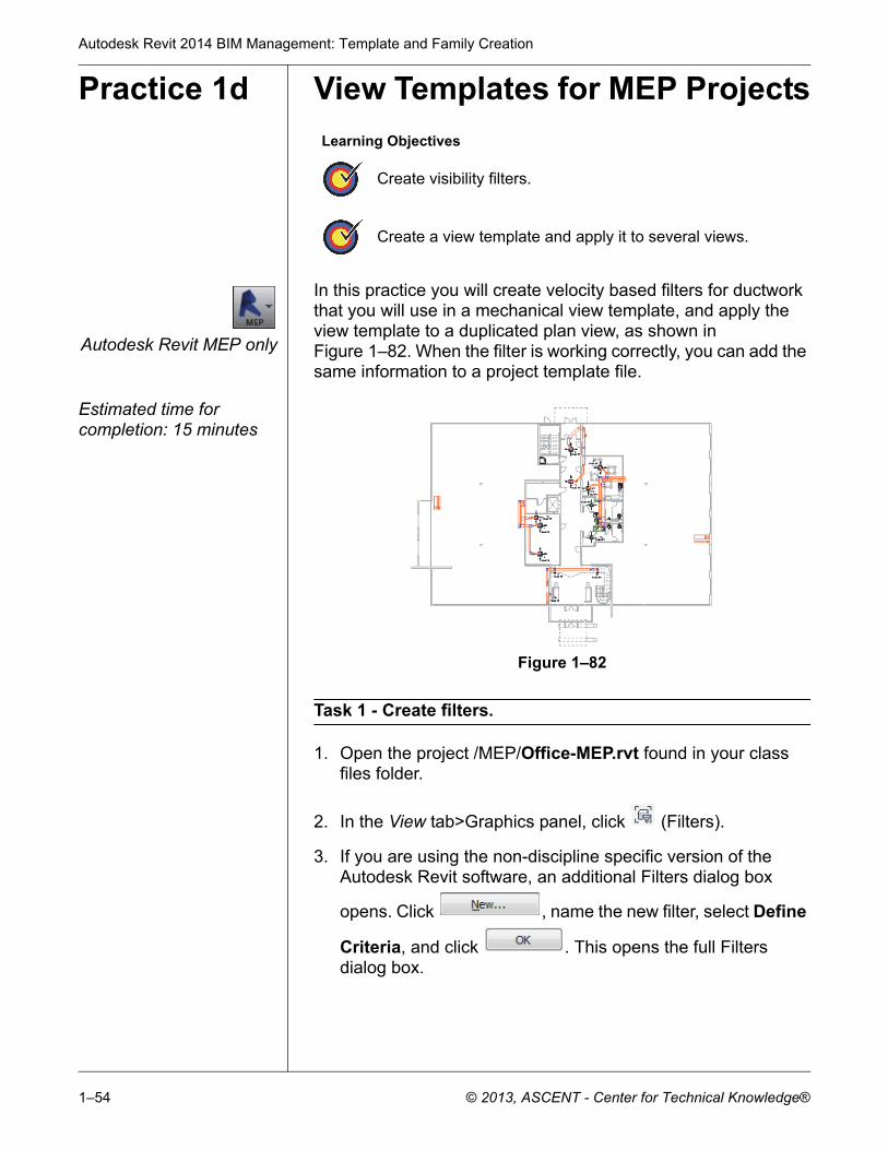
In this practice you will create velocity based filters for ductwork that you will use in a mechanical view template, and apply the view template to a duplicated plan view, as shown in Figure 1–82. When the filter is working correctly, you can add the same information to a project template file.
Estimated time for completion: 15 minutes
Figure 1–82
Task 1 - Create filters.
1. Open the project /MEP/Office-MEP.rvt found in your class files folder.
2. In the View tab>Graphics panel, click (Filters).
3. If you are using the non-discipline specific version of the Autodesk Revit software, an additional Filters dialog box
opens. Click , name the new filter, select Define
Criteria, and click . This opens the full Filters dialog box.
Learning Objectives
Create visibility filters.
Create a view template and apply it to several views.
Creating Custom Templates
© 2013, ASCENT - Center for Technical Knowledge® 1–55
4. If you are using the Autodesk Revit MEP software, in the
Filters dialog box, click (New), name the new filter
Mechanical - Low Velocity, and click .
5. In the Categories area, set the Filter list to Mechanical. Select Ducts and Flex Ducts.
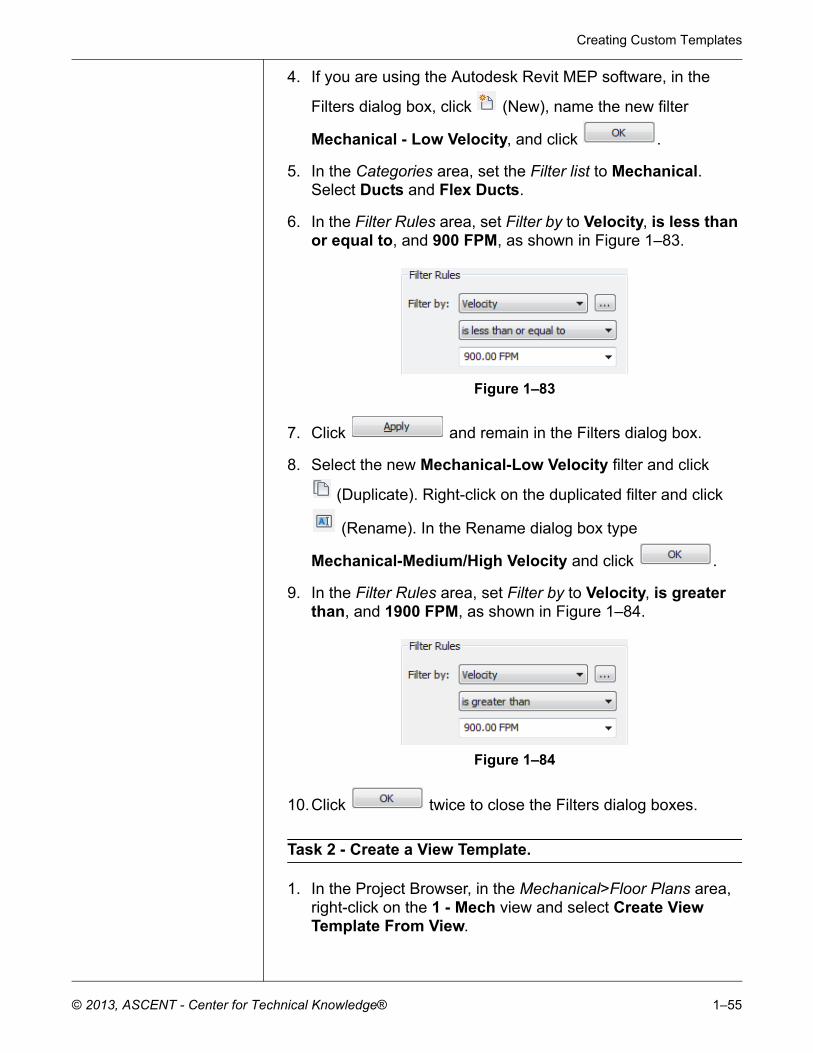
6. In the Filter Rules area, set Filter by to Velocity, is less than or equal to, and 900 FPM, as shown in Figure 1–83.
Figure 1–83
7. Click and remain in the Filters dialog box.
8. Select the new Mechanical-Low Velocity filter and click
(Duplicate). Right-click on the duplicated filter and click
(Rename). In the Rename dialog box type
Mechanical-Medium/High Velocity and click .
9. In the Filter Rules area, set Filter by to Velocity, is greater than, and 1900 FPM, as shown in Figure 1–84.
Figure 1–84
10.Click twice to close the Filters dialog boxes.
Task 2 - Create a View Template.
1. In the Project Browser, in the Mechanical>Floor Plans area, right-click on the 1 - Mech view and select Create View Template From View.
Autodesk Revit 2014 BIM Management: Template and Family Creation
1–56 © 2013, ASCENT - Center for Technical Knowledge®
2. Name the new view template Velocity Duct Plan and click
.
3. Next to V/G Override Filters, click The Visibility/Graphic Overrides dialog box opens with the Filter tab selected.
4. Click .
5. In the Add Filters dialog box, select the two filters you just
created and click .
6. For the Mechanical-Low Velocity filter, in the Projection/Surface>Lines column, select Override.
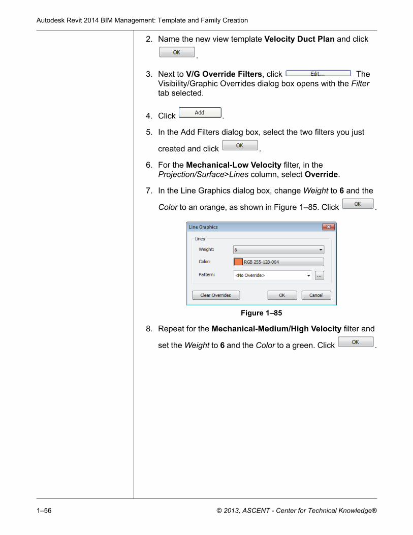
7. In the Line Graphics dialog box, change Weight to 6 and the
Color to an orange, as shown in Figure 1–85. Click .
Figure 1–85
8. Repeat for the Mechanical-Medium/High Velocity filter and
set the Weight to 6 and the Color to a green. Click .
Creating Custom Templates
© 2013, ASCENT - Center for Technical Knowledge® 1–57
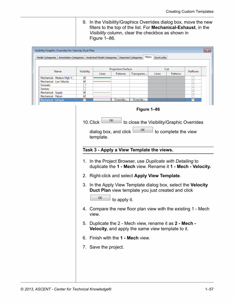
9. In the Visibility/Graphics Overrides dialog box, move the new filters to the top of the list. For Mechanical-Exhaust, in the Visibility column, clear the checkbox as shown in Figure 1–86.
Figure 1–86
10.Click to close the Visibility/Graphic Overrides
dialog box, and click to complete the view template.
Task 3 - Apply a View Template the views.
1. In the Project Browser, use Duplicate with Detailing to duplicate the 1 - Mech view. Rename it 1 - Mech - Velocity.
2. Right-click and select Apply View Template.
3. In the Apply View Template dialog box, select the Velocity Duct Plan view template you just created and click
to apply it.
4. Compare the new floor plan view with the existing 1 - Mech view.
5. Duplicate the 2 - Mech view, rename it as 2 - Mech - Velocity, and apply the same view template to it.
6. Finish with the 1 - Mech view.
7. Save the project.
Autodesk Revit 2014 BIM Management: Template and Family Creation
1–58 © 2013, ASCENT - Center for Technical Knowledge®
1.5 Settings for Mechanical and Electrical Projects
Autodesk Revit MEP only
In addition to the standard settings common to all Autodesk Revit projects, the Autodesk Revit MEP software also has specific Mechanical and Electrical settings that can be setup in a template or a project.
In the Autodesk Revit MEP software, the settings are found in
the Manage tab>Project Settings panel. Expand (MEP
Settings) and click (Mechanical Settings) or
(Electrical Settings).
Additional types of settings include Load Classifications, Demand Factors, and Building/Space Type Settings.
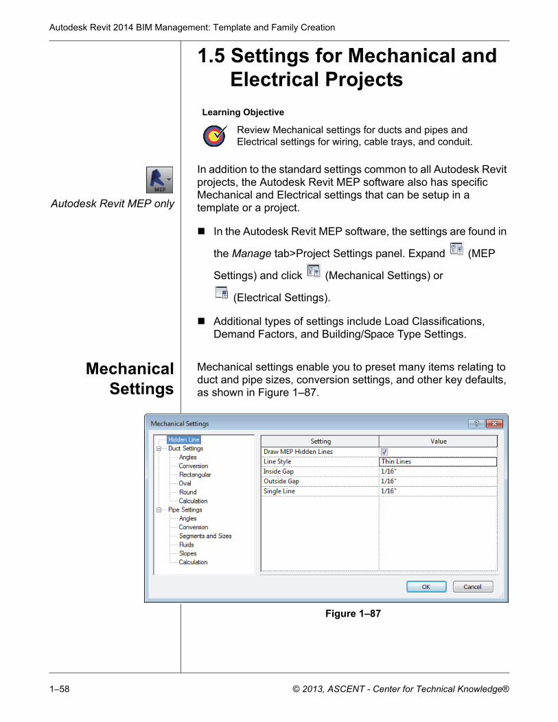
MechanicalSettings
Mechanical settings enable you to preset many items relating to duct and pipe sizes, conversion settings, and other key defaults, as shown in Figure 1–87.
Figure 1–87
Learning Objective
Review Mechanical settings for ducts and pipes and Electrical settings for wiring, cable trays, and conduit.
Creating Custom Templates
© 2013, ASCENT - Center for Technical Knowledge® 1–59
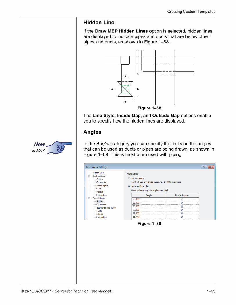
Hidden Line
If the Draw MEP Hidden Lines option is selected, hidden lines are displayed to indicate pipes and ducts that are below other pipes and ducts, as shown in Figure 1–88.
Figure 1–88
The Line Style, Inside Gap, and Outside Gap options enable you to specify how the hidden lines are displayed.
Angles
In the Angles category you can specify the limits on the angles that can be used as ducts or pipes are being drawn, as shown in Figure 1–89. This is most often used with piping.
Figure 1–89
Autodesk Revit 2014 BIM Management: Template and Family Creation
1–60 © 2013, ASCENT - Center for Technical Knowledge®
Duct Settings
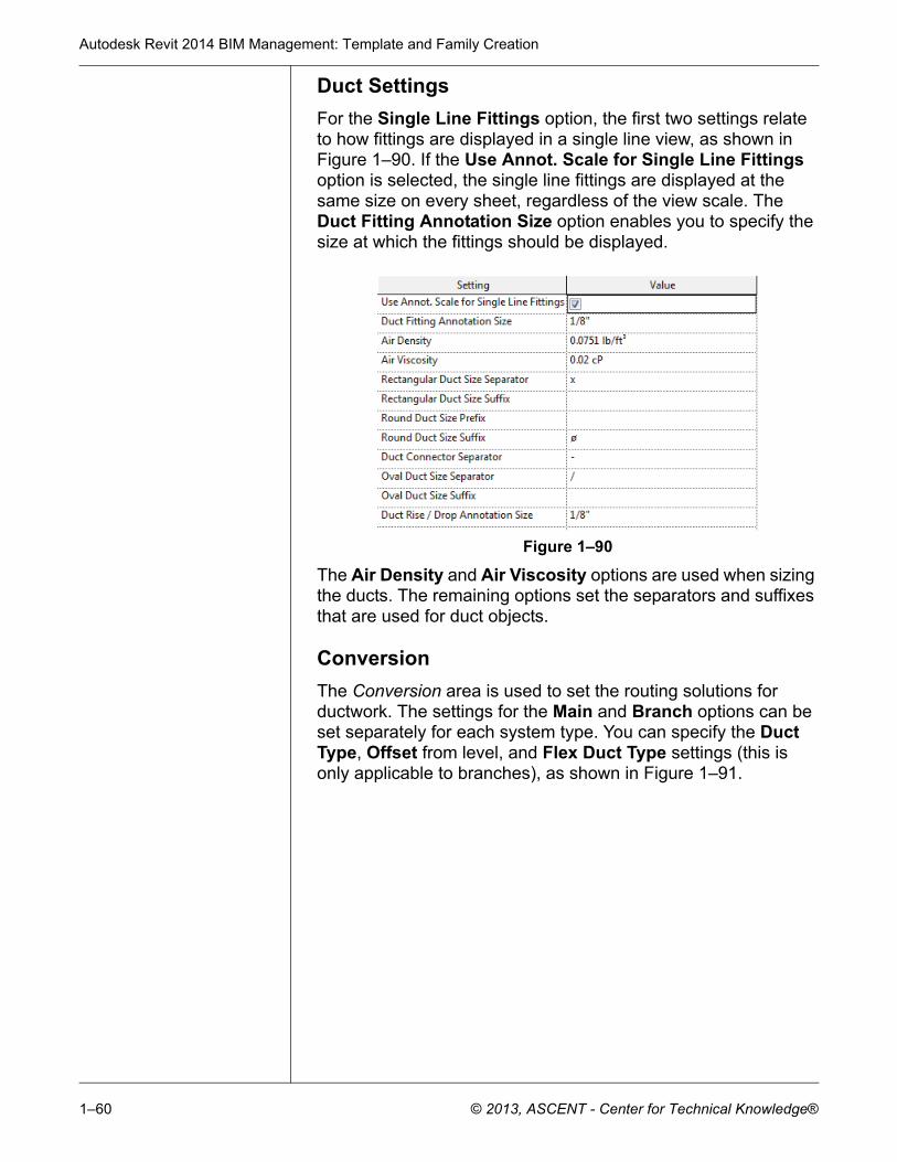
For the Single Line Fittings option, the first two settings relate to how fittings are displayed in a single line view, as shown in Figure 1–90. If the Use Annot. Scale for Single Line Fittings option is selected, the single line fittings are displayed at the same size on every sheet, regardless of the view scale. The Duct Fitting Annotation Size option enables you to specify the size at which the fittings should be displayed.
Figure 1–90
The Air Density and Air Viscosity options are used when sizing the ducts. The remaining options set the separators and suffixes that are used for duct objects.
Conversion
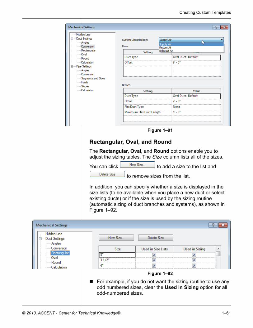
The Conversion area is used to set the routing solutions for ductwork. The settings for the Main and Branch options can be set separately for each system type. You can specify the Duct Type, Offset from level, and Flex Duct Type settings (this is only applicable to branches), as shown in Figure 1–91.
Creating Custom Templates
© 2013, ASCENT - Center for Technical Knowledge® 1–61
Figure 1–91
Rectangular, Oval, and Round
The Rectangular, Oval, and Round options enable you to adjust the sizing tables. The Size column lists all of the sizes.
You can click to add a size to the list and
to remove sizes from the list.
In addition, you can specify whether a size is displayed in the size lists (to be available when you place a new duct or select existing ducts) or if the size is used by the sizing routine (automatic sizing of duct branches and systems), as shown in Figure 1–92.
Figure 1–92
For example, if you do not want the sizing routine to use any odd numbered sizes, clear the Used in Sizing option for all odd-numbered sizes.
Autodesk Revit 2014 BIM Management: Template and Family Creation
1–62 © 2013, ASCENT - Center for Technical Knowledge®
Pipe Settings
Most of the options in the Pipe Settings area are identical to or similar to those in the Duct Settings area.
Pipe Segments and Sizes
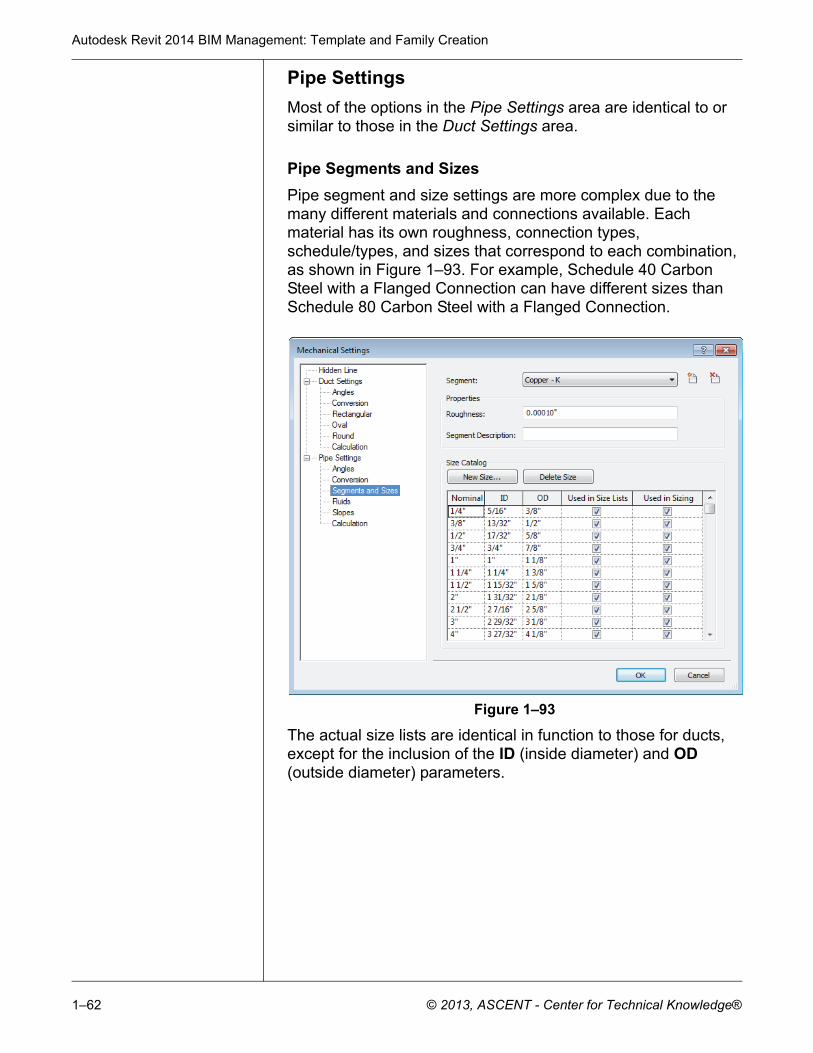
Pipe segment and size settings are more complex due to the many different materials and connections available. Each material has its own roughness, connection types, schedule/types, and sizes that correspond to each combination, as shown in Figure 1–93. For example, Schedule 40 Carbon Steel with a Flanged Connection can have different sizes than Schedule 80 Carbon Steel with a Flanged Connection.
Figure 1–93
The actual size lists are identical in function to those for ducts, except for the inclusion of the ID (inside diameter) and OD (outside diameter) parameters.
Creating Custom Templates
© 2013, ASCENT - Center for Technical Knowledge® 1–63
Click (Create New Pipe Segment) to open the New Segment dialog box (as shown in Figure 1–94), where you specify new Material, and/or Schedule/Type for the segment.
Figure 1–94
To delete a segment, click (Delete Pipe Segment).
Fluids
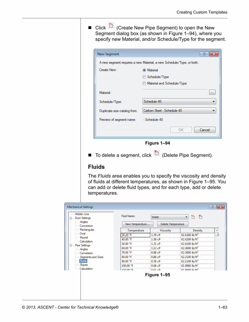
The Fluids area enables you to specify the viscosity and density of fluids at different temperatures, as shown in Figure 1–95. You can add or delete fluid types, and for each type, add or delete temperatures.
Figure 1–95
Autodesk Revit 2014 BIM Management: Template and Family Creation
1–64 © 2013, ASCENT - Center for Technical Knowledge®
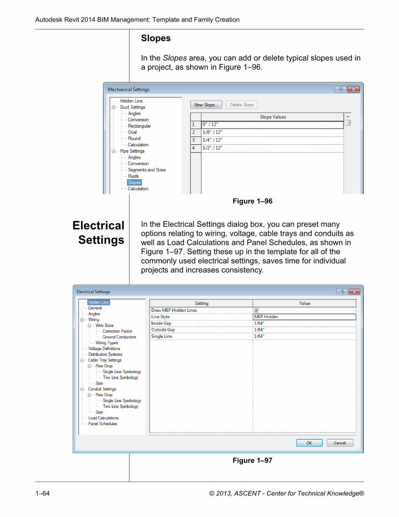
Slopes
In the Slopes area, you can add or delete typical slopes used in a project, as shown in Figure 1–96.
Figure 1–96
ElectricalSettings
In the Electrical Settings dialog box, you can preset many options relating to wiring, voltage, cable trays and conduits as well as Load Calculations and Panel Schedules, as shown in Figure 1–97. Setting these up in the template for all of the commonly used electrical settings, saves time for individual projects and increases consistency.
Figure 1–97
Creating Custom Templates
© 2013, ASCENT - Center for Technical Knowledge® 1–65
General
The parameters in the General area affect the display of electrical information. The Electrical Data Style option sets how the power information is displayed in the Electrical Data parameter in the Instance Properties of the electrical component. The Circuit Description option sets the formatting of the circuit description.
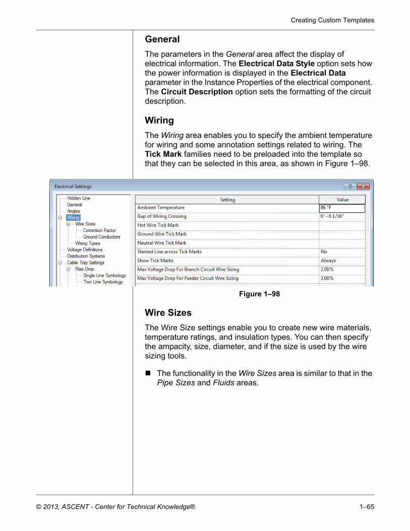
Wiring
The Wiring area enables you to specify the ambient temperature for wiring and some annotation settings related to wiring. The Tick Mark families need to be preloaded into the template so that they can be selected in this area, as shown in Figure 1–98.
Figure 1–98
Wire Sizes
The Wire Size settings enable you to create new wire materials, temperature ratings, and insulation types. You can then specify the ampacity, size, diameter, and if the size is used by the wire sizing tools.
The functionality in the Wire Sizes area is similar to that in the Pipe Sizes and Fluids areas.
Autodesk Revit 2014 BIM Management: Template and Family Creation
1–66 © 2013, ASCENT - Center for Technical Knowledge®
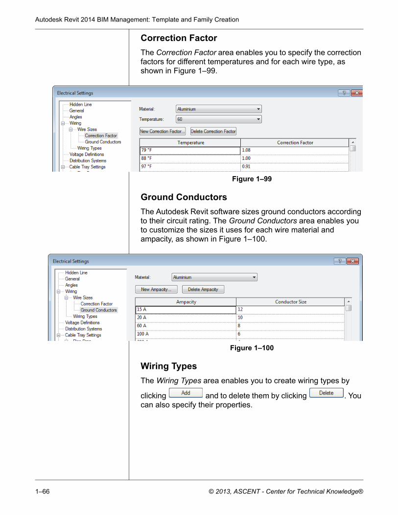
Correction Factor
The Correction Factor area enables you to specify the correction factors for different temperatures and for each wire type, as shown in Figure 1–99.
Figure 1–99
Ground Conductors
The Autodesk Revit software sizes ground conductors according to their circuit rating. The Ground Conductors area enables you to customize the sizes it uses for each wire material and ampacity, as shown in Figure 1–100.
Figure 1–100
Wiring Types
The Wiring Types area enables you to create wiring types by
clicking and to delete them by clicking . You can also specify their properties.
Creating Custom Templates
© 2013, ASCENT - Center for Technical Knowledge® 1–67
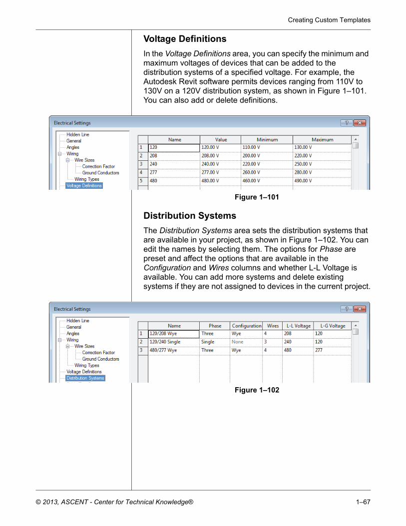
Voltage Definitions
In the Voltage Definitions area, you can specify the minimum and maximum voltages of devices that can be added to the distribution systems of a specified voltage. For example, the Autodesk Revit software permits devices ranging from 110V to 130V on a 120V distribution system, as shown in Figure 1–101. You can also add or delete definitions.
Figure 1–101
Distribution Systems
The Distribution Systems area sets the distribution systems that are available in your project, as shown in Figure 1–102. You can edit the names by selecting them. The options for Phase are preset and affect the options that are available in the Configuration and Wires columns and whether L-L Voltage is available. You can add more systems and delete existing systems if they are not assigned to devices in the current project.
Figure 1–102
Autodesk Revit 2014 BIM Management: Template and Family Creation
1–68 © 2013, ASCENT - Center for Technical Knowledge®
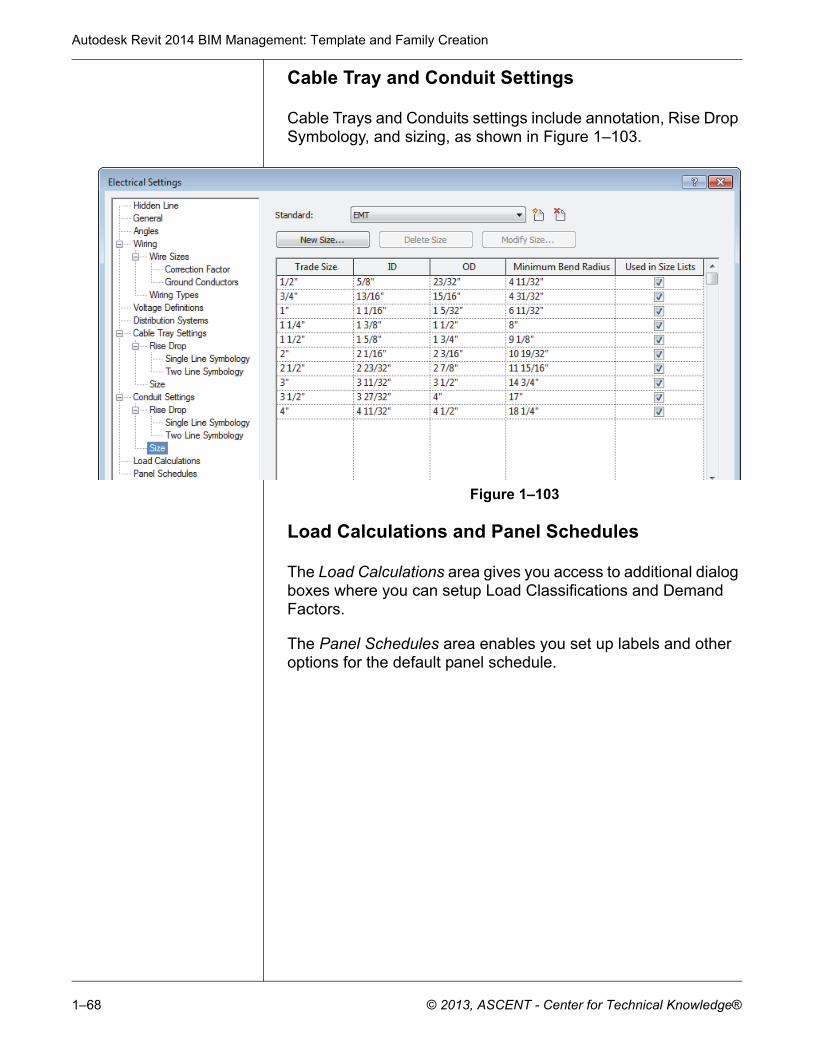
Cable Tray and Conduit Settings
Cable Trays and Conduits settings include annotation, Rise Drop Symbology, and sizing, as shown in Figure 1–103.
Figure 1–103
Load Calculations and Panel Schedules
The Load Calculations area gives you access to additional dialog boxes where you can setup Load Classifications and Demand Factors.
The Panel Schedules area enables you set up labels and other options for the default panel schedule.
Creating Custom Templates
© 2013, ASCENT - Center for Technical Knowledge® 1–69
1.6 Settings for Structural Projects
Autodesk Revit Structureonly
In addition to the standard settings common to all Autodesk Revit products, the Autodesk Revit Structure software has structural settings that need to be customized. To access them, click
(Structural Settings) in the Manage tab>Project Settings panel.
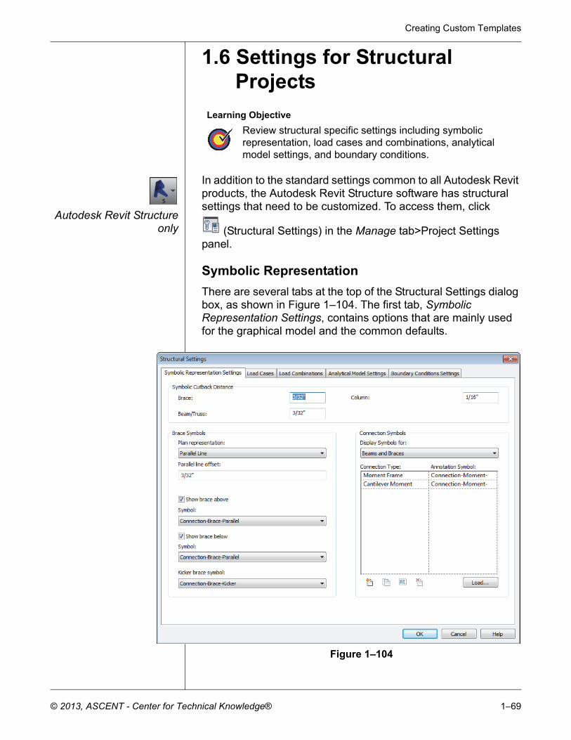
Symbolic Representation
There are several tabs at the top of the Structural Settings dialog box, as shown in Figure 1–104. The first tab, Symbolic Representation Settings, contains options that are mainly used for the graphical model and the common defaults.
Figure 1–104
Learning Objective
Review structural specific settings including symbolic representation, load cases and combinations, analytical model settings, and boundary conditions.
Autodesk Revit 2014 BIM Management: Template and Family Creation
1–70 © 2013, ASCENT - Center for Technical Knowledge®
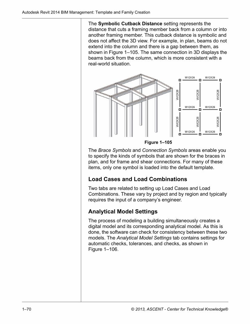
The Symbolic Cutback Distance setting represents the distance that cuts a framing member back from a column or into another framing member. This cutback distance is symbolic and does not affect the 3D view. For example, in plan, beams do not extend into the column and there is a gap between them, as shown in Figure 1–105. The same connection in 3D displays the beams back from the column, which is more consistent with a real-world situation.
Figure 1–105
The Brace Symbols and Connection Symbols areas enable you to specify the kinds of symbols that are shown for the braces in plan, and for frame and shear connections. For many of these items, only one symbol is loaded into the default template.
Load Cases and Load Combinations
Two tabs are related to setting up Load Cases and Load Combinations. These vary by project and by region and typically requires the input of a company’s engineer.
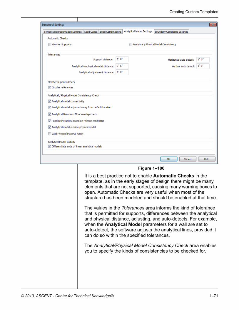
Analytical Model Settings
The process of modeling a building simultaneously creates a digital model and its corresponding analytical model. As this is done, the software can check for consistency between these two models. The Analytical Model Settings tab contains settings for automatic checks, tolerances, and checks, as shown in Figure 1–106.
Creating Custom Templates
© 2013, ASCENT - Center for Technical Knowledge® 1–71
Figure 1–106
It is a best practice not to enable Automatic Checks in the template, as in the early stages of design there might be many elements that are not supported, causing many warning boxes to open. Automatic Checks are very useful when most of the structure has been modeled and should be enabled at that time.
The values in the Tolerances area informs the kind of tolerance that is permitted for supports, differences between the analytical and physical distance, adjusting, and auto-detects. For example, when the Analytical Model parameters for a wall are set to auto-detect, the software adjusts the analytical lines, provided it can do so within the specified tolerances.
The Analytical/Physical Model Consistency Check area enables you to specify the kinds of consistencies to be checked for.
Autodesk Revit 2014 BIM Management: Template and Family Creation
1–72 © 2013, ASCENT - Center for Technical Knowledge®
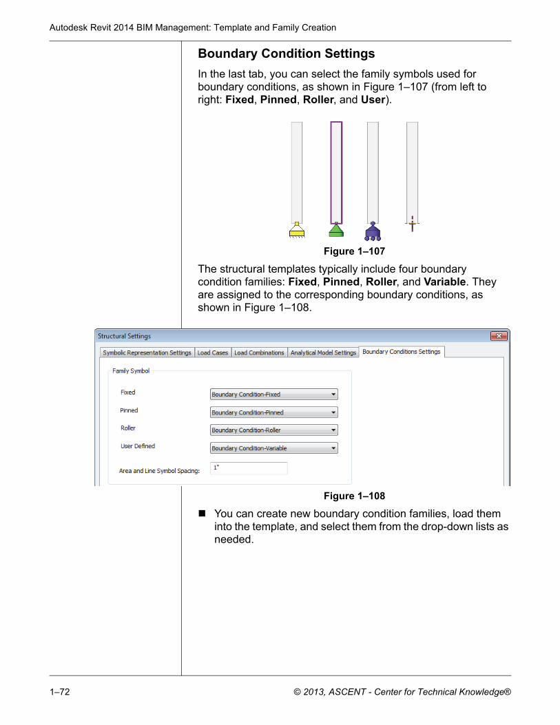
Boundary Condition Settings
In the last tab, you can select the family symbols used for boundary conditions, as shown in Figure 1–107 (from left to right: Fixed, Pinned, Roller, and User).
Figure 1–107
The structural templates typically include four boundary condition families: Fixed, Pinned, Roller, and Variable. They are assigned to the corresponding boundary conditions, as shown in Figure 1–108.
Figure 1–108
You can create new boundary condition families, load them into the template, and select them from the drop-down lists as needed.
Creating Custom Templates
© 2013, ASCENT - Center for Technical Knowledge® 1–73
Chapter Review Questions
1. Which of the following items are NOT setup in a template file?
a. Units
b. Annotation Types
c. Title blocks
d. Keyboard Shortcuts
2. What is a label?
a. A text type used in title blocks.
b. A dimension with text instead of numbers.
c. A type of text with variable information.
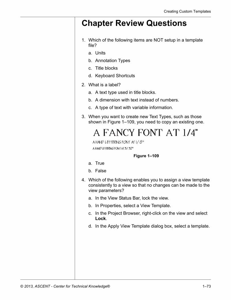
3. When you want to create new Text Types, such as those shown in Figure 1–109, you need to copy an existing one.
Figure 1–109
a. True
b. False
4. Which of the following enables you to assign a view template consistently to a view so that no changes can be made to the view parameters?
a. In the View Status Bar, lock the view.
b. In Properties, select a View Template.
c. In the Project Browser, right-click on the view and select Lock.
d. In the Apply View Template dialog box, select a template.
Autodesk Revit 2014 BIM Management: Template and Family Creation
1–74 © 2013, ASCENT - Center for Technical Knowledge®
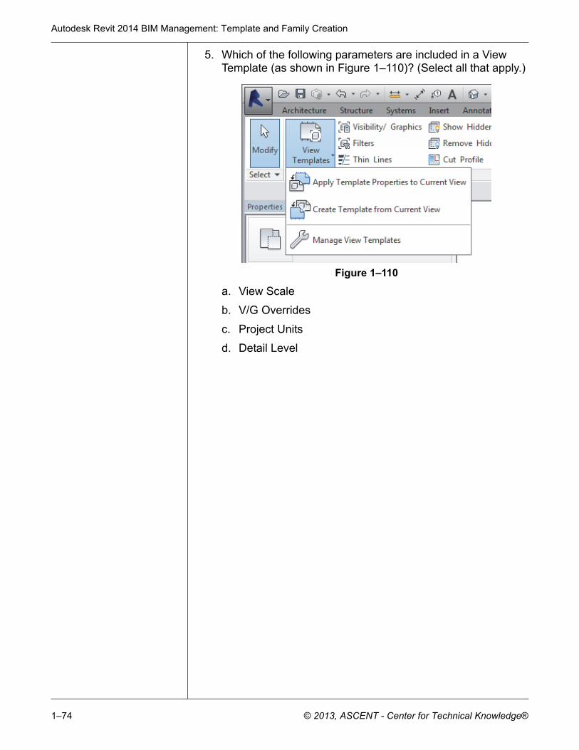
5. Which of the following parameters are included in a View Template (as shown in Figure 1–110)? (Select all that apply.)
Figure 1–110
a. View Scale
b. V/G Overrides
c. Project Units
d. Detail Level
Creating Custom Templates
© 2013, ASCENT - Center for Technical Knowledge® 1–75
Command Summary
Button Command Location
ApplyTemplate Properties to Current View
Ribbon: View tab>Graphics panel>expand View Templates
Project Browser: (right-click on a view) Apply Template Properties...
Arrowheads Ribbon: Manage tab>Settings panel>expand Additional Settings
Callout Tags Ribbon: Manage tab>Settings panel>expand Additional Settings
Create View Template From View
Ribbon: View tab>Graphics panel>expand View Templates
Project Browser: (right-click on a view)
Dimension Types Linear
Angular
Radial
Spot Elevation
Spot Coordinate
Spot Slope
Ribbon: Annotate tab>Dimensions panel>expand the panel title
Electrical Settings
Autodesk Revit MEP Ribbon: Manage tab>Settings panel
expand MEP Settings
Elevation Tags Ribbon: Manage tab>Settings panel>expand Additional Settings
Floor Plan Ribbon: View tab>Create panel> expand Plan Views
Keyboard Shortcuts
Ribbon: View tab>Windows panel> expand User Interface
Application Menu
Label Family Editor Ribbon: Create tab>Text panel
Loaded Tags Ribbon: Annotate tab>Tag panel>expand the panel title
Manage View Templates
Ribbon: View tab>Graphics panel>expand View Templates
Mechanical Settings
Autodesk Revit MEP Ribbon: Manage tab>Settings panel
expand MEP Settings
Autodesk Revit 2014 BIM Management: Template and Family Creation
1–76 © 2013, ASCENT - Center for Technical Knowledge®
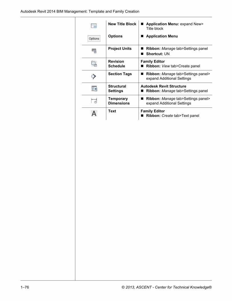
New Title Block Application Menu: expand New>Title block
Options Application Menu
Project Units Ribbon: Manage tab>Settings panel
Shortcut: UN
Revision Schedule
Family Editor Ribbon: View tab>Create panel
Section Tags Ribbon: Manage tab>Settings panel>expand Additional Settings
Structural Settings
Autodesk Revit Structure Ribbon: Manage tab>Settings panel
Temporary Dimensions
Ribbon: Manage tab>Settings panel>expand Additional Settings
Text Family Editor Ribbon: Create tab>Text panel