automated distillation tester model: ad-6 instruction … instruction 3.01.pdf · thank you for...
TRANSCRIPT

Automated Distillation Tester
Model: AD-6 Instruction Manual
Ver 3.01 100105
Read this manual thoroughly before using the product, and store in a safe place for future reference.
TANAKA SCIENTIFIC LTD, TOKYO, JAPAN

- 1 -
(Blank Page)

- 2 -
FOREWORD
Thank you for purchasing the Automated Distillation Tester Model AD-6 from Tanaka Scientific Limited. This instruction manual provides necessary information for using the AD-6. Read this manual thoroughly before use and ensure that you have understood its contents. This manual employs the following precautionary notation. For your safety, ensure that you understand these precautions and heed them at all times.
! WARNING: Warnings indicate a significant risk of death or serious physical injury if the information is ignored.
! CAUTION: Cautions indicate a significant risk of physical injury or property damage if the information is ignored.
USES
! WARNING: This product is only to be used for distillation measurements, as prescribed in ASTM D86 "Standard Test Method for Distillation of Petroleum Products at Atmospheric Pressure", ASTM D850 “Standard Test Method for Distillation of Industrial Aromatic Hydrocarbons and Related Materials” and ASTM D1078 “Standard Test Method for Distillation Range of Volatile Organic Liquids”.
This product automates the testing procedures prescribed in ASTM D 86, D850 and D1078 for making distillation measurements and is not to be used for any other purpose.

- 3 -
About This Manual
This manual is intended for all operators of the AD-6. The reader is assumed to have sufficient knowledge of ASTM procedures and standards as well as knowledge of the correct handling procedures for hazardous materials.
The content this manual is subject to change without notice due to enhancements to the performance and functionality of the tester.
If this manual is lost or damaged, contact Tanaka Scientific Limited or an authorized distributor for a replacement copy.
The contents of this manual have been thoroughly reviewed. If any pages are missing, out of order, or the manual contains spelling, grammatical or descriptive errors, please contact Tanaka Scientific Limited or an authorized distributor.
BEFORE USE Before using the product, ensure that you have read this manual thoroughly and have understood all of the content. If you have any questions, be sure to contact Tanaka Scientific Limited or an authorized distributor.
Keep this manual in a safe, easily accessible place.
This product is to be used for its intended purpose only.
Adhere strictly to all procedures given in this manual. Ensure that you understand
and abide by all (
! Warnings) and ( ! Cautions) given in this manual.

- 4 -
WARNINGS AND CAUTIONS FOR SAFE USE Failure to follow all of the warnings and cautions listed below may result in damage to the tester and/or serious personal injury. Tanaka Scientific Limited will not assume any responsibility for faults or accidents arising from failure to adhere to these instructions.
Installation Environment
! Warning: The tester must be installed in a well-ventilated environment. As samples release inflammable and/or toxic gases, inadequate ventilation may result in poisoning.
! Warning: Install the tester on a strong level table. Keep inflammable substances away from the tester. Ensure that a fire extinguisher is kept near the tester. If the table is unstable, the tester may fall down causing a fire.
Electric Connection
! Warning: Observe the following instructions when handling
power cables and electric connections:
· Do not connect or disconnect any cables or electrical connections when the mains power is ON.
· Do not handle any cables or electrical connections with wet hands.
· Never use the cord to pull a plug from an outlet. · Do not place heavy items on cords or cable. · Do not use force to bend any cords or cables. · Ensure that all electric connections (plugs,
sockets, connectors, etc.) are free of dust. · Keep all cables and electrical connections free of
water and other liquids.

- 5 -
Failure to adhere to the above precautions may result in electric shock, damage to the tester, cords and/or cables, and/or fire due to overheating.
! Warning: Ensure that supply voltage meets the specifications of the product. Do not turn the power on until all electric connections are secured. Incorrect power supply specifications or loose electric connections may damage the tester and result in electric shock and/or other electrical accidents.
! Warning: Ensure all ground wires are securely grounded. Loose or disconnected ground wires may result in electric shock. Never connect the ground wires to gas pipes. Doing so may result in a fire or explosion. Ground wires may be connected to one of the following: · Ground terminal of a power outlet · Copper bar buried 65cm or more underground · Water pipes as authorized by your local water
bureau as a grounding object
Handling Precautions
! Warning: Be sure to confirm test configuration prior to every test. Testing using incorrect parameters or with no boiling chips may cause a sample to bump and catch fire.
! Warning: Never touch the flask with bare hands after testing. The danger of burns exists, even after cooling.
! Warning: Never discard hot samples. If a hot sample is discarded into a container containing low flash point waste oil, a fire or explosion may result.

- 6 -
Operational Precautions
! Warning: Never touch the heater section with bare hands during operation. The cell is heated to high temperatures during operation and can cause serious burns.
! Warning: The tester is not to be operated unattended. Great danger exists if the tester falls or is knocked over. For safety reasons, an operator should always be in the same room as the running tester.
! Warning: If the tester makes any abnormal noises or exhibits any abnormal behavior, stop operation immediately, turn the power off at the mains, and contact Tanaka Scientific Limited or an authorized distributor.

- 7 -
Consumables, Accessories and Replacement Parts
! Caution: Use only Tanaka Scientific Limited genuine consumables, parts and accessories or such parts as recommended by Tanaka Scientific Limited.
Repairs, Alterations and Maintenance
! Warning: Do not make any modifications or alterations to the tester without the approval of Tanaka Scientific Limited.
! Warning: Do not attempt to repair the tester yourself. In the event that the tester exhibits any abnormal behavior whatsoever, contact Tanaka Scientific Limited or an authorized distributor.
! Warning: Only Tanaka Scientific Limited service personnel or authorized representatives are to repair or maintain the tester.

- 8 -
(Blank Page)

- 9 -
Contents FOREWORD..................................................................................................................................2 USES ………………………………………………………………………………………………………..2 About This Manual .........................................................................................................................3 BEFORE USE................................................................................................................................3 WARNINGS AND CAUTIONS FOR SAFE USE ............................................................................4 Contents.........................................................................................................................................9 1 Section Names and Functions ...........................................................................................11 2 Installation..........................................................................................................................14
2.1 Installation Site............................................................................................................14 2.2 Setting of Fire Containment Shutter ............................................................................14 2.3 Electrical Connections.................................................................................................14 2.4 Nitogen Gas Connection (for fire containment) ...........................................................15 2.5 Supplying Circulating Solution ....................................................................................16
3 Routine Daily Inspection ....................................................................................................17 4 Prior to Testing ..................................................................................................................18
4.1 Starting the Tester.......................................................................................................18 4.2 Drying the Condenser Tube ........................................................................................19 4.3 Setting a Sample.........................................................................................................19
5 Starting a Test ...................................................................................................................20 5.1 Starting a Test.............................................................................................................20 5.2 Test Sequence............................................................................................................21 5.3 Test without a 100% Sample in the Graduated Cylinder.............................................22
6 Terminating a Test .............................................................................................................23 6.1 Termination and Dry Point (D.P CUT).........................................................................23 6.2 Termination at a Set Distillation Percentage (% CUT) ................................................23 6.3 Termination at Set Temperature (°C CUT)..................................................................23 6.4 Termination after 5min from 95% recovery (Time, Cut) ..............................................23
7 Reprinting and Resending Data after Residue...................................................................24 7.1 Setting the Residue Again...........................................................................................24 7.2 Reprinting....................................................................................................................24 7.3 Resending...................................................................................................................24 7.4 Displaying and Printing Previous Distillation Data.......................................................25
8 Attaching the Temperature Sensor and Dry Point Sensor .................................................26 8.1 Attaching the Temperature Sensor .............................................................................26 8.2 Attachment Location of the Dry Point Sensor and Temperature Sensor for BTX........27
9 Setting Test Parameters ....................................................................................................28 9.1 Select Mode ................................................................................................................28 9.2 How to Set Test Parameters .......................................................................................29

- 10 -
9.3 Manual Heater Control ................................................................................................31 10 Maintenance ......................................................................................................................32
10.1 Inspecting and Replenishing Circulating Solution .......................................................32 10.2 Replacing Circulating Solution ....................................................................................33 10.3 Fire Containment Shutter ............................................................................................34 10.4 Error Status and Fault .................................................................................................34
11 Inspection and Post-sale Service.......................................................................................36 11.1 Periodic Maintenance..................................................................................................36 11.2 Consumables and Accessories...................................................................................36 11.3 Troubleshooting ..........................................................................................................37 11.4 Period of Warranty ......................................................................................................37 11.5 Period of Availability of Maintenance Tools.................................................................37
12 Post-delivery Notes............................................................................................................38 12.1 Long Periods of Dormancy..........................................................................................38 12.2 Lost Instruction Manuals .............................................................................................38 12.3 Transfer.......................................................................................................................38 12.4 Disposal ......................................................................................................................38
13 Specifications.....................................................................................................................39 Product Warranty .........................................................................................................................44

- 11 -
1 Section Names and Functions
Fig. 1 Model AD-6
(1) (2)
(3)
(4)
(5)
(6)
(11)
(10)
(7)
(8)
(12)
(16) (15)
(14) (13)
Top
Left Front Right
(17)
.
(18)(19)
(9)
(20)

- 12 -
(1) Temperature Sensor Connector: Connect the temperature sensor here.
(2) Dry Point Sensor Connector: Connect the dry point sensor (option) here.
(3) Fire Containment Shutter: Closes to prevent a fire if a flask breaks, a sample catches fire, or
the thermofuse blows. Do not close when starting a test, thermofuse blows.
(4) Circulating Water Verification Window: Allows the user to view the level and status of the
internal circulating solution.
(5) Heater Door: Open this door when inserting or removing a flask. Be sure to hold the knob
because the door becomes very hot.
(6) Heater Height Adjustment Dial: Raises or lowers the heater unit to set the flask in the correct
location.
(7) Printer (Option): Prints distillation data and plots a distillation curve.
(8) Fire Containment Nitrogen Inlet Port: Used to discharge nitrogen gas into the heater section
in case of fire. If the nitrogen line is connected, the solenoid valve opens automatically,
similarly to the fire containment shutter, if the thermofuse is blown. The nitrogen gas in
combination with the shutter helps to control fires and prevent the spread of flames.
The size of the inlet port is PT1/4 female, and recommended Nitrogen gas pressure is 500 kPa.
(9) Heater unit level adjuster: Can be adjusted to keep the unit level
(10) LCD display: Displays various configuration menus, distillation data, distillation curves and
error messages.
(11) Operating Panel: Contains START, COOL, RESET and other keys for operating the tester.
Tester settings for each mode can be changed using the keys on this panel.
(12) Temperature Sensor Holder: Insert the temperature sensor here during pre-cooling.
(13) Heater Status Lamp: Continuously lit during heating, flashing during temperature adjustment.
(14) Condensation Drain: Drains condensation pooled in the receiver compartment.
(15) Manual Fire Containment Shutter Activator: Press this button to test the fire depressant
shutter. This switch can also be used to manually close the shutter if the shutter fails to close
automatically during a fire.
(16) RS-232C Connector: Connect a personal computer with LIMS communication software and
Tanaka's ADManager (option) installed to this communications port.
(17) Circuit Breaker: Pops out and cuts power to the tester to protect the circuits if excess current
is detected. To reset, turn the main switch off once, rectify the cause of the current overload,
and press the circuit breaker button.
(18) Mains Power Switch: Turns the tester on and off.
(19) Power Cable Socket: Connect one end of the power cable to this socket and the other end to
an outlet meeting the specifications.
(20) Temperature Sensor Rest: Place the temperature sensor when stand-by.

- 13 -
Fig. 2 Model AD-6 Operator Panel
(1) DISP CHANGE Key: Press this key to toggle between the STANDBY and RUN screens.
(2) PRINT Key: Press this key to reprint test results, plot distillation curves, and to print
temperature correction values, test parameters, and other settings if optional printer is installed
(3) MANUAL CUT Key: Press this key to stop testing manually.
(4) FUNCTION Key: Press this key to change from the RUN screen to the Distillation Curve screen
while a test is running. Also, the menu can be displayed by pressing this key and the RESET
key at the same time.
(5) Up and Down Keys: Use these keys to select a test mode (long cursor) or to change an item
or increment or decrement a value at the cursor (short cursor).
(6) Left and Right Keys: Use these keys to move the cursor (short cursor). This is mainly used
when changing test parameters (on the STANDBY screen).
(7) Enter Key: Use this key accept the mode name and move the cursor to the test parameters to
allow them to be changed.
(8) RUN Lamp: Lights at the start of a test. (Red)
(9) COOL Lamp: Lights while the heater section is cooling after a test. (Green)
(10) START Key: Press this key to start a test.
(11) COOL Key: Press this key to cool the heating section as required. If this key is pressed during
testing, the test is terminated and the heater section cooled for 10 minutes.
(12) RESET Key: This key is mainly used to abort testing or cooling. Pressing this key returns the
tester to the standby state and displays the STANDBY screen shown in Fig.5 on Page 18.
(1) (2) (3) (4)
(5)
(5)
(6)
(7)
(8) (9)
(10) (11) (12)
(6)

- 14 -
2 Installation 2.1 Installation Site
! Warning: The tester must be installed in a well-ventilated environment.
! Warning: Install the tester on a strong level table.
Keep inflammable substances away from the tester. Ensure that a fire extinguisher is kept near the tester. If the table is unstable, the tester may fall down causing a fire.
Install the tester on a strong, level bench in a well-ventilated location.
Do not expose the tester to any of the following:
· High temperatures (> 30 °C)/ low temperatures (< 10 °C) or high humidity (> 90%)
· Direct sunlight
· Dust
· Rapid temperature changes
2.2 Setting of Fire Containment Shutter
Lift and fix the Fire Containment Shutter to the hook.
2.3 Electrical Connections
! Warning: Observe the following instructions when handling
power cables and electric connections:
· Do not connect or disconnect any cables or electrical connections when the mains power is ON.
· Do not handle any cables or electrical connections with wet hands.
· Never use the cord to pull a plug from an outlet. · Do not place heavy items on cords or cable. · Do not use force to bend any cords or cables. · Ensure that all electric connections (plugs, sockets,
connectors, etc.) are free of dust.

- 15 -
· Keep all cables and electrical connections free of water and other liquids.
Failure to adhere to the above precautions may result in electric shock, damage to the tester, cords and/or cables, and/or fire due to overheating.
! Warning: Ensure that supply voltage meets the specifications of the product.
! Warning: Ensure all ground wires are securely grounded. Loose or disconnected ground wires may result in electric shock. Never connect the ground wires to gas pipes. Doing so may result in a fire or explosion. Ground wires may be connected to one of the following: · Ground terminal of a power outlet · Copper bar buried 65cm or more underground · Water pipes as authorized by your local water
bureau as a grounding object
Connect the power cable to the right side of the tester when viewed from the front and the power
plug to an outlet meeting the tester specifications. (1) The maximum power consumption of this tester is 1.5 kW. When sharing an outlet with other
electrical appliances, make sure that the total power consumption does not exceed the outlet
capacity.
Note (1) The standard power cable comes with a three-prong plug. If the plug does not fit
your outlet, you will need to change the plug.
If the outlet does not have a ground terminal (as in ordinary home outlets), connect
the power cable through a ground adapter (triangular add-on). In this case, be sure
to ground the tester with an extension ground cord.
2.4 Nitogen Gas Connection (for fire containment)
Connect nitrogen gas piping to inlet port (see Fig. 1 (8)).
The size of the nitrogen gas inlet port is PT1/4 female. Connect PT1/4 male joint.
The recommended nitrogen gas pressure is 500 kPa.

- 16 -
2.5 Supplying Circulating Solution
Check the circulating solution is already filled or not. Some of AD-6s are shipped without filling
circulation solution to avoid freezing in transit. If the slotion is empty, pour in the solution to the
AD-6 as follows. The solution capacity is about 1.6 liters.
Recommended solution is as follows
Lowest ambient temperature < 5oC: Distilled water + Antifreez*
*: Cooling capacity will be decrease if Antifreez propotion will be over 10%.
Lowest ambient temperature > 5 oC: Distilled water
(1) Remove the circulating solution verification window from the left side of the tester (see Fig. 3). (2) Remove the cap of the circulating solution tank and pour the solution to MAX (see Fig. 4). (3) Replenish the solution to MAX again after lower the solution level. When the solution reaches a
water pump, surface descent will stop. (4) Turn ON the MAIN switch of the AD-6, solution surface will descent again. Replenish the
solution to MAX again. (5) Return the removed items to their original positions.
Fig.3 Check window
Solution check window
Remove this screw
Fig.4 Solution tank
Solution tank

- 17 -
3 Routine Daily Inspection
The following should be checked routinely before using the tester:
Table 1: Checklist
Item Description
Appearance
Electrical connections
(Before turning the
main power on…)
Operation of each
component
· The tester has no apparent damage.
· The power cable is not damaged.
· The power plug is fully inserted into the outlet.
· The grounding cable is properly connected (only applicable if using the ground adapter)
· The circulating solution is filled to the specified level.
< After turning the main power on…>
· The display appears to be functioning correctly
· The circulating solution is circulating normally.
· Each key functions normally when pressed.
· The condenser bath and receiver compartment are at the set temperatures.
· Fire containment shutter closes correctly by pressing Manual Fire Containment Shutter Activator. (See 10.3 on page 33)
! Warning: Do not attempt to repair the tester yourself. In the event that the tester exhibits any abnormal behavior whatsoever, contact Tanaka Scientific Limited or an authorized distributor.

- 18 -
4 Prior to Testing
! Warning: Do not use flasks having a deformed bottom, fine
scratches or cracks, as these may break and cause a fire during testing.
! Warning: To prevent a sample from accidentally catching alight, adhere to the following three precautions:
· Do not leave the laboratory unattended during testing.
· Ensure that a fire extinguisher is located nearby. · Do not place any inflammable substances near the
tester.
! Caution: The standard graduated cylinder contains a Viton
O-ring. Do not use acetone, methyl ethyl ketone, acetic ethyl, or any other solvent, as solvents may cause the ring to inflate and damage the graduated cylinder.
※Optional graduated cylinder with Perfluoroelastomer O-ring is available
! Caution: Use boiling chips (Small stones or small porous ceramics) to avoid irregular boiling.
4.1 Starting the Tester Turn on the main power switch. The test unit comes on and displays the screen shown in Fig. 5.
< STANDBY 1 > BAROMETER 1013 hPa 1 GASOLIN(300) INIT TEMP1 250.0oC 2 KEROSIN(300) INIT TEMP2 450.0oC 3 NAPHTHA(300) HEAT/FREEZ 95.0 %4 KEROSIN(400) FINAL H (AUTO) + 0.0 % 5 GAS-OIL(400) TEMP RANGE 300 6 RESIDUE 1.0 % 7 DIST.RATE 4.5 %8 SET BATH 0.5 oC9 SET REC 15.0 oC 10 11 START TEMP 25.0oC12 BATH TEMP 12.3 oC 13 REC TEMP 18.0 oC
(Mode Selection) (Mode Parameters)
Fig. 5 STANDBY Screen
(1) Use the ↑ and ↓ keys on the operating panel to move the cursor and select a mode (2).
- 19 -
Note (2) For information on setting mode parameters, refer to "9.2 Setting Test Parameters" on Page 29.
(2) Wait until the condenser bath and receiver compartment reach the specified temperatures.
Note: Bath temperature is maintaind at 4oC when STANDBY even if set bath temperature is 0
oC to avoid icing. Once start a test, bath temperature will be mainatned at set temperature.
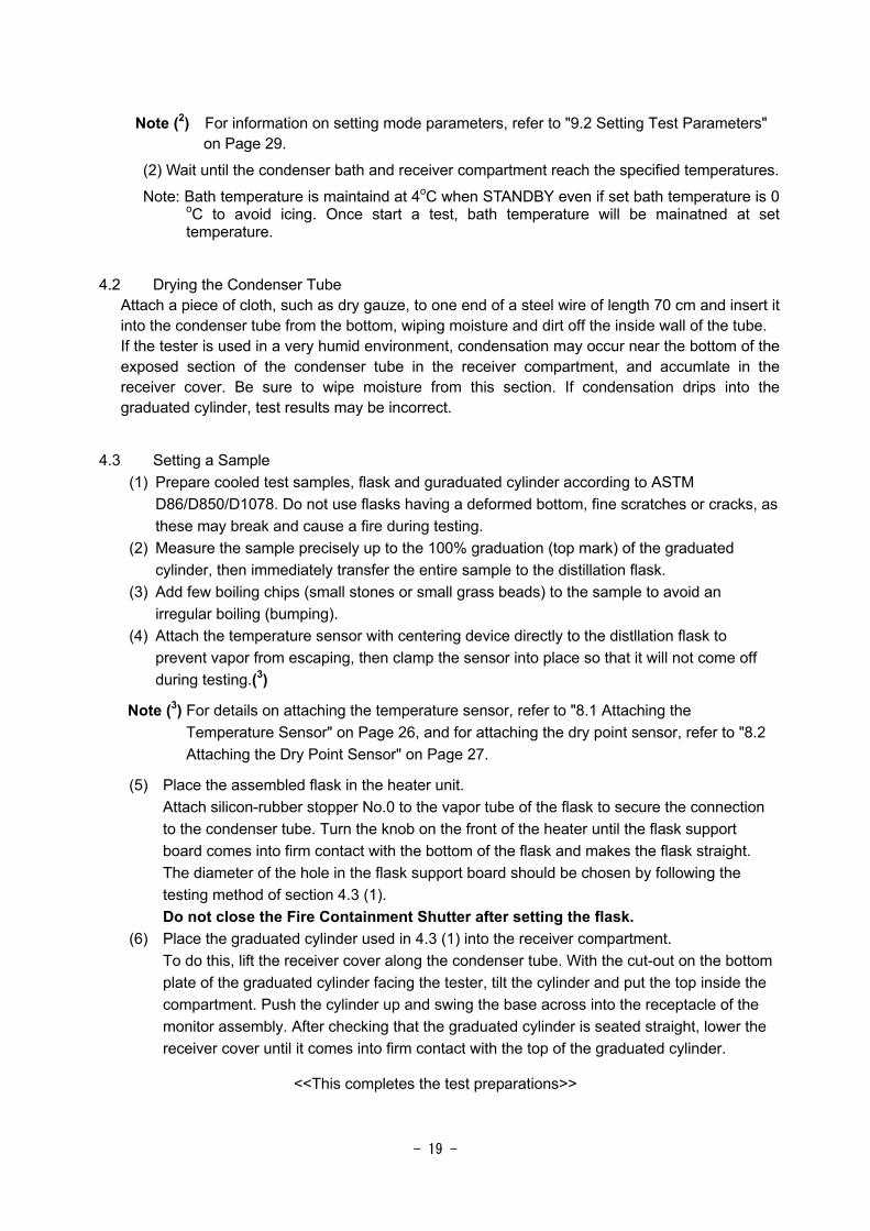
4.2 Drying the Condenser Tube Attach a piece of cloth, such as dry gauze, to one end of a steel wire of length 70 cm and insert it into the condenser tube from the bottom, wiping moisture and dirt off the inside wall of the tube. If the tester is used in a very humid environment, condensation may occur near the bottom of the exposed section of the condenser tube in the receiver compartment, and accumlate in the receiver cover. Be sure to wipe moisture from this section. If condensation drips into the graduated cylinder, test results may be incorrect.
4.3 Setting a Sample (1) Prepare cooled test samples, flask and guraduated cylinder according to ASTM
D86/D850/D1078. Do not use flasks having a deformed bottom, fine scratches or cracks, as these may break and cause a fire during testing.
(2) Measure the sample precisely up to the 100% graduation (top mark) of the graduated cylinder, then immediately transfer the entire sample to the distillation flask.
(3) Add few boiling chips (small stones or small grass beads) to the sample to avoid an irregular boiling (bumping).
(4) Attach the temperature sensor with centering device directly to the distllation flask to prevent vapor from escaping, then clamp the sensor into place so that it will not come off during testing.(3)
Note (3) For details on attaching the temperature sensor, refer to "8.1 Attaching the Temperature Sensor" on Page 26, and for attaching the dry point sensor, refer to "8.2 Attaching the Dry Point Sensor" on Page 27.
(5) Place the assembled flask in the heater unit. Attach silicon-rubber stopper No.0 to the vapor tube of the flask to secure the connection to the condenser tube. Turn the knob on the front of the heater until the flask support board comes into firm contact with the bottom of the flask and makes the flask straight. The diameter of the hole in the flask support board should be chosen by following the testing method of section 4.3 (1).
Do not close the Fire Containment Shutter after setting the flask. (6) Place the graduated cylinder used in 4.3 (1) into the receiver compartment.
To do this, lift the receiver cover along the condenser tube. With the cut-out on the bottom plate of the graduated cylinder facing the tester, tilt the cylinder and put the top inside the compartment. Push the cylinder up and swing the base across into the receptacle of the monitor assembly. After checking that the graduated cylinder is seated straight, lower the receiver cover until it comes into firm contact with the top of the graduated cylinder.
<<This completes the test preparations>>

- 20 -
5 Starting a Test 5.1 Starting a Test
Press the START key. (4) Note (4) The tester will not start if the starting conditions have not been satisfied, for example,
if the condenser bath is not within ±6 °C of the set temperature (see point (2) in
Section 10.4: Error Status and Faults on Page 34).
Do not start a test with shutter closed, thermofuse blows
(1) Adjust the photo levels of the initial boiling point sensor (IBP) and the fluid level follower
sensor (MS). During photo level adjustment, the following message is displayed:
<PHOTO ADJUSTMENT>
IBP OUT 80 IN 3800
MS OUT 80 IN 3800
(2) After photo level adjustment, the fluid level follower sensor begins to go down.
During the descent, the following message is displayed.
LEVEL FOLLOWER DESCENDING
(3) When the level follower sensor has detected the zero point of the graduated cylinder, the
RUNNING screen shown in Fig. 6 appears on the display and the RUN lamp lights. If the graduated cylinder is not in the receiver compartment, a problem occurs and the test is interrupted (see (1) in Section 10.4: Error Status and Faults on Page 34).
< RUNNING > IBP c s MODE(01) GASOLIN(300) 5 c s
10 c % DIST VOL 0.0 (%) 20 c % DIST TEMP 25.0 (oC) 30 c % DIST TIME 0 sec 40 c %
50 c % HEATER OUT 50 (V ) 60 c % BATH TEMP 1.0 (oC) 70 c % REC TEMP 15.0 (oC) 80 c % HEAT TEMP 25 (oC) 90 c %
95 c RE CORR 0.1(%) 97 c PREV.RESULT OFF E.P c s
Temperatur Dist time/rate
Fig. 6 RUNNING Screen (Testing)
If the FUNCTION key is pressed during testing, the Distillation Curve screen shown in Fig. 7 on Page 21 is displayed. Press the key once to view the distillation curve during testing and once again to return to the RUNNING screen shown in Fig. 6.

- 21 -
Dist Curve 80oC
IBP 35.0oC
E.P oC Vertical
oC/Div Horizontal
10%/Div 30 oC
Fig. 7 Distillation Curve Screen
<<From this point, testing proceeds automatically.>>
5.2 Test Sequence The first 4* minutes ·The heater block temperature is changed to the set
temperature IT1. ·TIME begins counting.
After 4* minutes ·The heater block temperature is changed to the set temperature IT2.
* The timing of IT1 is changeable. The defaoult value is “4 min”. IBP search begins ·The initial boiling point and the time until the point is found are
displayed at IBP. ·TIME is reset and counting resumes.
IBP search ends ·Automatic distillation control begin at a distillation rate of 4 to 5%/min when +0.5% is reached.
5% distillation volume ·The distillation temperature and the time from the initial boiling point until 5% are displayed at [5] on the display. ·TIME is reset and counting resumes.
10%, 20% distillation volume ·Distillation temperatures and rates are displayed at distillation volumes of 10 to 90%.
90% distillation volume ·TIME is reset for each and counting resumes. 95%, 97% dist. vol. ·Distillation temperatures are displayed at distillation volumes of
95 and 97%. Final heating starting pt. ·Automatic control stops, and heater output is controlled at FH.
·TIME is reset and counting resumes. End point (EP) detected ·The heater is turned off.
·The end point temperature and the time from the start to the end of final heating are displayed at EP.
5 minutes later ·Distillation data is printed by the built-in printer if optional printer is installed (refer to Fig. 18 on Page 4 3 for printout content) ·Distillation data is sent from the RS-232C port only when ADManager is OFF at Ext Out. For the data format, refer to the Maintenance Manual. ·The RUN lamp goes off. ·The COOL lamp lights and cooling starts (10-minute cooling).
10 min. after cooling begins ·The COOL lamp goes off and cooling stops.

- 22 -
·The STANDBY screen shown in Fig. 5 on Page 18 is displayed.
<< This completes testing. >>
5.3 Test without a 100% Sample in the Graduated Cylinder
(1) If the sample volume in the graduated cylinder is not 100%(5), place the graduated cylinder in the receiver compartment as is.
Note (5) Make sure that the sample volume is less than 100%. If the sample volume is not 100%, the ratio of the remaining oil needs to be changed. If the sample is 50 ml, for example, 1 ml of sample remaining in the flask must be calculated as 2%. Since this tester has a conversion formula, simply set the volume of oil (ml) and volume remaining in the flask (ml).
(2) Press the start button. After the performing operation of (1) from Seciton 5.1: Starting a Test on Page 20, the tester automatically detects the sample in the graduated cylinder. The level follower sensor stops with the following message displayed:
<SAMPLE MEASURING MODE>
SAMPLE DETECT, REMOVE CYLINDER!!
(3) Remove the graduated cylinder and transfer it to the flask (refer to "4.3 Setting a Sample" on Page 19). When the graduated cylinder has been removed, the level follower sensor starts descending again with the following message displayed:
<SAMPLE MEASURING MODE>
LEVEL FOLLOWER DESCENDING
(4) After transferring the sample to the flask, put the graduated cylinder in place once again. When the level follower has reached the lowermost point, the following message appears. Make sure that the graduated cylinder is in place, then press the START key again. The tester proceeds automatically, following the test sequence as described in Section 5.2 on Page 21.
<SAMPLE MEASURING MODE>
SET CYLINDER AND PRESS START SWITCH

- 23 -
6 Terminating a Test Under ordinary test conditions, tests end when the end point is detected (E.P CUT). However, tests can also be terminated arbitrarily under the following conditions:
6.1 Termination and Dry Point (D.P CUT)
A test can be terminated at the dry point in one of the following two ways:
(1) The dry point is detected by the dry point sensor (optional accessory) for automatic
termination. (2) The operator keeps an eye on the tester near the end of the test and presses the
MANUAL CUT key on the operator panel at the dry point.
6.2 Termination at a Set Distillation Percentage (% CUT)
Set the end point at %CUT in the test parameters to terminate the test. For the setting procedure, refer to (18) in Section 9.1: Selecting Mode on Page 28. This method is effective for distillation tests in a 10% distillation residue and carbon residue test. For the 10% distillation residue and carbon residue test, a 250 ml flask and a 200 ml (6) graduated cylinder are needed.
Note (6) The net capacity of the 200 ml graduated cylinder is 186±1 ml.
6.3 Termination at Set Temperature (°C CUT)
As in Section 6.2: Termination at Set Distillation Percentage, set the end point at °C CUT to terminate the test. For the setting procedure, refer to (17) in Section 9.1: Selecting Mode on Page 28. If % CUT is also set, the test terminates the first time either condition is satisfied.
6.4 Termination after 5min from 95% recovery (Time, Cut)
According to ASTM D1078, record the temperature after 5 min from 95% recovery and
terminate a test if dry point or end point cannot be detected. This function is valid only for
RANGE of “P200” and “P400”.

- 24 -
7 Reprinting and Resending Data after Residue After the residue is set again, corrected data can be reprinted and resent as follows:
7.1 Setting the Residue Again Set the residue on the RUN screen. If the STANDBY screen is displayed, press the DISPCHANGE key on the operator panel to change the display to the RUN screen (see Fig. 8). The residue can be set again by changing the value at RE CORR. To change the value, move the cursor with the ← or → key and increment or decrement the value with the ↑ or ↓ key.
7.2 Reprinting Corrected data can be reprinted or resent only when the RUN screen is displayed. Press the PRINT key to start printing. Press the FUNCTION key to display the Distillation Curve screen shown in Fig.9 and the PRINT key to start plotting a distillation curve.
7.3 Resending Press the MANUAL CUT key to start sending the data to the RS-232C port in the same format as at the end of a test (Note: This only applies when ADManager is OFF at Ext Out)
< TEST RESULT> IBP MODE(01) GASOLIN(300) 5 50.0c 70s
10 60.0c 4.5% DIST VOL 97.5 (%) 20 75.0c 4.5% DIST TEMP 25.0 (oC) 30 85.0c 4.5% DIST TIME 300 sec 40 95.0c 4.5%
50 110.0c 4.5% HEATER OUT 50 (V ) 60 120.0c 4.5% BATH TEMP 1.0 (oC) 70 130.0c 4.5% REC TEMP 15.0 (oC) 80 140.0c 4.5% HEAT TEMP 25 (oC) 90 150.0c 4.5%
95 170.0c RE CORR 0.1(%) 97 185.0c PREV.RESULT OFF E.P 205.0c 250s
Fig.8 RUN Screen (After Test)

- 25 -
Dist Curve 230oC
IBP 35.0oC
E.P 205.0oC Vertical
20oC/Div Horizontal
10%/Div 30 oC
Fig. 9 Distillation Curve Screen (After Test)
7.4 Displaying and Printing Previous Distillation Data
This tester stores previous distillation data.
When displaying previous distillation data, set PREV.RESULT on the RUN screen (after test), as shown in Fig.8 on Page 24, to ON and press the ENTER key.
TEST RESULT changes to PREVIOUS RESULT, and the previous distillation data is displayed. The data can be printed by pressing the PRINT key. The Distillation Curve screen (after test) allows the previous distillation curve to be displayed and printed.
When displaying the present test result, set PREV.RESULT on the RUN screen (after test), as shown in Fig.8 on Page 24, to OFF and press the ENTER key.
To change a setting to ON or OFF, move the cursor using the ← or → key and toggle the setting between ON and OFF using the ↑ or ↓ keys.

- 26 -
8 Attaching the Temperature Sensor and Dry Point Sensor 8.1 Attaching the Temperature Sensor
Attach the temperature sensor straight so that it will come to the center of the neck of the flask. The attaching position differs between the temperature sensor for fuel oil and that for BTX. Figures 10 and 11 show the corresponding positions.
Fig. 10 Attachment Location of the Temperature Sensor for Fuel Oil
Temp. Sensor
Centering Device
Horizontal
Flask
Vapor Tube
The upper end of Covar Chip (black metal) position to the bottom of inner wall of the root vapor tube.
Neck
O-ring

- 27 -
8.2 Attachment Location of the Dry Point Sensor and Temperature Sensor for BTX When attaching the dry point sensor, insert the temperature sensor into the Centering Device provided with the dry point sensor, and attach to the distllation flask as shown in Fig.11.
Fig. 11 Attachment Location of the Dry Point Sensor and Temp. Sensor for BTX
Temperature Sensor for BTX
Vapor Tube
End of the dry point sensor contacting the flask bottom
20 mm
Dry Point Sensor
Horizontal
Centering Device

- 28 -
9 Setting Test Parameters 9.1 Select Mode
To simplify the test parameters modification procedure, test parameters can be preset. The user can select a set of base settings by selecting a single mode number. The tester provides modes 1 to 13 on STANDBY 1 screen and 14 to 26 on STANDBY 2 screen (refer to Section 9.2: How to Set Test Parameters on Page 29). Each mode allows the following parameters to be set: (1) Initial Heating 1 : Initial heating temperature setting 1 (0 to 999.9°C) (2) Initial Heating 2 : Initial heating temperature setting 2 (0 to 999.9°C) (3) Final Heating Starting Point : Percentage of distillate for final heating (80 to 95%)
Set to 91.5% for group 1 and 2 samples and 93.5% for group 3 and 4 samples.
(4) Final Heating : Final heating voltage [(AUTO) ± 98% or (MANU) 0 to 98 V] Usually set to (AUTO)+00%.
(5) Temperature Range : 300 (0 to 300 °C to cover ASTM 7C thermometer) 400 (0 to 400 °C to cover ASTM 8C thermometer) P200 (0 to 200 °C for BTX and solvents) P400 (0 to 400 °C for solvents)
(6) Residue : Expected residue (0 to 9.9%) (7) Distillation Rate Setting: Control distillation rate (2.0 to 9.0 ml/min)
Usually set 4.5 ml/min. (8) Condenser Bath Setting : Condenser bath control temperature (0 to 69.9 °C) (9) Receiver Compartment Temperature : Receiver compartment control temperature (0 to
69.9 °C)
The above test parameters are displayed on the STANDBY screen. In addition, the following test parameters are provided as options (refer to Section 9.2: How to Set Test Parameters on Page 29):
(10) Loss Calculation Method : Choice of a method for calculating a loss
(graphical [GRAPH] or arithmetical [ARITH]) (11) Distillation Temperature Accuracy : Distillation temperature rounding (0.1 or 0.5 °C) (12) Distillation Volume Accuracy : Distillation volume rounding (0.1% or 0.5%) (13) Manual Heater Control : Manual heater control (ON or OFF)
(14) Both EP and DP Measurement : Measurement of end point and dry point (ON or OFF) (15) Hesitation Point Correction : Linear correction of hesitation points (ON or OFF) (16) Data Printout : Test result printing (ON or OFF)
Set OFF not to print test results by the printer of this device. (17) Distillation Temperature Cutoff : Test end at a set distillation temperature (0.1 to 399.9°C) (18) Distillation Volume Cutoff : Test end at a set distillation volume (0.1 to 99.9%) (19) IT&Rate Auto Setting : Automatic setting of the initial temperature for a sample of
unknown boiling point and distillation rate at 5% to 10% (OFF, INIT or RATE). When testing a sample of an unknown boiling point, select “INIT”. After the first running, AD-6 calculates appropriate IT1 and IT2 temperature, and then records them to the mode. This tester sets the initial temperature and enters the temperature automatically into IT1 and IT2 after the test. After the test, return the setting to OFF automatically. After settlement of IT1 and IT2, change this setting to “RATE” and then run the same sample again. After the running, AD-6 calculates appropriate heater output so that distillation rate around 5 to 10% will be fit for the test condition. The distillation rate around

- 29 -
5 to 10% and proportional control amount can be set not only by this method, but also by manually. For the detail, refer maintenance manual chapter 2.1.6.
(20) Baro Method : Choice of a method for barometric pressure correction. (ASTM D86, D850 or D1078) The default setting is D86. When D850 is selected, “Const A XXX” and “Const B XX” are displayed on the upper right of the screen. Enter 3 digit significant value to Const A, and 2 digit significant value to Const B before a test. (e.g. The constants of Toluene are A:0.0463 and B:0.000027. So, enter 463 to Const A and 27 to Const B) When D1078 is selected, “Const K XX” is displayed on the upper right of the screen. Enter 2 digit significant value to Const K before a test. (e.g. The constant of Toluene is 0.035. So, enter 35 to Const K)
(21) (ºC) → (%) Printing : Printing the distillation volume for a specific distillation temperature (8 points maximum)
(22) (%) → (ºC) Printing : Printing the distillation temperature for a specific distillation volume (8 points maximum)
9.2 How to Set Test Parameters
On the STANDBY and Test Parameters screens, the cursor may be one character long
(referred to as the short cursor) or longer (referred to as the long cursor).
The long cursor appears when the power is turned on, the RESET key is pressed, or the
display changes.
The long cursor can be moved up or down to the parameter to change using the ↑ and ↓
keys.
Press either the ← or → key to change the long cursor to the short cursor.
With the short cursor displayed, the cursor can be moved to the right or left using the ← and
→ keys, and data or numeric values changed using the ↑ and ↓ keys(7). When the short cursor is being displayed, press the ENTER key to return to the long cursor.
Note (7) After changing or setting data or numeric values, press the PRINT key to obtain a
hardcopy of the parameters changes or record parameters to some paper if . Save the
hard copy for re-entering parameters when the memory backup battery is replaced.
(1) Selecting a mode number Press the ↑ or ↓ key on the control panel to move the long cursor(8) from (Mode selection) on the STANBY screen shown in Fig. 5 on Page 18.
Note (8) If the ← or → key is pressed by mistake during mode number selection (short cursor displayed), press the ENTER key to revert to the long cursor.
(a) Switching from <Standby 1> to <Standby 2> Press the ↑ key when the long cursor is displayed in Mode 1 or the ↓ key in Mode 14.
(b) Switching from <Standby 2> to <Standby 1> Press the ↑ key when the long cursor is displayed in Mode 15 or the ↓ key in Mode 27.
(2) Setting or changing the parameters for a mode (a) Press the ENTER key on the STANDBY screen shown in Fig. 5 on Page 18 to move the
cursor to (Mode contents). (b) Set or change data using the ←, →, ↑ and ↓ keys. (c) After setting or changing data, return to the long cursor and press the ENTER key once
more. The cursor returns to (Mode selection).
- 30 -
(3) Setting the barometric pressure The barometric pressure only needs to be set once, not for each test (9)
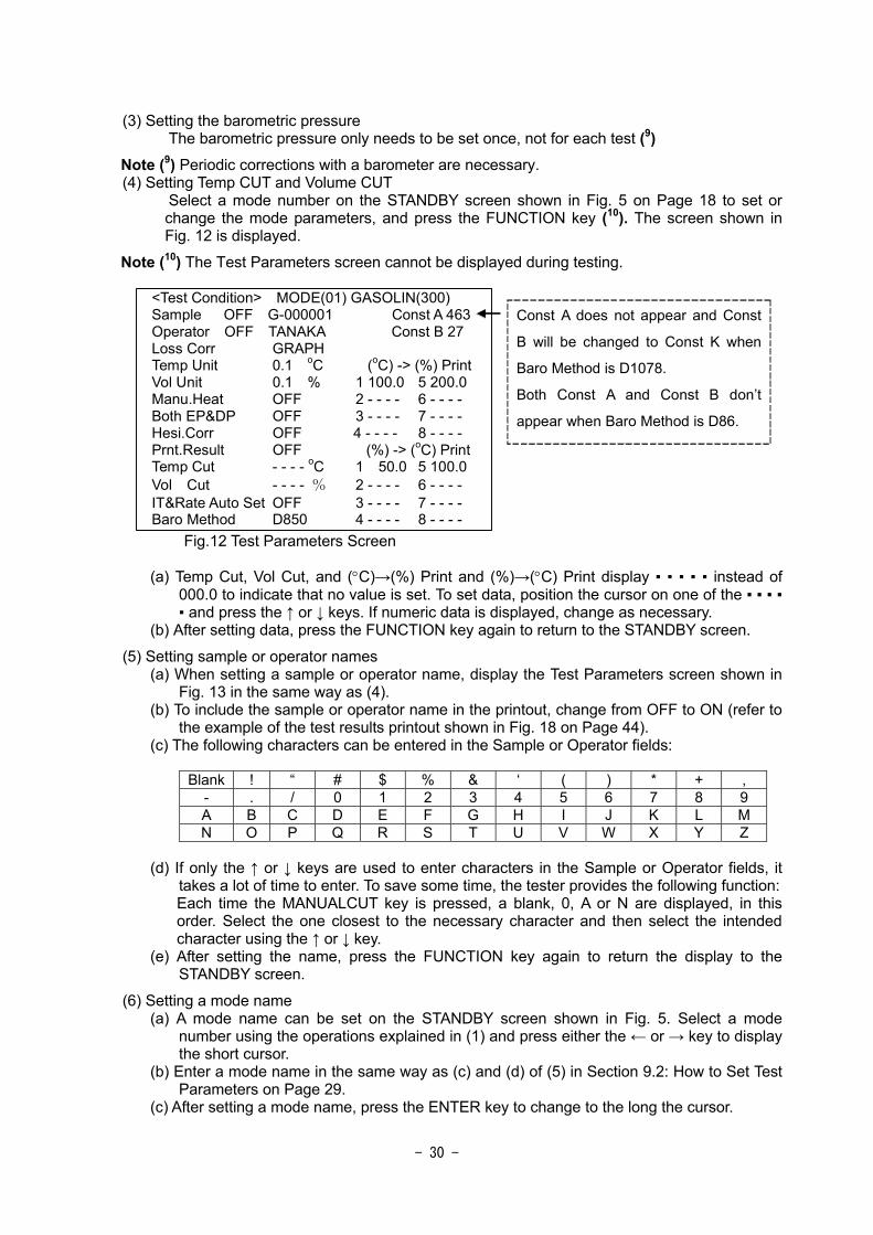
Note (9) Periodic corrections with a barometer are necessary. (4) Setting Temp CUT and Volume CUT Select a mode number on the STANDBY screen shown in Fig. 5 on Page 18 to set or
change the mode parameters, and press the FUNCTION key (10). The screen shown in Fig. 12 is displayed.
Note (10) The Test Parameters screen cannot be displayed during testing.
<Test Condition> MODE(01) GASOLIN(300) Sample OFF G-000001 Const A 463 Operator OFF TANAKA Const B 27 Loss Corr GRAPH Temp Unit 0.1 oC (oC) -> (%) Print Vol Unit 0.1 % 1 100.0 5 200.0 Manu.Heat OFF 2 - - - - 6 - - - - Both EP&DP OFF 3 - - - - 7 - - - - Hesi.Corr OFF 4 - - - - 8 - - - - Prnt.Result OFF (%) -> (oC) Print Temp Cut - - - - oC 1 50.0 5 100.0 Vol Cut - - - - % 2 - - - - 6 - - - - IT&Rate Auto Set OFF 3 - - - - 7 - - - - Baro Method D850 4 - - - - 8 - - - -
Const A does not appear and Const
B will be changed to Const K when
Baro Method is D1078.
Both Const A and Const B don’t
appear when Baro Method is D86.
Fig.12 Test Parameters Screen
(a) Temp Cut, Vol Cut, and (°C)→(%) Print and (%)→(°C) Print display instead of
000.0 to indicate that no value is set. To set data, position the cursor on one of the and press the ↑ or ↓ keys. If numeric data is displayed, change as necessary.
(b) After setting data, press the FUNCTION key again to return to the STANDBY screen.
(5) Setting sample or operator names (a) When setting a sample or operator name, display the Test Parameters screen shown in
Fig. 13 in the same way as (4). (b) To include the sample or operator name in the printout, change from OFF to ON (refer to
the example of the test results printout shown in Fig. 18 on Page 44). (c) The following characters can be entered in the Sample or Operator fields:
Blank ! “ # $ % & ‘ ( ) * + ,
- . / 0 1 2 3 4 5 6 7 8 9 A B C D E F G H I J K L M N O P Q R S T U V W X Y Z
(d) If only the ↑ or ↓ keys are used to enter characters in the Sample or Operator fields, it
takes a lot of time to enter. To save some time, the tester provides the following function: Each time the MANUALCUT key is pressed, a blank, 0, A or N are displayed, in this order. Select the one closest to the necessary character and then select the intended character using the ↑ or ↓ key.
(e) After setting the name, press the FUNCTION key again to return the display to the STANDBY screen.
(6) Setting a mode name (a) A mode name can be set on the STANDBY screen shown in Fig. 5. Select a mode
number using the operations explained in (1) and press either the ← or → key to display the short cursor.
(b) Enter a mode name in the same way as (c) and (d) of (5) in Section 9.2: How to Set Test Parameters on Page 29.
(c) After setting a mode name, press the ENTER key to change to the long the cursor.

- 31 -
(d) When entering several mode names, repeat steps (a) to (c).
9.3 Manual Heater Control The following screen appears when a test is started with Manual heater control “ON”.
<MANUAL HEAT > IBP 35.0c 350s MODE(01) GASOLIN(300) 5 50.0c 70s
10 60.0c 4.5% DIST VOL 97.5 (%) 20 75.0c 4.5% DIST TEMP 25.0 (oC) 30 85.0c 4.5% DIST TIME 300 sec 40 95.0c 4.5%
50 110.0c 4.5% HEATER OUT 50 (V ) 60 120.0c 4.5% BATH TEMP 1.0 (oC) 70 130.0c 4.5% REC TEMP 15.0 (oC) 80 140.0c 4.5% HEAT TEMP 25 (oC) 90 150.0c 4.5%
95 170.0c RE CORR 0.1(%) 97 185.0c PREV.RESULT OFF E.P 205.0c 250s
Fig.13 Manual Heater Control Run Screen
The test starts with 50% heater output. Operator can adjust heater output value by pressing Up-Down keys. Operator can change heater control method (Manual/Auto) by pressing START key during a test. For example, operator wants to control heater output from 80 to 90% recovery, push START key after starting a test, and then push START key again when recovery reaches to 80%, and then control heater output manually. Push START key again when recovery reaches to 90%, the AD-6 starts to control heater output automatically until test end. (Manual/Auto switching by START does not affect the setting of “Manu.Heat ON/OFF in the Test Condition screen.)

- 32 -
10 Maintenance
10.1 Inspecting and Replenishing Circulating Solution
Before using this tester, check the circulating solution. If the solution level is low, replenish the
solution as explained below.
The tester will be damaged if used without adequate circulating solution. In cold areas, use
antifreeze. If the circulating solution freezes, the tester will be damaged.
(1) Remove the circulating solution verification window from the left side of the tester (see Fig. 14). (2) Remove the cap of the circulating solution tank and replenish the solution to MAX (see Fig. 15). (3) Return the removed items to their original positions.
Solution tank
Solution check window
Remove this screw
Fig.14 Check window
Fig.15 Solution tank

- 33 -
10.2 Replacing Circulating Solution
! Caution: Before maintenance, be sure to turn the power off and remove the power plug from the outlet.
Before using the tester, be sure to check the circulating solution. If the solution is dirty,
replace it as explained below. Even if the solution is not dirty, replace it at least once every
two years. In cold areas, use antifreeze. If the circulating solution freezes, the tester will be
damaged.
(1) Remove the cover from the left side of the tester (see Fig. 16). (2) Remove the circulating solution tank stay and take out the circulating solution tank. (3) Remove the cap from the ciculating solution tank and tilt the tank to drain the circulating
solution (see Fig. 17). (4) After draining the solution, secure the circulating solution tank as it was and pour in the
solution in the same manner to 2.3 Supplying Circulating Solution on page 15.
Solution tank stay
Solution
Fig.16 Without the left side cover
Fig.17 Draining

- 34 -
10.3 Fire Containment Shutter
Press the manual shutter switch once ((15) in Fig. 1 on Page 11) to confirm operation as if
the thermofuse has been blown.
After confirming normal operation, press the switch again, lift the shutter and secure using
the shutter hook.
10.4 Error Status and Fault
If an error occurs in the last test, or an operational error or equipment fault occurs, details
are displayed and printed, the buzzer sounds for 10 seconds, and tests are interrupted and
prevented from starting. Check the cause of the error and contact one of the authorized
Tanaka distributors listed at the end of this manual.
If problems occur during testing, data indicating the cause of the problem is printed. Press
the RESET key to return to the STANDBY screen.
Example of Error Display
TROUBLE
NO RECEIVER ! ! <- Trouble description
REC 0.0 % DIST 25.0 oC
ROOM 25.0 oC BATH 1.0 oC
HEAT 25.0 oC D.P 0.0
Example of Error Print
TROUBLE DATE 2 / 8 / 20 11 : 30 : 00 NO RECEIVER ! ! <-Trouble contents VOL 0.0% DIST 25.0°C REC 25.0°C BATH 1.0°C HEAT 25.0°C D.P 0.0

- 35 -
Error messages indicating bad test parameters or operational errors
(1) [NO RECEIVER!!] No graduated cylinder is set before the start of the test.
(2) [BATH TEMP?]
The condenser block is not at the set temperature ± 6 °C at the start of a test.
(3) [M.S FLWR POSITION] A test has started when the level follower sensor is not at the upper fixed position.
(4) [HF POINT?]
The final heating start point is not set correctly. The setting range is from 80% to 95%. If started with a point outside this range, an error is generated.
(5) [THERMOFUSE]
The sample caught fire and the thermofuse was blown. If the thermofuse is blown, the fire buzzer sounds and the shutter closes. If the nitrogen pipe is connected to the fire containment nitrogen port ((8) in Fig.1: Model AD-6 on Page 11), the solenoid valve opens automatically to discharge nitrogen into the heater block to help controllig the fire. If a test is excuted with shutter closed, stove section will be heated abnormally, and then thermofuse will be blown. The fire containment shutter must be lifted/fixed to the shutter hook during a test.
The above errors are attributable to bad settings or operation. Eliminate the causes of any errors and repeat the test.

- 36 -
11 Inspection and Post-sale Service
11.1 Periodic Maintenance
This tester is fully inspected and calibrated prior to shipping, and should require no
readjustment immediately upon delivery.
To ensure high performance and maximum safety, however, the tester needs to be
maintained and adjusted periodically. For the detail, refer Maintenance Manual.
11.2 Consumables and Accessories
! Caution: Use only Tanaka Scientific Limited genuine consumables, parts and accessories or such parts as recommended by Tanaka Scientific Limited.
For an order or inquiry about consumables, accessories, or other replacement parts for this
tester, contact the authorized Tanaka distributor given in the warranty at the end of this
manual.
When placing an order, be sure to quote the product model "AD-6".
The most commonly used consumables and accessories are listed in Table 2: and
Accessories for Model AD-6.
Table 2: Consumables and Accessories for Model AD-6
Graduated cylinder assemblies: 100 ml・200 ml (net: 186 ml)
Distllation flasks: 100 ml 125 ml 200 250ml
Flask support boards: Ø25, Ø32, Ø38, Ø50, Ø70 hole
Roll paper (thermal paper for built-in printer)
Temperature sensors: For fuel oil for BTX
Thermofuse: 5 pcs/Pack
Temperature Sensor Centering Device for 125 ml flask
Dry Point Sensor with Centering Device for 125 ml flask
Dry Point Sensor with Centering Device for 200 ml flask
Silicon Stopper, No.0A with hole for vapor tube
Silicon Stopper for Condenser Tube Cap
Heater Coil 100/120V 800W or 220/240V 1kW

- 37 -
11.3 Troubleshooting
! Warning: Do not make any modifications or alterations to the tester without the approval of Tanaka Scientific Limited.
! Warning: Do not attempt to repair the tester yourself. In the event that the tester exhibits any abnormal behavior whatsoever, contact Tanaka Scientific Limited or an authorized distributor.
! Warning: Only Tanaka Scientific Limited service personnel or authorized representatives are to repair or maintain the tester.
Should the tester become faulty, contact Tanaka Scientific Limited or an authorized
distributor. Contact details are provided with the product warranty at the end of this manual.
Provide as much information as possible about the problem.
Equipment failures will be resolved in one of two ways:
(1) Tanaka Scientific Limited will send a replacement part to the local distributor or directly to
the customer. The local distributor or the customer peair the AD-6 with supplied parts. (2) The customer will need to send part or all of the faulty equipment to Tanaka Scientific
Limited for repairs. However, the local dealer may pick it up.
11.4 Period of Warranty
This tester will be guaranteed for a period of one year from the date of delivery.
For details, see the Product Warranty at the end of this manual.
11.5 Period of Availability of Maintenance Tools
Replacement parts for this tester will be held for at least five years after the delivery of the
tester.
These parts are needed to maintain the performance of the tester.

- 38 -
12 Post-delivery Notes
12.1 Long Periods of Dormancy
When the tester is not used for a long period of time, unplug the power cable from the outlet.
It is recommended that the tester is covered when in storage to reduce the impact of dust
and moisture.
12.2 Lost Instruction Manuals
These manuals are part of this tester. Should you lose either manual, contact Tanaka
Scientific Limited or an authorized distributor for a new copy.
For safety, keep a copy of the address and telephone number of Tanaka Scientific Limited
or an authorized distributor.
12.3 Transfer
When transferring this tester to a third party, be sure to contact Tanaka Scientific Limited.
The tester may not operate as it is at a different power-supply voltage or frequency.
12.4 Disposal
This tester does not use harmful substances.
Dispose of the tester as general industrial waste.
- 39 -
13 Specifications (1) Conforming stds: ASTM D86, ISO 3405, (ASTM D850/1078 with Optional Accessories) (2) Temp ranges: The following four ranges can be selected
Fuel oil: Room temperature to 300 °C (for ASTM 7C thermometer) Room temperature to 400 °C (for ASTM 8C thermometer)
Solvent (BTX): Room temperature to 200 °C Room temperature to 400 °C
(3) Program control: Microprocessor controlled sequencing (4) Display: LCD display with backlight
Barometric pressure correction: Built-in barometric sensor allows auto barometric correction.
(5) Temperature sensor: Sample vapor: Platinum resistance temperature sensor 100Ω/0 °C (Pt100) Heater: CA thermocouple Bath: Platinum resistance temperature sensor 100Ω/ 0°C (Pt100) Receiver compartment: Platinum resistance temperature sensor 100Ω/0 °C (Pt100)
(6) Heater: Nichrome coil, 800W at AC100V or 1kW at AC220V (7) Heater cooling: Forced cooling with sirocco fan (8) Condenser tube: Brass
Remarks: Stainless steel available as a factory option (10) Condenser tube temp: Electronic cooling and heating by Peltier device (Setting range: 0 to
69.9°C) (11) Receiver compartment temp: Electronic cooling and heating by Peltier device (Setting range: 0 to
69.9°C) (12) IBP detection: Photoelectric detection by red LED and phototransistor (13) Dillute level detection: Photoelectric detection by red LED and phototransistor
Level Follower Sensor: LEADER mode sensor Distillation rate: 4.5%/min at shipping (Changeable from 2 to 9m% in 0.5% steps) Control: PID control
(14) Test mode: 26 modes for selection as required A sample name can be entered for each mode (partially set at factory) Mode No.1 – 5 → Standard test mode (set at factory, but may be changed) No.6 – 18 → Standard test mode (set by the user) No.19 – 20 → 10% distillation residue mode (Set at factory, but may be changed) No.21 – 24 → Known data compare mode (Set by the user) No.25 – 26 → JIS Standard sample data compare mode (Set at factory, but may be changed)
(15) Test Parameters: Set the following test parameters for each mode.
(1) Essential parameters: Always set these parameters. Heater temperature between test start and initial boiling point detection (°C) Distillation rate between initial boiling point detection and final heating start point (%) Final heating start point (distillation volume) (%) Heater voltage between final heating start point and test end (V) Test temperauture range (selected from the four options in (2) on the previous page) Expected residue (%) Condenser tube temperature (°C) Receiver compartment temperature (°C)
- 40 -
(2) Special parameters: Set these parameters as required (defaults are the underlined values in the parentheses)
Loss correction method (graphical/arithmatical) Unit of rounding distillation temperature and volume (0.1/0.5) Heater temperature manual control (ON/OFF) Measurement both end point and dry point (ON/OFF) Hesitation point correction (ON/OFF) Data printing (ON/OFF) Test end at specified distillation temperature or volume (Not set at factory) Initial temperature automatic setting (ON/OFF) Distillation volume printing at specified distillation temperature (Not set at factory) Distillation temperature printing at specified distillation volume (Not set at factory)
(16) Test termination: Can be one of the following four conditions. End at end point End at dry point End at 5 min after 95% recovery Abortion at specified distillation temperature (in units of 0.1 °C) Abortion at specified distillation volume (in units of 0.1%)
(17) Dry point: Manual detection by visual check Remarks: Attaching the optional dry point sensor (CRC thermocouple) enables
automatic detection. (18) Safety: (1) Activating the overheating prevention function if the distillation temperature reaches
the full scale (upper limit of the test temperature range) → Heating stops, the buzzer sounds intermittently, and a message is displayed. (2) Activating the self-diagnosis function if a sensor wire cut, a test parameter, or an operational error is detected → Heating stops, the buzzer sounds intermittently, and a message is displayed. (3) Activating the fire alarm function if a sample flowed into the heater block catches fire and the thermofuse is blown → Heating stops, the fire containment shutter operates, the N2 gas inflow solenoid valve goes ON(11), the fire buzzer sounds continuously, and a message is displayed.
Note (11) : If N2 gas is connected, the gas flows into the heater block. (19) External output: RS-232C × 1ch (standard) (20) Power supply: AC120/220/240 V (set at factory) 50/60 Hz 1.5 kW (21) Dimensions and weight: W400 × D520 × H710 mm About 55.0 kg (excluding projections) (22) Minimum installation space: W600 × D620 mm (23) Standard accessories: Distllation Flask (125 ml) 1 pc (a)
Graduated Sylinder Assembly (100 ml) 1 pc (b) Flask Support Board (Ø38 mm hole) 1 pc (c) Flask Support Board (Ø50 mm hole) 1 pc (d) Temperature Sensor (for fuel oil) 1 pc (e) Temperature Sensor Rest 1 pc (f) Temperature Sensor Centering Device 1 pc (g) Silicon Stopper No.0A (for flask vapor tube) 1 pc (h) Silicon Stopper for Condenser Tube Cap 1 pc (i) Spare Thermofuse 3 pcs(j) Condensation Water Saucer 1 pc (k) AC Power Cord 1 pc Instruction Manual and Maintenance Manual each 1 copy

- 41 -
(a)
(e)
(d)(c)
(b)
(h)
(k)
(i)
(g)
(f)
Printing Paper
(i)

- 42 -
(24) Additional accessories: (Optional)
Dry Point Sensor with Centering Device for 125ml Flask
⇒ Necessary for automaic dry point detection for ASTM D86 distillation
test
BTX Temperature Sensor Distllation Flasks (200 ml) Silicon Stopper No.S8
Dry Point Sensor with Centering Device for 200ml Flask Flask Support
Boards (Ø25, 32 mm holes)
⇒ Necessary for ASTM D850/1078 distillation test
Distllation Flask (250 ml) Flask Support Boards (Ø70 mm holes)
Graduated Cylinder Assembly (200 ml)(12)
⇒ Necessary for distillation test with 10% distillation residue
Note (12): The actual capacity at the mark of the 200 ml graduated cylinder assembly is 186±1ml.
Cutting of the heater for this sample at 88 to 89% produces 10% residue of about 18.6
ml.
・ Data Management System ADMgr
⇒ Necessary for printing distillation curves or printing data using a PC
Functionality: Printing distillation curves, accumulating and storing
distillation results, displaying statuses on Model AD-6, transferring
distillation results (RS-232C), and sending/receiving and storing set
test parameters
Operating environment
PC: PC/AT-compatible machine
OS: Windows2000/XP/Vista
CPU: Pentium 300 MHz or faster
RAM: 128 MB or more
HDD: 20 MB or greater space
CDD: Built-in or external
I / O : RS-232C 9P port (Two ports necessary when
using the distillation result transfer function)
If a CP has only USB port, a RS-232C/USB
Cnverter is required.
For details, refer to the ADMgr catalog.

- 43 -
Fig. 18 Example of Test Result Print
When ASTM D850 is selected in “Baro Method” line (refer 9.1 (20)), barometer is printed out in mmHg.

Product Warranty 1. This product has passed a quality assurance inspection to the standards of Tanaka Scientific
Limited.
2. This product will be warranted for a period of one year from the date of delivery.
To avoid later confusion, be sure to enter the date of delivery in warranty ticket below.
3. If any faults occur due to normal use within the warranty, the product will be repaired free of
charge.
4. Be sure to notify Tanaka Scientific Limited when repairs being requested are covered under
the warranty.
5. The following faults or damage are not covered by the warranty:
Any fault or damage arising from failure to adhere to all warnings and precaution as
described in the instruction manual
Any fault or damage arising from misuse or carelessness
Any fault or damage arising from repairs or alterations unauthorized by Tanaka Scientific
Limited
Any fault or damage arising from falls or accidents during transportation after the initial
delivery
Any fault or damage arising from external causes, such as fire, act of God (earthquake,
storm, or flood), environmental contamination, or power supply variations
6. All other repairs, consumables and accessories are chargeable. (Glassware, Temperature
Sensor, Heater Coil, etc.)
Product Name Automated Distillation Tester
Model Name AD-6 Serial No. No.
Warranty
Period One year from the date of delivery:
Manufactured and sold by:
Contact: 7-10-3, Ayase, Adachi-ku, Tokyo 120-0005 Phone: +81-3-3620-1711(Representative) Fax: +81-3-3620-1713 E-mail: [email protected]
Distributor: