automated fault detection and diagnostics for outdoor-air ventilation...
TRANSCRIPT

TABLE OF CONTENTS MAIN PAGE
ich
CH-99-5-2
air ventilation and economizer operation in commercial build-ings using data available from building automation systems(BASs). The system also provides context-sensitive sugges-tions for correcting the problems detected. The diagnostics arebased on rules derived from engineering models of proper andimproper air-handler performance. These rules are imple-mented as a decision tree structure in software. Data collectedperiodically from a BAS are used to navigate the decision treeand reach conclusions regarding the operating state of the air-handling unit (AHU). Errors and uncertainty in measured dataare handled through adjustable tolerance settings in the diag-nostic software. Results to date indicate that meaningfulresults can be obtained using this approach. The diagnosticsystem can be implemented for either continuous or batchprocessing of data.
This system is currently installed on seven AHUs in twobuildings. Four of the seven AHUs were found to have prob-lems shortly after installation of the diagnostic system. Thediagnostic methodology, its implementation in software, thefield installations, and test results are described in this paper.The findings clearly demonstrate the potential for automateddiagnostic technology to serve an important role in commer-cial building commissioning and operation.
INTRODUCTION
Operational problems associated with degraded equip-ment, failed sensors, improper installation, poor maintenance,and improperly implemented controls plague commercial
Srinivas Katipamula and Krishnan Gowri are senior research enginDavid P. Chassin is a technical group manager, and Z. Todd Taylor istory, Richland, Wash.
ously detecting performance problems and bringing them tothe attention of building operators.
Most problems with building systems today are detectedas a result of occupant complaints or alarms provided by build-ing automation systems (BASs). Operators often respond bychecking space temperatures or adjusting set points (or ther-mostat settings). The root causes of operational problems areoften not diagnosed, so problems recur and the operatorresponds again by making an adjustment. When the operatordiagnoses problems more carefully by inspecting equipment,controls, or control algorithms, the process is time consumingand often based on rules of thumb built on personal experi-ence. Many times, properly operating automatic control isoverridden or turned off when it appears incorrect and possi-bly the cause of a problem.
Some problems do not manifest themselves in conditionsthat directly affect occupants in obvious ways and, as a result,go undetected. These problems may, however, affect energycosts or indoor air quality. Tools that automatically detect anddiagnose these problems will help alleviate them.
Methods for automatically detecting and diagnosingfaults in building systems are emerging from research anddevelopment efforts, and open software protocols such asOPC (OLE for Process Control) and standard protocols suchas BACnet™1 (ASHRAE 1995) will contribute to easierimplementation by providing standard mechanisms by wh
1. Building automation and control network.
eers, Robert G. Pratt and Michael R. Brambley are staff scientists, a senior development engineer at Pacific Northwest National Labora-
Diagnostics for Outdoor-Air Ventilation Systems and Economizers: Methodology and Results from Field TestingSrinivas Katipamula, Ph.D. Robert G. Pratt David P. Chassin Z. Todd Taylor Member ASHRAE Associate Member ASHRAE
Krishnan Gowri, Ph.D., P.E. Michael R. Brambley, Ph.D.
ABSTRACT
This paper describes a prototype diagnostic system thatautomatically detects and diagnoses problems with outdoor-
buildings. Automating diagnostics for building systems andequipment promises to help remedy these problems andimprove building operation by automatically and continu-
Member ASHRAE Member ASHRAE
THIS PREPRINT IS FOR DISCUSSION PURPOSES ONLY, FOR INCLUSION IN ASHRAE TRANSACTIONS 1999, V. 105, Pt. 1. Not to be reprinted in whole or inpart without written permission of the American Society of Heating, Refrigerating and Air-Conditioning Engineers, Inc., 1791 Tullie Circle, NE, Atlanta, GA 30329.Opinions, findings, conclusions, or recommendations expressed in this paper are those of the author(s) and do not necessarily reflect the views of ASHRAE. Writtenquestions and comments regarding this paper should be received at ASHRAE no later than February 13, 1999.
Automated Fault Detection and

BACK TO PAGE ONE
d
airr ofieve—
sheed
ir)n-rg, to toyt-s.le
or
r,n-
z-
ireno-
ndies,che-heffi-n-es
zer Ifwge
diagnostic software and devices can communicate. Usingthese methods, practical applications of automated fault detec-tion and diagnosis will soon emerge that assist facility staff insolving operational problems and ensuring comfortable,healthy indoor environments while reducing costs and evenproviding building staff greater job satisfaction.
Most of the work to date in the field of automated diag-nostics has focused on development of techniques for faultdetection and diagnosis (Haves et al. 1996; Lee et al. 1997; Liet al. 1997; Peitsman and Soethout 1997; Stylianou 1997) andlaboratory testing (Rossi and Braun 1997). However, thesetechnologies are beginning to move into field testing and in thenext few years should begin to appear in commercially avail-able building automation systems and software for buildingmanagement.
This paper reports on one of those techniques and itsinitial application in field tests. This tool, known as theOutdoor-Air/Economizer (OAE) Diagnostician, monitors theperformance of AHUs and automatically detects problemswith outside-air control and economizer operation usingsensors that are commonly installed for control purposes. It isdeployed as a module of the Whole-Building Diagnostician(WBD) (Brambley et al. 1998), which is a modular diagnosticsoftware system currently under development that willprovide detection and diagnosis of selected common problemsassociated with the operation of heating, ventilation, and air-conditioning (HVAC) equipment and lighting in buildings.
The current prototype of the OAE Diagnostician workson constant-volume and variable-air-volume systems that donot use volume compensation (i.e., outside-air intake is aconstant fraction of the supply-air flow rate). The AHUs mayor may not use economizer control. For systems without econ-omizers, the diagnostician detects only ventilation problems.For systems with economizers, it detects both ventilation andeconomizer operation problems.
This paper provides brief descriptions of systems forwhich the OAE tool provides diagnostics, the diagnosticmethodology, and the software that implements the diagnos-tics. It then presents results from testing with simulation dataand results from initial field installations.
OUTDOOR-AIR VENTILATIONAND ECONOMIZER OPERATION
The OAE Diagnostician is designed to work with majortypes of economizer and ventilation systems. These aredescribed here to define a consistent vocabulary and providea context for the discussions of control modes, fault types, anddiagnostic methods that follow.
Economizer Physical Description
Many commercial buildings require space cooling year-round, even during periods when outdoor temperatures arelow, because of internal loads from lighting, computers, andother office equipment. An economizer enables a coolingsystem to utilize cool outdoor air to supply (or supplement) the
2
required cooling when outdoor conditions are favorable tosuch use. By reducing or eliminating the need to mechanicallycool supply air, economizers can provide significant energy/cost savings in favorable climates. An economizer systemmust control the use of outdoor air for cooling, maintainproper “fresh” outdoor-air ventilation for occupants, anprevent overcooling or coil freeze-up.
Economizers use controllable dampers to mix outdoorand return air in appropriate quantities to provide supply aithe right temperature. The components necessary to achthis—and those for which the OAE module diagnosesinclude:
• Damper System—A system of controllable dampers iused to balance the intake of outdoor air with texhaust of “stale” return air. The dampers are controllto achieve supply air of the appropriate temperature.
• Economizer Controller—A controller is used to open/close the outdoor-air (and return- and exhaust-adamper system, usually using one of two common cotrol strategies, high limit or differential. The controlledetermines when outdoor air will be used for coolinbased on whether outdoor conditions are conducivecooling and how much outdoor air to use. It attemptsprovide appropriate cooling without inadvertentlincreasing heating or cooling loads by introducing oudoor air at the wrong times or in the wrong quantitieWhether outdoor conditions are considered favorabfor economizing is based on either the temperatureenthalpy of the outdoor air.
• Temperature Controller—A temperature controller lim-its the temperature of the building’s supply air (osometimes, mixed air). It overrides the economizer cotroller when outdoor conditions would cause coil freeing or result in supply air that is too cold.
• Minimum-Position Limiter—The minimum-positionlimiter ensures that a minimum amount of outdoor arequired for occupants is introduced to the building evwhen outdoor conditions are not favorable for econmizing.
Economizer Types
There are two major types of economizers, integrated anonintegrated. An integrated economizer, as its name implis fully integrated with the mechanical cooling system suthat it can either provide all of the building’s cooling requirments if outdoor conditions allow or it can supplement tmechanical cooling when outdoor conditions are not suciently favorable to handle the entire cooling load. An ecoomizer often has the ability to throttle outdoor-air intake ratbetween minimum and maximum levels.
Conversely, the operation of a nonintegrated economiis mutually exclusive with the mechanical cooling system.outdoor conditions are not sufficiently favorable to allo100% economizing, no economizing is used. A two-sta
CH-99-5-2

BACK TO PAGE ONE
rsre.
heerare
ofseionallyoustuslu-intesultu-HU
areedisnallys.”
izer thezeoths if
an themplellerthe list
al in
ssaryndss andly
—tionndan arei-ta
thermostat often controls a nonintegrated economizer. Thefirst stage opens the economizer; the second stage locks outthe economizer and turns on the mechanical cooling.
Economizer Control Strategies
The control strategies used by economizers from differentvendors vary widely and are often proprietary. However, mosteconomizers use one of the common strategies describedbelow. The OAE diagnostic tool supports diagnostics of thesegeneric strategies.
• High-Limit Control—This strategy bases the decision owhether and how much to economize on a single, offixed, outdoor-air set point (the “high limit”). If the out-door-air condition (either temperature or enthalpy) below the set point, outdoor air is used for cooling. the outdoor condition is above the high limit, the econmizer is turned off (i.e., outdoor-air intake is reduced the minimum).
• Differential Control—This strategy bases the decisioof whether and how much to economize on a compason of the outdoor-air condition (either temperature enthalpy) with that of the return air. Provided the oudoor conditions are more favorable to cooling than treturn-air conditions, outdoor air is used for coolinThis approach works especially well for an integrateeconomizer because it always ensures the most favable air enters the cooling coil.
DIAGNOSTIC METHOD
Faults Detected
As with any mechanical system, faults can occur thdiminish or eliminate an economizer’s usefulness. Howevunlike the primary (mechanical) cooling system, a failure the economizer may go completely unnoticed. Any failure, fexample, that prevents outdoor air from being used for coolwhen outdoor conditions are favorable may go unnoticbecause the mechanical cooling system will pick up the loand occupants will suffer no discomfort. Similarly, a failurthat results in too much outdoor air may not be apparent reheat system. Reheating will ensure that the air suppliethe space is at a comfortable temperature. In both of thexamples, however, the system would be using more ene(and costing more to operate) than necessary.
The OAE Diagnostician is designed to monitor condtions of the system not normally experienced by occupants alert the building operator when there is evidence of a failuThe common types of outdoor-air ventilation and economizproblems handled by the module include outdoor-air dampthat are stuck, failures of temperature and humidity senseconomizer and ventilation controller failures, supply-acontroller problems, and airflow restrictions that cause unaticipated changes in overall system circulation. The diagn
CH-99-5-2
ften
isIfo-to
nri-ort-heg.dor-
ater,oforingedadein ad toesergy
i-andre.erersors,irn-
os-
tician also performs some self-diagnosis to identify errointroduced by users in setup and configuration of the softwa
Diagnostic Approach
The OAE Diagnostician uses a logic tree to discern toperational “state” of outdoor-air ventilation and economizsystems at each point in time for which measured data available.
The tool uses rules derived from engineering modelsproper and improper air-handler performance to diagnooperating conditions. The rules are implemented in a decistree structure in software. The diagnostician uses periodicmeasured conditions (temperature or enthalpy) of the variairflow streams, measured outdoor conditions, and stainformation to navigate the decision tree and reach concsions regarding the operating state of the AHU. At each poin the tree, a rule is evaluated based on the data, and the rdetermines which branch the diagnosis will follow. A conclsion is reached regarding the operational state of the Awhen the end of a branch is reached.
Many of the states correspond to normal operation anddubbed “OK states.” For example, one OK state is describas “ventilation and economizer OK; the economizer correctly operating (fully open), and ventilation is more thaadequate.” Other states correspond to something operationwrong with the system and are referred to as “problem stateAn example problem state might be described as “economshould not be off; cooling energy is being wasted becauseeconomizer is not operating; it should be fully open to utilicool outside air; ventilation is adequate.” Other states (bOK and problem) may be tagged as incomplete diagnosethe measured information is insufficient.
Each problem state known by the OAE module has associated list of possible failures that could have causedstate; these are identified as possible causes. In the exaabove, a stuck outdoor-air damper, an economizer controfailure, or perhaps a misconfigured setup could cause economizer to be off. Thus, at each metered time period, aof possible causes is generated.
An overview of the logic tree used to identify operationstates and to build the lists of possible failures is illustratedFigure 1. The boxes represent major subprocesses neceto determine the operating state of the air handler; diamorepresent tests (decisions), and ovals represent end statecontain brief descriptions of OK and problem states. Onselected end states are shown in this overview.
Data Requirements
The OAE Diagnostician uses two primary types of datameasured and setup. The measured data include informaon mixed-air, return-air, and outdoor-air temperatures (aenthalpies for enthalpy-controlled economizers), supply fon/off status, and heating/cooling on/off status. These datatypically available from BASs at semi-regular intervals (typcally hourly, half-hourly, etc.). Alternatively, measured da
3

BACK TO PAGE ONE
could be collected using custom metering and data collectionsystems, or the diagnostician could be used to process an exist-ing database containing the required data. The setup data,obtained by querying the user (building operator or installer),includes information describing the type of economizer, itscontrol strategies and set points, and building occupancy (andhence, ventilation) schedules.
DIAGNOSTIC SOFTWARE
Software Architecture
The OAE Diagnostician is implemented as a module ofthe Whole-Building Diagnostician (WBD). The WBD is amodular diagnostic software system (see Figure 2) thatprovides detection and diagnosis of common problems asso-ciated with HVAC equipment and lighting in buildings.
4
Modules within the WBD will provide specific collections ofthese diagnostic functions. The OAE, as one of those modules,monitors, detects, and diagnoses problems with outdoor-airventilation and economizer operation.
The WBD is implemented on a desktop computer. Thediagnostic modules use a central database and share a commongraphical user interface. Typically, the user interacts with theWBD to start analysis or to view results of diagnoses. Data arestored in the database by an external process. The data mayoriginate directly from a BAS or other data acquisition systemor may already be stored in another database. Diagnosticmodules access the central database to obtain configurationdata and measured data to be analyzed and to store the diag-nostic results. Diagnostic modules can process (i.e., analyze)the information as it is stored or batch-process time-series dataor entire databases. The user may schedule processing at regu-
Figure 1 Overview of the diagnostic logic tree, showing key operating states.
CH-99-5-2

BACK TO PAGE ONE
lar intervals (e.g., hourly or daily) or may manually initiateprocessing by a diagnostician. Once a diagnostic modulecompletes its processing, results are stored in the database.They can be retrieved by the user at any time through theWBD, which retrieves the diagnostic results and displaysthem graphically for the user.
A run-time library of database utility functions is avail-able to all diagnostic modules for database creation, messagelogging, and other database operations. In addition, a databaseaudit module is available to check the consistency andcompleteness of a database before any task is undertaken. AllWBD modules are implemented in Visual C++, and the data-base is implemented using ODBC (object database connectiv-ity).
Data Management
The project database is central to the operation of theWBD. All modules interact through the database using thestructured query language (SQL) for database transactions.Figure 3 shows the component hierarchy with which all WBDbuilding data are represented. The highest level in the hierar-chy is a building. A building may have many plants; each plantmay have several air-handling units, and each air-handlingunit may serve multiple zones. This hierarchy allows mainte-nance of independent data tables for components and providesthe ability to traverse the hierarchy to resolve relationshipsduring data retrieval.
The project database contains several data tables imple-mented using a relational model. Each data table represents abuilding component and contains data specific to (1) config-uration, (2) schedules, (3) metered data, or (4) intermediate
CH-99-5-2
calculations. Two other sets of data tables are used to controlanalysis and store the diagnostic results.
Automation of Data Collection and Processing
The system architecture makes possible development ofautomated monitoring systems that can run diagnostics ofspecified equipment on a regular basis by a specific diagnosticmodule. To automate the diagnostics, a separate monitoringprogram module is run to bypass the graphical user interface.This program allows automated collection and processing ofdata. As a result, the open architecture and modularized natureof the WBD provides abundant opportunities for implement-ing automated monitoring and diagnosis.
Basic OAE Functionality
The current prototype of the OAE Diagnostician detectsabout 25 different basic operational problems using the meth-
Figure 3 Database hierarchy and relationships amongbuilding components.
Figure 2 Whole building diagnostician—software architecture.
5

BACK TO PAGE ONE
nylts
onof
odology described earlier. The user interface uses color codingto alert the building operator when problems occur and thenprovides assistance in identifying the causes of the problemsand in correcting them. (For this paper, we have changed thecolors of the cells to patterns in order to distinguish betweendifferent states of operation.) Figure 4, for example, shows arepresentative OAE Diagnostician window. Each cell in thediagram represents an hour. The color of the cell (patterns in
6
this paper) indicates the type of state. Green cells (with smalldot pattern) identify OK states, for which no problems weredetected. Other colors (other than the small dot pattern) repre-sent problem states. “Clicking” the computer mouse on acolored cell brings up the specific detailed diagnostic resufor that hour.
Figure 5 shows pop-up windows providing a descriptiof a problem, an “explanation” of the diagnostic logic (list
Figure 4 Diagnostic results showing proper (small dot pattern) and faulty operation (other than the small dot pattern) fora data set having a faulty outdoor-air sensor.
Figure 5 Screen on the left shows the details of the diagnosis and a description of how the diagnosis was obtained; the screenon the right shows a possible cause for the problem identified and suggested actions to correct the problem.
CH-99-5-2

BACK TO PAGE ONE
i-
lly
er-aire y-t.pleay,iedcianlessre
ause onr-in-ningngan onns. r isastl dotm
at,andomear-
dotdi-n
.e.,aterells-airthe
edler the theeral to
onirorb-
conditions that led to this diagnosis), a potential cause, andsuggested actions to correct that cause. The second windowwith causes and suggested corrective actions is revealed byclicking on the “Causes” button in the other (first) window. other potential causes exist, they can be revealed by clickon the “Next” button (second).
The OAE Diagnostician alerts building operators to prolems in air handlers and assists them in identifying speccauses that they can investigate further or correct. Without assistance, many of these problems go undetected and unrected.
TESTING AGAINST SIMULATIONS
Although field testing is ultimately required, simulationprovide an effective way of generating data that would more costly to generate in a laboratory or field test. The resare also valuable for illustrating the success of the diagnocian in detecting operational problems and their underlyicauses.
The general approach involved generating sets of datasimulation, where each set corresponds to an air handler wa specific underlying fault. These data sets were thprocessed by the OAE Diagnostician to determine whethedetected problems and identified the correct cause (i.e., unlying problem).
Simulated Data Sets
Test data sets were generated using DOE-2 (LBNL 19hourly simulation software. Each data set was generated fcommon problem associated with economizers in the fieldsome cases, the results from DOE-2 were post-processeproduce the desired fault condition (CEC 1991).
The simulated test building is a three-story,15-zonprototype building (Friedrich and Messinger 1995). Annusimulations were performed for Denver TMY2 weather dataand an economizer with a differential dry-bulb temperaturbased controller. The outputs from the simulation incluhourly values of: dry-bulb temperatures of outdoor air, retuair, mixed air, and supply air; supply fan on/off status; ahandler operational mode (cooling or heating); and mechacal cooling on/off status. In addition to these time-series dathere are several one-time setup data requirements to coure the OAE Diagnostician (see “Data Requiremensection).
Although more than 25 problem states are defined in OAE algorithm, only a few common fault states (problemwere tested with annual hourly simulated data sets:
• Bad sensor(s) (outdoor-air sensor biased to read 1higher)
2. A typical meteorological year (TMY) is a data set of hourly valuesof solar radiation and meteorological elements for a one-yearperiod. It consists of months selected from individual years andconcatenated to form a complete year.
CH-99-5-2
Ifing
b-ificthiscor-
sbeultssti-ng
byith
enr it
der-
89)or a. Ind to
e,al
e-dernir-ni-ta,
nfig-ts”
thes)
0°F
• Outdoor-air damper stuck fully closed• Outdoor-air damper stuck fully open• Outdoor-air damper stuck at required ventilation pos
tion• Outdoor-air damper stuck between fully closed and fu
open.
Diagnostic Results with Simulation Test Data
Figure 4 shows an OAE Diagnostician window with thresults generated using the data set with a bad outdoosensor (first data set). The x-axis represents the day and thaxis identifies the hour of the day from midnight to midnighThe details of the diagnosis obtained by clicking on the purcell (shown with crosshatch pattern) for 9 a.m. TuesdSeptember 9, are shown in Figure 5, along with the identifcause and suggested corrective actions. The diagnosticame to this conclusion because the outdoor-air fraction is than the minimum (when the outdoor-air dampers acompletely closed).
In some cases, the diagnostician can isolate a single cof the fault. In most cases, even a single fault, dependingoutdoor and operating conditions, can manifest itself in diffeent ways. When this occurs, the building operation and matenance staff must distinguish among the causes by reasoabout the diagnostic results for different times or inspectithe AHU. The number of unique non-green colors (other ththe small dot pattern) displayed on the screen will dependthe type of fault and also on outdoor and operating conditio
For the first test data set, where the outdoor-air sensobiased to read 10°F higher, the diagnostician exhibits at lethree nongreen colors (problem states, other than the smalpattern, see Figure 4). The details for two of the problestates, explanations on how the fault state was arrivedpossible causes for the economizer to be in that state, suggested corrective actions are tabulated in Table 1. For soutdoor and operating conditions, the sensor fault is not appent; therefore, the cells during that period are green (smallpattern) (for example, hours when the true outside-air contion is not favorable for economizing). The cells are brow(crosshatch pattern) when the second law is violated (iwhen the mixed-air temperature is either less than or grethan both the return- and outdoor-air temperatures). The care purple (crosshatch pattern) when the true outdoorconditions are favorable for economizing but, because of bias, the economizer is not economizing.
The third problem state (not shown in Table 1) is indicatby orange cells (diagonal pattern) (Figure 4.) If the air handis in the heating mode and there is no economizer lockout,economizer will open the outdoor-air dampers because ofbias in the outdoor-air sensor. This problem state has sevpotential causes: failure of the outdoor-air damper systemfully close; outdoor-air damper system stuck at a positiabove the minimum required for ventilation; outdoor-adamper system fully open; configuration/setup problem; outdoor-air, mixed-air, or return-air temperature sensor pro
7

BACK TO PAGE ONE
TABLE 1 Detailed Diagnostic Results for Two of the Three Non-Green Colored Cells (Other Than Small Dot Pattern)
From the First Test Data Set (Bad Outdoor-Air Temperature Sensor Problem)
Current State Detailed Diagnosis Explanation Possible Causes Suggested Actions
Ventilation air flow less than minimum (Crosshatch Pat-tern)
The outside-air fraction is below the mini-mum specified for this air handler in the WBD setup. A temperature sensor problem is indicated, or something has caused flow rates to change. No ventilation is required during unoccupied times.
The current outside-air fraction is less than the minimum outside-air fraction.
Mixed-, return-, and/or outside-air temperature sensor failure.
Investigate further to deter-mine which sensor is bad.Check all three sensors; recalibrate, reposition, replace, or reconnect as necessary.
Temperature sensor problem (Cross-hatch Pattern)
A temperature sensor problem is indicated because the mixed-air temperature cannot be significantly lower than both the return-air temperature and the outside-air temperature. If this problem persists or is frequent, venti-lation and economizer controls are operating incorrectly and are likely to be misdiagnosed until the sensor problem is fixed.
The mixed-air tem-perature is less than the outside-air tem-perature and the return-air tempera-ture.
Mixed-, return-, and/or outside-air temperature sensor failure.
Investigate further to deter-mine which sensor is bad.Check all three sensors; recalibrate, reposition, replace, or reconnect as necessary.
lem. The diagnostician also provides suggested actions tocorrect each of the potential causes, but it cannot isolate thespecific cause of the problem under these conditions.
Although the diagnostician reported three different prob-lem states, there is only one underlying cause. However, theactual cause may be identified by examination of the resultsacross problem states. A close inspection of the list of potentialcauses for the three problem states shows a failed return-,
8
mixed-, or outdoor-air temperature sensor as the causecommon to all three states. The current version of the OAEDiagnostician alerts staff to the problem and directs them tothe most likely causes, but the staff must still distinguishbetween these causes by further analysis (as shown here) orinspection. A problem that might have gone undetected isfound, and repair efforts are targeted to the most likely causes.Time is saved, but some additional sleuthing by an operator is
Figure 6 Diagnostic results showing proper (small dot patterns) and faulty operation (patterns) for a data set with anoutdoor-air damper stuck fully closed.
CH-99-5-2

BACK TO PAGE ONE
still required. The next version of the OAE Diagnostician willisolate the cause of a problem to the one most likely, providingeven greater benefits.
The second data set was generated by simulating an airhandler with the outdoor-air damper stuck fully closed. Theresults from processing this data set with the diagnostician areshown in Figure 6. In this case, the diagnostician reported onlyone problem state (blue cells, fully shaded pattern): inade-quate ventilation air being supplied (for times when the AHUwas ON). It also reported several possible causes including:blockage in the outdoor-air intake duct; damper system stuckbelow the required ventilation level or fully closed; configu-ration/setup error; or mixed-air, return-air, or outdoor-airtemperature sensor error. In this case, because the diagnosti-cian only reported one problem state, the possible causecannot be reduced further using only the results from the diag-nostician. So the operator may need to investigate all the possi-ble causes listed.
The third data set was generated by simulating an air-handling unit with an outdoor-air damper stuck fully open.The diagnostic results showed two problems states, dependingon whether the air handler was in heating or cooling mode: (1)too much ventilation during heating mode and (2) economizershould not be operating. Both states shared one commonpossible cause, the damper stuck fully open. The results fromthe remaining two test data sets also confirmed that the diag-nostician was generating correct results.
FIELD TEST RESULTS
The OAE Diagnostician has also been installed in twobuildings for initial field testing. Field testing provides oppor-
CH-99-5-2
tunities to investigate unanticipated practical problems and totest usefulness in practice. Although the results obtained arepreliminary, they suggest that the OAE Diagnostician willprovide significant benefits. Descriptions of the two test build-ings, their HVAC systems, and diagnostic results follow.
Test Buildings and Systems
The OAE Diagnostician is presently installed and oper-ating on seven air-handling units in two buildings. The first isthe newly constructed and occupied the U.S. Department ofEnergy (DOE) William R. Wiley Environmental MolecularSciences Laboratory (EMSL) in Richland, Washington. The200,000 ft2 (18,580 m2) building houses laboratories, offices,conference rooms, and computer facilities. A commercialBAS provides monitoring and control of the facility using3,421 sensor points. This building is more highly instrumentedthan most commercial buildings of similar size, but the dataused by the diagnostician are commonly found in buildingswith BASs. The diagnostician currently monitors three AHUsin this building. All AHUs are of 20 ton (70 kW) or greatercooling capacity.
The second building is the Technology ManagementCenter (TMC), also located in Richland. This 72,700 ft2
(6754 m2) office building constructed in 1973 has fourcentral AHUs with economizers. A commercial BASprovides monitoring and control of the facility using 420sensor points. The diagnostician monitors all four AHUs inthis building.
All air handlers use high-limit temperature controllers tocontrol the economizer operation. The supply temperature isreset based on the average zone temperature, and the econo-
Figure 7 Data pipeline.
9
BACK TO PAGE ONE
ersn,e
isos-wnrgytingor-
theemtheate Inlly
thechly inis
ller
th ofhisirzer as
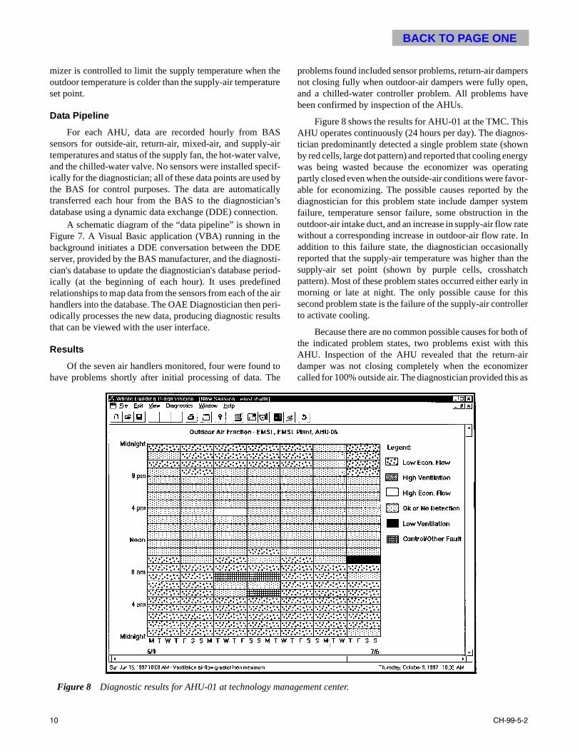
mizer is controlled to limit the supply temperature when theoutdoor temperature is colder than the supply-air temperatureset point.
Data Pipeline
For each AHU, data are recorded hourly from BASsensors for outside-air, return-air, mixed-air, and supply-airtemperatures and status of the supply fan, the hot-water valve,and the chilled-water valve. No sensors were installed specif-ically for the diagnostician; all of these data points are used bythe BAS for control purposes. The data are automaticallytransferred each hour from the BAS to the diagnosticiadatabase using a dynamic data exchange (DDE) connect
A schematic diagram of the “data pipeline” is shown Figure 7. A Visual Basic application (VBA) running in thbackground initiates a DDE conversation between the Dserver, provided by the BAS manufacturer, and the diagnocian's database to update the diagnostician's database peically (at the beginning of each hour). It uses predefinrelationships to map data from the sensors from each of thhandlers into the database. The OAE Diagnostician then podically processes the new data, producing diagnostic resthat can be viewed with the user interface.
Results
Of the seven air handlers monitored, four were foundhave problems shortly after initial processing of data. T
10
n’sion. ineDEsti-riod-ede aireri-ults
tohe
problems found included sensor problems, return-air dampnot closing fully when outdoor-air dampers were fully opeand a chilled-water controller problem. All problems havbeen confirmed by inspection of the AHUs.
Figure 8 shows the results for AHU-01 at the TMC. ThAHU operates continuously (24 hours per day). The diagntician predominantly detected a single problem state (shoby red cells, large dot pattern) and reported that cooling enewas being wasted because the economizer was operapartly closed even when the outside-air conditions were favable for economizing. The possible causes reported bydiagnostician for this problem state include damper systfailure, temperature sensor failure, some obstruction in outdoor-air intake duct, and an increase in supply-air flow rwithout a corresponding increase in outdoor-air flow rate.addition to this failure state, the diagnostician occasionareported that the supply-air temperature was higher thansupply-air set point (shown by purple cells, crosshatpattern). Most of these problem states occurred either earmorning or late at night. The only possible cause for thsecond problem state is the failure of the supply-air controto activate cooling.
Because there are no common possible causes for bothe indicated problem states, two problems exist with tAHU. Inspection of the AHU revealed that the return-adamper was not closing completely when the economicalled for 100% outside air. The diagnostician provided this
Figure 8 Diagnostic results for AHU-01 at technology management center.
CH-99-5-2

BACK TO PAGE ONE
one of the suggested causes (the first problem). The secondproblem (supply-air controller failure to activate cooling)occurs infrequently when the outdoor temperature is lowerthan the supply set point. The building operators are evaluat-ing possible solutions for both problems.
Figure 8 also graphically illustrates that the diagnosticresults depend on outside and operating conditions. Theseconditions determine the mode in which the AHU operatesand, therefore, whether a problem can be observed or not. Forexample, when the outside-air condition is not favorable foreconomizing, the damper problem is not apparent and the cellsare green (small dot pattern). On Wednesday, August 27, thediagnostician identifies (shown by red cells, large dot pattern)that the economizer should not be at part flow from midnightto 10 a.m. At 11 a.m., the cells are green (small dot pattern),when conditions are such that a problem is not apparent. Theunderlying cause, which is the leaky damper described above,has not changed, but the apparent problem that the diagnosti-cian identifies has changed because outside-air conditions andoccupancy changed. The underlying problem was one ofseveral identified as possible by the diagnostician. By observ-ing the diagnostic results over several hours, the operator caninfer the most likely cause of the problem. The ability to auto-matically consider trends to refine the diagnosis, as donemanually for this problem, is currently under development.
Figure 9 shows results for AHU-06 in the EMSL building,which operates continuously, 24 hours per day. The diagnos-
CH-99-5-2
tician detected an operational problem with the AHU, whichwas manifested in three different forms depending on outdoorand operating conditions. Examination of the potential causeslisted for all three states showed a failed return-, mixed-, oroutdoor-air temperature sensor as a common potential cause.
Inspection of the AHU and its sensors revealed that aproblem with the outside-air temperature sensor did indeedexist. Rather than a failure of the sensor itself, however, thelocation and installation of the sensor caused it to read incor-rect air temperatures. It was located in a non-aspirated tubewith the top of the tube sealed and mounted in a corner underan overhang. This arrangement did not allow the air to circu-late adequately. When the walls adjacent to the tube wereheated by sunlight, the sensor indicated a temperature closerto the wall temperature than the air temperature. Because eachAHU in this building has its own outside-air temperaturesensor, this problem can be corrected by simply mapping oneof the other outside-air temperature sensors to this variable inthe BAS.
The results for AHU-02 at TMC showed that the econo-mizer and the ventilation system were working properly, butthe supply-air controller was not controlling the supply-airtemperature properly. This problem is identical to the problemexperienced by the AHU-01 at TMC. The building operatorsare investigating the problem.
Finally, the results from AHU-03 at TMC showedpredominately two problem states: (1) the economizer should
Figure 9 Diagnostic results for AHU-06 at the EMSL building.
11

BACK TO PAGE ONE
the ands—gylica-anle-t ofn,nt
theythealrt-ct
nktheereirthe
g
not be at part flow, and (2) the economizer should not be OFF.In addition to these two states, a few hours existed when thediagnostician reported a temperature sensor failure (detectedby a second-law violation). Further investigation (review ofraw data) and inspection of the AHU revealed that the mixed-air temperature sensor was the problem sensor3.
DISCUSSION AND CONCLUSIONS
The OAE Diagnostician has proven effective in identify-ing outdoor-air ventilation and economizer operation prob-lems in air-handling units during initial field testing.Furthermore, the small sample of air handlers monitored haveconfirmed our suspicion and that of many building operators(CEC 1991) that many economizers do not work as intended.The field test results confirm the suspicion—four of the firseven AHUs monitored had some type of problem. The resalso indicate that automated diagnostic technology promto help identify and eliminate these common problems.
The current version of the OAE Diagnostician is a prottype intended to demonstrate the potential for this technoloand provide a methodology that ultimately can be deployeddifferent ways. For example, the OAE Diagnostician couserve as a tool to support commissioning, routine buildoperation, or equipment servicing. During commissioninthe diagnostician could help ensure that air handlers installed and operating properly. It would process data aidentify problems, which would be eliminated as part of tcommissioning process. To extend its application to supproutine building operation, control system installers or manfacturers could deploy the OAE Diagnostician as an embded part of a control system, BAS, or supervisory softwarethis form, the diagnostician would provide on-demand suppto building operators or facility managers. Operations stcould access diagnostic results as often as desired to supoperation of their facilities. By monitoring air-handler perfomance and diagnosing problems continuously, the diagnocian would ensure that equipment is maintained and operaproperly, providing the equivalent of continuous commissioing. If used at a central location by a manager of several prerties or a campus, the diagnostician could process data several different buildings. This would reduce the frequenof site visits, improve operation and maintenance of handlers, and lower operating costs.
Future developmental work will focus on improving thability of this diagnostician to isolate the cause of probleand direct the building operator to the proper correctactions, as well as extending automated diagnostics to oapplications. In addition to isolating the cause, the futuversion will also highlight the energy and cost impacts dueimproper outdoor air controls or economizer operation. TOAE Diagnostician represents only one application of au
3. All AHUs tested measure the mixed-air temperature across thecross-section of the mixed-air duct and average the value. There-fore, the problem is not caused by stratification, but by using a badsensor data for averaging.
12
stultsises
o-gy inld
ingg,arend
heortu-ed-. Inortaffport
r-sti-tedn-op-
fromcyair
emsivetherre toheto-
mated diagnostics to building equipment and systems. Infuture, automated diagnostic tools could be used to detectdiagnose problems with many components and systemboilers, chillers, variable-air-volume boxes, thermal enerstorage systems—to name only a few. Some of these apptions will require more sophisticated diagnostic methods thused by the OAE Diagnostician. Others may employ the rubased approach used for this diagnostician. Deploymenautomated diagnostics will help improve building operatiobringing improved comfort and air quality, longer equipmelife, and lower costs.
ACKNOWLEDGMENTS
The work described in this paper was sponsored by Office of Building Technology, State and CommunitPrograms of the U.S. Department of Energy as part of Building Systems Program at Pacific Northwest NationLaboratory. The Laboratory is operated for the U.S. Depament of Energy by Battelle Memorial Institute under contraDE-AC06-76RLO 1830. The authors would also like to thatheir colleagues at the Honeywell Technology Center and University of Colorado, who worked on development of othdiagnostic tools as part of the same DOE project, for thinsightful comments as reviewers during development of OAE diagnostic tool.
REFERENCES
ASHRAE. 1995. ANSI/ASHRAE Standard 135-1995, BAC-net™—A data communication protocol for buildinautomation and control networks. Atlanta: AmericanSociety of Heating, Refrigerating and Air-ConditioningEngineers, Inc.
Brambley, M., R. Pratt, D.P. Chassin, and S. Katipamula.1998. Automated diagnostics for outdoor air ventilationand economizers. ASHRAE Journal 40(10).
CEC. 1991. Nonresidential standards confidence & sensitiv-ity analysis. Building and Appliance Efficiency Office,California Energy Commission, Sacramento.
Friedrich, M., and M.T. Messinger. 1995. Method to assessthe gross annual savings potential of energy conserva-tion technologies used in commercial buildings.ASHRAE Transactions 101(1): 444-453.
Haves, P., T.I. Salisbury, and J.A. Wright. 1996. Conditionmonitoring in HVAC subsystems using first-principlemodels. ASHRAE Transactions 102(1): 519-539.
LBNL. 1989. DOE-2 engineering manual, Version 2.1E.LBL-8688. Energy and Environment Division, BuildingEnergy Simulation Group, Lawrence Berkeley NationalLaboratory, University of California, Berkeley.
Lee, W.Y., J.M. House, and D.R. Shin. 1997. Fault diagnosisand temperature sensor recovery for an air-handlingunit. ASHRAE Transactions 103(1): 621-633.
Li, X., J-C. Visier; and H. Vaezi-Nejad. 1997. A neural net-work prototype for fault detection and diagnosis of heat-ing systems. ASHRAE Transactions 103(1): 634-643.
CH-99-5-2

BACK TO PAGE ONE
Peitsman, H.C., and L.L. Soethout. 1997. ARX models andreal-time model-based diagnosis. ASHRAE Transactions103(1): 657-671.
Rossi, T.M., and J.E Braun. 1997. A statistical, rule-basedfault detection and diagnostic method for vapor com-
CH-99-5-2
pression air conditioners. HVAC&R Research 3(1): 19-37.
Stylianou, M. 1997. Application of classification functionsto chiller fault detection and diagnosis. ASHRAE Trans-actions 103(1): 645-656.
13