automated juggler - rensselaer polytechnic institute
TRANSCRIPT

Automated Juggler
Team 7John CarpenterShannon Jordan
Dan Grover
Objective
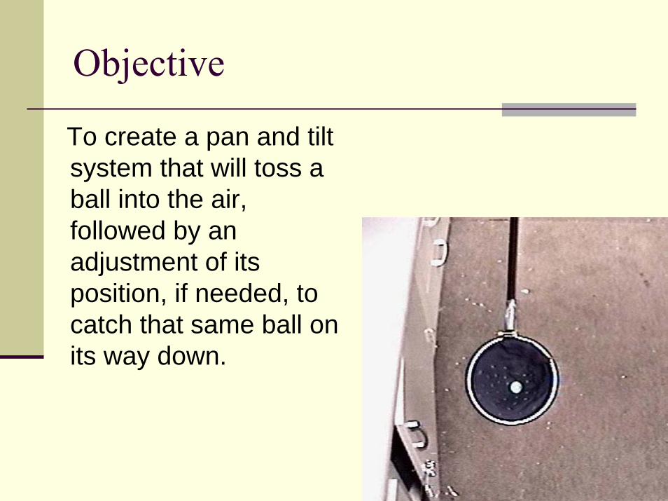
To create a pan and tilt system that will toss a ball into the air, followed by an adjustment of its position, if needed, to catch that same ball on its way down.

Performance SpecificationThe system’s first goal is to throw a ball 1 meter vertically into the air,and catch it on its way down. Using a gear ratio of 3:2, a throwing radius of 0.7908 meters, and a 4 inch diameter “pouch”, the arm will lower 1.2645 radians from a horizontal position, and accelerate at approximately 12.4 rad/s2 at the shaft gear, meaning the motor itself needs to accelerate 8.07 rad/s2. Once the arm is back to its horizontal position, it begins decelerating, causing the ball to launch. It then returns to the horizontal position and waits for the ball to return in order to catch it.
The next goal of the system is to launch the ball forward, approximately twice the length of the arm, and promptly pan around at a maximum speed of 6.0 rad/s in order to catch the ball as it descends on the other side.
Professional and Societal Consideration
The idea of a control system used to launch an object can be applied to many situations, primarily mechanical systems that could resemble a catapult. The systems could vary, including an automatic ball launching machine (pitching machine), for example, ping pong, tennis, or softball, that one could use to practice sports alone, basic military firing equipment, or a satellite launcher that implements gravity assist.
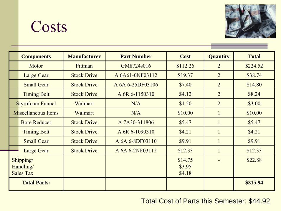
CostsComponents Manufacturer Part Number Cost Quantity Total
Motor Pittman GM8724s016 $112.26 2 $224.52
Large Gear Stock Drive A 6A61-0NF03112 $19.37 2 $38.74
Small Gear Stock Drive A 6A 6-25DF03106 $7.40 2 $14.80
Timing Belt Stock Drive A 6R 6-1150310 $4.12 2 $8.24
Styrofoam Funnel Walmart N/A $1.50 2 $3.00
Miscellaneous Items Walmart N/A $10.00 1 $10.00
Bore Reducer Stock Drive A 7A30-311806 $5.47 1 $5.47
Timing Belt Stock Drive A 6R 6-1090310 $4.21 1 $4.21
Small Gear Stock Drive A 6A 6-8DF03110 $9.91 1 $9.91
Large Gear Stock Drive A 6A 6-2NF03112 $12.33 1 $12.33
Shipping/Handling/Sales Tax
$14.75$3.95$4.18
- $22.88
Total Parts: $315.94
Total Cost of Parts this Semester: $44.92
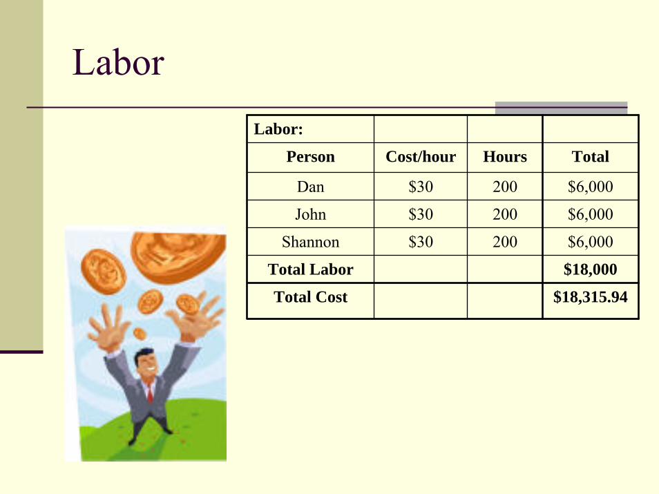
LaborLabor:
Person Cost/hour Hours Total
Dan $30 200 $6,000
John $30 200 $6,000
Shannon $30 200 $6,000
Total Labor $18,000
Total Cost $18,315.94
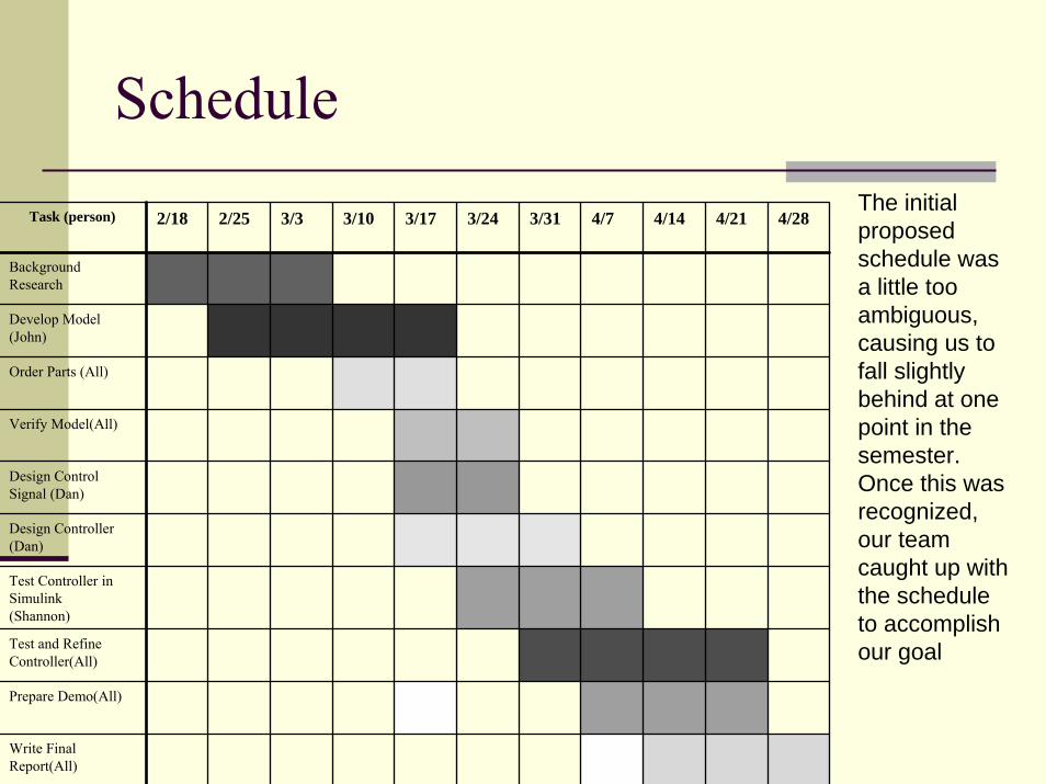
ScheduleThe initial proposed schedule was a little too ambiguous, causing us to fall slightly behind at one point in the semester. Once this was recognized, our team caught up with the schedule to accomplish our goal
Task (person) 2/18 2/25 3/3 3/10 3/17 3/24 3/31 4/7 4/14 4/21 4/28
Background Research
Develop Model (John)
Order Parts (All)
Verify Model(All)
Design Control Signal (Dan)
Design Controller (Dan)
Test Controller in Simulink(Shannon)
Test and Refine Controller(All)
Prepare Demo(All)
Write Final Report(All)
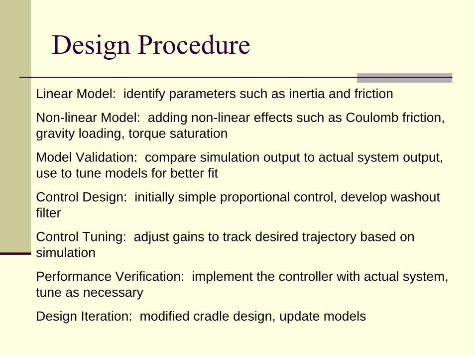
Design ProcedureLinear Model: identify parameters such as inertia and friction
Non-linear Model: adding non-linear effects such as Coulomb friction, gravity loading, torque saturation
Model Validation: compare simulation output to actual system output, use to tune models for better fit
Control Design: initially simple proportional control, develop washout filter
Control Tuning: adjust gains to track desired trajectory based on simulation
Performance Verification: implement the controller with actual system, tune as necessary
Design Iteration: modified cradle design, update models
Modifications of Mechanical SystemIn order to increase the possible angular velocity of the system, two new gears were purchased in order to decrease the initial 4:1 gear ratio of the tilt motor. The larger gear has a 0.935 inch diameter, while the smaller one has a 0.609 inch diameter, resulting in a 3:2 gear ratio.
In addition, to increase the velocity at which the ball itself will be launched, a longer rod, 0.7400 meters, as opposed to the previous 0.2794 meters, was implemented in the final design.
A new cradle was also implemented in order to minimize the effect of ball bounce. It was made with a 4 inch diameter wooden hoop, and a slightly elastic fabric pouch.
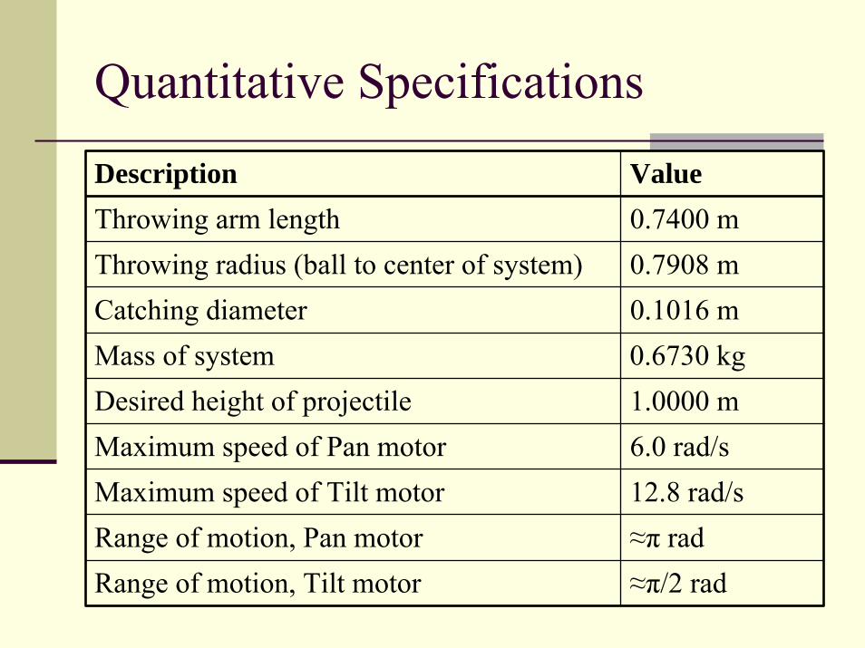
Quantitative Specifications
Description ValueThrowing arm length 0.7400 mThrowing radius (ball to center of system) 0.7908 mCatching diameter 0.1016 mMass of system 0.6730 kgDesired height of projectile 1.0000 mMaximum speed of Pan motor 6.0 rad/sMaximum speed of Tilt motor 12.8 rad/sRange of motion, Pan motor ≈π radRange of motion, Tilt motor ≈π/2 rad
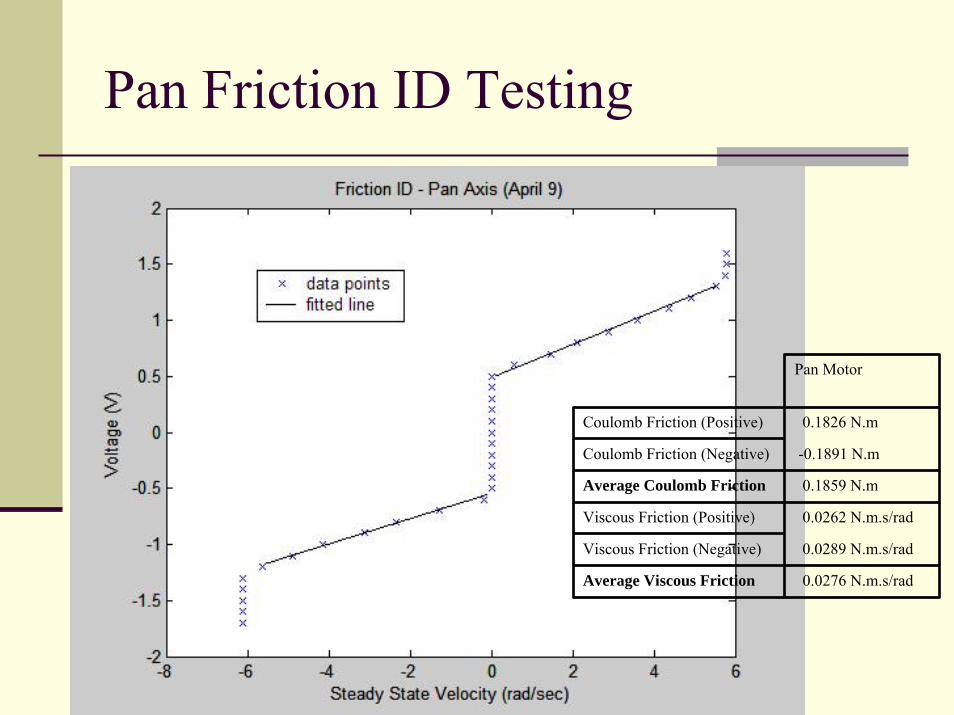
Pan Friction ID Testing
Pan Motor
Coulomb Friction (Positive) 0.1826 N.m
Coulomb Friction (Negative) -0.1891 N.m
Average Coulomb Friction 0.1859 N.m
Viscous Friction (Positive) 0.0262 N.m.s/rad
Viscous Friction (Negative) 0.0289 N.m.s/rad
Average Viscous Friction 0.0276 N.m.s/rad
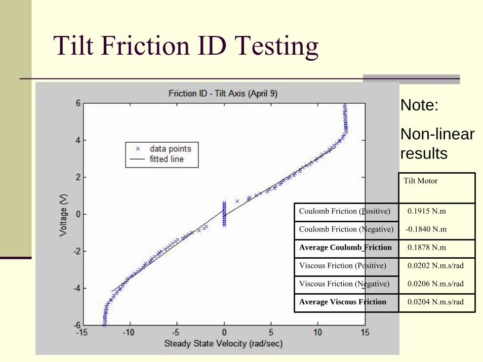
Tilt Friction ID Testing
Note:
Non-linear resultsTilt Motor
Coulomb Friction (Positive) 0.1915 N.m
Coulomb Friction (Negative) -0.1840 N.m
Average Coulomb Friction 0.1878 N.m
Viscous Friction (Positive) 0.0202 N.m.s/rad
Viscous Friction (Negative) 0.0206 N.m.s/rad
Average Viscous Friction 0.0204 N.m.s/rad
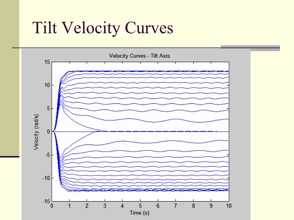
Tilt Velocity Curves
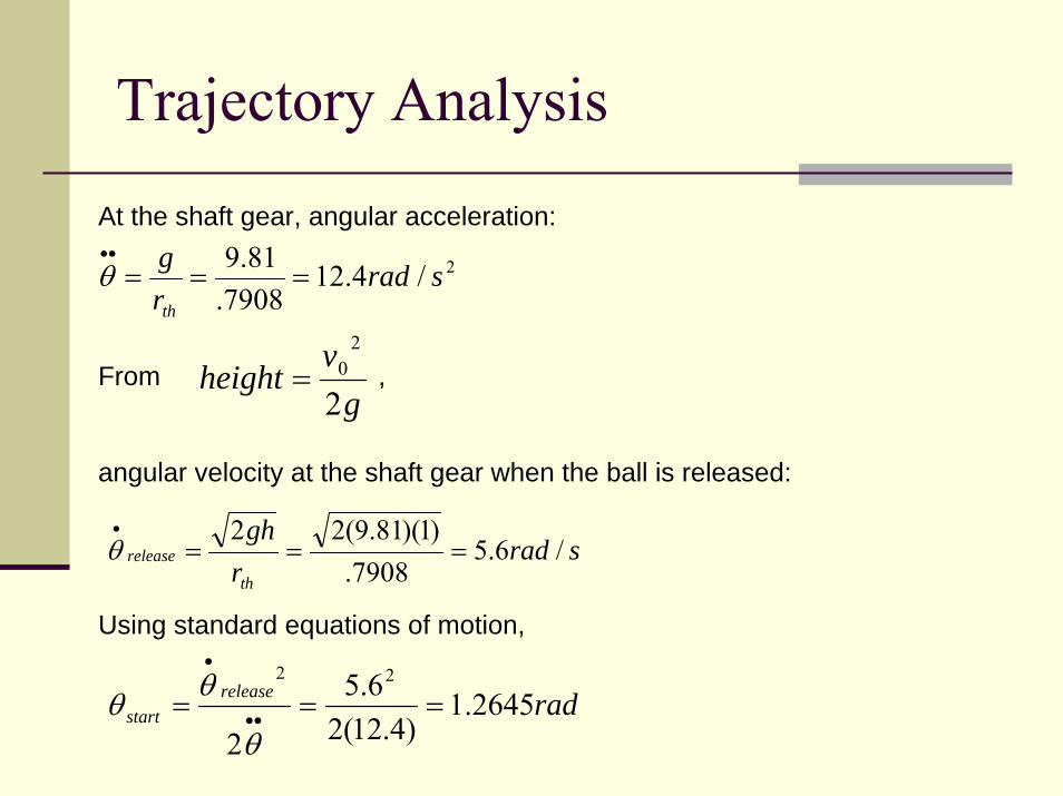
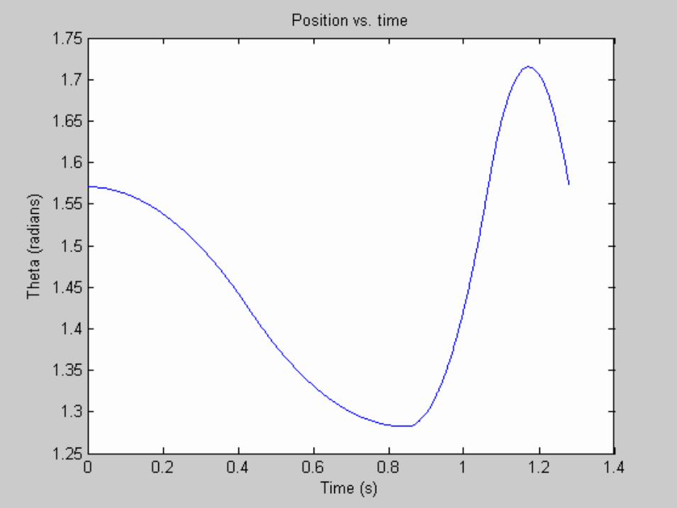
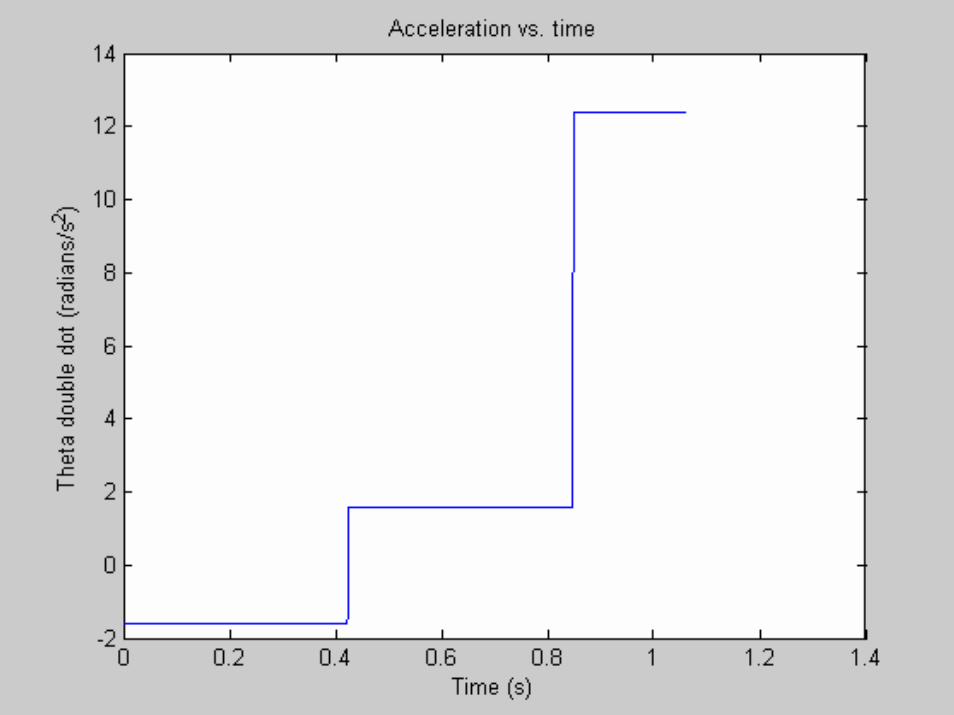
Trajectory Analysis
At the shaft gear, angular acceleration:
From ,
angular velocity at the shaft gear when the ball is released:
gv
height2
20=
2/4.127908.
81.9 sradrg
th
===••
θ
sradrgh
th
release /6.57908.
)1)(81.9(22===
•
θ
radreleasestart 1.2645
)4.12(26.5
2
22
=== ••
•
θ
θθ
Using standard equations of motion,
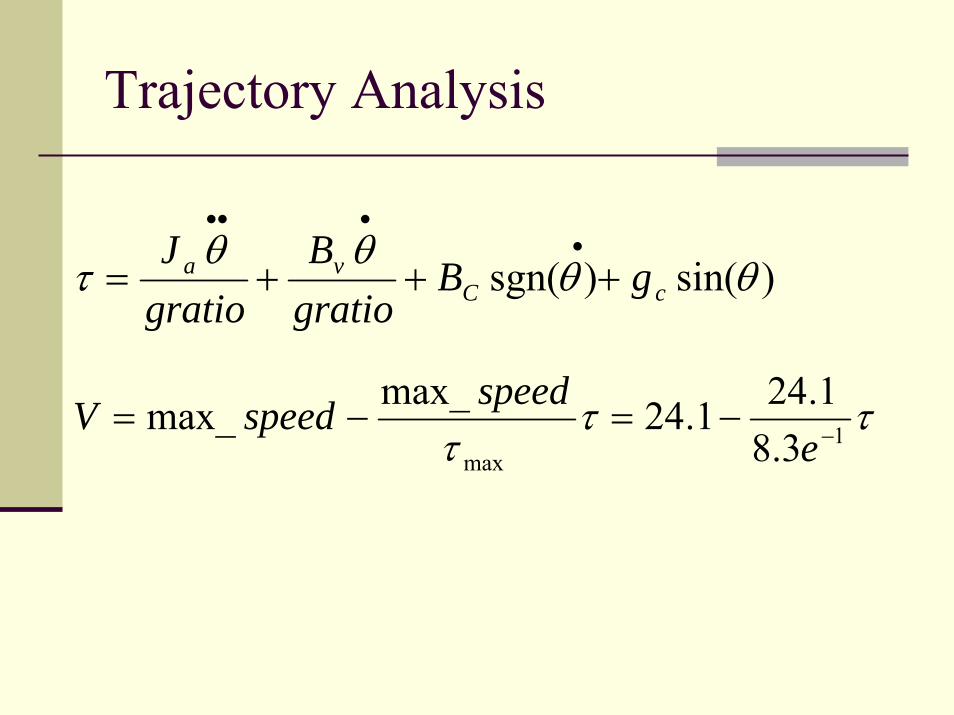
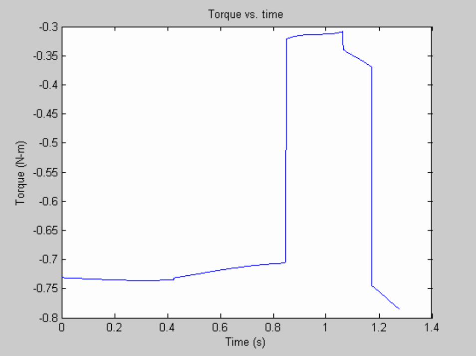
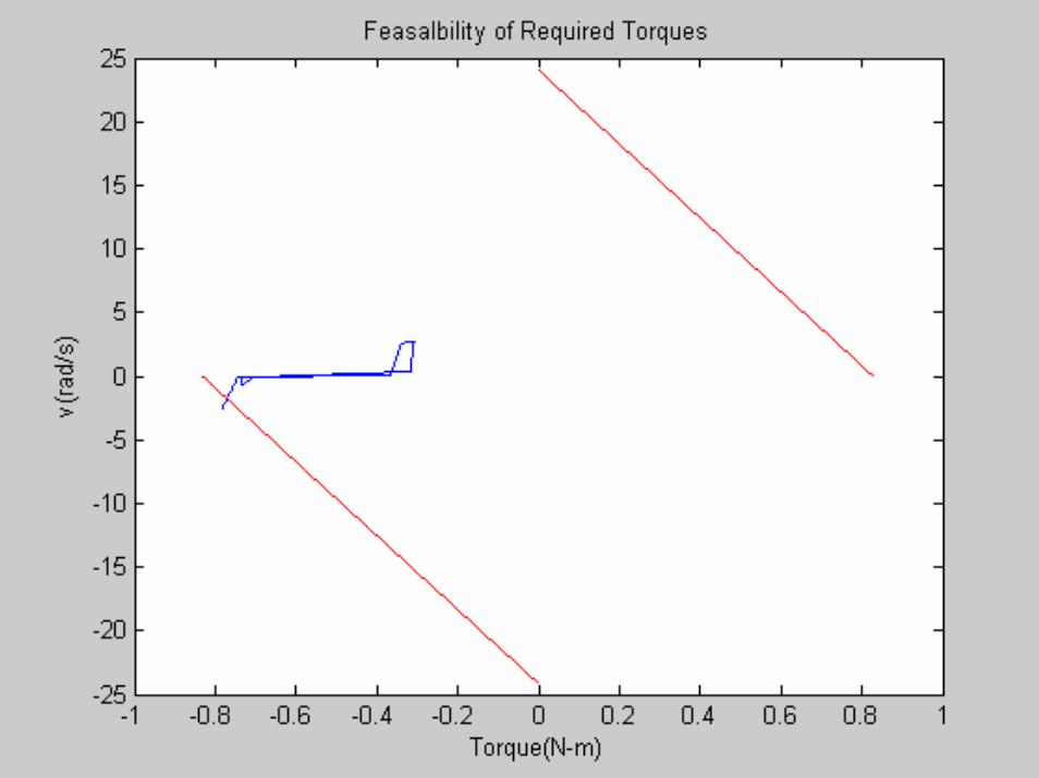
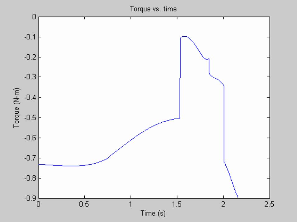
Trajectory Analysis
)sin()sgn( θθθθ
τ cCva gB
gratioB
gratioJ
+++=•
•••
τττ 1
max 3.81.241.24max_max_ −−=−=
espeedspeedV
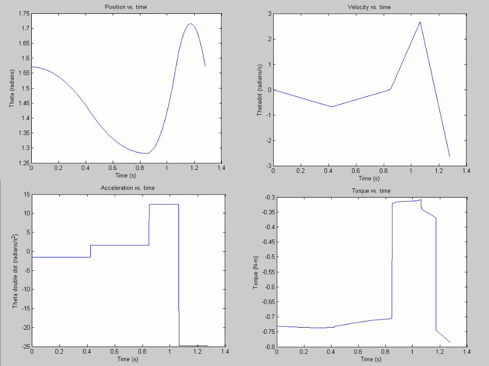
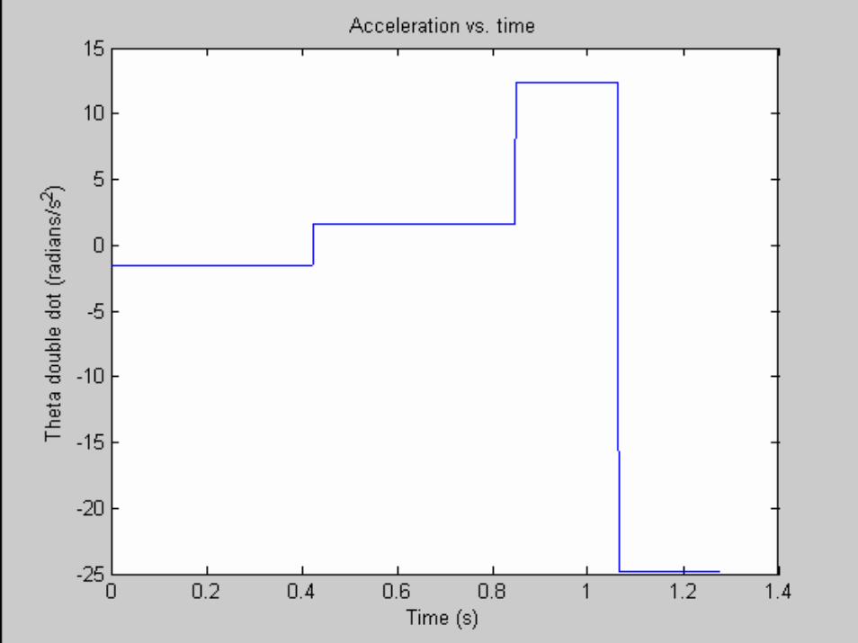


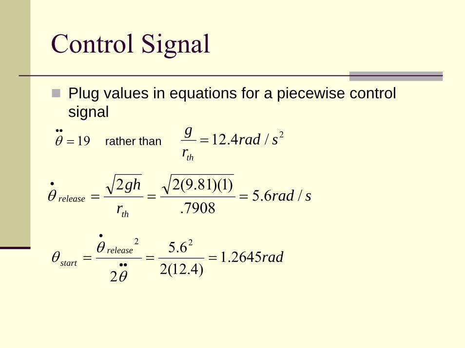
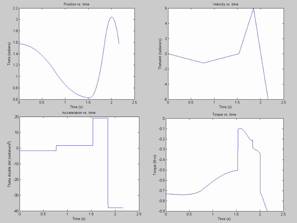
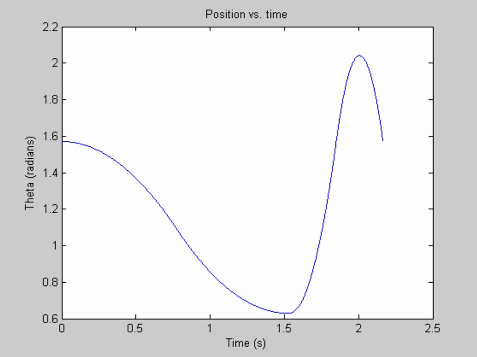
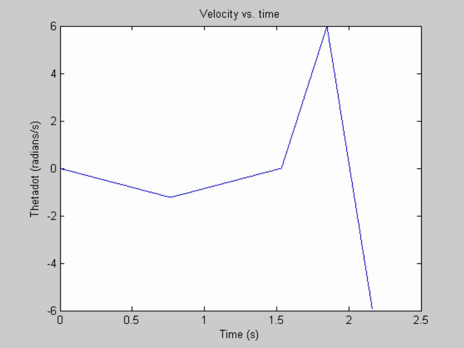
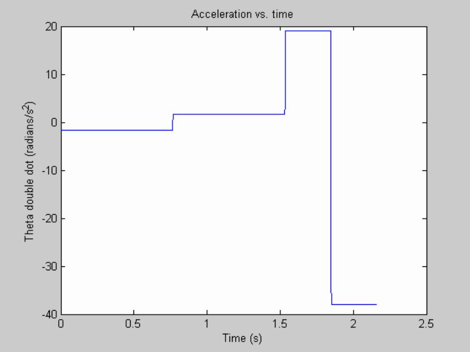
Control Signal
Plug values in equations for a piecewise control signal
19=••
θ rather than 2/4.12 sradrg
th
=
sradrgh
th
release /6.57908.
)1)(81.9(22===
•
θ
radreleasestart 1.2645
)4.12(26.5
2
22
=== ••
•
θ
θθ
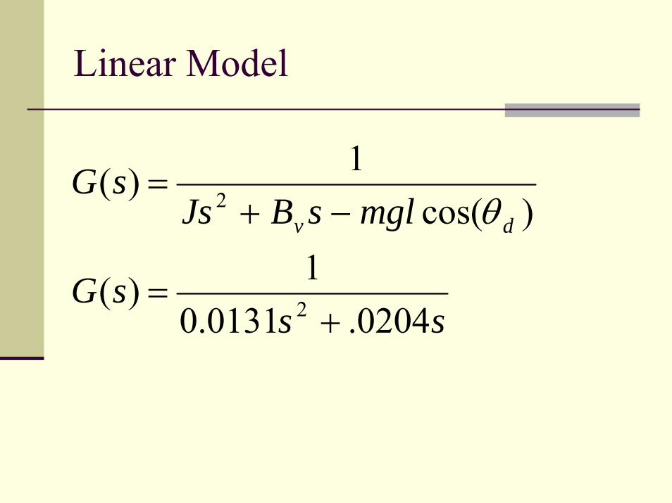
Linear Model
sssG
mglsBJssG
dv
0204.0131.01)(
)cos(1)(
2
2
+=
−+=
θ
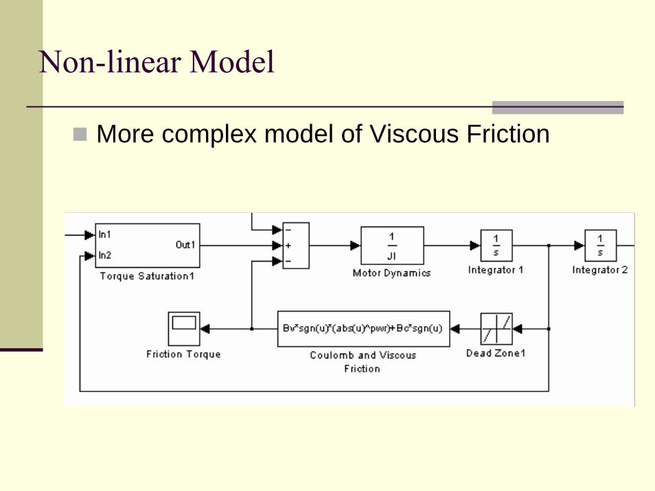
Non-linear Model
More complex model of Viscous Friction
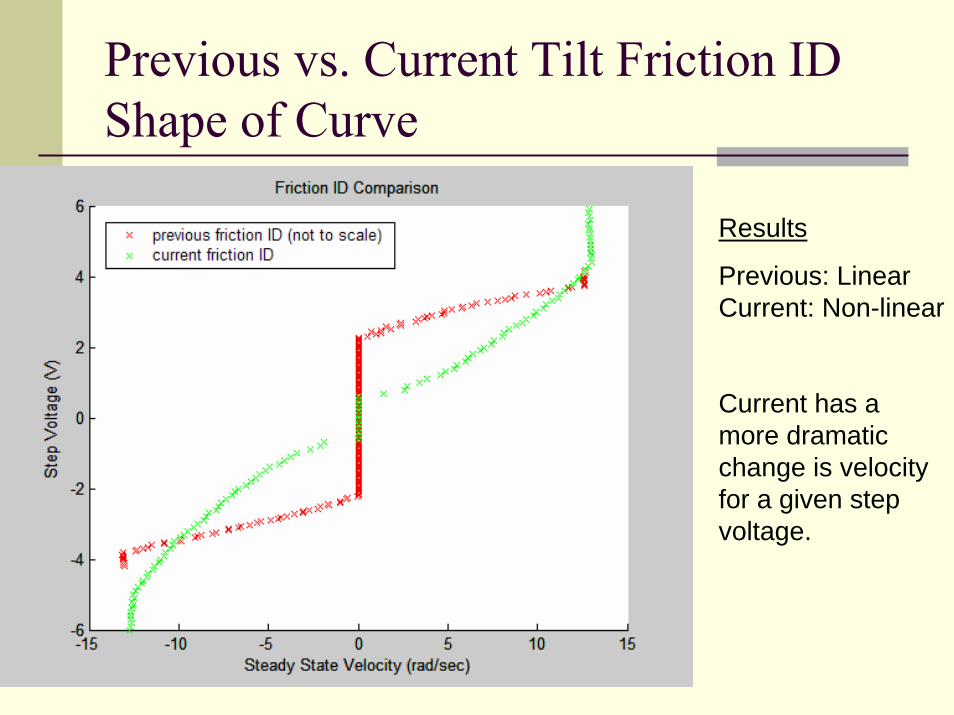
Previous vs. Current Tilt Friction ID Shape of Curve
Results
Previous: Linear Current: Non-linear
Current has a more dramatic change is velocity for a given step voltage.
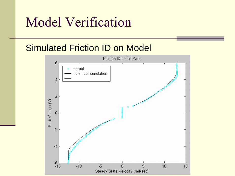
Model Verification
Simulated Friction ID on Model
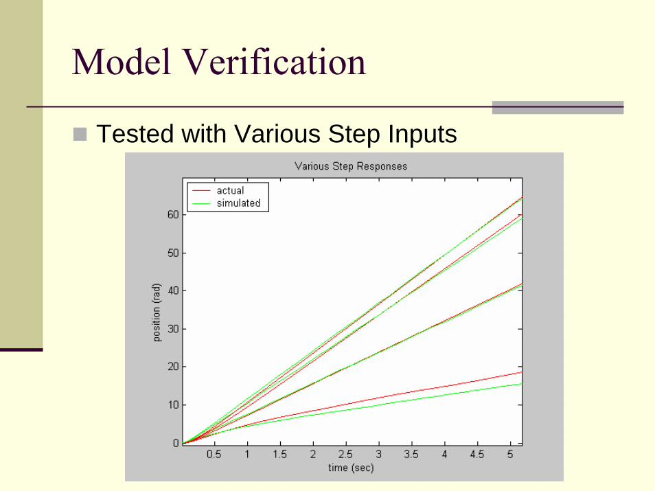
Model Verification
Tested with Various Step Inputs
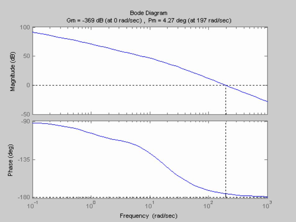
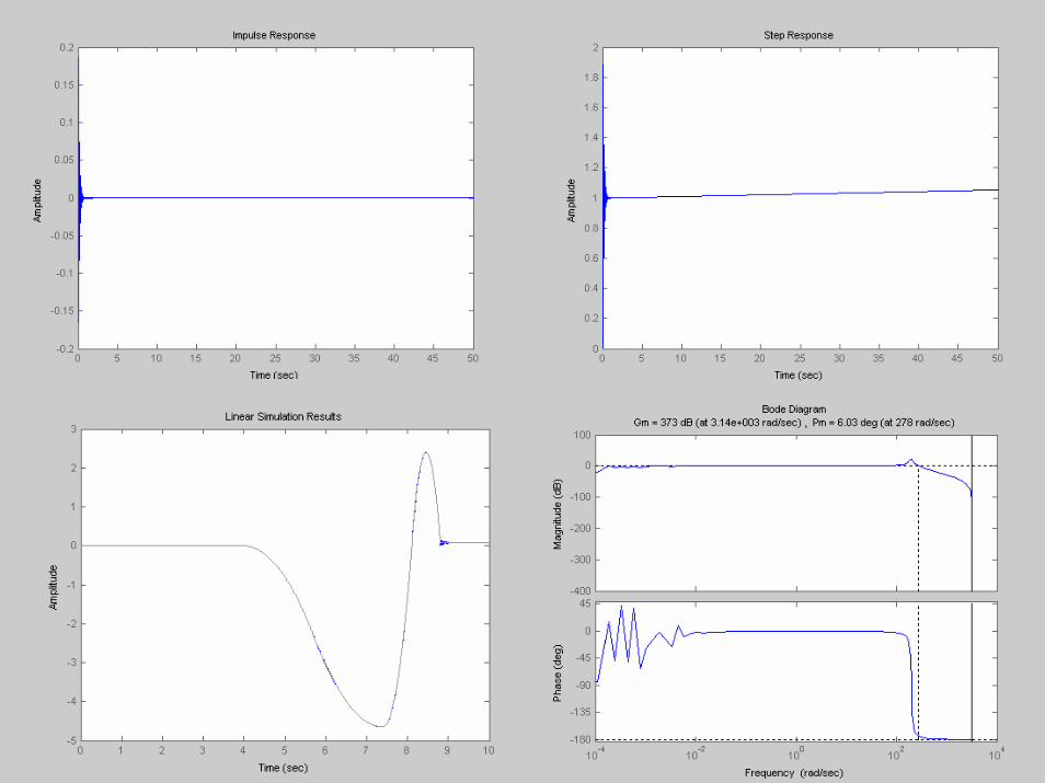
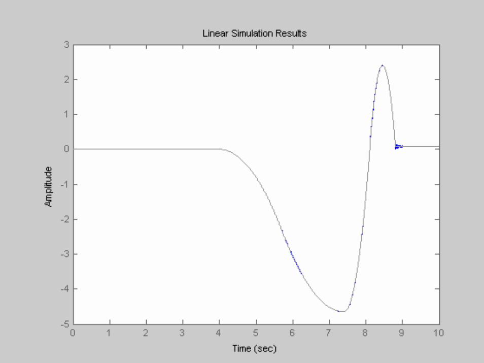
Controller Design (Linear Continuous)
1064.141.*80)(++
=s
ssC
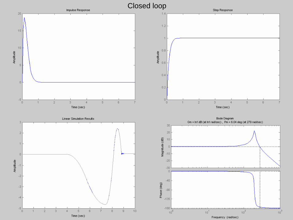
Closed loop
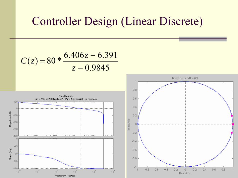
Controller Design (Linear Discrete)
9845.0391.6406.6*80)(
−−
=z
zzC
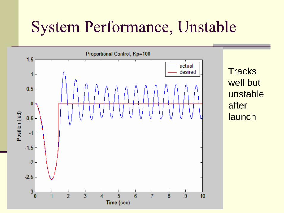
System Performance, Unstable
Tracks well but unstable after launch
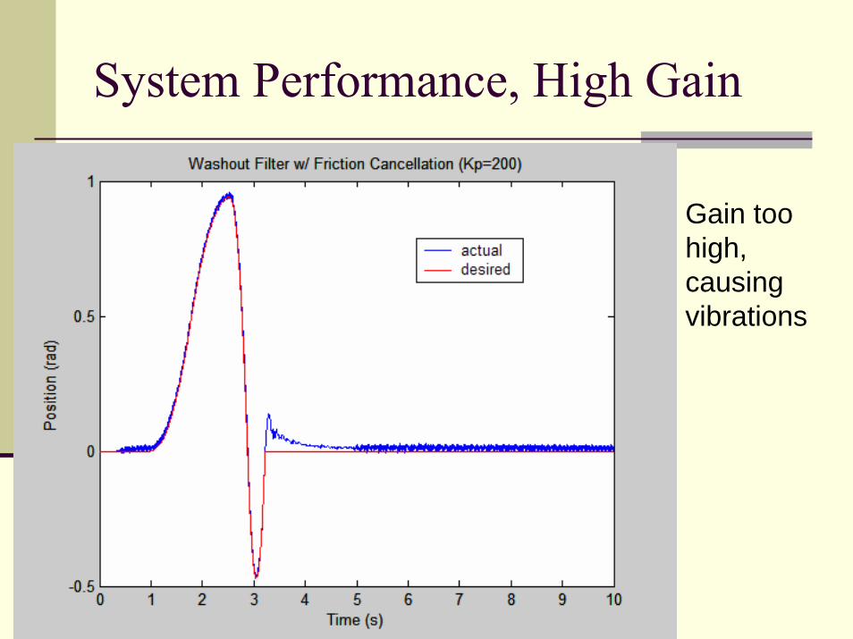
System Performance, High Gain
Gain too high, causing vibrations
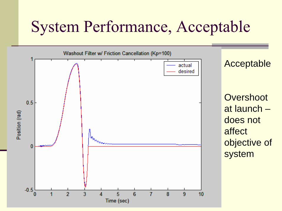
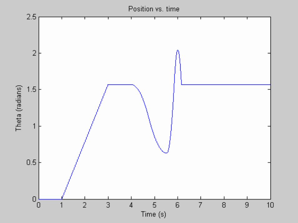
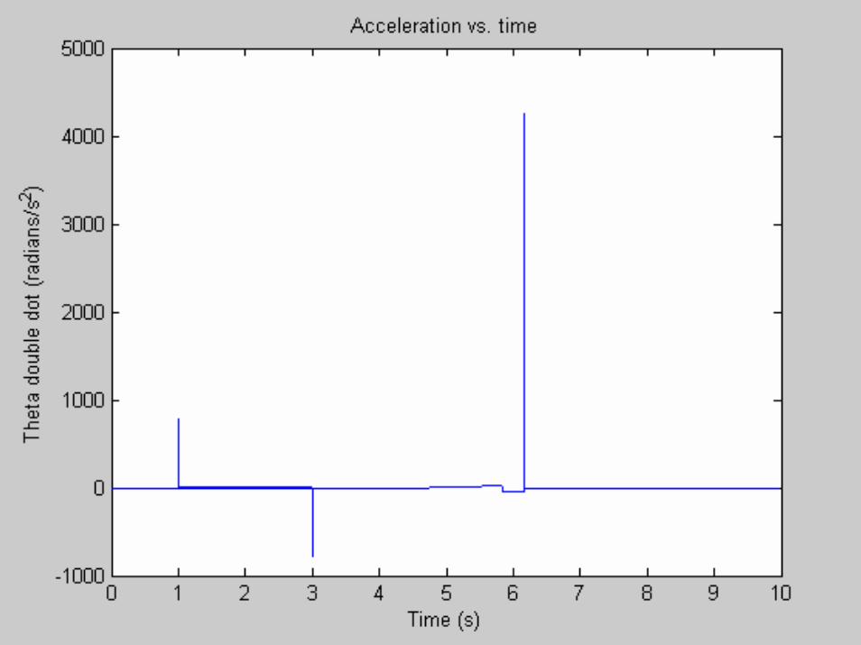
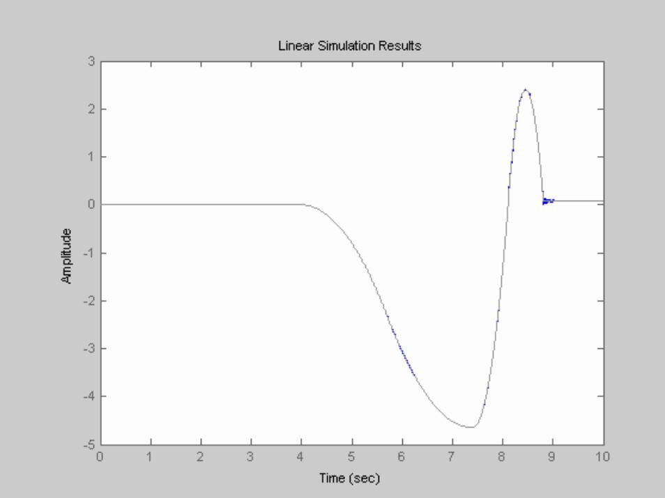
System Performance, Acceptable
Acceptable
Overshoot at launch –does not affect objective of system
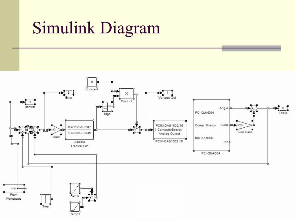
Simulink Diagram
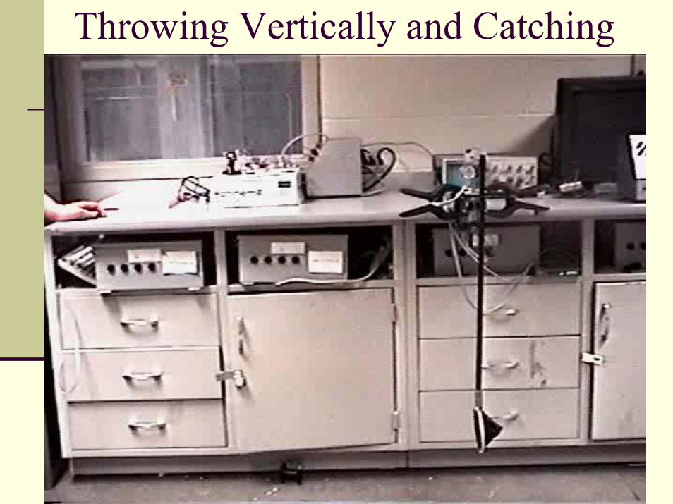
Throwing Vertically and Catching
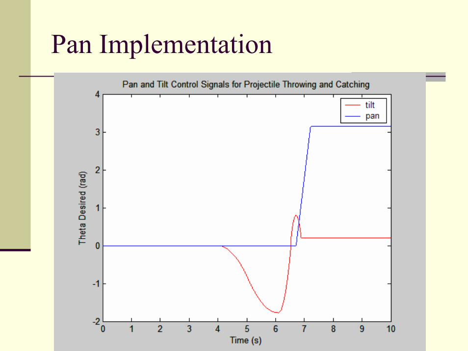
Pan Implementation
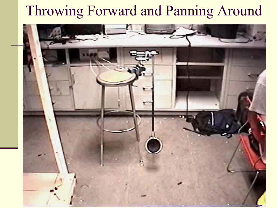
Throwing Forward and Panning Around
Recommendations and Enhancements
Use a ball with lower coefficient of restitution
Design a cradle that is stiff, sturdy, and shock absorbing in order to increase consistency of the toss
Mount throwing arm so that it is centered with the pan axis
Attach an electric level (inclinometer) to the tilt axis in order to accurately initialize the system
Add sensors to track ball and correct for error
Juggle multiple balls at once
Extend original arm so that there is a cradle on each side
Have two separate systems, and coordinate their activities
ConclusionThe initial goal of catching a vertical toss was achieved and recorded
The enhanced goal of using the pan motor to quickly spin around and catch the ball was implemented
More difficult than had initially planned, as the arm is not centered about the tilt axis
May have been achieved had time permitted
A few recommendations and enhancements were suggested in order to refine and update the system in the future