automated softening point tester model asp-5 instruction ... instruction 1.10.pdf · "standard...
TRANSCRIPT

Automated Softening Point Tester
Model ASP-5
Instruction Manual
Ver. 1.10 070913
Read this manual thoroughly before using the product, and store in a safe place for future reference.
TANAKA SCIENTIFIC LTD, TOKYO, JAPAN

1
FOREWORD
Thank you for purchasing the Automated Softening Point Tester Model ASP-5 from Tanaka Scientific Limited. This instruction manual provides necessary information for using the ASP-5. Read this manual thoroughly before use and ensure that you have understood its contents. This manual employs the following precautionary notation. For your safety, ensure that you understand these precautions and heed them at all times.
! WARNING:・・・・・・・・・・
Warnings indicate a significant risk of death or serious physical injury if the information is ignored.
! CAUTION:・・・・・・・・・・
Cautions indicate a significant risk of physical injury or property damage if the information is ignored.
USES
! Warning: This product is only to be used to measure
softening points as prescribed in ASTM D36 "Standard Test Methods for Softening Point of Bitumen (Ring-and-ball Apparatus)"
This product automates the testing procedures prescribed in ASTM D36 "Standard Test Methods for Softening Point of Bitumen (Ring-and-ball Apparatus)" for the measurement of softening points, and is not to be used for any other purpose.

2
ABOUT THIS INSTRUCTION MANUAL ● This manual is intended for all operators of the ASP-5.
The reader is assumed to have sufficient knowledge of ASTM procedures and standards as well as knowledge of the correct handling procedures for hazardous materials.
● The content this manual is subject to change without notice due to enhancements to the performance and functionality of the instrument.
● If this manual is lost or damaged, contact Tanaka Scientific Limited or an authorized distributor for a replacement copy.
● The contents of this manual have been thoroughly reviewed. If any pages are missing, out of order, or the manual contains spelling, grammatical or descriptive errors, please contact Tanaka Scientific Limited or an authorized distributor.
BEFORE USE
● Before using the product, ensure that you have read this manual thoroughly and have understood all of the content. If you have any questions, be sure to contact Tanaka Scientific Limited or an authorized distributor.
● Keep this manual in a safe, easily accessible place.
● This product is to be used for its intended purpose only. Adhere strictly to all procedures given in this manual.
● Ensure that you understand and abide by all warnings and cautions given in this manual.

3
WARNINGS AND CAUTIONS FOR SAFE USE Failure to follow all of the warnings and cautions listed below may result in damage to the instrument and/or serious personal injury. Tanaka Scientific Limited will not assume any responsibility for faults or accidents arising from failure to adhere to these instructions.
Installation Environment
! Warning: The instrument must be installed in a
well-ventilated environment. As samples release inflammable and/or toxic gases, inadequate ventilation may result in poisoning.
! Warning: The instrument must be installed on a flat, sturdy
surface to prevent the instrument from falling over.
Electric Connection
! Warning: Observe the following instructions when handling
power cables and electric connections:
・ Do not connect or disconnect any cables or electrical connections when the mains power is ON.
・ Do not handle any cables or electrical connections with wet hands.
・ Be sure to use the plug to remove cables. Never use the cord to pull a plug from an outlet.
・ Do not place heavy items on cords or cable. ・ Do not use force to bend any cords or cables. ・ Ensure that all electric connections (plugs,

4
sockets, connectors, etc.) are free of dust. ・ Keep all cables and electrical connections free
of water and other liquids.
・ Failure to adhere to the above precautions may result in electric shock, damage to the instrument, cords and/or cables, and/or fire due to overheating.
! Warning: Ensure that supply voltage meets the
specifications of the product. Do not turn the power on until all electric connections are secured. Incorrect power supply specifications or loose electric connections may damage the instrument and result in electric shock and/or other electrical accidents.
! Warning: Ensure all ground wires are securely grounded.
Loose or disconnected ground wires may result in electric shock.
Never connect ground wires to gas pipes, as this may result in fire or an explosion.
Ground wires may be connected to one of the following:
・ Ground terminal of a power outlet ・ Copper bar buried 65 cm or more underground
Handling Precautions
! Caution: Be sure to review the expected aniline point
setting prior to each test run. If the expected aniline point is not entered, or is much greater than the actual aniline point, great volumes of pyrolysis gas or other toxic vapors may be produced due to the increased testing

5
time required.
! Warning: Never discard hot samples.
If a hot sample is discarded into a container containing low flash point waste oil, a fire or explosion may result.
Operational Precautions
! Warning: Never touch the bottom section of the measuring
cell (made of glass) while the instrument is running. The cell is heated to high temperatures during operation and can cause serious burns.
! Warning: The instrument is not to be operated unattended.
Great danger exists if the instrument falls or is knocked over. For safety reasons, an operator should always be in the same room as the running instrument.
! Warning: If the instrument makes any abnormal noises or
exhibits any abnormal behavior, stop operation immediately, turn the power off at the mains, and contact Tanaka Scientific Limited or an authorized distributor.
Consumables, Accessories and Replacement Parts
! Caution: Use only Tanaka Scientific Limited genuine
consumables, parts and accessories or such parts as recommended by Tanaka Scientific Limited.

6
Repairs, Alterations and Maintenance
! Warning: Do not make any modifications or alterations to
the instrument without the approval of Tanaka Scientific Limited.
! Warning: Do not attempt to repair the instrument yourself. In
the event that the instrument exhibits any abnormal behavior whatsoever, contact Tanaka Scientific Limited or an authorized distributor.
! Warning: Only Tanaka Scientific Limited service personnel
or authorized representatives are to repair or maintain the instrument.

7
Contents
FOREWORD ........................................................................................................................1
USES....................................................................................................................................1
ABOUT THIS INSTRUCTION MANUAL ...............................................................................2
BEFORE USE.......................................................................................................................2
WARNINGS AND CAUTIONS FOR SAFE USE ...................................................................3
Contents ...............................................................................................................................7
1 Section Name and Functions .....................................................................................8
2 Installation................................................................................................................10
2.1 Installation Environment....................................................................................10
2.2 Electric Connections .........................................................................................10
3 Checking the Instrument Daily before Use...............................................................12
4 Preparing to Begin Testing .......................................................................................13
4.1 Preparing a Sample (1)......................................................................................13
4.2 Preparing the Bath Liquid (2).............................................................................13
5 Test Procedure.........................................................................................................14
5.1 Activating the Tester..........................................................................................14
5.2 Selecting the Test Mode....................................................................................15
5.3 Setting Ring Holder and Temperature Sensor...................................................16
5.4 Test Start ...........................................................................................................16
5.5 Test End............................................................................................................19
5.5.1 Normal end ................................................................................................19
5.5.2 Abnormal Termination................................................................................20
5.6 Removing the Temperature Sensor ..................................................................20
6 Data Storage Functionality .......................................................................................21
7 Parts Replacement and Self-inspection ...................................................................22
7.1 Consumables and Spares.................................................................................22
7.2 Periodic Inspection and Adjustment ..................................................................22
8 Troubleshooting (Self-diagnosis Function) ...............................................................23
9 After-sales Service ...................................................................................................24
10 If This Manual is Lost............................................................................................24
11 Transferring the Tester..........................................................................................24
12 Disposing of the Tester .........................................................................................24
13 Specifications .......................................................................................................25
Product Warranty ................................................................................................................27

8
1 Section Name and Functions The tester consists of a control unit and a test unit (see Fig.1) that are connected by two
cables.
Fig.1 Overview of ASP-5 Mains Switch: Turns power to the tester ON or OFF. Control Panel: Has various setting keys and operation switches. (See Fig.2) Display: A fluorescent panel that displays test parameters, status, and
results. (see Fig.2) Heater Output Indicator: Flashes whenever the heater is on during testing. Ring Holder and Bottom Plate Assembly: Holds the shouldered rings and the temperature sensor. Ring Holder Assy Stand: The ring holder and bottom plate assy is mounted here during
testing. Auxiliary Ring Holder Assy Stand:
The ring holder and bottom plate assembly is mounted here whenever not testing.
Ring Drip Tray: A drip tray for when the ring holder and bottom plate assembly is mounted on the auxiliary ring holder assy stand.
Temperature Sensor: Detects the bath liquid temperature. Temperature Sensor Bracket: A bracket with which the height of the temperature sensor can
be adjusted using a setscrew. Temperature Sensor Holder: The temperature sensor is stored here when not being used. Bath (Beaker): Filled with the bath liquid suitable for the test. Light Projector: An incandescent lamp used during tests. Light Receiver: A light-sensor for detecting light from the incandescent lamp.
ASP-5 AUTOSOFTENINGPOINT
Temperature Sensor
Temperature Sensor Bracket
Ring Holder and Bottom Plate Assembly
Temperature Sensor Holder
Shield
Heater Output Indicator
Control Panel
Display
Ring Holder Assy Stand
Bath (Beaker)
Lamp cover
Auxiliary Ring Holder Assy Stand
Ring drip tray
Mains Switch
Light Receiver Cover
(Projector)
(Receiver)
Test Unit
Control Unit

9
(1) Fluorescent Display (5) START Key (9) Right/left Key
(2) COOL Lamp (6) COOL Key (10) Up/down Key
(3) RUN Lamp (7) RESET Key (11) FUNCTION Key
(4) MODE Key (8) CHECK Key
Fig. 2 Control Unit Display Panel
Fluorescent Display: Displays test mode, bath liquid temperature, softening point, measured temperatures and error messages. The contents of the display can be changed by pressing the CHECK key.
MODE Key: Alternates the test mode between water bath and glycerin bath. START Key: Starts a test. RUN Lamp: Lights up during a test. COOL Key: Starts the cooling fan. RESET Key: Resets the tester by aborting any testing or cooling operations. CHECK Key: Changes the current screen displayed, toggles between:
Main Screen: Shows bath liquid temperature (uppercase), test mode and sequence status
Sub Screen: Shows light projection, light reception, drop detection level, heater output, bath liquid temperature (lowercase), temperature rise rate, and sequence status
Left/Right Keys: Used to move the cursor when changing the sample name or internal settings.
Up/Down Keys: Used to change the sample name or internal settings. FUNCTION Key: Displays the previous softening point or the measuring range.
FUNC TION
MODE STARTCOOL
WARM RESET CHECK
RUN
(1)
(2)
TANAKA SOFTENING POINT CONTROL UNIT
(3)
(4) (5) (6) (7) (8) (9) (10)
(11)

10
2 Installation 2.1 Installation Environment
! Warning: For the glycerin bath, install the tester in a location
fitted with a draft chamber or equivalent exhaust facilities. Glycerin vapor may generate harmful aldehydes.
! Caution: Never install the tester in direct sunlight or strong light,
as this may cause the tester to behave abnormally.
Normally, the test unit is installed on top of the control unit, with the two units connected by
the standard 0.6 meter cable. The pair of units should then be installed on an indoor, stable,
level table with minimal exposure to drafts.
When installing the test unit in a draft chamber separate from the control unit, use the
optional 3-meter connection cable and install the control unit in a place where it is
convenient to operate the unit.
Avoid environments in which any of the following are present:
- High temperatures (>40°C)/ low temperatures (<0°C) or high humidity (>90%)
- Direct sunlight or strong light beam
- Dust
- Rapid temperature changes
2.2 Electric Connections
! Warning: To prevent electric shock, be sure to connect the
ground wire. Never connect the ground wire to a gas pipe, as this may cause a fire or explosion.
The ground wire may be connected to any of the following:
- The ground terminal of an outlet
- A copper bar buried 65 cm or more under the ground
(1) To connect the control and test units, plug the two cables (power cable and signal cable) into the sockets on the backs of the units.
(2) Insert the temperature sensor plug (3P) into the socket on top of the test unit.

11
Make sure that the element side of the temperature sensor is inserted in the temperature sensor holder.
(3) Plug the power cord into the back of the control unit and insert the power plug AC outlet. The power consumption of model ASP-5 is 1.7 kW(max, @120V). When sharing a single outlet with other electric appliances, take care to ensure that the total power consumption does not exceed the capacity of the outlet.
Fig. 3 Back of ASP-5
Lead Wire for Temperature Sensor
Temperature Sensor
Mains Switch
Signal Cable
RS-232C Socket
Power Cable AC Power Cord
Circuit Protector
Electrical Outlet

12
3 Checking the Instrument Daily before Use The checklist given in Table 1 should be followed before using the tester.
Table 1 Before Use Checklist Step Item Check 1 2 3 4
Appearance Power Display Function
Check for any damage to the tester. Ensure that the power plug is fully inserted. Ensure that the ground wire is securely connected. Turn on the Mains switch and check that the display contents are normal. Press each key on the control panel to see that it works normally.
! Caution: If you feel that the tester is behaving even slightly
abnormally, stop using the tester and check it. If you are not sure about the source of the abnormality, contact Tanaka.

13
4 Preparing to Begin Testing 4.1 Preparing a Sample (1)
(1) Melt samples while slowly stirring using an appropriate stirrer to prevent bubbles from being generated in the sample. To avoid partial superheating, use low temperatures when heating.
(2) Place two shouldered rings on a metal plate coated with silicone grease or another stripping agent.
(3) Pour an excess of molten sample into the two shouldered rings and leave at room temperature to cool naturally.
(4) When samples have become solid, scrape away any excess using a warm knife to make the samples level with the top of each shouldered ring.
(5) Place the ring holder and bottom plate assembly in the auxiliary ring holder assy stand on the front of the test unit and install the filled shouldered rings, ball centering guide and ball on the sample shelf in this order.
Note(1): For details on sampling, refer to the corresponding ASTM for each test
method.
4.2 Preparing the Bath Liquid (2)
! Warning: Glycerin vapor from the bath liquid is highly toxic.
Ensure the environment in which the instrument is installed is always ventilated. Never install the tester in an unventilated location.
Fill the heating bath (beaker) up to the mark with distilled water (3) when the softening point
of the sample is 80°C or less or with glycerin when the softening point is over 80°C. Next,
install the beaker in the specified location in the test unit. Note(2): For details about the preparation of bath liquid, refer to corresponding ASTM for
each test method. Note(3): Ordinary tap water may generate bubbles in a sample during a test, greatly
affecting test results. When using water as the bath liquid, it is recommended that freshly prepared distilled water is used.

14
5 Test Procedure 5.1 Power ON the Tester
Turn the Mains switch ON to supply power to the tester and display the screen shown in
Fig.4. If operator wants to change temperature display from Celsius to Fahrenheit, refer
Maintenance Manual.
Temp. [°C] STBY
WATER
24.4
Bath Liquid Mode Current Temperature Status
Change by pressing CHECK key
Status Projector Output Receiver Input Level (L, R)
STBY P_OUT RATE REC LEVEL 00% 0.0°C 50% 49% 00% 25.0°C 35% 34% H_OUT TEMP DET LEVEL
Heater Output
Fig. 4 MAIN Screen and Sub Screen
Main Screen
Bath Liquid Mode: Displays the selected bath liquid type.
Water or glycerin can be selected as the standard bath liquid.
One-sided test mode can be chosen from the settings screen.
Current temperature: Displays the current temperature detected by the temperature
sensor.
Status: Displays the test status.
One of “STBY”, “ADJ”, “WAIT”, “BASE”, “MEAS” or “COOL”
mode
Sub Screen
Status: Displays the test status.
Main Screen
Sub Screen

15
Projector Output: Displays the projector output for the sample drop numerically (0
to 99%).
Receiver Input Level: Displays the light reception level numerically (0 to 99%). The
two digits on the left display the input level of the left receiver
and the two digits on the right display that of the right receiver.
Detection level: Displays the sample drop detection level during the test.
This is the product of the above input levels multiplied by
detection sensitivity. When the input level has become lower
than the detection level, sample drop is detected.
Heater: Displays heater output numerically (0 to 99%).
This numeric display is synchronized with the heater output
indicator lamp on the front of the test unit. (0: Lamp off, 99:
Lamp on)
Current temperature: Displays the temperature from the main screen.
Rate: Displays the temperature rise over the last six seconds, updated
every six seconds.
5.2 Selecting the Test Mode (1) Press the MODE key to select the test mode for the prepared bath liquid.
(2) Press the FUNCTION key to check that the measuring range is suitable for the
selected test mode. (4)
Note(4):The default measuring range is 20 to 80°C for water mode and 80 to 150°C for
glycerin mode. To change these settings, refer to the Maintenance Manual.
(3) Settings on the settings screen can be changed to allow a sample name of up to
six characters to be entered.
Press the FUNCTION key to display the measuring range screen and again to
display the previous softening point screen. Press the FUNCTION key again to
display the sample name input screen. Enter the left and right sample names.

16
5.3 Setting Ring Holder and Temperature Sensor (1) Dip the sample-loaded ring holder gently into the bath liquid with care not to
break the formation of the shouldered ring, ball guide, and ball. Set the ring holder on the ring holder base.
(2) Insert the temperature sensor into the temperature sensor mounting hole in the center of the ring holder. Check that the lower edge of the temperature sensor is level with the bottom of the shouldered ring (see Fig. 5). If not level, loosen the setscrew on the temperature sensor bracket, adjust the height and secure the setscrew again.
Fig. 5 Setting the Temperature Sensor
5.4 Test Start
! Warning: The area around the heating section of the tester
becomes hot. To avoid burns, do not touch the heating section. Glycerin vapor is highly toxic. When using glycerin as the bath liquid, ensure the environment surrounding the instrument is well ventilated.
! Caution: Direct sunlight or strong light incident on the light receivers greatly affects test results and may cause problems. Take great care to ensure appropriate lighting conditions in the installation environment.
Press the START key to light the RUN lamp and begin a test. The bath liquid (sample) is heated by the heater. After initial heating, the temperature rises at a rate of 5 ± 0.5ºC/min under automatic control. Immediately after testing begins, the light projection/detection status is
Ring Holder and Bottom Plate Assy
Temperature Sensor
Ring Holder
Bottom Plate Shouldered
Ring Level

17
displayed to allow the drop detection optical system to be checked. After a test is started, the test status displayed at the upper right of the main display changes as the test sequence progresses. The status described above is also displayed beside the input and output sections on the secondary display.
STEP 01 Temp. [°C] ADJ WATER OUT 75%
24.4
ADJ P_OUT RATE REC LEVEL 75% 0.0°C 50% 49% 64% 25.0°C 00% 00% H_OUT TEMP DET LEVEL
Fig. 6.1 Test Start Screen
Test Progress
(1) ADJ: Checks that the light projector and light receiver are functioning normally.
(10 to 15 s)
(2) WAIT: Waits until the bath liquid (sample) temperature reaches the lower limit of
the measuring range. If the temperature is already higher than the lower
limit when the test begins, the test automatically proceeds to the next step.
(3) ADJ: Adjusts the projector output level so that the light receiving level is 50%.
(About 15 s)
(4) BASE: Takes an average of the light detection level over a 20-second period and
calculates the drop detection level from this (About 20 s)
(5) MEAS: Monitors the light receiving level and waits for the sample to drop. Until a
test finishes, (4) is performed continuously to account for changes in light
receiving level.
Main Screen
Sub Screen
L 52% R 50%
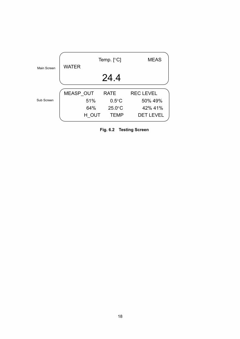
18
Temp. [°C] MEAS WATER
24.4
MEASP_OUT RATE REC LEVEL 51% 0.5°C 50% 49% 64% 25.0°C 42% 41% H_OUT TEMP DET LEVEL
Fig. 6.2 Testing Screen
Main Screen
Sub Screen

19
5.5 Test End ! Warning: The bath liquid and heating bath (beaker) are hot after
a test. To avoid burns, do not touch any part with bare hands except for the handle.
5.5.1 Normal end When the softening points of the left or right samples is detected, the buzzer sounds
intermittently for 8 seconds, and then the softening point of the other side sample is
detected, the buzzer sounds intermittently for 8 seconds again to indicate the end of the
test.
At the same time, the heater stops heating and the cooling fan starts cooling (COOL lamp
lit). The cooling time is fixed at 10 minutes. (The cooling fan is for cooling the heater, not for
the bath liquid.)
The test result is displayed flashing as shown in Fig.7 and held until the RESET key is
pressed.
S.P °C LEFT
RIGHT
S.P [°C]
LEFT SAMPL1 50.6 RIGHT SAMPL2 AVE
Fig.7 Test End (Normal) Screen
Up to 20 test results are stored automatically.
To display past test results, press the MODE and RESET keys at the same time and
then release the RESET key to display the results screen.
To display a specific past test result, move the flashing cursor to "Select" using the
right/left keys. Change the number at the upper left of the screen using the up/down
keys to select desired data.
For further details, refer to the Maintenance Manual.
Main Screen
Sub Screen
50.6 50.8
50.8
50.7

20
5.5.2 Abnormal Termination (1) If the sample temperature has reached the safety stop temperature (6) or the upper
limit of the measuring range before the other side is detected after one-side detection, the overheat prevention function is activated to stop the heater and start the cooling fan (COOL lamp lit). The buzzer sounds intermittently for 8 seconds. The test result is then displayed flashing, as shown in Fig. 8, and held until the RESET switch is pressed.
S.P °C LEFT
RIGHT
S.P [°C] LEFT SAMPL1 50.6 RIGHT SAMPL2 0.0 AVE 50.6
Fig. 8 Test End Screen: Abnormal(1)
Note(6): By default, tests stop at the one-ended detection temperature +10°C (about 2 min later). When measuring samples having very different softening points simultaneously, however, this value needs to be changed. For details on how to change, refer to the Maintenance Manual. (2) If the sample temperature has reached the upper limit before either side is
detected, the overheat prevention function is activated to stop the heater and start the cooling fan (COOL lamp lit). The buzzer sounds intermittently for 8 seconds. The screen shown in Fig.9 is displayed and held until the RESET switch is pressed.
TROUBLE S.P > 80.0 Temp. [°C] 80.5
Sub Screen None
Fig.9 Test End Screen: Abnormal(2)
5.6 Removing the Temperature Sensor Before removing the ring holder and bottom plate assembly at the end of a test, be sure to return the temperature sensor to the temperature sensor holder.
Main Screen
Sub Screen
50.6
Main Screen

21
6 Data Storage Functionality
This instrument has the capacity to automatically store the results of the last 20 tests.
To access the results history, press and release the RESET key while holding down the
MODE key. The Test History Screen in Fig.10 is displayed.
The most recent test results are always shown as data no.00, with id numbers increasing
with age. Data recorded more than 20 test runs ago is discarded. Result sets can be
scrolled through by pressing the up and down arrow keys.
Fig. 10: Test History Screen
If the optional clock board is not installed, the date and time fields will all show 01/01
01:01.
The sample name field always shows a value, even when sample name input is disabled.
(In this case AAAAAA will typically be displayed, as it is the default value).
Data No.
(00-19)
Test Date
(Month/Day)
Test Time
(Hour: Min, Sec)
Sample ID Softening Point
No [00]
Up or
Down key
Most Recent Data
Oldest Data
ID AAAAAA SP.R 46.7oC ID AAAAAA SP.L 45.6oC
07 09/13 15:28 12
ID ST0856 SP.R 61.4 oC ID ST0857 SP.L 62.3oC
07 08/10 13:42 53 No [19]

22
7 Parts Replacement and Self-inspection
! Caution: For consumables, accessories, and other replacement parts, use only genuine Tanaka parts.
7.1 Consumables and Spares When placing an order for consumables or spares of this tester, add "For ASP-5" before
the name of a part given in Table 2 and state the necessary quantity correctly.
For the parts replacement method, refer to the Maintenance Manual.
Table 2 Consumables and Spares for Model ASP-5
Heater Coil (1 kW @100V or 1 kW @220V)
Insulator set (100/120V or 220/240V)
Projection Lamp (H-0937)
Light Receiver Assembly
Temperature Sensor (with metal connector)
Shouldered Ring
Ball 3/8in.
Ball Centering Guide
Ring Holder and Bottom Plate Assembly
Bath (beaker)
Handle for Beaker
7.2 Periodic Inspection and Adjustment This instrument has been shipped after inspection for immediate use after delivery.
However, temperature corrections need to be made periodically.
The correction method is as follows:
(1) Install a ring holder in the filled bath and insert the temperature sensor and reference
thermometer (ASTM 15C for water, ASTM 16C for glycerin) into the temperature
sensor mounting hole and the adjacent hole. Secure the thermometer appropriately
so that the lower edges of the temperature sensor and thermometer become level.
(2) Select a test mode. While heating the sample, compare the temperature sensor
value and the thermometer reading in each mode. If any deviations are found, make
the appropriate temperature corrections. For the temperature correction procedure,
refer to the Maintenance Manual.

23
8 Troubleshooting (Self-diagnosis Function) If any faults occur, the tester produces a buzzing sound and displays the messages given
in Table 3.
If any of these problems occur, all power is switched OFF.
For troubleshooting procedures, refer to the Maintenance Manual Table 3 Error Messages
Error Display Buzzer Control computer runaway No display Continuous sounding Projector Lamp faulty PHOTO SENSOR LAMP 8-second intermittent Left Receiver Assy faulty PHOTO SENSOR LEFT 8-second intermittent Right Receiver Assy faulty PHOTO SENSOR RIGHT 8-second intermittent Temperature Sensor open circuit TEMPSENSOR 8-second intermittent Temperature Sensor is not set (7) SENSOR POSITION 8-second intermittent Internal Battery out (8) REPLACE BATTERY 8-second intermittent Note(7): If the temperature does not show a certain rise in a specified time after the start of
a test, this message is displayed to indicate that the temperature sensor is not at the
specified position. If this is attributable to a heater open circuit or any other mechanical fault,
the same phenomenon occurs even when the temperature sensor is set. Note(8): This phenomenon appears only at power-on and is cleared when the RESET key
is pressed once. If this message is displayed frequently, however, be sure to check the
settings because various settings may have been lost. In preparation for this situation,
record the instrument settings on the setting table given in the Maintenance Manual.
! Caution: If you feel that the tester is behaving even slightly abnormally, stop using the tester and check it. If you are unsure about the source of the abnormality, contact Tanaka.

24
9 After-sales Service To order consumables or parts, or to request service, contact Tanaka or an authorized
distributor. Parts necessary for maintaining/repairing this tester are kept in inventory for a
minimum of 5 years after the delivery of the tester. 10 If This Manual is Lost The Instruction Manual and the Maintenance Manual are parts of this instrument. If a
manual is lost, a request for a new copy can be made to Tanaka or an authorized
distributor.
It is also highly recommended that the address and telephone number of Tanaka and/or an
authorized distributor are kept separately from this manual.
11 Transferring the Tester When transferring this tester to a third party, inform Tanaka or an authorized distributor.
Incorrect source voltage could result in damage or malfunctions.
Be sure to transfer the Instruction Manual (this manual) and Maintenance Manual with the
tester. 12 Disposing of the Tester This instrument does not contain any hazardous materials. Dispose of the instrument as general industrial waste.

25
13 Specifications (1) Conforming standards: "Test Method for Softening Point of Bitumen (Ring-and-Ball
Apparatus)" in ASTM D36, etc
(2) Type: Two Rings & Two-Balls type
(3) Measuring range: Ambient to 200°C (392°F)
(4) Display: Fluorescent display (VFD module) 240×64 dots (Accuracy: 0.1°C)
(5) Temperature sensor: Platinum resistance probe (PT100) in stainless steel sheath
(6) Sequence control system: By on-board microcomputer
(7) Heater: Nichrome-coil heater (1 kW @100 V or 1 kW @220V)
(8) Cooling system: Forced air cooling with a propeller fan
(9) Softening point detection system: Photoelectric detection
Light projection: Incandescent lamp Light detection: Photodiode
(10) Heating bath liquid: Room temperature to 80°C: Distilled water 80 to 200°C: Glycerin
(11) Safety mechanism: Overheat prevention and self-diagnosis functions Overheat prevention function: Terminates a test forcibly in the following cases.
Other side not detected within the set range after one-sided detection
No detection even at the upper limit of the measuring range
Self-diagnosis function: Turns all output OFF in the following cases. Control computer runaway Light projection or detection circuit failure Temperature sensor open circuit No specified temperature increase within the set
time after the start of a test (12) Data output: RS-232C one channel (for PC or optional printer) (13) Power supply: 100, 120, 220 or 240 VAC (factory set), 50/60 Hz, 1.7kW (max,
@120V) (14) Dimensions and weight: Control unit: W230 × D455 × H110 mm, about 6 kg
(excluding projections) Test unit: W230 × D375 × H270 mm, about 7 kg
(excluding projections) (15) Minimum installation space: W350 × D600 × H550 mm (Test unit on the control unit) (16) Standard Accessories:
Ring Holder and Bottom Plate Assembly 1 pc Shouldered Ring 6 sets Ball 3/8in. 6 pcs

26
Ball Centering Guide 2 pcs Bath (beaker) with Handle 1 pc Temperature sensor (75-cm lead with metal connector) 1 pc Temperature sensor holder (made of polypropylene) 1 pc Power cord with 3P plug (3 m with ground) 1 pc Power Connecting Cable (0.6 m) 1 pc Signal Connecting Cable (0.6 m) 1 pc Instruction Manual 1 copy Maintenance Manual 1 copy
(17) Optional Accessories: (Sold separately)
・ Power Connecting Cable, 3m
・ Signal Connecting Cable, 3m
・ Built-in Clock Board (used for data storage function and optional printer)
・ Printer:(necessary for recording test results automatically) Model : BS2-80TS (Serial dot-matrix printer made by Sanei
Electric)
Printing system: Thermal serial dot-matrix printing
Paper size: 80W mm
Weight: 450 g (Main unit only)
Dimensions: 134(W) x 60(H) x 180(D)mm w/o AC adapter, paper roll,
batteries
Power supply: AC adapter or dry battery (AA size) × 4

27
Product Warranty
1. This product has passed a quality assurance inspection to the standards of Tanaka
Scientific Limited.
2. This product will be warranted for a period of one year from the date of delivery.
To avoid later confusion, be sure to enter the date of delivery in warranty ticket below.
3. If any faults occur due to normal use within the warranty, the product will be repaired
free of charge.
4. Be sure to notify Tanaka Scientific Limited when repairs being requested are covered
under the warranty.
5. The following faults or damage are not covered by the warranty:
・ Any fault or damage arising from failure to adhere to all warnings and
precaution as described in the instruction manual
・ Any fault or damage arising from misuse or carelessness
・ Any fault or damage arising from repairs or alterations unauthorized
by Tanaka Scientific Limited
・ Any fault or damage arising from falls or accidents during
transportation after the initial delivery
・ Any fault or damage arising from external causes, such as fire, act of
God (earthquake, storm, or flood), environmental contamination, or
power supply variations
6. All other repairs, Glassware, Heater Coil, Temperature Sensor, Lump, consumables
and accessories are chargeable.
Product Name Automated Softening Point Tester
Control unit No. Model Name ASP-5 Serial No.
Test unit No.
Warranty Period One year from the date of delivery:
Manufactured and sold by: Tanaka Scientific Limited
Contact: 7-10-3, Ayase, Adachi-ku, Tokyo 120-0005 T E L :+81-3-3620-1711 F A X :+81-3-3620-1713 E - m a i l :[email protected]
Distributor:

28