automated test system for nif flashlamps … test system for nif flashlamps* tim da silva, pat...
TRANSCRIPT

AUTOMATED TEST SYSTEM FOR NIF FLASHLAMPS* Tim da Silva, Pat Creely, Jud Hammon, Ron Shaw
Titan Corporation, Pulse Sciences Division+ 2700 Merced St., San Leandro, CA 94577
Robert T. Boyle, Jr, E. Stephen Fulkerson Lawrence Livermore National Laboratory
7000 East Ave., Livermore, CA 94551
* This work was performed under the U.S Department of Energy by the Lawrence Livermore National Laboratory under contract W-7405-Eng-48. + The Titan Corporation acquired the pulsed power portion of Maxwell Physics International Company in March, 2001, after the completion of the project described in this paper.
Abstract This paper describes design and operation of the flashlamp test system, used to evaluate the primary laser flashlamps on the National Ignition Facility (NIF) at the Lawrence Livermore National Laboratory (LLNL) in Livermore, California. The tester delivers repetitive high voltage pulses to a series pair of flashlamps at levels closely simulating those encountered in normal operation. Each lamp pair is subjected to a pre-ionization and main pulse shot sequence, with two minute intervals between shots. This capability allows the manufacturer to test and evaluate the flashlamps for infant mortality and longevity before delivery to NIF [1]. All operations are under computer control with fully automated test and data acquisition capabilities requiring minimal operator input. The system is designed to operate continuously. Typical pre-ionization and main pulse outputs are Pre-ionization Pulse: Vchg=27kV, Ipeak=3kA, E=2.4kJ, Pulse Width: (10% -90%)=200us Main Pulse: Vchg=23kV, Ipeak=24kA, E=78.6kJ, Pulse Width: (10% -90%)=350us
I. INTRODUCTION Maxwell Physics International+, working with the LLNL staff, have designed and installed a flashlamp test system in the PerkinElmer Optoelectronics facility in Salem MA.[2]. The system provides test modes for infant mortality, longevity and trigger checkout of production lamps for NIF. The test kit provides an easy, relatively fast way to verify lamp operation / integrity under simulated NIF electrical operating conditions. The system block diagram is shown in Figure 1.
Figure 1. System Block Diagram
II. SYSTEM DESCRIPTION The test kit is composed of five main subsystems. A pulsed power cabinet, remote control console, low conductivity de-ionized water conditioning system, flashlamp cabinet with lamp cassette loading cart and facility interlocks system. The pulsed power cabinet is show in Figure 2.
Figure2. Pulsed Power Enclosure Photo © Maxwell
The Pulsed Power Cabinet houses the high voltage components that generate the flashlamp current pulses. These include the high voltage power supplies, trigger generators, capacitors, ignitrons, inductors, safety switches, and other support components. The cabinet is constructed of heavy-gage steel with dimensions of approximately 5’ high by 6’ long by 4’deep. Two doors along one side provide access to the interior, which is continuously lighted by overhead fluorescent lamps. Castors provide mobility. See Figure 3 for cabinet internals. The pulsed power system consists of two sets of switched capacitor circuits driving a common load through a pulse forming inductor. Ignitrons are used as the switching devices with both circuits having two in series. This virtually eliminates pre-fires while increasing voltage hold off. Two pneumatic actuators serve as an output shorting switch and a flashlamp selector
0-7803-7120-8/02/$17.00 © 2002 IEEE

Report Documentation Page Form ApprovedOMB No. 0704-0188
Public reporting burden for the collection of information is estimated to average 1 hour per response, including the time for reviewing instructions, searching existing data sources, gathering andmaintaining the data needed, and completing and reviewing the collection of information. Send comments regarding this burden estimate or any other aspect of this collection of information,including suggestions for reducing this burden, to Washington Headquarters Services, Directorate for Information Operations and Reports, 1215 Jefferson Davis Highway, Suite 1204, ArlingtonVA 22202-4302. Respondents should be aware that notwithstanding any other provision of law, no person shall be subject to a penalty for failing to comply with a collection of information if itdoes not display a currently valid OMB control number.
1. REPORT DATE JUN 2001
2. REPORT TYPE N/A
3. DATES COVERED -
4. TITLE AND SUBTITLE Automated Test System For Nif Flashlamps
5a. CONTRACT NUMBER
5b. GRANT NUMBER
5c. PROGRAM ELEMENT NUMBER
6. AUTHOR(S) 5d. PROJECT NUMBER
5e. TASK NUMBER
5f. WORK UNIT NUMBER
7. PERFORMING ORGANIZATION NAME(S) AND ADDRESS(ES) Titan Corporation, Pulse Sciences Division+ 2700 Merced St., SanLeandro, CA 94577
8. PERFORMING ORGANIZATIONREPORT NUMBER
9. SPONSORING/MONITORING AGENCY NAME(S) AND ADDRESS(ES) 10. SPONSOR/MONITOR’S ACRONYM(S)
11. SPONSOR/MONITOR’S REPORT NUMBER(S)
12. DISTRIBUTION/AVAILABILITY STATEMENT Approved for public release, distribution unlimited
13. SUPPLEMENTARY NOTES See also ADM002371. 2013 IEEE Pulsed Power Conference, Digest of Technical Papers 1976-2013, andAbstracts of the 2013 IEEE International Conference on Plasma Science. IEEE International Pulsed PowerConference (19th). Held in San Francisco, CA on 16-21 June 2013. U.S. Government or Federal PurposeRights License.
14. ABSTRACT This paper describes design and operation of the flashlamp test system, used to evaluate the primary laserflashlamps on the National Ignition Facility (NIF) at the Lawrence Livermore National Laboratory(LLNL) in Livermore, California. The tester delivers repetitive high voltage pulses to a series pair offlashlamps at levels closely simulating those encountered in normal operation. Each lamp pair is subjectedto a pre-ionization and main pulse shot sequence, with two minute intervals between shots. This capabilityallows the manufacturer to test and evaluate the flashlamps for infant mortality and longevity beforedelivery to NIF [1]. All operations are under computer control with fully automated test and dataacquisition capabilities requiring minimal operator input. The system is designed to operate continuously.Typical pre-ionization and main pulse outputs are Pre-ionization Pulse: Vchg=27kV, Ipeak=3kA, E=2.4kJ,Pulse Width: (10% -90%)=200us Main Pulse: Vchg=23kV, Ipeak=24kA, E=78.6kJ, Pulse Width: (10% -90%)=350us
15. SUBJECT TERMS
16. SECURITY CLASSIFICATION OF: 17. LIMITATION OF ABSTRACT
SAR
18. NUMBEROF PAGES
4
19a. NAME OFRESPONSIBLE PERSON
a. REPORT unclassified
b. ABSTRACT unclassified
c. THIS PAGE unclassified

Standard Form 298 (Rev. 8-98) Prescribed by ANSI Std Z39-18

respectively. See Figure 4 for pulsed power circuit block diagram.
Figure 3. Pulsed Power Enclosure Internals
Figure 4. Pulsed Power Circuit Block Diagram
The main energy storage capacitor consists 4 each, 300µF/25kV capacitors in a connected in a series/parallel configuration. This configuration yields a total capacitance of 300µF and a voltage rating of 50kV. At 35kV charge voltage, the total stored energy is ≈184 kJ. This was done to utilize existing NIF capacitors while yielding high reliability and long capacitor life. The PILC capacitor is rated 6.5µF at 35kV maximum charge voltage, with 80% maximum reversal, 20% typical The maximum stored energy is 4 kJ. The capacitor was tested at 40KV for 60s. The main and PILC capacitors are charged by a 35kV, 8kJ/s & 350J/s high voltage power supplies respectively. The power supplies have short circuit and overvoltage protection for the output. The PILC and main discharge circuits use different ignitrons due to the different current requirements. The PILC ignitrons (Richardson P/N NL7703LP) are rated at 20kV anode voltage with peak discharge currents of 100kA. The main ignitrons (Richardson P/N NL8900) are rated at 25kV anode voltage with peak discharge currents of 350kA. Ignitrons require differential heating and cooling for reliable high voltage standoff and trigger operation Anode heating is provided by two 10W resistors mounted in copper blocks attached to each ignitrons anode. The resistors are heated by 6.7Vac source, supplied by an
isolation transformer. Four isolation transformers supply power to each of the ignitron anode heaters in the cabinet. Cathode cooling is provided by chilled, deionized water circulating through a water jacket surrounding the cathode. The deionized water has sufficiently high resistance to provide voltage insulation between ignitrons when charged. The water is cooled and deionized by the Water Conditioning Cabinet. See Figure 5
Figure 5. Water Processing Cart
Two trigger generators provide the high voltage pulses required to trigger the ignitron igniters. Each trigger generator consists of a 5µF capacitor, an SCR, a diode, and a dual-secondary pulse transformer. The two transformer secondary windings are connected to the igniters on each of the two, series-connected ignitrons. A 10Ω resistor and diodes in each secondary circuit limits secondary currents and prevents voltage reversals on the igniters. In operation, the capacitors in each trigger generator are simultaneously charged to 1200Vdc from the Control Box. A 5V-trigger pulse from the Control Box triggers the SCR, which discharges the capacitor into the pulse transformer primary winding. Each secondary produces a 2400V pulse (open circuit) which is sufficient to break down the igniter and trigger the ignitrons into conduction. The trigger pulsewidth is ≈8µs in duration. See Figure 6.
Figure 6. D Size Ignitron / Trigger System
Residual stored energy on the high voltage capacitors is safely discharged by crowbar relays. The relays are controlled by interlock status as well as digital commands

from the control computer. All interlocks must be closed before the crowbar relays may be operated (i.e. opened). Two crowbar relays are used on the main capacitors, one across the upper parallel set and one across the lower parallel set. One crowbar relay is connected across the PILC capacitor. Resistors in series with each crowbar contact, limit the discharge current to within rated contact current levels. See Figure 7.
Figure 7. Main Capacitor Crowbar Relay System
Two pneumatic switches inside the cabinet are used for flashlamp test selection and pulsed power output shorting. The switch actuators are driven by compressed air from solenoid valves operated by the control system. The position status of both switches is monitored by the computer and may be viewed through a window on the right-front door of the Pulsed Power Cabinet. Clear acrylic windows with labels are located on top of each pneumatic switch. This allows the operator to visually check that the pulsed power output circuit is safely shorted before opening the Flashlamp Cabinet doors. See Figure 8.
Figure 8 Flashlamp Cabinet
Charge voltage monitors and output pulse diagnostics are included in the pulse power system. Redundant resistive voltage divider networks are provided for the main and PILC capacitors. One set of dividers supplies DC charge data to the control system while the other set drives two analog meters mounted on the left-hand cabinet Voltage and current monitors provide output voltage and current pulse diagnostics. These monitors may be connected to a Tektronix model 3012 oscilloscope mounted in the Control Box on the side of the Pulsed Power Cabinet. Normally, the output current monitor is connected to channel 1 of the oscilloscope. The control computer acquires output current waveform data from the oscilloscope through a GPIB fiber optic link. The data is analyzed on each shot to determine if the flashlamp set has passed or failed the test. A Chi square analysis is used for this test. Chi square analysis is a mathematical process of determining the difference in amplitude and waveshape of two waveforms. The upper portion of the test waveform pulse is found (in this case, all points above 20% of peak) and compared against the equivalent data of the reference waveform. A point by point calculation is made in which the difference is found through subtraction, then squared. The squares are summed and then the square root is calculated. The result is a percentage error deviation, which is compared against the previously established tolerances. Deviations outside of tolerance are considered a failure. Figure 9 shows a plot taken by the test system overlaying the reference & acquired waveform used for the Chi square test. In this figure both the waveforms overlay well and would pass the Chi square test.
Figure 9. Flashlamp Output Current Pulse Overlay with Reference Waveform for 23.5% Explosion Fraction Shot
(Shows PILC and Main Current Pulses)
III Software Control System
The control software was custom designed using LabView, a graphical programming language created by National Instruments. The software has three principal
screens from which the system is operated, the Flashlamp Test Setup panel, the Lifetest Operations panel and the Trigger Test panel. A typical operational sequence is described below. The desired flashlamp pair is installed in the flashlamp cabinet side selected for testing. All AC power is turned on to the system. The system is setup using the test setup panel which allows the operator to select the flashlamp pair to be tested as well as the energy level , flashlamp explosion fraction, to be discharged through the lamp pair. The lifetest panel is selected and brought up. The interlocks for the system are checked and verified on this panel. The start button is pushed and the system then automatically performs the charge / fire sequence until the multiple shot run is completed successfully or aborted due to a fault. During the automated sequence the following operations are done. The output-shorting switch is opened, connecting the pulsed power circuit to the selected flashlamp set. The PILC and main high voltage power supplies are turned on, charging the capacitors to a maximum of 35kV. When the capacitor are fully charged, the trigger generator is triggered, causing the PILC ignitrons to switches to close, discharging the PILC capacitor into the flashlamps. At the appropriate time interval, the main circuit is triggered in a similar manner, which discharges the Main capacitors into the flashlamps. The Test Setup panel appears when the control software is started. The panel includes all controls for entering the shot parameters, selecting a test type, viewing previous shot waveforms, and checking the shotlog. See Figure 10.
Figure 10. Flashlamp Test Setup Panel
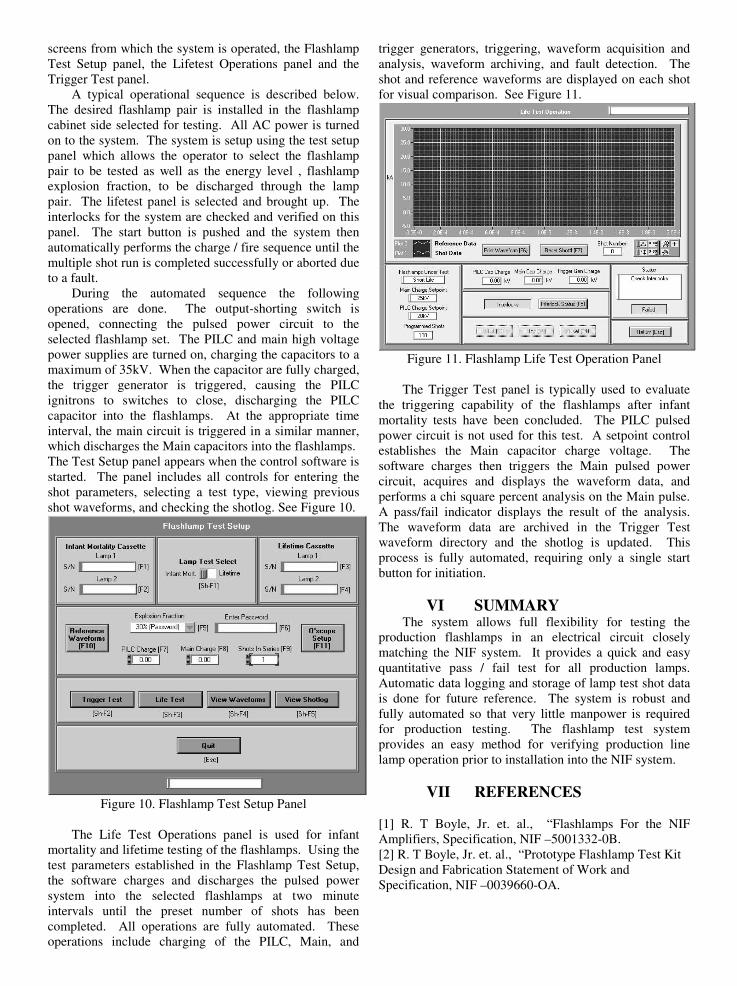
The Life Test Operations panel is used for infant mortality and lifetime testing of the flashlamps. Using the test parameters established in the Flashlamp Test Setup, the software charges and discharges the pulsed power system into the selected flashlamps at two minute intervals until the preset number of shots has been completed. All operations are fully automated. These operations include charging of the PILC, Main, and
trigger generators, triggering, waveform acquisition and analysis, waveform archiving, and fault detection. The shot and reference waveforms are displayed on each shot for visual comparison. See Figure 11.
Figure 11. Flashlamp Life Test Operation Panel
The Trigger Test panel is typically used to evaluate the triggering capability of the flashlamps after infant mortality tests have been concluded. The PILC pulsed power circuit is not used for this test. A setpoint control establishes the Main capacitor charge voltage. The software charges then triggers the Main pulsed power circuit, acquires and displays the waveform data, and performs a chi square percent analysis on the Main pulse. A pass/fail indicator displays the result of the analysis. The waveform data are archived in the Trigger Test waveform directory and the shotlog is updated. This process is fully automated, requiring only a single start button for initiation.
VI SUMMARY The system allows full flexibility for testing the production flashlamps in an electrical circuit closely matching the NIF system. It provides a quick and easy quantitative pass / fail test for all production lamps. Automatic data logging and storage of lamp test shot data is done for future reference. The system is robust and fully automated so that very little manpower is required for production testing. The flashlamp test system provides an easy method for verifying production line lamp operation prior to installation into the NIF system.
VII REFERENCES [1] R. T Boyle, Jr. et. al., “Flashlamps For the NIF Amplifiers, Specification, NIF –5001332-0B. [2] R. T Boyle, Jr. et. al., “Prototype Flashlamp Test Kit Design and Fabrication Statement of Work and Specification, NIF –0039660-OA.