automatic dem extraction - pci geomatics · autodem2 - generates a digital elevation model from...
TRANSCRIPT
Page | 1 The information in this document is subject to change without notice and should not be construed as a commitment by PCI Geomatics.
PCI Geomatics assumes no responsibility for any errors that may appear in this document.
Technical Specifications
Automatic DEM Extraction
The Automatic DEM Extraction module allows you to create Digital Elevation Models (DEMs) from stereo
airphotos, stereo images and RADAR data. Image correlation is used to extract matching pixels in two
overlapping images and then use the sensor geometry from a computed math model to calculate x, y, and z
positions. Automatic DEM extraction allows you to batch epipolar generation, batch the DEM extraction
process, geocode DEMs, and create absolute or relative DEMs.
PCI MODULE PREREQUISITES OrthoEngine Automatic DEM Extraction requires Geomatica Core or Geomatica Prime, plus one of the
associated sensor suites (Air Photo Ortho, Satellite Ortho, or Radar Ortho).
SUPPORTED SENSORS The Automatic DEM Extraction module supports the following airphoto, satellite and RADAR sensor types.
Airphoto Sensors
All digital and video frame images
All scanned standard aerial images
Satellite Sensors In general terms, DEM extraction should work for any satellite sensor that produces stereo data. The
following list are known sensors that have been tested:
ALOS (PRISM)
ASTER
CARTOSAT
EROS
GEOEYE
IKONOS
ORBVIEW
PLEIADES
QUICKBIRD
SPOT 1-6
TH-01
WORLDVIEW ½
ZY-3
RADAR Sensors
RADARSAT 1/2
ASAR
Page | 2 The information in this document is subject to change without notice and should not be construed as a commitment by PCI Geomatics.
PCI Geomatics assumes no responsibility for any errors that may appear in this document.
Technical Specifications
EPIPOLAR PAIRS Epipolar pairs increase the correlation process speed and reduce the possibility of incorrect matches.
Stereo pairs are reprojected, ensuring that the left and right images have a common orientation, and
matching features between the images appear along a common x-axis. Using epipolar pairs, you can:
Choose from the following pairs:
o User Select – selects a pair manually
o Maximum Overlapping Pairs – selects the pair with the highest amount of overlap
o Minimum Percentage Overlap – specifies the lowest percentage of acceptable
overlap
o All Overlapping Pairs – selects all pairs that overlap above a minimum percentage
Limit the amount of memory used to generate epipolar pairs
Define a Down-sample factor to reduce an epipolar image resolution
Define a Down-sample filter
Set up epipolar-pair start times
DEM EXTRACTION Using DEM extraction, you can:
Specify the minimum and maximum elevation to estimate a search-area correlation
Specify a failure value to represent any failed (uncorrelated) pixel values in the resulting
DEM
Specify a background value to represent any ‘no-data’ pixel values
Set the DEM detail to high, medium, or low for the needed level of detail
Select an output DEM channel type to 16-bit signed or 32-bit real
Specify a pixel sampling interval for the number of image pixels and lines used to extract
one DEM pixel
Use a clip region to process a specific area only
Fill holes and filter interpolated failed values and filter elevation values automatically
Create a score channel to represent the correlation score for each DEM pixel
Delete an epipolar pair after use
Create a Geocoded DEM by using geocoding stored in the project
Set up DEM extraction start times
DEM EDITING Digital elevation models (DEMs) may contain pixels with failed or incorrect values. You can edit a DEM to
smooth out irregularities and create a more accurate model, and in turn, generate more accurate
orthorectified images. For example, areas such as lakes often contain misleading elevation values; setting
those areas to a constant value improves the model that will produce a more accurate representation of
the lake in the ortho image.
Using the Focus DEM Editing window requires only a DEM; that is, a raster channel in a writable format. To
fully use all the functionality available in the DEM Editing window, however, and to produce the best
Page | 3 The information in this document is subject to change without notice and should not be construed as a commitment by PCI Geomatics.
PCI Geomatics assumes no responsibility for any errors that may appear in this document.
Technical Specifications
possible DEM, the DEM file should contain additional information. In particular, if the DEM file was
extracted from epipolar images, you can make use of that imagery to help with your editing.
DEM files created using PCI technology contain extra information that facilitates DEM editing, including a
cutline vector segment and file-level metadata.
The main toolbar on the DEM Editing window provides quick access to several functions that facilitate
working with the DEM.
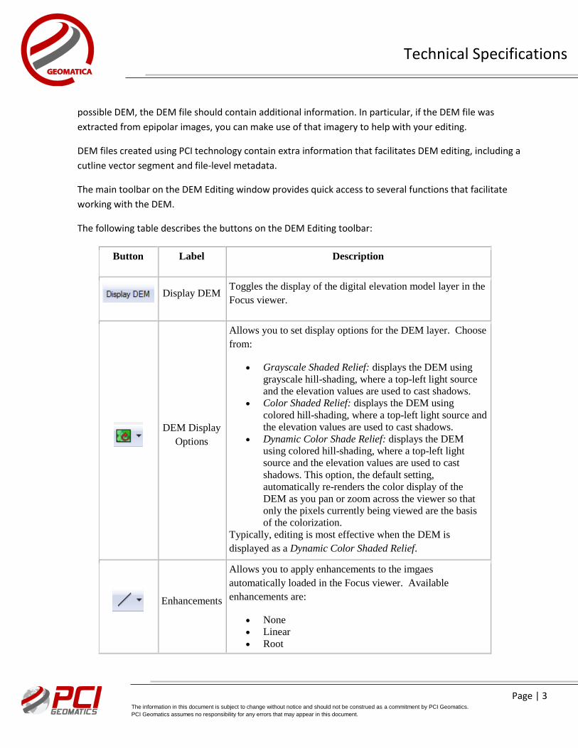
The following table describes the buttons on the DEM Editing toolbar:
Button Label Description
Display DEM
Toggles the display of the digital elevation model layer in the
Focus viewer.
DEM Display
Options
Allows you to set display options for the DEM layer. Choose
from:
Grayscale Shaded Relief: displays the DEM using
grayscale hill-shading, where a top-left light source
and the elevation values are used to cast shadows.
Color Shaded Relief: displays the DEM using
colored hill-shading, where a top-left light source and
the elevation values are used to cast shadows.
Dynamic Color Shade Relief: displays the DEM
using colored hill-shading, where a top-left light
source and the elevation values are used to cast
shadows. This option, the default setting,
automatically re-renders the color display of the
DEM as you pan or zoom across the viewer so that
only the pixels currently being viewed are the basis
of the colorization.
Typically, editing is most effective when the DEM is
displayed as a Dynamic Color Shaded Relief.
Enhancements
Allows you to apply enhancements to the imgaes
automatically loaded in the Focus viewer. Available
enhancements are:
None
Linear
Root
Page | 4 The information in this document is subject to change without notice and should not be construed as a commitment by PCI Geomatics.
PCI Geomatics assumes no responsibility for any errors that may appear in this document.
Technical Specifications
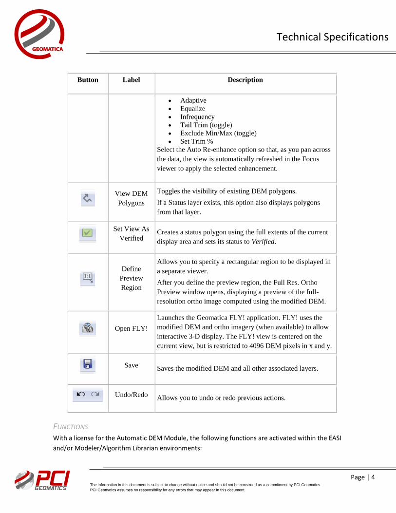
Button Label Description
Adaptive
Equalize
Infrequency
Tail Trim (toggle)
Exclude Min/Max (toggle)
Set Trim %
Select the Auto Re-enhance option so that, as you pan across
the data, the view is automatically refreshed in the Focus
viewer to apply the selected enhancement.
View DEM
Polygons
Toggles the visibility of existing DEM polygons.
If a Status layer exists, this option also displays polygons
from that layer.
Set View As
Verified Creates a status polygon using the full extents of the current
display area and sets its status to Verified.
Define
Preview
Region
Allows you to specify a rectangular region to be displayed in
a separate viewer.
After you define the preview region, the Full Res. Ortho
Preview window opens, displaying a preview of the full-
resolution ortho image computed using the modified DEM.
Open FLY!
Launches the Geomatica FLY! application. FLY! uses the
modified DEM and ortho imagery (when available) to allow
interactive 3-D display. The FLY! view is centered on the
current view, but is restricted to 4096 DEM pixels in x and y.
Save Saves the modified DEM and all other associated layers.
Undo/Redo Allows you to undo or redo previous actions.
FUNCTIONS
With a license for the Automatic DEM Module, the following functions are activated within the EASI
and/or Modeler/Algorithm Librarian environments:
Page | 5 The information in this document is subject to change without notice and should not be construed as a commitment by PCI Geomatics.
PCI Geomatics assumes no responsibility for any errors that may appear in this document.
Technical Specifications
AUTODEM - Generates a digital elevation model from stereo images
AUTODEM2 - Generates a digital elevation model from stereo images – OpenMP enabled
DSM2DTM – Convert a DSM to DTM
ELEVRMS - Reads elevations from a digital elevation channel and compares the elevations
with elevation values from a given GCP (ground control point) segment or from a vector
segment
EPIPOLAR2 - Generates epipolar images from stereo pairs or raw images – OpenMP
enabled
GEOCODEDEM - geocodes epipolar digital elevation models by reprojecting to the ground
coordinate system
GEOCODEDEM2 - geocodes epipolar digital elevation models by reprojecting to the ground
coordinate system – OpenMP enabled VDEMINGEST – Ingest vector files for interpolation to a DEM VDEMSETUP – Setup output DEM file for vector interpolation workflow
.
For more information, contact
PCI Geomatics
50 West Wilmot Street
Richmond Hill, ON L4B 1M5
Canada
Phone: 1 905 764 0614
Fax: 1 905 764 9604
Email: [email protected]
Web: www.pcigeomatics.com