automatic door systems – this is record!
TRANSCRIPT

User manual record K 31 / K 41 V + Hautomatic door systems – this is record!
reco
rd.g
roup
record your global partner for entrance solutions
your global partner for entrance solutions

Table of contents
6454245 V4.1 2/ 61
Table of contents
1 General information ............................................................................................ 6
1.1 Purpose and use of these operating instructions ............................................................. 6
1.2 Copyright .......................................................................................................................... 6
1.3 Manufacturer BLASI GmbH ............................................................................................. 6
1.4 Product identification ........................................................................................................ 6
1.5 Description of door types ................................................................................................. 7
1.6 State of technology .......................................................................................................... 7
1.7 Door components ............................................................................................................. 7
2 Safety instructions and regulations ..................................................................... 8
2.1 Intended purpose of use ................................................................................................. 8
2.2 Presentation of warning signs .......................................................................................... 9
2.3 Fire load .......................................................................................................................... 10
2.4 Spare parts / liability ........................................................................................................ 10
2.5 Residual risks ................................................................................................................... 10
2.6 Notice power shutdown .................................................................................................... 10
2.7 Battery emergency power supply..................................................................................... 10
2.8 General safety and accident prevention regulations ........................................................ 11
3 Graphical display K31 / K41 ............................................................................... 12
4 Main mechanical components K31 / K41............................................................ 14
5 Specifications ..................................................................................................... 15
5.1 Environmental conditions ................................................................................................. 15
5.2 Electrical specifications of the system H+V+ST+SU........................................................ 15
5.3 Electrical lighting specifications........................................................................................ 16
6 Safety features and control elements K31 / K41 ................................................. 17
6.1 Legend for safety equipment and control elements K31 / K41 ........................................ 19
7 Description of the door ....................................................................................... 20
7.1 Description of the full and/or semi-automatic door........................................................... 20
8 Operating the door ............................................................................................. 21

Table of contents
6454245 V4.1 3/ 61
8.1 Semi-automatic key-operated switch .............................................................................. 21
8.2 Fully automatic key-operated switch ............................................................................... 21
9 Normalizing and calibrating with the key-operated switch ................................... 22
9.1 Reset button ..................................................................................................................... 22
9.2 Initialization / Activation of the restart lock with the reset button (R) ................................ 22
9.3 Normalization – Cancel the restart lock with the key-operated switch ............................. 22
9.4 Calibrate - Position the turnstile with the reset button (R) ............................................... 22
10 System operating modes .................................................................................... 23
10.1 LOCKED operating mode “semi and fully automatic doors” ............................................ 23
10.2 MANUAL operating mode “semi and fully automatic doors” ............................................ 23
10.3 AUTOMATIC operating mode .......................................................................................... 24
10.4 CONTINUOUS operating mode “fully automatic doors”................................................... 24
11 Over current, blocking and heavy starting detection .......................................... 25
12 Function during power failure ............................................................................ 26
12.1 Function of the pivot wing holding magnets during a power failure ................................. 27
13 Function when power is restored........................................................................ 28
13.1 Function of the pivot wing holding magnets when power is restored ............................... 28
14 Safety features of the door ................................................................................. 29
14.1 Emergency stop button ................................................................................................... 29
14.2 Information on motion detectors....................................................................................... 29
14.3 Vertical safety sensors or light barriers drum edge.......................................................... 29
14.4 Information on safety strips .............................................................................................. 30
14.5 Horizontal and vertical safety strips ................................................................................ 30
15 Optional components ......................................................................................... 31
15.1 Electric lock ..................................................................................................................... 31
15.2 Turnstile bar-bolt lock ....................................................................................................... 3315.2.1 Turnstile bar-bolt lock with limit switch (option)................................................................ 33
15.3 Turnstile corner lock ......................................................................................................... 33
15.4 Lock mechanism status indicator and door position indicator.......................................... 33
15.5 Light switch ...................................................................................................................... 33
15.6 Key pivot contact ............................................................................................................. 34

Table of contents
6454245 V4.1 4/ 61
15.7 Disabled button ............................................................................................................... 34
15.8 Start button ....................................................................................................................... 35
15.9 Emergency open button (pivot wing)................................................................................ 35
15.10 Key emergency operation button ..................................................................................... 36
15.11 Forward sensors turnstile wing ........................................................................................ 36
15.12 Vertical sensors strips drum walking area........................................................................ 37
15.13 Vertical multifunctional sensors drum walking area ......................................................... 37
15.14 Horizontal-pivot wing hinge light barrier (stop)................................................................. 37
15.15 Air curtain control ............................................................................................................. 37
15.16 Foldable turnstile wings and/or foldable drum walls......................................................... 38
15.17 Pivot wing button K31 / K41 (break out)........................................................................... 39
16 Conduct during malfunctions .............................................................................. 40
16.1 Possible troubleshooting .................................................................................................. 40
17 Tips on troubleshooting ..................................................................................... 41
18 Overview of the door parameters ....................................................................... 42
19 IBS-System display (service) ............................................................................. 44
20 Normalizing and calibrating with the IBS system display..................................... 46
20.1 Initialization – activation of the restart lock when power returns ..................................... 46
20.2 Normalization - Cancel the restart lock ........................................................................... 46
20.3 Calibrate – turnstile positioning ........................................................................................ 46
21 Troubleshooting per IBS-Display ........................................................................ 47
22 Function and safety inspection ........................................................................... 51
22.1 General information .......................................................................................................... 51
22.2 Inspection and maintenance ........................................................................................... 51
22.3 Spare parts / liability ........................................................................................................ 51
22.4 Operator duties ................................................................................................................ 52
23 Visual and functional inspection ......................................................................... 53
23.1 Monthly inspection procedures ........................................................................................ 53
24 Night shield ........................................................................................................ 56
24.1 Manual night shield .......................................................................................................... 56

Table of contents
6454245 V4.1 5/ 61
24.2 Night shield – deadman function ...................................................................................... 57
24.3 Semi-automatic night shield ............................................................................................. 58
24.4 Fully automatic night shield .............................................................................................. 59
25 Cleaning and care .............................................................................................. 60
26 Dismantling and disposal .................................................................................... 61

General information 1
6454245 V4.1 6/ 61
General information
Purpose and use of these operating instructions This document was written for the operator of the door: Meaning, it is for the person responsible for the operation and technical maintenance of the door. These operating instructions explain the handling of the door. They also provide the basics for proper operation and instructions on procedures as well as maintenance for any malfunctions that may occur. This document may also be given in extracts, to individuals who are entrusted with the daily operation of the door. The operator of the door must read the operating instructions first in order to observe safety regulations and exercise the duties of the operator! It is recommended to keep this document accessible, within reach of the door.
Copyright The copyright of the instructions remain at: BLASI GmbH Mahlberg It is prohibited to reproduce, distribute or use the manuals for purpose of competition without the written authorization of BLASI GmbH. Violation of the here stated copyrights will be prosecuted and fined with compensation of damage. Subject can change without prior notice. Differences between product and manual are thereby possible.
Manufacturer BLASI GmbH
BLASI GmbH Automatic Door Systems
Carl-Benz-Str. 5-15
D-77972 Mahlberg
Germany
Telephone: +49 7822-893-0
Fax: +49 7822-893-119
Product identification The nameplate located on the door provides accurate identification of the product.
1 1.1
1.2
1.3
1.4

General information 1
6454245 V4.1 7/ 61
Description of door types This manual describes the following system types:
K31Z / K41Z-H Semi-automatic door with central drive
K31Z / K41Z-V Fully automatic door with central drive
K31A / K41A-V Fully automatic door with external drive
K31 / K41-SU Door with subfloor drive technology
State of technology This system was developed using state of the art technology and officially recognized technical safety regulations. The system, depending on its options and diameter, comply with the requirements of the Machine Guidelines 2006/42/EG as well as EN 16005 and DIN 18650 (D). Nevertheless, danger may arise if not used as intended.
IMPORTANT Installation, commissioning, inspection, maintenance and repair work may only be conducted by qualified, trained and authorized technicians. After commissioning or repair work, fill in the check list and give it to the customer for safe keeping. We recommend obtaining a service agreement.
Door components
NOTICE Depending on the features of the door, not all operating and safety components in this manual are individually described in graphic images. The graphic images are for guidance only and do not claim to be complete. For more detailed information, please refer to the separate technical drawings.
1.5
1.6
1.7

Safety instructions and regulations 2
6454245 V4.1 8/ 61
Safety instructions and regulations
Intended purpose of use The system is designed exclusively for use as a pedestrian passage. The installation may only occur in dry areas. If there are deviations then proper waterproofing and water drains will be required on-site. Any other application or use beyond this purpose is not considered to be an intended purpose. The manufacturer bears no liability for any resulting damage; the operator alone shall bear the associated risk. The intended purpose also includes observation of the operating conditions specified by the manufacturer, in addition to regular care, maintenance and repair. Interventions in or alterations to the automatic door performed by non-authorized maintenance technicians exclude the manufacturer's liability for consequential damages.
2 2.1

Safety instructions and regulations 2
6454245 V4.1 9/ 61
Presentation of warning signs Various symbols are used in this guide for easier understanding:
NOTICE Useful advice and information to ensure correct and efficient workflow of the system.
IMPORTANT Specific details which are essential for trouble-free operation of the system.
IMPORTANT Important details which must be read for proper function of the system.
CAUTION
Against a potential hazardous situation that can lead to minor personal injury and property damage.
WARNING
Against a latent hazardous situation that can lead to severe injuries or death and cause substantial property damage.
DANGER
Against an imminent hazardous situation that can lead to severe injury or death.
DANGER
Against an imminent or latent hazardous situation that could lead to electric shock and cause serious injury or death.
2.2

Safety instructions and regulations 2
6454245 V4.1 10/ 61
Fire load
IMPORTANT In case of fire load, the system leave(s) can be mechanically deformed to such an extent that they cannot be moved. If the system is not part of a fire or smoke protection installation, it must not meet any fire protection specifications such as fire resistance or smoke control. If it is part of a fire or smoke protection installation, all the necessary documents such as approvals and conformity declarations are enclosed.
DANGER
Blocked by a fire hazard! • Suffocation or burns
A fire detection system must be implemented.
Spare parts / liability Reliable and trouble free operation of the door is only guaranteed when using parts that were recommended by the manufacturer. The manufacturer declines any liability for damages resulting from unauthorized modifications to the door or the use of parts that are not permitted.
Residual risks The system was designed according to standard technology and regulations. Nevertheless, improper use could endanger user safety and some residual risks may not be avoided.
Notice power shutdown
NOTICE A trouble free operating door is only guaranteed with a continuous supply of power. Therefore, never disconnect the power supply!
If the main power supply is disconnected, the door control will have to be normalized first after switching the power back on. To do so, turn the key-operated switch from AUTOMATIC to LOCKED and back again. Now the door is operational again.
Battery emergency power supply The charge level of the integrated battery is permanently monitored. If a discharge is determined, the message [17] will be shown on the optional IBS-System display.
2.3
2.4
2.5
2.6
2.7

Safety instructions and regulations 2
6454245 V4.1 11/ 61
General safety and accident prevention regulations
IMPORTANT When motion detectors are used, it must be ensured that no moving objects like flags, plants etc. can move into the detection area of the motion detectors.
IMPORTANT To avoid malfunctions, the system must NOT be disconnected from the power overnight!
IMPORTANT If an error occurs that could endanger personal safety, the system must be shut down immediately. It can only be put back into operation when the error has been rectified in a technically correct manner and the danger has been eliminated.
IMPORTANT No safety devices (i.e. sensors, protective wings) may be removed or put out of service.
CAUTION
Operational malfunctions and danger of falling due to the accumulation of dirt under the floor mat • Operational shutdowns, bruising, fractures
The floor mat or the flooring must be level and firmly installed. Accumulation of dirt under the floor mat must be removed regularly.
CAUTION
Unexpected OPENING / CLOSING / ROTATION • Bruises and contusions from the door wings
No persons or objects are allowed in the opening area of the door. No safety devices (sensors) should be removed or disabled. Do not rush through a door that is already closing.
2.8

Graphical display K31 / K41 3
6454245 V4.1 12/ 61
Graphical display K31 / K41
K31-V/NMA with central drive K41-V/NMA with central drive
K31-V/NMA with external rotor drive K41-V/NMA with external rotor drive
3

Graphical display K31 / K41 3
6454245 V4.1 13/ 61
K31-V/SU/NMA K41-V/SU/NMA
Abbreviation Description
A Passage width B Floor ring height
G Passage height I Cladding height
J Total height Q Total diameter
T Exterior diameter U Interior diameter

Main mechanical components K31 / K41 4
6454245 V4.1 14/ 61
Main mechanical components K31 / K41
Description
a Drum wall Curved, fixed aluminum frame for supporting curved glass or paneling.
b Drum wall edge Fixed structure made of vertical frame profiling for accommodating control units.
c Rotation unit turnstile Rotating inner part of the revolving door.
d Display case Show case in the centre of the rotation unit.
4

Specifications 5
6454245 V4.1 15/ 61
Specifications
Environmental conditions
Temperature range From -15 to +50° C
Humidity range Up to 85% rel. humidity, not condensing
Electrical specifications of the system H+V+ST+SU
Mains voltage: 220-240 volt
Frequency: 50-60 Hz
Nominal power: See system nameplate
Mains fuse: 16A circuit breaker with tripping characteristic C or K
Power consumption: Max.: 300 VA
In addition, per slave control: approx.: 250 VA
Control voltage: 24V DC (extra low voltage)
Motor voltage: 58 V (pulsed)
Fuse in the control: T4A
Safety class: 1
Degree of protection: IP 20
Safety class for subfloor systems: 3
Degree of protection for subfloor systems: IP 54 (subfloor)
An additional external upstream RCD circuit breaker In = 30mA (FI circuit breaker) must be installed on subfloor systems provided by the customer.
5 5.1
5.2

Specifications 5
6454245 V4.1 16/ 61
Electrical lighting specifications
High power LED spots Low voltage halogen spots
Transformer power supply 230-240 V
Frequency 50-60 Hz
Transformer secondary voltage 105 VA
Capacity per lamp/bulb 5.6 W 20 W
Protection class/Insulation class 2 B
Transformer degree of protection IP 20
NOTICE The power connection must be installed by a licensed electrician. The power must be able to be shut off via a main switch or residual current circuit breaker (on-site).
5.3

Safety features and control elements K31 / K41 6
6454245 V4.1 17/ 61
Safety features and control elements K31 / K41
INTERIOR VIEW in the closed position
Possible operating element variations
Pillar inside Pillar outside Installation on-site
6

Safety features and control elements K31 / K41 6
6454245 V4.1 18/ 61
EXTERIOR EXTERIOR
INTERIOR INTERIOR
Position of the turnstile wings in the locked position:
Turnstile wing K31 K41
DKF1 = Turnstile wing 1 0° 0°
DKF2 = Turnstile wing 2 120° 90°
DKF3 = Turnstile wing 3 240° 180°
DKF4 = Turnstile wing 4 270°

Safety features and control elements K31 / K41 6
6454245 V4.1 19/ 61
Legend for safety equipment and control elements K31 / K41
Pos. No. Components
1 Motion detector (canopy or floor installation)
3, 3A, 3B Vertical sensors drum edges
6 Vertical safety strips drum edges
9 Vertical safety strips turnstile wings
15, 15A Horizontal sensor strips turnstile wings / Laser scanner
16 Horizontal heel protection safety strips
18 Vertical light barriers drum edges
19 Monitoring contact night shield
21 IBS system display KDT-IBS
23 Key-operated emergency switch
24 Emergency stop switch
25 Disabled person button
26 Start button
27 Key pivot contact
29 Key-operated switch
33 Turn key switch night shield
34 Light barriers pivot wing joints
35 Emergency open button
62 Sticker STOP
63 Sticker Baby carriage / Wheel chair / Mother + Child / Dog
64 Sticker Mother + Child/ Dog
65 Sticker START
70 Glass label (example) Labeling the glass surface reduces the danger of collision. Transparent wings or wing surfaces must be must be clearly visible, for example, by permanent labeling, appropriate markings or use of colored materials. Stickers, sandblasting, dyeing or etching can be used for labeling. Quantity and design are determined separately.
6.1

Description of the door 7
6454245 V4.1 20/ 61
Description of the door
Description of the full and/or semi-automatic door The door has a full automatic, microprocessor-controlled drive system. A built in error analyzer detects malfunctions as well as activated security sensors. With a fully automatic door in AUTOMATIC operating mode, people are detected by the motion sensor which activates the turnstile to start rotating at walking speed. After the last person is detected, the turnstile will reduce speed shortly before reaching the start position and then come to a standstill. In the CONTINUOUS operating mode, the turnstile rotates permanently at slow speed. When people are detected by the motion detectors, the turnstile accelerates to walking speed. After the last person is detected the turnstile reduces speed shortly before the start position and switches back to slow rotation speed. In MANUAL operating mode the turnstile can be rotated freely, with the exception of a subfloor system with a transmission drive. With a semi-automatic door (without motion detectors), the system can be started by briefly pushing the turnstile. If the turnstile is no longer pushed, the turnstile reduces speed shortly before the start position and comes to a standstill. Safety sensors prevent hazardous movement and slow or stop the turnstile in time. The operating status or system error is displayed on the optional IBS system display. This IBS system display can also be used to set basic door parameters.
7 7.1

Operating the door 8
6454245 V4.1 21/ 61
Operating the door
Semi-automatic key-operated switch
The operating modes LOCKED, MANUAL and AUTOMATIC can be set with the key-operated switch. The RESET button (R) is also integrated in the key-operated switch and after pressing it the door control will be reinitialized.
Fully automatic key-operated switch
The operating modes LOCKED, AUTOMATIC, CONTINUOUS and MANUAL can be set with the key-operated switch. The RESET button (R) is also integrated in the key-operated switch and after pressing it the door control will be reinitialized.
8 8.1
8.2

Normalizing and calibrating with the key-operated switch 9
6454245 V4.1 22/ 61
Normalizing and calibrating with the key-operated switch
Reset button Reset / reboot / calibration of the door control In order to eliminate malfunctions, there is a reset button integrated on the front of the key-operated switch. Press the reset button for less than 2 second and the door control will initialize. Press for up to 5 seconds, the door control will normalize and then start the calibration process automatically. Once the calibration is complete, the door is operational again.
Initialization / Activation of the restart lock with the reset button (R) Once the power is turned off the initialization process automatically starts. For security reasons an electronic restart lock is activated. Pressing the reset button (R)(less than 2 seconds) on the key-operated switch will also start the initialization program.
Normalization – Cancel the restart lock with the key-operated switch Before the turnstile can start, the restart lock must be disabled by normalization. To do this, turn the key-operated switch from AUTOMATIC to LOCKED and back again. The turnstile will start at slow speed and “search” for the home position. The direction of rotation must not be hindered! The door is then ready for use.
Calibrate - Position the turnstile with the reset button (R) Calibration is required for the exact positioning of the turnstile. If the reset button on the key-operated switch is pushed for longer than five seconds, calibration will start regardless in of the operating mode. Like with initialization, the entire processor system will be reset. In doing so, the turnstile will rotate approx. 1-2 times at crawl speed. After that the calibration process is complete the door is ready for use.
9 9.1
9.2
9.3
9.4

System operating modes 10
6454245 V4.1 23/ 61
System operating modes
NOTICE The operating modes for the fully and semi automatic doors can be selected using the key-operated switch.
LOCKED operating mode “semi and fully automatic doors”
The system is turned off. If the operating mode is switched to the LOCKED position while the turnstile is rotating, it will continue to rotate until it has reached the start position (locked position). In the start position the turnstile is electromagnetically locked by an integrated motor brake.
MANUAL operating mode “semi and fully automatic doors”
If the operating mode is switched to MANUAL, the turnstile will automatically rotate to the next start position, come to a standstill and can then be rotated manually. When the turnstile is switched to the LOCKED operating mode from any position, it will resume to the start position (locked position). When switched to AUTOMATIC it will resume to the next start position.
NOTICE In the case of a subfloor system with a geared drive, the turnstile can not be rotated manually in MANUAL mode!
10
10.1
10.2
System operating modes 10
6454245 V4.1 24/ 61
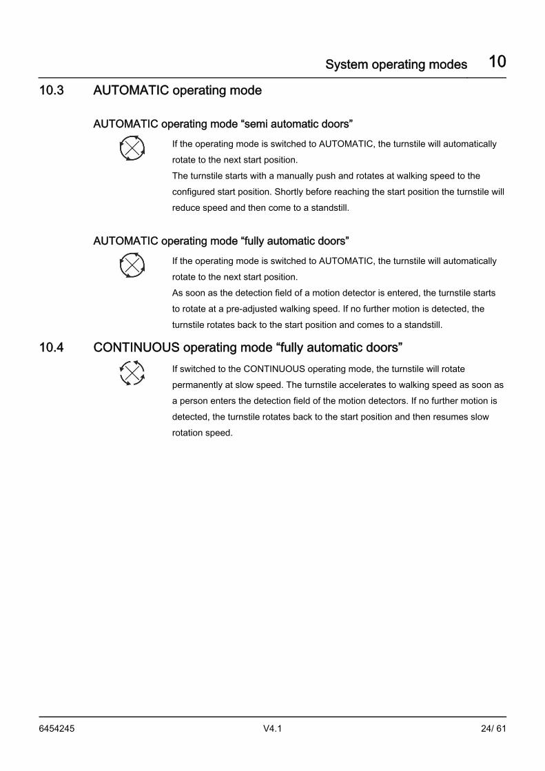
AUTOMATIC operating mode
AUTOMATIC operating mode “semi automatic doors”
If the operating mode is switched to AUTOMATIC, the turnstile will automatically rotate to the next start position. The turnstile starts with a manually push and rotates at walking speed to the configured start position. Shortly before reaching the start position the turnstile will reduce speed and then come to a standstill.
AUTOMATIC operating mode “fully automatic doors”
If the operating mode is switched to AUTOMATIC, the turnstile will automatically rotate to the next start position. As soon as the detection field of a motion detector is entered, the turnstile starts to rotate at a pre-adjusted walking speed. If no further motion is detected, the turnstile rotates back to the start position and comes to a standstill.
CONTINUOUS operating mode “fully automatic doors”
If switched to the CONTINUOUS operating mode, the turnstile will rotate permanently at slow speed. The turnstile accelerates to walking speed as soon as a person enters the detection field of the motion detectors. If no further motion is detected, the turnstile rotates back to the start position and then resumes slow rotation speed.
10.3
10.4

Over current, blocking and heavy starting detection 11
6454245 V4.1 25/ 61
Over current, blocking and heavy starting detection
Over current detection If the turnstile is rubbing hard on the floor surface or runs into an obstacle and blocks, without activating any security devices, this is considered over current. The door control will shut the drive down. The message [08] is shown on the optional IBS –Display. The door system will attempt to restart in the preselected speed after 2 seconds.
Blocking detection Blocking detection: If the turnstile does not move when attempting a restart after an over current detection, this is considered blocking. After a total of 10 unsuccessful consecutive start attempts without rotation (blocking) the door will come to a standstill. The optional IBS-Display will switch from [08] to the message [25]. The door can be started again by normalizing.
Heavy starting detection Heavy starting detection: If the turnstile only moves gradually when attempting a restart after an over current detection, this is considered heavy starting. After a total of 30 unsuccessful consecutive start attempts with gradual rotation (heavy starting), the door will come to a standstill. The optional IBS-Display will switch from [08] to the message [26]. The door can be started again by normalizing.
Overload counter If there is no overload for a duration of approx. 3 sec. after the door starts, (error [08]), the overload counter resets. The overload counter is also reset, when error release [25] or [26] occurs.
11

Function during power failure 12
6454245 V4.1 26/ 61
Function during power failure
CAUTION
Danger of people being trapped inside the turnstile. Visual inspection, check if people have been trapped inside.
If the system is not equipped with an electric turnstile lock, rotational movement will stop immediately during a power failure, and the turnstile can be rotated freely.
NOTICE The turnstile can not be rotated manually during a power failure on a subfloor system with a geared drive!
The key emergency operation button or start button (if available) have no function. Note: The charging status of the emergency power supply (battery) is permanently monitored.
NOTICE An emergency operation is only possible for a certain bridging period with an external (not included) or an integrated UPS (uninterruptible power sub-supply).
If the system is equipped with an electric turnstile lock (unlocked currentless), then the turnstile is unlocked in all operating modes and can be rotated freely, with the exception of subfloor systems with a geared motor. If the system is equipped with an electric turnstile lock (locked currentless), then the turnstile is locked in the LOCKED operating mode. In MANUAL operating mode, the turnstile can be manually rotated to the starting position (locked position), except for subfloor systems with a geared motor, whereby a bolt is engaged in the electric turnstile lock. The turnstile is locked. There is a danger of being trapped inside during this rotation process! In the AUTOMATIC and CONTINUOUS operating modes, the turnstile rotates at slow speed to the next segment position during a power failure using the internal emergency power supply. This is to allow someone inside the turnstile to exit the current segment they are in. Then the system control shuts off. The start button (if available) no longer functions! A locked turnstile can only be released by having a second person press the manual release (Bowden cable)!
12

Function during power failure 12
6454245 V4.1 27/ 61
Function of the pivot wing holding magnets during a power failure In the operating modes LOCKED and MANUAL, the turnstile remains in its current position during a power failure and is turned off. In the operating modes AUTOMATIC and CONTINUOUS, the turnstile the turnstile rotates at slow speed to the next segment position during a power failure using the internal emergency power supply and then shuts off. The holding magnet stoppers are released and the pivot wings can be folded back manually in all modes.
12.1

Function when power is restored 13
6454245 V4.1 28/ 61
Function when power is restored After the power is restored an electronic restart lock is activated. In order to return to AUTOMATIC or CONTINUOUS operating mode, the door control needs to be normalized. To normalize, turn the key-operated switch briefly from AUTOMATIC to the LOCKED position and then back again. The turnstile will start and “search” for the start position (locked position) at slow speed. Then the door is operational again.
Function of the pivot wing holding magnets when power is restored All pivot wings have to be folded back to their original position so that they are securely held by the holding magnet stoppers. After the power is restored an electronic restart lock is activated. In order to return to AUTOMATIC operating mode, the door control needs to be normalized. To normalize, turn the key-operated switch briefly from AUTOMATIC to the LOCKED position and then back again. The turnstile will start and “search” for the start position (locked position) at slow speed. Then the door is operational again.
13
13.1

Safety features of the door 14
6454245 V4.1 29/ 61
Safety features of the door
Emergency stop button
When the emergency stop button is pushed the rotating turnstile is stopped immediately, the turnstile is released and can be rotated manually. After resetting the emergency stop button, the preset operating mode will continue.
NOTICE The turnstile cannot be turned manually on a subfloor door with a geared motor!
Information on motion detectors
NOTICE Moving objects, i.e. loose poster or plants that move in the detection area can trigger an unintentional startup.
Motion detectors are installed on each access side of the door (see “Safety and operating components legend”). These motion detectors detect moving persons. If for example, the detection field of a motion detector is entered in the AUTOMATIC operating mode, the turnstile will start to rotate from the start position. If the detection field is entered in the CONTINUOUS operating mode, (slow speed) the turnstile will accelerate from slow speed to walking speed.
Vertical safety sensors or light barriers drum edge The danger zones on the access sides of the system are secured with vertical safety sensors radiating to the ground or with vertical light barriers, between the rotating turnstile wings and the fixed drum wall edges. These safety sensors or light barriers are only activated when the rotating turnstile wing approaches the drum wall edge by approx. 40 degrees (danger zone). When a safety sensor is activated or a light barrier is interrupted inside the danger zone, the turnstile either stops immediately or switches to slow speed depending on how the parameters have been set on the door control. The stop setting will be held as long as the safety sensor or light barrier is activated. The slow speed setting remains active until the turnstile reaches the home position. Then the turnstile will accelerate and resume until another safety sensor or light barrier is activated. If the safety sensors are no longer activated or the light barrier is no longer interrupted, the turnstile will accelerate and continue at the preset speed.
14 14.1
14.2
14.3

Safety features of the door 14
6454245 V4.1 30/ 61
Information on safety strips
NOTICE There is danger of damaging the safety strips through pointed or sharp objects as well as through aggressive cleaning agents, such as mineral oils or gasoline. This could cause the system to breakdown or cause malfunctions.
Vertical and horizontal safety strips made of soft rubber are installed on the drum wall edges of the door and in the on the bottom and top of the profiles on the turnstile wings in the direction of rotation. When a safety strip is activated, the rotating turnstile stops immediately. When the safety strip is no longer activated, the turnstile automatically resumes rotation.
Horizontal and vertical safety strips Vertical and horizontal safety strips (see “Safety and operating components legend”) made of soft rubber are installed on the drum wall edges of the system and on the outside lower turnstile profiles of the turnstile in the direction of rotation. When a safety strip is activated, the rotating turnstile is stopped immediately. When the safety strip is no longer activated, the turnstile automatically resumes rotation.
14.4
14.5

Optional components 15
6454245 V4.1 31/ 61
Optional components
Electric lock The system is equipped with an electric lock (currentless unlocked). In the LOCKED operating mode, the turnstile is automatically locked via the electric lock in the start position (locked position). During a power failure the turnstile is released and can be rotated freely. The system is equipped with an electric lock (currentless locked). In the LOCKED operating mode the turnstile is automatically locked in the start position (locked position) and unlocked when another operating mode is selected. Unlocking is only possible by pulling the manual release pin (Bowden cable) in the drum canopy, or by pulling the handle on the side of the system on subfloor systems with a timing belt drive (see steps below). Please follow the steps below:
Unlock turnstile
Pull pin
Turn pin to the right until it stops and let go.
Lock turnstile
Turn pin to the left
Release the pin and it will retract. Rotate the turnstile slowly into the start position (locked position) from the exterior until you hear the lock snap into place. Test the turnstile lock, the turnstile should no longer rotate.
15 15.1

Optional components 15
6454245 V4.1 32/ 61
Unlock the turnstile on the side of the system on the bottom
Pull handle
Turn the handle to the right until it stops and then let go.
Lock the turnstile on the side of the system on the bottom
Turn the handle to the left
Release the handle and it will retract downward.

Optional components 15
6454245 V4.1 33/ 61
Turnstile bar-bolt lock The turnstile can be locked with a bar-bolt lock, integrated in the door frame profile. By rotating the profile cylinder together with the ceiling construction, and/or additionally with a fitted socket integrated in the floor.
Turnstile bar-bolt lock with limit switch (option) A limit switch which prevents the turnstile from starting is used to lock the profile cylinder bar bolt lock because the door control is turned off for safety reasons.
Turnstile corner lock The turnstile can be locked with a corner lock, at the bottom of the door frame profile. By rotating the integrated profile cylinder with a fitted socked integrated in the floor.
Lock mechanism status indicator and door position indicator Signal contacts (potential-free NO contacts maximum contact load 24 volt AC/DC/0.3 amps) for indicating the locked state of the turnstile and / or night shield. The position of the night shield wing can also be indicated. In some countries (VdS) tested signal contacts (potential-free NO contacts, tested according to VdS class C, maximum contact load 24 volt AC/DC/0.3 amps) are required according to the German Property Insurers Association. These are then suitable for use in certified alarm systems.
Light switch The lighting can be or is connected to an on-site light switch or controlled by the building control system to be switched OFF or ON.
15.2
15.2.1
15.3
15.4
15.5

Optional components 15
6454245 V4.1 34/ 61
Key pivot contact
When the key pivot contact is activated (see “Safety and operating components legend”), the turnstile starts and rotates a minimum of 360° in all operating modes except for MANUAL mode. In the MANUAL mode or when the emergency stop switch is activated, the turnstile can only be rotated manually, with the exception of subfloor system with a geared drive. In the LOCKED mode the turnstile will automatically lock again (if an electric lock is available).
Or – on-site code card reader (CKL)
Disabled button Automatically starts a temporary slow rotation speed
When the disabled button (see “Safety and operating components legend”) is pressed in the AUTOMATIC or CONTINUOUS operating mode, the turnstile rotates at a slow speed. With the fully automatic, the motion detectors are deactivated during this time. With the semi-automatic, the turnstile starts after activating the disabled button. The slow speed covers one complete 360 degree rotation, including one extra segment. The turnstile remains stopped in the start position. The revolving door then resumes in its programmed mode.
15.6
15.7

Optional components 15
6454245 V4.1 35/ 61
Start button
IMPORTANT In the LOCKED mode, the start button function is disabled after 10 minutes.
After pressing the start button the turnstile starts and turns one complete rotation to prevent confinement. The start button does not work during a power failure.
Emergency open button (pivot wing)
After pressing the emergency open button (pivot wing), (see “Safety and operating components legend”) the turnstile immediately comes to a stop. The pivot wing stopper latches are released (see arrow). The pivot wings are released and can be folded back manually. To restore normal operation of the system, the emergency open button must be reset first. When the emergency open button is reset, then all the pivot wings must be manually rotated to their original position. The pivot wing stopper latches will hold the pivot wings in their original position (see arrow). To start the AUTOMATIC operating mode, the door control must be renormalized. To release the restart lock, turn the key-operated switch briefly to the LOCKED position and then back to the AUTOMATIC operating mode. The turnstile will start to calibrate, whereby the turnstile will go around 1-2 complete rotations at slow speed. After the calibration is complete the door is operational again.
15.8
15.9

Optional components 15
6454245 V4.1 36/ 61
Key emergency operation button
WARNING
There is a risk of entrapment and entanglement, causing injury Activated safety sensors or safety strips are ignored during emergency operation. This can lead to personal injury or property damage due to carelessness. In a hazardous situation, press the emergency stop button immediately. The operator must always maintain visual contact to the door from the key emergency operation button!
If the operation of the door is prevented for example, by a defective sensor, the turnstile can still be rotated to a desired position, in the direction of rotation by an authorized person, via the key emergency operation button (see “Safety and operating components legend”). Function: triggers a rotation at reduced speed. It can ignore safety sensors. The emergency stop button remains the overriding function.
Key Operating mode
Function
activated
emergency operation
▪ As long as the key emergency operation button is turned and held in the direction of the arrow, the turnstile will rotate and stop in the home position (locked position) automatically (deadman function).
▪ When the key emergency operation button is released, the turnstile will stop in its current position.
Forward sensors turnstile wing Forward sensors, which are integrated in the ceiling or mounted directly on the turnstile wing frame, secure the hazardous area in front along the vertical edge of the turnstile wing down to the floor. The sensors function continuously during rotation. When activated, rotation of the turnstile is stopped. When the sensors are no longer activated, the turnstile will continue to rotate.
15.10
15.11

Optional components 15
6454245 V4.1 37/ 61
Vertical sensors strips drum walking area Co-rotating, vertical sensors, radiating to the floor, are mounted on top of the turnstile wings and/or on top of the turnstile centre part. They secure the danger zone from approx. 12-20 cm in front of each turnstile wing to the turnstile centre. When a safety sensor is activated within the danger zone, the turnstile will switch to slow speed or stop depending on parameterization. Slow speed is maintained until a horizontal or vertical electric safety strip on the turnstile is activated. Then the turnstile will stop. When the electric safety strip is no longer activated and no safety sensors are activated, the turnstile will start and accelerate to the preset walking speed.
Vertical multifunctional sensors drum walking area Co-rotating, vertical sensors, radiating to the floor, are mounted on top of the rotating wings. They secure the danger zone from approx. 15 -20 cm in front of each turnstile wing to the turnstile centre. If a person is detected within approx. 2/3 of the width of the rotating wing while the turnstile is rotating, the turnstile will immediately stop. The turnstile will also stop immediately if a person is detected in the central area within approx. 1/3 of the width of the rotating wing while the turnstile is rotating. If there are no people or objects etc., within the detection area of the sensors, the turnstile will start again and accelerate to walking speed.
Horizontal-pivot wing hinge light barrier (stop) Co-rotating, horizontal light barriers, radiating to the floor, are mounted (see pos. no. 34 “Safety and operating components legend”) on the bottom along the pivot wing joints. They secure the danger zone between the floor and each pivot wing joint construction. If a light barrier is activated while the turnstile is in motion, the turnstile will stop immediately. If there are no more people or objects etc., within the detection area of the light barriers, the turnstile will start again and accelerate to walking speed.
Air curtain control Direct ventilation to the interior via an air duct built into the doorway. The air curtain is controlled by a potential-free door contact that triggers once the turnstile starts to rotate.
15.12
15.13
15.14
15.15

Optional components 15
6454245 V4.1 38/ 61
Foldable turnstile wings and/or foldable drum walls The system may be equipped with foldable turnstile wings and/or, in the case of a three wing system, with foldable drum walls. If a turnstile wing and/or a drum walls have been manually folded open, the system control will be signalized of its status via a monitoring contact. Rotation would simultaneously stop immediately and the system control will turn off. In order to return to operation, all the turnstile wings and/or drum walls must be manually placed back to their original position. Then the turnstile will start again and resume in the preset operating mode.
Home positions K31 / K41 - Interior
Exterior
Folded positions K31 / K41 - Interior
Exterior
Folded drum walls K31
15.16

Optional components 15
6454245 V4.1 39/ 61
Pivot wing button K31 / K41 (break out) When the button is activated, the turnstile rotates to the home position (see left graphic), in all operating modes. The holding magnet then releases the respective pivot wing. The pivot wing can now be manually folded back (see graphic example). This allows for faster passage through the system. After resetting the switch, all pivot wings must be manually reengaged to their original position. The turnstile starts automatically and resumes in the preset operating mode.
Folded positions K31 with break out Folded positions K41 with break out
Interior Interior
Exterior Exterior
15.17

Conduct during malfunctions 16
6454245 V4.1 40/ 61
Conduct during malfunctions
IMPORTANT If malfunctions that endanger the safety of individuals occur, the system must be turned off. It may not be turned back on until the problem has been resolved by a professional and the danger no long exists.
Possible troubleshooting
NOTICE Some malfunctions can be rectified by the operator themselves (see troubleshooting tips). If the tips do not resolve the problem, please contact your local service centre. Before calling, please note the information shown on the optional IBS system display. This information provides the technician with important information for troubleshooting.
16
16.1

Tips on troubleshooting 17
6454245 V4.1 41/ 61
Tips on troubleshooting To eliminate malfunctions, it is necessary to disable the electronic restart lock on the door control through normalization. For this, turn the key-operated switch from LOCKED to AUTOMATIC operating mode and back again. The turnstile will start at slow speed and “search” for the home position. Then the door is operational again. Malfunctions and their causes, as well as possible solutions which can be performed by the operator, are listed below. If the solutions listed are not successful, the operator must disconnect the main power supply and call the service centre.
Malfunctions Causes Solutions
Turnstile is blocked, can not be electrically unlocked
▪ Lock does not open ▪ Lock is jammed in the lock latch ▪ Lock is defective
▪ Switch to MANUAL operating mode and shake turnstile briefly
Door does not function or turnstile rotates irregularly
▪ Press emergency stop button ▪ Cable break ▪ Short circuit ▪ No power supply or restart lock is
activated ▪ Over current pressure control activated.
Excessive friction on the turnstile wing sealing brushes between the floor and the drum wall
▪ Obstacle in the rotation area ▪ Geared motor damage ▪ Door control defective ▪ Electric safety strips activated ▪ Safety sensors activated by a person
or object ▪ Foreign object jammed ▪ Safety sensors surface is dirty ▪ Pivot wing (if available) is not engaged
properly in the locking device ▪ Night shield is not completely open ▪ Night shield limit switch is defective ▪ Control is defective
▪ Reset emergency stop button
▪ Check power supply, call electrician if necessary!
▪ Eliminate floor inequalities, if necessary remove the dirt accumulated under the mat
▪ Remove obstacles ▪ Check electric safety
strips for damages, clean surface with soapy water
▪ Remove foreign objects
17

Overview of the door parameters 18
6454245 V4.1 42/ 61
Overview of the door parameters
Software versions K30_121 / K40_121
Door types K31-V/xx + K31-H/xx / K41-V/xx + K41-H/xx
MP Description Default set-ting
Setting range
02 Acceleration time 08 00.. 15
03 Crawl distance 10 01.. 255
04 Crawl speed 08 05.. 20 [%]
05 Slow speed 30 10.. 100 [%]
06 Fast speed 60 10.. 100 [%]
07 Over current 100 10.. 100 [%]
08 Emergency stop brake time 05 00.. 15
09 Activation point drum sensor 90 00.. 255 [drum edge-0..90°]
10 Drum edge sensor 1 Sensor type Output Value
Test low active NO 0
Test low active NC 1
Test high active NO 2
Test high active NC 3
No test NO 4
No test NC 5
11 Starting angle 00 00 [man. Start OFF] 01..255 [00..45°]]
12 Brake time - crawl speed sensor 08 00..15
13 Drum deactivation sensor 00 00..255 [drum edge - 0..90°]
14 Turnstile released in OFF 00 0 [OFF] 01..20 [sec.]
15 Lock type 2 Type Without power
*VRM Value
monostable CLOSED yes 0
monostable OPEN yes 1
monostable CLOSED no 2
monostable OPEN no 3
18

Overview of the door parameters 18
6454245 V4.1 43/ 61
MP Description Default set-ting
Setting range
16 Sensor type crawl 1 Sensor type Output Value
Test low active NO 0
Test low active NC 1
No test NO 2
No test NC 3
17 Emergency-Stop-Module 1 0…1 [without .. with]
18 Number of rotating segments 3 / 4 1 …4 [1/3.… 4/3 rotations, 90°..480°]
19 Lock delay time 0 0 … 20 [sec.] only works for semi-automatic- MP10>0
20 Drum sensor function 0 0 … 1 [stop .. crawl]
21 Release emergency stop 0 0 … 1 [manual .. automatic]
22 Permanently locked 0 00..1 [Off .. On]
*VRM = lock mechanism status indicator

IBS-System display (service) 19
6454245 V4.1 44/ 61
IBS-System display (service) The optional IBS-System display is a microprocessor-controlled display and programming unit, which can be set or display special functions and door parameters. Thanks to an integrated system analyser the respective code will be shown in the display when a safety device is activated or a system failure occurs. Only the last code will be displayed. The display reading can be deleted by pressing any key. Then the display shows [-----].
When you push the telephone key a scroll text showing the customer service centre telephone number is displayed until another key is pushed. After the power supply is turned on, the numbers [0] to [4] will show one after another in the display, indicating data transfer between the IBS and the door control. Then the display shows [-----]. The IBS-System display is now in basic mode. The mode of the key-operated switch is shown by a round green LED above the respective operation key. Selecting the program mode is done by using the shift key, whereby the current mode is displayed by a green or a yellow triangle LED.
19

IBS-System display (service) 19
6454245 V4.1 45/ 61
Keys / Display / LED Significance Function
Telephone key Retrieve service number
Basic mode OFF mode
Program mode Down key
Basic mode MANUAL mode
Program mode Up key
Basic mode AUTOMATIC mode
Program mode Cursor control
Basic mode CONTINUOUS mode
Program mode Input confirmation ENTER
Shift key Basic / Program mode
Display Menu number display, parameter
value, system failure or operating mode
Green LED (circle) Operating mode display
Green LED (triangle) Basic mode display
Yellow LED (triangle) Program mode
NOTICE Mode selection Switching operating modes to and between OFF-AUTOMATIC-CONTINUOUS-MANUAL is not possible with the IBS-System display.

Normalizing and calibrating with the IBS system display 20
6454245 V4.1 46/ 61
Normalizing and calibrating with the IBS system display
Initialization – activation of the restart lock when power returns Once the power is turned off the initialization process automatically starts. For security reasons an electronic restart lock is activated. The message [06] is shown on the optional IBS display. This initialization can also be manually activated by briefly, simultaneously
pressing the following buttons , , and on the IBS system display. You can also press the reset button briefly in the key-operated switch to start the initialization program.
Normalization - Cancel the restart lock The message [06] is shown on the optional IBS display. Before the turnstile can start, the restart lock must be disabled by normalizing. To do so, turn the key-operated switch from AUTOMATIC to LOCKED and back again. The turnstile will start on slow speed and “search” for the home position (locked position). The IBS system display will change from [06] to this display "-----". The door is then ready for use.
Calibrate – turnstile positioning Calibration is required for the exact positioning of the turnstile. If the reset button on the key-operated switch is pushed for longer than five seconds, the calibration process will be activated in every operation mode. As with initialization, this will reset the entire processor system. During this time the turnstile will rotate approx. 1-2 rotations at crawl speed. After the calibration process is complete the revolving door is ready for use. The calibration
process can also be activated by simultaneously pressing the following buttons ,
and on the optional IBS system display for longer than 5 seconds.
20 20.1
20.2
20.3

Troubleshooting per IBS-Display 21
6454245 V4.1 47/ 61
Troubleshooting per IBS-Display The door control must be reinitialized and normalized after every error. To do so, press the reset button on the key-operated switch for approx. 1 second. Then turn the key-operated switch from AUTOMATIC to the LOCKED position and back again. Then you can choose the desired mode of operation. If the solutions listed are not successful, the operator must disconnect the main power supply and call the service centre.
IBS code number
Operating and error status
Causes Solutions
Standard operation ▪ No error -
Lock does not open ▪ Lock is jammed in the lock latch
▪ Manually rotate the turnstile slightly to the left or right
▪ Activate manual release ▪ Select MANUAL
operation
Lock does not close ▪ System error or defective lock
▪ Rotate the turnstile manually to the locked position (lock must click into the locking device)
Rotating sensor CRAWL activated
▪ Person or object is detected
▪ Dirty sensor lens ▪ Not calibrated correctly ▪ Floor reflection
▪ Clean lens ▪ Calibrate according to
manufacturer’s specifications
▪ Dry floor
Emergency open button activated
▪ Emergency open button activated
▪ Cable break ▪ Short circuit
▪ Reset emergency open button
Emergency stop button activated
▪ Emergency stop button activated
▪ Cable break ▪ Short circuit
▪ Reset emergency stop button
21

Troubleshooting per IBS-Display 21
6454245 V4.1 48/ 61
IBS code number
Operating and error status
Causes Solutions
Restart lock activated ▪ Power failure ▪ Loose connection in
power plug
▪ Initialize with reset button
▪ Normalize with key-operated switch
System error # 01 ▪ Power failure ▪ Loose connection in
power plug
▪ Check power supply ▪ Initialize with reset
button ▪ Normalize with key-
operated switch
Over current ▪ Excessive friction be-tween the floor and the drum wall from the brush seals on the turnstile wings
▪ Obstruction in rotation area
▪ Motor gearbox damage
▪ Eliminate floor elevations
▪ Remove dirt from under floor mat
▪ Remove obstruction
Horizontal or vertical electric safety strips on turnstile activated
▪ Person activated safety strip
▪ Foreign object jammed ▪ Dirty surface
▪ Remove foreign object and check safety strip for damage
▪ Clean surface with soapy water
Vertical safety strip drum edge activated
▪ Person activated safety strip
▪ Foreign object jammed ▪ Dirty surface
▪ Remove foreign object and check safety strip for damage
▪ Clean surface with soapy water
Pivot wing opened or night shield not completely opened
▪ Wing is not properly engaged in the latch
▪ Night shield is not completely opened
▪ End switch / night shield defective
▪ Cable break
▪ Fold wing back to original position
▪ Open the night shield completely

Troubleshooting per IBS-Display 21
6454245 V4.1 49/ 61
IBS code number
Operating and error status
Causes Solutions
Drum edge sensor activated ▪ Sensor activated by person / object
▪ Dirty sensor lens ▪ Not calibrated correctly ▪ Floor reflection
▪ Clean lens ▪ Calibrate according to
manufacturer’s specification
▪ Dry floor
Power failure ▪ No power ▪ Check power supply ▪ Activate manual release
Speed control defective ▪ Encoder is defective ▪ Signal path is
interrupted ▪ Short circuit track A
and B interchanged
-
Lock disengaged ▪ 24 V DC interrupted ▪ VRM-contact connection
disturbed
▪ Activate emergency stop button
▪ Activate manual release
TA4- power amplifier defective
▪ Hardware defect ▪ Motor damage ▪ Short / ground short to
motor cable
-
TA4- battery empty ▪ Power failure ▪ Defective battery ▪ Battery polarity reversed ▪ TA4-charging circuit is
defective
-
Sensor drum edge defective ▪ TA4-Test signal is not correct
▪ Internal sensor test is negative
-
Enter service code - -
IBS does not respond ▪ IBS communication error
▪ IBS / TA4 defective
-
Not in use - -

Troubleshooting per IBS-Display 21
6454245 V4.1 50/ 61
IBS code number
Operating and error status
Causes Solutions
Rotation sensor defective ▪ TA4-Test signal is not correct
▪ Internal sensor test is negative
-
EMERGENCY STOP module does not respond
▪ Monitoring is defective ▪ EMERGENCY STOP
module is defective
-
Motor relay does not respond
▪ Motor short circuit ▪ Contacts stuck
-
Turnstile blocked ▪ See error code [08] ▪ See error code [08]
Turnstile rotates difficultly (startup overload)
▪ See error code [08] ▪ See error code [08]

Function and safety inspection 22
6454245 V4.1 51/ 61
Function and safety inspection
General information At the time of commissioning, in accordance with the applicable laws and regulations (DIN standards and machinery directive), the operator of the system is solely responsible for user safety and repair and maintenance, after take over, according to Operational Safety Regulations (Betr.SichV).
Inspection and maintenance Regular inspection and maintenance of the system by trained and authorized personal from the manufacturer, is the best guarantee for long life and trouble-free secure operation. These control and maintenance operations are required at regular intervals, following the manufacturer's instructions and the relevant legal requirements.
Spare parts / liability Reliable and trouble free operation of the door is only guaranteed when using parts that were recommended by the manufacturer. The manufacturer declines any liability for damages resulting from unauthorized modifications to the door or the use of parts that are not permitted.
22 22.1
22.2
22.3

Function and safety inspection 22
6454245 V4.1 52/ 61
Operator duties According to principles for inspecting automatic door systems, in particular according to case law of safety obligations, automatic door systems must be inspected by a qualified technician before commissioning and thereafter according to the manufacturer recommendation. It is particularly important for the protection of people, to observe and to comply with the requirements for public access facilities! The operator is responsible to fulfill the duties required for the door system.
Task To be conducted by Time of implementation
Entry in log book required
Maintenance and cleaning
Operator Weekly or if required No
Function and safety check
Operator Monthly No
Regular maintenance Technical expert 1 × per year, or according to country specific directives and regulations
Yes
Regular testing (inspection)
Technical expert 1 × per year, or according to country specific directives and regulations
Yes
Regular testing (inspection) for door systems in escape route
Technical expert 2 × per year, or according to country specific directives and regulations
Yes
22.4

Visual and functional inspection 23
6454245 V4.1 53/ 61
Visual and functional inspection
Monthly inspection procedures Monthly tests and inspections of the individual components are performed by the operator mainly to prevent accidents caused by improper handling of the system. Depending on the model of door, we recommend the following inspections steps.
Pos.-No.:
Test / Inspection Procedure Results expected
1 Function test motion detectors
▪ Select the AUTOMATIC operating mode.
▪ When the turnstile comes to a standstill, enter into the detection area of the motion detector.
▪ Conduct this test from the interior and exterior.
▪ The turnstile must start to rotate in time.
6, 9, 16
Visual inspection of all safety strips
▪ Select the MANUAL operating mode.
▪ Visually inspect all safety strips.
▪ The safety strips must not have any mechanical damage and they must be installed correctly and firmly over the entire length.
24 Function test emergency stop button
▪ Start the turnstile rotating in AUTOMATIC operating mode.
▪ Press the emergency stop button.
▪ Reset the emergency stop button.
▪ The turnstile must stop immediately.
▪ After resetting the turnstile will start again.
23 23.1

Visual and functional inspection 23
6454245 V4.1 54/ 61
26 Function test start button
▪ Turn the key-operated switch to the LOCKED position and wait for the turnstile to stop. Remember in which segment the start button is located.
▪ The examiner enters into the locked segment and waits for the turnstile come to a standstill and lock. Then presses the start button.
▪ After pressing the start button, the turnstile starts, completes one full rotation and stops in the home position (locked position) and locks again. The examiner can now exit the door.
IMPORTANT Caution: risk of entrapment! When conducting this test, a second person must be present to press the manual release in case the other person gets trapped inside a segment of the door.
Function test locked mode
▪ Select LOCKED operating mode. Do not enter the door!
▪ Verify whether the turnstile is locked by trying to push it manually.
▪ The turnstile will lock securely.
23 Option-
ally external
Function test key emergency operation button
▪ Place the door in the AUTOMATIC or CONTINU-OUS operating mode.
▪ Turn the key emergency operation button and hold in position.
▪ As long as the key emergency operation button is being turned and held, the turnstile will continue to rotate in the direction of rotation selected.
▪ When the key emergency operation button is released, the preset operating mode will resume.
25 Function test disabled button
▪ Start the turnstile rotating in the AUTOMATIC operating mode.
▪ Press the disabled button. ▪ Conduct this test from the
interior and exterior.
▪ The turnstile must reduce speed and continue to rotate at least 360° at reduced speed.

Visual and functional inspection 23
6454245 V4.1 55/ 61
27 Option-
ally external
Function test key pivot contact
▪ Select the LOCKED operating mode.
▪ Briefly activate the key pivot contact.
▪ The turnstile will unlock, turn one complete rotation and lock again.
62, 63, 64, 65
Visual inspection of the instructions and labeling (buttons / switches)
▪ Verify that labels and instructions are present and legible.
▪ All warnings and instructions must be present, legible and firmly attached.
70 Visual inspection of glass labeling
▪ Verify that all glass labels are present.
▪ The glass labels must be present and attached firmly at eye level.
Visual inspection of floor mats
▪ Inspect the floor mats for tripping hazards, unevenness, damages and dirt accumulation.
▪ The floor mat must be free from tripping hazards, unevenness, damages and dirt accumulation.
CAUTION
Risk of burning, hot surfaces! • Risk of burning hands when replacing components.
Allow components to cool for at least 5 minutes before replacement and wear safety gloves if necessary.
Visual inspection lighting
▪ Verify whether the lights are installed correctly and turn them on.
▪ Lights must be installed correct and function.
CAUTION
Burn hazard, hot surfaces! Risk of burning the hands when replacing bulbs! Allow to cool at least 5 minutes before replacing bulbs and, if necessary, wear protective gloves.

Night shield 24
6454245 V4.1 56/ 61
Night shield
NOTICE The door is equipped with a night shield located on the exterior entrance. If it is manually pushed out of the open position while rotating, the turnstile will immediately stop for safety reasons. For safety reasons, the automatic mode only functions if the night shield is completely open. During a power failure, the status of the night shield remains LOCKED or UNLOCKED.
Manual night shield Night shield with mechanical bar-bolt lock or hook bolt lock The night shield can be locked and unlocked with profile cylinder locks integrated in the door frames. If the night shield is in locked position, then it must be unlocked and completely pushed open manually. Then the operating mode of the door can be selected.
24
24.1
Night shield 24
6454245 V4.1 57/ 61
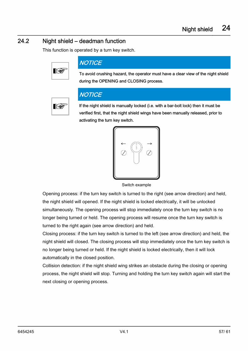
Night shield – deadman function This function is operated by a turn key switch.
NOTICE To avoid crushing hazard, the operator must have a clear view of the night shield during the OPENING and CLOSING process.
NOTICE If the night shield is manually locked (i.e. with a bar-bolt lock) then it must be verified first, that the night shield wings have been manually released, prior to activating the turn key switch.
Switch example
Opening process: if the turn key switch is turned to the right (see arrow direction) and held, the night shield will opened. If the night shield is locked electrically, it will be unlocked simultaneously. The opening process will stop immediately once the turn key switch is no longer being turned or held. The opening process will resume once the turn key switch is turned to the right again (see arrow direction) and held. Closing process: if the turn key switch is turned to the left (see arrow direction) and held, the night shield will closed. The closing process will stop immediately once the turn key switch is no longer being turned or held. If the night shield is locked electrically, then it will lock automatically in the closed position. Collision detection: if the night shield wing strikes an obstacle during the closing or opening process, the night shield will stop. Turning and holding the turn key switch again will start the next closing or opening process.
24.2

Night shield 24
6454245 V4.1 58/ 61
Semi-automatic night shield This function is operated by a turn key switch.
NOTICE To avoid crushing hazard, the operator must have a clear view of the night shield during the OPENING and CLOSING process.
NOTICE If the night shield is manually locked (i.e. with a bar-bolt lock) then it must be verified first, that the night shield wings have been manually released, prior to activating the turn key switch.
Switch example
Semi-automatic night shield drive with electric lock The night shield is closed and electrically locked (if available). By turning the turn key switch to the right briefly (see arrow direction), the night shield will unlock and open in all operating modes of the revolving door. The turnstile can only be started when the night shield is completely opened. By turning the turn key switch to the left briefly (see arrow direction), the night shield will close and lock in all operating modes of the revolving door. The opening or closing process can be switch to the opposite direction by turning the turn key switch to the other side. Securing sensors: if the detection area of the security sensors is entered during the closing process, the night shield will open (reverse) immediately. If no security sensors are activated the night shield will close and lock automatically. Collision detection: if the night shield wing strikes an obstacle during the opening or closing process, the night shield will stop and remain at a standstill. The next attempt to open or close will start from the obstruction area at slow speed.
24.3

Night shield 24
6454245 V4.1 59/ 61
Fully automatic night shield It is operated with a door open button, or a turn key switch, or an on-site code card reader.
NOTICE To avoid crushing, the operator must have a clear view of the night shield during the OPENING and CLOSING process.
Fully automatic night shield drive with electric lock: Place the door in the LOCKED operating mode. The night shield is closed and electrically locked. By pressing the door open button, or using the turn key switch or on-site code card reader, the night shield will unlock and open up completely. Once the night shield is completely opened, the turnstile will start, turn one complete rotation at slow speed and come to a standstill in the home position. Then the night shield closes again automatically and locks. In the operating modes AUTOMATIC, CONTINUOUS and MANUAL, the night shield unlocks itself, opens automatically and remains open. If switched to the LOCKED operating mode, the night shield closes again automatically. Security sensors: if the detection area of the security sensors is entered during the closing process, the night shield will open (reverse) immediately. If no security sensors are activated the night shield will close and lock automatically. Collision detection: if the night shield wing strikes an obstacle during the closing process, the night shield will stop and open again. The next attempt to close will start from the obstruction area at slow speed. The night shield will also stop, if its wing strikes and obstacle during the opening process. The next attempt to open will start at slow speed.
24.4

Cleaning and care 25
6454245 V4.1 60/ 61
Cleaning and care
DANGER
Warning: risk of fatal electric shock! • Risk of death by electrocution
Do not touch the drive system while the main power is connected. Do not spray water into the drive system.
NOTICE Before cleaning, select MANUAL mode and also press the emergency stop button. Rinse cleaned surfaces with a clean, damp cloth.
IMPORTANT Keep the system clean from dirt, leaves, snow and ice! • If heavily soiled, please contact a professional. • Do not use road salt or gravel in front of the entrance area or within the
system. • We recommend that you impregnate the safety strips with water repellent
care products.
IMPORTANT Any other cleaning products, not mentioned here, should not be used!
What Interval Cleaning agent
General parts Weekly Damp cloth, neutral to low alkaline, wetting agent solution / vinegar diluted with water
Sensors / safety strips Weekly Synthetic cleaner
Floor mats Weekly Vacuum cleaner / carpet cleaner
Display cases Weekly Commercial glass cleaner
25

Dismantling and disposal 26
6454245 V4.1 61/ 61
Dismantling and disposal
IMPORTANT All machine parts must be sorted by type of material and disposed of according to local regulations and guidelines.
The automatic door mainly consists of the following materials:
Aluminum: ▪ Linking profiles ▪ Gearbox ▪ Door wing profiles and side profiles ▪ Various profiles and small parts ▪ Drive panel
Steel / iron parts: ▪ Stainless steel casing ▪ Floor panel ▪ Box recess for floor installation ▪ Optional spacer or reinforcement profiles ▪ Gear components, springs ▪ Various small parts like fittings, covers, linking parts, etc.
Glass: ▪ Door wings and side panels
Various electronic and electromechanical components: ▪ Sensors, control and operator components ▪ Lead batteries and nickel-cadmium rechargeable batteries
Various plastics: ▪ Rollers ▪ Cable clips, coupling and linking parts ▪ Sealing profiles ▪ Casing of electromechanical components and sensors
26


Contact
Î record UK limitedHead Office: Unit D, 9 Watt Place – Hamilton International Park – Blantyre – G72 0AH – UK
Central Office: Batley Business Centre – Unit 40 – Annexe 2 – Technology Drive – Batley – WF17 6ER – UK
Southern Office: 17 Invincible Road – Farnborough – GU14 7QU – UK
tel.: + 44 1698 376411 – fax: + 44 1698 376422 – [email protected] – www.recorduk.co.uk
Î record global exportagtatec ltd – Allmendstrasse 24 – 8320 Fehraltorf – Switzerland
tel.: + 41 44 954 91 91 – e-mail: [email protected] – www.record.global
Î Headquartersagtatec ltd – Allmendstrasse 24 – 8320 Fehraltorf – Switzerland
tel.: + 41 44 954 91 91 – e-mail: [email protected] – www.record.group
Subj
ect t
o te
chni
cal m
odifi
catio
ns –
Cop
yrig
ht ©
agt
atec
ag
n°64
5424
5 –
Man
ufac
ture
r: ag
tate
c ag
– A
llmen
dstra
sse
24 –
832
0 Fe
hral
torf
– Sw
itzer
land
record your global partner for entrance solutions
your global partner for entrance solutions