automatic exterior orientation procedure for low-co …
TRANSCRIPT

AUTOMATIC EXTERIOR ORIENTATION PROCEDURE FOR LOW-COST UAV PHOTOGRAMMETRY USING VIDEO IMAGE TRACKING TECHNIQUE AND GPS
INFORMATION
T. Anai a, *, T. Sasaki a, K. Osaragi a, M. Yamada a. F. Otomo a, H. Otani b
a R&D Center, TOPCON CORPORATION, 75-1, Hasunuma, Itabashi, Tokyo –[email protected] b Positioning Business Unit, TOPCON CORPORATION, 75-1, Hasunuma, Itabashi, Tokyo
Commission V, ICWG V/I
KEY WORDS: Automation, Exterior Orientation, Matching, Video, Tracking, GPS, Robust ABSTRACT: In this paper, we propose the automatic exterior orientation procedure for the Low-cost Unmanned Aerial Vehicle (UAV) photogrammetry. The Low-cost UAV has become useful tool for low altitude photogrammetry from the rapidly increasing of automatic control technique in past several years. However, automatic exterior orientation is still important issue. The most important point of automatic exterior orientation is the automatic detection of corresponding points in each still image. For this goal, the authors have developed the automatic corresponding point detection technique using both video Image and still images. The video image of this investigation is obtained with still images simultaneously. Therefore, the tracking result of video image gives robust correspondence information between each still image. Moreover, the exterior orientation procedure using GPS information from UAV and minimum ground control points have been investigated. This paper is structured as follows. At the first we describe the over view of automatic exterior orientation procedure in this investigation. As the next, the details of tracking of common feature points and robust bundle adjustment are described. Also, accuracy assessment of this automatic exterior orientation procedure is described. Finally some conclusion is given.
* Corresponding author.
1. INTRODUCTION
The aerial triangulation in photogrammetry using mass images taken by the Low-cost UAV has become possible easily by rapidly increasing of automatic flight control technique of Low-cost UAV in These past several years. The Low-cost UAV which integrated GPS and IMU usually has ability to perform autonomous flight and automatic navigation along planned waypoints. These waypoints are usually planned beforehand easily by dedicated software as considering the camera parameter, area of interest, overlap of image, altitude and so on. Moreover, still images at planned waypoints are acquired automatically by digital still camera mounted on UAV. Therefore, Low-cost UAV system is widely used as the useful platform in the low altitude application field of photogrammetry such as agriculture, archaeology, traffic monitoring, and disaster area surveying (Remondino, 2011). However, in order to perform the fully automatic aerial triangulation using mass still image in low altitude application field, some problems have to be resolved. The automatic detection of corresponding point from common features visible in each still image is the most important problem. In the case of low altitude application using UAV, this problem becomes complex issue because the geometry of images is similarly to close-range photogrammetry. In the case of standard altitude application of automatic aerial triangulation, direct geo-referencing approach using GPS and IMU on UAV is often considered. But, direct geo-referencing approach using GPS and IMU on Low-cost UAV is difficult in the case of low altitude application because the GPS observation is more affected by environment than standard case of aerial triangulation. Therefore, the automatic detection of
corresponding point between each still image has to be performed by image based approach. The automatic detection of corresponding points using coded target is one of the popular approaches. However, the photogrammetry using Low-cost UAV is often used under the difficult situation for direct ground surveying such as disaster area or cultural heritage. Consequently, only minimum targets can locate in area of interest, but the correspondence of all images is not provided by these targets. Another important problem is the robust exterior orientation using automatic detected corresponding points, GPS information at waypoints from UAV, minimum ground control points (GCP). Because the corresponding points from common feature are often including error and also the positioning information from Low-cost UAV often includes outlier, robust exterior orientation has to be investigated. On the other hand, the authors have been concentrating to investigate the Structure from Motion (SfM) technique using both video image and GPS in late years (Anai, 2010). In these investigations, we have proposed the robust feature point tracking method based on the “Orientation Code” (OC) image processing (Ullah 2001). Also, bundle adjustment method for video image that uses both SfM technique and GPS data with considering error in GPS observation. If both video image and still images are obtained from UAV, the tracking information of video image gives the robust corresponding information between each still image. From these circumstances mentioned above, this paper proposes about automatic corresponding point detection method using both video images and high resolution still images. Also, the automatic exterior orientation procedure using corresponding points, GPS and minimum GCP is also described.
International Archives of the Photogrammetry, Remote Sensing and Spatial Information Sciences, Volume XXXIX-B7, 2012 XXII ISPRS Congress, 25 August – 01 September 2012, Melbourne, Australia
469

2. AUTOMATIC EXTERIOR ORIENTATION USING VIDEO IMAGE AND STILL IMAGES
This section describe about the automatic exterior orientation process in this investigation. In order to perform automatic detection of corresponding points from discontinuous high resolution still images without using coded target or manual operation, the keypoint detector and descriptor such as SIFT (D. G. Lowe. 2004.) or SURF (H. Bay. 2006.) are widely used now. By the way, if assume that the video image between discontinuous still images are obtained, video image sequences gives information about the motion of corresponding points. Therefore, the authors developed the procedure of automatic detection of corresponding points using video image sequences and high resolution still image. Moreover, robust exterior orientation that using corresponding points, GPS on UAV and minimum ground control point was also investigated. 2.1 Integrated Devices on UAV
The authors have developed the UAV system which has ability of acquiring video image and still image simultaneously. Figure1 shows the UAV system of this investigation. This system is based on “AscTec Falcon8” which developed by "Ascending Technologies GmbH". Table1 shows the details of integrated devices of this UAV system. The finder image of digital still camera RICHO GX200 is connected to video recorder by NTSC video line. Therefore, high resolution still images (12 mega-pixels) at each waypoint and the video image (VGA size) during a flight are obtained. The synchronization between video image and still images is performed by detection of shuttered frame from video image sequences. Also, the positioning results at each waypoint are obtained by KML format file as the function of “AscTec Falcon 8”.
Figure 1. UAV of This Investigation
UAV ASCTEC Falcon 8 Payload: 500g Flight Time: 16~18 min
GPS Ublox LEA-5T GPS L1 frequency, C/A Code GALILEO Open Service L1 frequency
SBAS surport Digital Camera Ricoh GX-200 Resolution:4000×3000 Pixel
Focal Length: f=5.1mm(at wide side)
Video Recorder kingdom System Technology Angel Eye
Input Video Signal: NTSC/PAL Recording Resolution: 640 × 480 pixel
Video File Format: AVI(mepg4)
Table1. Details of Integrated Devices
2.2 Flow of Automatic Exterior Orientation procedure
Figure 2 shows the flow of automatic exterior orientation procedure in this investigation. The waypoint planning and flight control are performed by “AscTec autopilot control software” provided by Ascending Technologies GmbH. High resolution still images at waypoints, video image during flight, and also positioning information of each waypoint are obtained as the result of a flight. At the first of this processing, the detection of common feature points from high resolution still image and tracking of detected feature points on video image sequences are performed using robust feature point tracking method based on the OC image processing. The tracking result of feature points are obtained in the image coordinate on high resolution still image. As the next step, sub-pixel matching of each feature point is performed. The good results of this sub-pixel matching are used as candidate of correct pass points. In order to perform tie point matching, the exterior orientation using these candidate pass points is performed. The result of exterior orientation in this step gives the geometry of candidate pass points and still images in arbitrarily position and scale. Finally, registration in global coordinate using the positioning information of waypoints and minimum ground control points is performed by using bundle adjustment with robust regression. These photogrammetric procedures are developed based on “TOPCON Image Master”. Therefore, the 3D modelling from still image also can be performed easily.
Figure 2. Flow of Automatic Exterior Orientation 2.3 OC Image Processing
In this investigation, the detection of common feature point and tracking procedure are performed by “Orientation Code” (OC) image processing. The most unique point of OC image processing is that the coded images are used instead of the original gray-scale images. The OC means a quantization of the maximal intensity change direction around interest pixel. The OC of each pixel is defined as following equation:
Waypoint Planning and Flight (ASCTEC Falcon 8)
Robust Feature Point Tracking (OC image processing)
Sub - pixel Matching (LSM)
Tie Point Matching and Exterior Orientation
(in arbitrarily position and scale )
Bundle Adjustment with Robust Regression
3D Modeling on “ Topcon Image Master ”
(ASCTEC Falcon 8)
Robust Feature Point Tracking (OC image processing)
Sub - pixel Matching (LSM)
Tie Point Matching and Exterior Orientation
(in arbitrarily position and scale )
Bundle Adjustment with Robust Regression
3D Modeling on “ Topcon Image Master ”
International Archives of the Photogrammetry, Remote Sensing and Spatial Information Sciences, Volume XXXIX-B7, 2012 XXII ISPRS Congress, 25 August – 01 September 2012, Melbourne, Australia
470
∆=
≥∆+∆
∆
∆∆
=
−
otherwiseN
IIifIy
I
cyx
x
xy
θπ
γθ
2
tan 1
(1)
In this equation, ∆Ix and ∆Iy show horizontal and vertical gradient of pixel (x, y). N is the quantization level of direction. N is set to 16 typically (Figure 3). The “γ” is the threshold value for the suppressing of small gradient pixel.
Figure 3. Orientation Code (N = 16)
In order to extract common feature points from OC image, we use Orientation Code Richness (OCR) that extracts the pixels which have high entropy of OC. The entropy of the local limited area of the pixel size M-by-M region at the interest pixel (x, y) is calculated as follows,
( )
( ) ( )∑−
=
=
−=1
02
2
log
)(/)(N
ixyxyxy
xyxyxy
iPiPE
NhMihiP (2)
Where hxy(i) (i =0,1,,,,,,N-1) means frequency of OC of M-by-M pixel size region. When each OC goes with uniform distribution Pxy(i)=1/N, the maximum value of entropy Emax is log2N. Consequently, the richness Rxy is defined as
≥
−−
=otherwise
EEifEE
EE
R exye
exy
xy
0
maxmaxmax
max αα
α (3)
Where, the threshold value αe is defined to remove low entropy area. The matching process using OC image (OCM) is similar to other simple image based template matching. The difference between a template image patch from OC image (Ot) and search OC image (Oi) is defined as following equation,
( )∑=M
it OOdM
D ,1
( ) { } ≠≠−−−
=
otherwiseN
NbNaifbaNbabad
4/
,,min,
(4)
where D = difference between Ot and Oi M = Size of template image patch d = difference between a pixel and b pixel
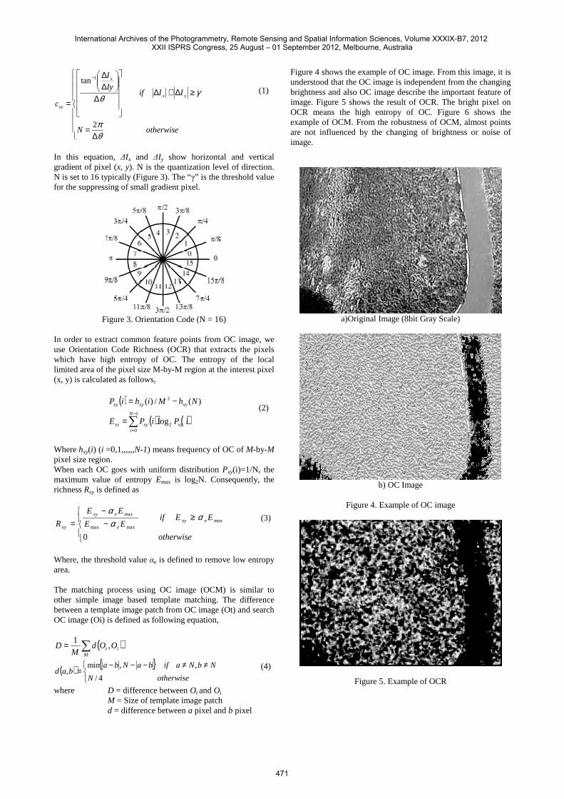
Figure 4 shows the example of OC image. From this image, it is understood that the OC image is independent from the changing brightness and also OC image describe the important feature of image. Figure 5 shows the result of OCR. The bright pixel on OCR means the high entropy of OC. Figure 6 shows the example of OCM. From the robustness of OCM, almost points are not influenced by the changing of brightness or noise of image.
a)Original Image (8bit Gray Scale)
b) OC Image
Figure 4. Example of OC image
Figure 5. Example of OCR
International Archives of the Photogrammetry, Remote Sensing and Spatial Information Sciences, Volume XXXIX-B7, 2012 XXII ISPRS Congress, 25 August – 01 September 2012, Melbourne, Australia
471

Figure 6. Example of OCM
2.4 Robust Common Feature Point Tracking
Figure 7 show the flow of robust tracking procedure of common feature points. At the first, detection of common feature points on first high resolution still image is performed by OCR. The image coordinate of each detected common feature are converted to the image coordinates on synchronized video frame. The tracking of common feature points is performed on video image sequences until the next still image is detected. On the next still image, image coordinates of tracked common feature points are converted to next high resolution still image, and also the detection of common feature points is performed. This procedure is performed until the final still image.
Detection of Common Feature Points on Still Image (OCR)
Matching of Common Feature Point on Video Image
(OCM)
Convert Image Coordinate on Synchronized video frame.
Detection of Outlier in Matching Result (computation of transform
between each frame using LMeds)
Convert Image Coordinate on Still Image.
Sub Pixel Matching on Still Image(LSM)
Next Still Image ?
Final Still Image ?
Candidate of Pass Point
yes
no
yes
no
Figure 7. Flow of Robust Tracking Procedure
The matching of common feature points between each video frame is performed by OCM in this procedure. Therefore, almost points are matched correctly, but generally include some error as outlier in main transformation between each video frames. Therefore, detection of outlier in common feature points is necessary to perform. In this procedure, authors assume that the transformation between each video frame is approximated with affine transformation as following equation,
6541
3211
avauav
avauau
iii
iii
++=++=
+
+ . (5)
Where a1~a6:affine parameter, (u, v):image coordinate at frame i. The affine parameters a1~a6 are calculated using LMedS method and the outlier of matching is eliminated automatically. Finally, in order to perform the sub-pixel matching, Least Square Matching (LSM) of each common feature points on each still image is performed. In this LSM processing, forward and backward matching is performed for the checking of LSM result. This means that the result of forward (e.g. from left image to right image) matching and backward (e.g. from right image to left image) matching has large difference, the matching results of this point is removed as error correspondence. The good results of this sub-pixel matching procedure are used as the candidate of correct pass points in following procedures. 2.5 Tie Point Matching
In order to perform adjusting between each flight line, tie point matching using candidate pass points is performed. Figure 8 shows the flow of tie point matching procedure. At the first, exterior orientation only using candidate pass points is performed. The candidate pass points that have large residual of image coordinate are removed in this step. As the result of this exterior orientation, 3D coordinate of each candidate pass points and exterior orientation parameter for each still image are obtained in arbitrarily position and scale. From this 3D geometry information, the 3D coordinate of each candidate pass point can perform back projection to 2D image coordinate on each still image. Therefore, the tie point matching is performed in the ROI that located around back projection 2D image coordinate of candidate pass points on still image by using LSM. Finally, exterior orientation is computed again using pass points and tie points.
Exterior Orientation using Candidate Pass Points
Set ROI around Back Projection Coordinate
Tie Point Matching by LSM
Exterior Orientation using Pass Points and Tie Points
Figure 8. Tie Point Matching Procedure
International Archives of the Photogrammetry, Remote Sensing and Spatial Information Sciences, Volume XXXIX-B7, 2012 XXII ISPRS Congress, 25 August – 01 September 2012, Melbourne, Australia
472

2.6 Robust Bundle Adjustment in Global Coordinate
As the final step of exterior orientation, we perform bundle adjustment in global coordinate system which using the corresponding points of still image, the GPS observation of UAV at waypoint and the minimum GCP. The candidate pass points and tie points detected automatically as mentioned before generally include mismatching. Also, the GPS observation often includes outlier. Therefore, the bundle adjustment of this investigation is performed using robust regression method based on M-estimator. The M-estimator is defined as the least-square method that the each weighting coefficient is decided to suppress the outlier. Weighting coefficient of M-estimator weff is obtained from following equation.
[ ],/
,)/()(
σψ
vz
wzzweff
=
=
(6) where w: weighting coefficient of least-square method v: residual error of each observation equation σ: RMS of each observation equation. z: normalized residual error ψ: influence function The influence function ψ of this investigation is Tukey’s Biweight that defined as follows.
( )[ ]
≥<−≡
Cz
Czczzz
when 0
when /1)(
22
ψ . (7)
The constant C in equation (7) is selected as 5~9. Therefore, the robust bundle adjustment using M-estimator is performed by minimizing the following error function.
∑
∑∑∑
−+
−+−=
ggg
effg
fff
efff
f pfpfp
efffp
PPw
GGwxxwE
|'|
|'|''''
''' (8)
where xfp: image coordinate of point p on the f-th image x’fp: re-projected image coordinate of point p on the f-th image Gf’: 3-D coordinates of GPS at the f’ -th waypoint G’f’: Computed 3-D coordinates of GPS at the f’ -th waypoint Pg: 3-Dcoordintaes at the g-th GCP. P’g: Computed 3-Dcoordintaes at the g-th GCP. wfp
eff: Weighting coefficient of M-estimator for re-projection error wf’
eff: Weighting coefficient of M-estimator for GPS wg’
eff: Weighting coefficient of M-estimator for GCP From this procedure, exterior orientation parameter of each still image and 3D coordinate of each common feature point are obtained in global coordinate system, and also the influence of error observation such as mismatching points or outlier positioning of GPS at waypoint is suppressed by this procedure.
3. EXPERIMENT
In order to evaluate the effectiveness of proposed automatic corresponding point detection method and robust exterior orientation method, some experiments were performed. These experiments performed at the embankment of Arakawa river side located near the TOKYO. The area of interest was about 80m × 40m. In this area, 11 check points for accuracy evaluation were constructed before by VRS-GPS surveying. In this experiment, two kinds of following flights were planned. The first flight type was planed as photography from constant altitude like conventional aerial photogrammetry. The second flight was photography from constant height from the ground surface. 3.1 Constant Altitude Flight
Figure 9 shows the result of the first flight experiment. In this case, 33 still images were acquired by UAV. The height from UAV to ground was changing from about 10m to 20m due to the altitude of this flight was constant. The positioning data of each still image were obtained by DGPS (SBAS) on UAV. From still images, 1029 corresponding points were obtained automatically with our proposed method using video image and still image. The exterior orientation of this experiment was performed by proposed robust bundle adjustment using still image position and only 3 ground control points. The outlier in still image position from GPS observation and miss matched points were suppressed automatically with our proposed robust bundle adjustment. The RMSE of 3D measurement for 11 check points from aerial triangulation in this experiment was 16mm in XY axis and 22 mm in Z axis. Figure 10 shows the 3D texture model which generated from automatic corresponding points. 3.2 Topography Trace Flight
Figure 11 shows the result of second flight. The height from UAV to ground surface was about 15m and UAV flied as trace the topography of embankment. In this case, 33 still images were obtained and 1489 common feature points were obtained automatically. The RMSE of 3D measurement for 11 check points was 20mm in XY axis and 24 mm in Z axis. Figure 12 shows the 3D texture model of second flight.
: common feature points
: computed still image position
: common feature points
: computed still image position Figure 9. Result of First Flight
International Archives of the Photogrammetry, Remote Sensing and Spatial Information Sciences, Volume XXXIX-B7, 2012 XXII ISPRS Congress, 25 August – 01 September 2012, Melbourne, Australia
473

: common feature points
: computed still image position
: common feature points
: computed still image position Figure 10. 3D model of First Flight
: common feature points
: computed still image position
: common feature points
: computed still image position Figure 11. Result of Second Flight
: common feature points
: computed still image position
: common feature points
: computed still image position Figure 12. 3D model of Second Flight
From these experiments, it is confirmed that the proposed automatic corresponding point detection method and robust exterior orientation method have enough ability for automatic aerial triangulation using Low-cost UAV in low altitude photogrammetry.
4. CONCLUSION
In order to perform automatic aerial triangulation using Low-cost UAV in low altitude application field, we propose
automatic corresponding point detection method and robust exterior orientation method in this investigation. The automatic corresponding point detection method of this investigation utilize video image and still image. The video image can observe the movement of common feature points continuously by the robust common feature point tracking method based on OC image processing. Also, the LSM on still image gives fine accuracy image coordinate. Therefore, the automatic corresponding point detection method of this investigation gives many robust corresponding points from conventional features in each still image automatically. On the other hand, the proposed exterior orientation procedure using robust bundle adjustment base on M-estimator have ability to suppress outlier of GPS observation or miss matched corresponding points. Therefore, the exterior orientation parameter and 3D coordinate from this method is obtained in global coordinate system by using not accurate GPS and minimum global control points. However, the estimation of the reliability of proposed method is still not enough. Also, the process speed of proposed method has to be more increased. Moreover, in order to perform more accurate aerial triangulation without using global control points, utilization of RTK-GPS system has to be considered. Therefore, our next motivation will be the development of low altitude automatic aerial triangulation system using UAV that have RTK-GPS.
REFERENCES
Remondino, F. et. al., 2011. UAV photogrammetry for mapping and 3D modeling Current status and future perspectives. International Archives of Photogrammetry, Remote Sensing and Spatial Information Sciences, Vol. 38(1/C22). ISPRS Confernce UAV-g, Zurich, Switzerland T, Anai, N. Fukaya, et. al. 2010. Application of Orientation Code Matching for Structure from Motion. Proceedings of the ISPRS Commission V Mid-Term Symposium. Vol XXXVIII, Part 5. pp33-38 D, G, Lowe. 2004. Distinctive image features from scale-invariant keypoints. International Journal of Computer Vision, 60(2). pp91-110 H. Bay, Andreas Ess, Tinne Tuytelaars, Luc Van Gool, 2008. SURF: Speeded Up Robust Features, Computer Vision and Image Understanding (CVIU), Vol. 110, No. 3, pp. 346--359
International Archives of the Photogrammetry, Remote Sensing and Spatial Information Sciences, Volume XXXIX-B7, 2012 XXII ISPRS Congress, 25 August – 01 September 2012, Melbourne, Australia
474