automatic image completion with structure propagation …arts.buaa.edu.cn/papers/automatic image...
TRANSCRIPT
April 15, 2011 9:26 WSPC/117-IJSEKE - SPI-J111 0218-1940S0218194010005055
AUTOMATIC IMAGE COMPLETION WITH STRUCTUREPROPAGATION AND TEXTURE SYNTHESIS
XIAOWU CHEN∗, BIN ZHOU†, FANG XU and QINPING ZHAO
State Key Laboratory of Virtual Reality Technology and SystemsSchool of Computer Science and Engineering
Beihang University, Beijing, P. R. China∗[email protected]
In this paper, we present a novel automatic image completion solution in a greedy man-ner inspired by a primal sketch representation model. Firstly, an image is divided intostructure (sketchable) components and texture (non-sketchable) components, and themissing structures, such as curves and corners, are predicted by tensor voting. Secondly,the textures along structural sketches are synthesized with the sampled patches of someknown structure components. Then, using the texture completion priorities decided bythe confidence term, data term and distance term, the similar image patches of someknown texture components are found by selecting a point with the maximum priorityon the boundary of hole region. Finally, these image patches inpaint the missing tex-tures of hole region seamlessly through graph cuts. The characteristics of this solutioninclude: (1) introducing the primal sketch representation model to guide completion forvisual consistency; (2) achieving fully automatic completion. The experiments on naturalimages illustrate satisfying image completion results.
Keywords: Image processing; image completion; image inpainting; texture synthesis.
1. Introduction
1.1. Objectives
Every once in a while, we hope to erase something from our daily photographs, suchas a garbage truck right in the middle of charming Beijing National Stadium, anex-boyfriend in a family photo, a political ally in a group portrait who has fallenout of favor. Other times, there is simply missing data in some areas of the images,such as an aged corner of an old photograph, a hole in an image-based 3D recon-struction due to occlusion, a bug on the camera lens. Image completion, also calledimage inpainting, which is a well-know and well-studied topic in computer visionand graphics realm, is the task of filling in or replacing the hole region mentionedin above scenarios with the available information from their surroundings. The aim
†Corresponding author.
April 15, 2011 9:26 WSPC/117-IJSEKE - SPI-J111 0218-1940S0218194010005055
of this task is to ensure that the modification of completed image cannot be per-ceptible. Let Λ be the region of a given input image I and Λu be the region markedto be filled, called the hole (unknown or missing or mask) region. Image completionis to fill in Λu using the information from known region Ψ = Λ − Λu [1, 2].
Based on our observation, the key to image completion issue is to employ asuitable image representation, image prior model and efficient inference algorithm.Thus, the completion process needs a suitable image representation framework toguide the rendering process of hole regions. Most image completion methods treatthe hole region as a Markov Random Field (MRF) and fill it using standard texturesynthesis techniques. Textures can be modeled as a realization of a local and sta-tionary random process. Thus, each pixel of a texture image can be characterizedby a small set of spatially neighboring pixels. However, for a general image, eachpixel cannot simply be predicted from a small set of local neighboring pixels, andwe cannot assume each pixel is independent of the rest of the image. So, to achievevisually consistent results, this paper presents an integrated framework to completeimages based on the primal sketch representation model [3], which guided the imagecompletion process.
1.2. Related work
In the literature, there were generally three main approaches dealing with the imagecompletion issue: structure-based methods, exemplar-based texture synthesis meth-ods, and methods combining texture synthesis and structure reconstruction.
Through representing the image as piecewise continuous functions, the structure-based methods converted the filling of hole region to an estimation process of explicitfunctions. Some structure-based methods, inspired by the partial derivation equa-tion (PDE), tried to diffuse progressively the information from the boundary of holeregion [4–7], and filled in the hole region by propagating linear structures via diffu-sion. Bertalmio et al. [4] first introduced image inpainting, and filled the hole regionby propagating image Laplacians continuously in isophote directions using PDE,which called BSCB algorithm. However, these PDE-based methods often resulted inoversmooth synthesis when the filling pixels are full of texture. Some other structure-based methods based on the variation model, which involved a criterion of regu-larity of the reconstruction. These variational methods [8–13] usually derived theEuler-Lagrange equation for image and solved the implicit equation via Level Set[14] or tensor voting [15] after constructing the extremum of energy function withthe variation model. In [16], a method called Curvature-Driven Diffusions (CDD)was proposed to handle curve structures by incorporating Euler’s elastica. With thetotal variation (TV) algorithm raised by Rudin et al. [7], Chan et al. [8, 9] presenteda TV image inpainting method, which defined a TV image model and its energythrough bounded variation (BV). Thus the method computed the Euler-Lagrangeequation of energy function by variational principle, and solved the equation inthree image channels using Level Set [14], respectively. This method was suitable

April 15, 2011 9:26 WSPC/117-IJSEKE - SPI-J111 0218-1940S0218194010005055
for non-texture noise image. The tensor voting algorithm [15] estimated the miss-ing curves of hole region according to the structural information of existing curves,which kept the continuity in tangent directions, and completed the junctions ofmultiple curves.
These structure-based methods worked at the pixel level, and performed wellfor small or thin gap filling, such as speckles, scratches, and text. However, whenthe hole region is large, blurring artifacts introduced by the diffusion process arenoticeable. On the other hand, PDE based methods interpolated structure partsof image by defusing local operators or minimizing global curve smooth energies,whereas the minimization of variational energies was time-consuming and often gotstack into local minimal. Nevertheless Euler elastica energies only completed curvesof circle shapes but failed at square shapes, and the tensor voting algorithm tookinto account the information in the neighborhood of hole regions and also curvatureinformation, so it implicitly embeds general shape priors in its energy terms.
Texture synthesis, such as FRAME [17, 18], Heeger [19], is very important tocomputer vision and image processing realms. The aim of texture synthesis is tosynthesize the texture with the given sample texture under certain similarity ofstatistical significance. Through finding the pixel sets that have the nearest neigh-borhoods to the source pixel and constructing the conditional probability density,Efros [20] present a non-parametric texture synthesis algorithm based on pixel sam-pling. Considering the time complexity, Liang [21] proposed the texture synthesisalgorithm based on patch (a rectangle area of image) sampling. Inspired by texturesynthesis techniques, another group of approaches performed inpainting based onpure texture synthesis to solve the oversmooth problem of structure-based methods.Amongst these approaches, the exemplar-based methods, such as Criminisi et al.[22, 23], were more effective, which generated new textures by sampling and copy-ing texture patterns from the source [1]. These exemplar-based methods formulatedthe inpainting as a problem of sampling from a non-parametric one dimensionalconditional MRF (FRAME or Gibbs) density, and propagated hole region by copy-and-paste from a single image [20, 22, 23, 1], or a large dataset [24].
Recent exemplar-based methods also incorporated structure information[5, 25, 26, 2]. Several papers have been concerned with the combination of a PDEmodel (or a variational model) for the reconstruction of structure together with agreedy exemplar-based algorithm for the reconstruction of texture. In [5, 2], theinput image was decomposed into texture components and structure componentsand carried out image completion in the two components. The output was the sumof the two completed components. With the user manually drawing structural linesas guidance in hole region, Sun et al. [25] present an interactive system to performexemplar based inpainting along the edges and the rest of hole region, and achievedthe state-of-the-art results.
Most exemplar-based methods mainly took a greedy way to fill the hole region,finding the best patches locally. Contrary to the greedy approaches, some paperspreferred globally approaches [27], which formulated the image completion as
April 15, 2011 9:26 WSPC/117-IJSEKE - SPI-J111 0218-1940S0218194010005055
discrete global optimization problem. The global optimization problem usually canbe solved using belief propagation (BP) [25, 28–30]. A patch transform algorithmwas performed by Cho [28], which modeled the image as higher-order MRF andsolved the MRF using BP with restraint among patches. In [30] image completionwas automatically solved using an efficient BP. Wexlers global optimization algo-rithm [31] can achieve better fusion performance in boundary between hole regionand known region using expectation maximization (EM) like optimization scheme.But it is sensitive to initial solution and easy to get local optimal solution. TheShiftMap algorithm [32] transformed the image completion into a graph labelingproblem, and used graph cuts [33] to obtain global optimization, whose limitationis computational time.
1.3. Contributions
This paper presents a novel automatic image completion solution in a greedy mannerbased on a primal sketch representation model [3], which automatically completessalient structures and texture of the hole region. Firstly, given an input image, itsprimal sketch graph is computed using the primal sketch representation model [3],and the given image is divided into structure (sketchable) components and texture(non-sketchable) components. Afterwards, 3-degree-junctions such as T-junctions,Y-junctions around the hole region are detected by Wu’s algorithm [34]. Secondly,based on testing the compatibility between any two terminators of the 3-degree-junctions with Elastica [35], the missing structures, such as curves and corners, arepredicted by tensor voting [36], and the structural sketch completion is completed.Thirdly, the textures along structural sketches are synthesized with the optimal sam-pled patches of some known structure components, which are computed by BeliefPropagation algorithm [37]. The filled textures along structural sketches can guidethe texture synthesis process of the remaining hole region. Fourthly, after structurecompletion, using the texture completion priorities decided by the confidence term,data term and distance term, the similar image patches of some known texture com-ponents are found by selecting a point with the maximum priority on the boundaryof hole region. Finally, these image patches inpaint the remaining missing textures ofhole region seamlessly through exemplar-based texture synthesis. Instead of copy-ing the whole selected patch [23], the proposed solution only pastes an optimalportion of a patch to the hole region, and the optimal seam is determined by graphcuts algorithm [38]. The characteristics of this solution include: (1) introducing theprimal sketch representation model to guide completion for visual consistency; (2)achieving fully automatic completion. The experiments on natural images illustratesatisfying image completion results and show above characteristics.
1.4. Organization
The remainder of this paper is organized as following. Section 2 formulates theimage completion and introduces the overall framework of our solution. Sections 3
April 15, 2011 9:26 WSPC/117-IJSEKE - SPI-J111 0218-1940S0218194010005055
and 4 present the detailed framework implementation of our solution from structurecompletion and texture completion aspects. Experiment results and conclusions areshown in Secs. 5 and 6, respectively.
2. Formulation and Framework Overview
2.1. Problem formulation
Given an image defined on lattice Λ with hole region Λu, the goal of image comple-tion is to infer an idea image I based on the partial observation Io|Λ\Λu
.According to Bayesian framework, image completion can be defined as maximize
the posterior probability of p(I|Io, Λ):
p(I|Io, Λ) =p(Io|I, Λ)p(I, Λ)
p(Io, Λ)∝ p(Io|I, Λ)p(I, Λ). (1)
Essentially, the key to the image completion issue is to employ a suitable imageprior model p(I, Λ) or define a set of energy functions which are the logarithmlikelihood functions of the posterior probability p(I|Io, Λ). This paper adopts theprimal sketch model [3] as image prior, which is defined as follows:
p(I, S) =1Z
exp
−
n∑i=1
∑(x,y)∈Λstr,i
12σ2
(I(x, y) − Bi(x, y|θi))2 − γstr(Sstr)
−m∑
j=1
∑(x,y)∈Λtex,j
K∑k=1
φj,k(Fk ∗ I(x, y)) − γtex(Stex)
, (2)
where S is a set of pixels of discontinuity regions of given image which contains Sstr
and Stex, Bi(x, y|θi), i = 1, . . . , n is a set of sparse coding functions representing edgeand ridge segments Λstr in the image, θi are geometric and photometric parametersof these coding functions, and Fk, k = 1, . . . , K are texture filters applied on thepixels in Λtex.
The computed primal sketch graph divides the image lattice into structuredomain Sstr and texture domain Stex, respectively. Image intensities on the struc-ture domain Sstr are represented by sparse coding functions with explicit geometricparameters (such as normal directions) and photometric parameters. These param-eters provide prior information for structure completion of the image completionprocess. The MRF model is assumed to model image intensities on the texturedomain Stex, and the texture completion can be achieved by finding similar neigh-borhoods and synthesizing the missing pixels.
The energy function E(X) is defined for searching optimal image patches fromknown regions to fill the structure and texture components of the hole region. Theoptimal sampled labels X = xiL
i=1 are obtained by minimizing E(X):
E(X) = Estructure + Etexture, (3)
April 15, 2011 9:26 WSPC/117-IJSEKE - SPI-J111 0218-1940S0218194010005055
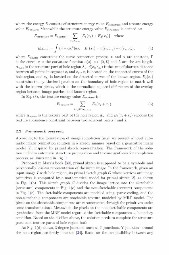
where the energy E consists of structure energy value Estructure and texture energyvalue Etexture, Meanwhile the structure energy value Estructure is defined as:
Estructure = Eelastic +∑
i∈Λu,sk
E1(xi) + E2(xi) where
Eelastic =∫
Γ
(ν + ακ2)ds, E1(xi) = d(ci, cxi) + d(cxi , ci), (4)
where Eelastic constrains the curve connection process, ν and α are constant, Γis the curve, κ is the curvature function κ(s), s ∈ [0, L] and L are the arc-length.Λu,sk is the structure part of hole region Λu. d(ci, cxi) is the sum of shortest distancebetween all points in segment ci and cxi . ci is located on the connected curves of thehole region, and cxi is located on the detected curves of the known region. E2(xi)constrains the synthesized patches on the boundary of hole region to match wellwith the known pixels, which is the normalized squared differences of the overlapregion between image patches and known region.
In Eq. (3), the texture energy value Etexture is:
Etexture =∑
(i,j)∈Λu,nsk
E3(xi + xj), (5)
where Λu,nsk is the texture part of the hole region Λu, and E3(xi + xj) encodes thetexture consistence constraint between two adjacent pixels i and j.
2.2. Framework overview
According to the formulation of image completion issue, we present a novel auto-matic image completion solution in a greedy manner based on a generative imagemodel [2], inspired by primal sketch representation. The framework of the solu-tion includes automatic structure propagation and texture synthesis for completionprocess, as illustrated in Fig. 1.
Proposed in Marr’s book [39], primal sketch is supposed to be a symbolic andperceptually lossless representation of the input image. In the framework, given aninput image I with hole region, its primal sketch graph G whose vertices are imageprimitives is computed by a mathematical model for primal sketch [3], as shownin Fig. 1(b). This sketch graph G divides the image lattice into the sketchable(structure) components in Fig. 1(c) and the non-sketchable (texture) componentsin Fig. 1(e). The sketchable components are modeled using sparse coding, and thenon-sketchable components are stochastic texture modeled by MRF model. Thepixels on the sketchable components are reconstructed through the primitives undersome transformations. Meanwhile the pixels on the non-sketchable components aresynthesized from the MRF model regarded the sketchable components as boundarycondition. Based on the division above, the solution needs to complete the structureparts and texture parts of hole region both.
As Fig. 1(d) shows, 3-degree-junctions such as T-junctions, Y-junctions aroundthe hole region are firstly detected [34]. Based on the compatibility between any
April 15, 2011 9:26 WSPC/117-IJSEKE - SPI-J111 0218-1940S0218194010005055
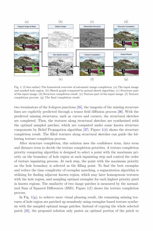
Fig. 1: (Color online) The framework overview of automatic image completion. (a) The input imageand marked hole region. (b) Sketch graph computed by primal sketch algorithm. (c) Structure partof the input image. (d) Structure completion result. (e) Texture part of the input image. (f) Texturecompletion process. (g) The final completion result.
two terminators of the 3-degree-junctions [35], the tangents of the missing structurelines are explicitly predicted through a tensor field diffusion process [36]. With thepredicted missing structures, such as curves and corners, the structural sketchesare completed. Then, the textures along structural sketches are synthesized withthe optimal sampled patches, which are computed under some known structurecomponents by Belief Propagation algorithm [37]. Figure 1(d) shows the structurecompletion result. The filled textures along structural sketches can guide the fol-lowing texture completion process.
After structure completion, this solution uses the confidence term, data termand distance term to decide the texture completion priorities. A texture completionpriority computing algorithm is designed to select a point with the maximum pri-ority on the boundary of hole region at each inpainting step and control the orderof texture inpainting process. At each step, the point with the maximum priorityon the hole boundary is selected as the filling point. To find the best exemplarand reduce the time complexity of exemplar matching, a segmentation algorithm isutilizing for finding adjacent known region, which may have homogenous textureswith the hole region, and sampling optimal exemplar for each highest priority pixelin known regions. The similarity of two image patches is measured by the normal-ized Sum of Squared Differences (SSD). Figure 1(f) shows the texture completionprocess.
In Fig. 1(g), to achieve more visual pleasing result, the remaining missing tex-tures of hole region are patched up seamlessly using exemplar-based texture synthe-sis with the sampled optimal image patches. Instead of copying the whole selectedpatch [23], the proposed solution only pastes an optimal portion of the patch to

April 15, 2011 9:26 WSPC/117-IJSEKE - SPI-J111 0218-1940S0218194010005055
the hole region, and the optimal seam is determined by graph cuts algorithm [38].Figure 1(g) shows the final completion result.
The implementation of the framework needs to complete the missing structureparts, and then synthesis the texture parts of the hole region. Thus, structure com-pletion and texture completion, two essential aspects of the framework, are describedin the following sections in detail (Secs. 3 and 4).
3. Structure Completion
3.1. Structure sketch completion
Structure sketch detection. On the basis of primal sketch division, the edges ofthe input image are detected using gPb algorithm [37]. As the gPb produces proposaledge map only, the structure information are obtained by tracing the map usingCanny’s hysteresis thresholding. With the result of edge detection, the solution findslong continuous sketches (curves) around the hole region automatically. 3-degree-junctions of the sketches (curves) and the boundary of the hole region are detectedby Wu’s algorithm [34], as illustrated in Fig. 2(a).
Structure sketch matching. As illustrated in Fig. 2(b), 3-degree-junctions arebroken into a set of terminators as open bonds. These open bonds need to finda match by testing compatibilities between any two terminators on appearancecues and geometric properties. Given two terminators ai and aj , the contour to becompleted between them, denoted by Γ∗, is decided by minimizing the Elastica costfunction (as shown in Eq. (6)) in a contour space ΩΓ [35]:
Γ∗ = arg minΓ∈ΩΓ
∫Γ
[(v1 + α1κ21) + (v2 + α2κ
22)]ds, (6)
where κ1 is the curvature of a1, κ2 is the curvature of a2, v1 and v2 are constants,α1 and α2 are scalable coefficients.
(a) (b) (c)
Fig. 2: (Color online) Structure sketch completion. (a) 3-degree-junctions (such as T-junctions,Y-junctions) of long continuous sketches and the boundary of the hole region. (b) Terminators.(c) Curve connection.

April 15, 2011 9:26 WSPC/117-IJSEKE - SPI-J111 0218-1940S0218194010005055
Tensor voting. After deciding the terminators matches, this solution predicts themissing structures, such as curves and corners, by tensor voting. Firstly, the tan-gents (normal directions) of every existing curve points are calculated using linearregression and least square method according to Eq. (7).
Y = kX + b
k =∑
(X − X)(Y − Y )∑(X − X)2
=lXY
lXX=
∑XY − (
PX)(
PY )
n∑X2 − (
PX)2
n
, b = Y − kX, (7)
where k is the coefficient of regression, b is the intercept, and n is the number ofsampled points in the existing curve.
Secondly, these points with the normal directions are represented as 2D sticktensors [36, 15] according to Eq. (8).
T = λ1e1eT1 + λ2e2e
T2 = (λ1 − λ2)e1e
T1 + λ2(e1e
T1 + e2e
T2 ), (8)
where the tensor T is a 2-by-2 matrix, λ1, λ2 are the eigenvalues and λ1 > λ2 > 0,e1, e2 are the eigenvectors, λ1 − λ2 defines the saliency or certainty of curve. Inthis solution: λ1 = 1, λ2 = 0, e2 = 0, and e1 is normal vector of the point on theexisting curve.
Thirdly, the existing curve points, called voters, can vote a saliency for thereceivers which are the other points of the input image. The saliency affects thenormal direction of the receiver. The saliency decay function has the following form(Eq. (9)):
DF (s, κ, σ) = e−s2+cκ2
σ2 , (9)
where s is the arc length of the osculating circle between the receiver and voter,κ is the curvature, c controls the degree of decay with curvature, σ is the scale ofvoting, which determines the effective neighborhood size. Given a voter, the localtensor voting field is calculated with its 2D stick tensors according to Eq. (9), andthe neighbor points in the scale of voting receive a direction effect and an energyeffect. The direction effect is determined by the line between the voter and receiver.The energy effect defines the saliency or certainty in the direction effect. The localtensor voting fields are as shown in Fig. 3, where σ = 54, the neighborhood size is2 × 54 + 1 = 109, and the colors changing from red to blue illustrate the saliencyenergy value from high to low.
Finally, according to the local tensor voting fields, each point in the hole region(blue point in Fig. 4) obtains a curve saliency value λ1–λ2 after receiving andaccumulating the collected votes from the existing curve points (voters) in theknown regions of the image. The tensor voting process is illustrated in Fig. 4. Thesaliency map in the hole region is formed with the accumulation of curve saliencyvalues.
Non-maxima suppression. Finding the local maximum in the curve saliency mapmay allow us to figure out the best curve while using the surrounding context of

April 15, 2011 9:26 WSPC/117-IJSEKE - SPI-J111 0218-1940S0218194010005055
Fig. 3: (Color online) The local tensor voting fields of four directions, where σ = 54, and theneighborhood size is 109. The center point of each figure is the voter, and the other points arereceivers. The colors changing from red to blue illustrate the saliency energy value from high tolow.
Fig. 4: (Color online) Curve connection by tensor voting. The black lines are existing curves inknown regions, and each point plays the role of voters. The rectangle demonstrates the boundaryof hole region, and the blue points are receivers. The saliency map of hole region is achieved withthe accumulation of curve saliency value of blue points.
each pixel to determine whether or not the curve passes there. The process of takingthe maximum in the normal direction first identifies the normal axis for each tensorpoint in the image. Once it is done, the likelihoods are checked along the sides of thecurrent pixel to see if it is in fact a maximum. We apply a local maxima algorithm

April 15, 2011 9:26 WSPC/117-IJSEKE - SPI-J111 0218-1940S0218194010005055
saliency mapthe missing curve completed curve
Fig. 5: (Color online) The non-maxima suppression during curve connection by tensor voting.With the saliency map, the points with the highest curve saliency are selected as the curve pointsfor the missing curve.
in local area on the salience map to identify edges of the hole region. So, For eachposition xi, only the point with the highest curve saliency is selected as the curvepoint Pxi :
Pxi = maxPxi,yj(λ1 − λ2), 1 ≤ j ≤ S, (10)
where xi, yi is the image coordinates, S is the sample density (in pixels). The resultof structural sketch completion with non-maxima suppression is illustrated in Fig. 5and Fig. 2(c).
3.2. Structure texture completion
To complete the textures along structural sketches, a Belief Propagation algorithmsimilar to Sun [25, 37] is employed, which finds the optimal labels for each sampledpoint on the connected curves by minimizing the energy Estructure in Eq. (4), asillustrated in Fig. 6. The filled textures along structural sketches can guide thefollowing texture completion process of the remaining hole region.
Fig. 6: (Color online) Synthesize textures along structural sketches using Belief Propagation. Thewhite rectangle demonstrates the hole region, and the orange red points are the sampled points onthe connected curve. The blue patches are sampled along the existing curves by Belief Propagation.

April 15, 2011 9:26 WSPC/117-IJSEKE - SPI-J111 0218-1940S0218194010005055
4. Texture Completion
After structure completion, there are still large hole regions to be filled. The equiva-lence of the Julesz ensemble and FRAME model [17, 18] states that texture synthesiscan be done without necessarily learning MRF model. We adopt this strategy andsample from a subset of the Julesz ensemble by pasting texture patches from thesampled texture (exemplars).
To achieve more visual pleasing result, the textures of the remaining hole regionare filled by the graph cuts texture synthesis algorithm [38]. Before applying thegraph cuts based texture synthesis to image completion issue, this solution usesthe confidence term, data term and distance term to decide the texture completionpriorities. Then a texture completion priority computing algorithm is designed toselect a point with the maximum priority on the boundary of hole region at eachinpainting step and control the order of texture inpainting process. At each step,the point with the maximum priority on the hole boundary is selected as the fillingpoint.
To find the best exemplar and reduce the time complexity of exemplar matching,this solution runs a segmentation algorithm to find adjacent known region whichmay have homogenous textures around the hole region, and samples optimal exem-plar for each highest priority pixel in known regions. The similarity of two imagepatches is measured by the normalized Sum of Squared Differences (SSD).
With the sampled optimal image patches, the remaining textures of hole regionare patched up seamlessly using exemplar-based texture synthesis. Instead of copy-ing the whole selected patch [23], the proposed solution only pastes an optimalportion of a patch to the hole region, and the optimal seam is determined by graphcuts algorithm [38].
4.1. Completion priority
Filling order is crucial to a greedy texture completion method. Thus far, the defaultfavorite was proposed by Criminisi [22], where the completion priority is decidedthe confidence term and data term. This solution further constrains the completionpriority by adding a distance term to ensure that hole region is filled from theoutside inward.
After some filling step, some hole regions remain unknown while other holeregions have been inpainted. It is needed to find a filling point with the maximumpriority, and the priority is decided by the confidence term, data term and distanceterm. The distance term is calculated using Felzenszwalb’s distance transform algo-rithm [40]. The original boundary of hole region has the distance energy of 0, andother pixels have distance energy greater than 0.
This solution performs above task through a best-first filling algorithm thatdepends entirely on the priority values that are assigned to each patch on the fillfront. The priority computation is biased toward those patches which are on the

April 15, 2011 9:26 WSPC/117-IJSEKE - SPI-J111 0218-1940S0218194010005055
continuation of strong edges, surrounded by high-confidence pixels and nearer tothe boundary of hole region. For the pixel p located on the boundary of hole regionΩ, Ψp is the image domain centered at the point p, and some parts of Ψp is knownwhile the others not.
P (p) = C(p)D(p)Dt(p) where C(p) =Σq∈Ψp∩(I−Ω)C(q)
|Ψp| , D(p) =|∇I⊥p · np|
α,
(11)
where the priority P (p) at p is the product of C(p), D(p) and Dt(p) together.C(p) and D(p) are the confidence term and the data term, respectively. Dt(p) isthe distance term. I defines the input image with hole region Ω. p is located onthe boundary of hole region Ω. Ψp is the image domain centered at the point p.q is a point in the Ψp. Confidence term C(p) may be thought of as a measure ofthe amount of reliable information surrounding p. ∇I⊥p is a vector of isophotes.np is a unit vector orthogonal to the boundary at point p. Data term D(p) is afunction of the strength of isophotes hitting the boundary at each iteration. Distanceterm Dt(p) is calculated using Felzenszwalb’s distance transform algorithm [40],which ensure that pixels nearer to the original hole boundary are filled with higherpriority.
4.2. Graph cuts texture synthesis
To achieve more visual pleasing result, the textures of the remaining hole regions arefilled by the graph cuts texture synthesis algorithm [38]. First we adopt the graphcuts segmentation algorithm of Felzenszwalb [40] with the parameters sigma = 0.5,k = 500, min = 20. This can often group homogenous regions of an image together,and produce reasonable oversegmentations with fewer superpixels (typically lessthan 100 for a 800 × 600 image). Hole region is always adjacent to some knownregions, and these adjacent regions form a region adjacent graph. The proposedsolution only needs to search in these adjacent regions for best image patchesto synthesis the texture of the remaining hole regions. This search strategy canimprove the reliability and efficiency of texture synthesis of the remaining holeregions.
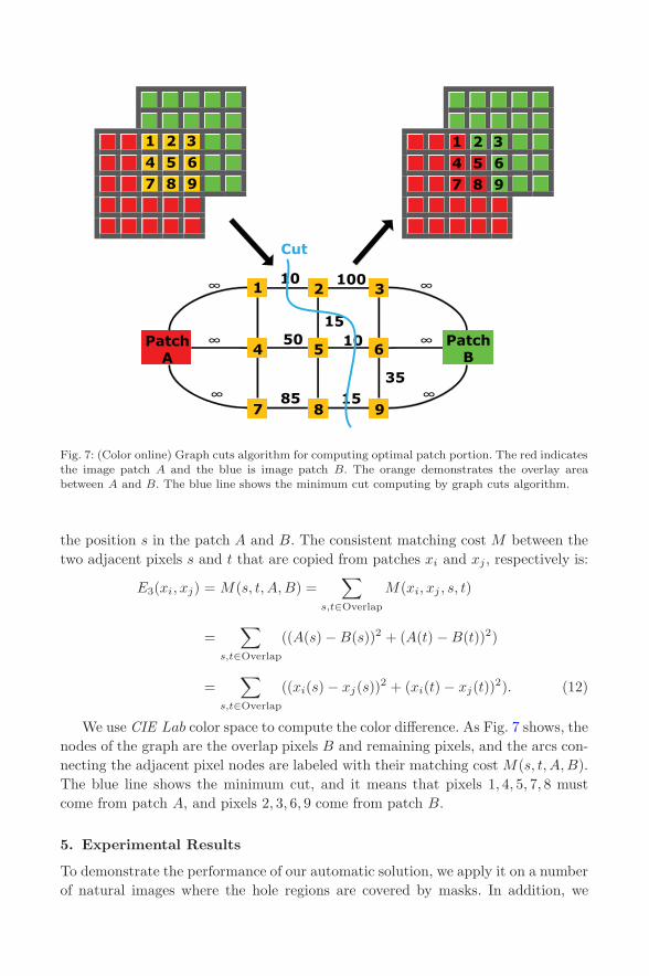
To synthesis the textures of remaining hole regions, this solution samples optimalpatch for each highest priority pixel in known regions. The similarity of two imagepatches is measured by the normalized Sum of Squared Differences (SSD). UnlikeCriminisi et al. [22], which copy the whole patch to the hole region at a time, weonly copy an optimal portion of the patch. The portion of the patch to be copiedis determined by graph cuts texture synthesis algorithm of Kwatra [38]. It usuallyproduces more visually pleasing results than copying and pasting directly. Let s andt be two adjacent pixels in the overlap region between two adjacent image patchesA (or xi) and B (or xj). Let A(s) (or xi(s)) and B(s) (or xj(s)) be the colors at
April 15, 2011 9:26 WSPC/117-IJSEKE - SPI-J111 0218-1940S0218194010005055
Fig. 7: (Color online) Graph cuts algorithm for computing optimal patch portion. The red indicatesthe image patch A and the blue is image patch B. The orange demonstrates the overlay areabetween A and B. The blue line shows the minimum cut computing by graph cuts algorithm.
the position s in the patch A and B. The consistent matching cost M between thetwo adjacent pixels s and t that are copied from patches xi and xj , respectively is:
E3(xi, xj) = M(s, t, A, B) =∑
s,t∈Overlap
M(xi, xj , s, t)
=∑
s,t∈Overlap
((A(s) − B(s))2 + (A(t) − B(t))2)
=∑
s,t∈Overlap
((xi(s) − xj(s))2 + (xi(t) − xj(t))2). (12)
We use CIE Lab color space to compute the color difference. As Fig. 7 shows, thenodes of the graph are the overlap pixels B and remaining pixels, and the arcs con-necting the adjacent pixel nodes are labeled with their matching cost M(s, t, A, B).The blue line shows the minimum cut, and it means that pixels 1, 4, 5, 7, 8 mustcome from patch A, and pixels 2, 3, 6, 9 come from patch B.
5. Experimental Results
To demonstrate the performance of our automatic solution, we apply it on a numberof natural images where the hole regions are covered by masks. In addition, we

April 15, 2011 9:26 WSPC/117-IJSEKE - SPI-J111 0218-1940S0218194010005055
Fig. 8: (Color online) Some typical results of automatic image completion. The first two columnsshow the input images and marked hole regions. The third column shows the results of automaticstructure completion. The last column shows the final results. Better to view on screen.
compare our automatic solution to Criminisi’s method [23], which is a greedy imagecompletion method and similar to ours. We do not compare with [25]since it needsmanually added structure information.
Figure 8 shows a few representative results by the proposed solution. The firsttwo columns show the input images and marked hole regions. The third columnshows the results of automatic structure completion. The last column shows thefinal results. As shown in Fig. 8, our automatic greedy solution can produce visuallynatural results without obvious artifacts. Both structures (such as stairs and thehorizons) and textures (such as the sea, roadway and tree) are handled very well inthe images with satisfying visual consistency.
Figure 9 gives the comparative results on three example images, where we wantto erase some objects for example something in the river, the unpopular peoplebesides the parterre, two girls standing on the bridge. The first column showsthe original images. The second column shows the results obtained by the greedy

April 15, 2011 9:26 WSPC/117-IJSEKE - SPI-J111 0218-1940S0218194010005055
Fig. 9: (Color online) Comparison of our image completion results and Criminisis. The first columnshows the original images. The second column is the results of Criminisis algorithm. The thirdcolumn shows the results of our solution. Better to view on screen.
algorithm in [23]. From these results, we can find some obvious artifacts, and more-over some strong structures (such as the corner of the parterre) cannot be propa-gated well. The last column is the results of our automatic solution. We successfullypropagate the structure and synthesize the texture.
More completion results are provided in Figs. 10 and 11. All these results illus-trate the satisfying completion and the characteristics of our solution.

April 15, 2011 9:26 WSPC/117-IJSEKE - SPI-J111 0218-1940S0218194010005055
Fig. 10: (Color online) More image completion results where we want to remove the objects, suchas the outland players in a baseball match, the front-runner in an athletics game, and the visualinconsistent girl, from the input images. The first column shows the original images. The secondcolumn is the results of our automatic solution.

April 15, 2011 9:26 WSPC/117-IJSEKE - SPI-J111 0218-1940S0218194010005055
Fig. 11: (Color online) Another image completion results. The laggard on the battlefield, the zebrabursting on the scene and the tourists photographed accidentally would be erased from the threeinput images. The first column shows the original images. The second column is the results of ourautomatic solution.
April 15, 2011 9:26 WSPC/117-IJSEKE - SPI-J111 0218-1940S0218194010005055
6. Conclusion and Future Works
This paper has presented a novel automatic image completion solution that auto-matically fills structure and texture components inspired by on primal sketch model.Firstly, an image is divided into structure components and texture components, andthis solution predicts the missing structures, such as curves and corners, by ten-sor voting. Secondly, the textures along structural sketches are synthesized with thesampled patches of some known structure components. Then, with the texture com-pletion priorities decided by the confidence term, data term and distance term, thesimilar image patches of some known texture components are found by selecting apoint with the maximum priority on the boundary of hole region. Finally, this solu-tion patches up the remaining textures of hole region seamlessly with these imagepatches using graph cuts algorithm. Experiment results on the natural images showour characteristics.
However, this solution is still in the preliminary research stage. Nearly 90%time is spending on similar image patches searching, and common image patchessearching method such as Sum of Squared Differences (SSD) is computationally-insensitive. It is considerable to choose histogram features as the descriptor of thesampled image patches and apply a nearest neighbor search method, such as kd-tree,for accelerative exemplar matching. On the other hand, although most image com-pletion methods are based on a greedy strategy, we also seek to explore the appealingglobal solutions.
Acknowledgements
This work was partially supported by National Natural Science Foundation ofChina (90818003&60933006), National High Technology (863) and Key Technol-ogy R&D Program of China (2009AA01Z331&2008BAH29B02), and SpecializedResearch Fund for the Doctoral Program of Higher Education (20091102110019).We would like to thank Dr. Liang Lin for helpful suggestions, and Kai Jiang fordata processing.
References
1. H. Ting, S. Chen, J. Liu and X. Tang, Image inpainting by global structure andtexture propagation, in ACM International Conference on Multimedia (ACM, 2007),pp. 517–520.
2. X. Chen and F. Xu, Automatic image inpainting by heuristic texture and struc-ture completion, International Conference on MultiMedia Modeling, Vol. 5916, 2010,pp. 110–119.
3. C. E. Guo, S. C. Zhu and Y. N. Wu, Primal sketch: Integrating texture and structure,Computer Vision and Image Understanding 106(1) (2007) 5–19.
4. M. Bertalmio, G. Sapiro, V. Caselles and C. Ballester, Image inpainting, in Interna-tional Conference on Computer Graphics and Interactive Techniques (SIGGRAPH)(ACM, 2000), pp. 417–424.

April 15, 2011 9:26 WSPC/117-IJSEKE - SPI-J111 0218-1940S0218194010005055
5. M. Bertalmio, L. Vese, G. Sapiro and S. Osher, Simultaneous structure and textureimage inpainting, in IEEE Conference on Computer Vision and Pattern Recognition2 (2003) II–707–II–12.
6. F. Bornemann and T. Marz, Fast image inpainting based on coherence transport,Journal of Mathematical Imaging and Vision 28(3) (2007) 259–278.
7. L. I. Rudin, S. Osher and E. Fatemi, Nonlinear total variation based noise removalalgorithms, Physica D 60 (1992) 259–268.
8. T. F. Chan, S. H. Kang and J. Shen, Euler’s elastica and curvature-based inpainting,SIAM J. Appl. Math. 63(2) (2003) 564–592.
9. T. F. Chan and J. Shen, Mathematical models for local deterministic inpaintings,SIAM J. Appl. Math. 62(3) (2001) 1019–1043.
10. S. Esedoglu and J. H. Shen, Digital inpainting based on the mumford-shah-euler imagemodel, European J. Appl. Math. 13 (2002) 353–370.
11. M. Nitzberg, D. Mumford and T. Shiota, Filtering, segmentation, and depth, LectureNotes in Computer Science, Vol. 662 (Springer, Berlin, 1993).
12. S. Masnou, Disocclusion: A variational approach using level lines, IEEE Trans. ImageProcessing 11(2) (2002) 68–76.
13. S. Masnou and J. M. Morel, Level lines based disocclusion, in International Conferenceon Image Processing, Vol. 3 (1998), pp. 259–263.
14. S. Osher and J. A. Sethian, Fronts propagating with curvature-dependent speed: Algo-rithms based on hamilton-jacobi formulations, J. Computational Physics 79(1) (1988)12–49.
15. P. Mordohai, A Perceptual Organization Approach for Figure Completion, Binocularand Multiple-View Stereo and Machine Learning using Tensor Voting, Ph.D. thesis,University of Southern California (2005).
16. T. F. Chan and J. Shen, Nontexture inpainting by curvature-driven diffusions,J. Visual Communication and Image Representation 12(4) (2001) 436–449.
17. S. C. Zhu, Y. Wu and D. Mumford, Filters, random fields and maximum entropy(frame): Towards a unified theory for texture modeling, International Journal ofComputer Vision 27(2) (1998) 107–126.
18. Y. N. Wu, S. C. Zhu and X. Liu, Equivalence of julesz ensembles and frame models,Int. J. Computer Vision 38(3) (2000) 247–265.
19. D. J. Heeger and J. R. Bergen, Pyramid-based texture analysis/synthesis, in Interna-tional Conference on Computer Graphics and Interactive Techniques (SIGGRAPH)(ACM, 1995), pp. 229–238.
20. A. A. Efros and T. K. Leung, Texture synthesis by non-parametric sampling, in IEEEInternational Conference on Computer Vision 2 (1999) 1033–1038.
21. L. Liang, C. Liu, Y. Q. Xu, B. Guo and H. Y. Shum, Real-time texture synthesis bypatch-based sampling, ACM Trans. Graphics 20(3) (2001) 127–150.
22. A. Criminisi, P. Perez and K. Toyama, Object removal by exemplar-based inpaint-ing, IEEE Conference on Computer Vision and Pattern Recognition 2 (2003)II–721–II–728.
23. A. Criminisi, P. Perez and K. Toyama, Region filling and object removal by exemplar-based image inpainting, IEEE Transactions on Image Processing 13(9) (2004)1200–1212.
24. J. Hays and A. A. Efros, Scene completion using millions of photographs, ACM Trans.Graphics 26(3) (2007) 4.
25. J. Sun, L. Yuan, J. Jia and H. Y. Shum, Image completion with structure propagation,ACM Trans. Graphics 24(3) (2005) 861–868.
26. F. Cao, Y. Gousseau, S. Masnou and P. Prez, Geometrically guided exemplar-basedinpainting, preprint (2009).
April 15, 2011 9:26 WSPC/117-IJSEKE - SPI-J111 0218-1940S0218194010005055
27. N. Komodakis, Image completion using global optimization, in IEEE Conference onComputer Vision and Pattern Recognition (2006), pp. 442–452.
28. T. S. Cho, M. Butman, S. Avidan and W. T. Freeman, The patch transform and itsapplications to image editing, in IEEE Conference on Computer Vision and PatternRecognition (2008), pp. 1–8.
29. W. T. Freeman, E. C. Pasztor and O. T. Carmichael, Learning low-level vision, Int.J. Computer Vision 40(1) (2000) 25–47.
30. N. Komodakis and G. Tziritas, Image completion using efficient belief propagationvia priority scheduling and dynamic pruning, IEEE Trans. Image Processing 16(11)(2007) 2649–2661.
31. Y. Wexler, E. Shechtman and M. Irani, Space-time completion of video, IEEE Trans-actions on Pattern Analysis and Machine Intelligence 29(3) (2007) 463–476.
32. Y. Pritch, E. Kav-Venaki and S. Peleg, Shift-map image editing, in IEEE InternationalConference on Computer Vision (2009), pp. 151–158.
33. Y. Boykov, O. Veksler and R. Zabih, Fast approximate energy minimization via graphcuts, IEEE Transactions on Pattern Analysis and Machine Intelligence 23(11) (2001)1222–1239.
34. T. F. Wu, G. S. Xia and S. C. Zhu, Compositional boosting for computing hierarchicalimage structures, in IEEE Conference on Computer Vision and Pattern Recognition(2007), pp. 1–8.
35. D. Mumford and J. Shah, Optimal approximations by piecewise smooth functions andassociated variational problems, Commun. Pure and Applied Mathematics XLII(5)(1989) 577–685.
36. G. Medioni, M. S. Lee and C. K. Tang, A computational framework for segmentationand grouping: Tensor analysis, in A Computational Framework for Segmentation andGrouping (Elsevier Science, Amsterdam, 2000), pp. 219–224.
37. J. Y. Broadway, J. S. Yedidia, W. T. Freeman and Y. Weiss, Generalized belief prop-agation, in Neural Information Processing Systems Conference (MIT Press, 2000),pp. 689–695.
38. V. Kwatra, A. S. Dl, I. Essa, G. Turk and A. Bobick, Graphcut textures: Image andvideo synthesis using graph cuts, ACM Trans. Graphics (SIGGRAPH) 22(3) (2003)277–286.
39. D. Marr, Vision: A computational investigation into the human representation andprocessing of visual information (W. H. Freeman, San Francisco & New York, 1982).
40. P. Felzenszwalb and D. Huttenlocher, Efficient graph-based image segmentation, Int.J. Computer Vision 59(2) (2004) 167–181.