automatic planer - 15” - harbor freight...
TRANSCRIPT

AUTOMATIC PLANER - 15”Model 97040
SET UP ANd OPERATINg INSTRUCTIONS
Diagrams within this manual may not be drawn proportionally.
Due to continuing improvements, actual product may differ slightly from the product described herein.
distributed exclusively by Harbor Freight Tools®.3491 Mission Oaks Blvd., Camarillo, CA 93011
Visit our website at: http://www.harborfreight.com
Read this material before using this product. Failure to do so can result in serious injury. SAVE THIS MANUAL.
Copyright© 2007 by Harbor Freight Tools®. All rights reserved. No portion of this manual or any artwork contained herein may be reproduced in any shape or form without the express written consent of Harbor Freight Tools.
For technical questions or replacement parts, please call 1-800-444-3353.

Page 2SKU 97040 For technical questions, please call 1-800-444-3353.
CONTENTSIMPORTANT SAFETY
INFORMATION ........................... 3
gENERAL SAFETY RULES ......... 4
SPECIFIC SAFETY RULES .......... 6
gROUNdINg ................................ 7ExTENSION CORdS ........................ 7SYMbOLOgY .................................... 8
SPECIFICATIONS ......................... 9
UNPACkINg ................................. 9
SET UP INSTRUCTIONS .............. 9CLEANINg ........................................ 9ASSEMbLINg THE LIFT
HANdLES ..................................... 10ASSEMbLINg THE UPPER
ROLLERS ..................................... 11LIFTINg THE PLANER ................... 11ATTACHINg THE TAbLE
ExTENSIONS ............................... 12ATTACHINg A POwER PLUg ....... 12TO ATTACH A dUST
ExTRACTION HOSE .................... 13
PLANER AdJUSTMENTS .......... 13dEPTH OF CUT AdJUSTMENTS ... 13SPEEd CONTROL AdJUSTMENTS 14LOCkINg THE TAbLE .................... 14bELT TENSION AdJUSTMENTS ... 15AdJUSTINg ANd REPLACINg
kNIVES ......................................... 16AdJUSTINg THE ROLLER
SPRINg TENSION ........................ 17AdJUSTINg CUTTERHEAd
PARALLEL TO TAbLE ................. 18
THE CHIP bREAkER ...................... 20TAbLE ROLLER AdJUSTMENTS .21
bASIC OPERATINg INSTRUCTIONS ....................... 21
MAINTENANCE ANd SERVICINg .............................. 24
TROUbLESHOOTINg ..................... 24
PARTS LISTS & ASSEMbLY dIAgRAMS ............................... 25
PARTS LIST - CUTTER HEAd ....... 25ASSEMbLY dIAgRAM - CUTTER
HEAd ............................................ 26PARTS LIST & ASSEMbLY
dIAgRAM - TAbLE ...................... 27PARTS LIST & ASSEMbLY
dIAgRAM - COLUMN .................. 28PARTS LIST & ASSEMbLY
dIAgRAM - gEARINg ................. 29PARTS LIST & ASSEMbLY
dIAgRAM - gEAR bOx .............. 30PARTS LIST & ASSEMbLY
dIAgRAM - STANd ...................... 31
LIMITEd 1 YEAR / 90 dAY wARRANTY ............................. 32

Page 3SKU 97040 For technical questions, please call 1-800-444-3353.
SAVE THIS MANUALKeep this manual for the safety warnings and precautions, assembly, operating,
inspection, maintenance and cleaning procedures. Write the product’s serial number in the back of the manual near the “Warranty Information” section (or month and year of purchase if product has no number). Keep this manual and the receipt in a safe and dry place for future reference.
IMPORTANT SAFETY INFORMATIONIn this manual, on the labeling, and all other information provided with this product:
This is the safety alert symbol. It is used to alert you to potential personal injury hazards. Obey all safety messages that follow this symbol to avoid possible injury or death.
dANgER indicates a hazardous situation which, if not avoided, will result in death or serious injury.
wARNINg indicates a hazardous situation which, if not avoided, could result in death or serious injury.
CAUTION, used with the safety alert symbol, indicates a hazardous situation which, if not avoided, could result in minor or moderate injury.
NOTICE is used to address practices not related to personal injury.
CAUTION, without the safety alert symbol, is used to address practices not related to personal injury.
dANgER
wARNINg
CAUTION
NotIce
CAUTION

Page 4SKU 97040 For technical questions, please call 1-800-444-3353.
gENERAL SAFETY RULES wARNINg! Read all instructions Failure to follow all instructions listed below may result in electric shock, fire, and/or serious injury. The term “power tool” in all of the warnings listed below refers to your line-operated (corded) power tool.
SAVE THESE INSTRUCTIONS
work area safety1. Keep work area clean and well lit. a. Cluttered or dark areas invite accidents.Do not operate power tools in explosive atmospheres, such as in the presence of b. flammable liquids, gases or dust. Power tools create sparks which may ignite the dust or fumes.Keep children and bystanders away while operating a power tool. Distractions c. can cause you to lose control.
Electrical safety2. Power tool plugs must match the outlet. Never modify the plug in any way. Do a. not use any adapter plugs with grounded power tools. Unmodified plugs and matching outlets will reduce risk of electric shock.Avoid body contact with grounded surfaces such as pipes, radiators, ranges and b. refrigerators. There is an increased risk of electric shock if your body is grounded.Do not expose power tools to rain or wet conditions. Water entering a power tool c. will increase the risk of electric shock.Do not abuse the cord. Never use the cord for pulling or unplugging the power d. tool. Keep cord away from heat, oil, sharp edges or moving parts. Damaged or entangled cords increase the risk of electric shock.When operating a power tool outdoors, use an extension cord suitable for outdoor e. use. Use of a cord suitable for outdoor use reduces the risk of electric shock.
Personal safety3. Stay alert, watch what you are doing and use common sense when operating a a. power tool. Do not use a power tool while you are tired or under the influence of drugs, alcohol or medication. A moment of inattention while operating power tools may result in serious personal injury.Use safety equipment. Always wear eye protection. Safety equipment such as b. dust mask, non-skid safety shoes, hard hat, or hearing protection used for appro-priate conditions will reduce personal injuries.Avoid accidental starting. Ensure the switch is in the off-position before plugging c. in. Carrying power tools with your finger on the switch or plugging in power tools that have the switch on invites accidents.

Page 5SKU 97040 For technical questions, please call 1-800-444-3353.
Remove any adjusting key or wrench before turning the power tool on. d. A wrench or a key left attached to a rotating part of the power tool may result in personal injury.Do not overreach. Keep proper footing and balance at all times. e. This enables better control of the power tool in unexpected situations.Dress properly. Do not wear loose clothing or jewelry. Keep your hair, clothing f. and gloves away from moving parts. Loose clothes, jewelry or long hair can be caught in moving parts.If devices are provided for the connection of dust extraction and collection facili-g. ties, ensure these are connected and properly used. Use of these devices can reduce dust-related hazards.
Power tool use and care4. Do not force the power tool. Use the correct power tool for your application. a. The correct power tool will do the job better and safer at the rate for which it was de-signed.Do not use the power tool if the switch does not turn it on and off. b. Any power tool that cannot be controlled with the switch is dangerous and must be repaired.Disconnect the plug from the power source before making any adjustments, c. changing accessories, or storing power tools. Such preventive safety measures reduce the risk of starting the power tool accidentally.Store idle power tools out of the reach of children and do not allow persons unfa-d. miliar with the power tool or these instructions to operate the power tool. Power tools are dangerous in the hands of untrained users.Maintain power tools. Check for misalignment or binding of moving parts, break-e. age of parts and any other condition that may affect the power tool’s operation. If damaged, have the power tool repaired before use. Many accidents are caused by poorly maintained power tools.Keep cutting tools sharp and clean. f. Properly maintained cutting tools with sharp cutting edges are less likely to bind and are easier to control.Use the power tool and its accessories in accordance with these instructions and g. in the manner intended for the particular type of power tool, taking into account the working conditions and the work to be performed. Use of the power tool for operations different from those intended could result in a hazardous situation.
Service5. Have your power tool serviced by a qualified repair person using only identical re-a. placement parts. This will ensure that the safety of the power tool is maintained.

Page 6SKU 97040 For technical questions, please call 1-800-444-3353.
SPECIFIC SAFETY RULESMaintain labels and nameplates on the Planer. These carry important safety infor-1. mation. If unreadable or missing, contact Harbor Freight Tools for a replacement.
Read and understand this entire manual before set-up and use of the Planer.2.
Avoid unintentional starting. Prepare to begin work before turning on the Planer.3.
Do not leave the Planer unattended when it is plugged into an electrical outlet. 4. Turn off the tool, and unplug it from its electrical outlet before leaving.
This product is not a toy. Keep it out of reach of children.5.
Disconnect electrical power to the Planer before servicing or changing the Blades.6.
Wear ANSI-approved safety goggles, heavy duty work gloves, and dust mask/res-7. pirator under a full face shield during set-up and/or use of the Planer.
Always keep hands away from the cutting area.8.
do not attempt to plane material thinner than .59”.9.
Keep all safety guards in place and in proper working condition.10.
The Planer’s Motor will become hot during and immediately after use of the tool. 11. Avoid burns. Do not touch.
Attach an external dust collector (not included) to the Dust Chute (54). Use of 12. these devices can reduce dust-related hazards.
Never place your hands into the Planer’s Dust Chute.13.
To prevent damage to the Planer, always place the Gear Shift in “NEUTRAL” be-14. fore starting the tool.
Never stand on the Planer. Serious injury could occur if the tool is tipped or if the 15. cutting tool is accidentally contacted.
Avoid accidental starting. Make sure the Power Switch is in its “OFF” position be-16. fore plugging into an electrical outlet.
Direction of feed: Feed the workpiece into the Blades against the direction or rota-17. tion of the Blades.
Never start the Planer when the Blades are in contact with the workpiece.18.
Never attempt to make a planing cut deeper than 3/16 inch.19.
People with pacemakers should consult their physician(s) before use. Electromag-20. netic fields in close proximity to heart pacemaker could cause pacemaker interfer-ence or pacemaker failure. In addition, people with pacemakers should:
REV 09c

Page 7SKU 97040 For technical questions, please call 1-800-444-3353.
• Avoid operating alone. • Properly maintain and inspect to avoid electrical shock. • Any power cord must be properly grounded. Ground Fault Circuit Interrupter (GFCI) should also be implemented – it prevents sustained electrical shock.
Some dust created by power sanding, sawing, grinding, drilling, and other con-21. struction activities, contains chemicals known [to the State of California] to cause cancer, birth defects or other reproductive harm. Some examples of these chemi-cals are: Lead from lead-based paints Crystalline silica from bricks and cement or other masonry products Arsenic and chromium from chemically treated lumber Your risk from these exposures varies, depending on how often you do this type of work. To reduce your exposure to these chemicals: work in a well ventilated area, and work with approved safety equipment, such as those dust masks that are spe-cially designed to filter out microscopic particles. (California Health & Safety Code § 25249.5, et seq.)
The warnings, precautions, and instructions discussed in this instruction manual 22. cannot cover all possible conditions and situations that may occur. It must be un-derstood by the operator that common sense and caution are factors which cannot be built into this product, but must be supplied by the operator.
SAVE THESE INSTRUCTIONS.
gROUNdINg Improperly connecting the grounding wire can result in
electric shock.
Check with a qualified electrician if you are in doubt as to whether the outlet is properly grounded. do not use the tool if the power cord or plug is damaged. If damaged, have it repaired by a service facility before use
A proper 240 volt plug must be wired in by a licensed electrician.
Extension CordsGrounded1. tools require a three wire extension cord. Double Insulated tools can use either a two or three wire extension cord.
As the distance from the supply outlet increases, you must use a heavier gauge 2. extension cord. Using extension cords with inadequately sized wire causes a seri-ous drop in voltage, resulting in loss of power and possible tool damage. (See Table A.)
wARNINg

Page 8SKU 97040 For technical questions, please call 1-800-444-3353.
The smaller the gauge number of wire, the greater the capacity of cord. A 14 3. gauge cord can carry higher current than 16 gauge cord. (See Table A.)
When using more than one extension cord to make up the total length, make sure 4. each cord contains at least the minimum wire size required. (See Table A.)
If you are using one extension cord for more than one tool, add nameplate5. am-peres and use sum to determine required minimum cord size. (See Table A.)
If you are using an extension cord outdoors, make sure it is marked with the suffix 6. “W-A” (“W” in Canada) to indicate it is acceptable for outdoor use.
Make sure the extension cord is properly wired and in good electrical condition. 7. Always replace a damaged extension cord or have it repaired by a qualified electri-cian before using it.
Protect extension cords from sharp objects, excessive heat, and damp area8. s.
RECOMMENdEd MINIMUM wIRE gAUgE FOR ExTENSION CORdS* (120/240 VOLT)NAMEPLATE
AMPERES(at full load)
ExTENSION CORd LENgTH
25 Feet 50 Feet 75 Feet 100 Feet 150 Feet0 – 2.0 18 18 18 18 16
2.1 – 3.4 18 18 18 16 143.5 – 5.0 18 18 16 14 125.1 – 7.0 18 16 14 12 12
7.1 – 12.0 18 14 12 10 -12.1 – 16.0 14 12 10 - -16.1 – 20.0 12 10 - - -
TAbLE A * Based on limiting the line voltage drop to five volts at 150% of the rated amperes.
Symbology
Double Insulated V~ Volts Alternating Current
Canadian Standards Association A Amperes
Underwriters Laboratories, Inc. n0 xxxx/min. No Load Revolutions per Minute (RPM)

Page 9SKU 97040 For technical questions, please call 1-800-444-3353.
SPECIFICATIONSElectrical Requirements 240 V~ / 60 Hz / Single Phase
Power Cord 14 AWG x 3 C SJT
Motor 2.3 HP / 3450 RPM
Capacity of Stock 15” Wide / .59” to 8” Thick
Maximum Cutting Depth 5/32”
Cutter Head Speed 5000 RPMMinimum Planing Height .59”Dust Port Opening 3-1/2” Inside DiameterNumber of Blades 3Feed Speeds 20 Feet Per Minute (Fast) / 16 Feet Per Minute (Slow)Accessories Allen Wrenches: 2.50mm / 3mm / 4mm / 5mm / 6mm
UNPACkINgWhen unpacking, check to make sure that the item is intact and undamaged. If
any parts are missing or broken, please call Harbor Freight Tools at the number shown on the cover of this manual as soon as possible.
SET UP INSTRUCTIONSRead the ENTIRE IMPORTANT SAFETY INFORMATION section at the beginning of this manual including all text under subheadings therein before set up or use of this product.
Risk of accidental starting; resulting in serious personal injury. Turn the Power Switch of the tool to its “OFF”
position and unplug the tool from its electrical outlet before assembling or making any adjustments to the tool.
Note: For additional information regarding the parts listed in the following pages, refer to the Assembly Diagram near the end of this manual.
CleaningOnce the Planer is unpacked, remove the protective coating from the Middle Table 1. (1A), Auxiliary Tables (2A), Table Rollers (7A), Infeed Roller (18), Outfeed Roller (30), Cutter Shaft (3), and all loose items packed with the Planer. This coating can be removed with a soft cloth moistened with a mild solvent. (Do not use acetone, gasoline, or lacquer thinner for this purpose.)
CAUTION! 2. The Blades (5) in the Cutter Shaft (3) are very sharp. Use heavy duty work gloves when cleaning the Cutter Shaft.
wARNINg
218468
REV 08b, 09c

Page 10SKU 97040 For technical questions, please call 1-800-444-3353.
After cleaning, cover the Middle Table (1A) and Auxiliary Tables (2A) with a good 3. quality paste wax (not included).
Assembling the Lift Handles
LIFTINg HANdLE
MACHINE HEAd (1)
FIgURE A
The Planer is equipped with four Lifting Handles that should be attached to the front and rear of the Planer’s Base (1B). To attach the Lifting Handles, insert the groove-end of the Lifting Handle in the mounting hole. Then tighten with the pro-vided Wrench. (See Figure A.)
Assembling the Upper Rollers
ROLLERSTANd
(55)
UPPER ROLLER(37, 56)
FIgURE b
Attach a Roller Stand (55) to the Machine Head (1), using three Hex Bolts (38). Then insert an Upper Roller (37, 56) into the mounting hole of the Roller Stand.

Page 11SKU 97040 For technical questions, please call 1-800-444-3353.
Assemble the second Roller Stand and Upper Roller in the same manner. (See Figure b.)
Lifting the Planer
FIgURE C
With additional assistance, and a proper lifting device, raise the Planer by its previ-ously attached Lifting Handles. Then carefully move the Planer to the desired workplace location. Make sure the workplace location offers ample workspace and is away from pedestrian traffic. (See Figure C.)
Attaching the Table Extensions1. Mount an Auxiliary Table (2A) onto the Middle Table (1A) on the infeed side, using
four Cap Screws (5A), four Lock Washers (4A), and four Flat Washers (3A). Do not tighten the Cap Screws completely. (See Figure d.)
Place a long straight edge across the 2. Auxiliary Table (2A) and Middle Table (1A). Then use a mallet to tap the Auxiliary Table flush with the Middle Table. (See Figure d.)
Adjust the Cap Screws (16A) and Screws (19A), located at the outside edge of the 3. Auxiliary Table (2A), so that the Auxiliary Table is at the same plane as the Middle Table (1A). Then tighten all Screws to secure the Auxiliary Table to the Middle Table. (See Figure d.)
Repeat the above Steps for the outfeed Auxiliary Table (2A).4. (See Figure d.)
AUxILIARYTAbLE
(2A)
FIgURE d

Page 12SKU 97040 For technical questions, please call 1-800-444-3353.
Attaching a Power Plug
FIgURE E
THIS PROdUCT USES A240 VOLT, gROUNdEd,
TwIST-LOCk, POwER PLUg.(NOT INCLUdEd)
This Planer requires attachment and use of a UL listed, 240 volt, grounded, 3-prong, twist-lock, electrical Power Cord Plug (not included). Only a qualified electrician should install the Plug. Never remove the grounding prong or modify the Plug in any way. Do not use adapter plugs with this product. To comply with the National Electric Code, and to provide additional protection from the risk of electrical shock, this product should only be connected to a 240 volt, 3-hole outlet that is protected by a Ground Fault Interrupter (GFCI). (See Figure E.)
To Attach a dust Extraction Hose
FIgURE F
ATTACH3-1/2” dIAMETER
HOSE HERE
dUST CHUTE (54)
It is recommended that you connect a dust extraction hose (not included) to the Planer. Use of a dust extraction (vacuum) hose can reduce dust-related hazards. To attach a hose, connect a 3-1/2” diameter hose to the Dust Chute (54) of the Planer. Secure the hose to the Dust Chute, using a proper size hose clamp (not included). (See Figure F.)

Page 13SKU 97040 For technical questions, please call 1-800-444-3353.
PLANER AdJUSTMENTS
depth Of Cut Adjustments
FIgURE g
HANd wHEEL(64)
1. The depth of cut on the Planer is controlled by raising or lowering the Machine Head (1). To adjust for depth of cut, turn the adjusting Hand Wheel (64) located on the right side of the machine. A combination inch/metric Scale (30B) is located on the right/front Scale Column (4B) for easy reading. The maximum cutting depth is 3/16” (4.1mm). (See Figure g.)

Page 14SKU 97040 For technical questions, please call 1-800-444-3353.
Speed Control AdjustmentsThe Planer is equipped with a spiral, serrated, Infeed Roller (18) and an Outfeed Roller (30). When the Feed Rollers are engaged, they turn and feed the stock. The Feed Rollers slow automatically when the Planer is under heavy load. The Feed Rollers are driven by a Chain (8C, 17C) and Sprocket (1C, 9C, 13C) drive which takes power directly from the Cutter Shaft (3) through the oil bath Gear Box (1D).
CLUTCH LEVER (18C)
FIgURE HNote: When the Feed Rollers are disengaged, the Clutch Lever (18C) can be either
pulled out or pushed in to engage the Feed Rollers. By pushing the Lever in, the Feed Rollers turn and feed the stock at 20 feet per minute for fast planing. By pull-ing the Lever out, the Feed Rollers turn and feed the stock at 16 feet per minute for slow planing. (See Figure H.)
Locking The Table
kNOb (11A)
FIgURE I
1. The Table Assembly (1A) must be locked in place before operating the Planer. There are two Knobs (11A) located on the side of the Middle Table (1A). To lock the Machine Head in place, turn both Knobs clockwise. (See Figure I.)

Page 15SKU 97040 For technical questions, please call 1-800-444-3353.
The two Upper Rollers (37, 56) can be used to transport the stock back to the front 2. of the Planer after each pass. (See Figure J.)
belt Tension AdjustmentsUPPER ROLLERS (37, 56)
FIgURE J
To adjust the V-Belts (43) tension on the Planer, first remove the cover to the Belt Guard (45) and remove the Stand Cover (4E). Raise or lower the Motor (18E) by turning the Nuts (3E) until the proper V-Belt tension is obtained. The proper ten-sion is obtained when there is approximately 1/4” deflection in the center span of the V-Belts using finger pressure.
FIgURE k
V-bELTS (43)bELT gUARd (45)
STANd COVER (4E)NUTS (3E)
Note: For proper adjustment, replace all three V-Belts even if only one V-Belt is dam-aged or worn. Once the V-Belts are properly tensioned, re-attach the Belt Guard and Stand Cover. (See Figure k.)
Page 16SKU 97040 For technical questions, please call 1-800-444-3353.
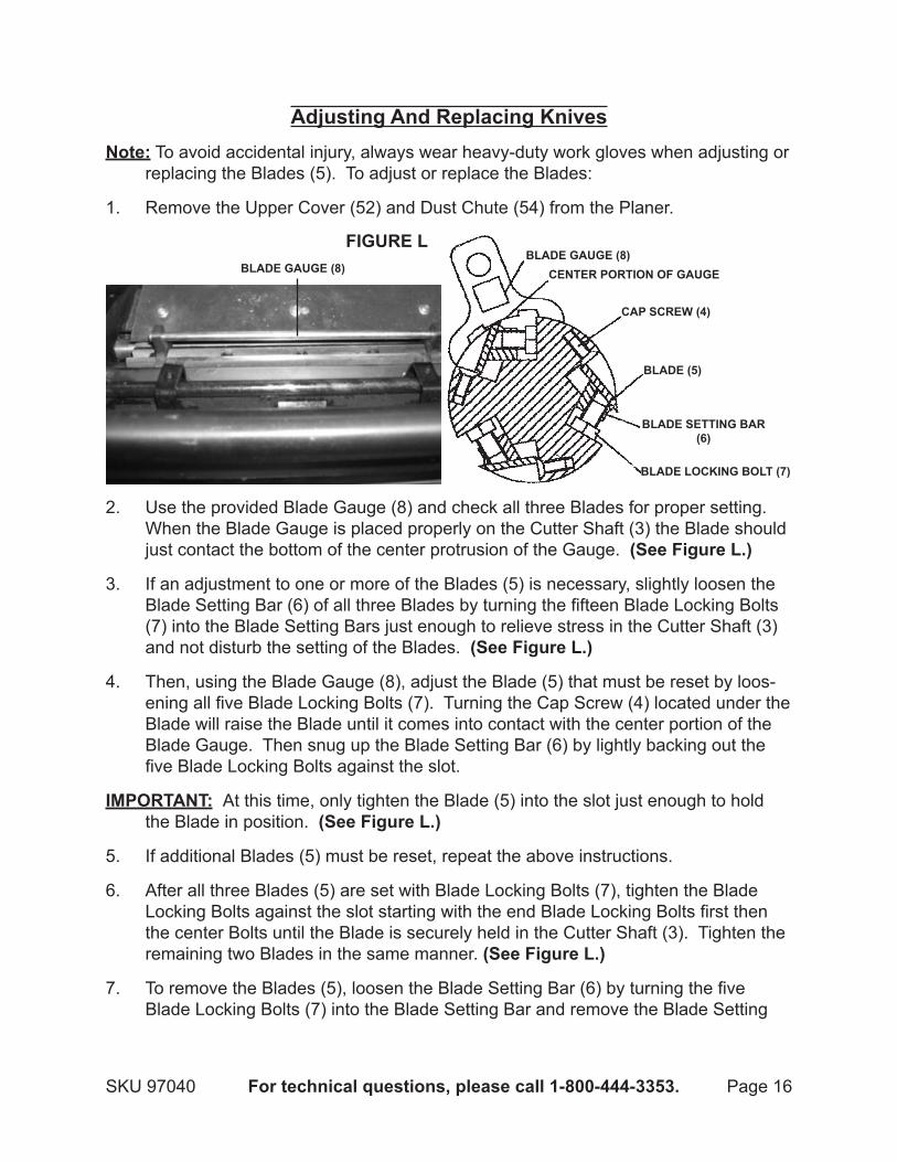
Adjusting And Replacing knivesNote: To avoid accidental injury, always wear heavy-duty work gloves when adjusting or
replacing the Blades (5). To adjust or replace the Blades:
Remove the Upper Cover (52) and Dust Chute (54) from the Planer.1.
bLAdE gAUgE (8)bLAdE gAUgE (8)
CENTER PORTION OF gAUgE
CAP SCREw (4)
bLAdE (5)
bLAdE SETTINg bAR(6)
bLAdE LOCkINg bOLT (7)
FIgURE L
2. Use the provided Blade Gauge (8) and check all three Blades for proper setting. When the Blade Gauge is placed properly on the Cutter Shaft (3) the Blade should just contact the bottom of the center protrusion of the Gauge. (See Figure L.)
If an adjustment to one or more of the Blades (5) is necessary, slightly loosen the 3. Blade Setting Bar (6) of all three Blades by turning the fifteen Blade Locking Bolts (7) into the Blade Setting Bars just enough to relieve stress in the Cutter Shaft (3) and not disturb the setting of the Blades. (See Figure L.)
Then, using the Blade Gauge (8), adjust the Blade (5) that must be reset by loos-4. ening all five Blade Locking Bolts (7). Turning the Cap Screw (4) located under the Blade will raise the Blade until it comes into contact with the center portion of the Blade Gauge. Then snug up the Blade Setting Bar (6) by lightly backing out the five Blade Locking Bolts against the slot.
IMPORTANT: At this time, only tighten the Blade (5) into the slot just enough to hold the Blade in position. (See Figure L.)
If additional Blades (5) must be reset, repeat the above instructions.5.
After all three Blades (5) are set with Blade Locking Bolts (7), tighten the Blade 6. Locking Bolts against the slot starting with the end Blade Locking Bolts first then the center Bolts until the Blade is securely held in the Cutter Shaft (3). Tighten the remaining two Blades in the same manner. (See Figure L.)
To remove the Blades (5), loosen the Blade Setting Bar (6) by turning the five 7. Blade Locking Bolts (7) into the Blade Setting Bar and remove the Blade Setting

Page 17SKU 97040 For technical questions, please call 1-800-444-3353.
Bar, Blade, and Cap Screw (4) located under the Blades. Remove the remaining two Blades in the same manner. (See Figure L.)
Thoroughly clean the Blade slots, Blade Locking Bolts (7), Blade Setting Bar (6), 8. and Cap Screws (4). (See Figure L.)
Inspect the cutting edges of the Blades (5) for nicks or wear. If necessary, have a 9. qualified service technician hone the Blades slightly using a stone. If the Blades are to be sharpened, maintain a cutting angle of 35°. (See Figure L.)
Insert the Cap Screws (4), Blades (5), and Blade Setting Bar (6) into all three slots 10. in the Cutter Shaft (3). Back out the Blade Locking Bolts (7) just enough to hold all three Blades in the Cutter Shaft. (See Figure L.)
Place the Blade Gauge (8) over one of the Blades (5). 11. (See Figure L.)
While holding down on the Blade Gauge (8), loosen all five Blade Locking Bolts 12. (7) until the cutting edge just contacts the bottom of the center protrusion of the Gauge. Then snug up the Blade Setting Bar (6) by slightly backing out the five Blade Locking Bolts against the slot. IMPORTANT: At this time, only tighten the Blade into the slot just enough to hold the Blade in position. Replace and reset the other two Blades (5) in the same manner. (See Figure L.)
After all three Blades (5) are set with the Blade Locking Bolts (7), tighten the five 13. Bolts against the slots starting with the end Bolts first and then the center Bolts until the Blade is securely held in the Cutter Shaft (3). Tighten the remaining two Blades in the same manner. (See Figure L.)
Adjusting The Roller Spring Tension1. The Feed Rollers (18) as well as the Outfeed Roller (30) are under spring tension
and this tension must be sufficient to feed the stock uniformly through the Planer without slipping. Do not make the tension too tight; doing so will prevent uniform stock feeding. (See Figure M.)
To adjust the tension on the Infeed Roller 2. (18), turn the Set Screw (88). Then turn the Set Screw on the opposite end of the Infeed Roller. (See Figure M.)
To adjust the tension on the Outfeed Roller 3. (30), turn the Set Screw (88). Then turn the Set Screw on the opposite end of the Outfeed Roller. (See Figure M.)
FIgURE M

Page 18SKU 97040 For technical questions, please call 1-800-444-3353.
Adjusting Cutterhead Parallel To TableThe height of the Outfeed Roller (30) is adjusted at the factory and set .019” 1. (0.5mm) below the cutting circle. To check and adjust the Outfeed Roller:
2. Make sure the Blades (5) are properly adjusted as explained in the previous sec-tion.
Place a 4” high block of scrap wood 3. on the Middle Table (1A) directly un-derneath the Cutter Shaft (3). (See Figure N.)
Using a .039” (1mm) feeler gauge, 4. placed on top of the wood block, raise or lower the Machine Head (1) until the Blade (5) just touches the feeler gauge when the Blade is at its lowest point. Do not move the Machine Head any further until the height of the Outfeed Roller (30) is adjusted. (See Figure N.)
FIgURE O
5. Move the wood block under one end of the Outfeed Roller (30). The bottom of the Outfeed Roller should just touch the top of the wood block. If an adjustment to the Outfeed Roller is necessary, loosen the Hex Nut (25) and turn the Set Screw (24) until the Outfeed Roller just touches the wood block. Then tighten the Hex Nut. Check and adjust the opposite end of the Outfeed Roller in the same manner. (See Figure O.)
The Cutter Shaft (3) is set parallel to the Middle Table (1A) at the factory, and no 6. further adjustment should be necessary. If the machine is planing a taper, first check to see if the Blades (5) are set properly in the Cutter Shaft (3). Then check to see if the Middle Table (1A) is set parallel to the Cutter Shaft as follows:
FIgURE P

Page 19SKU 97040 For technical questions, please call 1-800-444-3353.
7. Place a 4” high piece of scrap wood on the Middle Table (1A) directly under the front edge of the Machine Head (1). Lower the Machine Head until the front edge of the Machine Head just touches the wood block. (See Figure P.)
Move the wood block to the oppo-8. site end of the Middle Table (1). The distance from the Middle Table to the Machine Head should be the same. (See Figure P.)
Repeat the above Steps on the Out-9. feed end of the Middle Table (1A).
If the Machine Head (1) is not parallel to the Middle Table (1A), with assistance and 10. a proper lifting device, tilt the Planer on its side.
(24)
FIgURE Q
11. Loosen the Bolt (22E). This will allow you to move the Idler Sprocket (9C) assem-bly far enough to release tension on the Chain (8C, 17C). (See Figure Q.)
Remove the Chain (8C, 17C) from the Feed Sprocket (1C, 13C) on the end of the 12. Machine Head (1) that must be adjusted. (See Figure Q.)
Move the 4” high piece of scrap wood under one end of the Outfeed Roller (30). 13. The bottom of the Outfeed Roller should just touch the top of the wood block. If an adjustment to the Outfeed Roller is necessary, loosen the Hex Nut (25) and turn the Set Screw (24) until the Outfeed Roller just touches the wood block. Then tighten the Hex Nut. Check and adjust the opposite end of the Outfeed Roller in the same manner. (See Figure Q.)
FIgURE P
Page 20SKU 97040 For technical questions, please call 1-800-444-3353.
Turn the Feed Sprocket (1C, 13C) by hand to bring that corner into adjustment 14. with the other three corners.
FIgURE R
(1C)
(13C)
IMPORTANT: This adjustment is very sensitive, and it should not be necessary to turn the Feed Sprocket more than one or two teeth. Turning the Feed Sprocket clock-wise will decrease the distance between the Middle Table (1A) and Machine Head (1). Counterclockwise will increase the distance. (See Figure R.)
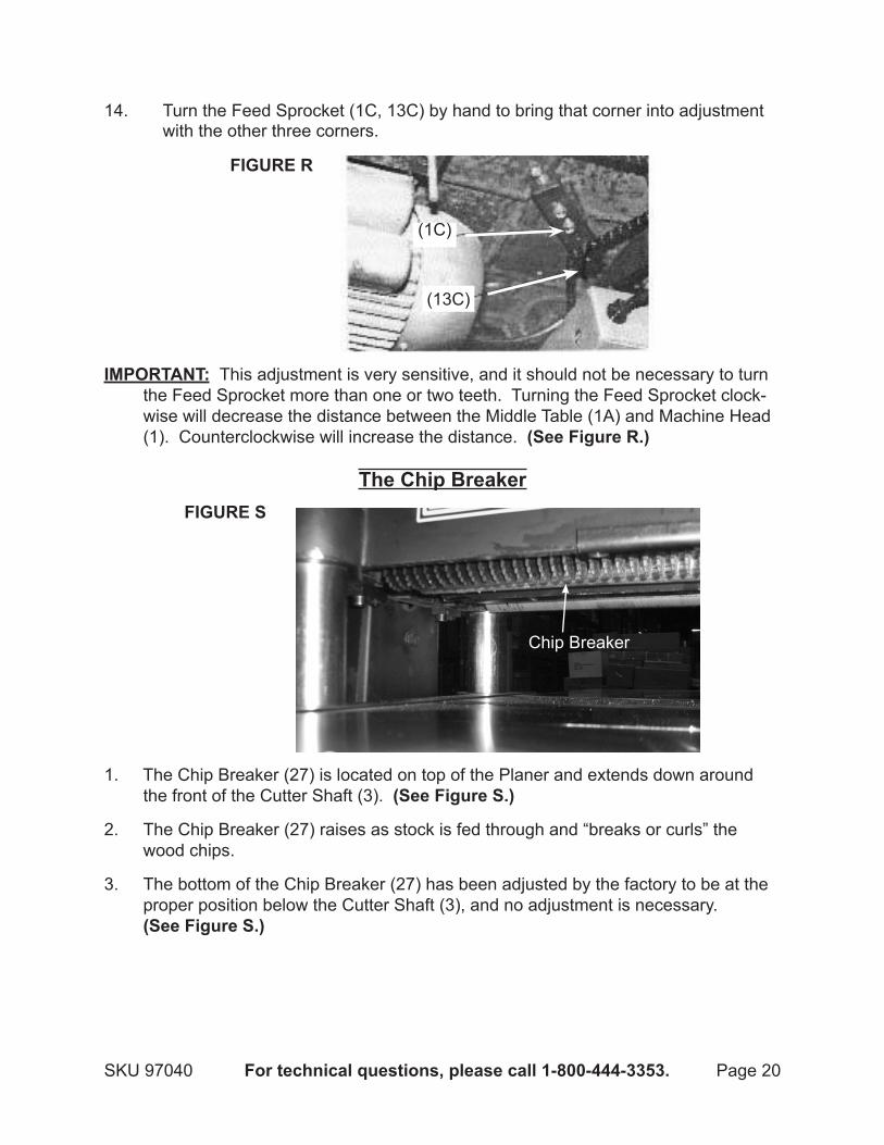
The Chip breaker
Chip Breaker
FIgURE S
1. The Chip Breaker (27) is located on top of the Planer and extends down around the front of the Cutter Shaft (3). (See Figure S.)
The Chip Breaker (27) raises as stock is fed through and “breaks or curls” the 2. wood chips.
The bottom of the Chip Breaker (27) has been adjusted by the factory to be at the 3. proper position below the Cutter Shaft (3), and no adjustment is necessary. (See Figure S.)

Page 21SKU 97040 For technical questions, please call 1-800-444-3353.
Table Roller AdjustmentsFIgURE T
Adjustment to raise and lower rollers.
1. The Planer is equipped with two Table Rollers (7A) which aid in feeding the stock by reducing friction and turning the stock as it is fed through the Planer. (See Figure T.)
It is not possible to give exact dimensions on the proper height setting of the Table 2. Rollers (7A) because each type of wood behaves differently. As a general rule, when planing rough stock the Table Rollers should be set HIGH and when planing smooth stock the Table Rollers should be set LOW. (See Figure T.)
The Table Rollers (7A) on the Planer are factory set for average planing and are 3. parallel to the Middle Table (1A) surface. There are two Adjusting Gauges provid-ed for adjusting the Table Rollers. (See Figure T.)
To adjust the Table Rollers (7A) higher or lower, lay an Adjusting Gauge across 4. the Table Rollers and adjust the height of the Table Rollers by loosening the Set Screws (6A) and turning the Set Screws to raise or lower the Table Rollers. (See Figure T.)
The Adjusting Gauges ensure easy adjustment of the Table Rollers (7A) with three 5. different kinds of height (.005”/.15mm, .011”/.30mm, .017”/.45mm). When planing rough stocks, the Table Rollers should be higher. When planing smooth stocks, the Table Rollers should be lower. (See Figure T.)
The Table Roller (7A) must also be adjusted on the opposite end of the Middle 6. Table (1A) in the same manner. (See Figure T.)

Page 22SKU 97040 For technical questions, please call 1-800-444-3353.
bASIC OPERATINg INSTRUCTIONSMake all necessary set-up procedures and machine adjustments prior to turning on 1. the Planer. Make sure all adjusting keys and wrenches are removed from the ma-chine. And check Blades (5) tightness and alignment before turning on the Planer.
To avoid damage to the Blades (5), check the wood stock for any foreign materials 2. such as nails, screws, or hard impurities in the wood. Also check for loose knots in the wood. Never start the Planer when the Blades are in contact with the work-piece.
Make sure the Power Switch (86) is in its 3. “OFF” position. (See Figure U.)
Connect the Power Cord/Plug (6E) of the Planer to the nearest 240 volt, grounded, 4. electrical outlet.
POwER SwITCH (86)
ON
OFF
FIgURE U
FIgURE V
5. To start the Planer, press the “ON” Button on the Power Switch (86). NOTE: The Planer is equipped with overload protection which will shut off the machine if the unit is overloaded or if line voltage falls below safe levels. If the machine shuts off due to overloading or low voltage, allow the Motor (18E) to cool for approxi-mately five minutes. Raise the Blades slightly to clear the wood. Start the motor and lower the Blades to a lesser height of the previous setting and run the board through. Readjust the head height to a lower setting and run the board through. (See Figure U.)
Once the Planer is running, check for excessive machine vibration. If this is found, 6. turn off the machine and correct the problem before using.

Page 23SKU 97040 For technical questions, please call 1-800-444-3353.
Allow the Blades (5) to turn up to full speed before feeding the wood stock into the 7. Blades. When turning off the Planer, allow the Blades to slow down and stop on their own. Do not press against the Blades to stop them. (See Figure V.)
When feeding the wood stock, use a “push block” (not included) to feed the wood 8. stock rather than using your hands. The push block must be thinner than the wood stock.
When planing a large wood stock, make sure its entire length is properly support-9. ed. If necessary, use a roller stand (not included) with a larger wood stock.
Adjusting for warp: Warp is a variation from a plane or true surface. Warping of 10. wood is caused by uneven shrinkage during the drying process.
The ideal board should not be warped; this allows you to feed its entire width • through the Planer to plane to the desired thickness.With a board having a “cup” warp, you should first plane the top flat and then • turn the board over and plane the bottom flat. If possible, rip the board down the middle of the cup into two pieces. This will eliminate a large amount of waste in the planing process.
IMPORTANT! 11. Feed the board into the Planer, with the grain, so that the Blades (5) travel in the same direction as the slant of the grain.
Grain patterns often have a “V” shape. The point of the “V” should point away • from the Blades (5) while feeding.Occasionally, the grain direction reverses in the same piece of wood. For best • planing results, cut the board in half so that each section can be planed with the grain.
Stand off to one side of the Planer, and feed the wood stock into the Blades (5) 12. gradually. Do not force the machine to remove material faster than it was de-signed to cut.
Never attempt to remove material stuck in the moving parts of the Planer while it is 13. plugged in and running.
Turn off the Planer if the wood stock is to be backed out of an uncompleted cut.14.
After completing a job, always turn the Power Switch (86) to its 15. “OFF” position and unplug the Planer from its electrical outlet. (See Figure U.)

Page 24SKU 97040 For technical questions, please call 1-800-444-3353.
MAINTENANCE ANd SERVICINg Risk of serious personal injury from accidental starting or
electric shock. Turn the Power Switch (86) of the Planer to its “OFF” position and unplug the tool from its electrical outlet before performing any inspection, maintenance, or cleaning procedures.
damaged equipment can fail, causing serious personal injury. do not use damaged equipment. If abnormal noise or vibration occurs, have the problem corrected before further use.
before each use: I1. nspect the general condition of the Planer. Check for loose screws, misalignment or binding of moving parts, cracked or broken parts, dam-aged electrical wiring, and any other condition that may affect its safe operation. do not use damaged equipment.
daily: 2. With a soft brush, cloth, or vacuum, remove all sawdust, wood chips, and debris from the Planer. Then use a lightweight machine oil to lubricate all moving parts.
Every six months: 3. The Gear Box (1D) oil should be changed, using an extreme pressure gear oil. The Chains (8C, 17C) and Sprockets (1C, 9C, 13C) should be lubricated, using a common grease. (See Assy. diagrams.)
wARNINg! 4. If the supply cord of this power tool is damaged, it must be replaced only by a qualified service technician.
CAUTION! 5. All maintenance, service, or repairs not mentioned in this manual must only be performed by a qualified service technician.
Troubleshooting
Problem Possible Causes Possible SolutionsPlaner will not start. No power at outlet.1.
Cord not connected.2. Check power at outlet.1. Check that cord is plugged in.2.
Uneven depth of cut side-to-side.
Blade projection not uniform.1. Cutter Shaft not leveled to Middle Table.2.
Adjust Blade projection.1. Level Cutter Shaft to Middle Table.2.
Chain(s) jumping. Inadequate tension.1. Sprocket(s) misaligned.2.
Adjust Chain tension.1. Align Sprocket(s).2.
Fuzzy grain. Dull Blades. Sharpen Blades.
Torn grain. Too heavy a cut.1. Blades cutting against the grain. 2.
Dull Blades.3.
Review proper depth of cut.1. Feed wood with the grain, or turn 2. workpiece around.Sharpen Blades.3.
Rough/raised grain. Dull Blades.1. Too heavy a cut.2. Moisture content too high.3.
Sharpen Blades.1. Review proper depth of cut.2. Dry the wood.3.
wARNINg

Page 25SKU 97040 For technical questions, please call 1-800-444-3353.
Part description Q’ty1 Machine Head 1
2 Set Screw (M10 x 16) 8
3 Cutter Shaft 1
4 Cap Screw (M5 x 10) 6
5 Blade 3
6 Blade Setting Bar 3
7 Bolt (M8 x 10) 15
8 Blade Gauge 1
9 Blade Gauge Bar 2
10 Retaining Ring (#10) 2
11 Spacer 1
12 Bearing (6205) 1
13 Key (8 x 45) 1
14 Cutter Shaft Pulley 1
15 Pulley Retainer 1
16 Set Screw (M6 x 10) 2
17 Motor Pulley 1
18 Infeed Roller 1
19 Bushing Block 4
20 Spring 4
21 Special Set Screw 4
22 Plate 4
23 Hex Bolt (M8 x 20) 4
24 Set Screw (M6 x 16) 4
25 Hex Nut (M6) 7
26 Key (5 x 15) 2
27 Chip Breaker 1
28 Hex Bolt (M8 x 12) 3
30 Outfeed Roller 1
31 Bearing (61804) 4
32 Upper Shaft 1
33 Middle Shaft 1
34 Short Stud 1
35 Hex Bolt (M5 x 16) 1
36 Hex Bolt (M6 x 12) 20
37 Upper Roller 1
38 Hex Bolt (M6 x 16) 9
40 Flat Washer (#8) 4
43 V-Belt (1100) 3
44 Pulley Cover 1
45 Belt Guard 1
46 Anti-Kickback Finger 46
Part description Q’ty47 Spacer 49
48 Shaft 1
49 Hex Bolt (M6 x 50) 2
50 Depth Limit 1
51 Fit Head Screw (M5 x 10) 2
52 Upper Cover 1
53 Gasket 1
54 Dust Chute 1
55 Roller Stand 3
56 Upper Roller 1
57 Long Stud 1
58 Worm Gear Box 1
59 Cap Screw (M6 x 55) 3
60 Worm 1
61 Bearing (6201) 1
62 Snap Ring (#32) 1
63 Key (4 x 16) 1
64 Hand Wheel 1
65 Collar 1
66 Handle 1
68 Switch Plate 1
69 Name Plate 1
70 Nut (M8) 1
71 Cover 1
72 Flat Washer (#6) 19
73 Lock Washer (#8) 1
74 Spring Block 3
75 Chip Guard Plate 1
76 Screw (M6 x 10) 9
77 Large Flat Washer 2
78 Nut (M5) 2
79 Set Screw (M5 x 16) 2
80 Nut (M4) 2
81 Flat Washer (#4) 4
82 Cap Screw (M4 x 40) 2
83 Power Cord 1
84 Strain Relief 2
85 Bolt 2
86 Power Switch 1
87 Safety Hatch 2
88 Set Screw 4
PARTS LISTS & ASSEMbLY dIAgRAMS
Parts List - Cutter Head

Page 26SKU 97040 For technical questions, please call 1-800-444-3353.
Assembly diagram - Cutter Head
8
88

Page 27SKU 97040 For technical questions, please call 1-800-444-3353.
Parts List & Assembly diagram - Table
Part description Q’ty1A Middle Table 12A Auxiliary Table 23A Flat Washer (#8) 44A Lock Washer (#8) 45A Cap Screw (M8 x 25) 46A Set Screw (M6 x 25) 87A Table Roller 28A Bearing (6201) 49A Eccentric Shaft 4
10A Lock Rod 2
Part description Q’ty11A Knob 212A Threaded Gib 213A Gib 214A Point 115A Rivet (2 x 6) 216A Cap Screw (M6 x 16) 417A Set Screw (M8 x 12) 418A Lock Washer (#6) 819A Screw (M6 x 16) 4
16A
19A
12A
14A
15A17A
10A
13A
11A
9A 8A 7A
18A
6A
1A 2A 3A 4A 5A

Page 28SKU 97040 For technical questions, please call 1-800-444-3353.
Parts List & Assembly diagram - Column
Part description Qty.1B Base 12B Lead Screw Nut 43B Crane Post 44B Scale Column 15B Lead Screw 16B Column 37B Lead Screw 38B Bracket 19B Bolt (M8 x 55) 1
10B Nut (M8) 511B Cap Screw (M8 x 25) 212B Flat Washer (#8) 613B Bearing (6002) 414B Key (4 x 12) 515B Gear 516B Gear Shaft 1
Part description Qty.17B Snap Ring (#32) 418B Bearing (6201) 119B Bushing 120B Gear 121B Snap Ring 222B Set Screw (M8 x 16) 823B Flat Washer (#5) 424B Cap Screw (M5 x 12) 425B Cap Screw (M8 x 30) 426B Flat Washer (#8) 427B Lock Washer 428B Chain 129B Rivet (2 x 6) 230B Scale 131B Washer 4
2b
6b
7b
9b10b
8b
16b
15b
28b
21b 11b
15b31b
12b
17b13b
24b
23b
26b25b
14b
10b27b
12b
3b
1b
22b
5b
30b
4b14b
29b
18b
19b
20b
21b

Page 29SKU 97040 For technical questions, please call 1-800-444-3353.
Parts List & Assembly diagram - gearing
1C
2C
3C
17C
8C
3C
2C
9C
12C
3C
2C
13C
6C
10C
11C 15C
14C
7C
5C 4C
16C
18C
Part description Qty.1C Sprocket 12C Washer 33C Cap Screw (M6 x 16) 34C Flat Washer (#10) 15C Chain Tensioner 16C Shaft 17C Bracket 18C Chain 19C Sprocket 1
Part description Qty.10C Special Bolt 111C Screw (M6 x10) 212C Key (5 x 15) 113C Feed Sprocket 114C Spring 115C Bracket 116C Washer (8 x 22) 217C Chain 118C Clutch Lever 1

Page 30SKU 97040 For technical questions, please call 1-800-444-3353.
Parts List & Assembly diagram - gear box
A8d
11d
9d
8d26d
25d
1d
2d
33d27d
6d7d
3d
4d10d 32d
5d
8db
Ab
Cd
12d13d
14d8d
18d
8d 17d
23d
20d
3dC
24d
22d21d
7d 32d
16d29d
30d
15d
31d d
34d
35d
28d
19d
Part description Qty.1D Gear Box 12D Oil Seal (25 x 40 x 7) 13D Ball Bearing (6204) 24D Gear 15D Cap Screw (M6 x 25-Left) 16D Flat Washer (6 x 22) 17D Lock Bolt (M6 x 12) 28D Bearing (6201) 59D Gear 1
10D Gear & Shaft 111D Key (5 x 12) 112D Gear 113D Key (5 x 10) 114D Gear (2-Speed) 115D Oil Seal (11.8 x 2.65) 116D Washer (#6) 117D Double Gear 118D Gasket 1
Part description Qty.19D Gear Case 120D Key (5 x 40) 121D Steel Ball (#6) 122D Tension Spring 123D Shaft 124D Oil Seal (25 x 47 x 7) 125D Lock Washer (#8) 426D Hex Head Bolt (M8 x 45) 427D Screw (M12 x 1.25 x 16) 228D Hex Head Bolt (M6 x 25) 529D Shifter 130D Shifting Shaft Handle 131D Nut (M8) 132D Lock Washer (#6) 233D Oil Seal (9 x 1.8) 234D Knob 135D Roll Pin (5 x 25) 2

Page 31SKU 97040 For technical questions, please call 1-800-444-3353.
Parts List & Assembly diagram - Stand
6E5E
4E
24E
2E
23E
25E
1E
4E
7E
8E
9E
10E
11E
3E
12E
13E15E
17E
18E15E14E
19E15E10E
22E
21E20E
Part description Qty.1E Stand 12E Wheel 43E Nut (M10) 44E Cover 25E Strain Relief 16E Power Cord 17E Cap Screw (M6 x 16) 88E Flat Washer (#6) 129E Bolt (M8 x 40) 4
10E Flat Washer (#8) 1011E Bolt (M10 x 150) 212E Flat Washer (#10) 4
Part description Qty.13E Motor Mount 114E Lock Washer (#8) 415E Nut (M8) 617E Key (8 x 45) 118E Motor 119E Bar 120E C-Ring (#12) 221E Fixed Bolster 122E Bolt (M8 x 55) 223E Hex Screw (M10 x 80) 424E Lock Nut (M10) 425E Lock Screw 2

Page 32SKU 97040 For technical questions, please call 1-800-444-3353.
LIMITEd 1 YEAR / 90 dAY wARRANTYHarbor Freight Tools Co. makes every effort to assure that its products meet high quality
and durability standards, and warrants to the original purchaser that for a period of ninety days from date of purchase that the engine/motor, the belts (if so equipped), and the blades (if so equipped) are free of defects in materials and workmanship. Harbor Freight Tools also warrants to the original purchaser, for a period of one year from date of purchase, that all other parts and components of the product are free from defects in materials and workmanship (90 days if used by a professional contractor or if used as rental equipment). This warranty does not apply to damage due directly or indirectly, to misuse, abuse, negligence or accidents, repairs or altera-tions outside our facilities, normal wear and tear, or to lack of maintenance. We shall in no event be liable for death, injuries to persons or property, or for incidental, contingent, special or con-sequential damages arising from the use of our product. Some states do not allow the exclusion or limitation of incidental or consequential damages, so the above limitation of exclusion may not apply to you. THIS WARRANTY IS ExPRESSLY IN LIEU OF ALL OTHER WARRANTIES, ExPRESS OR IMPLIED, INCLUDING THE WARRANTIES OF MERCHANTABILITY AND FIT-NESS.
To take advantage of this warranty, the product or part must be returned to us with trans-portation charges prepaid. Proof of purchase date and an explanation of the complaint must accompany the merchandise. If our inspection verifies the defect, we will either repair or replace the product at our election or we may elect to refund the purchase price if we cannot readily and quickly provide you with a replacement. We will return repaired products at our expense, but if we determine there is no defect, or that the defect resulted from causes not within the scope of our warranty, then you must bear the cost of returning the product.
This warranty gives you specific legal rights and you may also have other rights which vary from state to state.
3491 Mission Oaks Blvd. • PO Box 6009 • Camarillo, CA 93011 • (800) 444-3353
Record Product’s Serial Number Here: Note: If product has no serial number, record month and year of purchase instead.
Note: Some parts are listed and shown for illustration purposes only, and are not avail-able individually as replacement parts.
PLEASE REAd THE FOLLOwINg CAREFULLYTHE MANUFACTURER AND/OR DISTRIBUTOR HAS PROVIDED THE PARTS LIST AND ASSEMBLY DIAGRAM IN THIS MANUAL AS A REFERENCE TOOL ONLY. NEITHER THE MANUFACTURER OR DISTRIBUTOR MAKES ANY REPRESENTATION OR WARRANTY OF ANY KIND TO THE BUYER THAT HE OR SHE IS qUALIFIED TO MAKE ANY REPAIRS TO THE PRODUCT, OR THAT HE OR SHE IS qUALIFIED TO REPLACE ANY PARTS OF THE PRODUCT. IN FACT, THE MANUFACTURER AND/OR DISTRIBUTOR ExPRESSLY STATES THAT ALL REPAIRS AND PARTS REPLACEMENTS SHOULD BE UNDERTAKEN BY CERTIFIED AND LICENSED TECHNICIANS, AND NOT BY THE BUYER. THE BUYER ASSUMES ALL RISK AND LIABILITY ARISING OUT OF HIS OR HER REPAIRS TO THE ORIGINAL PRODUCT OR REPLACEMENT PARTS THERETO, OR ARISING OUT OF HIS OR HER INSTALLATION OF REPLACEMENT PARTS THERETO.