automatic rail-weighbridges part 1: metrological and ... · part 1: metrological and technical...
TRANSCRIPT

Automatic rail-weighbridgesPart 1: Metrological and technical requirements - Tests
Ponts-bascules ferroviaires à fonctionnement automatique. Partie 1: Exigences métrologiques et techniques - Essais
OIM
L R 106
-1 Edition 20
11 (E
)
OIML R 106-1Edition 2011 (E)
ORGANISATION INTERNATIONALE
DE MÉTROLOGIE LÉGALE
INTERNATIONAL ORGANIZATION
OF LEGAL METROLOGY
INTERNATIONAL
RECOMMENDATION


OIML R 106-1: 2011 (E)
3
Contents
Foreword ..................................................................................................................................................................................4
0 Terms and definitions .............................................................................................................................................5
1 General .................................................................................................................................................................. 19 1.1 Scope ...................................................................................................................................................................... 19 1.2 Terms and definitions ............................................................................................................................................. 19
2 Metrological requirements ................................................................................................................................... 19 2.1 Accuracy classes ..................................................................................................................................................... 19 2.2 Maximum permissible errors .................................................................................................................................. 19 2.3 Scale interval, d ...................................................................................................................................................... 22 2.4 Scale interval for a stationary load, ds ..................................................................................................................... 22 2.5 Minimum capacity .................................................................................................................................................. 22 2.6 Minimum wagon mass ............................................................................................................................................ 23 2.7 Influence quantities................................................................................................................................................. 23 2.8 Units of measurement ............................................................................................................................................. 24 2.9 Multiple indicating/recording devices .................................................................................................................... 24 2.10 Operating speed ...................................................................................................................................................... 24
3 Technical requirements ........................................................................................................................................ 24 3.1 Suitability for use.................................................................................................................................................... 24 3.2 Security of operation .............................................................................................................................................. 24 3.3 Indication of weighing results................................................................................................................................. 27 3.4 Totalizing device .................................................................................................................................................... 28 3.5 Data storage device ................................................................................................................................................. 28 3.6 Wagon recognition device ...................................................................................................................................... 29 3.7 Installation .............................................................................................................................................................. 29 3.8 Software and hardware requirements ...................................................................................................................... 30 3.9 Securing of components, interfaces and preset controls ......................................................................................... 30 3.10 Span adjustment ...................................................................................................................................................... 31 3.11 Descriptive markings .............................................................................................................................................. 31 3.12 Verification marks .................................................................................................................................................. 33
4 Requirements for electronic instruments ........................................................................................................... 33 4.1 General requirements .............................................................................................................................................. 33 4.2 Application ............................................................................................................................................................. 34 4.3 Functional requirements ......................................................................................................................................... 34
5 Metrological controls ............................................................................................................................................ 35 5.1 Type evaluation ...................................................................................................................................................... 35 5.2 Initial verification ................................................................................................................................................... 38 5.3 Subsequent metrological control ............................................................................................................................ 39
6 Test methods ......................................................................................................................................................... 39 6.1 Test standards ......................................................................................................................................................... 39 6.2 Weighing methods .................................................................................................................................................. 41 6.3 Examination and tests ............................................................................................................................................. 43
Annex A Test procedures for automatic rail-weighbridges .............................................................................................. 44 A.1 Examination for type evaluation ............................................................................................................................. 44 A.2 Examination for initial verification ......................................................................................................................... 44 A.3 General test conditions ........................................................................................................................................... 44 A.4 Test program ........................................................................................................................................................... 46 A.5 Metrological performance tests .............................................................................................................................. 46 A.6 Additional functionality .......................................................................................................................................... 50 A.7 Influence factor and disturbance tests ..................................................................................................................... 51 A.8 Span stability test .................................................................................................................................................... 67 A.9 Procedure for in-situ tests ....................................................................................................................................... 70
Annex B Alignment correction of single-axle rail-weighbridges ...................................................................................... 72
Annex C Guidance for the installation and operation of automatic rail-weighbridges .................................................. 75
Bibliography ............................................................................................................................................................................ 76

OIML R 106-1: 2011 (E)
4
Foreword
The International Organization of Legal Metrology (OIML) is a worldwide, intergovernmental organization whose primary aim is to harmonize the regulations and metrological controls applied by the national metrological services, or related organizations, of its Member States. The main categories of OIML publications are:
International Recommendations (OIML R), which are model regulations that establish the metrological characteristics required of certain measuring instruments and which specify methods and equipment for checking their conformity. OIML Member States shall implement these Recommendations to the greatest possible extent;
International Documents (OIML D), which are informative in nature and which are intended to harmonize and improve work in the field of legal metrology;
International Guides (OIML G), which are also informative in nature and which are intended to give guidelines for the application of certain requirements to legal metrology; and
International Basic Publications (OIML B), which define the operating rules of the various OIML structures and systems.
OIML Draft Recommendations, Documents and Guides are developed by Project Groups linked to Technical Committees or Subcommittees which comprise representatives from OIML Member States. Certain international and regional institutions also participate on a consultation basis. Cooperative agreements have been established between the OIML and certain institutions, such as ISO and the IEC, with the objective of avoiding contradictory requirements. Consequently, manufacturers and users of measuring instruments, test laboratories, etc. may simultaneously apply OIML publications and those of other institutions.
International Recommendations, Documents, Guides and Basic Publications are published in English (E) and translated into French (F) and are subject to periodic revision.
Additionally, the OIML publishes or participates in the publication of Vocabularies (OIML V) and periodically commissions legal metrology experts to write Expert Reports (OIML E). Expert Reports are intended to provide information and advice, and are written solely from the viewpoint of their author, without the involvement of a Technical Committee or Subcommittee, nor that of the CIML. Thus, they do not necessarily represent the views of the OIML.
This publication - reference OIML R 106-1, Edition 2011 (E) - was developed by the OIML Technical Subcommittee TC 9/SC 2 Automatic weighing instruments. It was approved for final publication by the International Committee of Legal Metrology in 2011 and will be submitted to the International Conference of Legal Metrology in 2012 for formal sanction.
OIML Publications may be downloaded from the OIML web site in the form of PDF files. Additional information on OIML Publications may be obtained from the Organization’s headquarters:
Bureau International de Métrologie Légale 11, rue Turgot - 75009 Paris - France Telephone: 33 (0)1 48 78 12 82 Fax: 33 (0)1 42 82 17 27 E-mail: [email protected] Internet: www.oiml.org

OIML R 106-1: 2011 (E)
5
AUTOMATIC RAIL-WEIGHBRIDGES
0 Terms and definitions
The terms and definitions used in this Recommendation conform to the International Vocabulary of Metrology - Basic and General Concepts and Associated Terms (VIM) [1], the International Vocabulary of Legal Metrology (VIML) [2], the OIML Certificate System for Measuring Instruments [3], and to OIML D 11 General requirements for electronic measuring instruments [4]. In addition, for the purposes of this Recommendation, the following definitions apply.
0.1 General definitions
0.1.1 weighing instrument
measuring instrument used to determine the mass of a body by using the action of gravity on the body
Note: In this Recommendation “mass” (or “weight value”) is preferably used in the sense of “conventional mass” or “conventional value of the result of weighing in air” according to OIML R 111 [5] and OIML D 28 [6], whereas “weight” is preferably used for an embodiment (= material measure) of mass that is regulated in regard to its physical and metrological characteristics. According to its method of operation, a weighing instrument is classified as an automatic or non-automatic instrument.
0.1.2 automatic weighing instrument
instrument that weighs without the intervention of an operator and that follows a predetermined program of automatic processes characteristic of the instrument
0.1.3 non-automatic weighing instrument
instrument that requires the intervention of an operator during the weighing process to decide whether the weighing result is acceptable
0.1.4 automatic rail-weighbridge
automatic weighing instrument having one or more load receptor(s), inclusive of rails for conveying railway vehicles, that determines the mass of wagons and/or the whole train by weighing them in motion
0.1.5 railway vehicle
wagon or train to be weighed on an automatic rail-weighbridge
0.1.6 wagon
wagon that is recognized by the automatic rail-weighbridge as a railway vehicle to be weighed

OIML R 106-1: 2011 (E)
6
0.1.7 reference wagon
wagon weighed on the control instrument for temporary use as a mass standard for in-motion testing
0.1.8 uncoupled wagon
single wagon not joined with other wagons
0.1.9 coupled wagon
wagon joined with other wagons
0.1.10 train
number of wagons coupled together with or without a locomotive
0.1.11 control instrument
weighing instrument used to determine the mass of a reference wagon by static weighing
0.1.12 conventional true value (of a quantity)
value attributed to a particular quantity and accepted, sometimes by convention, as having an uncertainty appropriate for a given purpose [VIM 1.20]
0.1.13 metrological authority
legal entity (i.e. the verification and/or issuing authority) designated or formally accepted by the government to be responsible for ascertaining that the automatic weighing instrument satisfies all or some specific requirements of this Recommendation
0.1.14 metrologically relevant
any device, instrument, function or software of an instrument that influences the measurement result or any other primary indication is considered to be metrologically relevant
0.1.15 legally relevant
part of a measuring instrument, device or software subject to legal control
0.2 construction
Note: In this Recommendation the term “device” is used for any means by which a specific function is performed irrespective of the physical realization, e.g. by a mechanism, a key or a special function of the software initiating an operation. The device may be a small part or a major portion of an instrument.

OIML R 106-1: 2011 (E)
7
0.2.1 controlled weighing area
place specified for the operation of an instrument for weighing railway vehicles in motion which is in conformity with the requirements of this Recommendation
0.2.2 weigh zone
zone of the rails on which all axles of a wagon must be located when the wagon is weighed
0.2.3 apron
part of the rails that is not the load receptor but which is located on either end of the load receptor and which serves as approach rails
0.2.4 load receptor
part of the instrument that is intended to receive the load
Note 1: The load receptor may support all the wheels of an axle, a bogie, or a single wagon simultaneously.
Note 2: Two or more load receptors may be placed in series and used as a single load receptor for full-draught weighing or partial weighing (see 0.3.1.2).
0.2.5 electronic instrument
instrument equipped with one or more electronic devices
0.2.5.1 electronic device
device comprising electronic sub-assemblies and performing one or more specific functions, usually manufactured as a separate unit and capable of being independently tested
0.2.5.2 electronic component
smallest physical entity that uses electron or hole conduction in semiconductors, gases, or in a vacuum
0.2.6 module
identifiable part of an instrument that performs a specific function or functions, and that can be separately evaluated according to the metrological and technical performance requirements in the relevant Recommendation
the modules of a weighing instrument are subject to specified partial error limits
Note: Typical modules of an automatic weighing instrument are: load cell, indicator, analogue or digital data processing device, weighing module, terminal, primary display.
OIML R 106-1: 2011 (E)
8
0.2.6.1 load cell
force transducer which, after taking into account the effects of the acceleration of gravity and air buoyancy at the location of its use, measures mass by converting the measured quantity (mass) into another measured quantity (output) [OIML R 60:2000 [6]]
load cells equipped with electronics containing amplifier and analogue-to-digital conversion (ADC) and data processing (optionally) are called digital load cells
0.2.6.2 analogue data processing module
module that performs the analogue-to-digital conversion of the output signal of the load sensor, further processes the data, and supplies the weighing result in a digital format via a digital interface without displaying it
0.2.6.3 digital data processing module
module that further processes the data, and supplies the weighing result in a digital format via a digital interface without displaying it
0.2.6.4 indicator
electronic device of an instrument that may perform the analogue-to-digital conversion of the output signal of the load cell, further processes the data, and displays the weighing result
0.2.6.5 weighing module
part of the weighing instrument that comprises all mechanical and electronic devices (i.e. load receptor, load cell, and the analogue data processing device) but that does not have the means to display the weighing results
it may optionally have devices for further processing (digital) data
0.2.7 interface
0.2.7.1 communication interface
electronic, optical, radio or other hardware and software interface that enables information to be automatically passed between instruments and modules
0.2.7.2 user interface
interface that enables information to be passed between a human user and the instrument or its hardware or software components, e.g. switch, keyboard, mouse, display, monitor, printer, touchscreen

OIML R 106-1: 2011 (E)
9
0.2.7.3 protective interface
interface (hardware and/or software) which only allows the introduction of such data into the data processing device of an instrument, module or electronic component, which cannot:
display data which are not clearly defined and which could be taken for a weighing result; falsify displayed, processed or stored weighing results or primary indications; or adjust the instrument or change any adjustment factor.
0.2.8 software
0.2.8.1 legally relevant software
program, data, type-specific and device-specific parameters that belong to the measuring instrument or device, and define or fulfill functions that are subject to legal control
examples of legally relevant software are: final results of the measurement including the decimal sign and the unit, identification of the weighing range and the load receptor(s)
0.2.8.2
legally relevant parameter parameter of a measuring instrument or a module subject to legal control
the following types of legally relevant parameters can be distinguished: type-specific parameters and device-specific parameters
0.2.8.3 type-specific parameter
legally relevant parameter with a value that depends on the type of instrument only
a legally relevant parameter is fixed at type evaluation of the instrument
examples of type-specific parameters are: parameters used for mass calculation, stability analysis or price calculation and rounding, software identification
0.2.8.4 device-specific parameter
legally relevant parameter with a value that depends on the individual instrument
such parameters comprise calibration parameters (e.g. span adjustments or corrections) and configuration parameters (e.g. maximum capacity, minimum capacity, units of measurement, etc)
they are adjustable or selectable only in a special operational mode of the instrument and may be classified as those that should be secured (unalterable) and those that may be accessed (settable parameters) by an authorized person
0.2.8.5 software identification
sequence of readable characters of software, and that is inextricably linked to the software (e.g. version number, checksum)

OIML R 106-1: 2011 (E)
10
0.2.8.6
software separation
unambiguous separation of software into legally relevant software and non-legally relevant software
if no software separation exists, the whole software is to be considered as legally relevant
0.2.9 data storage device
storage device used for keeping weighing data ready after completion of the measurement for subsequent indication, data transfer, totalizing, etc
0.2.10 zero-setting device
device for setting the indication to zero when there is no load on the load receptor
0.2.10.1 non-automatic zero-setting device
zero-setting device that must be operated manually
0.2.10.2 semi-automatic zero-setting device
zero-setting device that operates automatically following a manual command
0.2.10.3 automatic zero-setting device
zero-setting device that operates automatically and without the intervention of an operator
0.2.10.4 zero-tracking device
device for maintaining the zero indication within certain limits automatically
0.3 metrological characteristics
0.3.1 weighing
0.3.1.1 full-draught weighing
determining the mass of a wagon that is entirely supported on the load receptor(s)
0.3.1.2 partial weighing
determining the mass of a wagon in two or more parts (i.e. axle or bogie partial weighing) successively on the same load receptor

OIML R 106-1: 2011 (E)
11
0.3.1.2.1 axle partial weighing
weighing a wagon for each axle weight on the same load receptor
the results are automatically added to indicate the wagon weight
0.3.1.2.2 bogie partial weighing
weighing a wagon for each bogie weight on the same load receptor
the results are automatically added to indicate the wagon weight
0.3.1.3 weighing-in-motion (WIM)
determining the mass of railway vehicles that are in motion
0.3.1.3.1 uncoupled wagon weighing
determining the mass of wagons that travel independently across the load receptor(s) (this is usually achieved by means of an incline of the approach to the load receptor)
0.3.1.3.2 coupled wagon weighing
determining the individual wagon mass of a train of coupled wagons
0.3.1.3.3 train weighing
determining the totalized mass of a number of wagons coupled together
0.3.1.4 static weighing
determining the mass of a stationary load
0.3.1.5 wagon mass, WM
mass of the single uncoupled wagon combination
0.3.1.5.1 maximum wagon mass
largest wagon mass above which a weighing-in-motion result may be subject to an excessive relative error
0.3.1.5.2 minimum wagon mass
wagon mass below which a weighing-in-motion result may be subject to an excessive relative error
0.3.1.6 train mass
mass of the train combination including all wagon mass and excluding the locomotive

OIML R 106-1: 2011 (E)
12
0.3.1.7 axle
comprises two wheel assemblies with centers of rotation lying approximately on a common axis extending the full width of the wagon and oriented transversely to the nominal direction of travel of the wagon
0.3.1.8 bogie
set of two or more axles included in a defined group at each end of a wagon and their respective interspaces
0.3.1.9 axle load
fraction of the wagon mass that rests via the axle on the load receptor at the time of weighing
0.3.1.10 static reference single-axle load
single-axle load of known conventional true value determined statically for a wagon
0.3.1.11 bogie load
sum of all axle loads in a defined bogie; a fraction of the wagon mass imposed on the static bogie from the effect of gravity at the time of weighing
0.3.1.12 static reference bogie load
bogie load of known conventional true value determined statically on a control instrument for a wagon equipped with four or more axles
0.3.2 capacity
0.3.2.1 maximum capacity, Max
maximum permissible wagon mass.
0.3.2.2 minimum capacity, Min
mass value below which a weighing-in-motion result before totalizing may be subject to an excessive relative error
0.3.2.3 weighing range
range between the minimum and maximum capacities
0.3.3 scale interval, d
value expressed in units of mass for weighing-in-motion of the difference between: the values corresponding to two consecutive scale marks for analogue indication; or two consecutive indicated values for digital indication

OIML R 106-1: 2011 (E)
13
0.3.3.1 scale interval for stationary load, ds
value expressed in units of mass for weighing stationary railway vehicles or test weights of the difference between: the values corresponding to two consecutive scale marks for analogue indication; or two consecutive indicated values for digital indication
0.3.4 speed
0.3.4.1 maximum operating speed, vmax
greatest velocity of a wagon that the instrument is designed to weigh in-motion and above which the weighing result may be subject to an excessive relative error
0.3.4.2 minimum operating speed, vmin
lowest velocity of a wagon that the instrument is designed to weigh in-motion and below which the weighing results may be subject to an excessive relative error
0.3.4.3 range of operating speeds
any speed in the range from the minimum and maximum operating speeds at which a wagon may be weighed-in-motion
0.3.4.4 maximum transit speed
maximum speed, where appropriate, that a railway vehicle can travel on the weigh zone without producing a permanent shift in the performance characteristics of a weighing instrument beyond those specified
0.3.5 warm-up time
time between the moment that power is applied to an instrument and the moment at which the instrument is capable of complying with the requirements
0.3.6 durability
ability of an instrument to maintain its performance characteristics over a period of use
0.3.7 repeatability
ability of an instrument to provide results that agree one with the other under the same operating conditions of measurement [based on VIM 3.6]
0.3.8 final weight value
weight value that is achieved when the instrument is completely at rest and balanced, with no environmental influences or disturbances affecting the indication
Note: This definition is only applicable to static weighing and not to weighing-in-motion.

OIML R 106-1: 2011 (E)
14
0.3.9 stable equilibrium
condition of balance in which an instrument displays a constant value or no more than two adjacent values, one of which is the final weight value, for any given load applied
Note: This definition is only applicable to static weighing and not to weighing-in-motion.
0.3.10 discrimination
ability of an instrument to react to small variations of load
0.3.11 audit trail
electronic count and/or information record of the changes to the values of the legally relevant parameters of a device
0.4 indications and errors 0.4.1 indication quantity value provided by a measuring instrument or a measuring system [VIM 4.1] Note 1: An indication may be presented in visual or acoustic form or may be transferred to another
device. An indication is often given by the position of a pointer on the display for analog outputs, a displayed or printed number for digital outputs, a code pattern for code outputs, or an assigned quantity value for material measures.
Note 2: An indication and a corresponding value of the quantity being measured are not necessarily values of quantities of the same kind.
0.4.1.1 primary indication
indication, signal or symbol that is subject to the requirements of this Recommendation
0.4.1.2 secondary indications
indication, signal or symbol that is not a primary indication
0.4.2 method of indication
0.4.2.1 digital indication
measurement results are displayed by a digital measuring instrument in a digitized form [VIM 4.11]
0.4.2.2 analogue indication
measurement results are displayed by an analogue measuring instrument in a form which is a continuous function of the measurand [VIM 4.10]

OIML R 106-1: 2011 (E)
15
0.4.2.3 printout
hard copy of the measurement results produced from a printer
0.4.3 reading by simple juxtaposition
reading of the weighing result by simple juxtaposition of consecutive figures giving the result, without the need for calculation
0.4.4 error
0.4.4.1 error (of indication)
indication of an instrument minus the (conventional) true value of the corresponding input quantity [VIM 5.20]
0.4.4.2 intrinsic error
error of an instrument determined under reference conditions [VIM 5.24]
0.4.4.3 initial intrinsic error
intrinsic error of an instrument as determined prior to performance tests and durability evaluations
0.4.4.4 maximum permissible error, mpe
extreme value of an error permitted by specifications or regulations between the indication of a weighing instrument and the corresponding true value, as determined by reference standard masses or standard weights, with the instrument being at zero and no load, in the reference position [Adapted from VIM 5.21]
0.4.4.5 fault
difference between the error of indication and the intrinsic error of a weighing instrument
Note: Principally, a fault is the result of an undesired change of data contained in or flowing through an electronic instrument. In this Recommendation, a "fault" is a numerical value.

OIML R 106-1: 2011 (E)
16
0.4.4.6 significant fault
fault greater than 1 d
Note: The relevant Recommendation may specify that the following faults are not significant, even when they exceed the value defined in 0.4.4.6: faults that result from simultaneous and mutually independent causes in the instrument
or in its checking facility; faults that make it impossible to perform any measurement; transitory faults that are momentary variations in the indications which cannot be
interpreted, memorized or transmitted as a measurement result; faults that are so serious that they will inevitably be noticed by those interested in the
measurement.
0.4.4.7 span stability
capability of an instrument to maintain the difference between the indication of mass at maximum capacity and the indication at zero within specified limits over a period of use
0.4.4.8 rounding error of digital indication
difference between the indication and the result the instrument would give with analogue indication
0.4.4.9 repeatability error
difference between the highest and lowest results of successive measurements of the same load carried out under the same (or reasonably constant) conditions of measurement [VIM 3.6]
Note: Repeatability conditions include: the same measurement procedure; the same operator; the same measuring instrument, used under the same conditions; the same location; repetition over a short period of time.
0.5 influences and reference conditions
0.5.1 influence quantity
quantity that is not the measurand but that affects the result of the measurement
0.5.1.1 influence factor
influence quantity having a value within the specified rated operating conditions of the instrument
OIML R 106-1: 2011 (E)
17
0.5.1.2 disturbance
influence quantity having a value that falls within the limits specified in this Recommendation but that falls outside the rated operating conditions of the instrument
0.5.2 rated operating conditions
conditions of use that give the ranges of the influence quantities for which the metrological characteristics are intended to lie within the specified maximum permissible errors
0.5.3 reference conditions
conditions of use prescribed for testing the performance of a measuring instrument or for inter-comparison of results of measurements
Note: The reference conditions generally include reference values or reference ranges for influence quantities affecting the measuring instrument. [VIM 5.7]
0.5.4 normal operating conditions
conditions of use prescribed for operating the instrument including types of wagons, site installation, maintenance and methods of weighing
0.6 tests
0.6.1 static test
test with standard weights (or test loads) remaining stationary on the load receptor to determine an error
0.6.2 in-motion (dynamic) test
test with reference wagons that are in motion on the load receptor to determine an error
0.6.3 simulation test
test carried out on a complete instrument or part of an instrument in which any part of the weighing operation is simulated
0.6.4 performance test
test to verify that the equipment under test (EUT) is capable of accomplishing its intended functions
0.6.5 span stability test
test to verify that the EUT is capable of maintaining its performance characteristics over a period of use

OIML R 106-1: 2011 (E)
18
0.7
abbreviations and symbols
Symbol Meaning
∆L additional load to next changeover point AC alternating current
AWI automatic weighing instrument d actual scale interval
DC direct current ds stationary scale interval E I – L or P – L = error E0 error at zero load
emf electromotive force EUT equipment under test
I indication I/O input / output ports In nth indication
kV kilovolt L load
Max maximum capacity of the weighing instrument MHz megahertz Min minimum capacity of the weighing instrument mpe maximum permissible error
NAWI non-automatic weighing instrument nwmax Maximum number of wagons per train nwmin minimum number of wagons per train
P I + ½ d – ∆L = indication prior to rounding (digital indication) pi fraction of the mpe applicable to a module of the instrument which is examined
separately RF radio frequency sf significant fault
Umax highest value of a voltage range marked on the instrument Umin lowest value of a voltage range marked on the instrument Unom nominal voltage value marked on the instrument V/m volts per metre vmax maximum operating speed vmin minimum operating speed

OIML R 106-1: 2011 (E)
19
1 GENERAL
1.1 Scope
This International Recommendation specifies the requirements and test methods for automatic rail-weighbridges, hereinafter referred to as “instruments”, which are used to determine the mass of railway vehicles (0.1.5) when they are weighed in motion.
It is intended to provide standardized requirements and test procedures to evaluate the metrological and technical characteristics of such instruments in a uniform and traceable way.
1.2 Terms and definitions
The terms and definitions given in clause 0 shall be considered as a binding part of this Recommendation.
2 METROLOGICAL REQUIREMENTS
2.1 Accuracy classes
Instruments are divided into four accuracy classes as follows:
0.2 0.5 1 2
An instrument may be in a different accuracy class for wagon weighing than that for train weighing.
2.2 Maximum permissible errors (mpe)
2.2.1 Weighing-in-motion
The maximum permissible errors for weighing-in-motion shall be as specified in Table 1.
Table 1
Accuracy class Percentage of mass of single wagon or train as appropriate
Initial verification In-service inspection
0.2 ±0.10 % ±0.20 %
0.5 ±0.25 % ±0.50 %
1 ±0.50 % ±1.00 %
2 ±1.00 % ±2.00 %
Note: For the application of maximum permissible errors, refer to 2.2.1.1 and 2.2.1.2.
2.2.1.1 Wagon weighing
The maximum permissible error for uncoupled or coupled wagon weighing shall be one of the following values, whichever is greater:
a) the value calculated according to the appropriate accuracy class in Table 1, rounded to the nearest scale interval;
b) the value calculated according to the appropriate accuracy class in Table 1, rounded to the nearest scale interval for the mass of a single wagon equal to 35 % of the maximum wagon mass (as inscribed on the descriptive markings); or
c) 1 d.

OIML R 106-1: 2011 (E)
20
On initial verification of an instrument weighing coupled wagons, the errors of not more than 10 % of the weighing results taken from one or more passes of the test train may exceed the appropriate maximum permissible error given in Table 1 but shall not exceed two times that value. The wagon in-motion test graph of Figure 1 illustrates this requirement.
2.2.1.2 Train weighing
The maximum permissible error for train weighing shall be one of the following values, whichever is greater:
a) the value calculated according to the appropriate accuracy class in Table 1, rounded to the nearest scale interval;
b) the value calculated according to the appropriate accuracy class in Table 1, for the mass of a single wagon equal to 35 % of the maximum wagon mass (as inscribed on the descriptive markings) multiplied by the number of reference wagons in the train (not exceeding 10 wagons) and rounded to the nearest scale interval, or
c) 1 d for each wagon in the train but not exceeding 10 d.
Wagon weighing
Example according to 2.2.1.1 b) for a class 2 instrument:
Reference wagon mass = 100 t Max wagon mass = 100 t Scale interval = 0.2 t
mpe according to
2.2.1.1a) 1 % × 100 t = 1 t
2.2.1.1 b) 35 % of Max wagon mass = 35 t so error at:
1 % = 0.35 t or 0.4 t rounded, for 90 % (54 out of 60) of reference wagons
2 % = 0.7 t, for 10 % (6 out of 60) reference wagons
2.2.1.1 c) 1 d = 0.2 t
0
0,5
1
1,5
2
2,5
35 100
Erro
r (±)
(tonn
es)
Load (tonnes)
2 % = mpe for not more than 10 % (6 out of 60 reference wagons) weighings
1 % = mpe for 90 % (54 out of 60 reference wagon) weighings
0.2 t = 1 d
Figure 1 - Illustration of maximum permissible errors for coupled wagons

OIML R 106-1: 2011 (E)
21
Train weighing
Example according to 2.2.1.2 b) for a class 1 instrument:
Number of wagons in train = 50
Number of reference wagons in train = 15
Reference wagon mass = 100 t Maximum wagon mass = 100 t Scale interval = 0.2 t
2.2.1.2 a) 0.5 % × 100 t × 15 Reference wagons = 7.5 t mpe according to:
2.2.1.2 b) 35 % × Max wagon mass × 10 Reference wagons = 350 t 0.5 % × 350 t = 1.75 t, rounded to the nearest scale interval = 1.8 t
2.2.1.2 c) 1 d × 10 Reference wagons = 2 t

OIML R 106-1: 2011 (E)
22
2.2.2 Static weighing
The maximum permissible errors on static weighing for increasing or decreasing loads shall be the appropriate values in Table 2.
Table 2
Maximum permissible errors Load, L, expressed in numbers of scale intervals
±0.5 ds 0 ≤ L ≤ 500
±1.0 ds 500 < L ≤ 2 000
±1.5 ds 2 000 < L ≤ 10 000
2.3 Scale interval, d
For a particular method of weighing-in-motion and combination of load receptors, all mass indicating and printing devices on an instrument shall have the same scale interval.
The scale intervals of the indicating devices shall be in the form of 1 × 10k, 2 × 10k, or 5 × 10k, k being a positive or negative whole number or zero.
The relationship between the accuracy class, the scale interval and the maximum wagon mass divided by the scale interval shall be as specified in Table 3.
Table 3
Accuracy class d (kg)
(maximum wagon mass) per scale interval, d
Minimum Maximum
0.2 ≤ 50 1 000 5 000
0.5 ≤ 100 500 2 500
1 ≤ 200 250 1 250
2 ≤ 500 100 600
2.4 Scale interval for a stationary load, ds
If the scale interval for a stationary load, ds, is not equal to the scale interval, d, it shall be automatically out of service when the instrument is in use for weighing-in-motion. In addition, if the instrument is not verified for use as a non-automatic weighing instrument, the scale interval for a stationary load shall not be accessible when the instrument is in use and shall only be used for static testing during metrological controls (see clause 5).
2.5 Minimum capacity
The minimum capacity shall not be less than 1 t, and not greater than the value of the result of the minimum wagon mass divided by the number of partial weighings.

OIML R 106-1: 2011 (E)
23
2.6 Minimum wagon mass
The minimum wagon mass shall not be less than 50 d.
2.7 Influence quantities
2.7.1 Temperature
2.7.1.1 Static temperature
If no particular working temperature is stated in the descriptive markings of an instrument, this instrument shall maintain its metrological properties within the following temperature limits:
–10 °C to +40 °C
Depending on local environmental conditions, however, the limits of the temperature range may differ from the above provided that they are specified in the descriptive markings. The temperature limits may be expressed using the values shown in Table 4, combining any value of the upper row with one value of the lower line provided that any range specified shall be at least 30 °C:
Table 4
Temperature limits: Unit
lower temperature +5 –10 –25 –40 °C
higher temperature +30 +40 +55 +70
2.7.1.2 Temperature effect on no-load indication
The indication at zero or near zero shall not vary by more than one scale interval for a difference in ambient temperature of 5 °C, or it must be assured that the scale is set to zero immediately before the dynamic weighing.
Instruments shall be tested in accordance with the static temperature test in A.7.2.1 and the no-load temperature test in A.7.2.2.
2.7.2 Supply voltage
An electronic instrument shall comply with the appropriate metrological and technical requirements, if the supply voltage varies from the nominal voltage, Unom (if only one voltage is marked on the instrument), or from the voltage range, Umin, Umax, marked on the instrument at: AC mains power supply:
- lower limit = 0.85 Unom or 0.85 Umin - upper limit = 1.10 Unom or 1.10 Umax
External or plug-in power supply device (AC or DC), including rechargeable battery if the battery can be fully (re)charged during the operation of the instrument:
- lower limit = minimum operating voltage - upper limit = 1.20 Unom or 1.20 Umax
Non-rechargeable battery power supply (DC), including rechargeable battery power supply if (re)charge of batteries during the operation of the instrument is not possible:
- lower limit is the minimum operating voltage - upper limit is Unom or Umax

OIML R 106-1: 2011 (E)
24
Note: The minimum operating voltage is defined as the lowest possible operating voltage before the instrument is automatically switched off (see 3.2.3).
Battery-operated and DC mains powered instruments shall either continue to function correctly or not indicate any weight values if the voltage is below the manufacturer’s specified value, the latter being larger than or equal to the minimum operating voltage.
2.8 Units of measurement
The units of mass to be used on an instrument are the kilogram (kg) and the tonne (t).
2.9 Multiple indicating/recording devices
Regardless of the variation in results permitted, the error of any single weighing result shall by itself not exceed the maximum permissible error for the given load.
In addition, for any given load the difference between the indications of multiple indicating devices including tare weighing devices, shall be not greater than the absolute value of the maximum permissible error, but shall be zero between digital displaying and printing devices.
2.10 Operating speed
Operating speed shall be determined by the instrument as the average speed of the railway vehicle as it moves over the load receptor. The weigh-in-motion indication shall include either the speed in km/h at which the entire railway vehicle was weighed in motion, or a notification of speed fault detection.
3 TECHNICAL REQUIREMENTS
3.1 Suitability for use
Instruments shall be designed to suit the railway vehicles, site and method of operation for which they are intended.
3.2 Security of operation
3.2.1 Fraudulent use
An instrument shall have no characteristics likely to facilitate its fraudulent use.
3.2.2 Accidental maladjustment
Instruments shall be constructed so that maladjustments likely to disturb their metrological performance cannot normally take place without their effects being easily detected.
3.2.3 Interlocks
Interlocks (hardware and/or software) shall prevent or indicate the operation of the instrument outside the specified conditions for: minimum operating voltage (2.7.2); wagon recognition (3.6); wheel position on the load receptor (3.6); range of operating speeds (2.10); wagon weighment detection (3.6).

OIML R 106-1: 2011 (E)
25
3.2.4 Uncoupled wagon weighing
Instruments intended for uncoupled wagon weighing shall recognize and indicate the following situations:
a) the passage of a coupled wagon; b) the passage of two or more uncoupled wagons that is sufficiently close to cause either the
instrument malfunction or errors exceeding the appropriate maximum permissible errors; c) whether or not weighing has occurred.
3.2.5 Automatic operation
Instruments shall be designed so that the accuracy and operation of the instrument is within the requirements of this Recommendation for a period specified by the manufacturer durably in accordance with the intended use of the instrument. Any malfunction shall be automatically and clearly indicated (e.g. by a fault indication or by automatic switch off). The documentation submitted by the manufacturer (see A.1.1) shall include a description of how this requirement is met.
The level of confidence shall take account of uncertainties of measurement, significant faults, overload situation, speed fault detection and failure of the instrument.
3.2.6 Use for non-automatic weighing operations
Two cases shall be distinguished: the automatic rail-weighbridge is to be used as an AWl and as a NAWI: it shall comply with
the requirements of this Recommendation and with the requirements of OIML R 76 [7], and it may be used as a control instrument, provided that its error and uncertainty shall be less than one-third (if verified immediately before the in-motion tests) or less than one-fifth (if verified at any other time) of the maximum permissible error for weighing in motion in 2.2.1;
the automatic rail-weighbridge is to be used as an integral control instrument: it shall comply with the requirements of this Recommendation and with the specific tests in 6.2.1 and its error and uncertainty in static weighing shall be less than one-third (if verified immediately before the in-motion tests) or less than one-fifth (if verified at any other time) of the maximum permissible error for weighing in motion in 2.2.1.
3.2.7 Zero-setting and zero-tracking devices (A.5.2)
An instrument may be equipped with a semi-automatic, or automatic zero-setting and/or zero-tracking device for each load receptor.
3.2.7.1 Accuracy of zero-setting
The accuracy of the zero-setting device on the result of the weighing shall be not more than ± 0.25 d.
3.2.7.2 Maximum effect
The effect of the zero-setting device shall not alter the maximum weighing capacity of the instrument.
The range of zero-setting shall not be greater than 4 %, and the range of the initial zero-setting shall not be greater than 20 % of the maximum capacity.
A wider range is possible for the initial zero-setting device if tests show that the instrument complies with the maximum permissible errors in 2.2 and 2.3, the influence factors in 2.7, and the permissible differences in errors in 2.9 for any load compensated by this device within the specified range.

OIML R 106-1: 2011 (E)
26
3.2.7.3 Control of the zero-setting devices
An instrument, whether or not it is equipped with an initial zero-setting device, may have a combined semi-automatic zero-setting and semi-automatic tare-balancing device operated by the same key.
If an instrument has a zero-setting device and a tare-weighing device, the control of the zero-setting device shall be separate from that of the tare-weighing device.
A semi-automatic zero-setting device shall function only: a) when the instrument is in stable equilibrium (3.3.5.3); b) if it cancels any previous tare operation.
A non-automatic or semi-automatic zero-setting device shall not be operable during automatic operation.
3.2.7.4 Stability of an automatic zero-setting device
An automatic zero-setting device may operate at the start of automatic operation, as part of every automatic weighing cycle, or after a programmable time interval. A description of the operation of the automatic zero-setting device (e.g. the maximum programmable time interval) shall be included in the type evaluation certificate.
The operation of the automatic zero-setting device shall be possible only when the instrument is in stable equilibrium (see 3.3.5.3).
Where the automatic zero-setting device operates as part of every automatic weighing cycle, it shall not be possible to disable this device or to set it to operate at time intervals.
Where the automatic zero-setting device operates after a programmable time interval, the manufacturer shall specify the maximum time interval. The actual maximum programmable time interval for automatic zero-setting shall be specified taking into account the actual operating conditions of the instrument. The automatic zero-setting device shall either automatically set to zero after the allocated time or should stop the instrument so that a zero-setting operation can occur or be capable of generating information to draw attention to overdue zero setting.
3.2.7.5 Zero-tracking device
A zero-tracking device shall operate only when: a) the indication is at zero; b) the stability criteria (3.3.5.3) are fulfilled; and c) the corrections are not more than 0.5 d/second.
When zero is indicated after a tare operation, the zero-tracking device may operate within a range of 4 % of Max around the actual zero.
Note: Zero-tracking is functionally similar to automatic zero-setting. The differences are important in applying the requirements of 3.2.7. Refer to 0.2.10. For many types of weighbridge which have automatic zero-setting, zero-tracking will not be appropriate. The maximum rate of correction applicable to zero-tracking does not apply to zero-setting.
Automatic zero-setting is activated by an event, such as part of every automatic weighing cycle or after a programmed interval.
Zero-tracking may operate continuously (when the conditions of 3.3.5.3 are fulfilled) and must therefore be subject to a maximum rate of correction (0.5 d/second) to prevent interaction with the normal weighing process.
OIML R 106-1: 2011 (E)
27
3.3 Indication of weighing results
3.3.1 Quality of indication
Reading of the primary indications (see 0.4.1.1) shall be reliable, easy and unambiguous under normal operating conditions (0.5.4): the overall inaccuracy of reading of an analogue indicating device shall not exceed 0.2 d; the figures, units and designations forming the primary indications shall be of a size, shape
and clarity for reading to be easy; and the scales, numbering and printing shall permit the figures which form the results to be read by
simple juxtaposition (see 0.4.3.1).
3.3.2 Printing device
Printing shall be clear and permanent for the intended use. Printed figures shall be at least 2 mm high.
If printing takes place, the name or the symbol of the unit of measurement shall be either to the right of the value or above a column of values, or placed in accordance with national regulation.
3.3.3 Indications for weighing-in-motion operation
The minimum indications resulting from each weighing-in-motion operation shall be dependent upon the application of the instrument. The indicator shall display at least each wagon mass, and in the case of train weighing it shall display the train mass and the number of wagons in the train. The printout and/or data storage shall indicate at least the date and the time, operating speeds, error messages, instrument identification, each wagon mass and (in the case of train weighing) the train mass and number of wagons in the train.
If a train mass is printed, this must be equal to the mass of the train combination including all wagon mass and excluding the locomotive. If the train includes wagons where no mass was recorded, the total printout must indicate the number of wagons, and also the wagons omitted from the total train mass.
The scale interval of indications for the individual wagon mass or the train mass shall be the scale interval, d, in accordance with 2.3.
Where the scale interval is changed automatically the decimal sign shall maintain its position in the display.
The scale interval of indications of measured or calculated mass values may be to a higher resolution than the scale interval, d.
The results shall bear the name or symbol of the appropriate unit of mass (2.8).
Additional information from the weighing-in-motion operation may include an indication of the maximum allowable weighing speed.
3.3.4 Digital indication
A digital zero indication shall include the display of a zero for all places that are displayed to the right of a decimal sign and at least one place to the left. When no decimal values are displayed, a zero shall be displayed for each place of the displayed division, (i.e. at least one active decade plus any fixed zeros must be displayed).
Below are examples of the number of zeros required:

OIML R 106-1: 2011 (E)
28
Capacity Minimum zero indication (kg)
25 × 0.01 0.00
5 000 × 1 0
100 000 × 20 0
A decimal fraction shall be separated from its integer by a decimal sign (comma or dot, according to national regulations), with the indication showing at least one figure to the left of the sign and all figures to the right.
The decimal sign shall be on one line with the bottom of the figures (example: 0.305 kg).
3.3.5 Limits of indication of weighing results
3.3.5.1 Weighing range
Instruments shall not indicate, record or print the following values unless the value is clearly marked with an error code or message:
the mass of any locomotive; the mass of any wagon that has not been weighed; the mass of any wagon that will cause a weighing result less than Min or greater than
Max + 9 d; the mass of any wagon where the instrument has detected a speed fault condition.
These values may be separated from the other weighing values.
3.3.5.2 Roll back
The indicated values of wagon mass shall not be altered due to any part of any wagon traveling over the load receptor more than once, unless the entire wagon has been reweighed.
3.3.5.3 Stable equilibrium
For each separate weighing test and not for a group of tests, the condition of the instrument shall be such that the indicated mass of each separate weighing test does not deviate by more than 1 ds from the final weight value (0.3.8), i.e. the indicated mass shall show no more than two adjacent values, and (in the case of zero operations) a correct operation of the device according to 3.2.7 and A.6.5 within relevant accuracy requirements is achieved.
3.4 Totalizing device
An instrument may be provided with a totalizing device which totalizes the mass of the individual wagons to provide a totalized mass. Operation of this device may be:
a) automatic, in which case the instrument shall be provided with a railway vehicle recognition device; or
b) semi-automatic (operates automatically following a manual command).
3.5 Data storage device
The measuring instrument shall record by a durable means the measurement result accompanied by information to identify the particular transaction. And a durable proof of the measurement result and the information to identify the transaction shall be available on request at the time the measurement is concluded.

OIML R 106-1: 2011 (E)
29
Metrologically relevant measurement data may be stored in a memory of the instrument or on external storage for subsequent use (e.g. indication, printing, transfer, totalizing, etc.). In this case, the stored data shall be adequately protected against intentional and unintentional changes during the data transmission and/or storage process and shall contain all relevant information necessary to reconstruct an earlier measurement.
There shall be adequate security to ensure that: a) the requirements for security of software given in 3.8 are applied as appropriate; b) if metrologically relevant software realizing short or long term data storage can be transmitted
to or downloaded into the instrument these processes shall be secured in accordance with the requirements of 3.9;
c) external storage device identification and security attributes shall be automatically verified to ensure integrity and authenticity;
d) exchangeable storage media for storing measurement data need not be sealed, provided that the stored data is secured by a specific checksum or key code;
e) when storage capacity is exhausted, new data may replace the oldest data provided that the owner of the old data has given authority to overwrite it.
3.6 Wagon recognition device (3.2.3)
An instrument shall be provided with a wagon recognition device when the wagon mass is indicated automatically following a weighing operation. The device shall detect the presence of a wagon in the weigh zone and shall detect when the whole wagon has been weighed.
If only one direction of travel is specified for an instrument, an error message shall be given or the instrument shall not indicate the wagon mass if it travels in the wrong direction.
3.7 Installation
3.7.1 General
Automatic rail-weighbridges shall be manufactured and installed so as to minimize any adverse effects of the installation environment. The space between the load receptor and the ground shall allow all covered parts of the load receptor to be kept free from all debris or other matter that could affect the accuracy of the instrument. Details of the installation (e.g. site levels, length of aprons) which may affect the weighing operation, and the following effects on the weighing results, should be taken into account: lateral forces due to interactions of the control instrument with the railway vehicle; forces on part of the railway vehicle by different transient behavior and friction within the axle
suspensions; forces on part of the aprons if there are different levels between the control instrument and
ramp that could lead to varying distribution of the axle load.
Further installation information is provided in Annex C.
3.7.2 Composition
Instruments may include the following: one or more load receptors; aprons; railway vehicle-type identification devices (e.g. track switches, load cells, transponder, etc); indicating and printing devices; data processing module.

OIML R 106-1: 2011 (E)
30
3.7.3 Ease of static testing
If it is to be used as the control instrument, the instrument shall be located such that vehicles may easily access it in order to move test weights.
3.7.4 Drainage
If the weighing mechanism is contained in a pit, there shall be a provision (e.g. automatic bilge pump) for drainage to ensure that no portion of the instrument becomes submerged or partially submerged in water or any other liquid.
3.8 Software requirements
There shall be a distinct separation between the legally relevant and non-relevant software (0.2.8.6) in an instrument. The legally relevant software of an instrument shall be identified by the manufacturer, i.e. the software that is critical for measurement characteristics, measurement data and metrologically important parameters, stored or transmitted, and software programmed to detect system faults (software and hardware), is considered as an essential part of an automatic rail-weighbridge and shall meet the requirements for securing software specified in 3.8.2.
3.8.1 Software documentation
The software documentation submitted by the manufacturer may include: a) description of the legally relevant software; b) description of the accuracy of the measuring algorithms; c) description of the user interface, menus and dialogues; d) unambiguous software identification; e) description of the embedded software; f) overview of the system hardware, e.g. topology block diagram, type of computer(s), types of
software functions, etc. if not described in the operating manual; g) means of securing software; h) operating manual.
3.8.2 Means of securing
Adequate security tests shall be conducted to ensure that: a) legally relevant software shall be adequately protected against accidental or intentional
changes. The appropriate requirements for securing given in 3.5 and 3.9 apply; b) the software shall be assigned with appropriate software identification (see 0.2.8.5). This
software identification shall be adapted in the case of every software change that may affect the functions and accuracy of the instrument;
c) functions performed or initiated via connected interfaces, i.e. transmission of legally relevant software, shall comply with the securing requirements for interfaces of 4.3.5.
3.9 Securing of components, interfaces and pre-set controls
3.9.1 General
Components, interfaces, and pre-set controls subject to legal requirements that are not intended to be adjusted or removed by the user shall be fitted with a securing means or shall be enclosed. When enclosed, it shall be possible to seal the enclosure.
Any device for changing the parameters of legally relevant measurement results, particularly for correction and calibration, shall be sealed in a manner that requires the security seal to be broken before an adjustment can be made to any component affecting the performance of an instrument.

OIML R 106-1: 2011 (E)
31
The seals should, in all cases, be easily accessible. Securing should be provided on all parts of the measuring system which cannot be materially protected in any other way against operations liable to affect the measurement accuracy.
3.9.2 Means of securing
Adequate security tests shall be conducted to ensure that: a) access shall only be allowed to authorized persons, e.g. by means of a code (key-word) or of
a special device (hard key, etc); the code must be changeable; b) it shall be possible for the interventions to be memorized and it shall be possible to access and
display this information; the records shall include the date and a means of identifying the authorized person making the intervention (see a) above); the traceability of the interventions shall be assured for at least the period of time in between periodical verifications depending on national regulations. Records may not be overwritten, and if the storage capacities for records are exhausted, no further intervention shall be possible without breaking a physical seal;
c) software functions shall be secured against intentional, unintentional and accidental changes in accordance with the software requirements of 3.8;
d) transmission of legally relevant software and device-specific parameters via interfaces shall be secured against intentional, unintentional and accidental changes in accordance with the requirements of 4.3.5.2;
e) the securing possibilities available in an instrument shall be such that separate securing of the settings is possible;
f) stored data shall be secured against intentional, unintentional and accidental changes in accordance with the data storage requirements of 3.5.
3.10 Span adjustment
An instrument may be fitted with a span adjustment device. This device shall be incorporated inside the instrument. External influence upon this device shall be impossible after securing.
3.11 Descriptive markings
Instruments and associated modules shall bear the following basic markings at each location having a mass indicating device.
3.11.1 Markings shown in full
identification mark and/or name of the manufacturer identification mark and/or name of the importer (if applicable) designation of the instrument serial number of the instrument (including each load receptor, if applicable) weighing method (see 0.3.1) maximum wagon mass ....... kg or t minimum wagon mass ....... kg or t can be used to weigh wagons carrying liquids or other products
that may be subjected to fluctuations in its gravity centre with wagon movement (if applicable)
number of partial weighings (see 0.3.1.2) per wagon (if applicable) maximum operating speed (if applicable) ....... km/h direction of weighing (if applicable) wagons pushed/pulled (whichever is applicable) supply voltage ....... V AC mains frequency (if applicable) ....... Hz temperature range (when not – 10 °C to + 40 °C) ....... °C software identification (compulsory for software controlled instruments)

OIML R 106-1: 2011 (E)
32
3.11.2 Markings shown in code
3.11.2.1 For all instruments
type approval sign in accordance with national requirements accuracy class wagon mass (each weighing method, if applicable) 0.2, 0.5, 1 or 2 accuracy class train mass 0.2, 0.5, 1 or 2 maximum capacity Max = ....... kg or t minimum capacity Min = ....... kg or t scale interval d = ....... kg or t scale interval for stationary load (if applicable) ds = ....... kg or t maximum operating speed vmax = ....... km/h minimum operating speed vmin = ....... km/h
3.11.2.2 For train weighing
Markings required for each weighing method applicable:
maximum number of wagons per train nwmax = ....... minimum number of wagons per train nwmin = .......
3.11.3 Supplementary markings
Depending upon the particular use of the instrument, one or more supplementary markings may be required on type evaluation by the metrological authority issuing the type evaluation certificate.
3.11.4 Presentation of descriptive markings
Descriptive markings shall be indelible and of a size, shape and clarity that permit legibility under normal operation of the instrument.
Descriptive markings may be either in the national language or in the form of adequate, internationally agreed and published pictograms or signs.
They shall be grouped together in a clearly visible place on the instrument, either on a descriptive plate or sticker fixed permanently near the indicating and printing devices, or on a non removable part of the instrument itself. In case of a plate or sticker which is not destroyed when removed, a means of securing shall be provided, e.g. a non removable control mark that can be applied.
It shall be possible to seal the plate bearing the markings, unless it cannot be removed without being destroyed.
The descriptive markings may be shown on a display which is controlled by software provided that: at least Max, Min and d shall be displayed as long as the instrument is switched on; the other markings may be shown on manual command; it must be described in the type approval certificate; the markings are considered as device-specific parameters (see 0.2.8.4, 3.8 and 3.9).
When a display controlled by software is used, the plate of the instrument shall bear at least the following markings: Max, Min and d shall be shown near the display; type approval sign in accordance with national requirements; name or identification mark of the manufacturer; supply voltage; AC mains frequency, (if applicable).

OIML R 106-1: 2011 (E)
33
3.12 Verification marks
3.12.1 Position
Instruments shall have a place for the application of verification marks. The following applies for this place: the part on which the marks are located cannot be removed from the instrument without
damaging the marks; the place shall permit the easy application of the marks without changing the metrological
qualities of the instrument; the marks shall be visible when the instrument is in service.
3.12.2 Mounting
Instruments required to bear verification marks shall have a verification mark support located as specified above, which shall ensure the conservation of the marks. The type and method of sealing shall be determined by national prescription.
4 TECHNICAL REQUIREMENTS FOR ELECTRONIC INSTRUMENTS
Electronic instruments shall comply with the following requirements, in addition to the applicable requirements of all other clauses.
4.1 General requirements
4.1.1 Rated operating conditions
Electronic instruments shall be designed and manufactured so that they do not exceed the maximum permissible errors under rated operating conditions.
4.1.2 Disturbances
Electronic instruments shall be designed and manufactured so that when they are exposed to disturbances, either:
a) significant faults do not occur; or b) significant faults are detected and acted upon.
Note: A fault equal to or less than the value specified in 0.4.4.6 (1 d) is allowed irrespective of the value of the error of indication.
4.1.3 Durability Electronic instruments shall be designed and manufactured so that their ability to meet the requirements of 4.1.1 and 4.1.2 is maintained over a period of use in accordance with the intended use of the instrument.
4.1.4 Evaluation for compliance
A type of an electronic instrument is presumed to comply with the requirements of 4.1.1, 4.1.2, and 4.1.3 if it passes the examination and tests specified in Annex A.

OIML R 106-1: 2011 (E)
34
4.2 Application
The requirements of 4.1.2 may be applied separately to the following: a) each individual cause of significant fault; and/or b) each part of the electronic instrument.
The choice as to whether to apply 4.1.2 (a) or (b) is left to the manufacturer.
4.3 Functional requirements
4.3.1 Acting upon a significant fault
When a significant fault has been detected, a visual or audible indication shall be provided and shall continue until the user takes action or the fault disappears. Means shall be provided to retain any totalized load information contained in the instrument when a significant fault occurs.
4.3.2 Switch-on procedure
If the failure of an indicator display element can cause a false mass indication then the instrument shall have a display test facility which is automatically initiated at switch-on (in the case of electronic instruments permanently connected to the mains at switch-on of indication), e.g. indication of all the relevant signs of the indicator in their active and non-active states for a sufficient time to be easily observed by the operator. This is not applicable for non-segmented displays, on which failures become evident, for example screen-displays, matrix-displays, etc.
4.3.3 Influence factors (A.7.2)
Electronic instruments shall comply with the requirements of 2.7, and in addition they shall maintain their metrological and technical characteristics at a relative humidity of 85 % at the upper limit of the temperature range.
4.3.4 Warm-up time (A.6.1)
During the warm-up time of an electronic instrument, there shall be no indication or transmission of the measurement result and automatic operation shall be inhibited.
4.3.5 Interfaces
An instrument may be equipped with communication interfaces (0.2.7.1) enabling the coupling of the instrument to external equipment, and user interfaces (0.2.7.2) to enable the exchange of information between a human user and the instrument. When an interface is used, the instrument shall continue to function correctly and its metrological functions (including all metrologically relevant parameters and software) shall not be influenced.
4.3.5.1 Interface documentation
The manufacturer shall provide documentation on all interfaces comprising of at least: a) a list of all commands (e.g. menu items); b) description of the software interface; c) a list of all commands together; d) a brief description of their meaning and their effect on the functions and data of the
instrument.
4.3.5.2 Securing of interfaces
Interfaces shall not allow the legally relevant software and functions of the instrument and its measurement data to be inadmissibly influenced by other interconnected instruments, or by disturbances acting on the interface.

OIML R 106-1: 2011 (E)
35
Interfaces through which the functions mentioned above cannot be performed or initiated, need not be secured. Other interfaces shall be secured and tests conducted to ensure that:
a) data is protected (e.g. with a protective interface as defined in 0.2.7.3) against accidental or deliberate interference during the transfer;
b) all functions in the software interface shall be subject to the requirements for securing software in 3.8;
c) all functions in the hardware interface shall be subject to the requirements for securing hardware in 3.9;
d) metrologically relevant parts of the target instrument shall be included in the initial verification (or equivalent conformity assessment procedures);
e) it shall be easily possible to verify the authenticity and integrity of data transmitted to and from the instrument;
f) functions performed or initiated by other connected instruments through the interfaces shall meet the appropriate requirements of this Recommendation.
Other instruments required by national regulation to be connected to the interfaces of an instrument shall be secured to automatically inhibit the operation of the instrument for reasons of the non-presence or improper functioning of the required device.
4.3.6 AC mains power supply
In the event of a power supply failure, the instrument shall retain the metrological information contained in the instrument at the time of failure for at least 24 hours. A switch-over to an emergency power supply shall not cause a significant fault.
4.3.7 DC mains or rechargeable battery supply voltage
An instrument that operates from the DC mains supply, or rechargeable supply shall, whenever the voltage drops below the minimum operating voltage (2.7.2), either continue to function correctly or show an error message or is automatically put out of service.
5 METROLOGICAL CONTROLS
The metrological controls of instruments shall, in conformity with national regulation, consist of the following: type approval; initial verification; subsequent verification; in-service inspection.
Tests should be applied uniformly by the legal metrology services and should form a uniform program. Guidance for the conduct of type approval and initial verification is provided in OIML International Documents D 19 [8] and D 20 [9] respectively.
5.1 Type approval
5.1.1 Documentation
The application for type approval shall include the submission to the metrological authority of the following information and documents, as far as applicable and in accordance with national regulations: metrological characteristics of the instrument (2); a standard set of specifications for the instrument; a functional description of the components and devices (3.7.2, 4.3); drawings, diagrams, photo of the instrument explaining the construction and operation;

OIML R 106-1: 2011 (E)
36
description and application of securing components, interlocks, adjustment devices, controls, fault indication function, etc. (3.2.3, 3.2.5, 3.9, 3.10);
printing devices (3.3.2); data storage device (3.5); zero-setting devices (3.2.7); connection of different load receptors (2.3, 6.2.1.5); interfaces (types, intended use, immunity to external influences instructions (3.9, 4.3.5); for software controlled instruments, general software information (3.8, 3.11.4); description of the stable equilibrium function of the instrument (3.3.5.3); drawing or photo of the instrument showing the principle and the location of control marks,
securing marks, descriptive and verification marks (3.9, 3.11, 3.12); any document or other evidence demonstrating that the design and construction of the
instrument complies with the requirements of this Recommendation; operating instructions, operating manual.
5.1.2 General requirements
Type evaluation shall be carried out on one or more instruments that represent the definitive type submitted in a form suitable for simulation testing in a laboratory. Instruments may be tested on the premises of the metrological authority or in any other mutually agreed and suitable place. Influence factors shall be applied during simulation tests in a manner that will reveal an alteration of the measurement result for any weighing process to which the instrument could be applied. The evaluation shall consist of the tests specified in 5.1.2.1.
5.1.2.1 Type evaluation
The submitted documents shall be examined and tests carried out to verify that the instruments comply with the requirements of this Recommendation.
The metrological characteristics of the instrument in accordance with 3.11 and the specifications for the modular approach of the modules of the instrument in accordance with 5.1.4 shall be examined.
The instruments shall be submitted to the tests in Annex A in accordance with clause 6, using the reference wagons specified in 6.2.3.1, and under the rated operating conditions for the type specification. Errors shall be evaluated as specified in 6.2.3.5.
The metrological authority shall conduct the tests in a manner which prevents an unnecessary commitment of resources and shall permit the results of these tests to be assessed for initial verification when the same instrument is involved. The metrological authority shall check that an instrument specified for static weighing (6.2.1) complies with the requirements of 3.2.6.
The appropriate metrological authority may accept, with the consent of the applicant, test data obtained from other metrological authorities without repeating the tests.
The metrological authority may require the applicant to supply equipment, personnel and a control instrument to perform the tests. The instrument under test may be used as a control instrument provided that it complies with the requirements of 3.2.6 and 6.1.1.2.
5.1.3 Type approval certificate and determination of classes
The type approval certificate shall state the appropriate accuracy classes (0.2, 0.5, 1 or 2) as specified at the type evaluation stage and as determined by compliance with the metrological requirements at initial verification of the instrument.

OIML R 106-1: 2011 (E)
37
5.1.4 Modules
Subject to agreement with the metrological authority, the manufacturer may define and submit modules to be examined separately. This is particularly relevant in the following cases: where testing the instrument as a whole is difficult or impossible; where modules are manufactured and/or placed on the market as separate units to be
incorporated in a complete instrument; where the applicant wants to have a variety of modules included in the approved type; when a module is intended to be used for various kinds of weighing instruments (in particular
load cells, indicators, data storage).
5.1.4.1 Apportioning of errors
Where it is necessary to separately test modules of an instrument or system the following requirements apply.
The error limits applicable to a module which is examined separately are equal to a fraction, pi, of the maximum permissible errors or the allowed variations of the indication of the complete instrument. The fractions for any module have to be taken for the same accuracy class as for the complete instrument incorporating the module.
The fractions pi shall satisfy the following equation:
p12 + p2
2 + p32 + ... ≤ 1
The fraction pi shall be chosen by the manufacturer of the module and shall be verified by an appropriate test, taking into account the following conditions:
for purely digital devices, pi may be equal to 0; for weighing modules, pi may be equal to 1; for all other modules (including digital load cells) the fraction shall not exceed 0.8 and shall
not be less than 0.3, when more than one module contributes to the effect in question.
For mechanical structures evidently designed and manufactured according to sound engineering practice, an overall fraction, pi = 0.5 may be applied without any test, e.g. when levers are made of the same material and when the chain of levers has two planes of symmetry (longitudinal and transversal).
For instruments incorporating the typical modules (see 0.2.6) the fractions pi may have the values given in Table 5, which takes into account the fact that the modules are affected in a different manner depending on the different performance criteria.

OIML R 106-1: 2011 (E)
38
Table 5
Performance criteria Load cell Electronic indicator
Connecting elements, etc.
Combined effect1 0.7 0.5 0.5
Temperature effect on no load indication 0.7 0.5 0.5
Power supply variation - 1 -
Effect of creep 1 - -
Damp heat 0.72 0.5 0.5
Span stability - 1 -
Note 1: Combined effects: non-linearity, hysteresis, temperature effect on span, repeatability, etc. After the warm-up time specified by the manufacturer, the combined effect error fractions apply to modules.
Note 2: According to OIML R 60 [6] valid for SH tested load cells (pLC = 0.7). Note 3: The sign “–” means “not applicable”.
Note 4: See OIML R 76-1(3.9.4) [7] for information on the effects of time.
Note 5: The compatibility check of the weighing instrument and the modules shall be considered in accordance with OIML R 76-1 (Annex F) [7].
5.2 Initial verification
Initial verification shall be carried out in accordance with national regulations by the appropriate metrological authority to establish conformity of the instrument to the approved type and/or the requirements of this Recommendation.
The appropriate metrological authority shall conduct the tests in a manner that prevents an unnecessary commitment of resources. In appropriate situations and to avoid duplicating tests previously performed on the instrument for type evaluation under 5.1.2, the authority may use the results of observed tests for initial verification.
5.2.1 Initial verification tests
Initial verification tests shall be carried out to verify compliance with the requirements of clause 2 (except 2.7) and clause 3 for the type of wagon for which they are intended and under normal operating conditions (0.5.4).
Tests shall be carried out by the appropriate metrological authority with the instrument installed to include all devices which form the assembly as intended for normal operation.
The metrological authority may require the applicant to supply equipment, personnel and a control instrument to perform the tests. The instrument under test may be used as a control instrument provided that it complies with the requirements of 6.2.1.
5.2.2 Conformity
A declaration of conformity to the approved type and/or this Recommendation shall cover: compliance with the appropriate maximum permissible errors in 2.2.1; correct functioning of all devices, e.g. interlocks, indicating and printing devices; construction material and design, as far as they are of metrological relevance;

OIML R 106-1: 2011 (E)
39
confirmation of compatibility of the modules if the modular approach according to 5.1.4 has been chosen; and if appropriate a list of the tests performed.
5.2.3 Visual inspection
Before testing, the instrument shall be visually inspected for: conformity to the approved type; metrological characteristics, i.e. scale interval, minimum capacity, etc.; identification of software (if applicable); identification of modules (if applicable); and prescribed inscriptions and positions for verification and control marks.
5.2.4 Marking and securing
According to national regulations, initial verification may be testified by verification marks as specified in 3.12. National regulations may also require securing of devices whose dismantling or maladjustment might alter the metrological characteristics of the instrument without the alterations being clearly visible. The provisions of 3.9 and 3.12 shall be observed.
5.2.5 Application of accuracy class
Accuracy class requirements shall be applied in accordance with the appropriate parts in 2.2.1 for initial verification.
5.3 Subsequent metrological control
Subsequent metrological control may be performed according to national regulations.
5.3.1 Subsequent verification
Subsequent verification shall be carried out in accordance with the same provisions as in 5.2 for initial verification with the same error limits as those on initial verification. Marking and securing may take place according to 5.2.4, the date being that of the subsequent verification.
5.3.2 In-service inspection
In-service inspection shall be carried out in accordance with the same provisions as in 5.2 for initial verification, with the exception that the in-service maximum permissible errors in 2.2.1 shall be applied. Marking and securing may remain unchanged, or renewed as per 5.3.1.
6 TEST METHODS
6.1 Test standards
6.1.1 Control instruments for reference wagon weighing
The conventional true value of the mass of each reference wagon, when stationary and uncoupled, shall be determined by full-draught weighing on a control instrument. If there is no suitable control instrument for full-draught weighing available with an acceptable accuracy or scale of suitable length, a control instrument for bogie partial weighing (see 0.3.1.2) may be used (A.9.2).
6.1.1.1 Accuracy of control instruments
Where the instrument under test is to be used as an integral control instrument and is verified immediately prior to the weighing tests, its combined error and uncertainty shall be less than one-third of the maximum permissible error in 2.2.1 applicable to the weighing-in-motion instrument under test.

OIML R 106-1: 2011 (E)
40
Where the control instrument is separate from the instrument under test and is verified immediately prior to the weighing tests, its combined error and uncertainty shall be less than one-third of the maximum permissible error for weighing-in-motion in 2.2.1.
Where the control instrument is separate from the instrument under test and is verified at any time other than immediately prior to the weighing tests, its combined error and uncertainty shall be less than one-fifth of the maximum permissible error for weighing-in-motion in 2.2.1.
A control instrument (separate and integral) may be re-verified immediately following completion of the weighing of all reference wagons to ascertain whether or not its performance has changed. For re-verification tests the combined error and uncertainty shall be as specified for the appropriate control instrument.
If the combined error and uncertainty is known by a calibration immediately before (and if appropriate, after) the verification, and under about the same environmental conditions, this error can be taken into account.
6.1.1.2 Integral control instrument
Where the instrument under test is constructed for use as the control instrument it shall have an appropriate scale interval or scale interval for stationary load (2.4) and shall meet the requirements of 6.2.1 (or a similar accuracy must be assured by a defined test procedure which is described in the type evaluation).
6.1.1.3 Partial weighing (see 0.3.1.2) of reference wagons
Where the control instrument is constructed only for partial weighing of reference wagons by individual axle measurement when stationary, it shall have a scale interval for stationary load (2.4), comply with the requirements of 6.2.1, and the alignment correction test for single-axle weighing instruments in Annex B shall be successfully applied.
6.1.2 Test weights
The reference standard weights or masses used for the type examination or verification of an instrument shall principally meet the metrological requirements of OIML R 111 [5]. The combined error and uncertainty of any additional test load used for in-motion tests shall be less than one-third of the applicable instrument maximum permissible errors.
Errors shall be determined with test loads which result in mass values on the instrument: a) at or near minimum wagon mass (0.3.1.5.2); b) at or near maximum wagon mass (0.3.1.5.1); c) at at least two mass values in between a) and b).
6.1.2.1 Distribution of test weights
Except for eccentricity tests, reference standard weights shall be evenly distributed on the load receptor.
For testing control instruments for bogie partial weighing a special test wagon with known mass shall be used. An example is a normal three-axle bogie with a platform for the standard test weights.
6.1.2.2 Substitution of standard test weights at verification (A.5.3.2.4)
When testing instruments at the place of use (application), instead of standard weights any other constant load may be used, provided that standard weights of at least 50 % of Max are used.
If the repeatability error is not greater than 0.3 d, the proportion of standard weights may be reduced to 35 % of Max.
If the repeatability error is not greater than 0.2 d this may be reduced to 20 % of Max.

OIML R 106-1: 2011 (E)
41
The repeatability error has to be determined with a load of adequate stability (weights or any other load) of about the value where the substitution is made, by placing it three times on the load receptor.
6.2 Weighing methods
6.2.1 Static weighing test (A.5.3)
An instrument under test to be used as a control instrument, for the purposes of determining the wagon mass by full-draught or partial weighing, shall meet the requirements of 6.1.1.1 to 6.1.1.3. The maximum permissible errors shall comply with 2.2.2 Table 2.
6.2.1.1 Accuracy of zero-setting (A.5.3.1)
The instrument shall permit the setting of the indication to zero with a deviation of not more than ±0.25 d.
6.2.1.2 Eccentric loading (A.5.3.2.2)
The errors of indications for different positions of the same load shall comply with the maximum permissible errors for the given load.
6.2.1.3 Discrimination test (A.5.3.2.3)
An additional load that is equal to 1.4 ds, when gently placed on or withdrawn from each load receptor in turn when at equilibrium at any load shall change the initial indication.
6.2.1.4 Repeatability test (A.5.3.2.4)
The difference between the results of several weighings of the same load shall not be greater than the absolute value of the maximum permissible error of the instrument for that load.
6.2.1.5 Multiple load receptors
Each load receptor shall be tested by the static-weighing method both independently and in combination.
6.2.2 Devices for selection (or switching) between various load receptors, load-transmitting devices and load-measuring devices
6.2.2.1 Compensation of no-load effect
The selection device shall ensure compensation for the unequal no-load effect of the various load receptors and/or load-transmitting devices in use.
6.2.2.2 Zero-setting
Zero-setting of an instrument with any multiple combination of various load-measuring devices and various load receptors shall be possible without ambiguity and in accordance with the requirements of 3.2.7.
6.2.2.3 Impossibility of weighing
Weighing shall not be possible while selection devices are being used.
6.2.2.4 Identification of the combinations used
Combinations of load receptors and load measuring devices used shall be readily identifiable.
It shall be clearly visible which indication(s) correspond to which load receptor(s).

OIML R 106-1: 2011 (E)
42
6.2.3 In-motion weighing tests
6.2.3.1 Reference wagons
The reference wagons to be used for testing shall represent the range of wagons available in the appropriate Member State and for which the instrument is intended. The reference wagons shall be selected to cover, as far as practicable, each mode of operation for which the instrument is to be approved. Modes of operation include loaded or empty wagons, pushing or pulling, range of operating speeds (Min, Max and Site), and one or both directions.
Where a particular instrument is tested using a limited range of wagon types this shall be recorded in the test report.
Wagons carrying liquid loads or other products that may be subjected to fluctuations in their center of gravity when the wagon moves, shall be used as reference wagons only if the automatic rail-weighbridge will be applied subsequently for determining the mass of such wagons. If the instrument is not intended for this use, it shall bear appropriate marking in accordance with 3.11.
6.2.3.2 Uncoupled (single) wagons
Instruments for weighing individual uncoupled wagons shall be tested using a minimum of five reference wagons having a range of loads from zero load (wagon tare weight) to that of a fully loaded wagon weighed on the instrument at (controlled) operating speeds near min, max and typical site speed, and one or both directions (see A.9.3.1.1). A minimum of five mass indications or printouts of each reference wagon shall be used to assess compliance with the requirements of 2.2.1.1.
6.2.3.3 Coupled wagons or train (A.9.3.2)
The test train shall comprise a number of wagons equal to the maximum number of wagons of a train that the automatic rail-weighbridge is intended to weigh in motion in accordance with Table 6. Test trains should be configured to simulate normal use of the weigh-in-motion system and consist of similar wagons to those being weighed during normal operations.
Where the test train may not contain only reference wagons, the number of reference wagons may be distributed in accordance with Table 6, with a minimum of five, (and normally not more than 15) reference wagons in a test train. The reference wagons shall be coupled consecutively in groups at the front, middle, and rear of the train.
Instruments designed to determine the mass of a total train shall be tested by using a test train of empty reference wagons and a test train of both full and partially loaded reference wagons. Each test train shall be weighed repeatedly on the same instrument in each direction (if applicable) to obtain not less than 60 wagon weights.
Modes of operation include loaded or empty wagons, pushing or pulling, and one or both directions (see A.9.2.3.1).
Table 6
Proportion of reference wagons in a test train
Total number of wagons in test train (nw)
Minimum number of reference wagons
nw ≤ 10 5
10 < nw ≤ 30 10
30 < nw 15

OIML R 106-1: 2011 (E)
43
6.2.3.4 Indicated mass of the reference wagons during in-motion wagon weighing
The mass of the reference wagons shall be displayed and recorded during the weighing operation.
6.2.3.5 Evaluation of errors for in-motion weighing
6.2.3.5.1 Wagon
The error for wagon in-motion weighing shall be equal to the result of subtracting the indicated mass of the reference wagon (6.2.3.4) from the conventional true value of the mass of the reference wagon (6.1.1). The mpe shall be as specified in 2.2.1.1 for initial verification as appropriate for the instrument.
6.2.3.5.2 Train
The error for in-motion train weighing shall be equal to the result of subtracting the sum of the masses of the individual reference wagons (i.e. the conventional true value of the train) from the sum of the indicated masses of the reference wagons. The errors for in-motion train weighing shall not exceed the appropriate mpe in 2.2.1.2 and applied to the summation.
6.3 Examination and tests
6.3.1 Test considerations
All electronic instruments of the same category, whether or not they are equipped with checking facilities, shall be subjected to the same performance test programme as specified in Annex A to determine their correct functioning.
6.3.2 State of the instrument under test
Performance tests shall be carried out on fully operational equipment. When connected in other than a specified operational configuration, the procedure shall be mutually agreed by the approval authority and the applicant, and shall be described in the test document.
If an electronic instrument is equipped with an interface permitting the coupling of the instrument to external equipment, the instrument shall, during the tests in A.7.3.2, A.7.3.3 and A.7.3.4, be coupled to external equipment, as specified by the test procedure.
6.3.3 Span stability tests
The instrument shall be subjected to span stability tests specified in A.8 at various intervals, before, during and after being subjected to performance tests.
OIML R 106-1: 2011 (E)
44
ANNEX A
(Mandatory)
TEST PROCEDURES FOR AUTOMATIC RAIL-WEIGHBRIDGES
A.1 EXAMINATION FOR TYPE EVALUATION
A.1.1 Documentation (5.1.1)
Review the documentation that is submitted, including necessary photographs, drawings, diagrams, general software information, relevant technical and functional description of main components, devices, etc. to determine whether it is adequate and correct, and whether it complies with the instrument submitted. Consider the operating manual.
A.1.2 Comparing construction with documentation (5.1.1)
Examine the various devices of the instrument to ensure compliance with the documentation.
A.1.3 Technical requirements (3)
Examine the instrument for conformity with the technical requirements according to the checklist given in the test report format in OIML R 106-2.
A.1.4 Functional requirements (4.3 and 4.4)
Examine the instrument for conformity with the functional requirements according to the checklist given in the test report format in OIML R 106-2.
A.2 EXAMINATION FOR INITIAL VERIFICATION
A.2.1 Compare construction with documentation (5.2)
Examine the instrument for conformity with the approved type.
A.2.2 Metrological characteristics
Note the metrological characteristics according to the checklist given in the test report format in OIML R 106-2.
A.2.3 Descriptive markings (3.11)
Check the descriptive markings according to the requirements of 3.11 and, if applicable, the requirements of the type evaluation documents.
A.2.4 Verification marks (3.12) and securing means (3.9)
Check the arrangements for verification marks and securing according to the checklist given in the test report format in OIML R 106-2.
A.3 GENERAL TEST REQUIREMENTS
A.3.1 Supply voltage
Connect to the supply voltage and power up the equipment under test (EUT) for a time period equal to or greater than the warm-up time specified by the manufacturer and maintain the EUT energized for the duration of each test.

OIML R 106-1: 2011 (E)
45
A.3.2 Humidity
The handling of the instrument shall be such that no condensation of water occurs on the instrument.
A.3.3 Automatic zero-setting
During the tests, the automatic zero-setting device shall be switched off unless otherwise specified in the relevant test.
A.3.4 Indication with a scale interval smaller than d
If an instrument with digital indication has a device for displaying the indication with a smaller scale interval (not greater than 0.2 d), this device may be used to determine the error. If a device is used it should be noted in the test report.
A.3.5 Calculation of static weighing error
For instruments with digital indication and without a device for displaying the indication with a scale interval of 0.2 d or less, the changeover points are to be used to determine the indication of the instrument, prior to rounding, as follows.
Where necessary, additional weights meeting the requirements of 6.1.2 may be used to assess the rounding error.
A.3.5.1 General method to assess error prior to rounding
For instruments with digital indication having a scale interval, d, changeover points may be used to interpolate between scale intervals, i.e. to determine the indication of the instrument, prior to rounding, as follows:
At a certain load, L, the indicated value, I, is noted. Additional weights of about 0.1 d are successively added until the indication of the instrument is increased unambiguously by one scale interval (I + d). The additional load, ∆L, added to the load receptor gives the indication, P, prior to rounding by using the following formula:
P = I + 0.5 d – ΔL
The error prior to rounding is:
E = P – L = I + 0.5 d – ΔL – L
Example: An instrument with a scale interval, d, of 100 kg is loaded with 10 000 kg and thereby indicates 10 000 kg. After adding successive weights of 100 kg, the indication changes from 10 000 kg to 10 100 kg at an additional load of 30 kg. Inserted in the above formula these observations give:
P = (10 000 + 50 – 30) kg = 10 020 kg
Thus the true indication prior to rounding is 10 020 kg, and the error is:
E = (10 020 – 10 000) kg = 20 kg
A.3.5.2 Correction for error at zero
Evaluate the error at zero load, E0, by the method of A.3.5.1.
Evaluate the error at load L, E, by the method of A.3.5.1.
The corrected error prior to rounding, Ec, is:
Ec = E – E0

OIML R 106-1: 2011 (E)
46
Example: If, for the example in A.3.5.1, the error calculated at zero load was:
E0 = + 10 kg
The corrected error is:
Ec = + 20 – (+ 10) = + 10 kg
A.4 TEST PROGRAM
A.4.1 Type evaluation (5.1)
Clauses A.1, and A.5 to A.9 shall be applied for type evaluation, if applicable.
The tests for clauses A.6 to A.8 shall be performed with a static load, where possible. A wheel movement simulator (switches) may be used if necessary for the calculation of the measurement results.
A.4.2 Initial verification (5.2)
Clauses A.2 and A.9 shall be applied for initial verification.
The test shall include all dynamic in-motion effects corresponding to normal operation of the instrument (0.5.4).
A.5 METROLOGICAL PERFORMANCE TESTS
A.5.1 General conditions
A.5.1.1 Temperature
The tests shall be performed at a steady ambient temperature, usually constant room temperature unless otherwise specified. The temperature is deemed to be steady when the difference between the extreme temperatures noted during the test does not exceed one-fifth of the temperature range of the instrument and the rate of change does not exceed 5 °C per hour.
A.5.1.2 Supply voltage
Instruments shall be connected to the supply voltage and “on” for the duration of the tests.
A.5.1.3 Zero setting
Adjust the EUT as closely as practicable to zero prior to each test, and do not readjust it at any time during the test, except to reset it if a significant fault has occurred.
A.5.1.4 Preloading
Before the first weighing test, the instrument shall be preloaded once to Max.
A.5.1.5 Recovery
After each test, allow the instrument to recover sufficiently before the following test.

OIML R 106-1: 2011 (E)
47
A.5.2 Zero-setting (3.2.7)
A.5.2.1 Range of zero-setting
A.5.2.1.1 Initial zero-setting
The initial zero-setting range is the sum of the positive and negative portions of the initial zero-setting range. If the load receptor cannot readily be removed, only the positive part of the initial zero-setting range needs to be considered.
a) Positive range With the load receptor empty, set the instrument to zero. Place a test load on the load receptor and switch the instrument off and then back on. Continue this process until, after placing a load on the load receptor and switching the instrument off and on, it does not reset to zero. The maximum load that can be re-zeroed is the positive portion of the initial zero-setting range.
b) Negative range Remove any load from the load receptor and set the instrument to zero. Then switch the instrument off and back on. If the instrument can be reset to zero by switching it off and back on, the mass of the load receptor is used as the negative portion of the initial zero-setting range. If the instrument cannot be reset to zero with all the load removed, add weights to any live part of the scale (e.g. on the parts where the load receptor rests) until the instrument indicates zero again. Then remove weights and, after each weight is removed, switch the instrument off and back on. The maximum load that can be removed while the instrument can still be reset to zero by switching it off and on is the negative portion of the initial zero-setting range.
A.5.2.1.2 Semi-automatic zero-setting
This test shall not be carried out during the span stability test.
This test is performed in the same manner as described in A.5.2.1.1, except that the zero-setting device is used rather than switching the instrument on and off.
A.5.2.1.3 Automatic zero-setting
This test shall not be carried out during the span stability test.
If the load receptor cannot readily be removed, a practical approach can be to add weights to the instrument and use another zero-setting device, if provided, to set the instrument to zero. Then remove the weights and check whether the automatic zero-setting still sets the instrument to zero. The maximum weights that can be removed so that the instrument can still be reset to zero is the zero-setting range.
A.5.2.2 Accuracy of zero-setting
The zero-setting device shall either display a special signal when the deviation from zero is more than ±0.25 d, or automatically maintains a “centre of zero” condition to ±0.25 d or less.
A.5.2.2.1 Semi-automatic zero-setting
The accuracy of the zero-setting device is tested by setting the instrument to zero and then determining the additional load at which the indication changes from zero to one scale interval above zero. The error at zero is calculated according to the description in A.3.5.1.

OIML R 106-1: 2011 (E)
48
A.5.2.2.2 Automatic zero-setting or zero-tracking
The indication is brought outside of the automatic range (e.g. by loading with 10 d). Then the additional load at which the indication changes from one scale interval to the next above is determined and the error is calculated according to the description in A.3.5.1. It is assumed that the error at zero load would be equal to the error at the load in question.
A.5.2.3 Setting to zero before loading
For instruments with digital indication, the adjustment to zero or the determination of the zero point is carried out as described in A.5.2.2.
A.5.3 Static weighing for integral control instrument (6.2.1)
This sub-clause is only applicable to the instrument under test if it is to be used as the control instrument.
A.5.3.1 Accuracy of zero-setting (3.2.7)
Determination of the accuracy of zero-setting is carried out as described in A.5.2.2.
A.5.3.2 Determination of weighing performance
The tests are performed on the control instrument in-situ at the time of type evaluation or verification.
A.5.3.2.1 Weighing test (A.9.3.1)
Before the first weighing test the instrument shall be preloaded once to Max.
Apply loads (or substitution material) from zero up to as close to Max as practical, and then remove the loads back to zero. When determining the initial intrinsic error, at least ten different load values are selected, and for other weighing tests at least five are selected. The loads selected shall include values near maximum and near minimum wagon masses, and at least two load values in between the maximum and minimum wagon mass.
It should be noted that when loading or unloading weights the load must be respectively increased or decreased in a uniform progression.
If the instrument is provided with an automatic zero-setting device it may be in operation during the test, in which case the error at zero point shall be determined according to A.5.2.2.2.
The maximum permissible error shall be the appropriate values from clause 2.2.2 for initial verification.
A.5.3.2.2 Eccentricity test (6.2.1.2)
This test shall be carried out without excessive stacking or overlapping of the load on the load receptor provided that conditions are practical and safe.
On an instrument with a load receptor having n points of support with n ≤ 4, the fraction 1/n of Max shall be applied to each section. The test load shall be on the rails covering the test area as is practicable and stacked across each pair of supports of the load receptor, or in the case of a load receptor which consists of several sections, the test load shall be applied to each section.
The location of the load shall be marked on a sketch in the test report.
The error value at each measurement is determined according to A.3.5.1. The zero error, E0, used for the correction is the value determined prior to each measurement. The errors shall not exceed the appropriate maximum permissible errors from 2.2.2 for initial verification.
If the instrument is provided with automatic zero-setting or zero-tracking, it shall not be in operation during the eccentricity tests.
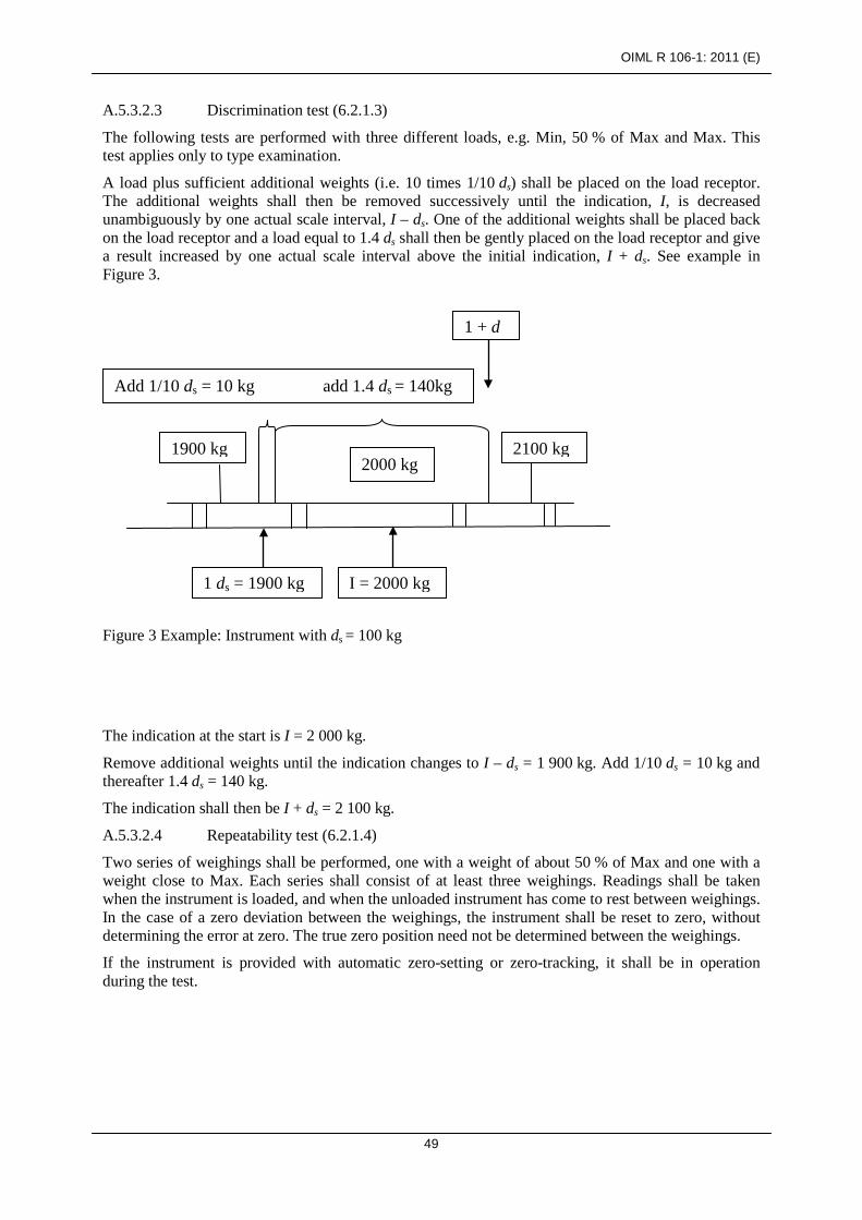
OIML R 106-1: 2011 (E)
49
A.5.3.2.3 Discrimination test (6.2.1.3)
The following tests are performed with three different loads, e.g. Min, 50 % of Max and Max. This test applies only to type examination.
A load plus sufficient additional weights (i.e. 10 times 1/10 ds) shall be placed on the load receptor. The additional weights shall then be removed successively until the indication, I, is decreased unambiguously by one actual scale interval, I – ds. One of the additional weights shall be placed back on the load receptor and a load equal to 1.4 ds shall then be gently placed on the load receptor and give a result increased by one actual scale interval above the initial indication, I + ds. See example in Figure 3.
Figure 3 Example: Instrument with ds = 100 kg
The indication at the start is I = 2 000 kg.
Remove additional weights until the indication changes to I – ds = 1 900 kg. Add 1/10 ds = 10 kg and thereafter 1.4 ds = 140 kg.
The indication shall then be I + ds = 2 100 kg.
A.5.3.2.4 Repeatability test (6.2.1.4)
Two series of weighings shall be performed, one with a weight of about 50 % of Max and one with a weight close to Max. Each series shall consist of at least three weighings. Readings shall be taken when the instrument is loaded, and when the unloaded instrument has come to rest between weighings. In the case of a zero deviation between the weighings, the instrument shall be reset to zero, without determining the error at zero. The true zero position need not be determined between the weighings.
If the instrument is provided with automatic zero-setting or zero-tracking, it shall be in operation during the test.
2100 kg
Add 1/10 ds = 10 kg add 1.4 ds = 140kg
1900 kg
1 + d
2000 kg
1 ds = 1900 kg I = 2000 kg

OIML R 106-1: 2011 (E)
50
A.6 ADDITIONAL FUNCTIONALITY
A.6.1 Warm-up time test (4.3.4)
This test is to verify that metrological performance is maintained in the period immediately after switch on. The method is to check that automatic operation is inhibited until a stable indication is obtained and to verify that zero and span errors comply with the requirements during the first 30 minutes of operation.
a) Disconnect the instrument from the power supply for a period of at least 8 hours prior to the test.
b) Reconnect the instrument and switch on while observing the indicating and printing device. c) Verify that it is not possible to initiate automatic weighing or indication until the indication
has stabilized or until completion of the warm-up time if it is specified by the manufacturer (4.3.4).
d) Verify that the interlock for inhibiting wagon weighment (3.2.3) is operational. e) As soon as the indication of the indicating device has stabilized, set the instrument to zero if
this is not done automatically. f) Apply a load close to Max. Determine the error by the method of A.3.5.1 and A.3.5.2. g) Verify that the zero indication error, E0i, is not greater than 0.25 d (3.2.7) and that the span
error is not greater than the maximum permissible error specified in 2.2.2 for initial verification.
h) Repeat stages e) and f) after 5, 15 and 30 minutes. i) After each time interval verify that the zero variation error (E0 – E0i) is not greater than
0.25 d × pi (see 5.1.4.1).
A.6.2 Agreement between indicating and printing devices (2.9)
During the tests, verify that for the same load, the difference between any two indicating devices having the same scale interval is as follows: zero for digital indicating and printing devices; not greater than the maximum permissible error for analogue devices.
A.6.3 Operating speeds (3.2.3)
Verify that interlocks (hardware and/or software) prevent or indicate the operation of the instrument outside the range of operating speeds.
A.6.4 Functionality at voltages below the minimum operating voltage (4.3.7)
Reduce voltage until the instrument ceases to operate or ceases to give a weight indication. Verify that no malfunction or significant fault occurs before the instrument is thus put out of service. Measure and record the voltage value when the instrument ceases to operate or ceases to give a weight indication and compare this measured value with the manufacturer’s specified value.
A.6.5 Test for stability of equilibrium (3.3.5.3)
Check in the manufacturer’s documentation whether the following stable equilibrium functions are described in sufficient detail: the basic principle, the function and the criteria for stable equilibrium; all adjustable and non-adjustable parameters of the stable equilibrium function (zero-setting,
weighing cycles, etc.); securing of these parameters;

OIML R 106-1: 2011 (E)
51
definition of the most critical adjustment of the stable equilibrium (worst case). This shall cover all variants of a type.
Tests shall be performed with a partially loaded wagon in motion to ensure either that the stability criteria inhibit any weighing operation or that the stable equilibrium criteria of 3.3.5.3 are met. If the instrument can be used to weigh liquid products in a wagon, tests should be performed in conditions where the wagon is stopped just before testing so that either the stability criteria inhibit any weighing operation or that the stable equilibrium criteria of 3.3.5.3 are met.
A.7 INFLUENCE FACTOR AND DISTURBANCE TESTS
A.7.1 Test conditions
A.7.1.1 General requirements
Instruments for wagon and train weighing shall comply with the influence factor and disturbance tests conditions and requirements specified in this Annex.
Influence factor and disturbance tests are intended to verify that instruments can perform and function as intended in the environment and under the conditions specified. Each test indicates, where appropriate, the reference condition under which the intrinsic error is determined.
It is not possible to apply these tests to an instrument that is performing an automatic operation. The instrument shall therefore be subjected to the influence factors and disturbances under static conditions or simulated operation as defined herein. The permissible effects of the influence factors or disturbances under these conditions are specified for each case.
When the effect of one influence factor is being evaluated, all other factors are to be held relatively constant, at a value close to within the reference conditions. After each test, the instrument shall be allowed to recover sufficiently before the following test.
Where modules of the instrument are examined separately, errors shall be apportioned in accordance with 5.1.4.
The operational status of the instrument or simulator shall be recorded for each test.
When an instrument is connected in other than a normal configuration, the procedure shall be mutually agreed on by the approving authority and the applicant.
A.7.1.2 Using a simulator to test modules
A.7.1.2.1 General
If a simulator is used to test a module, the repeatability and stability of the simulator should make it possible to determine the performance of the module with at least the same accuracy as when a complete instrument is tested with a load or weights, the maximum permissible error to be considered being that applicable to the module. The simulator must be capable of providing a minimum input signal, µV/d (normally minimum input voltage) per scale interval.
If a simulator is used, this shall be noted in the test report and its traceability referenced.
The minimum input signal per verification scale interval (µV) for which the indicator is specified shall be less than or equal to the analogue output signal of the load cell(s) connected divided by the number of scale intervals of the weighing instrument.

OIML R 106-1: 2011 (E)
52
A.7.1.2.2 Interfaces (4.3.5)
Susceptibility that would result from the use of interfaces to other equipment shall be simulated in the tests. For this purpose it is sufficient to connect 3 m of interface cable terminated to simulate the interface impedance of the other equipment.
A.7.1.2.3 Documentation
Simulators shall be defined in terms of hardware and functionality by reference to the instrument under test, and by any other documentation necessary to ensure reproducible test conditions. This information shall be attached to, or traceable from, the test report.
A.7.2 Influence factor tests
Summary of tests Test Criteria §
Static temperature mpe* A.7.2.1
Temperature effect on the no-load indication mpe A.7.2.2
Damp heat steady state mpe A.7.2.3
AC mains voltage variations mpe A.7.2.4
DC mains voltage variations mpe A.7.2.5
Battery voltage variations (DC) mpe A.7.2.6
* maximum permissible errors as specified in 2.2.2 Table 1.
A.7.2.1 Static temperature tests (2.7.1.1)
Static temperature tests are carried out according to basic standard IEC Publication 60068-2-1 [10], IEC Publication 60068-2-2 [11] and IEC 60068-3-1 [12], and according to Table 7.
Table 7 - Static temperature test
Environmental phenomena Test specification Test setup
Temperature: Reference temperature of 20 °C
Specified high temperature for 2 hours IEC 60068-2-2
Specified low temperature for 2 hours IEC 60068-2-1
Temperature of 5 °C, if the specified low temperature is ≤ 0 °C IEC 60068-3-1
Reference temperature of 20 °C
Note 1: Use IEC 60068-3-1 for background information. Note 2: The static temperatures test is considered as one test.

OIML R 106-1: 2011 (E)
53
Supplementary information to the IEC test procedures:
Object of the test: To verify compliance with the provisions in 4.1.1 under conditions of dry heat (non-condensing) and cold. The test in A.7.2.2 may be conducted during this test.
Preconditioning: 16 hours
Condition of the EUT: The EUT is connected to the mains power supply and switched on for at least the warm-up time specified by the manufacturer. During the test the electrical power supplied to the EUT shall not be switched off. The zero-setting and zero-tracking facilities shall be enabled as for normal operation. If the test is performed together with A.7.2.2, automatic zero-setting and zero tracking shall not be in operation.
Stabilization: 2 hours at each temperature under “free air” conditions. “Free air” conditions mean a minimum air circulation to keep the temperature at a stable level.
Temperature: As specified in 2.7.1.1.
Temperature sequence: a) at the reference temperature of 20 °C; b) at the specified high temperature; c) at the specified low temperature; d) at a temperature of 5 °C, if the specified low temperature is less than
or equal to 0 °C; and e) at the reference temperature.
Number of test cycles: At least one cycle.
Test information: Adjust the EUT as close to zero indication as practicable prior to the test (if an automatic zero-tracking device is connected, adjust it to a value near zero). The EUT shall not be readjusted at any time during the test.
After stabilization at the reference temperature and again at each specified temperature, apply at least five different test loads (or simulated loads) and record:
a) date and time; b) temperature; c) relative humidity; d) test load; e) indications (as applicable); f) errors; g) functional performance.
Maximum allowable variations:
All functions shall operate as designed.
All errors shall be within the maximum permissible errors specified in 2.2.2 for initial verification.

OIML R 106-1: 2011 (E)
54
A.7.2.2 Temperature effect on the no-load indication (2.7.1.2)
This test does not need to be performed for instruments that have automatic zero-setting as part of every automatic weighing cycle.
The instrument is set to zero, then the temperature is changed from 20 °C to the prescribed highest and lowest temperatures, then to 5 °C (if the specified low temperature is less than or equal to 0 °C), and finally to the reference temperature 20 °C. After temperature stabilization, the error of the zero indication is determined at each temperature level. The change in zero indication per 5 °C is calculated. The changes in these errors are calculated for any two consecutive temperatures of this test.
This test shall be performed together with the temperature test (A.7.2.1). The errors at zero shall then be additionally determined immediately before changing to the next temperature and after the 2-hour period after the instrument has reached stability at this temperature.
Pre-loading is not allowed before these measurements.
Maximum allowable variations: The change in zero indication shall not vary by more than one scale interval for a temperature difference of 5 °C.
Condition of the EUT: Supply voltage “on” for a time period equal to or greater than the warm-up time specified by the manufacturer. Power is to be “on” for the duration of the test.
A.7.2.3 Damp heat, steady-state (4.3.3)
Damp heat, steady state tests are carried out according to basic standard IEC Publication 60068-2-78 [13] and IEC Publication 60068-3-4 [14] and according to Table 8.
Table 8 - Damp heat, steady state test
Environmental phenomena Test specification Test setup
Damp heat, steady state Upper limit temperature and relative humidity of 85 % for 48 hours.
IEC 60068-2-78 IEC 60068-3-4
Note: Use IEC 60068-3-4 for guidance for damp heat tests.
Supplementary information to the IEC test procedures:
Object of the test: To verify compliance with the provisions in 4.1.1 under conditions of high humidity and constant temperature.
Preconditioning: None required.
Condition of the EUT: The EUT is connected to the mains power supply and switched on for at least the warm-up time specified by the manufacturer. During the test the electrical power supplied to the EUT shall not be switched off.
The zero-setting and zero-tracking facilities shall be enabled as for normal operation.
The handling of the EUT shall be such that no condensation of water occurs on the EUT.
Exposure for 48 hours at the upper limit temperature as specified in 2.7.1.1.
Temperature: Reference temperature and at the upper limit as specified in 2.7.1.1.
Temperature-humidity, 1) Initial test: Reference temperature of 20 °C at 50 % humidity;

OIML R 106-1: 2011 (E)
55
48 hour sequence: 2) Middle test: Upper limit temperature at 85 % humidity;
3) Final test: Reference temperature of 20 °C at 50 % humidity.
Number of test cycles: At least one cycle.
Test information: After stabilization of the EUT at reference temperature and 50 % humidity, apply at least five different test loads (or simulated loads) and record:
a) date and time; b) temperature; c) relative humidity; d) test load; e) indications (as applicable); f) errors; g) functional performance.
Increase the temperature in the chamber to the upper limit and increase the relative humidity to 85 %. Maintain the EUT at no load for a period of 48 hours. Following the 48 hours, apply the same test loads (or simulated loads) and record the data as indicated above.
Decrease the relative humidity to 50 % and decrease the temperature in the chamber to the reference temperature. After stabilization of the EUT, apply the same test loads (or simulated loads) and record the data as indicated above.
Allow full recovery of the EUT before any other tests are performed.
Maximum allowable variations:
All functions shall operate as designed.
All errors shall be within the maximum permissible errors specified in 2.2.2 for initial verification.
A.7.2.4 AC mains supply voltage (2.7.2, 4.3.6)
AC mains supply voltage variation tests are carried out according to basic standard IEC/TR Publication 61000-2-1 [15] and IEC Publication 61000-4-1 [16], and according to Table 9.
Table 9 - AC mains voltage
Environmental phenomena Test specification Test setup
AC mains supply voltage variation
Unom
IEC 61000-2-1 IEC 61000-4-1
Upper limit: 110 % of Unom or Umax
Lower limit: 85 % of Unom or Umin
Unom Note: Where an instrument is powered by a three phase supply, the voltage variations shall apply for
each phase successively.

OIML R 106-1: 2011 (E)
56
Supplementary information to the IEC test procedures:
Object of the test: To verify compliance with the provisions in 4.1.1 under conditions of AC mains voltage variations.
Preconditioning: None required.
Condition of the EUT: The EUT is connected to the mains power supply and switched on for at least the warm-up time specified by the manufacturer. During the test the electrical power supplied to the EUT shall not be switched off.
Adjust the EUT as close to zero indication as practicable prior to the test and do not readjust at anytime during the test except to reset if a significant fault has occurred.
Number of test cycles: At least one cycle.
Test information: The EUT shall be tested with a small test load at or near Min and with one test load between 50 % and the maximum capacity of the EUT.
Stabilize the EUT at the nominal voltage, Unom, and record the following data:
a) date and time; b) temperature; c) relative humidity; d) AC voltage; e) test load; f) indications (as applicable); g) errors; h) functional performance.
Repeat the test for each of the voltages defined in IEC 61000-4-1, section 5 (noting the need in certain cases that the weighing test will be repeated at both ends of the voltage range) and record the indications.
Maximum allowable variations:
All functions shall operate as designed.
All errors shall be within the maximum permissible errors specified in 2.2.2 for initial verification.
A.7.2.5 DC mains voltage (2.7.2, 4.3.7)
Instruments operating from DC mains voltage shall fulfill the tests in A.7.2, with the exception of A.7.2.4 which is to be replaced by the test according to basic standard IEC Publication 60654-2 [17] and according to Table 10.

OIML R 106-1: 2011 (E)
57
Table 10 – DC mains voltage variations test
Environmental phenomena Test specification Test setup
DC mains voltage variations:
Unom
IEC 60654-2 Upper limit: 120 % of Unom or Umax
Lower limit: Minimum operating voltage (see 2.7.2)
Unom
Note: If a voltage range is marked, use the average value as the nominal voltage, Unom.
Supplementary information to the IEC test procedures:
Object of the test: To verify compliance with the provisions in 4.1.1 under conditions of DC mains voltage variations.
Pre-condition: None.
Condition of the EUT: The EUT is connected to the mains power supply and switched on for at least the warm-up time specified by the manufacturer. During the test the electrical power supplied to the EUT shall not be switched off.
Adjust the EUT as close to zero indication as practicable, prior to the test and do not readjust at any time during the test except to reset if a significant fault has occurred.
Number of test cycles: At least one cycle.
Test information: Stabilize the EUT at the nominal voltage, Unom, and record the following data at no load and with one small test load:
a) date and time; b) temperature; c) relative humidity; d) supply voltage; e) test load; f) indications (as applicable); g) errors; h) functional performance.
Repeat the test for each of the voltages defined in IEC 60654-2 and record the indications.
Maximum allowable variations:
All functions shall operate as designed.
All errors shall be within the maximum permissible errors specified in 2.2.2 for initial verification.

OIML R 106-1: 2011 (E)
58
A.7.2.6 Battery power supply (DC), not mains connected (2.7.2 and 4.3.7)
Battery-powered instruments shall fulfill the tests in A.7.2, in accordance with Table 11.
Table 11 – Battery voltage variations test
Environmental phenomena Test specification Test setup
Battery voltage variations:
Unom
No reference to standards for this test
Upper limit: Unom or Umax
Lower limit: Minimum operating voltage (see 2.7.2)
Unom
Supplementary test information:
Object of the test: To verify compliance with the provisions in 4.1.1 under conditions of battery voltage variations.
Test procedure in brief:
Preconditioning: None.
Condition of the EUT The EUT is connected to the mains power supply and switched on for at least the warm-up time specified by the manufacturer. During the test the electrical power supplied to the EUT shall not be switched off.
Adjust the EUT as close to zero indication as practicable, prior to the test and do not readjust at any time during the test except to reset if a significant fault has occurred.
Number of test cycles: At least one cycle.
Test information: Stabilize the EUT at the nominal voltage, Unom, and record the following data at no load and with one small test load:
a) date and time; b) temperature; c) relative humidity; d) supply voltage; e) test load; f) indications (as applicable); g) errors; h) functional performance.
Reduce the voltage to the EUT until the instrument ceases to function properly according to the specifications and metrological requirements, and record the indications.
Maximum allowable variations:
All functions shall operate as designed.
All errors shall be within the maximum permissible errors specified in 2.2.2 for initial verification.

OIML R 106-1: 2011 (E)
59
A.7.3 Disturbance tests (4.1.2)
Summary of tests
Test Criteria §
AC mains voltage dips and short interruptions sf* A.7.3.1 Fast transients / burst immunity on mains power supply lines and on the I/O circuits and communication lines sf A.7.3.2
Surges on mains power supply lines and on signal and communication lines sf A.7.3.3
Electrostatic discharges sf A.7.3.4
Immunity to electromagnetic fields sf A.7.3.5
* value of the significant fault (see 0.4.4.6)
Prior to any test, the rounding error shall be set as close as possible to zero.
If there are interfaces to other equipment on the instrument (or simulator), the use of these interfaces shall be simulated in the tests. For this purpose, either an appropriate peripheral device or 3 m of interface cable to simulate the interface impedance of the other equipment, shall be connected to each different type of interface.
A.7.3.1 AC mains voltage dips and short interruptions
AC mains voltage dips and short interruptions tests are carried out according to basic standard IEC Publication 61000-4-11 [18] and according to Table 12.

OIML R 106-1: 2011 (E)
60
Table 12 - Short time power reductions
Environmental phenomena
Test specification Test setup
Test Reduction of amplitude to
Duration / Number of cycles
IEC 61000-4-11 Voltage dips and short interruptions:
Test a 0 % 0.5
Test b 0 % 1
Test c 40 % 10/122
Test d 70 % 25/302
Test e 80 % 250/3002
Short interruption 0 % 250/3002
Note 1: A test generator suitable for reducing the amplitude of one or more half cycles (at zero crossings) of the AC mains voltage for a defined period of time shall be used. The test generator shall be adjusted before connecting the EUT. The mains voltage reductions shall be repeated ten times with an interval of at least ten seconds.
Note 2: These values are for 50 Hz /60 Hz respectively.
Supplementary information to the IEC test procedures:
Object of the test: To verify compliance with the provisions in 4.1.2 under conditions of short time mains voltage interruptions and reductions while observing the weight indication of a single static load.
Preconditioning: None required.
Condition of the EUT: The EUT is connected to the mains power supply and switched on for at least the warm-up time specified by the manufacturer. During the test the electrical power supplied to the EUT shall not be switched off.
Adjust the EUT as close to zero indication as practicable, prior to the test. Zero-setting functions shall not be in operation and are not to be adjusted at any time during the test except to reset if a significant fault has occurred.
Number of test cycles: At least one cycle.
Test information: The EUT shall be tested with one small static test load.
Stabilize all factors at nominal reference conditions. Apply one load or simulated load and record:
a) date and time; b) temperature; c) relative humidity; d) supply voltage; e) test load; f) indications (as applicable); g) errors; h) functional performance.

OIML R 106-1: 2011 (E)
61
In accordance with the test specification in Table 12, interrupt the voltages to the corresponding durations / number of cycles and conduct the test as detailed in IEC 61000-4-11 section 8.2.1. During interruption observe the effect on the EUT and record as appropriate.
Maximum allowable variations:
The difference between the weight indication due to the disturbance and the indication without the disturbance shall either not exceed 1 d or the instrument shall detect and react to a significant fault. In the case of voltage interruptions (0 % for 250/300 cycles), the requirement is for the instrument to recover fully.
A.7.3.2 Bursts/ transients on the mains power supply lines and on signal and communication lines
Electrical fast transients/burst immunity tests are carried out at the positive and the negative polarity for at least 1 min at each polarity in accordance with the basic standard IEC 61000-4-4 [19] and according to Tables 13.1 and 13.2.
Table 13.1 - Bursts (transients) on signals and communication lines
Environmental phenomena Test specification Test setup
Bursts (transients): 1.0 kV (peak) 5/50 ns T1/Th
5 kHz rep. Frequency IEC 61000-4-4
Note: Applicable only to ports or interfacing with cables whose total length may exceed 3 m according to the manufacturer’s functional specification.
Table 13.2 - Bursts (transients) on AC and DC mains power supply lines
Environmental phenomena Test specification Test setup standard
Bursts (transients): 2.0 kV (peak) 5/50 ns T1 /Th
5 kHz rep. frequency IEC 61000-4-4
Note: DC supply lines, not applicable to battery-operated appliance that cannot be connected to the mains while in use.
Supplementary information to the IEC test procedures:
Object of the test: To verify compliance with the provisions in 4.1.2 under conditions where specified bursts of voltage spikes are superimposed separately on the mains voltage, and on the I/O circuits and communication lines (if any), while observing the indications for one static test load.
Preconditioning: None required.
Condition of the EUT: The performance of the test generator shall be verified before connecting the EUT.
The EUT is connected to the mains power supply and switched on for at least the warm-up time specified by the manufacturer. During the test the electrical power supplied to the EUT shall not be switched off.
Adjust the EUT as close to zero indication as practicable, prior to the test. Zero-setting functions shall not be in operation and are not to be

OIML R 106-1: 2011 (E)
62
adjusted at any time during the test except to reset if a significant fault has occurred.
Number of test cycles: At least one cycle.
Test information: Specified bursts of voltage spikes for which the repetition frequency of the impulses and peak values of the output voltage on 50 ohms and 1000 ohms load are defined in the referred standard.
Both positive and negative polarity of the bursts shall be applied. The duration of the test shall not be less than one minute for each amplitude and polarity. The injection network on the mains shall contain blocking filters to prevent the burst energy from being dissipated in the mains. For the coupling of the bursts into the input/output and communication lines, a capacitive coupling clamp as defined in the standard shall be used.
Before any test, stabilize the EUT under constant environmental conditions. Apply one small static test load and record:
a) date and time; b) temperature; c) relative humidity; d) supply voltage; e) test load; f) indications (as applicable); g) errors; h) functional performance.
Maximum allowable variations:
The difference between the weight indication due to the disturbance and the indication without the disturbance shall either not exceed 1 d or the instrument shall detect and react to a significant fault.
A.7.3.3 Surges on mains power supply lines and on signal and communication lines
Electrical surge tests are carried out according to IEC 61000-4-5 [20] and according to Table 14.
Table 14 – Electrical surges
Environmental phenomena Test specification Test setup
Surges on mains voltage lines and on signal, control and
communication lines
Power supply lines: 1.0 kV (peak) line to line 2.0 kV line to earth a) At least three positive and three negative
surges applied synchronously with AC supply voltage in angles 0°, 90°, 180° and 270°.
b) At least three positive and three negative surges applied on DC voltage lines and on signal and communication lines.
IEC 61000-4-5
OIML R 106-1: 2011 (E)
63
Supplementary information to the IEC test procedures:
Object of the test: To verify compliance with the provisions in 4.1.2 under conditions where electrical surges are applied separately to the mains voltage lines, and on signal and communication lines (if any), while observing the indications for one static test load.
Preconditioning: None required.
Condition of the EUT: The characteristics of the test generator shall be verified before connecting the EUT.
The EUT is connected to the mains power supply and switched on for at least the warm-up time specified by the manufacturer. During the test the electrical power supplied to the EUT shall not be switched off.
Adjust the EUT as close to zero indication as practicable, prior to the test. Zero-setting functions shall not be in operation and are not to be adjusted at any time during the test except to reset if a significant fault has occurred.
Number of test cycles: At least one cycle.
Test information: The test consists of exposure to surges for which the rise time, pulse width, peak values of the output voltage/current on high/low impendence load and minimum time interval between two successive pulses are defined in IEC 61000-4-5.
The injection network depends on the lines the surge is coupled to and is defined in IEC 61000-4-5.
The EUT shall be tested with one small static test load.
Before any test, stabilize the EUT under constant environmental conditions. Apply one small static test load and record:
a) date and time; b) temperature; c) relative humidity; d) supply voltage; e) test load; f) indications (as applicable); g) errors; h) functional performance.
Maximum allowable variations:
The difference between the weight indication due to the disturbance and the indication without the disturbance shall either not exceed 1 d or the instrument shall detect and react to a significant fault.
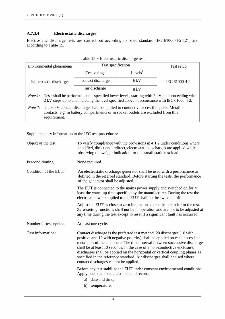
OIML R 106-1: 2011 (E)
64
A.7.3.4 Electrostatic discharges
Electrostatic discharge tests are carried out according to basic standard IEC 61000-4-2 [21] and according to Table 15.
Table 15 - Electrostatic discharge test
Environmental phenomena Test specification Test setup
Electrostatic discharge:
Test voltage Levels1
IEC 61000-4-2 contact discharge 6 kV
air discharge 8 kV Note 1: Tests shall be performed at the specified lower levels, starting with 2 kV and proceeding with
2 kV steps up to and including the level specified above in accordance with IEC 61000-4-2.
Note 2: The 6 kV contact discharge shall be applied to conductive accessible parts. Metallic contacts, e.g. in battery compartments or in socket outlets are excluded from this requirement.
Supplementary information to the IEC test procedures:
Object of the test: To verify compliance with the provisions in 4.1.2 under conditions where specified, direct and indirect, electrostatic discharges are applied while observing the weight indication for one small static test load.
Preconditioning: None required.
Condition of the EUT: An electrostatic discharge generator shall be used with a performance as defined in the referred standard. Before starting the tests, the performance of the generator shall be adjusted.
The EUT is connected to the mains power supply and switched on for at least the warm-up time specified by the manufacturer. During the test the electrical power supplied to the EUT shall not be switched off.
Adjust the EUT as close to zero indication as practicable, prior to the test. Zero-setting functions shall not be in operation and are not to be adjusted at any time during the test except to reset if a significant fault has occurred.
Number of test cycles: At least one cycle.
Test information: Contact discharge is the preferred test method. 20 discharges (10 with positive and 10 with negative polarity) shall be applied on each accessible metal part of the enclosure. The time interval between successive discharges shall be at least 10 seconds. In the case of a non-conductive enclosure, discharges shall be applied on the horizontal or vertical coupling planes as specified in the reference standard. Air discharges shall be used where contact discharges cannot be applied.
Before any test stabilize the EUT under constant environmental conditions. Apply one small static test load and record:
a) date and time; b) temperature;

OIML R 106-1: 2011 (E)
65
c) relative humidity; d) supply voltage; e) test load; f) indications (as applicable); g) errors; h) functional performance.
Maximum allowable variations:
The difference between the weight indication due to the disturbance and the indication without the disturbance shall either not exceed 1 d or the instrument shall detect and react to a significant fault.
A.7.3.5 Immunity to electromagnetic fields
A.7.3.5.1 Radiated electromagnetic immunity tests
Radiated, radio-frequency, electromagnetic field immunity tests (electromagnetic fields higher than 80 MHz) are carried out in accordance to IEC 61000-4-3 [22] and according to Table 16.
Table 16 - Radiated electromagnetic immunity tests
Test specification Environmental
phenomena Frequency ranges
(MHz) Field strength (V/m) Test setup Radiated
electromagnetic immunity tests:
26 to 80(1) 10 IEC 61000-4-3
80 to 2000(2)
Modulation: 80 % AM, 1 kHz sine wave Note 1: For EUTs having no mains or other I/O ports available so that the test according to A.7.3.5.2
cannot be applied, the lower limit of the test is 26 MHz. Note 2: IEC 61000-4-3 only specifies test levels above 80 MHz. For frequencies in the lower range
the test methods for conducted radio frequency disturbances according to A.7.3.5.2 are recommended.
Supplementary information to the IEC test procedures:
Object of the test: To verify compliance with the provisions in 4.1.2 under conditions of specified radiated electromagnetic fields applied while observing the weight indication for one small static test load.
Preconditioning: None required.
Condition of the EUT: The performance of the test generator shall be verified before connecting the EUT.
The EUT is connected to the mains power supply and switched on for at least the warm-up time specified by the manufacturer. During the test the electrical power supplied to the EUT shall not be switched off.
Adjust the EUT as close to zero indication as practicable, prior to the test. Zero-setting functions shall not be in operation and are not to be adjusted at any time during the test except to reset if a significant fault has occurred.
Number of test cycles: At least one cycle.

OIML R 106-1: 2011 (E)
66
Test information: The EUT shall be exposed to electromagnetic field strength as specified in Table 16. The frequency ranges to be considered are swept with the modulated carrier. The performance of the EUT shall be verified.
Before any test stabilize the EUT under constant environmental conditions. Apply one small static test load and record:
a) date and time; b) temperature; c) relative humidity; d) supply voltage; e) test load; f) indications (as applicable); g) errors; h) functional performance.
Maximum allowable variations:
The difference between the weight indication due to the disturbance and the indication without the disturbance shall either not exceed 1 d or the instrument shall detect and react to a significant fault.
A.7.3.5.2 Conducted electromagnetic immunity tests
Conducted, radio-frequency, electromagnetic field immunity tests (electromagnetic fields lower than 80 MHz) are carried out in accordance to IEC 61000-4-6 [23] and according to Table 17.
Table 17 - Conducted electromagnetic immunity tests
Test specification Environmental
phenomena Frequency range RF amplitude (50 ohms) (emf) Test setup
Conducted electromagnetic immunity tests:
0.15 MHz to 80 MHz 10 V IEC 61000-4-6
Modulation: 80 % AM, 1 kHz sine wave
Note: This test is not applicable when the EUT has no mains or other input port.

OIML R 106-1: 2011 (E)
67
Supplementary information to the IEC test procedures:
Object of the test: To verify compliance with the provisions in 4.1.2 under conditions of specified conducted electromagnetic fields applied while observing the weight indication for one small static test load.
Preconditioning: None required.
Condition of the EUT: The performance of the test generator shall be verified before connecting the EUT.
The EUT is connected to the mains power supply and switched on for at least the warm-up time specified by the manufacturer. During the test the electrical power supplied to the EUT shall not be switched off.
Adjust the EUT as close to zero indication as practicable, prior to the test. Zero-setting functions shall not be in operation and are not to be adjusted at any time during the test except to reset if a significant fault has occurred.
Radio frequency EM current, simulating the influence of EM fields, shall be coupled or injected into the mains power ports and I/O ports of the EUT using coupling/decoupling devices as defined in the referred standard.
Number of test cycles: At least one cycle.
Test information: Before any test stabilize the EUT under constant environmental conditions. Apply one small static test load and record:
a) date and time; b) temperature; c) relative humidity; d) supply voltage; e) test load; f) indications (as applicable); g) errors; h) functional performance.
Maximum allowable variations:
The difference between the weight indication due to the disturbance and the indication without the disturbance shall either not exceed 1 d or the instrument shall detect and react to a significant fault.
A.8 SPAN STABILITY TEST (6.3.3)
When the instrument is subjected to the span stability test in Table 18: a) the maximum allowable variation in the errors of indication shall not exceed half the absolute
value of the maximum permissible error in 2.2.2 Table 2 for the test load applied on any of the n measurements;
b) where the differences in the results indicate a trend of more than half the allowable variation specified above, the test shall be continued until the trend comes to rest or reverses itself, or until the error exceeds the maximum allowable variation.
No reference to international standards can be given at the present time.

OIML R 106-1: 2011 (E)
68
Table 18 - Span stability test
Test Characteristic under test Condition applied
Span stability: Stability 1/2 absolute mpe
Note 1: The mpe for the zero point shall also be taken into consideration.
Note 2: mpe on initial verification in 2.2.2 Table 2.
Test method: Span stability.
Object of the test: To verify compliance with the provisions in 6.3.3 after the EUT has been subjected to the performance tests.
Test procedures in brief: The test consists of observing the variations of the error of the EUT or simulator under sufficiently constant ambient conditions (reasonable constant conditions in a laboratory environment) at various intervals: before, during, and after the EUT has been subjected to performance tests.
The performance tests shall include the temperature test and, if applicable, the damp heat test; an endurance test shall not be included. Other performance tests listed in this Annex may be performed.
The EUT shall be disconnected twice from the mains power supply (or battery supply where fitted) for at least 8 hours during the period of the test. The number of disconnections may be increased if so specified by the manufacturer or at the discretion of the approval authority in the absence of any specification.
In the conduct of this test, the operating instructions for the instrument as supplied by the manufacturer shall be considered.
The EUT shall be stabilized at sufficiently constant ambient conditions after switch-on for at least five hours, and at least 16 hours after the temperature and damp heat tests have been performed.
Test severities: Test duration: 28 days or the time period necessary to conduct the performance tests, whichever is less.
Time, t, between tests (days): 0.5 < t < 10.
Test load: Near maximum capacity, Max, the same test weights (or simulated test load) shall be used throughout the test.
Maximum allowable variations:
The variation in the errors of indication shall not exceed half the absolute value of the maximum permissible error in 2.2.2 Table 2 for the test load applied on any of the n measurements.
Number of tests, n: At least 8.
Precondition: None required.
Test equipment: Verified mass standards or simulated load.
Condition of the EUT: Voltage supplied and “on” for a time period equal to or greater than the warm-up time specified by the manufacturer.

OIML R 106-1: 2011 (E)
69
Test sequence: Stabilize all factors at nominal reference conditions.
Adjust the EUT as close to zero as possible.
Automatic zero-tracking shall be made inoperative and automatic built-in span adjustment device shall be made operative.
Initial measurement
Determine the span error using the following method:
1) Determine the initial zero error, E0.
If necessary disable any automatic zero-setting or zero-tracking devices by placing a “zero weight” of for example 10 times the scale interval on the load receptor. Note the indication at zero, I0.
Either by use of an indicator with a suitable higher resolution scale interval or using the change point weight method in A.3.5.1 (noting the total addition change point weight, ∆L0), determine and record the initial zero error, E0.
2) Determine the error at near Max capacity, EL
Carefully remove the change point weights (if used) and apply the test load (or simulated load) and note the indication, IL. Either by use of an indicator with a suitable higher resolution scale interval or using the change point weight method in A.3.5.1 (noting the total addition change point weight, ∆L), determine and record the error at near Max capacity, EL.
Record: a) date and time; b) temperature; c) relative humidity; d) value of 0.1 d; e) test load; f) total of added change point weights at zero load, ∆L0; g) total of added change point weights at test load, ∆L; h) the following indications:
indication at zero, I0, indication of test load, IL;
i) calculate: initial zero error, E0, error at test load, EL;
j) change in location and apply all necessary corrections resulting from variations of temperature, pressure, etc. between the various measurements.
Immediately repeat steps 1) and 2) four more times and determine and record the average value of the error for the five tests.
Subsequent measurements
After observing the time between measurements requirement repeat the test sequence 1) to 2) once recording the data above unless:
a) either the result is outside the maximum allowable variation; or

OIML R 106-1: 2011 (E)
70
b) the range of the five readings of the initial measurement is more than 0.1 d, in which case continue four more times repeating steps 1) and 2) recording the data above and determine and record the average value of the error of the five tests.
The measurements shall continue until there are at least eight measurements, except where the difference in the results indicates a trend more than half the allowable variation specified, the measurements shall be continued until the trend comes to rest or reverses itself, or until the error exceeds the maximum allowable variation.
A.9 PROCEDURE FOR IN-SITU TESTS
A.9.1 General
Note the accuracy class required for wagon weighing and train weighing.
Ensure that the desired scale interval and the maximum wagon mass comply with 2.2.2. Check that the minimum capacity complies with 2.5.
For type evaluation, tests shall be carried out in accordance with the requirements of this Recommendation.
For initial verification, tests shall be carried out corresponding to the normal operation of the instrument (0.5.4).
A.9.2 Control instrument (6.1.1)
Establish whether or not the instrument under test is to be used as the control instrument. If it is to be used as an integral control instrument it shall comply with 6.1.1.1 and 6.1.1.2 and be tested, using the test methods in 6.2.1, in accordance with A.5.3.
If it is not to be used as the control instrument the static weighing test in 6.2 shall be omitted.
If wagons have to be moved over some distance from a separate control instrument to the instrument under test, the conditions must be closely controlled. Differences in weather conditions may cause errors which will not be determinable and so this should be avoided where possible.
If there is no suitable control instrument for full-draught weighing available with an acceptable accuracy or scale of suitable length, a control instrument for partial weighing (6.1.1.3) may be used to determine the mass of the static reference wagon by partial weighing in accordance with A.9.3.1.2.
A.9.3 Weighing
A.9.3.1 Static weighing test (6.2.1)
If the instrument is provided with a static weighing mode it shall comply with the requirements of 6.2.1.
A.9.3.1.1 Full-draught weighing of reference wagons
The conventional true value of the mass of the reference wagon (uncoupled, coupled or train) shall be determined by full-draught weighing of the reference wagons with the appropriate load conditions on a suitable control instrument as follows: a) Select the required number of reference wagons as in Table 6 and weigh each reference wagon in
turn statically, with loads ranging from zero load to that of a fully loaded wagon (take note of the need to only partially fill some of the wagons – 6.2.3.3) on the control instrument and record the indications.

OIML R 106-1: 2011 (E)
71
b) Calculate the mean value of the mass of the reference wagons for determining the conventional true value of the mass of the reference wagon.
c) Any errors determined above shall not exceed the appropriate mpe as given in Table 1 and 2.2.1.
A.9.3.1.2 Partial weighing of reference wagons using separate or integral control instrument
The static reference single axle or bogie load shall be determined for the reference wagon appropriately such that the axle or bogie weighing cover, as far as practicable, the weighing range of the instrument. With the wagon stationary and the wheels on the axle or bogie being weighed fully supported by the load receptor, determine the mass of each appropriately loaded single-axle or bogie of the static reference wagon in turn on the control instrument. After the axles or bogies have been weighed, calculate the value of the mass of the wagon by the summation of the indicated values for all the axles or bogies of the reference wagon and calculate the mean value of the mass of the static reference wagon.
A.9.3.1.3 Rail-alignment correction
For partial weighing of two-axle wagons, apply the alignment correction procedure in Annex B to the totalized value.
For partial bogie weighing, additional installation conditions are provided in Annex C.
A.9.3.2 In-motion weighing test
A.9.3.2.1 General requirements
Prior to any in-situ test adjust the instrument under test in accordance with the manufacturer’s specifications.
All weighing operations shall be started with the reference wagon positioned in advance of the approach apron at a distance sufficient for the wagon to reach and maintain a constant test speed before arriving at the load receptor and during each in-motion test.
Test runs shall be conducted using the appropriate number of reference wagons with the appropriate loading conditions for each wagon in accordance with 6.2.3.3.
All test runs shall be conducted at operating speeds that are within the range of speeds for which the instrument is designed to operate, with at least one test run at or close to the: maximum operating speed, vmax; minimum operating speed, vmin; typical site operating speed.
Note: When conducting the tests, care should be taken to ensure that the test calculations do not introduce unnecessary rounding errors, resulting in incorrect test results.
A.9.3.2.2 Wagon weighing (6.2.3.5.1)
1. For each individual reference wagon (uncoupled or coupled), record the mass of the wagon as indicated by the instrument under test. Calculate the difference (error) in each recorded mass of the wagon and its respective mass of the static reference wagon determined in A.9.3.1.1 or A.9.3.1.2 as applicable.
2. For uncoupled wagons a minimum of 5 weight indications or printouts of each reference wagon shall be obtained, and for a total train of coupled wagons not less than 60 wagon weights (6.2.3.3).
3. The maximum difference (error) between any recorded wagon mass and the conventional true value of the mass of the static reference wagon shall comply with the requirements of 2.2.1.1.

OIML R 106-1: 2011 (E)
72
A.9.3.3 Train weighing (6.2.3.5.2)
The mass of the reference wagons in the train shall be summed and any errors shall comply with the requirements of 2.2.1.2 and applied to the summation.
A.9.4 Test of operating speed interlock (A.6.3)
To test the functioning of the operating speed interlock, test runs with one of the reference wagons shall be made at speeds outside the range of operating speeds:
a) at a speed of at least 5 % in excess of the maximum operating speed, vmax; b) at a speed of at least 5 % below the minimum operating speed, vmin, (if applicable).
Where the instrument detects either of the above conditions, the indication or printout of any measurement result shall be accompanied by a message indicating a speed fault notification.

OIML R 106-1: 2011 (E)
73
ANNEX B (MANDATORY)
ALIGNMENT CORRECTION OF SINGLE-AXLE RAIL-WEIGHBRIDGES
B.1 General
The alignment correction shall only be applied to instruments that operate by partial weighing of two-axle wagons (6.1 and A.9.3.1.2) and is not recommended as a substitute for control weighing of reference wagons by full-draught weighing.
B.2 Exemption
Instruments that operate by partial weighing are exempt from the alignment correction provided that: the wagon stands on its normal contact surface not on the wheel flange; the top surface of both rails along the length of the weigh zone are vertically aligned to
±2 mm; and the alignment has been checked along both rails at not less than two positions on the load
receptor and not less than two positions within a wagon length from the load receptor on each associated apron.
B.3 Alignment correction
The alignment correction is conducted with the use of a two-axle uncoupled static wagon similar to those wagons used for in-motion testing. Each single-axle shall be tested at two different axle loads, e.g. one near Min (empty wagon) and one near Max (wagon loaded with additional weights specified in (4)). The weighing operations are conducted as follows:
1) Weigh each axle of the two-axle wagon in the centre and at each end of the load receptor and record the indicated single axle-loads. Ensure that the wagon is empty and stationary and conduct the weighing operation once for each axle.
2) Calculate the mean static reference axle-load for each axle:
3Axle
Axle3
1∑= i
i
where: i is the single-axle rank;
3 is the number of weighments of each static axle;
Axlei is the recorded load for that axle.
3) Sum the two mean single-axle loads to determine the mean of the total mass of the empty static wagon:
∑==
2
1AxleEmptyWagon
ii
4) Repeat weighing operations in 1) to 3) using the specified standard weights evenly distributed on the empty wagon. The sum of the standard weights used shall be at least equal to the larger of the following values:
a) the difference between the maximum capacity and 1.5 times the weight of the wagon as determined in 3), with the result rounded down to the nearest 1 t;
b) 10 t.

OIML R 106-1: 2011 (E)
74
5) The difference between the value obtained in 3) for the empty static wagon and the value in 4) for the loaded static wagon shall be subtracted from the total value of the standard weights, the result being the alignment correction.
6) The absolute value of the alignment correction shall be added to the totalized recorded weight of each reference wagon weighed while stationary and uncoupled on a single-axle weighing instrument.
7) Example of alignment correction test sheet:
Accuracy class: 1
Maximum capacity: a = 35 t
Typical wagon tare: b = 11.5 t
Mass of standard weight required: c = 17 t (a – 1.5 b, to the nearest tonne)
Scale interval: 0.1 t
Scale interval for stationary load: 0.01 t
Example test report
Position on load
receptor
Recorded mass (t)
Empty wagon Loaded wagon
First axle: Leading end
Middle Trailing end
5.76 5.75 5.75
14.27 14.26 14.26
Second axle:
Leading end Middle
Trailing end
5.75 5.75 5.74
14.25 14.25 14.24
Total of six weighings: 34.50 85.53
Divide total by three: x = 11.50 y = 28.51
Derived mass of standard weight: z = y – x = 17.01
Alignment correction: c – z = –0.01
The absolute alignment correction value is used to obtain the corrected totalized recorded mass, for example, if the totalized recorded mass is 41.38 t, the corrected mass will be:
41.38 + (–0.01) = 41.37 t
Note: The calibration correction computed in this example is not intended to be typical.

OIML R 106-1: 2011 (E)
75
ANNEX C (INFORMATIVE)
GUIDANCE FOR THE INSTALLATION AND OPERATION OF AUTOMATIC RAIL-WEIGHBRIDGES
C.1 Weigh zone
The weigh zone shall comprise the load receptor(s) (0.2.4) and the aprons (0.2.3) for full-draught weighing or for partial weighing.
C.2 Approach rails
The approach rails in the weigh zone shall be in the same plane and alignment as the weigh rails and shall be properly anchored. Approach and scale rails shall be the same weight. Rails on the load receptor and aprons should be continuous with no joints.
C.3 Reference wagons
The reference wagons are completely uncoupled when their mass is determined
C.4 Spilt material and ice
Care shall be taken in the design and operation of the installation to ensure that, as far as possible, a build-up of spilt material and ice on the weigh zone of the instrument either does not occur, or is removed regularly.
C.5 Overhead structures
Load receptors should not be installed beneath a loading or conveying mechanism from which loose material might fall.
C.6 Notice of speed restrictions
There shall be means to ensure that all drivers of railway vehicles that cross the load receptor are aware of the minimum and maximum operating speeds at which they can proceed.
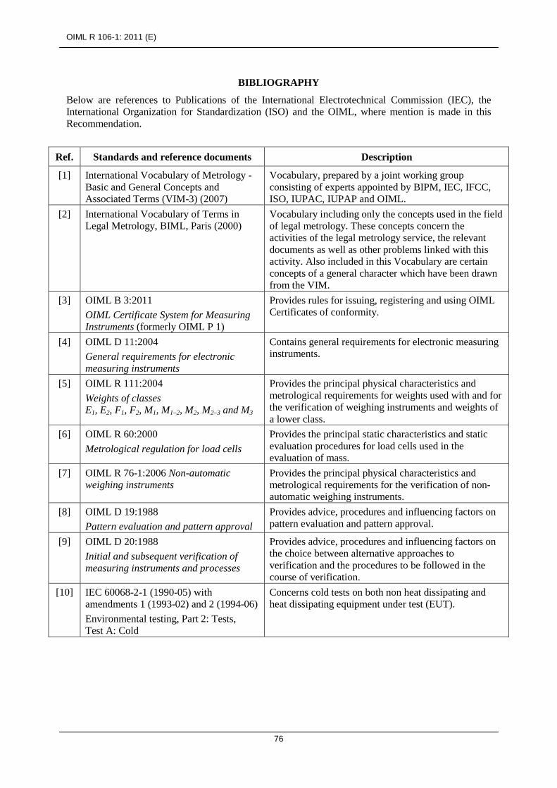
OIML R 106-1: 2011 (E)
76
BIBLIOGRAPHY
Below are references to Publications of the International Electrotechnical Commission (IEC), the International Organization for Standardization (ISO) and the OIML, where mention is made in this Recommendation.
Ref. Standards and reference documents Description
[1] International Vocabulary of Metrology -Basic and General Concepts and Associated Terms (VIM-3) (2007)
Vocabulary, prepared by a joint working group consisting of experts appointed by BIPM, IEC, IFCC, ISO, IUPAC, IUPAP and OIML.
[2] International Vocabulary of Terms in Legal Metrology, BIML, Paris (2000)
Vocabulary including only the concepts used in the field of legal metrology. These concepts concern the activities of the legal metrology service, the relevant documents as well as other problems linked with this activity. Also included in this Vocabulary are certain concepts of a general character which have been drawn from the VIM.
[3] OIML B 3:2011 OIML Certificate System for Measuring Instruments (formerly OIML P 1)
Provides rules for issuing, registering and using OIML Certificates of conformity.
[4] OIML D 11:2004 General requirements for electronic measuring instruments
Contains general requirements for electronic measuring instruments.
[5] OIML R 111:2004 Weights of classes E1, E2, F1, F2, M1, M1–2, M2, M2–3 and M3
Provides the principal physical characteristics and metrological requirements for weights used with and for the verification of weighing instruments and weights of a lower class.
[6] OIML R 60:2000 Metrological regulation for load cells
Provides the principal static characteristics and static evaluation procedures for load cells used in the evaluation of mass.
[7] OIML R 76-1:2006 Non-automatic weighing instruments
Provides the principal physical characteristics and metrological requirements for the verification of non-automatic weighing instruments.
[8] OIML D 19:1988 Pattern evaluation and pattern approval
Provides advice, procedures and influencing factors on pattern evaluation and pattern approval.
[9] OIML D 20:1988 Initial and subsequent verification of measuring instruments and processes
Provides advice, procedures and influencing factors on the choice between alternative approaches to verification and the procedures to be followed in the course of verification.
[10] IEC 60068-2-1 (1990-05) with amendments 1 (1993-02) and 2 (1994-06) Environmental testing, Part 2: Tests, Test A: Cold
Concerns cold tests on both non heat dissipating and heat dissipating equipment under test (EUT).
OIML R 106-1: 2011 (E)
77
Ref. Standards and reference documents Description
[11] IEC 60068-2-2 (2007-07) Ed. 5.0 Environmental testing Part 2: Tests, Test B: Dry heat
Contains test Ba : dry heat for non heat dissipating specimen with sudden change of temperature; test Bb dry heat for non heat dissipating specimen with gradual change of temperature; tests Bc : dry heat for heat dissipating specimen with sudden change of temperature; test Bd dry heat for heat dissipating specimen with gradual change of temperature.
[12] IEC 60068-3-1 (1974-01) + Supplement A (1978-01): Environmental testing Part 3 Background information, Section 1: Cold and dry heat tests
Gives background information for Tests A: Cold (IEC 68-2-1), and Tests B: Dry heat (IEC 68-2-2). Includes appendices on the effect of: chamber size on the surface temperature of a specimen when no forced air circulation is used; airflow on chamber conditions and on surface temperatures of test specimens; wire termination dimensions and material on surface temperature of a component; measurements of temperature, air velocity and emission coefficient. Supplement A - gives additional information for cases where temperature stability is not achieved during the test.
[13] IEC 60068-2-78 (2001-08) Environmental testing - Part 2-78: Tests - Test Cab: Damp heat, steady state (IEC 60068-2-78 replaces the following withdrawn standards: IEC 60068-2-3, test Ca and IEC 60068-2-56, test Cb)
Provides a test method for determining the suitability of electro-technical products, components or equipment for transportation, storage and use under conditions of high humidity. The test is primarily intended to permit the observation of the effect of high humidity at constant temperature without condensation on the specimen over a prescribed period. This test provides a number of preferred severities of high temperature, high humidity and test duration. The test can be applied to both heat-dissipating and non-heat dissipating specimens. The test is applicable to small equipment or components as well as large equipment having complex interconnections with test equipment external to the chamber, requiring a setup time which prevents the use of preheating and the maintenance of specified conditions during the installation period.
[14] IEC 60068-3-4 (2001-08) Environmental testing - Part 3-4: Supporting documentation and guidance - Damp heat tests
Provides the necessary information to assist in preparing relevant specifications, such as standards for components or equipment, in order to select appropriate tests and test severities for specific products and, in some cases, specific types of application. The object of damp heat tests is to determine the ability of products to withstand the stresses occurring in a high relative humidity environment, with or without condensation, and with special regard to variations of electrical and mechanical characteristics. Damp heat tests may also be utilized to check the resistance of a specimen to some forms of corrosion attack.

OIML R 106-1: 2011 (E)
78
Ref. Standards and reference documents Description
[15] IEC/TR 61000-2-1 (1990-05) Electromagnetic compatibility (EMC) Part 2: Environment Section 1
Electromagnetic compatibility (EMC) Part 2: Environment Section 1: Description of the environment- Electromagnetic environment for low-frequency conducted disturbances and signaling in public power supply systems.
[16] IEC 61000-4-1 (2006-10) Ed. 3.0 Basic EMC Publication Electromagnetic compatibility (EMC) Part 4: Testing and measurement techniques. Section 1: Overview of IEC 61000-4 series
Gives applicability assistance to the users and manufacturers of electrical and electronic equipment on EMC standards within the IEC 61000-4 series on testing and measurement techniques. Provides general recommendations concerning the choice of relevant tests.
[17] IEC 60654-2 (1979-01), with amendment 1 (1992-09) Operating conditions for industrial process measurement and control equipment - Part 2: Power
Gives the limiting values for power received by land-based and offshore industrial process measurement and control systems or parts of systems during operation.
[18] IEC 61000-4-11 (2004-03) Electromagnetic compatibility (EMC) Part 4-11: Testing and measuring techniques - Voltage dips, short interruptions and voltage variations immunity tests
Defines the immunity test methods and range of preferred test levels for electrical and electronic equipment connected to low-voltage power supply networks for voltage dips, short interruptions, and voltage variations. This standard applies to electrical and electronic equipment having a rated input current not exceeding 16 A per phase, for connection to 50 Hz or 60 Hz AC networks. It does not apply to electrical and electronic equipment for connection to 400 Hz AC networks. Tests for these networks will be covered by future IEC standards. The object of this standard is to establish a common reference for evaluating the immunity of electrical and electronic equipment when subjected to voltage dips, short interruptions and voltage variations. It has the status of a Basic EMC Publication in accordance with IEC Guide 107.
[19] IEC 61000-4-4 (2004-07) Electromagnetic compatibility (EMC) Part 4-4: Testing and measurement techniques - Electrical fast transient/burst immunity test
Establishes a common and reproducible reference for evaluating the immunity of electrical and electronic equipment when subjected to electrical fast transient/burst on supply, signal, control and earth ports. The test method documented in this part of IEC 61000-4 describes a consistent method to assess the immunity of an equipment or system against a defined phenomenon. The standard defines: test voltage waveform; range of test levels; test equipment; verification procedures of test equipment; test setup; and test procedure.
The standard gives specifications for laboratory and post-installation tests.

OIML R 106-1: 2011 (E)
79
Ref. Standards and reference documents Description
[20] IEC 61000-4-5 (2005-11) Ed. 2.0 Electromagnetic compatibility (EMC) - Part 4-5: Testing and measurement techniques - Surge immunity test
Relates to the immunity requirements, test methods, and range of recommended test levels for equipment to unidirectional surges caused by over-voltages from switching and lightning transients. Several test levels are defined which relate to different environment and installation conditions. These requirements are developed for and are applicable to electrical and electronic equipment. Establishes a common reference for evaluating the performance of equipment when subjected to high-energy disturbances on the power and inter-connection lines.
[21] IEC 61000-4-2 (2009) with amendment 1 (1998-01) and amendment 2 (2000-11) Consolidated Edition: IEC 61000-4-2 (2001-04) Ed. 1.2
Electromagnetic Compatibility (EMC) - Part 4: Testing and measurement techniques - Section 2: Electrostatic discharge immunity test. Basic EMC Publication.
[22] IEC 61000-4-3 (2008-04) Ed. 3.1 Electromagnetic Compatibility (EMC) - Part 4: Testing and measurement techniques - Section 3: Radiated, radio-frequency, electromagnetic field immunity test.
[23] IEC 61000-4-6 (2008-10) Ed. 3.0 Electromagnetic compatibility (EMC)
Part 4: Testing and measurement techniques. Section 6: Immunity to conducted disturbances, induced by radio-frequency fields
Relates to the conducted immunity requirements of electrical and electronic equipment to electromagnetic disturbances coming from intended radio-frequency (RF) transmitters in the frequency range 9 kHz up to 80 MHz. Equipment not having at least one conducting cable (such as mains supply, signal line or earth connection), which can couple the equipment to the disturbing RF fields is excluded. This standard does not intend to specify the tests to be applied to particular apparatus or systems. Its main aim is to give a general basic reference to all concerned product committees of the IEC. The product committees (or users and manufacturers of equipment) remain responsible for the appropriate choice of the test and the severity level to be applied to their equipment.