automatic software deployment in the azure cloud - inria · automatic software deployment in the...
TRANSCRIPT
HAL Id: hal-01061088https://hal.inria.fr/hal-01061088
Submitted on 5 Sep 2014
HAL is a multi-disciplinary open accessarchive for the deposit and dissemination of sci-entific research documents, whether they are pub-lished or not. The documents may come fromteaching and research institutions in France orabroad, or from public or private research centers.
L’archive ouverte pluridisciplinaire HAL, estdestinée au dépôt et à la diffusion de documentsscientifiques de niveau recherche, publiés ou non,émanant des établissements d’enseignement et derecherche français ou étrangers, des laboratoirespublics ou privés.
Distributed under a Creative Commons Attribution| 4.0 International License
Automatic Software Deployment in the Azure CloudJacek Cala, Paul Watson
To cite this version:Jacek Cala, Paul Watson. Automatic Software Deployment in the Azure Cloud. Frank Eliassen;Rüdiger Kapitza. 10th IFIP WG 6.1 International Conference on Distributed Applications and In-teroperable Systems (DAIS) / Held as part of International Federated Conference on DistributedComputing Techniques (DisCoTec), Jun 2010, Amsterdam, Netherlands. Springer, Lecture Notes inComputer Science, LNCS-6115, pp.155-168, 2010, Distributed Applications and Interoperable Sys-tems. <10.1007/978-3-642-13645-0_12>. <hal-01061088>
Automatic Software Deployment in the AzureCloud
Jacek Ca la and Paul Watson
School of Computing Science, Newcastle University,Newcastle upon Tyne, NE1 7RU, United Kingdom{jacek.cala, paul.watson}@newcastle.ac.uk
Abstract. For application providers, cloud computing has the advantagethat it reduces the administrative effort required to satisfy processing andstorage requirements. However, to simplify the task of building scalableapplications, some of the cloud computing platforms impose constraintson the application architecture, its implementation and tools that maybe used in development; Microsoft Azure is no exception.In this paper we show how an existing drug discovery system — DiscoveryBus — can benefit from Azure even though none of its components wasbuilt in the .Net framework. Using an approach based on the “Deploy-ment and Configuration of Component-based Applications Specfication”(D&C), we were able to assemble and deploy jobs that include differenttypes of process-based tasks. We show how extending D&C deploymentmodels with temporal and spatial constraints provided the flexibilityneeded to move all the compute-intensive tasks within the Discovery Busto Azure with no changes to their original code.
1 Introduction
The emergence of cloud execution environments shifts the management andaccess to computing and storage resources to a new, higher, and more efficientlevel. Often, however, it requires developers to rebuild or at least substantiallyre-engineer existing applications to meet new requirements. This is true forMicrosoft’s Azure cloud that was designed for applications based on the .Netframework, and which supports a specific, queue-based software architecture.For many existing software systems, whose development may have consumedsignificant resources, it could be prohibitively expensive to have to redesign andreimplement them to fit these constraints. Therefore, the key question for uswas whether it was possible for existing software to benefit from new executionenvironments such as the Azure Cloud without the need for significant, and soexpensive, changes.
This paper presents details of the automatic deployment platform we developedfor Azure, driven by the need of a chemistry application performing QSARanalysis. Quantitative Structure-Activity Relationship (QSAR) is a method usedto mine experimental data for patterns that relate the chemical structure of adrug to its activity. Predicting the properties of new structures requires significant
computing resources and we wanted to exploit the Windows Azure Cloud inorder to accelerate this process [7].
2 Motivation and Approach
The Discovery Bus is a multi-agent system that automates QSAR analysis.It implements a competitive workflow architecture that allows the exhaustiveexploration of molecular descriptor and model space, automated model validationand continuous updating as new data and methods are made available [3]. Ourmain goal was to move to Azure as much of the computing-intensive agents aspossible to make the most of the parallelization offered by the cloud. However,the key problem we encountered when moving Discovery Bus components toAzure was that none of them were created in the .Net framework. Instead, theywere written in the Java, C++, and R languages. Therefore, to be able to usethe Azure platform directly we needed a solution that would enable us to runand execute existing, non-.Net software in the cloud. For efficiency, and to reducethe amount of the software stack we need to maintain ourselves, this shouldideally be a solution that allows the deployment of only a Discovery Bus agentinstead of the whole OS stack including that agent, as in the Infrastructure as aService (IaaS) approach. Our aim was therefore to build an open and lightweightdeployment platform that can support a diverse set of existing Discovery Busagents running in Azure.
The Windows Azure platform is a combination of processing and storageservices. The compute services are divided into two types of nodes — web andworker role nodes. The web role enables the creation of applications based onASP.NET and WCF and is the entry point for external clients to any Azure-based application. In contrast, the worker role runs applications as independentbackground processes. To communicate, web and worker roles can use the Azurestorage service comprising of queue, table and blob storage. The primary meansof communication for Azure-based systems are queues. The queue-based approachaims at maximising scalability because many web role nodes can insert tasks toa queue, while many worker role nodes can acquire tasks from the queue. Bysimply increasing the number of workers, the tasks remaining in the queue canbe processed faster [10].
The proposed anycast-like operation model [1] fits very well problems that donot require much communication apart from a single request-response patternwith no state preserved in the workers. Much of the Discovery Bus processinghas this kind of communication style, but to use Azure for QSAR processing, themissing link is the ability to install and execute non-.Net components. Moreover,as these components often have specific prerequisites such as the availability ofthird-party libraries and a Java runtime environment, a deployment tool mustallow more sophisticated dependencies to be expressed.
We based our deployment solution on the “Deployment and Configuration ofComponent-based Distributed Applications Specification” (D&C) [11]. It defines

the model-based approach to deployment1 and is built according to the ModelDriven Architecture (MDA). D&C specifies a Platform Independent Model (PIM)of deployment which follows the general idea that the deployment process remainsthe same, independent of the underlying software implementation technology.The PIM can further be customized with Platform Specific Models (PSMs),such as PSM for CCM [12], to address aspects of deployment specific to aparticular software technology. The D&C specification defines one of the mostcomplete deployment standards [5], however, it originates from object-orientedand component-based domains, and PSM for CCM is the only existing PIM toPSM mapping. One of our intentions was to determine whether the deploymentapproach proposed by OMG can be used at a different virtualization level; inour case, a software component is usually an OS executable and a componentinstance is commonly a process in an operating system. This is in stark contrastto the definition of component proposed in the specification.
One of the key qualities of model-based deployment, which distinguishes itfrom the script-based and language-based approaches, is a separation between amodel of execution environment and model of software (Fig. 1). This improvesthe reusability of software and environment definitions as the same softwaredescription can be used for deployment over different execution environments,and the same environment description can be used for the deployment of differentsoftware. This separation is especially important for heterogeneous environmentswhere deployment planning enables the matching of software components toappropriate execution nodes. Previously, Azure offered one type of resource, butrecently Microsoft enabled four different computing node sizes in their cloudplatform. However, model-based deployment also provides the means to expressexecution node resources, which is crucial for planning deployments in multi-layervirtualized environments. The deployment of a component at a lower virtualizationlevel enriches the set of software resources, enabling further deployments at higherlevels. For example, if a Java runtime environment (JRE) is deployed on a nodeat the OS level, that node gains the ability to run Java applications. The JREcan be expressed as a node resource, which is then taken into account duringplanning. These advantages motivate the need for deployment planning, and themodel-based approach.
3 Architecture of the Automatic Deployment Solution
In order to make the most of the scalability offered by the Azure cloud, ourdeployment platform is a queue-based system that allows a web role to request thedeployment of jobs on worker nodes. For the purpose of the QSAR use case, jobsrepresent the code of Discovery Bus agents but our platform is generic and allowspotentially any kind of program to be run. Every job is described by a deploymentplan that defines what to install and execute. We extended models defined in theD&C specification with some of the concepts proposed in our previous work [2].A deployment plan can describe multiple tasks to be deployed, each of which may1 In contrast to the script-based and language-based approaches [6].

Application Model
Execution Environment Model
Fig. 1. Model-based deployment separates between software and execution environmentmodels.
be of different type such as Java-based applications, or Python and R scripts.The tasks can be deployed independently, or can be bound with spatial andtemporal dependencies. A deployment plan may also include dependencies onother plans that need to be enacted on first, e.g. Java-based applications thatrequire Java runtime to be available first.
The overall architecture of our system is shown in Fig. 2. Plans are submittedby a web role Controller to a common queue and can then be read by workers.A submitted plan is acquired by a single worker DeployerEngine that tries toinstall and execute the job. Once the execution is finished, the worker returnsresults to the Azure blob storage where they can be found by Controller.
<< Web Role >>
Controller
<< Worker Role >>
Deployer Engine
<< Worker Role >>
Deployer Engine
<< Worker Role >>
Deployer Engine
deployment plans
Queue Storage
job results
Blob Storage
Fig. 2. An illustration of the communication path between the web role Controller andworker role Deployers.
Usually, the Controller sends different types of jobs to the queue, while theDeployerEngine matches a job to an appropriate deployer class that can handle

it. To deal with the plans we distinguished two levels of deployers: operatingsystem level and process level. All of them realize the same interface IDeployer(Fig. 3). It follows a one-phase activation scenario, which is a slightly simplifiedversion of the two-phase activation proposed by D&C. The IDeployer interfaceincludes operations related to plan installation and activation, whereas the two-phase deployer also includes an intermediate, initialization step. The purposeof install is to collect together all artifacts required to activate the plan on thetarget node. The activate operation is responsible for running the plan, and itsbehavior heavily depends on the level of the implementing deployer. The meaningof deinstall and deactivate is to reverse install and activation respectively.
When implementing process-level deployers, we noticed that irrespectiveof the type of a job to be run (a Java class/jar, python or R script and astandalone executable) the install operation remains the same and only minorchanges are required in the activate operation. The changes are mainly relatedto running a different virtual machine executable or standalone exec and settingtheir parameters according to the configuration properties provided in the plan.Moreover, for all process-based components we distinguished exactly the sameinput and output ports: standard input, standard output and standard error.This unifies the way in which the results of job execution can be returned backto Controller.
Base Process Deployer
R Script Deployer
Exec Deployer
Python App Deployer
Java App Deployer
OS Library Deployer
<< realizes >>
<< realizes >>
<<interface>>
ITwoPhaseDeployer
+ initialize+ deinitialize
OS deployer level process deployer level
+ install+ deinstall+ activate+ deactivate
<<interface>>
IDeployer
Fig. 3. Class hierarchy showing relation between different types of deployers.
Conversely, implementation of OSLibraryDeployer differs from the otherssignificantly. The main task of this entity is to enable access to a requestedsoftware package for deployers at the higher-level. The idea is that OSLibrary-

Deployer installs a package and during activation exposes its contents as noderesources. We have implemented an automated plan generator that producesdeployment plans using manually prepared plan templates. Its main disadvantageis that it does not take node resources into account and treats all worker nodesequally irrespective of what resources they currently offer. However, in the futurewe would like to adapt this to search for node resources during the deploymentplanning phase and select the node which best fits a submitted plan.
4 Expressiveness of the Deployment Solution
One of the essential elements of the model-based deployment is expressiveness ofthe models that are used to describe the software and the execution environment.Although D&C defines one of the most complete deployment standards, wenoticed in our previous work [2] that there are some key aspects that thisspecification does not address. In particular, it lacks: modelling of multilayervirtualized systems, support for different software technologies, and the abilityto express temporal constraints on deployment actions.
In this section we present more details of how we adapted the platformindependent model of deployment proposed by the OMG to our needs. The firstimportant assumption is that in this work we address different virtualizationlevels than the one proposed in PSM for CCM. As mentioned above, a deploymentplan can include components of different types such as OS libraries, executablesand Python scripts. The key to map the D&C PIM to the virtualization levelsaddressed by our deployment engine was to notice that a component instancemay represent either a process or an installed and active OS library. This allowedus to develop the mapping for a deployment plan and all its elements. Table 1includes details of this mapping.
The main feature of the mapping presented here is the definition of a com-ponent interface. For the process level we defined a component as having threeports: input, output and error. Using these ports, components within a plan canbe connected together much like processes in an operating system shell. Moreover,they can be bound to external locations such as a URL or a blob in Azure storage.Fig. 4 depicts a sample plan comprising two tasks that run concurrently. Theysend their error streams to a common blob; Task1 sends its output stream toTask2 and to an external URL. Also, it acquires input from an external location.As shown in the figure, at the process virtualization level, deployment plansthat represent a composite component, also have the three ports mentioned.This allowed us to unify the way in which the results of process-based jobs arereturned. By default, the outcome of a deployment plan is two blobs: outputand error. Any component in a plan can be bound to these ports, which meansthat contents of their outputs are redirected appropriately. It is also possible toredirect ports of multiple tasks to a single output and redirect a single output tomultiple locations.
At the process virtualization level, different components can also be combinedtogether in a single plan using temporal and spatial constraints (Fig. 5). Temporal
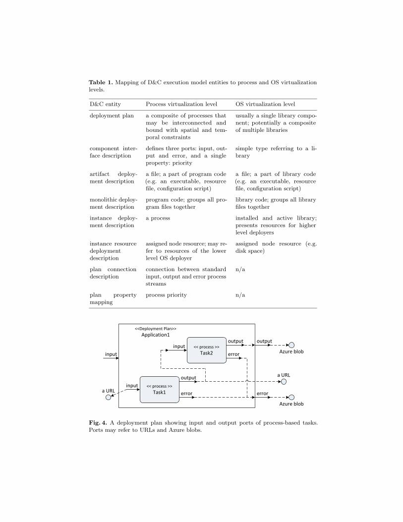
Table 1. Mapping of D&C execution model entities to process and OS virtualizationlevels.
D&C entity Process virtualization level OS virtualization level
deployment plan a composite of processes thatmay be interconnected andbound with spatial and tem-poral constraints
usually a single library compo-nent; potentially a compositeof multiple libraries
component inter-face description
defines three ports: input, out-put and error, and a singleproperty: priority
simple type referring to a li-brary
artifact deploy-ment description
a file; a part of program code(e.g. an executable, resourcefile, configuration script)
a file; a part of library code(e.g. an executable, resourcefile, configuration script)
monolithic deploy-ment description
program code; groups all pro-gram files together
library code; groups all libraryfiles together
instance deploy-ment description
a process installed and active library;presents resources for higherlevel deployers
instance resourcedeploymentdescription
assigned node resource; may re-fer to resources of the lowerlevel OS deployer
assigned node resource (e.g.disk space)
plan connectiondescription
connection between standardinput, output and error processstreams
n/a
plan propertymapping
process priority n/a
<< process >>
Task1input
output
error
<<Deployment Plan>>
Application1
<< process >>
Task2input
output
error
output
error
input
a URL
a URL
Azure blob
Azure blob
Fig. 4. A deployment plan showing input and output ports of process-based tasks.Ports may refer to URLs and Azure blobs.

constraints allow the expression of component dependencies that are usuallymodelled in the form of a direct acyclic graph. The StartToStart and Finish-ToFinish collocations enable synchronization barriers to be created betweencomponents’ deployment activities, whereas FinishToStart allows instances tobe linked in a deployment chain. We also adapted the original D&C spatial con-straints2 to the process virtualization level. Instead of SameProcess/Different-Process, the SpatialConstraintKind allows the expression of the need forrunning selected processes in the same or different working directories. This maybe useful when components within a plan have some implicit dependencies. Forexample, if they use common input files, they may need to run in the samedirectory. Conversely, when they produce result files with the same names, theyneed to execute in separate working directories.
<< Planner >>
Instance Deployment Description
+constrainedInstance1..*
+constrainedInstance1..*
<< Planner >>
PlanTemporalConstraint
+ constraint : TemporalConstraintKind
<< Planner >>
PlanSpatialConstraint
+ constraint : SpatialConstraintKind
<< enumeration >>
SpatialConstraintKind
+ SameNode+ DifferentNode+ SameDirectory+ DifferentDirectory+ NoConstraint
<< enumeration >>
TemporalConstraintKind
+ StartToStart+ FinishToStart+ FinishToFinish
Fig. 5. Temporal and spatial constraints in the proposed deployment model.
The last element of the proposed mapping is related to resources assignedto deployed components. We made a separation between the lower level, OSdeployer and higher level, process deployers. Our intention is that when theOS deployer activates a library on a node, it also registers a set of resourcesassociated with that library. This will enable a deployment planer, working at theprocess virtualization level, to search for the best node to deploy. For example,if a node executed a Java-based application previously, it has a JRE deployed.Therefore, any subsequent Java-based components should preferably be deployedon this node instead of any other that does not provide any JRE. Although wedo not address deployment planning yet and use manually prepared deploymentplans, our platform is well suited for this.
2 i.e. PlanLocality and PlanLocalityKind entities.

5 Application of Our Deployment Solution to DiscoveryBus
Discovery Bus is a system that implements the competitive workflow architectureas a distributed, multi-agent system. It exhaustively explores the available modeland descriptor space, which demands a lot of computing resources [3]. Fortunately,the architecture of Discovery Bus makes it easy to move agents to differentlocations in a distributed environment. This enabled us to place the most compute-intensive agents in the cloud. However, as agents are not limited to any particularimplementation technology, the key requirement for our deployment platformwas to support different software technologies. These include Java, R and nativeapplications.
Our platform can deploy arbitrary jobs, however, for the purpose of the QSARuse case we prepared a number of predefined deployment plans that describespecific Discovery Bus agents. One of the most compute-intensive tasks is thecalculation of the molecular descriptors. Figure 6 shows a deployment plan thatwe designed to run this job in Azure. First, the plan expresses a dependency onthe JRE and CDK libraries. These dependencies are directed to the lower level,OS deployer that installs and activates them on an Azure worker node. Second,the plan includes an artifact description for the input data file which is providedto the descriptor calculator task on its activation. The location of this artifact isgiven when the plan is created. Third, the calculate descriptor program sendsresults to the standard output stream, which we redirect to the external outputport of the plan. By default, the output of a deployment plan is stored in theAzure blob storage. Similarly, the error stream of the task is redirected to theexternal error port and is transmitted to the blob storage.
<< Java app >>
Calculate CDK Descriptors
output
error
output
error
<< OS library >>
Java Runtime Environment
<< depends on >>
<< OS library >>
CDK Library
<< DeploymentPlan >>
CalculateCDKDescriptorsAgent
<< Artifact >>
InputFile
Fig. 6. A deployment plan created for a selected, Java-based Discovery Bus agent.
This example shows how easy it is to prepare a suitable deployment plan foran existing application. However, there are many cases when a process-based taskreturns results not only via standard output or error streams but creates files,or communicates results through a network. Neither our approach, nor Azure,
prevents sending data via a network, but the more difficult case occurs whenthe task execution produces files. As they are stored in local worker storage, wesupplemented the deployment plan with a post-processing task that was able totransfer them to a desired location.
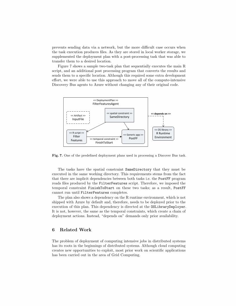
Figure 7 shows a sample two-task plan that sequentially executes the main Rscript, and an additional post processing program that converts the results andsends them to a specific location. Although this required some extra developmenteffort, we were able to use this approach to move all of the compute-intensiveDiscovery Bus agents to Azure without changing any of their original code.
<< R script >>
FilterFeatures
<< Generic app >>
PostFF<< temporal constraint >>
FinishToStart
<< OS library >>
R Runtime Environment
<< spatial constraint >>
SameDirectory<< Artifact >>
InputFile
<< DeploymentPlan >>
FilterFeaturesAgent
<< depends on >>
Fig. 7. One of the predefined deployment plans used in processing a Discover Bus task.
The tasks have the spatial constraint SameDirectory that they must beexecuted in the same working directory. This requirements stems from the factthat there are implicit dependencies between both tasks i.e. the PostFF programreads files produced by the FilterFeatures script. Therefore, we imposed thetemporal constraint FinishToStart on these two tasks; as a result, PostFFcannot run until FilterFeatures completes.
The plan also shows a dependency on the R runtime environment, which is notshipped with Azure by default and, therefore, needs to be deployed prior to theexecution of this plan. This dependency is directed at the OSLibraryDeployer.It is not, however, the same as the temporal constraints, which create a chain ofdeployment actions. Instead, “depends on” demands only prior availability.
6 Related Work
The problem of deployment of computing intensive jobs in distributed systemshas its roots in the beginnings of distributed systems. Although cloud computingcreates new opportunities to exploit, most prior work on scientific applicationshas been carried out in the area of Grid Computing.

Condor3 is one of the main examples of Grid-like environments that providebatch execution over distributed systems. It is a specialized workload managementsystem for compute-intensive jobs. Serial or parallel jobs submitted to Condorare placed in a queue and decisions are made on when and where to run thejobs based on a scheduling policy. Execution progress is then monitored untilcompletion. To match jobs to the most appropriate resources (compute nodes)Condor uses the ClassAd mechanism, which is a flexible and expressive frameworkfor matching resource requests (jobs) with resource offers (machines). Jobs canstate both job requirements and preferences, while compute nodes can specifyrequirements and preferences about the jobs they are willing to run. All of thesemay be described through expressions, allowing a broad range of policies to beimplemented [9].
There are three key differences between Condor and our solution. First,Condor uses the ClassAd mechanism and a central manager to schedule jobs,whereas Azure proposes, and we use, the queue-based approach for scalability.However, Condor supports a flexible matching of jobs to resources, while wetreat all computing resources as being indistinguishable. We leave the problem ofresource discovery and deployment planning for future work. Second, the abilityto express dependencies between deployment plans such as between an R scriptand its execution environment allows for the clear and concise definition of jobprerequisites. This simplifies complex deployment in distributed environments,and is not supported by Condor. Third, we based our solution on D&C deploymentmodels that provide the recursive definition of a component which either can bea monolith or an assembly of subcomponents. Condor instead uses the ClassAdmechanism that describes a job without any relationship to others, except wheretemporal constraints are expressed by directed acyclic graphs and evaluated bythe DAGMan scheduler.4 We believe that temporal constraints are an importantfeature in a deployment plan and therefore supplemented D&C models to enabletheir definition. Condor does not support more sophisticated constraints, such asthe resources required to realize a connection between executing jobs. Neither dowe currently consider this aspect of D&C models, but we expect to extend oursystem to use it in the near future work.
The Neudesic Grid Computing Framework (Neudesic GCF)5 is dedicated tothe Azure platform. It provides a solution template and base classes for loading,executing, and aggregating grid tasks on the Microsoft cloud. Neudesic GCF offersa set of templates such as Worker, Loader and Aggregator. A Worker implementseach of the computing tasks, a Loader is added to read input data from localresources and generate tasks, and an Aggregator receives results and storesthem. Unlike with our solution, Neudesic GCF requires building applicationsfrom scratch. A developer is given a set of templates that they can use forprogramming, but as everything needs to be built in .Net, this framework was notsuitable for our use case. Moreover, the Neudesic GCF assumes the homogeneity
3 http://www.cs.wisc.edu/condor4 http://www.cs.wisc.edu/condor/dagman5 http://azuregrid.codeplex.com

of Azure resources as all workers are identical. With the use of model-baseddeployment, our solution is better prepared to be extended to take into accountof heterogeneous Azure computing resources. Several Cloud computing solutionsare available apart from Azure. The most prominent ones are the Google AppEngine (GAE) and the Amazon Elastic Computing Cloud (Amazon EC2).
The Google App Engine6 is a cloud computing platform primarily dedicatedto Python and Java language applications. It provides a high-level platform forrunning distributed systems and has the built-in ability to automatically scale thenumber of working nodes following changes in the incoming workload. However,unlike Microsoft Azure, this environment is closed with respect to running nativeprograms, which would require us to rewrite the existing code. Moreover, as itis aimed at building scalable web servers, GAE limits the time for processinga request to 30 seconds7 which makes it unsuitable for scientific computationin general and our QSAR scenario in particular, as this often needs much moretime to complete a single job.
Amazon EC28 provides a virtual computing environment controlled through aweb service interface. It gives complete control over the operating system installedon a computing node, which makes it more open than Azure [8]. However, as aresult, it demands more administrative and management effort, whereas Azurecan adopt a declarative approach to configuration through simple configurationdescriptors. Despite the fact that our solution is based on Azure, we believethat it could be ported to Amazon EC2 as well, providing the same benefits ofdeployment automation as for Azure.
RightScale9 offers a range of products that can run on top of different cloudplatforms such as Amazon EC2, Rackspace, FlexiScale. RightScale’s Grid Editionframework (GE framework) provides a queue-based solution for running batchprocesses. Overall, it follows similar pattern that we use. Additionally, the GEframework enables auto-scaling that can adapt the number of worker nodesin response to changing factors. The key difference between RightScale’s GEframework and our deployment solution is in the granularity of workers. TheGE framework as a basic unit of deployment uses server templates. A servertemplate is a preconfigured image of an operating system that is used to launchnew server instances in the Cloud. For each particular task or set of tasks auser needs to prepare an appropriate server template. Instead, in our approach abasic unit of deployment is a process-level component that is much smaller whencomparing to an OS image. Our deployment platform allows running arbitraryjobs on any active worker irrespective of which type of job it is.10 This promotesbetter resource sharing and guarantees more effective solution, especially for6 http://code.google.com/appengine7 See Google App Engine Documentation (ver. 2009-12-15) Sect. What Is Google App
Engine; Quotas and Limits.8 http://aws.amazon.com/ec29 http://www.rightscale.com
10 Currently this is any kind of task from a supported set of task types: a Windowsexecutable, a Java jar/class file, an R script, a Python script or a command-linescript.

smaller and short running tasks. Moreover, our deployment plans can includemany interrelated subtasks, which results in a much more expressive frameworkand enables the assembling of applications from existing components.
7 Conclusions and Future Work
In this paper we discuss an automatic deployment framework for the Azure cloudplatform. We use the framework to run compute-intensive Discovery Bus agentsin the cloud. Despite the fact that none of the Bus components was implementedin the .Net framework, our framework allowed us to seamlessly integrate mostexisting agents with Azure without any code modification. The exception was forthose agents that produced results in the local file system. Here, some additionaldevelopment effort was required; we had to implement a simple task to transferoutput files to a designated location. Then, using our deployment platform wecould express spatial and temporal constraints between processes so ensuringthat all the results produced are correctly transmitted.
Apart from results specifically focussed on the Discovery Bus as a motivatingscenario, this work showed that the platform independent model defined in theD&C specification can be successfully applied to the process and OS virtual-ization levels. The PIM creates a very expressive deployment framework thatwith only minor modifications allowed us to build composite deployment plansdescribing process-based applications. Further, the ability to express dependenciesbetween deployment plans supports the clear and concise definition of componentprerequisites.
By using the proposed deployment framework we were able to successfullyrun Discovery Bus agents in Azure. To generalise the solution, we see threemajor directions for future work. Firstly, we would like to support the two-phaseinitialization of process-based components. This will enable us to distributecomponents included in a deployment plan over multiple worker nodes even inthe case when components are interconnected. Secondly, we see the need fordeployment planning to make our solution more effective. The ability to determinenode resources would allow the matching of work to those nodes that best fit thesubmitted plan. However, our major focus remains on preserving efficient scalabil-ity for a queue-based system, while enabling resource discovery and deploymentplanning (an interesting approach to this problem is presented in [4]). Finally,an interesting future direction for our framework is the dynamic deployment ofnew deployer types. If our DeployerEngine implements the IDeployer interface,we can dynamically install and activate deployers that support new componenttypes. This in turn will increase flexibility and facilitate the runtime evolution ofthe deployment platform according to changing needs.
Acknowledgements We would like to thank Microsoft External Research forfunding this work. Also, we are grateful to the wider team working on the project:the Discovery Bus team (David Leahy, Vladimir Sykora and Dominic Searson),the e-Science Central Team (Hugo Hiden, Simon Woodman) and Martin Taylor.

References
1. Abley, J., Lindqvist, K.: Operation of Anycast Services. Request for Comments4786, Best Current Practice 126 (2006)
2. Cala, J.: Adaptive Deployment of Component-based Applications in Distributed Sys-tems. PhD thesis, AGH-University of Science and Technology, Krakow (submittedFeb. 2010)
3. Cartmell J., Enoch, S., Krstajic, D., Leahy, D.E.: Automated QSPR throughCompetitive Workflow. Journal of Computer-Aided Molecular Design, 19: 821–833(2005)
4. Castro, M., Druschel, P., Kermarrec, A.-M., Rowstron, A.: Scalable Application-Level Anycast for Highly Dynamic Groups. Networked Group Communication.LNCS 2816, 47–57 (2003)
5. Dearle, A.: Software Deployment, Past, Present and Future. FOSE’07: 2007 Futureof Software Engineering, 269-284, IEEE Computer Society (2007)
6. Talwar, V., Milojicic, D., Wu, Q., Pu, C., Yan, W., Jung, G.: Approaches for ServiceDeployment. IEEE Internet Computing, 9(2):70–80 (2005)
7. Watson, P., Hiden, H., Woodman, S., Ca la, J., Leahy D.: Drug Discovery on theAzure Cloud. Poster presentation on Microsoft e-Science Workshop, Pittsburgh(2009)
8. Amazon Web Services LLC, Amazon Elastic Compute Cloud: User Guide; APIVersion 2009-11-30 (2010)
9. Condor Team: Condor Version 7.5.0 Manual. University of Wisconsin-Madison(2010)
10. Microsoft Corp.: Windows Azure Queue — Programming Queue Storage. Whitepa-per (2008)
11. Object Management Group, Inc.: Deployment and Configuration of Component-based Distributed Applications Specification; Version 4.0 (2006)
12. Object Management Group, Inc.: Common Object Request Broker Architecture(CORBA) Specification, Version 3.1; Part 3: CORBA Component Model (2008)