automatic standby unit modi
DESCRIPTION
Automatic standby unit MODITRANSCRIPT
Automatic standby unit
Modi

www.oez.com

ModiAutomatic standby unit
CONTENTS
DESCRIPTION...........................................................................................................................................................................................2
COMPOSITION OF TYPE DESIGNATION.................................................................................................................................................3
FUNCTIONS AND MODES........................................................................................................................................................................4
TIME DIAGRAMS......................................................................................................................................................................................6
SPECIFICATIONS....................................................................................................................................................................................10
EQUIPMENT OF CIRCUIT BREAKERS..................................................................................................................................................10
TYPE DESIGNATION OF CIRCUIT BREAKER ARION WL.....................................................................................................................11
DETERMINATION OF MECHANICAL INTERLOCKING OF CIRCUIT BREAKERS �������..............................................................11
WIRING DIAGRAM / DIAGRAM...........................................................................................................................................................12
DIMENSIONS.........................................................................................................................................................................................20
Connecting for BC160 ZA-0x-7xxx...................................................................12
Connecting for BD250 and BH630 ZA-0x-7xxx...................................................................13
Connecting for BL ZA-0x-8xxx....................................................................14
Connecting for ARION WL ZA-0x-6xxx...................................................................15
Connecting for BC160 with longitudinal coupling ZA-1x-7xxx...................................................................16
Connecting for BD250 and BH630 with longitudinal coupling ZA-1x-7xxx...................................................................17
Connecting for BL with longitudinal coupling ZA-1x-8xxx...................................................................18
Connecting for ARION WL with longitudinal coupling ZA-1x-6xxx...................................................................19
Modi
2
Automatic standby unit
DESCRIPTION
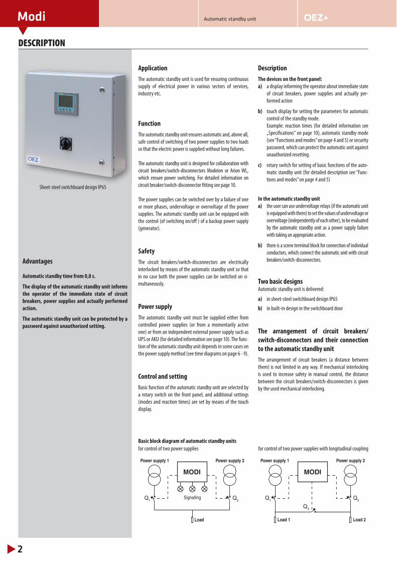
Application
The automatic standby unit is used for ensuring continuous
supply of electrical power in various sectors of services,
industry etc.
Function
The automatic standby unit ensures automatic and, above all,
safe control of switching of two power supplies to two loads
so that the electric power is supplied without long failures.
The automatic standby unit is designed for collaboration with
circuit breakers/switch-disconnectors Modeion or Arion WL,
which ensure power switching. For detailed information on
circuit breaker/switch-disconnector fi tting see page 10.
The power supplies can be switched over by a failure of one
or more phases, undervoltage or overvoltage of the power
supplies. The automatic standby unit can be equipped with
the control (of switching on/off ) of a backup power supply
(generator).
Safety
The circuit breakers/switch-disconnectors are electrically
interlocked by means of the automatic standby unit so that
in no case both the power supplies can be switched on si-
multaneously.
Power supply
The automatic standby unit must be supplied either from
controlled power supplies (or from a momentarily active
one) or from an independent external power supply such as
UPS or AKU (for detailed information see page 10). The func-
tion of the automatic standby unit depends in some cases on
the power supply method (see time diagrams on page 6 - 9).
Control and setting
Basic function of the automatic standby unit are selected by
a rotary switch on the front panel, and additional settings
(modes and reaction times) are set by means of the touch
display.
Description
The devices on the front panel:
a) a display informing the operator about immediate state
of circuit breakers, power supplies and actually per-
formed action
b) touch display for setting the parameters for automatic
control of the standby mode.
Example: reaction times (for detailed information see
„Specifi cations“ on page 10), automatic standby mode
(see “Functions and modes” on page 4 and 5) or security
password, which can protect the automatic unit against
unauthorized resetting.
c) rotary switch for setting of basic functions of the auto-
matic standby unit (for detailed description see “Func-
tions and modes” on page 4 and 5)
In the automatic standby unit
a) the user can use undervoltage relays (if the automatic unit
is equipped with them) to set the values of undervoltage or
overvoltage (independently of each other), to be evaluated
by the automatic standby unit as a power supply failure
with taking an appropriate action.
b) there is a screw terminal block for connection of individual
conductors, which connect the automatic unit with circuit
breakers/switch-disconnectors.
Two basic designsAutomatic standby unit is delivered:
a) in sheet-steel switchboard design IP65
b) in built-in design in the switchboard door
The arrangement of circuit breakers/
switch-disconnectors and their connection
to the automatic standby unit
The arrangement of circuit breakers (a distance between
them) is not limited in any way. If mechanical interlocking
is used to increase safety in manual control, the distance
between the circuit breakers/switch-disconnectors is given
by the used mechanical interlocking.
Sheet-steel switchboard design IP65
Advantages
Automatic standby time from 0,8 s.
The display of the automatic standby unit informs
the operator of the immediate state of circuit
breakers, power supplies and actually performed
action.
The automatic standby unit can be protected by a
password against unauthorized setting.
Basic block diagram of automatic standby units
Power supply 1 Power supply 2
Load
SignallingQ1 Q2
MODI
Power supply 1 Power supply 2
Load 1 Load 2
Q1 Q2
Q3
MODI
for control of two power supplies for control of two power supplies with longitudinal coupling
Modi
3
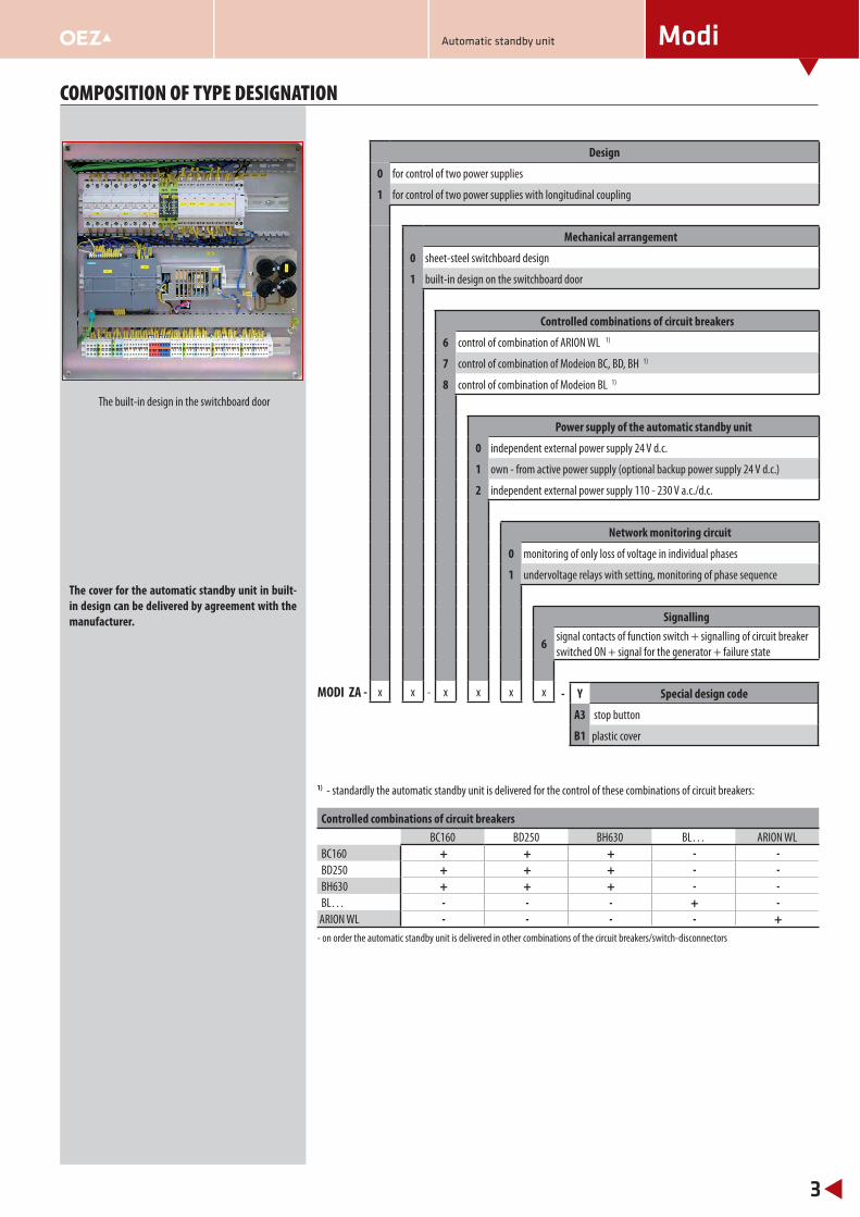
COMPOSITION OF TYPE DESIGNATION
The built-in design in the switchboard door
The cover for the automatic standby unit in built-
in design can be delivered by agreement with the
manufacturer.
1) - standardly the automatic standby unit is delivered for the control of these combinations of circuit breakers:
Design
0 for control of two power supplies
1 for control of two power supplies with longitudinal coupling
Mechanical arrangement
0 sheet-steel switchboard design
1 built-in design on the switchboard door
Controlled combinations of circuit breakers
6 control of combination of ARION WL 1)
7 control of combination of Modeion BC, BD, BH 1)
8 control of combination of Modeion BL 1)
Power supply of the automatic standby unit
0 independent external power supply 24 V d.c.
1 own - from active power supply (optional backup power supply 24 V d.c.)
2 independent external power supply 110 - 230 V a.c./d.c.
Network monitoring circuit
0 monitoring of only loss of voltage in individual phases
1 undervoltage relays with setting, monitoring of phase sequence
Signalling
6signal contacts of function switch + signalling of circuit breaker
switched ON + signal for the generator + failure state
MODI ZA - x x - x x x x
- on order the automatic standby unit is delivered in other combinations of the circuit breakers/switch-disconnectors
- Y Special design code
A3 stop button
B1 plastic cover
Controlled combinations of circuit breakers
BC160 BD250 BH630 BL… ARION WL
BC160 + + + - - BD250 + + + - - BH630 + + + - - BL… - - - + -
ARION WL - - - - +
Automatic standby unit
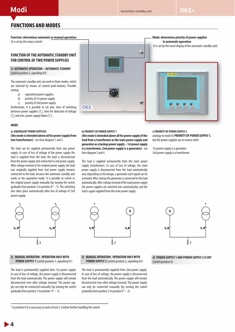
Function: determines automatic or manual operation
(it is set by the rotary switch)
FUNCTION OF THE AUTOMATIC STANDBY UNIT
FOR CONTROL OF TWO POWER SUPPLIES
1) AUTOMATIC OPERATION – AUTOMATIC STANDBY
(switch position 3, signalling H3)
The automatic standby unit can work in three modes, which
are selected by means of control push-buttons. Possible
setting:
a) equivalent power supplies
b) priority of 1st power supply
c) priority of 2nd power supply
furthermore, it is possible to set min. time of switching
between power supplies (T2), time for detection of voltage
(T3) and min. power supply failure (T
1) .
MODE
a) EQUIVALENT POWER SUPPLIES
(the mode is intended above all for power supply from
two transformers) - see time diagram 1 and 2
The load can be supplied permanently from any power
supply. In case of loss of voltage of the power supply the
load is supplied from the load, the load is disconnected
from the power supply and connected to 2nd power supply.
After voltage renewal of the original power supply, the load
was originally supplied from 2nd power supply remains
connected to the load, because the automatic standby unit
works in the equivalent mode. It is possible to switch to
the original power supply manually (by turning the switch
gradually from position 3 to position 01) – 3). The switching
also takes place automatically after loss of voltage of 2nd
power supply.
Modi
4
Automatic standby unit
FUNCTIONS AND MODES
2) MANUAL OPERATION - OPERATION ONLY WITH
POWER SUPPLY 1 (switch position 1, signalling H1)
The load is permanently supplied from 1st power supply.
In case of loss of voltage, the power supply is disconnected
from the load automatically. The power supply will remain
disconnected even after voltage renewal. The power sup-
ply can only be connected manually (by turning the switch
gradually from position 1 to position 01) – 1).
3) MANUAL OPERATION - OPERATION ONLY WITH
POWER SUPPLY 2 (switch position 2, signalling H2)
The load is permanently supplied from 2nd power supply.
In case of loss of voltage, the power supply is disconnected
from the load automatically. The power supply will remain
disconnected even after voltage renewal. The power supply
can only be connected manually (by turning the switch
gradually from position 2 to position 01) – 2).
4) POWER SUPPLY 1 AND POWER SUPPLY 2 IS OFF
(switch position 0)
T
G
QG QT
Z
T
G
QGQT
Z
T1
QT1
T2
QT2
Z
1) in position 0 it is necessary to wait at least 2 s before further handling the switch
b) PRIORITY OF POWER SUPPLY 1
(the mode is intended above all for power supply of the
load from a transformer as the main power supply and
generator as a backup power supply – 1st power supply
is a transformer, 2nd power supply is a generator) - see
time diagram 3 and 4
The load is supplied permanently from the main power
supply (transformer). In case of loss of voltage, the main
power supply is disconnected from the load automatically
and, depending on the design, a generator start signal can be
activated. After startup the generator is connected to the load
automatically. After voltage renewal of the main power supply
the power supplies are switched over automatically, and the
load is again supplied from the main power supply.
Mode: determines priority of power supplies
in automatic operation
(it is set by the touch display of the automatic standby unit)
c) PRIORITY OF POWER SUPPLY 2
analogy to mode b) PRIORITY OF POWER SUPPLY 1,
but the power supplies are in reverse order
1st power supply is a generator
2nd power supply is a transformer

Modi
5
Automatic standby unit
FUNCTIONS AND MODES
FUNCTION OF THE AUTOMATIC STANDBY UNIT
FOR CONTROL OF TWO POWER SUPPLIES
WITH LONGITUDINAL COUPLING
1) AUTOMATIC OPERATION – AUTOMATIC STANDBY
(switch position 6, signalling H6)
The automatic standby unit can work in three modes, which are selected by means of the touch display of the automatic standby unit. Possible setting:
a) standby for both power suppliesb) standby for 1st power supplyc) standby for 2nd power supply
furthermore, it is possible to set min. time of switching between power supplies (T
2), time for detection of voltage
(T3) and power supply failure (T
1).
MODE:
a) EQUIVALENT
Both loads can be supplied permanently from any power
supply. In case of loss of voltage of the power supply, the load
is disconnected from the power supply and connected (via
coupling closing) to 2nd power supply. After voltage renewal
of the original power supply, the coupling opens, and the
load is connected to the original power supply.
2) MANUAL OPERATION - BOTH POWER SUPPLY 1 AND
POWER SUPPLY 2 ARE OFF (switch position 0)
b) STANDBY FOR POWER SUPPLY 1
1st load can be supplied from 1st power supply or 2nd power
supply. 2nd load can only be supplied from 2nd power
supply. In case of loss of voltage of 1st power supply, 1st
load is disconnected from 1st power supply, and connected
to 2nd power supply (via coupling closing). After voltage
renewal of 1st power supply the coupling opens and 1st load
is connected to 1st power supply. In case of loss of voltage of
2nd power supply, 2nd load is disconnected from 2nd power
supply. 2nd load remains without voltage for the time of 2nd
power supply failure. No standby is carried out (the coupling
does not close).
c) STANDBY FOR POWER SUPPLY 2
2nd load can be supplied from 1st power supply or 2nd
power supply. 1st load can only be supplied from 1st power
supply. In case of loss of voltage of 2nd power supply, 2nd
load is disconnected from 2nd power supply, and connected
to 1st power supply (via coupling closing). After voltage
renewal of 2nd power supply the coupling opens and 2nd
load is connected to 2nd power supply. In case of loss of
voltage of 1st power supply 1st load is disconnected from
1st power supply. 1st load remains without voltage for the
time of 1st power supply failure. No standby is carried out
(the coupling does not close).
3) MANUAL OPERATION - OPERATION ONLY WITH
POWER SUPPLY 1 (switch position 1, signalling H1)
Only the 1st load is supplied permanently from 1st power
supply. In case of loss of voltage, the power supply is
disconnected from the load automatically. The power supply
will remain disconnected even after voltage renewal. The
power supply can only be connected manually (by turning
the switch gradually from position 1 to position 01) – 1 ).
4) MANUAL OPERATION - OPERATION ONLY WITH
POWER SUPPLY 2 (switch position 2, signalling H2)
Only 2nd load is supplied permanently from 2nd power
supply. In case of loss of voltage, the power supply is
disconnected from the load automatically. The power supply
will remain disconnected even after voltage renewal. The
power supply can only be connected manually (by turning
the switch gradually from position 2 to position 01) – 2 ).
5) MANUAL OPERATION - OPERATION ONLY WITH
POWER SUPPLY 1 WITH CLOSED COUPLING
(switch position 3, signalling H3)
Both loads are permanently supplied from 1st power supply.
In case of loss of voltage, the power supply is disconnected
from the loads automatically. The power supply will remain
disconnected even after voltage renewal. The power supply
can only be connected manually (by turning the switch
gradually from position 3 to position 01) – 3 ).
6) MANUAL OPERATION - OPERATION ONLY WITH
POWER SUPPLY 2 WITH CLOSED COUPLING
(switch position 4, signalling H4)
Both loads are permanently supplied from 2nd power supply.
In case of loss of voltage, the power supply is disconnected
from the loads automatically. The power supply will remain
disconnected even after voltage renewal. The power supply
can only be connected manually (by turning the switch
gradually from position 4 to position 01) – 4 ).
7) MANUAL OPERATION – OPERATION WITH BOTH
POWER SUPPLIES
(switch position 5, signalling H5)
1st load is permanently supplied from 1st power supply.
2nd load is permanently supplied from 2nd power supply.
In case of loss of voltage, the power supply is disconnected
from the load automatically. The power supply will remain
disconnected even after voltage renewal. The power supply
can only be connected manually (by turning the switch
gradually from position 5 to position 01) – 5 ).
1) – in position 0 it is necessary to wait at least 2 s before further handling the switch
Circuit breaker of 2nd power supply Q1
Longitudinal coupling switch Q3
Circuit breaker of 1st power supply Q2
0
0
0
0
0
1
0
1
1
1
0
0
1
0
1
1
1
0
Power supply 1 Power supply 2
Load 1 Load 2
Q1 Q2
Q3
MODI
Table of logic states of circuit breakers
Modi
6
Automatic standby unit
TIME DIAGRAMS
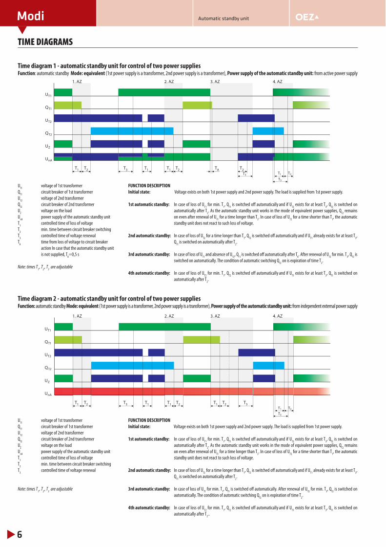
Time diagram 1 - automatic standby unit for control of two power suppliesFunction: automatic standby Mode: equivalent (1st power supply is a transformer, 2nd power supply is a transformer), Power supply of the automatic standby unit: from active power supply
UT1
voltage of 1st transformer
QT1
circuit breaker of 1st transformer
UT2
voltage of 2nd transformer
QT2
circuit breaker of 2nd transformer
UZ voltage on the load
UnA
power supply of the automatic standby unit
T1 controlled time of loss of voltage
T2 min. time between circuit breaker switching
T3 controlled time of voltage renewal
TA time from loss of voltage to circuit breaker
action In case that the automatic standby unit
is not supplied, TA=0,5 s
Note: times T1
, T2
, T3 are adjustable
FUNCTION DESCRIPTION
Initial state: Voltage exists on both 1st power supply and 2nd power supply. The load is supplied from 1st power supply.
1st automatic standby: In case of loss of UT1
for min. T1, Q
T1 is switched off automatically and if U
T2 exists for at least T
3, Q
T2 is switched on
automatically after T2. As the automatic standby unit works in the mode of equivalent power supplies, Q
T2 remains
on even after renewal of UT1
for a time longer than T3. In case of loss of U
T2 for a time shorter than T
1, the automatic
standby unit does not react to such loss of voltage.
2nd automatic standby: In case of loss of UT2
for a time longer than T1, Q
T2 is switched off automatically and if U
T1 already exists for at least T
3,
QT1
is switched on automatically after T2.
3rd automatic standby: In case of loss of UT1
and absence of UT2
, QT1
is switched off automatically after TA. After renewal of U
T2 for min. T
3, Q
T2 is
switched on automatically. The condition of automatic switching QT2
on is expiration of time T2.
4th automatic standby: In case of loss of UT2
for min. T1, Q
T2 is switched off automatically and if U
T1 exists for at least T
3, Q
T1 is switched on
automatically after T2.
Time diagram 2 - automatic standby unit for control of two power suppliesFunction: automatic standby Mode: equivalent (1st power supply is a transformer, 2nd power supply is a transformer), Power supply of the automatic standby unit: from independent external power supply
UT1
voltage of 1st transformer
QT1
circuit breaker of 1st transformer
UT2
voltage of 2nd transformer
QT2
circuit breaker of 2nd transformer
UZ voltage on the load
UnA
power supply of the automatic standby unit
T1 controlled time of loss of voltage
T2 min. time between circuit breaker switching
T3 controlled time of voltage renewal
Note: times T1
, T2
, T3 are adjustable
FUNCTION DESCRIPTION
Initial state: Voltage exists on both 1st power supply and 2nd power supply. The load is supplied from 1st power supply.
1st automatic standby: In case of loss of UT1
for min. T1, Q
T1 is switched off automatically and if U
T2 exists for at least T
3, Q
T2 is switched on
automatically after T2. As the automatic standby unit works in the mode of equivalent power supplies, Q
T2 remains
on even after renewal of UT1
for a time longer than T3. In case of loss of U
T2 for a time shorter than T
1, the automatic
standby unit does not react to such loss of voltage.
2nd automatic standby: In case of loss of UT2
for a time longer than T1, Q
T2 is switched off automatically and if U
T1 already exists for at least T
3,
QT1
is switched on automatically after T2.
3rd automatic standby: In case of loss of UT1
for min. T1, Q
T1 is switched off automatically. After renewal of U
T2 for min. T
3, Q
T2 is switched on
automatically. The condition of automatic switching QT2
on is expiration of time T2.
4th automatic standby: In case of loss of UT2
for min. T1, Q
T2 is switched off automatically and if U
T1 exists for at least T
3, Q
T1 is switched on
automatically after T2..
1. AZ 2. AZ 3. AZ 4. AZ
UT1
QT1
UT2
QT2
UZ
U
T1 T1 T1T2 T2TAT2T3T3
T3
T2T1
nA
1. AZ 2. AZ 3. AZ 4. AZ
UT1
QT1
UT2
QT2
UZ
U
T1 T1 T1T2 T2 T1 T2 T3T3
T3
T2T1
nA
Modi
7
TIME DIAGRAMS
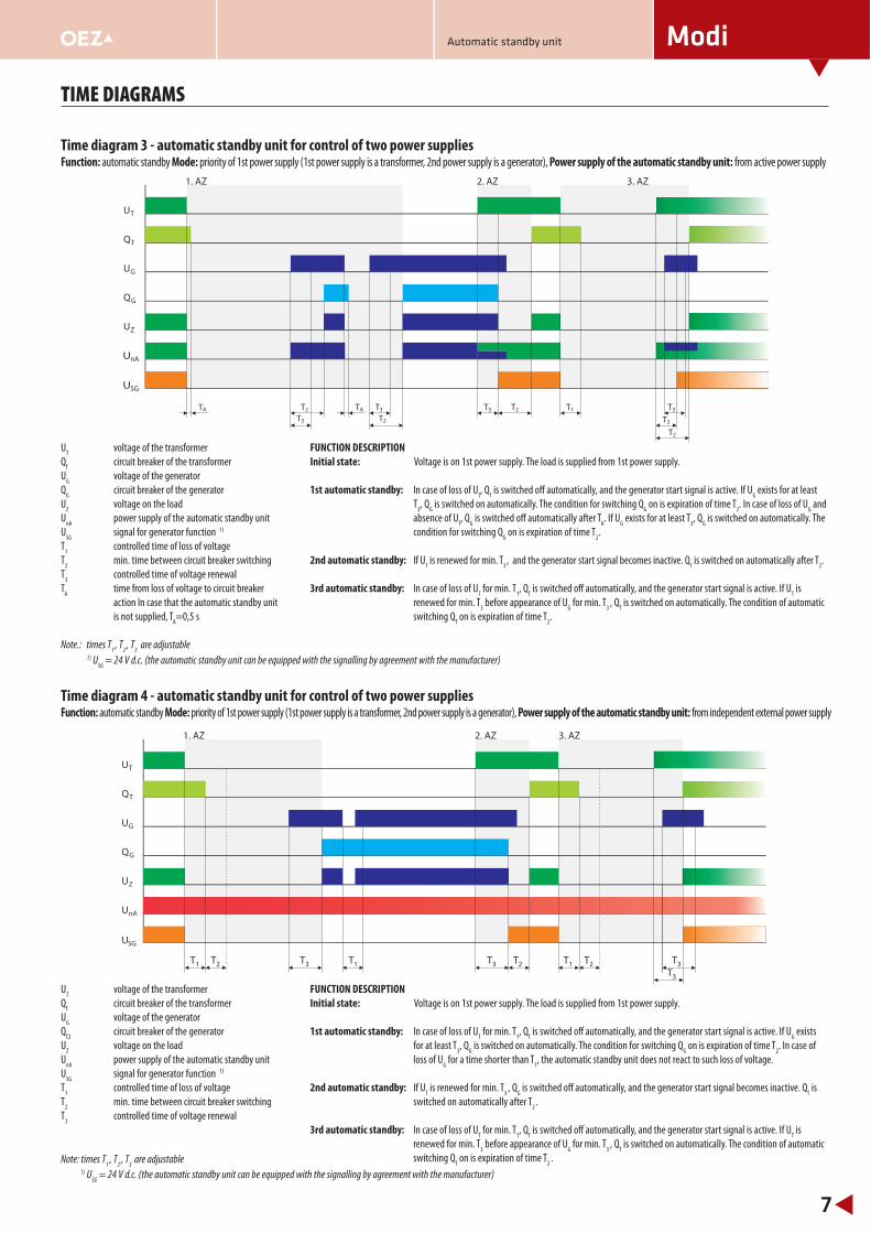
UT
voltage of the transformer
QT circuit breaker of the transformer
UG voltage of the generator
QG circuit breaker of the generator
UZ voltage on the load
UnA
power supply of the automatic standby unit
USG
signal for generator function 1)
T1 controlled time of loss of voltage
T2 min. time between circuit breaker switching
T3 controlled time of voltage renewal
TA
time from loss of voltage to circuit breaker
action In case that the automatic standby unit
is not supplied, TA=0,5 s
Note.: times T1
, T2
, T3 are adjustable
FUNCTION DESCRIPTION
Initial state: Voltage is on 1st power supply. The load is supplied from 1st power supply.
1st automatic standby: In case of loss of UT, Q
T is switched off automatically, and the generator start signal is active. If U
G exists for at least
T3, Q
G is switched on automatically. The condition for switching Q
G on is expiration of time T
2. In case of loss of U
G and
absence of UT, Q
G is switched off automatically after T
A. If U
G exists for at least T
3, Q
G is switched on automatically. The
condition for switching QG on is expiration of time T
2.
2nd automatic standby: If UT is renewed for min. T
3 , and the generator start signal becomes inactive. Q
T is switched on automatically after T
2.
3rd automatic standby: In case of loss of UT for min. T
1, Q
T is switched off automatically, and the generator start signal is active. If U
T is
renewed for min. T3 before appearance of U
G for min. T
3 , Q
T is switched on automatically. The condition of automatic
switching QT on is expiration of time T
2.
Time diagram 3 - automatic standby unit for control of two power suppliesFunction: automatic standby Mode: priority of 1st power supply (1st power supply is a transformer, 2nd power supply is a generator), Power supply of the automatic standby unit: from active power supply
Time diagram 4 - automatic standby unit for control of two power suppliesFunction: automatic standby Mode: priority of 1st power supply (1st power supply is a transformer, 2nd power supply is a generator), Power supply of the automatic standby unit: from independent external power supply
UT
voltage of the transformer
QT circuit breaker of the transformer
UG voltage of the generator
QT2
circuit breaker of the generator
UZ voltage on the load
UnA
power supply of the automatic standby unit
USG
signal for generator function 1)
T1 controlled time of loss of voltage
T2 min. time between circuit breaker switching
T3 controlled time of voltage renewal
Note: times T1
, T2
, T3
are adjustable
FUNCTION DESCRIPTION
Initial state: Voltage is on 1st power supply. The load is supplied from 1st power supply.
1st automatic standby: In case of loss of UT for min. T
1, Q
T is switched off automatically, and the generator start signal is active. If U
G exists
for at least T3, Q
G is switched on automatically. The condition for switching Q
G on is expiration of time T
2. In case of
loss of UG for a time shorter than T
1, the automatic standby unit does not react to such loss of voltage.
2nd automatic standby: If UT is renewed for min. T
3 , Q
G is switched off automatically, and the generator start signal becomes inactive. Q
T is
switched on automatically after T2
.
3rd automatic standby: In case of loss of UT for min. T
1, Q
T is switched off automatically, and the generator start signal is active. If U
T is
renewed for min. T3 before appearance of U
G for min. T
3 , Q
T is switched on automatically. The condition of automatic
switching QT on is expiration of time T
2 .
1. AZ 2. AZ 3. AZ
UT
QT
UG
SG
QG
UZ
U
U
T2 T2
T2
T1T3T3 T3
T3
TATA
T3 T2
nA
1. AZ 2. AZ 3. AZ
UT
QT
UG
QG
SG
UZ
U
U
T1 T1T1T2 T2 T2T3 T3 T3T3
nA
1) USG
= 24 V d.c. (the automatic standby unit can be equipped with the signalling by agreement with the manufacturer)
1) USG
= 24 V d.c. (the automatic standby unit can be equipped with the signalling by agreement with the manufacturer)
Automatic standby unit
Modi
8
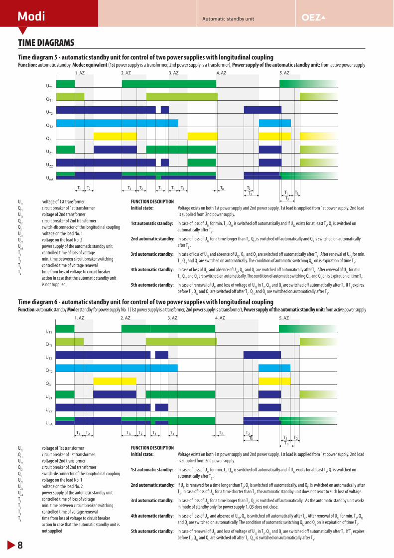
TIME DIAGRAMSTime diagram 5 - automatic standby unit for control of two power supplies with longitudinal couplingFunction: automatic standby Mode: equivalent (1st power supply is a transformer, 2nd power supply is a transformer), Power supply of the automatic standby unit: from active power supply
UT1
voltage of 1st transformer
QT1
circuit breaker of 1st transformer
UT2
voltage of 2nd transformer
QT2
circuit breaker of 2nd transformer
Q3 switch-disconnector of the longitudinal coupling
UZ1
voltage on the load No. 1
UZ2
voltage on the load No. 2
UnA
power supply of the automatic standby unit
T1 controlled time of loss of voltage
T2 min. time between circuit breaker switching
T3 controlled time of voltage renewal
TA
time from loss of voltage to circuit breaker
action In case that the automatic standby unit
is not supplied
FUNCTION DESCRIPTION
Initial state: Voltage exists on both 1st power supply and 2nd power supply. 1st load is supplied from 1st power supply. 2nd load
is supplied from 2nd power supply.
1st automatic standby: In case of loss of UT1
for min. T1, Q
T1 is switched off automatically and if U
T2 exists for at least T
3, Q
3 is switched on
automatically after T2.
2nd automatic standby: In case of loss of UT2
for a time longer than T1, Q
T2 is switched off automatically and Q
3 is switched on automatically
after T2 .
3rd automatic standby: In case of loss of UT1
and absence of UT2
, QT1
and Q3 are switched off automatically after T
A . After renewal of U
T2 for min.
T3, Q
T2 and Q
3 are switched on automatically. The condition of automatic switching Q
T2 on is expiration of time T
2.
4th automatic standby: In case of loss of UT1
and absence of UT2
, QT1
and Q3 are switched off automatically after T
A . After renewal of U
T2 for min.
T3, Q
T2 and Q
3 are switched on automatically. The condition of automatic switching Q
T2 and Q
3 on is expiration of time T
2.
5th automatic standby: In case of renewal of UT1
and loss of voltage of UT2
in T3, Q
T2 and Q
3 are switched off automatically after T
1. If T
3 expires
before T1, Q
T2 and Q
3 are switched off after T
3. Q
T1 and Q
3 are switched on automatically after T
2.
1. AZ 2. AZ 5. AZ3. AZ 4. AZ
UT2
QT2
Q3
UZ1
UZ2
UnA
QT1
UT1
T1 T2 T3 T1 T2 TAT1
T3
T3
T2T2T1
T2
Time diagram 6 - automatic standby unit for control of two power supplies with longitudinal couplingFunction: automatic standby Mode: standby for power supply No. 1 (1st power supply is a transformer, 2nd power supply is a transformer), Power supply of the automatic standby unit: from active power supply
FUNCTION DESCRIPTION
Initial state: Voltage exists on both 1st power supply and 2nd power supply. 1st load is supplied from 1st power supply. 2nd load
is supplied from 2nd power supply.
1st automatic standby: In case of loss of UT1
for min. T1, Q
T1 is switched off automatically and if U
T2 exists for at least T
3, Q
3 is switched on
automatically after T2
.
2nd automatic standby: If UT1
is renewed for a time longer than T3, Q
3 is switched off automatically, and Q
T1 is switched on automatically after
T2. In case of loss of U
T2 for a time shorter than T
1, the automatic standby unit does not react to such loss of voltage.
3rd automatic standby: In case of loss of UT2
for a time longer than T1, Q
T2 is switched off automatically. As the automatic standby unit works
in mode of standby only for power supply 1, Q3 does not close.
4th automatic standby: In case of loss of UT1
and absence of UT2
, QT1
is switched off automatically after TA
. After renewal of UT2
for min. T3, Q
T2
and Q3 are switched on automatically. The condition of automatic switching Q
T2 and Q
3 on is expiration of time T
2.
5th automatic standby: In case of renewal of UT1
and loss of voltage of UT2
in T3, Q
T2 and Q
3 are switched off automatically after T
1. If T
3 expires
before T1, Q
T2 and Q
3 are switched off after T
3. Q
T1 is switched on automatically after T
2.
1. AZ 2. AZ 4. AZ 5. AZ3. AZ
UT2
QT2
Q3
UZ1
UZ2
UnA
QT1
UT1
T1 T2 T1 TAT1
T3
T3
T2T2T1
T3 T2
UT1
voltage of 1st transformer
QT1
circuit breaker of 1st transformer
UT2
voltage of 2nd transformer
QT2
circuit breaker of 2nd transformer
Q3 switch-disconnector of the longitudinal coupling
UZ1
voltage on the load No. 1
UZ2
voltage on the load No. 2
UnA
power supply of the automatic standby unit
T1 controlled time of loss of voltage
T2 min. time between circuit breaker switching
T3 controlled time of voltage renewal
TA
time from loss of voltage to circuit breaker
action In case that the automatic standby unit is
not supplied
Automatic standby unit
Modi
9
TIME DIAGRAMS
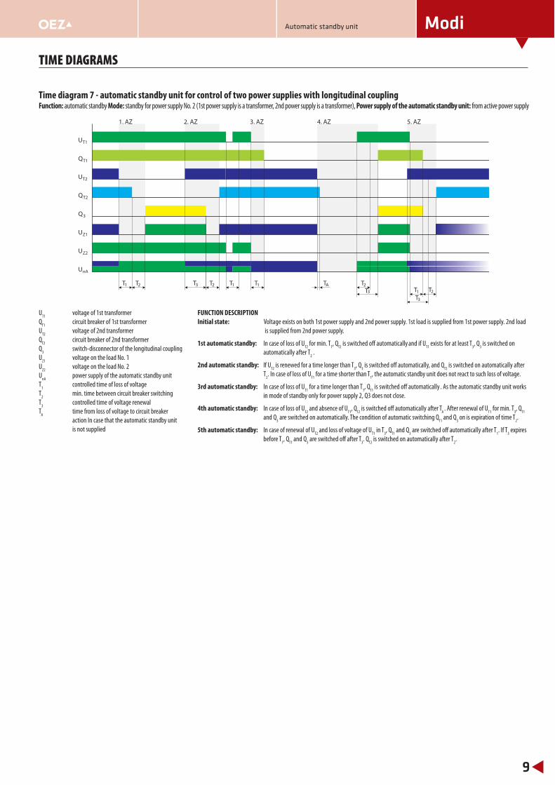
Time diagram 7 - automatic standby unit for control of two power supplies with longitudinal coupling Function: automatic standby Mode: standby for power supply No. 2 (1st power supply is a transformer, 2nd power supply is a transformer), Power supply of the automatic standby unit: from active power supply
1. AZ 2. AZ 4. AZ 5. AZ3. AZ
UT2
QT2
Q3
UZ1
UZ2
UnA
QT1
UT1
T1 T2 T1 TAT1
T3
T3
T2T2T1
T3 T2
UT1
voltage of 1st transformer
QT1
circuit breaker of 1st transformer
UT2
voltage of 2nd transformer
QT2
circuit breaker of 2nd transformer
Q3 switch-disconnector of the longitudinal coupling
UZ1
voltage on the load No. 1
UZ2
voltage on the load No. 2
UnA
power supply of the automatic standby unit
T1 controlled time of loss of voltage
T2 min. time between circuit breaker switching
T3 controlled time of voltage renewal
TA
time from loss of voltage to circuit breaker
action In case that the automatic standby unit
is not supplied
FUNCTION DESCRIPTION
Initial state: Voltage exists on both 1st power supply and 2nd power supply. 1st load is supplied from 1st power supply. 2nd load
is supplied from 2nd power supply.
1st automatic standby: In case of loss of UT2
for min. T1, Q
T2 is switched off automatically and if U
T1 exists for at least T
3, Q
3 is switched on
automatically after T2 .
2nd automatic standby: If UT2
is renewed for a time longer than T3, Q
3 is switched off automatically, and Q
T2 is switched on automatically after
T2. In case of loss of U
T1 for a time shorter than T
1, the automatic standby unit does not react to such loss of voltage.
3rd automatic standby: In case of loss of UT1
for a time longer than T1, Q
T1 is switched off automatically . As the automatic standby unit works
in mode of standby only for power supply 2, Q3 does not close.
4th automatic standby: In case of loss of UT2
and absence of UT1
, QT2
is switched off automatically after TA
. After renewal of UT1
for min. T3, Q
T1
and Q3 are switched on automatically. The condition of automatic switching Q
T1 and Q
3 on is expiration of time T
2.
5th automatic standby: In case of renewal of UT2
and loss of voltage of UT1
in T3, Q
T1 and Q
3 are switched off automatically after T
1. If T
3 expires
before T1, Q
T1 and Q
3 are switched off after T
3. Q
T2 is switched on automatically after T
2.
Automatic standby unit

Modi
10
SPECIFICATIONS
AUTOMATIC STANDBY UNIT MODI
Dimensions W x H x D ZA-x0-xxxx 500 x 500 x 150 mm
ZA-x1-xxxx see page 21
Weight m ZA-00-xxxx or ZA-10-xxxx 21 kg
ZA-01-xxxx or ZA-11-xxxx 11 kg
Standards EN 947-6-1; EN 60204-1; EN 60068-2-1; EN 60068-2-2; EN 60068-3-3
POWER SUPPLY Ik“ = max. 10 kA, I
k“ ≥ 10 kA - necessary protection by fuses 6 ÷ 16 A with characteristic gG
External (outlets 26, 27) from independent power supply
Rated operating voltage AC Ue
24 V1) for ZA-xx-x0(1)xx, or 110 ÷ 230 V for ZA-xx-x2xx
DC Ue
24 V1) for ZA-xx-x0(1)xx, or 110 ÷ 230 V for ZA-xx-x2xx
Input power AC/DC 100 VA / 100 W
Overvoltage category I 5)
Internal 2) from active power supply
Rated frequency fn
50/60 Hz
Degree of protection internal/external ZA-x0-xxxx IP65
ZA-x1-xxxx IP65/20
Electromagnetic compatibility standards EN 60947-1; EN 55011
radio emission ZA-00-xxxx or ZA-10-xxxx class B
ZA-01-xxxx or ZA-11-xxxx class A
disturbing voltages ZA-00-xxxx or ZA-10-xxxx class B
ZA-01-xxxx or ZA-11-xxxx class B
Connecting cross-section 0.5 ÷ 1 mm2 (recommended section min. 0.75 mm2)
Range of ambient temperature 0 ÷ 50 °C
OPERATION SIGNALLING (the signalling only functions if the automatic standby unit is supplied)
Local: LCD
Remote: (outlets 12-18) AC Ie /U
e 10 A/230 V (AC-3) (potential-less contacts)
(outlets 22-25) DC Ie /U
e 0.1 A/24 V (against terminal -)
Connecting cross-section 0.5 ÷ 1 mm2 (recommended section min. 0.75 mm2)
UNDERVOLTAGE RELAY
Undervoltage setting max. - 30 % Un
Overvoltage setting max. + 30 % Un
TIME SETTING
Controlled time of loss of voltage 3) T1 0 ÷ 999 s, by 1 s
Min. time between circuit breaker switching 3) T2 0 ÷ 999 s, by 1 s
Controlled time of voltage renewal T3 0 ÷ 999 s, by 1 s
Time from loss of voltage to circuit breaker action 4) TA
0.5 s
Note: Ik“ – short-circuit current in the circuit of power supplies
1) depending on design, see page 42) from the power supply which is connected to the load; in failure of both power supplies the automatic standby unit is without voltage until voltage is renewed on one of the power supplies3) in case of permanent supplying of the automatic standby unit4) in case that the automatic standby unit is not supplied5) with regard to classifi cation of the device in the overvoltage category I (sensitive electronic devices) according to EN 60664-1 it is recommended to protect the automatic standby unit Modi
against overvoltage in accordance with EN 62305. For selection of an appropriate overvoltage protection it is possible to refer to the Overvoltage protections application manual, which can
be freely downloaded at www.oez.com..
EQUIPMENT OF CIRCUIT BREAKERS
Note: For detailed information on circuit breakers/switch-disconnectors BC160, BD250, BH630 and BL… see the catalogue Moulded case circuit breakers J1-2011-A
For detailed information on circuit breakers/switch-disconnectors ARION WL see the catalogue Air circuit breakers VJ1-2007-A
Circuit breaker type BC160 BD250 BH630 BL… ARION WL
Accessories
Undervoltage release SP-BC-X024 SP-BHD-X024 SP-BHD-X024 SP-BL-X024 see page 11
Auxiliary switch PS-BC-0010-Au PS-BHD-1100-Au PS-BHD-1100-Au PS-BL-2200-Au see page 11
Signal switch NS-BC-0010-Au PS-BHD-1000-Au PS-BHD-1000-Au - see page 11
Relative switch - - - PS-BL-2200-Au see page 11
Motor drive MP-BC-X230-B MP-BD-X230 MP-BH-X230 MP-BL-X230 see page 11
Mechanical interlocking - see page 11 see page 11 see page 11 see page 11
Automatic standby unit

Modi
11
TYPE DESIGNATION OF CIRCUIT BREAKER ARION WL
Circuit breaker equipment must include these accessories:
�� Motor drive – 230 V a.c.
�� Undervoltage release – 24 V d.c.
�� Auxiliary contacts – 2NO + 2NC
�� Signal switch „Ready-to-close” (S20)
�� Signal switch „Switched off by release“ (S24)
�� Mechanical interlocking
Type designation:
Arion WL . . . . - . . . . . – 4 A J 2 – Z C 2 2 + K 0 7 + x x x
Type designation description:
Arion WL . . . . – . . . . . – 4 A J 2 – Z C 2 2 + K 0 7 + x x x
Mechanical interlocking 1)
Signal switch „Switched off by release“ (S24)
Signal switch „Ready-to-close“ (S20)
Motor drive and closing release - 230 V a.c.
Without 1st auxiliary release
Undervoltage release - 24 V d.c.
One block of auxiliary switches - 2NO+2NC
VBreaking capacity, electronic overcurrent release, number of poles and design 2)
Circuit breaker size, rated current 2)
1) x x x – Mechanical interlocking according to circuit breaker design:
S55 – Fixed design
R55 – Withdrawable design of circuit breaker
2) see the catalogue Air circuit breakers VJ1-2007-A
DETERMINATION OF MECHANICAL INTERLOCKING OF CIRCUIT BREAKERS MODEION
Circuit breaker combination Mechanical interlocking according to circuit breakers designs
1st circuit breaker 2nd circuit breaker Fixed Plug-in Withdrawable Fixed/withdrawable (plug-in)
BC160 BC160 - - - -
BD250 BD250 MB-BD-PV05 MB-BD-PV05 MB-BD-PV05 MB-BD-PV05
BD250 BH630 MB-BHD-PV03 MB-BHD-PV03 MB-BHD-PV03 MB-BHD-PV03
BH630 BH630 MB-BH-PV04 MB-BH-PV04 MB-BH-PV04 MB-BH-PV04
BH630 BD250 MB-BHD-PV03 MB-BHD-PV03 MB-BHD-PV03 MB-BHD-PV03
BL… BL… MB-BL-PP07 - MB-BL-VV06 MB-BL-PV08
Automatic standby unit
Modi
12
WIRING DIAGRAM / DIAGRAM
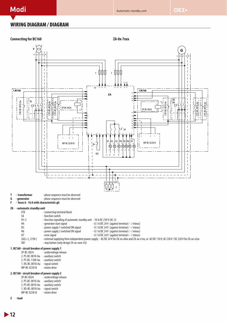
Connecting for BC160 ZA-0x-7xxx
1L1 1L2 2L2 2L3
104
105
107
103
4
5
7
3
13 14 15
1L3 2L1
12
34
56
3.4
3.1
A1A2
12
34
56
A1A2
PE N
X1X2
X1X2
X1X2
2.2
2.1
1
101
-
6
106
26
12 22 2423
X1X2
X1X2
X1X2
25X1
X2
8
9
2
109
108
102
11
111
10 110
27
1.2
1.1
1.2
1.1
3.4
3.1
2.2
2.1
30 31
12
GL1L2L3
N PE
L1 L2 L3
L1 L2 L3
N- N- N-
4 141 2
N PEN PE
L+
L+
XT0
2
N-
ZA
BC
3.PS-BC-0010-Au
SP-BC-X024
BH
SP-BC-X024
H1 H2 H3
T
2.PS-BC-0010-Au
SA
Z
F F
1.BC160
MP-BC-X230-B
BD
H4 H5 H6 H7
1.NS-BC-0010-Au
1.NS-BC-0010-Au
3.PS-BC-0010-Au
2.PS-BC-0010-Au
MP-BC-X230-B
1.BC160
-SB1
T - transformer - phase sequence must be observedG - generator - phase sequence must be observedF - fuses 6 - 16 A with characteristic gG
ZA - automatic standby unit XT0 - connecting terminal block SA - function switch H1-3 - function signalling of automatic standby unit - 10 A/AC 230 V (AC-3) H4 - generator start signal - 0.1 A/DC 24 V (against terminal / - / minus) H5 - power supply 1 switched ON signal - 0.1 A/DC 24 V (against terminal / - / minus) H6 - power supply 2 switched ON signal - 0.1 A/DC 24 V (against terminal / - / minus) H7 - error signal - 0.1 A/DC 24 V (against terminal / - / minus) 26(L+), 27(N-) - external supplying from independent power supply - AC/DC 24 V for ZA-xx-x0xx and ZA-xx-x1xx, or AC/DC 110 V, AC 230 V / DC 220 V for ZA-xx-x2xx SB1 - stop button (only design ZA-xx-xxxx-A3)
1. BC160 - circuit breaker of power supply 1 SP-BC-X024 - undervoltage release 2. PS-BC-0010-Au - auxiliary switch 3. PS-BC-1100-Au - auxiliary switch 1. NS-BC-0010-Au - signal switch MP-BC-X230-B - motor drive
2. BC160 - circuit breaker of power supply 2 SP-BC-X024 - undervoltage release 2. PS-BC-0010-Au - auxiliary switch 3. PS-BC-0010-Au - auxiliary switch 1. NS-BC-0010-Au - signal switch MP-BC-X230-B - motor drive
Z - load
Automatic standby unit
Modi
13
WIRING DIAGRAM / DIAGRAM
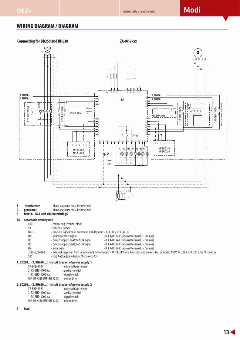
Connecting for BD250 and BH630 ZA-0x-7xxx
1L1 1L2 2L2 2L3
104
105
107
103
4
5
7
3
13 14 15
1L3 2L1
12
34
56
3.3
3.4
A1A2
12
34
56
3.3
3.4
A1A2
PE N
X1X2
X1X2
X1X2
2.1
2.2
2.1
2.2
1
101
1.3
1.4
1.3
1.4
-
6
106
26
12 22 2423
X1X2
X1X2
X1X2
25
X1X2
8
9
2
109
108
102
11
111
10 110
27
30 31
12
GL1L2L3
N PE
L1 L2 L3
L1 L2 L3
N- N- N-
4 15641 5 2 6
N PEN PE
L+
L+
XT0
2
N-
ZA
BH
3.PS-B
HD-1100Au
SP-BHD-X024
BH
3.PS-B
HD-1100Au
SP-BHD-X024
H1 H2 H3
1.BH630... 2.BH630...
T
MP-BH-X230MP-BH-X230
1.PS-B
HD-1000Au
1.PS-B
HD-1000Au
SA
Z
F F
1.BD250...
BD
MP-BD-X230
2.BD250...
BD
MP-BD-X230H4 H5 H6 H7
-SB1
T - transformer - phase sequence must be observedG - generator - phase sequence must be observedF - fuses 6 - 16 A with characteristic gG
ZA - automatic standby unit XT0 - connecting terminal block SA - function switch H1-3 - function signalling of automatic standby unit - 10 A/AC 230 V (AC-3) H4 - generator start signal - 0.1 A/DC 24 V (against terminal / - / minus) H5 - power supply 1 switched ON signal - 0.1 A/DC 24 V (against terminal / - / minus) H6 - power supply 2 switched ON signal - 0.1 A/DC 24 V (against terminal / - / minus) H7 - error signal - 0.1 A/DC 24 V (against terminal / - / minus) 26(L+), 27(N-) - external supplying from independent power supply - AC/DC 24 V for ZA-xx-x0xx and ZA-xx-x1xx, or AC/DC 110 V, AC 230 V / DC 220 V for ZA-xx-x2xx SB1 - stop button (only design ZA-xx-xxxx-A3)
1. BD250…(1. BH630…) - circuit breaker of power supply 1 SP-BHD-X024 - undervoltage release 3. PS-BHD-1100-Au - auxiliary switch 1. PS-BHD-1000-Au - signal switch MP-BD-X230 (MP-BH-X230) - motor drive
2. BD250…(2. BH630…) - circuit breaker of power supply 2 SP-BHD-X024 - undervoltage release 3. PS-BHD-1100-Au - auxiliary switch 1. PS-BHD-1000-Au - signal switch MP-BD-X230 (MP-BH-X230) - motor drive Z - load
Automatic standby unit

Modi
14
WIRING DIAGRAM / DIAGRAM
Connecting for BL1600/BL1000 ZA-0x-8xxx
1L1 1L2 2L2 2L3
104
105
107
103
4
5
7
3
1L3 2L1
12
34
56
1.13
1.14
A1A2
12
34
56
1.13
1.14A1
A2
PE N
1.21
1.22
1.21
1.22
1
101
3.13
3.14
3.13
3.14
-
6
106
26
12
3.21
3.22
3.21
3.22
13 14 15
X1X2
X1X2
X1X2
22 2423
X1X2
X1X2
X1X2
25X1
X2
2
9
8
102
109
108
11111
27
30 31
12
GL1L2L3
N PE
L1 L2 L3
L1 L2 L3
4 1241 2
N PEN PE
L+
L+
9
10
9
10
N-N-N-
XT0
N-
ZABL
1.PS
-BL-
2200
Au
SP-BL-X024
BL
1.PS
-BL-
2200
Au
SP-BL-X024
1.BL1000... 2.BL1000...
T
MP-BL-X...MP-BL-X...
3.PS
-BL-
2200
Au
3.PS
-BL-
2200
Au
Z
F F
1.BL1600... 2.BL1600...
H1 H2 H3
SA
H4 H5 H6 H7
-SB1
T - transformer - phase sequence must be observedG - generator - phase sequence must be observedF - fuses 6 - 16 A with characteristic gG
ZA - automatic standby unit XT0 - connecting terminal block SA - function switch H1-3 - function signalling of automatic standby unit - 10 A/AC 230 V (AC-3) H4 - generator start signal - 0.1 A/DC 24 V (against terminal / - / minus) H5 - power supply 1 switched ON signal - 0.1 A/DC 24 V (against terminal / - / minus) H6 - power supply 2 switched ON signal - 0.1 A/DC 24 V (against terminal / - / minus) H7 - error signal - 0.1 A/DC 24 V (against terminal / - / minus) 26(L+), 27(N-) - external supplying from independent power supply - AC/DC 24 V for ZA-xx-x0xx and ZA-xx-x1xx, or AC/DC 110 V, AC 230 V / DC 220 V for ZA-xx-x2xx SB1 - stop button (only design ZA-xx-xxxx-A3)
1. BL... - circuit breaker of power supply 1 SP-BL-X024 - undervoltage release 3. PS-BL-2200-Au - auxiliary switch 1. PS-BL-2200-Au - signal switch MP-BL-X230 - motor drive
2. BL... - circuit breaker of power supply 2 SP-BL-X024 - undervoltage release 3. PS-BL-2200-Au - auxiliary switch 1. PS-BL-2200-Au - signal switch MP-BL-X230 - motor drive
Z - load
Automatic standby unit
Modi
15
WIRING DIAGRAM / DIAGRAM
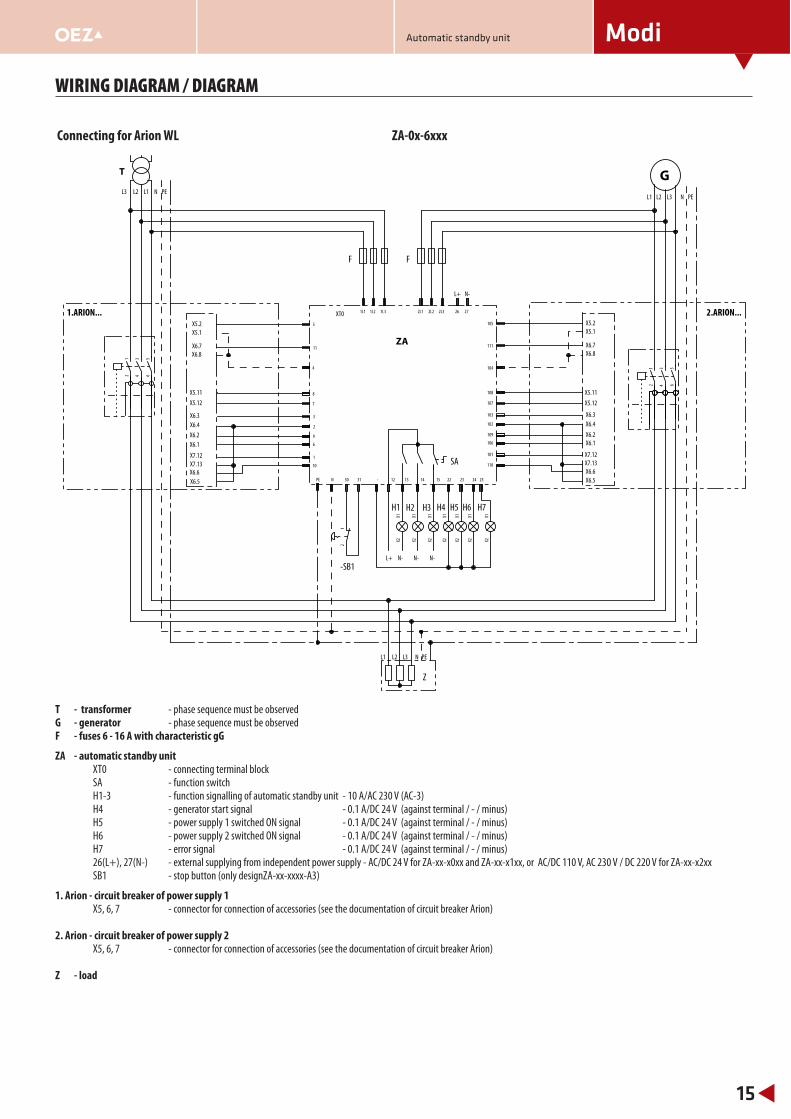
Connecting for Arion WL ZA-0x-6xxx
1L1 1L2 2L2 2L3
105
111
107
103
5
11
7
3
1L3 2L1
12
34
56
12
34
56
PE N
1101
-
6 106
26
12
10 110
13 14 15
X1X2
X1X2
X1X2
22 2423
X1X2
X1X2
X1X2
25
X1X2
8
2
9
108
102
109
4 104
27
30 31
12
GL1L2L3
N PE
L1 L2 L3
L1 L2 L3
N PEN PE
L+
L+
X5.2
X5.1
X6.7
X6.8
X6.2
X5.12
X6.3
X6.4
X6.1
X5.11
X7.12
X7.13
X6.6
X5.2
X5.1
X6.7
X6.8
X6.3
X6.4
X6.1
X6.2
X7.12
X7.13
X6.6
X5.11
X5.12
N- N- N-
XT0
N-
X6.5 X6.5
ZA
1.ARION... 2.ARION...
T
Z
F F
H1 H2 H3
SA
H4 H5 H6 H7
-SB1
T - transformer - phase sequence must be observedG - generator - phase sequence must be observedF - fuses 6 - 16 A with characteristic gG
ZA - automatic standby unit XT0 - connecting terminal block SA - function switch H1-3 - function signalling of automatic standby unit - 10 A/AC 230 V (AC-3) H4 - generator start signal - 0.1 A/DC 24 V (against terminal / - / minus) H5 - power supply 1 switched ON signal - 0.1 A/DC 24 V (against terminal / - / minus) H6 - power supply 2 switched ON signal - 0.1 A/DC 24 V (against terminal / - / minus) H7 - error signal - 0.1 A/DC 24 V (against terminal / - / minus) 26(L+), 27(N-) - external supplying from independent power supply - AC/DC 24 V for ZA-xx-x0xx and ZA-xx-x1xx, or AC/DC 110 V, AC 230 V / DC 220 V for ZA-xx-x2xx SB1 - stop button (only designZA-xx-xxxx-A3)
1. Arion - circuit breaker of power supply 1 X5, 6, 7 - connector for connection of accessories (see the documentation of circuit breaker Arion) 2. Arion - circuit breaker of power supply 2 X5, 6, 7 - connector for connection of accessories (see the documentation of circuit breaker Arion) Z - load
Automatic standby unit
Modi
16
WIRING DIAGRAM / DIAGRAM
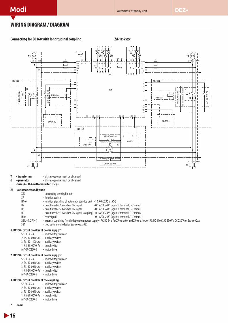
Connecting for BC160 with longitudinal coupling ZA-1x-7xxx
12
34
56
3.4
3.1
A1A2
12
34
56
3.4
3.1
A1A2
12
34
56
3.13.4A1A2
1.2
1.1
1.2
1.1
1.21.1
12
L1L2L3
N PE
L1 L2 L3
L1 L2 L3
4 141 2
N PE N PE
XT0
2
N PEL1 L2 L3
2 4 1
..................
- - - - -
- -
2
5
8
4
7
6
3
1
107
106
104
108
105
102
101
103
205208204202201 203207 206
1L1
1L2
1L3
N
PE
2L1
2L2
2L3
N
PE
26 27
N-L+
-
-
22 23 24 2512
L+
13 14 15 16 17 18
H7 H8 H9 H10
Uz
N- N- N- N- N- N-
H1 H2 H3 H4 H5 H6
Uv
+ + + +
30 31
ZA
3.PS-BC-0010-Au
SP-BC-X024
3.PS-BC-0010-Au
SP-BC-X024
T1
Z2
F F
1.BC 160
BC
MP-BC-X...
2.BC 160
BC
MP-BC-X...
T2
Z1
SP-BC-X024
3.PS-BC-0010-Au
1.NS-BC-0010-Au
MP-BC-X...
SA1
1.NS-BC-0010-Au
1.NS-BC-0010-Au
3.BC 160
BC
-SB1
T - transformer - phase sequence must be observedG - generator - phase sequence must be observedF - fuses 6 - 16 A with characteristic gG
ZA - automatic standby unit XT0 - connecting terminal block SA - function switch H1-6 - function signalling of automatic standby unit - 10 A/AC 230 V (AC-3) H7 - circuit breaker 1 switched ON signal - 0.1 A/DC 24 V (against terminal / - / minus) H8 - circuit breaker 2 switched ON signal - 0.1 A/DC 24 V (against terminal / - / minus) H9 - circuit breaker 3 switched ON signal (coupling) - 0.1 A/DC 24 V (against terminal / - / minus) H10 - error signal - 0.1 A/DC 24 V (against terminal / - / minus) 26(L+), 27(N-) - external supplying from independent power supply - AC/DC 24 V for ZA-xx-x0xx and ZA-xx-x1xx, or AC/DC 110 V, AC 230 V / DC 220 V for ZA-xx-x2xx SB1 - stop button (only design ZA-xx-xxxx-A3)
1. BC160 - circuit breaker of power supply 1 SP-BC-X024 - undervoltage release 2. PS-BC-0010-Au - auxiliary switch 3. PS-BC-1100-Au - auxiliary switch 1. NS-BC-0010-Au - signal switch MP-BC-X230-B - motor drive
2. BC160 - circuit breaker of power supply 2 SP-BC-X024 - undervoltage release 2. PS-BC-0010-Au - auxiliary switch 3. PS-BC-0010-Au - auxiliary switch 1. NS-BC-0010-Au - signal switch MP-BC-X230-B - motor drive
3. BC160 - circuit breaker of the coupling SP-BC-X024 - undervoltage release 2. PS-BC-0010-Au - auxiliary switch 3. PS-BC-0010-Au - auxiliary switch 1. NS-BC-0010-Au - signal switch MP-BC-X230-B - motor drive
Z - load
Automatic standby unit
Modi
17
WIRING DIAGRAM / DIAGRAM
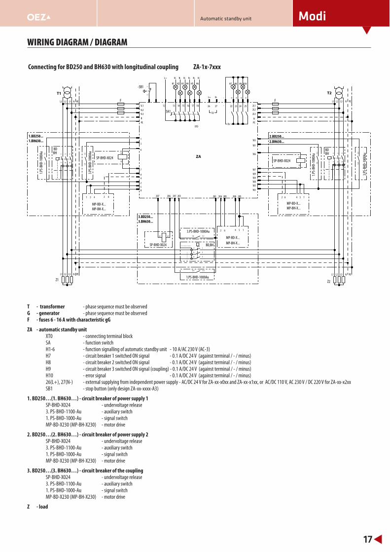
Connecting for BD250 and BH630 with longitudinal coupling ZA-1x-7xxx1
2
34
56
3.3
3.4
A1A2
12
34
56
3.3
3.4
A1A2
1.3
1.4
1.3
1.4
12
34
56
1.31.4
3.33.4
A1A2
12
L1L2L3
N PE
L1 L2 L3
L1 L2 L3
4 15641 5 2 6
N PE N PE
XT0
2
N PEL1 L2 L3
2 6 4 5 1
..................
- - - - -
- -
2
5
8
4
9
7
6
3
1
107
106
109
104
108
105
102
101
103
205208209204202201 203207 206
1L1
1L2
1L3
N
PE
2L1
2L2
2L3
N
PE
26 27
N-L+
-
-
22 23 24 2512
L+
13 14 15 16 17 18
H7 H8 H9 H10
Uz
N- N- N- N- N- N-
H1 H2 H3 H4 H5 H6
Uv
+ + + +
ZABH
3.PS-B
HD-1000Au
SP-BHD-X024BH
3.PS-B
HD-1000Au
SP-BHD-X024
1.BH630... 2.BH630...
T1
MP-BH-X...MP-BH-X...
1.PS-B
HD-1000Au
1.PS-B
HD-1000Au
Z2
F F
1.BD250...
BD
MP-BD-X...
2.BD250...
BD
MP-BD-X...
T2
Z1
SP-BHD-X024
3.PS-BHD-1000Au
1.PS-BHD-1000Au
BD,BH
MP-BD-X...
MP-BH-X...
3.BD250...
3.BH630...
SA1
-SB1
T - transformer - phase sequence must be observedG - generator - phase sequence must be observedF - fuses 6 - 16 A with characteristic gG
ZA - automatic standby unit XT0 - connecting terminal block SA - function switch H1-6 - function signalling of automatic standby unit - 10 A/AC 230 V (AC-3) H7 - circuit breaker 1 switched ON signal - 0.1 A/DC 24 V (against terminal / - / minus) H8 - circuit breaker 2 switched ON signal - 0.1 A/DC 24 V (against terminal / - / minus) H9 - circuit breaker 3 switched ON signal (coupling) - 0.1 A/DC 24 V (against terminal / - / minus) H10 - error signal - 0.1 A/DC 24 V (against terminal / - / minus) 26(L+), 27(N-) - external supplying from independent power supply - AC/DC 24 V for ZA-xx-x0xx and ZA-xx-x1xx, or AC/DC 110 V, AC 230 V / DC 220 V for ZA-xx-x2xx SB1 - stop button (only design ZA-xx-xxxx-A3)
1. BD250…(1. BH630…) - circuit breaker of power supply 1 SP-BHD-X024 - undervoltage release 3. PS-BHD-1100-Au - auxiliary switch 1. PS-BHD-1000-Au - signal switch MP-BD-X230 (MP-BH-X230) - motor drive
2. BD250…(2. BH630…) - circuit breaker of power supply 2 SP-BHD-X024 - undervoltage release 3. PS-BHD-1100-Au - auxiliary switch 1. PS-BHD-1000-Au - signal switch MP-BD-X230 (MP-BH-X230) - motor drive
3. BD250…(3. BH630…) - circuit breaker of the coupling SP-BHD-X024 - undervoltage release 3. PS-BHD-1100-Au - auxiliary switch 1. PS-BHD-1000-Au - signal switch MP-BD-X230 (MP-BH-X230) - motor drive
Z - load
Automatic standby unit
Modi
18
WIRING DIAGRAM / DIAGRAM
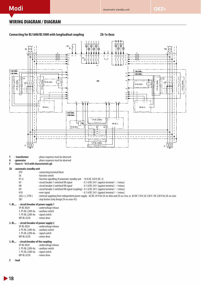
Connecting for BL1600/BL1000 with longitudinal coupling ZA-1x-8xxx
12
34
56
1.13
1.14
A1A2
12
34
56
1.13
1.14
A1A2
3.13
3.14
3.13
3.14
12
34
56
1.131.14
3.133.14
A1A2
3.21
3.22
3.213.22
3.21
3.22
12
L1L2L3
N PE
L1 L2 L3
L1 L2 L3
4 141 2
N PE N PE
XT0
2
N PEL1 L2 L3
2 4 1
..................
- - - - -
- -
2
5
8
4
7
6
3
1
107
106
104
108
105
102
101
103
205208204202201 203207 206
1L1
1L2
1L3
N
PE
2L1
2L2
2L3
N
PE
26 27
N-L+
-
-
22 23 24 2512
L+
13 14 15 16 17 18
H7 H8 H9 H10
Uz
N- N- N- N- N- N-
H1 H2 H3 H4 H5 H6
Uv
+ + + +
9
10
9 10
9
10
30 31
ZABL
1.PS-BL-2200Au
SP-BL-X024
BL
1.PS-BL-2200Au
SP-BL-X024
1.BL1000... 2.BL1000...
T1
3.PS-BL-2200Au
3.PS-BL-2200Au
Z2
F F
1.BL1600...
MP-BL-X...
2.BL1600...
MP-BL-X...
T2
Z1
SP-BL-X024
1.PS-BL-2200Au
3.PS-BL-2200Au
BL
MP-BL-X...
3.BL1600...
3.BH1000...
SA1
-SB1
T - transformer - phase sequence must be observedG - generator - phase sequence must be observedF - fuses 6 - 16 A with characteristic gG
ZA - automatic standby unit XT0 - connecting terminal block SA - function switch H1-6 - function signalling of automatic standby unit - 10 A/AC 230 V (AC-3) H7 - circuit breaker 1 switched ON signal - 0.1 A/DC 24 V (against terminal / - / minus) H8 - circuit breaker 2 switched ON signal - 0.1 A/DC 24 V (against terminal / - / minus) H9 - circuit breaker 3 switched ON signal (coupling) - 0.1 A/DC 24 V (against terminal / - / minus) H10 - error signal - 0.1 A/DC 24 V (against terminal / - / minus) 26(L+), 27(N-) - external supplying from independent power supply - AC/DC 24 V for ZA-xx-x0xx and ZA-xx-x1xx, or AC/DC 110 V, AC 230 V / DC 220 V for ZA-xx-x2xx SB1 - stop button (only design ZA-xx-xxxx-A3)
1. BL... - circuit breaker of power supply 1 SP-BL-X024 - undervoltage release 3. PS-BL-2200-Au - auxiliary switch 1. PS-BL-2200-Au - signal switch MP-BL-X230 - motor drive
2. BL... - circuit breaker of power supply 2 SP-BL-X024 - undervoltage release 3. PS-BL-2200-Au - auxiliary switch 1. PS-BL-2200-Au - signal switch MP-BL-X230 - motor drive
3. BL... - circuit breaker of the coupling SP-BL-X024 - undervoltage release 3. PS-BL-2200-Au - auxiliary switch 1. PS-BL-2200-Au - signal switch MP-BL-X230 - motor drive
Z - load
Automatic standby unit
Modi
19
WIRING DIAGRAM / DIAGRAM
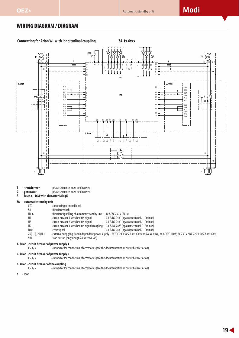
Connecting for Arion WL with longitudinal coupling ZA-1x-6xxx1
2
34
56
12
34
56
12
34
56
12
L1L2L3
N PE
L1 L2 L3
L1 L2 L3
N PE N PE
XT0
N PEL1 L2 L3
..................
- - - - -
- -
107
106
104
108
105
102
101
103
205 208 204 202 201203207 206
1L1
1L2
1L3
N
PE
2L1
2L2
2L3
N
PE
26 27
N-L+
-
-
22 23 24 2512
L+
13 14 15 16 17 18
H7 H8 H9 H10
Uz
N- N- N- N- N- N-
H1 H2 H3 H4 H5 H6
Uv
+ + + +
210
X5.2
X5.1
X6.7
X6.8
X5.11
X5.12
X6.3
X7.12
X6.5
X6.6
X6.4
X7.13
110
7
6
4
8
5
2
1
3
10
X5.2
X5.1
X6.7
X6.8
X5.11
X5.12
X6.3
X7.12
X6.5
X6.6
X6.4
X7.13
X5.2
X5.1
X6.7
X6.8
X5.12
X5.11
X6.3
X6.4
X7.13
X6.5
X7.12
X6.6
30 31
ZA
T1
Z2
F F
1.Arion 2.Arion
T2
Z1
3.Arion
SA1
-SB1
T - transformer - phase sequence must be observedG - generator - phase sequence must be observedF - fuses 6 - 16 A with characteristic gG
ZA - automatic standby unit XT0 - connecting terminal block SA - function switch H1-6 - function signalling of automatic standby unit - 10 A/AC 230 V (AC-3) H7 - circuit breaker 1 switched ON signal - 0.1 A/DC 24 V (against terminal / - / minus) H8 - circuit breaker 2 switched ON signal - 0.1 A/DC 24 V (against terminal / - / minus) H9 - circuit breaker 3 switched ON signal (coupling) - 0.1 A/DC 24 V (against terminal / - / minus) H10 - error signal - 0.1 A/DC 24 V (against terminal / - / minus) 26(L+), 27(N-) - external supplying from independent power supply - AC/DC 24 V for ZA-xx-x0xx and ZA-xx-x1xx, or AC/DC 110 V, AC 230 V / DC 220 V for ZA-xx-x2xx SB1 - stop button (only design ZA-xx-xxxx-A3)
1. Arion - circuit breaker of power supply 1 X5, 6, 7 - connector for connection of accessories (see the documentation of circuit breaker Arion)
2. Arion - circuit breaker of power supply 2 X5, 6, 7 - connector for connection of accessories (see the documentation of circuit breaker Arion)
3. Arion - circuit breaker of the coupling X5, 6, 7 - connector for connection of accessories (see the documentation of circuit breaker Arion)
Z - load
Automatic standby unit
Modi
20
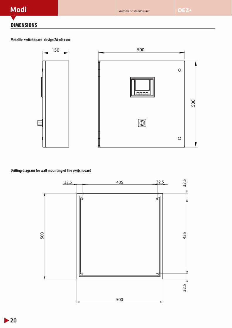
DIMENSIONS
Metallic switchboard design ZA-x0-xxxx
Drilling diagram for wall mounting of the switchboard
500
500150
435
500
500
32.543
532
.532
.532.5
Automatic standby unit
Modi
21
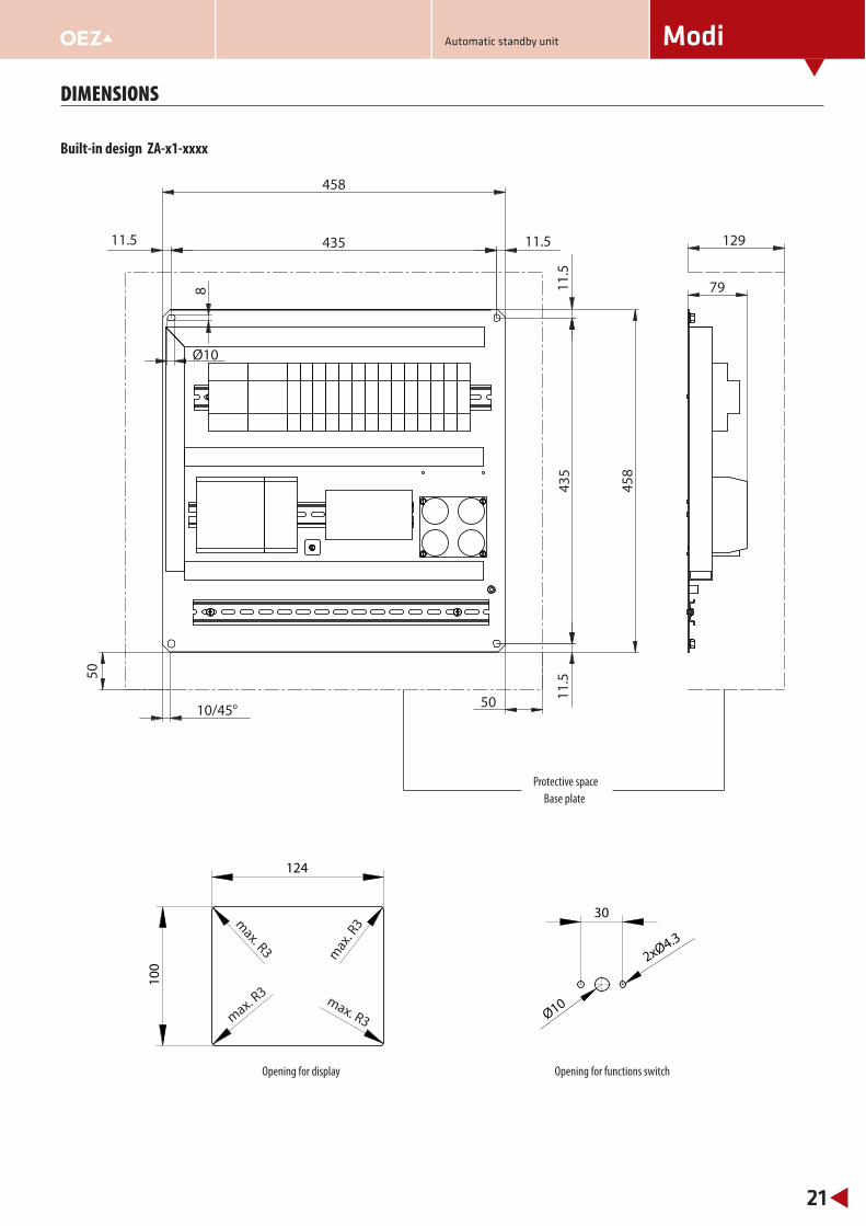
DIMENSIONS
Built-in design ZA-x1-xxxx
Opening for display Opening for functions switch
Protective space
Base plate
50
50
79
129
458
435
10/45°
8
Ø10
11.5
458
435
11.5
11.5
11.5
124
100
max. R3
max. R3
max
. R3
max. R3
30
2xØ4.3
Ø10
Automatic standby unit

Modi
22
NOTES
Automatic standby unit

Modi
23
NOTES
Automatic standby unit

Modi
24
NOTES
Automatic standby unit

OEZ s.r.o.Šedivská 339561 51 LetohradCzech Republictel.: +420 465 672 111 +420 465 672 101fax: +420 465 672 398 +420 465 672 151e-mail: [email protected]

Any changes reserved
JZ1-2011-A
www.oez.com