automatic stretch wrapper - mt.comimplies—the most advanced, powerful, automatic stretch wrapper...
TRANSCRIPT
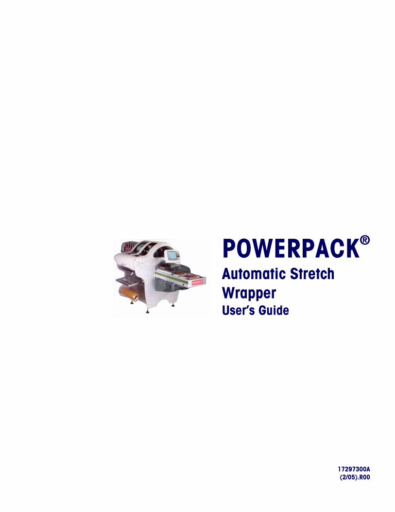
POWERPACK®
Automatic Stretch Wrapper User’s Guide
17297300A (2/05).R00

©Mettler-Toledo, Inc. 2005
No part of this manual may be reproduced or transmitted in any form or by any means, electronic or mechanical, including photocopying and recording, for any purpose without the express written permission of Mettler-Toledo, Inc.
U.S. Government Restricted Rights: This documentation is furnished with Restricted Rights.
Part / Product Name: Part / Model Number: Date:
Provided By:
Customer Name:
Address:
Phone Number: Fax Number:
Your comments:
Do not write in space below. For METTLER TOLEDO use only. Response (if appropriate) and corrective action taken.
PowerPack User's Guide 17297300A
METTLER TOLEDO® and EXACT EQUIPMENT are registered trademarks of Mettler-
Toledo, Inc.
©2005 Mettler-Toledo, Inc. Printed in USA
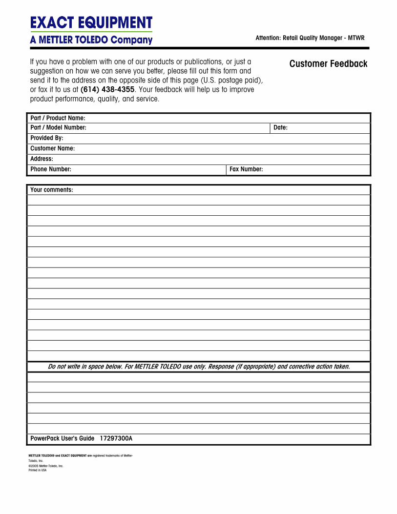
If you have a problem with one of our products or publications, or just a suggestion on how we can serve you better, please fill out this form and send it to the address on the opposite side of this page (U.S. postage paid), or fax it to us at (614) 438-4355. Your feedback will help us to improve product performance, quality, and service.
Customer Feedback
Attention: Retail Quality Manager - MTWR

FOLD THIS FLAP FIRST
BUSINESS REPLY MAILFIRST CLASS PERMIT NO. 414 COLUMBUS, OH
POSTAGE WILL BE PAID BY ADDRESSEE
Mettler-Toledo, Inc. Retail Quality Manager - MTWR P.O. Box 1705 Columbus, OH 43216 USA
NO POSTAGE NECESSARY IF MAILED IN THE UNITED STATES
Please seal with tape.
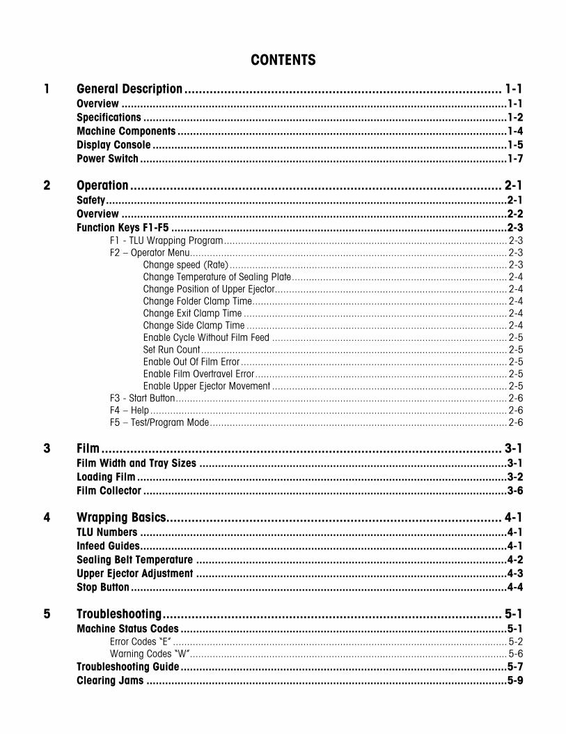
CONTENTS
1 General Description ........................................................................................ 1-1 Overview ............................................................................................................................1-1 Specifications .....................................................................................................................1-2 Machine Components ..........................................................................................................1-4 Display Console ..................................................................................................................1-5 Power Switch ......................................................................................................................1-7
2 Operation....................................................................................................... 2-1 Safety.................................................................................................................................2-1 Overview ............................................................................................................................2-2 Function Keys F1-F5 ............................................................................................................2-3
F1 - TLU Wrapping Program.................................................................................................... 2-3 F2 – Operator Menu................................................................................................................ 2-3
Change speed (Rate).................................................................................................. 2-3 Change Temperature of Sealing Plate............................................................................ 2-4 Change Position of Upper Ejector.................................................................................. 2-4 Change Folder Clamp Time.......................................................................................... 2-4 Change Exit Clamp Time ............................................................................................. 2-4 Change Side Clamp Time ............................................................................................ 2-4 Enable Cycle Without Film Feed ................................................................................... 2-5 Set Run Count ............................................................................................................ 2-5 Enable Out Of Film Error .............................................................................................. 2-5 Enable Film Overtravel Error......................................................................................... 2-5 Enable Upper Ejector Movement ................................................................................... 2-5
F3 - Start Button..................................................................................................................... 2-6 F4 – Help .............................................................................................................................. 2-6 F5 – Test/Program Mode.........................................................................................................2-6
3 Film............................................................................................................... 3-1 Film Width and Tray Sizes ...................................................................................................3-1 Loading Film .......................................................................................................................3-2 Film Collector .....................................................................................................................3-6
4 Wrapping Basics............................................................................................. 4-1 TLU Numbers ......................................................................................................................4-1 Infeed Guides......................................................................................................................4-1 Sealing Belt Temperature ....................................................................................................4-2 Upper Ejector Adjustment ....................................................................................................4-3 Stop Button .........................................................................................................................4-4
5 Troubleshooting.............................................................................................. 5-1 Machine Status Codes .........................................................................................................5-1
Error Codes “E” ...................................................................................................................... 5-2 Warning Codes “W”................................................................................................................ 5-6
Troubleshooting Guide.........................................................................................................5-7 Clearing Jams ....................................................................................................................5-9

6 Cleaning and Maintenance.............................................................................. 6-1 Cleaning.............................................................................................................................6-1
Precautions ........................................................................................................................... 6-1 Daily Cleaning ....................................................................................................................... 6-1 Weekly Cleaning .................................................................................................................... 6-1 Elevator Removal ................................................................................................................... 6-2 Elevator Cleaning ................................................................................................................... 6-3
Lubrication..........................................................................................................................6-4
7 Printed Registered Film Option ........................................................................ 7-1 Film Types ..........................................................................................................................7-1 Determining Film Width.......................................................................................................7-1 Determining Film Length......................................................................................................7-2
8 Product Warranty............................................................................................ 8-1 Warranty Details .................................................................................................................8-1
Chapter 1: General Description Overview
1-1
1 General Description
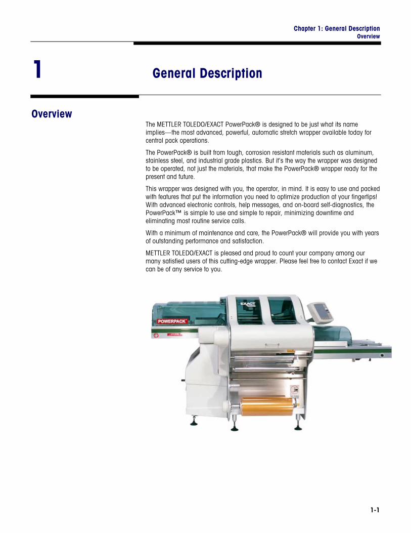
Overview The METTLER TOLEDO/EXACT PowerPack® is designed to be just what its name implies—the most advanced, powerful, automatic stretch wrapper available today for central pack operations.
The PowerPack® is built from tough, corrosion resistant materials such as aluminum, stainless steel, and industrial grade plastics. But it’s the way the wrapper was designed to be operated, not just the materials, that make the PowerPack® wrapper ready for the present and future.
This wrapper was designed with you, the operator, in mind. It is easy to use and packed with features that put the information you need to optimize production at your fingertips! With advanced electronic controls, help messages, and on-board self-diagnostics, the PowerPack™ is simple to use and simple to repair, minimizing downtime and eliminating most routine service calls.
With a minimum of maintenance and care, the PowerPack® will provide you with years of outstanding performance and satisfaction.
METTLER TOLEDO/EXACT is pleased and proud to count your company among our many satisfied users of this cutting-edge wrapper. Please feel free to contact Exact if we can be of any service to you.
PowerPack Operator's Manual
1-2
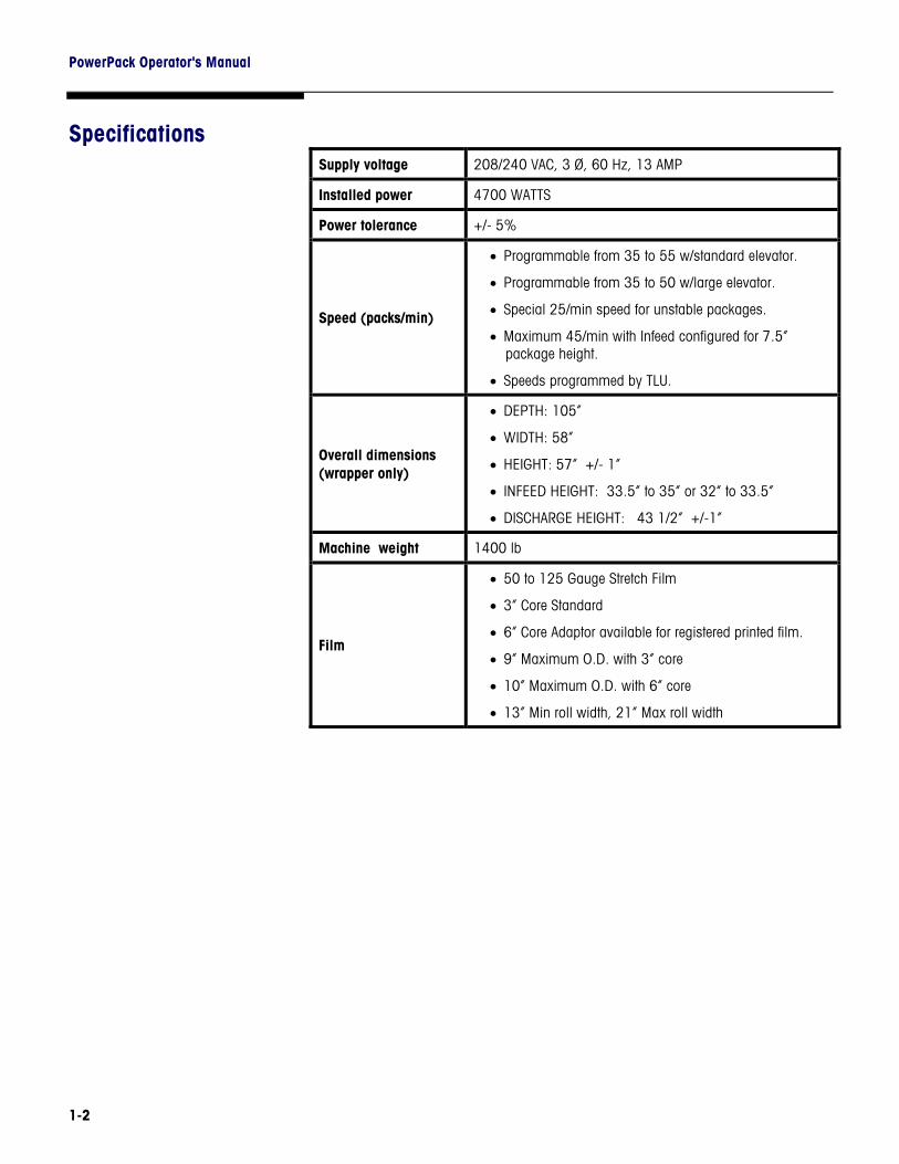
Specifications Supply voltage 208/240 VAC, 3 Ø, 60 Hz, 13 AMP
Installed power 4700 WATTS
Power tolerance +/- 5%
Speed (packs/min)
• Programmable from 35 to 55 w/standard elevator.
• Programmable from 35 to 50 w/large elevator.
• Special 25/min speed for unstable packages.
• Maximum 45/min with Infeed configured for 7.5” package height.
• Speeds programmed by TLU.
Overall dimensions (wrapper only)
• DEPTH: 105”
• WIDTH: 58”
• HEIGHT: 57” +/- 1”
• INFEED HEIGHT: 33.5” to 35” or 32” to 33.5”
• DISCHARGE HEIGHT: 43 1/2” +/-1”
Machine weight 1400 lb
Film
• 50 to 125 Gauge Stretch Film
• 3” Core Standard
• 6” Core Adaptor available for registered printed film.
• 9” Maximum O.D. with 3” core
• 10” Maximum O.D. with 6” core
• 13” Min roll width, 21” Max roll width
Chapter 1: General Description Specifications
1-3
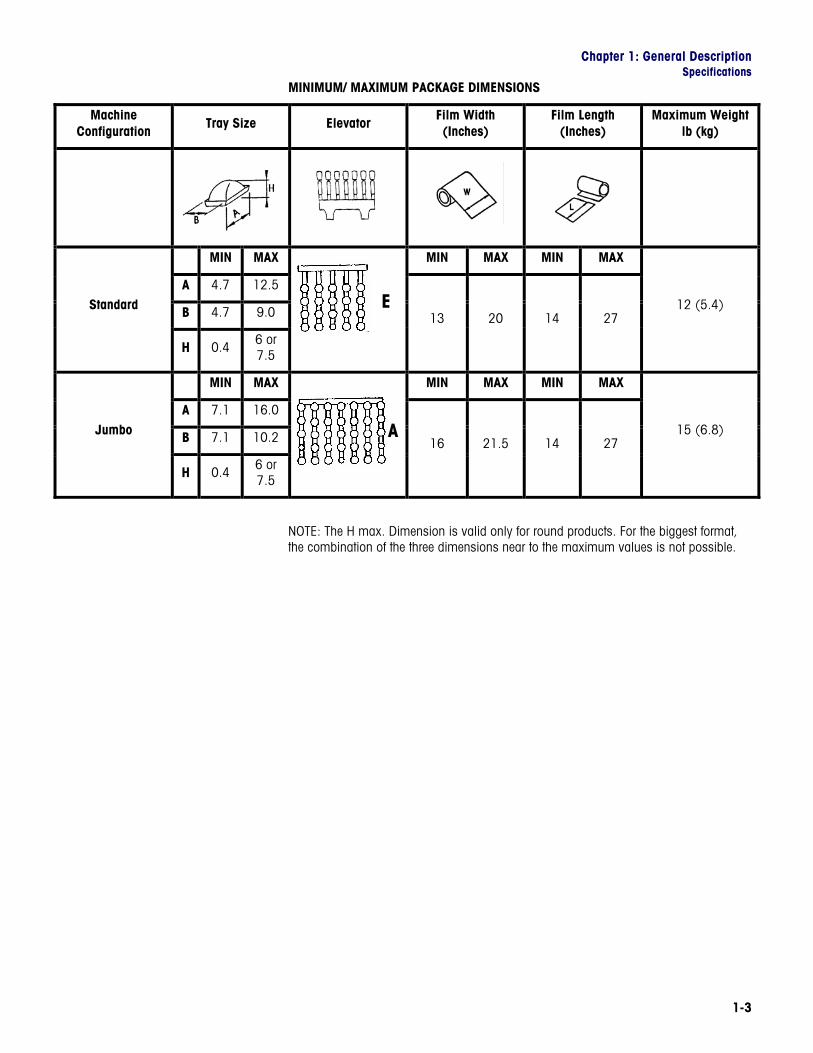
MINIMUM/ MAXIMUM PACKAGE DIMENSIONS
Machine Configuration Tray Size Elevator Film Width
(Inches) Film Length
(Inches) Maximum Weight
lb (kg)
MIN MAX MIN MAX MIN MAX
A 4.7 12.5
B 4.7 9.0 Standard
H 0.4 6 or 7.5
13 20 14 27 12 (5.4)
MIN MAX MIN MAX MIN MAX
A 7.1 16.0
B 7.1 10.2 Jumbo
H 0.4 6 or 7.5
16 21.5 14 27 15 (6.8)
NOTE: The H max. Dimension is valid only for round products. For the biggest format, the combination of the three dimensions near to the maximum values is not possible.
E
A

PowerPack Operator's Manual
1-4
Machine Components
Item Description 1 Main Power Disconnect Switch 2 Serial Plate 3 Upper Right Cover 4 Film Retainer 5 Emergency Stop Push Button 6 Lower Right Door 7 Electronics Cabinet 8 Main Drive (Core) Cover 9 Main Drive (Core) 10 Main Motor 11 Handwheel for Manual Machine
12 Sealing Belt & Sealing Plate 13 Cover for Sealing Plate &
14 Elevator Door 15 Sealing Belt Bulkhead Protector 16 Film Distributor 17 Elevator 18 Upper Ejector 19 Lower Ejector – Pusher Pad 20 Upper Left Cover 21 Front Cover 22 Control Panel with PC Serial
23 Infeed Cover 24 Infeed Maximum Width Guide 25 Infeed Stop Switch 26 Infeed Assembly 27 Adjustable Support Legs 28 Lower Infeed Cover 29 Handwheel for Belt Carriage
30 Film Distributor Unlocking Lever 31 Return Spring for Film Dancer
32 Film Arbor w/Locking Lever 33 Dancer/Tension Roller 34 Film Threading Diagram 35 Film Transfer Belts 36 Film Roll Positioning Guide 37 Locking Clamp for
38 Folder Assembly 39 Film Threading Door

Chapter 1: General Description Display Console
1-5
Display Console
ITEM DESCRIPTION OF FIELDS
1 Machine Number
2 Monitor - Display Software Release
3 Run Count
4 Temperature Setting (1-40)
5 Speed Setting – Rate (Packs Per Minute)
6 Current Carriage Position (1 – 16)
7 Programmed Carriage Position (1 – 16)
8 Machine Status Code
9 Error Messages & Help Screen
10 Maintenance Message
11 Program Information
12 TLU Number/Wrap Program
1
2
3
4
5
6
7
8
9
12
10
11
PowerPack Operator's Manual
1-6
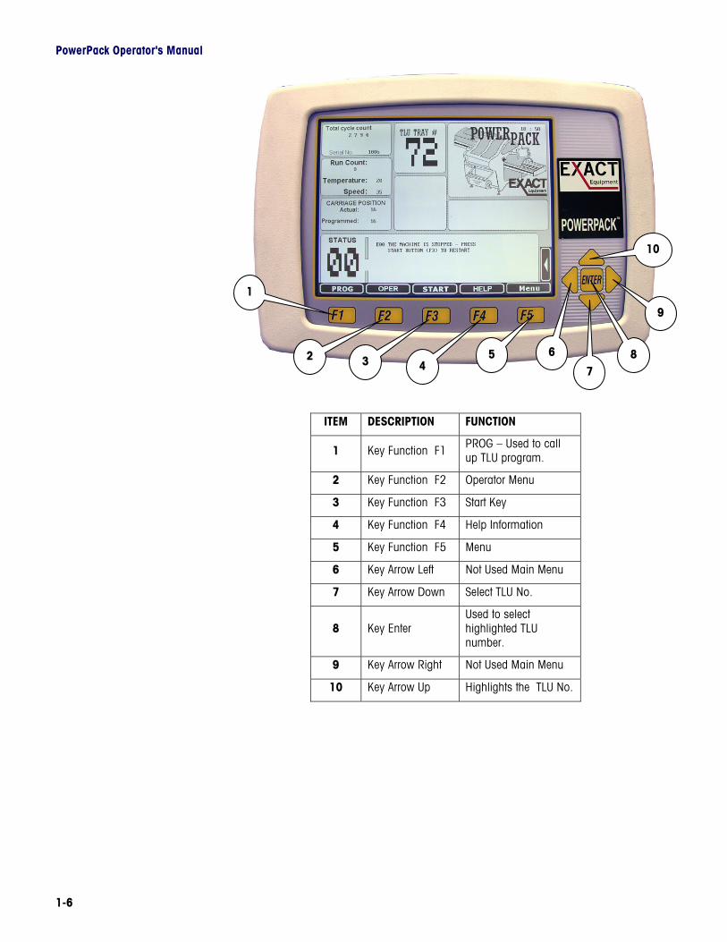
ITEM DESCRIPTION FUNCTION
1 Key Function F1 PROG – Used to call up TLU program.
2 Key Function F2 Operator Menu
3 Key Function F3 Start Key
4 Key Function F4 Help Information
5 Key Function F5 Menu
6 Key Arrow Left Not Used Main Menu
7 Key Arrow Down Select TLU No.
8 Key Enter Used to select highlighted TLU number.
9 Key Arrow Right Not Used Main Menu
10 Key Arrow Up Highlights the TLU No.
1
2 3 5 6
7
9
10
8 4
Chapter 1: General Description Power Switch
1-7
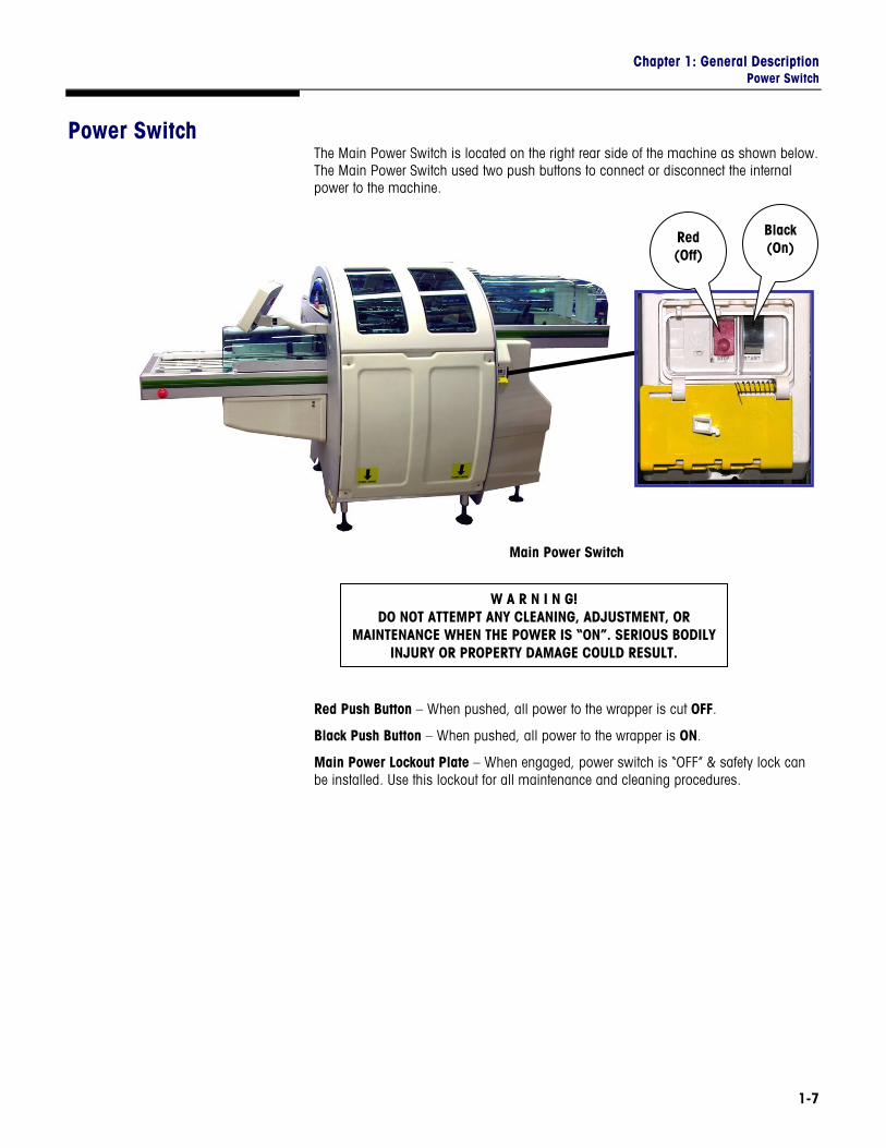
Power Switch The Main Power Switch is located on the right rear side of the machine as shown below. The Main Power Switch used two push buttons to connect or disconnect the internal power to the machine.
Main Power Switch
Red Push Button – When pushed, all power to the wrapper is cut OFF.
Black Push Button – When pushed, all power to the wrapper is ON.
Main Power Lockout Plate – When engaged, power switch is “OFF” & safety lock can be installed. Use this lockout for all maintenance and cleaning procedures.
Red (Off)
Black (On)
W A R N I N G! DO NOT ATTEMPT ANY CLEANING, ADJUSTMENT, OR
MAINTENANCE WHEN THE POWER IS “ON”. SERIOUS BODILY INJURY OR PROPERTY DAMAGE COULD RESULT.

PowerPack Operator's Manual
1-8
EXACT EQUIPMENT For your notes
Chapter 2: Operation Safety
2-1
2 Operation
Safety Warning: Failure to adhere to the following instructions could result in serious bodily injury or property damage.
• Carefully read and understand this manual. • The Sealing Belt is very hot and may reach temperatures of 350°F (180°C) or
more. Never touch the sealing belt while the machine is on. After switching the machine power OFF, allow 20 to 30 minutes for the sealing belt to cool off before touching or cleaning the belt.
• The PowerPack® cycles through a complete wrapping operation when the package sensors are triggered. Be aware of this and keep hands and clothing away from the moving parts of the wrapper when the power is on.
• NEVER attempt to defeat any of the various safety interlocks on the guards. • DO NOT attempt internal adjustments or repairs. Repairs must be performed only by
trained and qualified service personnel. DO NOT allow unqualified personnel to attempt repairs.
• DO NOT allow water to enter the electrical enclosures. Use caution when cleaning and always disconnect the power. REMEMBER: the wrapper is a wipe-down, NOT a wash-down machine.
• NO ONE but qualified operators, age 18 or older, should operate the wrapper. • DO NOT permit distraction of the operator while the wrapper is in use. • DO NOT permit personnel with loose clothing, ties, or jewelry near the wrapper
when in use. • Maintain a firm footing in the area surrounding the wrapper. • Switch the wrapper OFF when not in use. • Keep the wrapper clean and in good running order. • SWITCH OFF and LOCK OUT the wrapper before attempting any cleaning or
maintenance.
PowerPack Operator's Manual
2-2
Overview The following step-by-step procedure is a description of the basic operation of the wrapper. Each individual operation will be described in detail in the pages to follow.
• Be sure all operators are familiar with all necessary safety precautions as described in this manual.
• Check the wrapper for any obstruction or product left anywhere in, on, or around the wrapper that may affect its use.
• Verify that the stop button is depressed. • Push the black button on the main power switch to turn the main power “ON”. • Allow time (5-10 minutes) for the sealing plate to warm up. • Using the key arrow down or up, select the appropriate tray look up (TLU) program. • Be sure that the film is present on the arbor, properly threaded, of adequate size,
and in the correct position on the arbor. • Verify that all covers and guards are in place and closed. • Twist to release the STOP button. • Press the START button F3 on the control panel. • Place the trays centered on the infeed and begin wrapping. • The Emergency Stop Button, located on the Infeed can be pressed at any time to
stop the machine.
IMPORTANT: Once a tray is placed on the infeed, leave it alone. The wrapper has safety interlocks that will stop the machine should the package be severely misaligned.
Chapter 2: Operation Function Keys F1-F5
2-3
Function Keys F1-F5
F1 - TLU Wrapping Program
F1 is used to activate the “PROG” command to select the TLU (Tray Look Up). During this phase, the “PROG” window on the screen is highlighted to show that the program select option is working.
To change the TLU value, use the keys “ARROW UP” and “ARROW DOWN.” To confirm, press “ENTER” or function key “F1.” At this point, the TLU in top center of screen is changed and the “PROG” window on the screen returns to the original shading. The machine performs an automatic setup according to the new TLU (for example, film length, speed, upper ejector height, clamp settings, etc.)
Note 1: From the time a new pack selection is made to the time the machine is ready to wrap the new tray, the infeed does not run.
Note 2: If F1 is pressed and a new selection is not made within a few seconds, the original pack program is brought back and the programmed pack selection phase is closed.
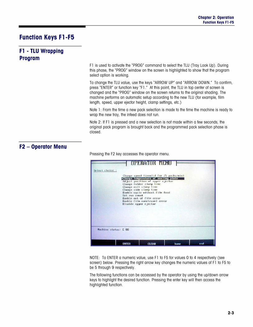
F2 – Operator Menu Pressing the F2 key accesses the operator menu.
NOTE: To ENTER a numeric value, use F1 to F5 for values 0 to 4 respectively (see screen) below. Pressing the right arrow key changes the numeric values of F1 to F5 to be 5 through 9 respectively.
The following functions can be accessed by the operator by using the up/down arrow keys to highlight the desired function. Pressing the enter key will then access the highlighted function.
PowerPack Operator's Manual
2-4
Change speed (Rate) For special circumstances, the set working speed of the current TLU program can be temporarily changed. The speed can be changed from 35 cycles/min to +/- 5 cycles/min compared to the programmed speed. The current value is displayed. It can be changed by using the function and left/right arrow keys as noted above. Press enter to confirm the new value, press clear to exit.
Change Temperature of Sealing Plate For special circumstances, the working temperature of the sealing plate can be temporarily changed. The current value is displayed. It can be changed by using the function and left/right arrow keys as noted above. Press enter to confirm the new value, press clear to exit.
Change Position of Upper Ejector For special circumstances, the upper ejector position can be temporarily changed. The current value is displayed. It can be changed by using the function and left/right arrow keys as noted above. Press enter to confirm the new value, press clear to exit.
Change Folder Clamp Time For special circumstances, it is possible to temporarily change the clamp opening time (0-20) from what it is set in the TLU program. The current value is displayed. It can be changed by using the function and left/right arrow keys as noted above. Press enter to confirm the new value, press clear to exit.
Change Exit Clamp Time For special cases, it is possible to temporarily change the exit clamps opening time (0-20) compared to the setting in the TLU program. The current value is displayed. It can be changed by using the function and left/right arrow keys as noted above. Press enter to confirm the new value, press clear to exit.
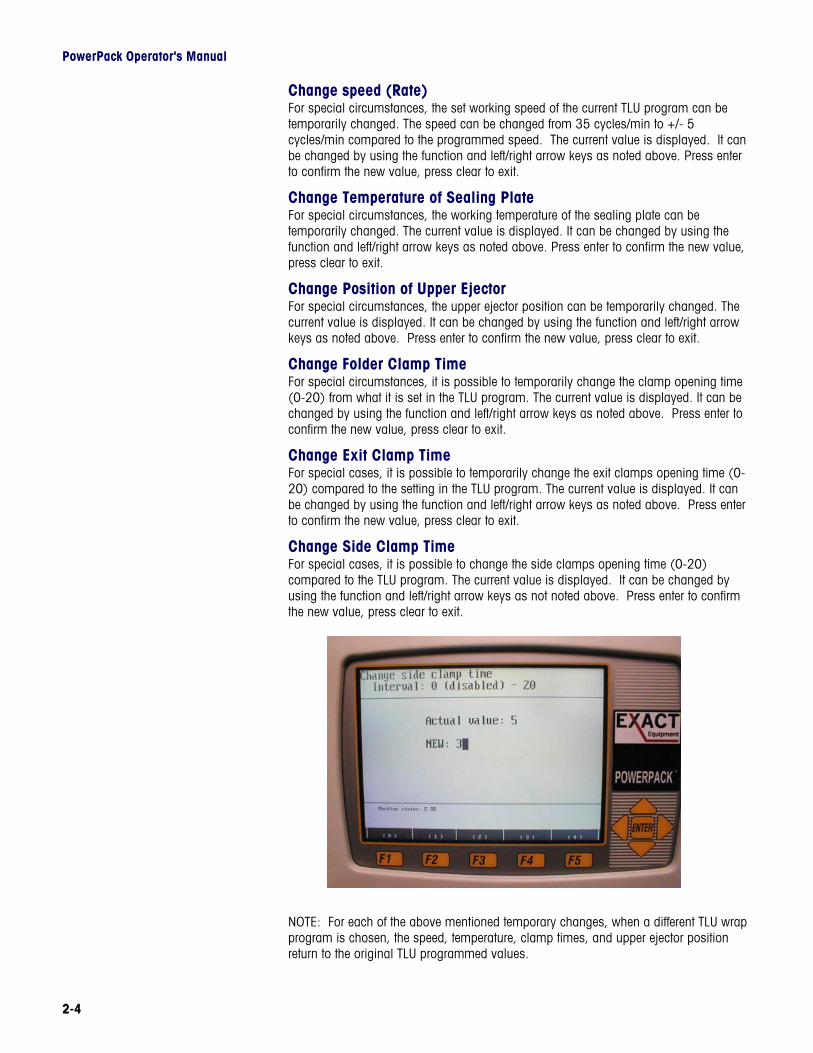
Change Side Clamp Time For special cases, it is possible to change the side clamps opening time (0-20) compared to the TLU program. The current value is displayed. It can be changed by using the function and left/right arrow keys as not noted above. Press enter to confirm the new value, press clear to exit.
NOTE: For each of the above mentioned temporary changes, when a different TLU wrap program is chosen, the speed, temperature, clamp times, and upper ejector position return to the original TLU programmed values.
Chapter 2: Operation Function Keys F1-F5
2-5
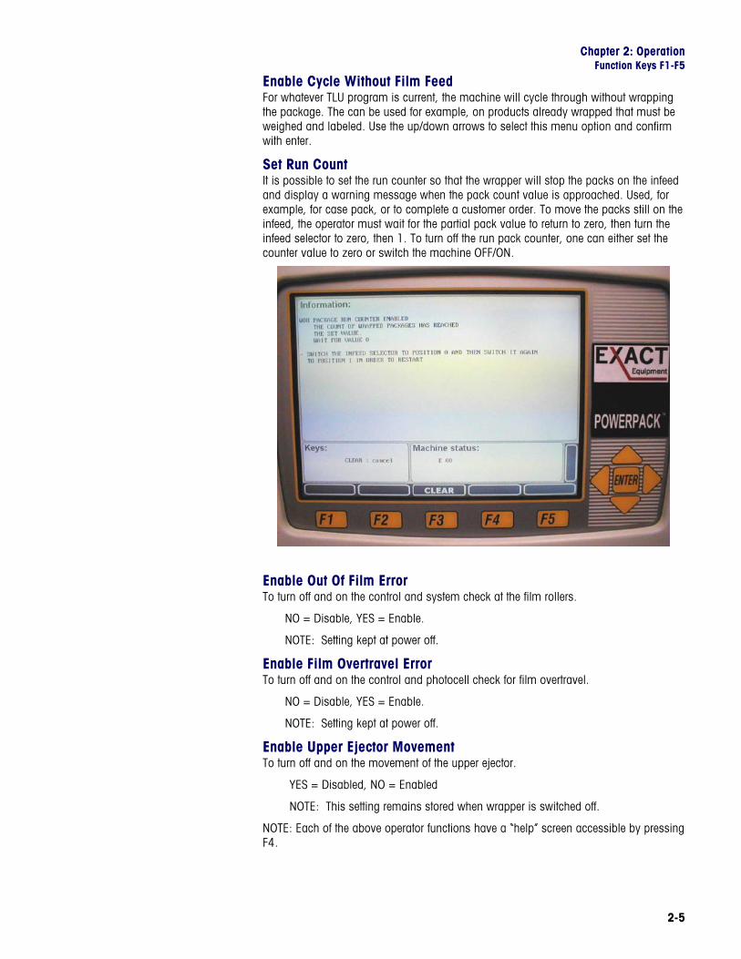
Enable Cycle Without Film Feed For whatever TLU program is current, the machine will cycle through without wrapping the package. The can be used for example, on products already wrapped that must be weighed and labeled. Use the up/down arrows to select this menu option and confirm with enter.
Set Run Count It is possible to set the run counter so that the wrapper will stop the packs on the infeed and display a warning message when the pack count value is approached. Used, for example, for case pack, or to complete a customer order. To move the packs still on the infeed, the operator must wait for the partial pack value to return to zero, then turn the infeed selector to zero, then 1. To turn off the run pack counter, one can either set the counter value to zero or switch the machine OFF/ON.
Enable Out Of Film Error To turn off and on the control and system check at the film rollers.
NO = Disable, YES = Enable.
NOTE: Setting kept at power off.
Enable Film Overtravel Error To turn off and on the control and photocell check for film overtravel.
NO = Disable, YES = Enable.
NOTE: Setting kept at power off.
Enable Upper Ejector Movement To turn off and on the movement of the upper ejector.
YES = Disabled, NO = Enabled
NOTE: This setting remains stored when wrapper is switched off.
NOTE: Each of the above operator functions have a “help” screen accessible by pressing F4.
PowerPack Operator's Manual
2-6
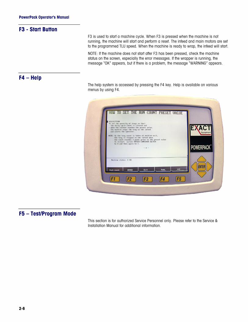
F3 - Start Button F3 is used to start a machine cycle. When F3 is pressed when the machine is not running, the machine will start and perform a reset. The infeed and main motors are set to the programmed TLU speed. When the machine is ready to wrap, the infeed will start.
NOTE: If the machine does not start after F3 has been pressed, check the machine status on the screen, especially the error messages. If the wrapper is running, the message “OK” appears, but if there is a problem, the message “WARNING” appears.
F4 – Help The help system is accessed by pressing the F4 key. Help is available on various menus by using F4.
F5 – Test/Program Mode This section is for authorized Service Personnel only. Please refer to the Service & Installation Manual for additional information.
Chapter 3: Film Film Width and Tray Sizes
3-1
3 Film
Film Width and Tray Sizes
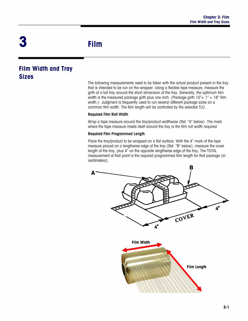
The following measurements need to be taken with the actual product present in the tray that is intended to be run on the wrapper. Using a flexible tape measure, measure the girth of a full tray around the short dimension of the tray. Generally, the optimum film width is the measured package girth plus one inch. (Package girth 15”+ 1” = 16” film width.) Judgment is frequently used to run several different package sizes on a common film width. The film length will be controlled by the selected TLU.
Required Film Roll Width
Wrap a tape measure around the tray/product widthwise (Ref. “A” below). The mark where the tape measure meets itself around the tray is the film roll width required.
Required Film Programmed Length
Place the tray/product to be wrapped on a flat surface. With the 4” mark of the tape measure placed on a lengthwise edge of the tray (Ref. “B” below), measure the cover length of the tray, plus 4” on the opposite lengthwise edge of the tray. The TOTAL measurement at that point is the required programmed film length for that package (in centimeters).
Film Width
Film Length
PowerPack Operator's Manual
3-2
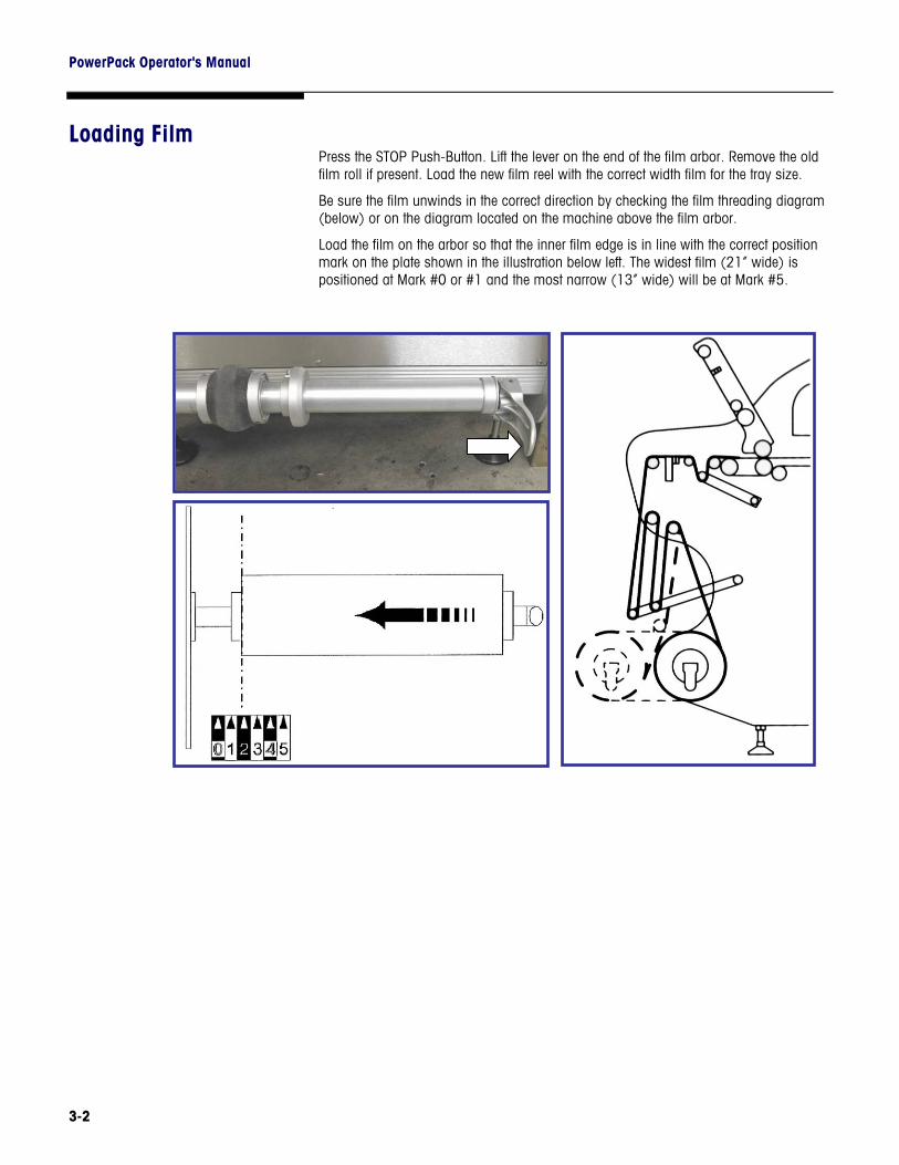
Loading Film Press the STOP Push-Button. Lift the lever on the end of the film arbor. Remove the old film roll if present. Load the new film reel with the correct width film for the tray size.
Be sure the film unwinds in the correct direction by checking the film threading diagram (below) or on the diagram located on the machine above the film arbor.
Load the film on the arbor so that the inner film edge is in line with the correct position mark on the plate shown in the illustration below left. The widest film (21” wide) is positioned at Mark #0 or #1 and the most narrow (13” wide) will be at Mark #5.
Chapter 3: Film Loading Film
3-3
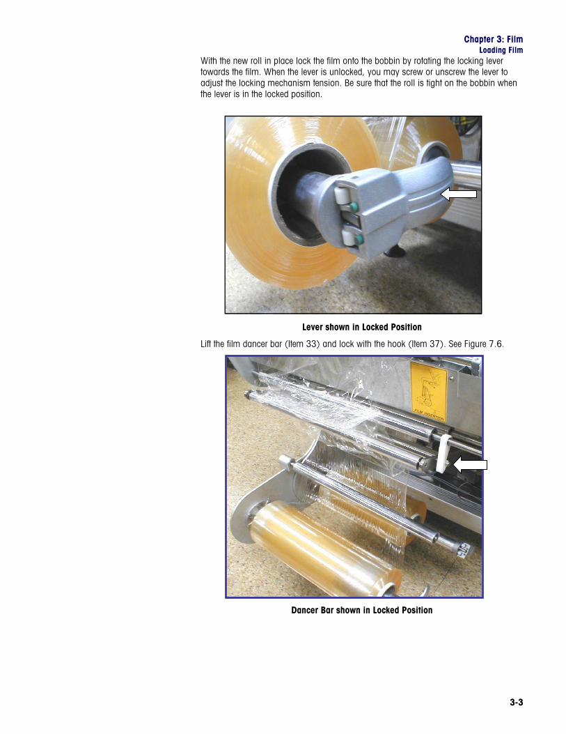
With the new roll in place lock the film onto the bobbin by rotating the locking lever towards the film. When the lever is unlocked, you may screw or unscrew the lever to adjust the locking mechanism tension. Be sure that the roll is tight on the bobbin when the lever is in the locked position.
Lever shown in Locked Position
Lift the film dancer bar (Item 33) and lock with the hook (Item 37). See Figure 7.6.
Dancer Bar shown in Locked Position
PowerPack Operator's Manual
3-4
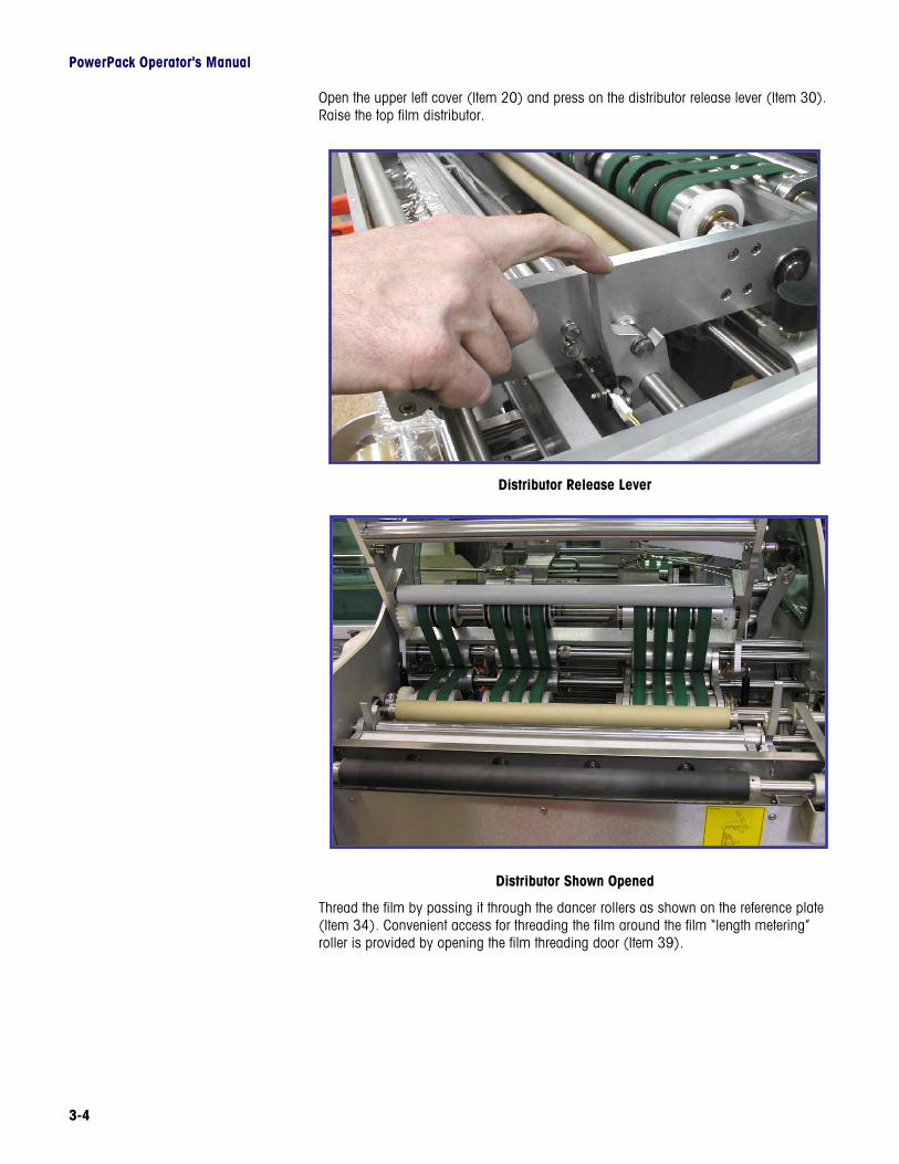
Open the upper left cover (Item 20) and press on the distributor release lever (Item 30). Raise the top film distributor.
Distributor Release Lever
Distributor Shown Opened
Thread the film by passing it through the dancer rollers as shown on the reference plate (Item 34). Convenient access for threading the film around the film “length metering” roller is provided by opening the film threading door (Item 39).
Chapter 3: Film Loading Film
3-5
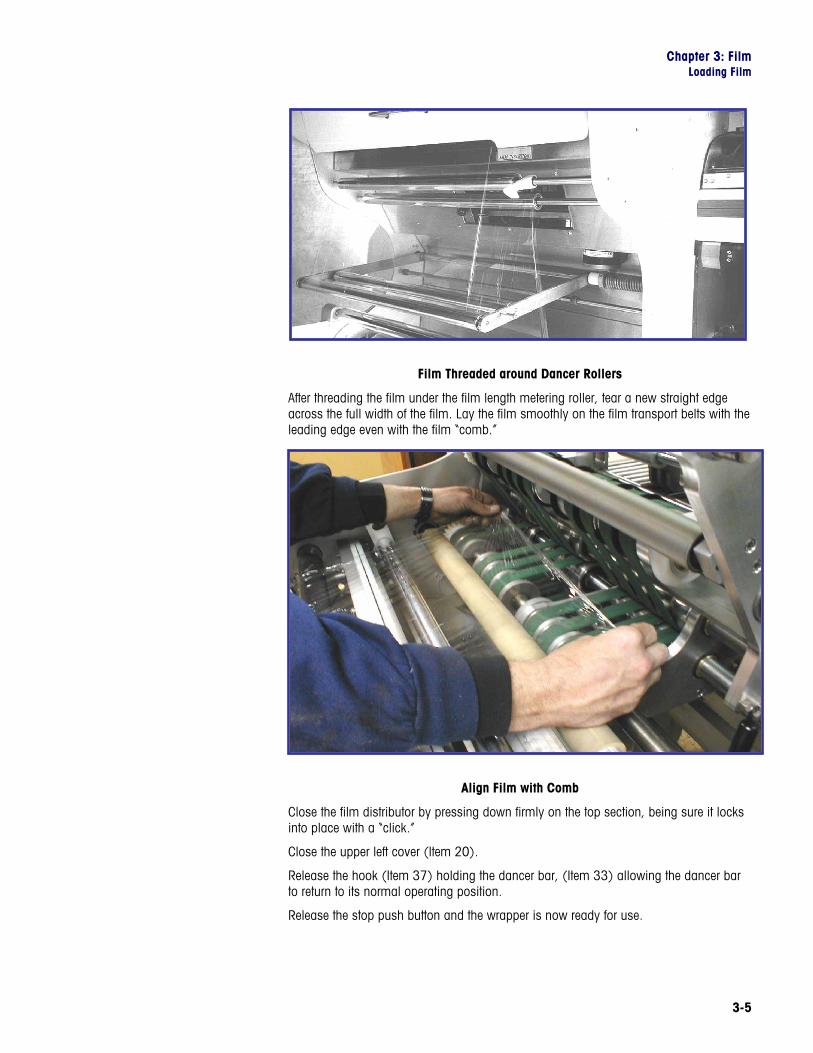
Film Threaded around Dancer Rollers
After threading the film under the film length metering roller, tear a new straight edge across the full width of the film. Lay the film smoothly on the film transport belts with the leading edge even with the film “comb.”
Align Film with Comb
Close the film distributor by pressing down firmly on the top section, being sure it locks into place with a “click.”
Close the upper left cover (Item 20).
Release the hook (Item 37) holding the dancer bar, (Item 33) allowing the dancer bar to return to its normal operating position.
Release the stop push button and the wrapper is now ready for use.
PowerPack Operator's Manual
3-6
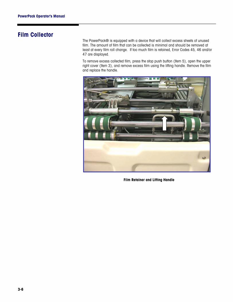
Film Collector The PowerPack® is equipped with a device that will collect excess sheets of unused film. The amount of film that can be collected is minimal and should be removed at least at every film roll change. If too much film is retained, Error Codes 45, 46 and/or 47 are displayed.
To remove excess collected film, press the stop push button (Item 5), open the upper right cover (Item 3), and remove excess film using the lifting handle. Remove the film and replace the handle.
Film Retainer and Lifting Handle
Chapter 4: Wrapping Basics TLU Numbers
4-1
4 Wrapping Basics
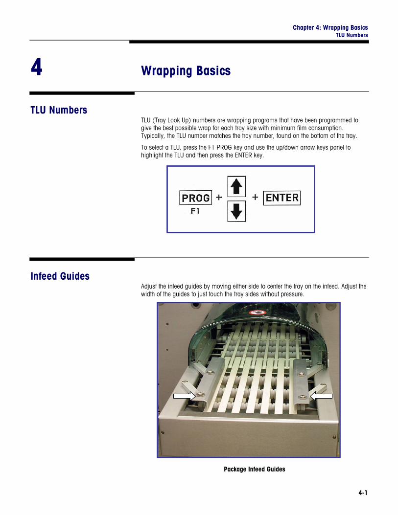
TLU Numbers TLU (Tray Look Up) numbers are wrapping programs that have been programmed to give the best possible wrap for each tray size with minimum film consumption. Typically, the TLU number matches the tray number, found on the bottom of the tray.
To select a TLU, press the F1 PROG key and use the up/down arrow keys panel to highlight the TLU and then press the ENTER key.
Infeed Guides Adjust the infeed guides by moving either side to center the tray on the infeed. Adjust the width of the guides to just touch the tray sides without pressure.
Package Infeed Guides
PowerPack Operator's Manual
4-2
The PowerPack® can wrap products at speeds ranging from 35 to 55 packages per minute (standard elevator). The wrapping speed is set in each program and is shown on the display panel. For unstable or fragile packages, a special speed of 25 packages per minute is available to handle the product gently without tipping.
Maximum wrapping throughput can be attained by placing the trays in the center of the infeed with a distance between trays of not more than 10 inches and not less than 2 inches. The infeed will automatically index the packages into the machine at the proper point in the cycle.
Sealing Belt Temperature
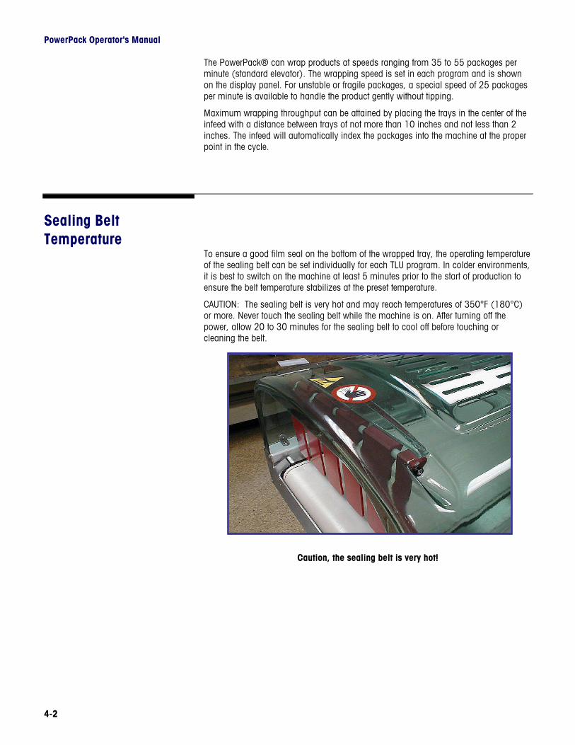
To ensure a good film seal on the bottom of the wrapped tray, the operating temperature of the sealing belt can be set individually for each TLU program. In colder environments, it is best to switch on the machine at least 5 minutes prior to the start of production to ensure the belt temperature stabilizes at the preset temperature.
CAUTION: The sealing belt is very hot and may reach temperatures of 350°F (180°C) or more. Never touch the sealing belt while the machine is on. After turning off the power, allow 20 to 30 minutes for the sealing belt to cool off before touching or cleaning the belt.
Caution, the sealing belt is very hot!
Chapter 4: Wrapping Basics Upper Ejector Adjustment
4-3
Upper Ejector Adjustment
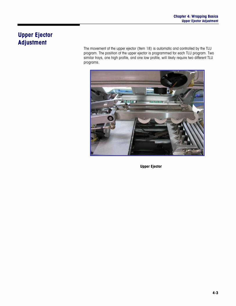
The movement of the upper ejector (Item 18) is automatic and controlled by the TLU program. The position of the upper ejector is programmed for each TLU program. Two similar trays, one high profile, and one low profile, will likely require two different TLU programs.
Upper Ejector
PowerPack Operator's Manual
4-4
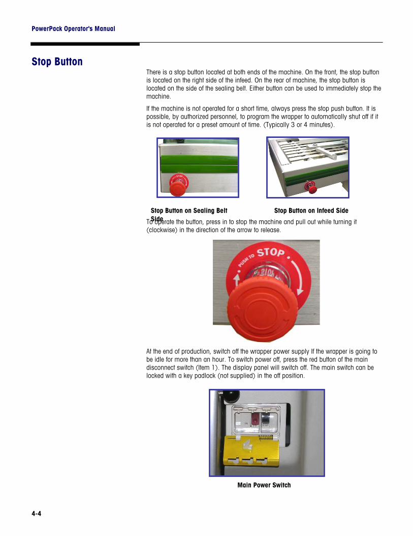
Stop Button There is a stop button located at both ends of the machine. On the front, the stop button is located on the right side of the infeed. On the rear of machine, the stop button is located on the side of the sealing belt. Either button can be used to immediately stop the machine.
If the machine is not operated for a short time, always press the stop push button. It is possible, by authorized personnel, to program the wrapper to automatically shut off if it is not operated for a preset amount of time. (Typically 3 or 4 minutes).
To operate the button, press in to stop the machine and pull out while turning it (clockwise) in the direction of the arrow to release.
At the end of production, switch off the wrapper power supply If the wrapper is going to be idle for more than an hour. To switch power off, press the red button of the main disconnect switch (Item 1). The display panel will switch off. The main switch can be locked with a key padlock (not supplied) in the off position.
Main Power Switch
Stop Button on Sealing Belt Side
Stop Button on Infeed Side
Chapter 5: Troubleshooting Machine Status Codes
5-1
5 Troubleshooting
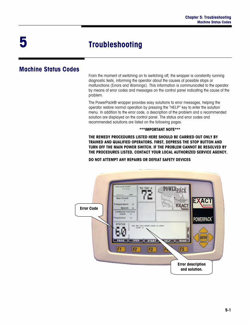
Machine Status Codes From the moment of switching on to switching off, the wrapper is constantly running diagnostic tests, informing the operator about the causes of possible stops or malfunctions (Errors and Warnings). This information is communicated to the operator by means of error codes and messages on the control panel indicating the cause of the problem.
The PowerPack® wrapper provides easy solutions to error messages, helping the operator restore normal operation by pressing the “HELP” key to enter the solution menu. In addition to the error code, a description of the problem and a recommended solution are displayed on the control panel. The status and error codes and recommended solutions are listed on the following pages.
***IMPORTANT NOTE***
THE REMEDY PROCEDURES LISTED HERE SHOULD BE CARRIED OUT ONLY BY TRAINED AND QUALIFIED OPERATORS. FIRST, DEPRESS THE STOP BUTTON AND TURN OFF THE MAIN POWER SWITCH. IF THE PROBLEM CANNOT BE RESOLVED BY THE PROCEDURES LISTED, CONTACT YOUR LOCAL AUTHORIZED SERVICE AGENCY.
DO NOT ATTEMPT ANY REPAIRS OR DEFEAT SAFETY DEVICES
Error Code
Error description and solution.
PowerPack Operator's Manual
5-2
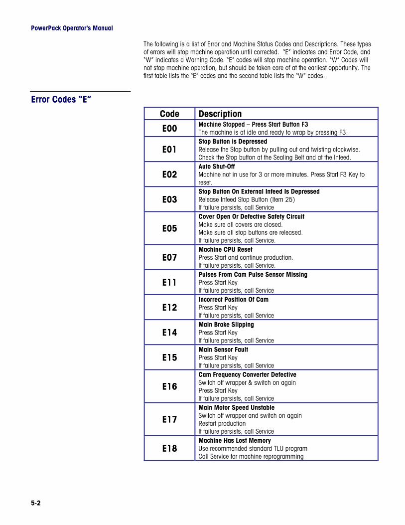
The following is a list of Error and Machine Status Codes and Descriptions. These types of errors will stop machine operation until corrected. “E” indicates and Error Code, and “W” indicates a Warning Code. “E” codes will stop machine operation. “W” Codes will not stop machine operation, but should be taken care of at the earliest opportunity. The first table lists the “E” codes and the second table lists the “W” codes.
Error Codes “E”
Code Description
E00 Machine Stopped – Press Start Button F3 The machine is at idle and ready to wrap by pressing F3.
E01 Stop Button is Depressed Release the Stop button by pulling out and twisting clockwise. Check the Stop button at the Sealing Belt and at the Infeed.
E02 Auto Shut-Off Machine not in use for 3 or more minutes. Press Start F3 Key to reset.
E03 Stop Button On External Infeed Is Depressed Release Infeed Stop Button (Item 25) If failure persists, call Service
E05 Cover Open Or Defective Safety Circuit Make sure all covers are closed. Make sure all stop buttons are released. If failure persists, call Service.
E07 Machine CPU Reset Press Start and continue production. If failure persists, call Service.
E11 Pulses From Cam Pulse Sensor Missing Press Start Key If failure persists, call Service
E12 Incorrect Position Of Cam Press Start Key If failure persists, call Service
E14 Main Brake Slipping Press Start Key If failure persists, call Service
E15 Main Sensor Fault Press Start Key If failure persists, call Service
E16 Cam Frequency Converter Defective Switch off wrapper & switch on again Press Start Key If failure persists, call Service
E17 Main Motor Speed Unstable Switch off wrapper and switch on again Restart production If failure persists, call Service
E18 Machine Has Lost Memory Use recommended standard TLU program Call Service for machine reprogramming

Chapter 5: Troubleshooting Machine Status Codes
5-3
Code Description
E19
Speed Higher Than Maximum Allowed Select correct TLU program Enter temporary speed correction If failure persists, call Service Restart production If failure persists, call Service
E20 Pulses Missing From Infeed Sensor Press Start Key If failure persists, call Service
E21
Infeed Motor Speed Unstable Switch wrapper off & switch on again Restart production If failure persists, call Service If failure persists, call Service
E22 Infeed Frequency Converter Defective Switch wrapper off & switch on again Restart production If failure persists, call Service
E23
Packages On Infeed To Close Trays returned by reversing infeed motor Remove & reload trays at outside of infeed cover If failure persists, call Service If failure persists, call Service
E24
Machine (Infeed) Photocell Blocked Remove all packages from the infeed Clean machine photocell & reflector If failure persists, call Service Press Start Key
E30 Zero Setting Of Upper Ejector Failed Switch machine OFF/Switch ON Press Start Key If failure persists, call Service
E40 Pulses From Film Feed Sensor Missing Check film reel for presence & proper placement Press Start Key
E41 Film Centering Movement Has Finished Too Late Press Start Key If failure persists, call Service
E42 Zero Setting Of Film Length Motor Failed Switch wrapper off & switch on again Press Start Key If failure persists, call Service
E44
Film Reel—Out Of Film Replace empty reel Film broken, reload film Film wrapped around first roller-reload Check that metal roller after knife turns freely Clean & lubricate metal roller Check and clean “film presence” sensor If failure persists, call Service
PowerPack Operator's Manual
5-4
Code Description
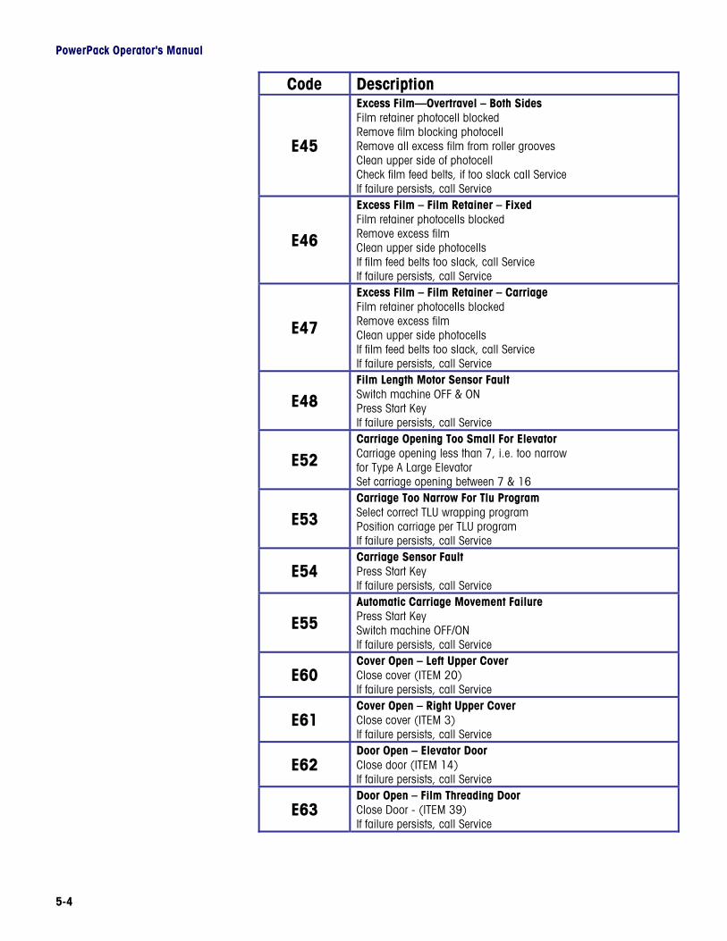
E45
Excess Film—Overtravel – Both Sides Film retainer photocell blocked Remove film blocking photocell Remove all excess film from roller grooves Clean upper side of photocell Check film feed belts, if too slack call Service If failure persists, call Service
E46
Excess Film – Film Retainer – Fixed Film retainer photocells blocked Remove excess film Clean upper side photocells If film feed belts too slack, call Service If failure persists, call Service
E47
Excess Film – Film Retainer – Carriage Film retainer photocells blocked Remove excess film Clean upper side photocells If film feed belts too slack, call Service If failure persists, call Service
E48 Film Length Motor Sensor Fault Switch machine OFF & ON Press Start Key If failure persists, call Service
E52 Carriage Opening Too Small For Elevator Carriage opening less than 7, i.e. too narrow for Type A Large Elevator Set carriage opening between 7 & 16
E53 Carriage Too Narrow For Tlu Program Select correct TLU wrapping program Position carriage per TLU program If failure persists, call Service
E54 Carriage Sensor Fault Press Start Key If failure persists, call Service
E55 Automatic Carriage Movement Failure Press Start Key Switch machine OFF/ON If failure persists, call Service
E60 Cover Open – Left Upper Cover Close cover (ITEM 20) If failure persists, call Service
E61 Cover Open – Right Upper Cover Close cover (ITEM 3) If failure persists, call Service
E62 Door Open – Elevator Door Close door (ITEM 14) If failure persists, call Service
E63 Door Open – Film Threading Door Close Door - (ITEM 39) If failure persists, call Service
Chapter 5: Troubleshooting Machine Status Codes
5-5
Code Description
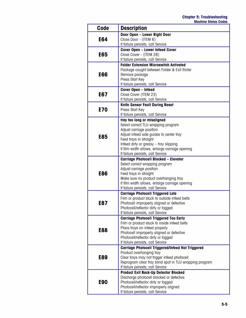
E64 Door Open – Lower Right Door Close Door - (ITEM 6) If failure persists, call Service
E65 Cover Open – Lower Infeed Cover Close Cover - (ITEM 28) If failure persists, call Service
E66
Folder Extension Microswitch Activated Package caught between Folder & Exit Roller Remove package Press Start Key If failure persists, call Service
E67 Cover Open – Infeed Close Cover (ITEM 23) If failure persists, call Service
E70 Knife Sensor Fault During Reset Press Start Key If failure persists, call Service
E85
tray too long or misaligned Select correct TLU wrapping program Adjust carriage position Adjust infeed side guides to center tray Feed trays in straight Infeed dirty or greasy – tray slipping If film width allows, enlarge carriage opening If failure persists, call Service
E86
Carriage Photocell Blocked – Elevator Select correct wrapping program Adjust carriage position Feed trays in straight Make sure no product overhanging tray If film width allows, enlarge carriage opening If failure persists, call Service
E87
Carriage Photocell Triggered Late Film or product stuck to outside infeed belts Photocell improperly aligned or defective Photocell/reflector dirty or fogged If failure persists, call Service
E88
Carriage Photocell Triggered Too Early Film or product stuck to inside infeed belts Place trays on infeed properly Photocell improperly aligned or defective Photocell/reflector dirty or fogged If failure persists, call Service
E89
Carriage Photocell Triggered/Infeed Not Triggered Product overhanging tray Clear trays may not trigger infeed photocell Reprogram clear tray blind spot in TLU wrapping program If failure persists, call Service
E90
Product Exit Back-Up Detector Blocked Discharge photocell blocked or defective Photocell/reflector dirty or fogged Photocell/reflector improperly aligned If failure persists, call Service
PowerPack Operator's Manual
5-6
Code Description
E91
Printed Film Photocell Blocked Photocell blocked or defective Photocell/reflector dirty or fogged Photocell/reflector improperly aligned If failure persists, call Service
E92
Registration Mark Not Found (Printed Film) Film not centered or aligned w/respect to sensor Photocell/reflector improperly aligned Photocell blocked or defective If failure persists, call Service
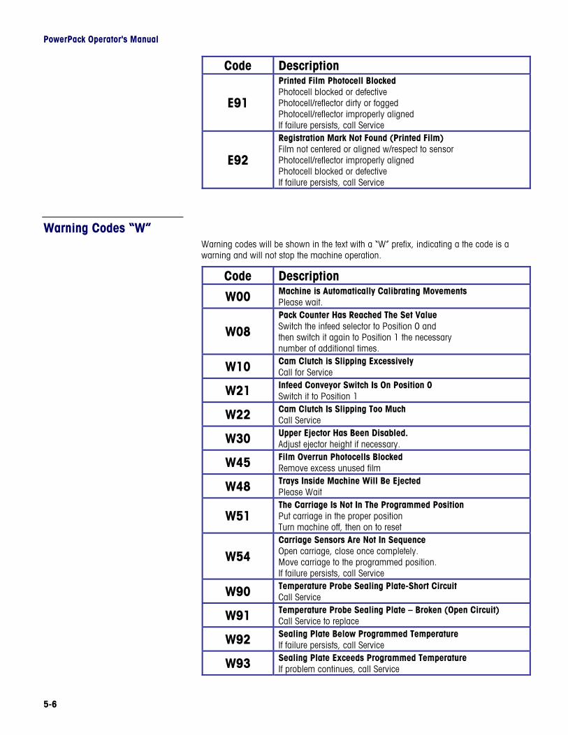
Warning Codes “W” Warning codes will be shown in the text with a “W” prefix, indicating a the code is a warning and will not stop the machine operation.
Code Description
W00 Machine is Automatically Calibrating Movements Please wait.
W08 Pack Counter Has Reached The Set Value Switch the infeed selector to Position 0 and then switch it again to Position 1 the necessary number of additional times.
W10 Cam Clutch is Slipping Excessively Call for Service
W21 Infeed Conveyor Switch Is On Position 0 Switch it to Position 1
W22 Cam Clutch Is Slipping Too Much Call Service
W30 Upper Ejector Has Been Disabled. Adjust ejector height if necessary.
W45 Film Overrun Photocells Blocked Remove excess unused film
W48 Trays Inside Machine Will Be Ejected Please Wait
W51 The Carriage Is Not In The Programmed Position Put carriage in the proper position Turn machine off, then on to reset
W54 Carriage Sensors Are Not In Sequence Open carriage, close once completely. Move carriage to the programmed position. If failure persists, call Service
W90 Temperature Probe Sealing Plate-Short Circuit Call Service
W91 Temperature Probe Sealing Plate – Broken (Open Circuit) Call Service to replace
W92 Sealing Plate Below Programmed Temperature If failure persists, call Service
W93 Sealing Plate Exceeds Programmed Temperature If problem continues, call Service

Chapter 5: Troubleshooting Troubleshooting Guide
5-7
W94 Sealing Plate Has Not Yet Reached Set Temperature Please Wait
W95 Tray Stopped On Infeed – Device #1 Error Please wait until machine starts again
W96 Tray Stopped On Infeed – Device #2 Error Please wait until machine starts again
W97 Tray Stopped On Infeed – Device #3 Error Please wait until machine starts again
W99 Tray Stopped On Infeed – Exit Photocell Blocked Unblock machine exit photocell Please wait until machine starts again
Troubleshooting Guide Caution: The solutions that are provided in this section should only be attempted by fully trained operators. If the solutions provided do not rectify the problem, call your local authorized service company for assistance and/or service.
Fault Possible Cause Solution
No Main Power Check main power switch Display panel does not light when main switch is turned on.
Brightness control set incorrectly
Turn brightness control on rear of display.
Sealing belt temperature too low
Increase temperature by using button or change programmed temperature in TLU.
Package not sealed correctly, loose film
on tray bottom. Incorrect film used Replace with proper type of
film.
Package has holes in the film or bottom
burned.
Sealing belt temperature too high.
Decrease temperature using button or change programmed temperature in TLU.
Package is open on two sides.
TLU wrap program not suitable for product being wrapped.
Select another TLU program.
Film roll positioned incorrectly.
Check and reposition film roll on arbor.
TLU wrap program not suitable for product being wrapped.
Select another TLU program.
Package is open on one side.
Package not centered on infeed.
Readjust the centering guides on infeed.
Film roll positioned incorrectly or incorrect film width.
Check and reposition film roll on arbor or use a film width more suitable for the tray being wrapped.
Package is open on the bottom side,
lengthwise. TLU wrap program not suitable for product being wrapped.
Select another TLU program.

PowerPack Operator's Manual
5-8
Fault Possible Cause Solution
Film roll positioned incorrectly or incorrect film width.
Check and reposition film roll on arbor or use a film width more suitable for the tray being wrapped.
Film loose around package.
TLU wrap program not suitable for product being wrapped.
Select another TLU program.
Film width too wide or roll positioned incorrectly.
Use a film width more suitable to the size of tray wrapped.
Package too high or unstable.
Reposition product in the tray or use a tray more suitable to the product being wrapped.
Upper ejector height incorrect. Adjust the upper ejector position.
Package turns over at discharge.
Incorrect TLU wrap program. Select a different TLU.
Defective film (irregular thickness, unsuitable film).
Replace film. Film tears close to the roll while unwinding. Film incorrectly loaded or
threaded. Reload and thread the film.
Use a tray that more closely matches the product dimensions.
The tray is too large or unsuitable for the product being wrapped. If the machine is jammed,
use the handwheel to remove package.
Incorrect TLU wrap program. Select a different TLU.
Tray is not sufficiently rigid or unsuitable for the product.
Use more rigid trays or better quality trays.
The tray is crushed during ejection or
film folding.
Incorrect film type. Replace with suitable film.
Chapter 5: Troubleshooting Clearing Jams
5-9
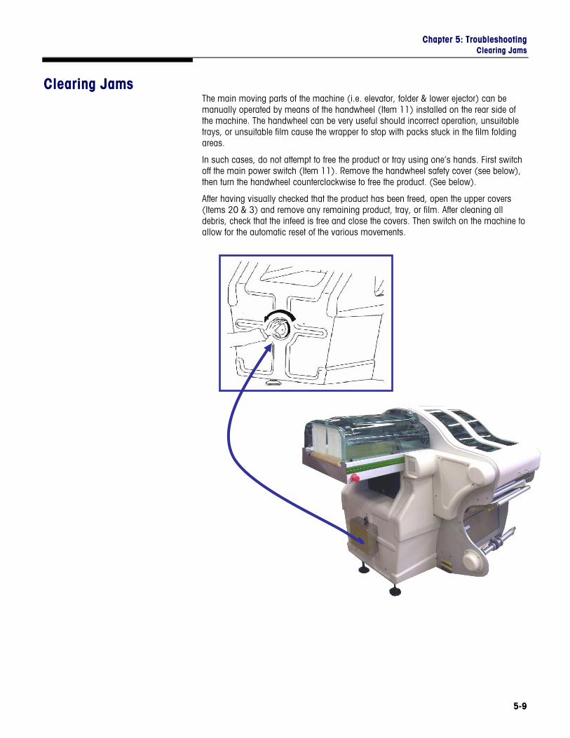
Clearing Jams The main moving parts of the machine (i.e. elevator, folder & lower ejector) can be manually operated by means of the handwheel (Item 11) installed on the rear side of the machine. The handwheel can be very useful should incorrect operation, unsuitable trays, or unsuitable film cause the wrapper to stop with packs stuck in the film folding areas.
In such cases, do not attempt to free the product or tray using one’s hands. First switch off the main power switch (Item 11). Remove the handwheel safety cover (see below), then turn the handwheel counterclockwise to free the product. (See below).
After having visually checked that the product has been freed, open the upper covers (Items 20 & 3) and remove any remaining product, tray, or film. After cleaning all debris, check that the infeed is free and close the covers. Then switch on the machine to allow for the automatic reset of the various movements.

PowerPack Operator's Manual
5-10
EXACT EQUIPMENT
For your notes
Chapter 6: Cleaning and Maintenance Cleaning
6-1
6 Cleaning and Maintenance
Cleaning The proper operation of any machine depends greatly on cleanliness and proper maintenance. The following guide should be followed to insure that reliable operation is achieved with the greatest possible efficiency.
Precautions • Before any cleaning procedure is attempted, depress the “stop” button, press main
power off button, UNPLUG and LOCK OUT power to the wrapper. Allow 25 to 30 minutes for the sealing belt to cool off.
• Avoid high pressure/volume washdown – wipe down only. The PowerPack® is not a washdown machine.
• Avoid getting water on any internal mechanical or electrical component. • Do not use alcohol or petroleum based solvents. • NEVER attempt to clean any belt that is in motion. • Keep the area around the machine clean, dry, and free of obstacles.
Daily Cleaning Using a clean soft cloth and a mild detergent, clean and remove all product and/or film debris from the:
• Product Infeed Belts • Elevator - Remove and clean separately (See Below). • Film Transfer Belts • Sealing Belt – allow to cool before cleaning.
Weekly Cleaning Using a clean soft cloth and a mild detergent, clean and remove all product and/or film debris from:
• All photocells and reflectors • Ejector pusher and rollers • Discharge Rollers • All film rollers and guides • Folders • All covers • Operator Display Panel
PowerPack Operator's Manual
6-2
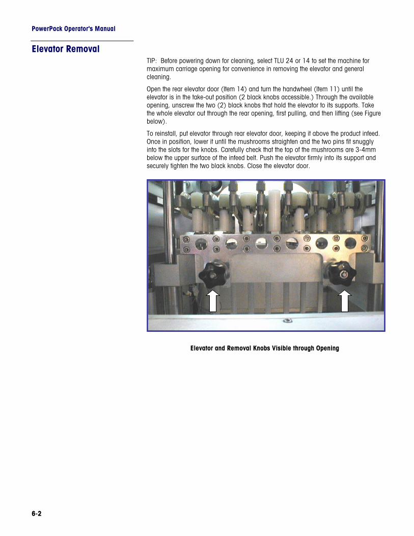
Elevator Removal TIP: Before powering down for cleaning, select TLU 24 or 14 to set the machine for maximum carriage opening for convenience in removing the elevator and general cleaning.
Open the rear elevator door (Item 14) and turn the handwheel (Item 11) until the elevator is in the take-out position (2 black knobs accessible.) Through the available opening, unscrew the two (2) black knobs that hold the elevator to its supports. Take the whole elevator out through the rear opening, first pulling, and then lifting (see Figure below).
To reinstall, put elevator through rear elevator door, keeping it above the product infeed. Once in position, lower it until the mushrooms straighten and the two pins fit snuggly into the slots for the knobs. Carefully check that the top of the mushrooms are 3-4mm below the upper surface of the infeed belt. Push the elevator firmly into its support and securely tighten the two black knobs. Close the elevator door.
Elevator and Removal Knobs Visible through Opening
Chapter 6: Cleaning and Maintenance Cleaning
6-3
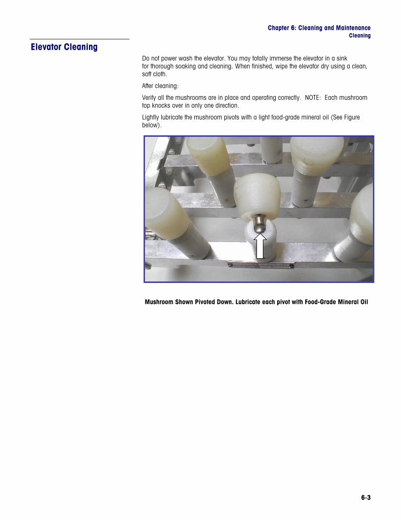
Elevator Cleaning Do not power wash the elevator. You may totally immerse the elevator in a sink for thorough soaking and cleaning. When finished, wipe the elevator dry using a clean, soft cloth.
After cleaning:
Verify all the mushrooms are in place and operating correctly. NOTE: Each mushroom top knocks over in only one direction.
Lightly lubricate the mushroom pivots with a light food-grade mineral oil (See Figure below).
Mushroom Shown Pivoted Down. Lubricate each pivot with Food-Grade Mineral Oil
PowerPack Operator's Manual
6-4
Lubrication Lubrication should be carried out by a trained, authorized service technician. Refer to the PowerPack® Service and Installation Manuals for complete details on lubrication. Using SAE 40 weight food grade mineral oil, lubricate as follows:
Weekly
• Ball joints; tie rods and ends • Universal joints; product infeed drive
Monthly
• Check oil level of main gearbox – see note below. • Refill, if necessary, with highest quality SHC 630. • Lubricate all chain drives.
Yearly
Inspect gearbox components for wear.
Components Requiring Grease
Weekly, use a food grade bearing grease, grease as follows:
• Film Feed Gears • Carriage Shaft • Ball bearings of the ejector, elevator, and folder rods/shafts
Note: Always wipe off excess lubricants prior to use.
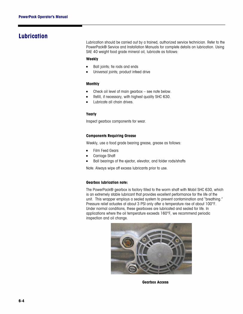
Gearbox lubrication note:
The PowerPack® gearbox is factory filled to the worm shaft with Mobil SHC 630, which is an extremely stable lubricant that provides excellent performance for the life of the unit. This wrapper employs a sealed system to prevent contamination and “breathing.” Pressure relief actuates at about 3 PSI only after a temperature rise of about 100°F. Under normal conditions, these gearboxes are lubricated and sealed for life. In applications where the oil temperature exceeds 160°F, we recommend periodic inspection and oil change.
Gearbox Access
Chapter 7: Printed Registered Film Option Film Types
7-1
7 Printed Registered Film Option
Film Types There are two distinct types of printed film available, printed (continuous pattern) film; and printed, registered film. Continuous print film needs no special parameters because it is not necessary to center the pattern on the package.
Printed Registered film, on the other hand, is designed to place a pattern in a set position on the package. For this reason, registration marks are printed on the film in the proper place for the registered film reading photocells to detect. The input from these marks is used to calculate film length and film positioning over the package so that a specific location for the printed design can be achieved and maintained.
It is critical that the film is laid out correctly. Contact Exact Equipment’s Engineering or Service Department for assistance.
Determining Film Width
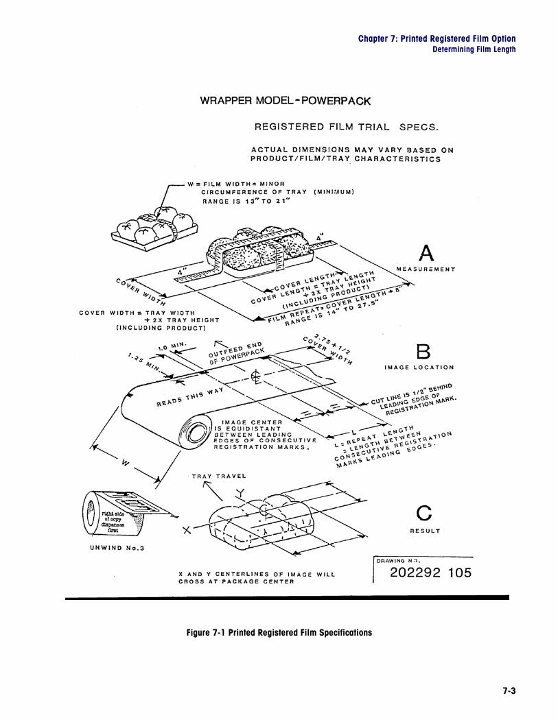
To determine the Film Width – Refer to Figure 7-1:
Measure the minor circumference of the tray, include product. Film width must be at least equal to the circumference, and no greater than the circumference plus the width (shorter dimension) of the tray bottom.
The vertical centerline of the printed image must be positioned 2.75 inches + 1/2 of the cover width from the rear edge of the film. The cover width is equal to the tray width plus twice the height of the tray, including product, as measured in “A” shown in Figure 7-1.
EXAMPLE
This will use a number 8 tray (8” wide) with product 2” high.
Film width is 8” + 8” + 2” + 2” = 20” minimum.
Cover width = 8” (tray width) + 2” x 2” = 12”.
Image centerline is 2.75” + 1/2 (12”) = 8.75” down from rear edge.

PowerPack Operator's Manual
7-2
Determining Film Length
To determine the film length required, measure tray cover length, which is equal to the tray length plus twice the height, including product, as shown in “A” in Figure 7-1. Film repeat length, or pitch, is equal to cover length + 8” for a typical tray. For the Number 8 tray, (8”W x 10”L), the typical repeat length would be approximately 10 + 2 + 2 + 8 = 22”.
The horizontal image centerline must be 1/2” offset from the center of the leading edges of the registration marks, as shown in “B and “C” in Figure 7-1.
The above should provide usable results. Variability of film, tray and product characteristics will result in some variance. Experiment first to determine optimum width and length before committing to large quantities of film purchase.
NOTES:
• Film is “unwind #3”. • Film image is erect and reads correctly from left to right when viewed from machine
infeed. See “B” in Figure 7-1. • Film registration marks must be opaque to infrared light. • The PowerPack® cuts the film 1/2” from the leading edge of the registration mark. • 6” film core is recommended for registered printed film.
Chapter 7: Printed Registered Film Option Determining Film Length
7-3
Figure 7-1 Printed Registered Film Specifications

PowerPack Operator's Manual
7-4
EXACT EQUIPMENT
For your notes
Chapter 8: Product Warranty Warranty Details
8-1
8 Product Warranty
Warranty Details METTLER TOLEO/EXACT EQUIPMENT warrants equipment and apparatus sold against defects in workmanship or materials for 180 days from date of shipment provided the equipment is installed and serviced by Exact Equipment or an authorized Exact Equipment Distributor.
This warranty does not apply to expendable parts, malfunctions caused by packaging supply failure, repair labor, conditions of misapplication, abuse, lack of misapplication, abuse, lack of maintenance, improper installation or abnormal environmental conditions.
THE PROVISIONS OF THIS EXPRESS WARRANTY CONSTITUTE THE ONLY AGREEMENT BETWEEN THE PARTIES RESPECTING THE SUBJECT MATTER HEREOF. THERE ARE NO WARRANTIES WHICH EXTEND BEYOND THE DESCRIPTION HEREIN, INCLUDING THE WARRANTIES OF MERCHANTABILITY AND FITNESS.
METTLER TOLEDO/EXACT EQUIPMENT shall in no way be liable for any losses, costs, forfeitures, or damages (including loss of profits; liabilities of the purchaser to its customers or third persons; liability of Exact Equipment to its customers, employees or other third persons; and all other special incidental or consequential damages) whether direct or indirect, and whether or not resulting from or contributed to by the default, negligence, whether in manufacture or design, or failure to warn on the part of Exact Equipment, its agents, employees and subcontractors, which might be claimed as a result of or use (with or without an active malfunction), or malfunction of the equipment or apparatus covered by this warranty, or as a result of the failure of Exact Equipment to comply with or conform to any application terms or condition of sale.
REMEDIES AND DAMAGES
If equipment or apparatus sold shall fail to conform to the contract of sale; including, but not limited to the warranty of Exact Equipment, purchaser’s sole and exclusive remedy shall be at the sole option of Exact Equipment to repair or replace any non-conforming equipment or apparatus or parts thereof.

PowerPack Operator's Manual
8-2
EXACT EQUIPMENT
For your notes


20 N. Pennsylvania Avenue Morrisville, PA 19067 Phone: 215-295-200 Fax: 215-295-2080 P/N: 17297300A METTLER TOLEDO® and EXACT EQUIPMENT are registered trademarks of Mettler-Toledo, Inc. ©2005 Mettler-Toledo, Inc.
Quality certification. Development, production, and auditing in accordance with ISO9001. Environmental management system in accordance with ISO14001. Worldwide service. Our dense service network, among the best in the world, ensures the maximum availability and lifespan of your product. Conformité Européene This label is your guarantee that our products conform to the latest guidelines. On the Internet. You can find important information about our products and services, as well as our company, quickly and easily at http://www.mt.com and at www.exactequipment.com .
www.mt.com
14001