automatic vickers case depth measurement - arnold horsch · automatic vickers case depth...
TRANSCRIPT

Automatic Vickers Case Depth Measurement Arnold Horsch 1 AHOTEC® e.K., Werkstoffprüftechnik, 42859 Remscheid, Germany
Full automatic Vicker measurement with image analysing systems, is one of the common used measurement systems since more then 20 years, for Case depth measurement of Carburizing – Nitriding – Surface hardening. One of the most discussed points is the reproducibility by existing systems and beetween different systems. On examples from Industrial users will be shown the challenge which is still happen on used systems and the main points which are happen for discussions. The examples will shown the difficulties which existing, if systems are working in the accepted accuracy range of existing standards. Also will discussed the challenge for the future increase of Automatic Hardness Test Systems.
1. HISTORY
The first fully automatic hardness test machines for case depth examination were prepared from the beginning of the 1980 years in Japan by the companies like Akashi (Fig. 1) and Matsuzawa. Beginning in 1988 Leco ® Instruments built the first on PC based semi-automatic hardness test machines (Fig. 2), these machines are manufactured in Europe in high quantities, this was the first successful commercially system.
From about 1990 the first well functioning fully automatic systems on PC based image analysis systems are available. These systems are running from various manufacturers. Modern systems like the ecoHARD® VA (Fig. 3) have been working reliably in various industrial applications.
Fig. 1: Automatic Vickers machine from Akashi / Japan
Fig. 2: Semi automatic Case Depth Measurement System from Leco® Instruments 1990
Fig. 3: Full automatic Case Depth Measurement System from
AHOTEC® e.K.,2001
The most common applications is the test of case depth measurements and welding:
• Carburizing depth = CHD (Fig. 4)
• Nitriding depth = NHD
• Surface hardness depth = SHD
• Welding tests (Fig. 5)

Fig. 4: CHD measurement on Gears,
with evaluation curve
Fig. 5: Welding Test, with evaluation curve
2. ACTUAL SITUATION OF AUTOMATIC VICKERS TEST
Actual are a lot of different full automatic Vickers systems on the market, all of them use different solutions for the evaluation of indentations. There is no standard which regulate the evaluation with image analysis systems. This sometimes leads to different results on the same samples
In the case of the most used application, automatic Vickers case depth measurement of Carburizing – Nitriding – Surface Hardening, are often discussions about the results. These discussions often lead to no clear result, cause considerable costs. There are no clear statements about the reproducibility / accuracy of automatic measurements with automatic Vickers systems, by the test procedure Vickers HV0,5 and HV1.
3. ISO STANDARD 6507, GENERAL RULES FOR EVALUATION
In the ISO Standard 6507, Part 2, the general rules for the evaluation of Vickers indentations are presented. This means for HV 0,5:
3.1 Accuracy of the optical measuring device
Resolution of the measuring device Repeatability of the measuring device Indentations < 0,040 mm 0,002 mm 0,004 mm Indentations > 0,040 mm 0,5 % of d 1 % of d
d = measured indentation diagonal
3.2 Maximum permissible deviation by HV 0,5
Maximum permissible deviation of the hardness testing machine in ± in % Hardness HV Method
50 100 150 200 250 300 350 400 450 500 600 700 800 900 1000 1500 HV 0,5 4 5 5 6 6 7 7 8 8 9 11
3.3 Repeatability of the testing machine
Repeatability of testing machine max.
ñ 1 ) HV 0,2 to < HV 5
Testblock value HV 0,2 to < HV 5 Testblock value HV
> 225 HV 0,04 ñ 350 600 750
28 48 60
1 ) ñ is the average of 5 diagonal measurements
This shows, that f.e. a Vickers value from 750 HV0,5 has a possible scattering from 694 up to 806 HV, this is a total range from 112 Vickers, by a possible repeatability from 60 HV in this range.
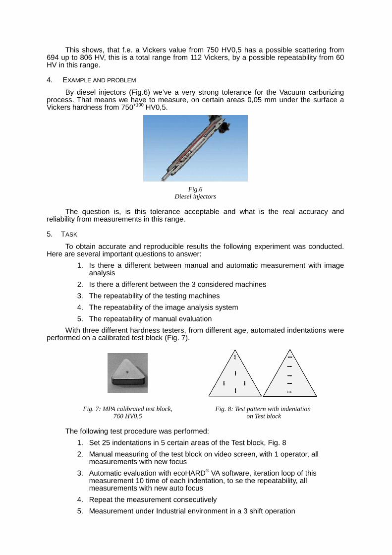
4. EXAMPLE AND PROBLEM
By diesel injectors (Fig.6) we’ve a very strong tolerance for the Vacuum carburizing process. That means we have to measure, on certain areas 0,05 mm under the surface a Vickers hardness from 750+100 HV0,5.
Fig.6 Diesel injectors
The question is, is this tolerance acceptable and what is the real accuracy and reliability from measurements in this range.
5. TASK
To obtain accurate and reproducible results the following experiment was conducted. Here are several important questions to answer:
1. Is there a different between manual and automatic measurement with image analysis
2. Is there a different between the 3 considered machines
3. The repeatability of the testing machines
4. The repeatability of the image analysis system
5. The repeatability of manual evaluation
With three different hardness testers, from different age, automated indentations were performed on a calibrated test block (Fig. 7).
Fig. 7: MPA calibrated test block, 760 HV0,5
Fig. 8: Test pattern with indentation on Test block
The following test procedure was performed:
1. Set 25 indentations in 5 certain areas of the Test block, Fig. 8
2. Manual measuring of the test block on video screen, with 1 operator, all measurements with new focus
3. Automatic evaluation with ecoHARD® VA software, iteration loop of this measurement 10 time of each indentation, to se the repeatability, all measurements with new auto focus
4. Repeat the measurement consecutively
5. Measurement under Industrial environment in a 3 shift operation

6. RESULTS
6.1 Different between manual measurement and measurement using image analysis
On one hardness testing machine automatically set hardness indentations were evaluated manually (Fig. 9 - 11) and automatically (Fig. 12 + 14), we analyzed the same hardness indentations. This experiment was repeated several times, always with same reproducible results. Measured on machine AHOTEC® ecoHARD® XV 1270 P
Fig. 9: manual evaluation Fig. 12:automatic evaluation
Fig. 10: manual evaluation Influence Software
average of the 25 indentations 10 times measured
Fig. 13: automatic evaluation Influence Software
average of the 25 indentations 10 times measured
Fig. 11: manual evaluation Influence Hardness Tester + Test Block
spread of 25 indentations, 10 times measured
Fig. 14: automatic evaluation Influence Hardness Tester + Test Block
spread of 25 indentations, 10 times measured
We see that the manual evaluation, a larger variation than the automatic analysis has. The difference is not huge but noticeable. Cause might be the problem of pixel resolution at higher magnifications with a camera, this leads to the manual evaluation of the measurement errors measuring lines.

6.2 Different between 3 machines
On 3 different machines we set 25 indentations on the same test block, on all three machines we set new indentations (Fig. 15-19).
Fig. 15: Future Tech LM 300, from 2001 Influence Software
average of the 25 indentations 10 times measured
Fig. 16: Future Tech LM 300, from 2001 Influence Hardness Tester + Test Block
spread of 25 indentations, 10 times measured
Fig. 17: Future Tech LM 700, from 2003 Influence Software
average of the 25 indentations 10 times measured
Fig. 18: Future Tech LM 700, from 2003 Influence Hardness Tester + Test Block
spread of 25 indentations, 10 times measured
Fig. 17: AHOTEC® ecoHARD® XV 1270 P, from 2008 Influence Software
average of the 25 indentations 10 times measured
Fig. 19: AHOTEC® ecoHARD® XV 1270 P, from 2008 Influence Hardness Tester + Test Block
spread of 25 indentations, 10 times measured
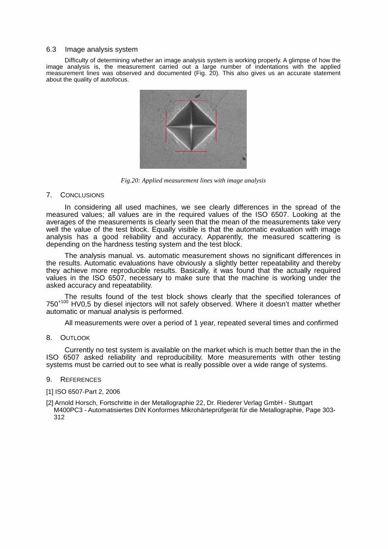
6.3 Image analysis system
Difficulty of determining whether an image analysis system is working properly. A glimpse of how the image analysis is, the measurement carried out a large number of indentations with the applied measurement lines was observed and documented (Fig. 20). This also gives us an accurate statement about the quality of autofocus.
Fig.20: Applied measurement lines with image analysis
7. CONCLUSIONS
In considering all used machines, we see clearly differences in the spread of the measured values; all values are in the required values of the ISO 6507. Looking at the averages of the measurements is clearly seen that the mean of the measurements take very well the value of the test block. Equally visible is that the automatic evaluation with image analysis has a good reliability and accuracy. Apparently, the measured scattering is depending on the hardness testing system and the test block.
The analysis manual. vs. automatic measurement shows no significant differences in the results. Automatic evaluations have obviously a slightly better repeatability and thereby they achieve more reproducible results. Basically, it was found that the actually required values in the ISO 6507, necessary to make sure that the machine is working under the asked accuracy and repeatability.
The results found of the test block shows clearly that the specified tolerances of 750+100 HV0,5 by diesel injectors will not safely observed. Where it doesn’t matter whether automatic or manual analysis is performed.
All measurements were over a period of 1 year, repeated several times and confirmed
8. OUTLOOK
Currently no test system is available on the market which is much better than the in the ISO 6507 asked reliability and reproducibility. More measurements with other testing systems must be carried out to see what is really possible over a wide range of systems.
9. REFERENCES
[1] ISO 6507-Part 2, 2006
[2] Arnold Horsch, Fortschritte in der Metallographie 22, Dr. Riederer Verlag GmbH - Stuttgart M400PC3 - Automatisiertes DIN Konformes Mikrohärteprüfgerät für die Metallographie, Page 303-312