automation and control ethernet tcp/ip and web technologies navigate
TRANSCRIPT

Automation and controlEthernet TCP/IP andWeb technologiesNavigate freely across auniversal networkCatalogue
October

Automation and controlMotion controlLexium 17D
05CatalogueApril
Automation and controlMotion controlLexium 17D
05CatalogueApril
Not all products shown in this catalogue are available in every country.Check individual country’s web site or Sales Office for product availability.See on: www.schneider-electric.com
AutomationDetection
!Global DetectionElectronic andelectromechanical sensorsN° 54752 - MKTED203031EN
Limit switchesProximity sensorsPhoto-electric and ultrasonicsensorsPressure switchesRotary encoders
SoftwareSafety mat configurationsoftware
!Modicon Momentumdistributed I/O and controlN° 807861 - MKTED205061EN
!Automation platformModicon Quantum andUnity - Concept ProworxsoftwareN° 802621 - MKTED204071EN
!Automation platformModicon Premium andUnity - PL7 softwareN° 802625 - MKTED204072EN
!Automation platformModicon TSX Micro andPL7 softwareN° 70984 - MKTED204012EN
PLCs, PC based controlDistributed I/OCommunication
!Automation and relayfunctionsN° 70455 - MKTED204011EN
Plug-in relaysElectronic timersControl relaysCountersSmart relays
SoftwarePLCs and safety controllersprogramming software
Operator dialog
!Control and signallingcomponentsN° 805911 - MKTED205021EN
Control and signalling unitsCam switchesBeacons and indicator banksControl and pendant stationsControllersFront panels, mounting kitsEmergency stopsFoot switches
!Human/Machine interfacesN° 96949 - MKTED2040401EN
Operator interface terminals,industrial PCs, Web servers,HMI and SCADA PC-basedsoftware
SoftwareOperator terminal software
Motor control
!Motor starter solutionsControl and protectioncomponentsN° 27501 - MKTED201001EN
ContactorsCircuit-breakers, fuse carriersThermal relaysCombinations, motorcontrollers
Mounting solutionsMotor starter mounting kits
!Soft starters and variablespeed drivesN° 802660- MKTED204091EN
Software,Variable speed drives
SoftwareMotor control programmingsoftware
Telemecanique,
catalogues for p p p p p p p p p p p p
Automation
N° 809201MKTED205102EN

Automation
Mounting systems
Detection
Interfaces & I/O
Networks & communication
Operator dialog Software tools
Motion control
Motor control
Power supply
Motion control
!Motion control Lexium 17DN° 806381 - MKTED205031EN
!Twin Line Motion controlN° 061233 -DIA7ED2030902EN
Servodrives and brushlessmotorsMotion control modulesModicon Premium andModicon Quantum
SoftwareSoftware for drives and motors
Power supplies
!Interfaces, I/O splitter boxesand power suppliesN° 70263 - MKTED203113EN
Switch mode power supplies
Filtered rectified powersupplies and transformers
Machine safety
This catalogue containsAutomation and Controlfunction products relating toSafety
!Safety solutions usingPreventaN° 67341 - MKTED203111EN
Safety monitors andcontrollers on AS-Interface
Switches, light curtains, mats
Emergency stops, controlstations, enabling switches,foot switches, beacons &indicator banks
Optimum and universalcontrollers
Switch disconnectors,thermal-magnetic motor circuitbreakers, enclosed D.O.L.starters
Interfaces & I/O
!Interfaces, I/O splitter boxesand power suppliesN° 70263 - MKTED203113EN
Plug-in relaysAnalog convertersDiscrete interfacesPre-wired interfacesIP67 Splitter boxes
ConnectorsCable ends, terminal blocks
!IP 20 distributed inputs/outputs Advantys STBN° 804818 - MKTED204101EN
Modules for automation islandNetwork interface,power distribution, digital I/O,analogs and application-specific
SoftwareSoftware to design and installAS-Interface system, safetymonitors and controllers onAS-Interface programmingsoftware
STB configuration software
AS-Interface
This catalogue containsAutomation and Controlfunction products relating tothe AS-Interface cablingsystem
!AS-Interface cabling systemN° 804961 - MKTED204121EN
IP20/IP67 interfaces, cables,repeaters, addressing andadjustment terminals
Control stations, keypads,beacons & indicator banks
Master modules for PLCs
AS-Interface power supplies
Motor controllers, enclosures,variable speed drives
Networks & communication
!Ethernet TCP/IP andWeb tecnologiesTransparent ReadyN° 809201 - MKTED205102EN
Embedded Web services
Ethernet communicationservices
Connecting Ethernet devices
Transparent Ready partners
!CANopenin machines & installationsN° 809xxx - MKTED205101EN
CANopen implementations
Telemecanique devices
Infrastructure, wiring system
CANopen partners
Simply Smart !
p p p p p p p p all Automation & Control functions

2
General contents 0 Transparent Ready
1 – PresentationIntroduction. . . . . . . . . . . . . . . . . . . . . . . . . . . . . . . . . . . . . . . . . . . . . . . . . page 1/2
Service classes offered . . . . . . . . . . . . . . . . . . . . . . . . . . . . . . . . . . . . . . . page 1/5
Panorama of Transparent Ready products . . . . . . . . . . . . . . . . . . . . . . .page 1/8
2 – System approachContents . . . . . . . . . . . . . . . . . . . . . . . . . . . . . . . . . . . . . . . . . . . . . . . . . . .page 2/1
Embedded Web services, FactoryCast offer . . . . . . . . . . . . . . . . . . . . . . page 2/2
Ethernet TCP/IP communication services . . . . . . . . . . . . . . . . . . . . . . . page 2/16
Performances of Ethernet TCP/IP network . . . . . . . . . . . . . . . . . . . . . . page 2/28
Industrial Ethernet cabling system. . . . . . . . . . . . . . . . . . . . . . . . . . . . . page 3/36
Application to specific domainsApplication to electrical distribution . . . . . . . . . . . . . . . . . . . . . . . . . . . page 2/42Application to Intelligent Motor Control Center (iMCC) . . . . . . . . . . . page 2/44Modicon Quantum Hot Standby . . . . . . . . . . . . . . . . . . . . . . . . . . . . . . page 2/46Application to Preventa Safety PLCs . . . . . . . . . . . . . . . . . . . . . . . . page 2/48
Integration of Transparent Ready products. . . . . . . . . . . . . . . . . . . . . . page 2/50
3 – Field devicesContents . . . . . . . . . . . . . . . . . . . . . . . . . . . . . . . . . . . . . . . . . . . . . . . . . . .page 3/1
Modicon Momentum distributed I/O . . . . . . . . . . . . . . . . . . . . . . . . . . . . . page 3/2
Advantys STB & OTB distributed I/O . . . . . . . . . . . . . . . . . . . . . . . . . . . . page 3/3
Lexium 17D servodrives for brushless motors . . . . . . . . . . . . . . . . . . page 3/5
ATV 61/71 variable speed drives . . . . . . . . . . . . . . . . . . . . . . . . . . . . . . . . page 3/6
Identification systems Inductel & Ositrack . . . . . . . . . . . . . . . . . . . . . . . page 3/8
4 – Ethernet gateway productsContents . . . . . . . . . . . . . . . . . . . . . . . . . . . . . . . . . . . . . . . . . . . . . . . . . . page 4/1
Ethernet/Modbus gateway . . . . . . . . . . . . . . . . . . . . . . . . . . . . . . . . . . . page 4/2
Web gateway, FactoryCast page 4/3
Ethernet/Modbus Plus gateway/router . . . . . . . . . . . . . . . . . . . . . . . . . page 4/4
5 – Electrical Distribution productsContents . . . . . . . . . . . . . . . . . . . . . . . . . . . . . . . . . . . . . . . . . . . . . . . . . . .page 5/1
MV / LV protection & metering andiMCC motors control-command . . . . . . . . . . . . . . . . . . . . . . . . . . . . . page 5/2
Advanced electrical circuit monitors . . . . . . . . . . . . . . . . . . . . . . . . . . . . page 5/4
Electrical power management software . . . . . . . . . . . . . . . . . . . . . . . . . page 5/5

3
6 – Controllers and PLCsContents . . . . . . . . . . . . . . . . . . . . . . . . . . . . . . . . . . . . . . . . . . . . . . . . . . page 6/1
Modicon Momentum M1E processor adapters. . . . . . . . . . . . . . . . . . . . page 6/2
Twido compact base controller . . . . . . . . . . . . . . . . . . . . . . . . . . . . . . . . page 6/3
TwidoPort interface for Twido controllers . . . . . . . . . . . . . . . . . . . . . . . page 6/4
Modicon TSX Micro platform . . . . . . . . . . . . . . . . . . . . . . . . . . . . . . . . . . page 6/5
Modicon Premium/Atrium platform . . . . . . . . . . . . . . . . . . . . . . . . . . . . . page 6/6
Modicon Quantum platform . . . . . . . . . . . . . . . . . . . . . . . . . . . . . . . . . . . page 6/9
Preventa safety PLCs . . . . . . . . . . . . . . . . . . . . . . . . . . . . . . . . . . . . . . . page 6/11
W@de Remote Terminal Units for the water sector . . . . . . . . . . . . . . page 6/13
7 – Human/Machine Interface productsContents . . . . . . . . . . . . . . . . . . . . . . . . . . . . . . . . . . . . . . . . . . . . . . . . . . . page 7/1
Magelis XBT graphic terminals . . . . . . . . . . . . . . . . . . . . . . . . . . . . . . . . page 7/2
Magelis iPC industrial PCs . . . . . . . . . . . . . . . . . . . . . . . . . . . . . . . . . . . . page 7/3
Web application development, FactoryCast HMI software . . . . . . . . . . page 7/5
Vijeo Look supervisory software . . . . . . . . . . . . . . . . . . . . . . . . . . . . . . . page 7/6
Monitor Pro supervisory software . . . . . . . . . . . . . . . . . . . . . . . . . . . . . . page 7/7
OFS data server software . . . . . . . . . . . . . . . . . . . . . . . . . . . . . . . . . . . . . page 7/8
8 – Cabling systemContents . . . . . . . . . . . . . . . . . . . . . . . . . . . . . . . . . . . . . . . . . . . . . . . . . . . page 8/1
ConneXium hubs . . . . . . . . . . . . . . . . . . . . . . . . . . . . . . . . . . . . . . . . . . . . page 8/2
ConneXium transceivers . . . . . . . . . . . . . . . . . . . . . . . . . . . . . . . . . . . . . page 8/3
ConneXium switches . . . . . . . . . . . . . . . . . . . . . . . . . . . . . . . . . . . . . . . . page 8/4
ConneXium connection cables . . . . . . . . . . . . . . . . . . . . . . . . . . . . . . . . page 8/7
9 – Modbus-IDA organisation andCollaborative Automation Partner ProgramContents . . . . . . . . . . . . . . . . . . . . . . . . . . . . . . . . . . . . . . . . . . . . . . . . . . . page 9/1
Modus-IDA organisation . . . . . . . . . . . . . . . . . . . . . . . . . . . . . . . . . . . . . . page 9/2
Collaborative Automation Partner Program . . . . . . . . . . . . . . . . . . . . . page 9/3
Transparent Ready Partners . . . . . . . . . . . . . . . . . . . . . . . . . . . . . . . . . . page 9/4
Index page 148

1/0
1

1/1
1
Contents 1 - Presentation 0
1 - Presentation
b Introduction . . . . . . . . . . . . . . . . . . . . . . . . . . . . . . . . . . . . . . . . . . . . . . . page 1/2
b Service classes offered . . . . . . . . . . . . . . . . . . . . . . . . . . . . . . . . . . . . . . page 1/5
Panorama of Transparent Ready products (field devices, gateways,
electrical distribution products, controllers and PLC, terminals) . . . . page 1/8
Selection guide of Ethernet gateways . . . . . . . . . . . . . . . . . . . . . . . . . page 1/10
Selection guide of HMI products . . . . . . . . . . . . . . . . . . . . . . . . . . . . . page 1/10
Selection guide of ConneXium cabling system . . . . . . . . . . . . . . . . . page 1/11

1/2
1
Presentation Transparent Ready 0
Universal technologies for a worldwithout restrictions
Company environments are constantly changing due to the pressure of competitionand the need for profitability. It is vital to take opportunities quickly. The challenge oftoday’s world is therefore agility, which means adopting a collaborative approachto share data in real-time.
Schneider Electric’s Transparent Ready products, based on universal EthernetTCP/IP and Web technologies, meet this requirement. These industrial automationproducts (Trademark Telemecanique) and Electrical Distribution products(Trademark Merlin Gerin) can be integrated into real-time data-sharing systems, withno need for interfaces.
PresentationTransparent Ready making collaborative architectures a reality
Network management Internet browser
Router

1/3
1
Presentation (continued) Transparent Ready 0
Universal technologies for a worldwithout restrictions
The recognition of Ethernet TCP/IP, both in organizations and on the Internet, hasmade it the communication standard of today. Its wide use is leading to a reductionin connection costs, increased performance and the addition of new functions, whichall combine to ensure its durability.
Ethernet TCP/IP meets the connection requirements of every application:b Twisted pair copper cables for simplicity and low cost.b Optical fiber for immunity to interference and for long distances.b Communication redundancy, inherent in the IP (Internet Protocol).b Radio or satellite to overcome wiring restrictions.b Remote point-to-point access via the telephone network or the Internet for the costof a local call.
Ethernet TCP/IP, a truly open technology, supports all types of communication:b Web pages.b File transfer.b Industrial messaging, etc.
With its high speed, the network no longer limits the performance of the application.The architecture can evolve without any difficulty. The products or devices remaincompatible, ensuring the long-term durability of the system.
Modbus has been the de facto standard for serial link protocols in industry since1979. It is used for the communication of millions of automation devices. As a resultof this success, the Internet community has reserved the TCP 502 port for Modbus.Modbus is recognised by international standard IEC 61158 and is a “ChineseNational Standard”.
Modbus messaging can thus be used for exchanging automation data on bothEthernet TCP/IP and the Internet, as well as for all other applications (file exchange,Web pages, E-mail, etc).The simple structure of Modbus is bringing it ever-increasing success. Users candownload the specifications and source code for numerous devices that use theModbus TCP/IP protocol, free of charge from the Modbus-IDA website:www.modbus-ida.org
Building on its industrial expertise, Schneider Electric now has a complete offer ofhighly user-friendly services on Ethernet TCP/IP that are dedicated to the world ofautomation: Modbus TCP/IP messaging, optimized I/O Scanning, publication andsubscription of variables between Controllers and PLCs (Global Data), automaticdevice reconfiguration (Faulty Device Replacement), bandwidth monitoring, systemdiagnostics par Web diagnostic, SOAP/XML Web services, etc.
The single network, requiring no interfaces between the worlds of informationtechnology and automation, is now a reality.
Presentation (continued)The universal communication standard: Ethernet TCP/IP
Modbus messaging: a standard technology adapted for the world of automation

1/4
1
Presentation (continued) Transparent Ready 0
Universal technologies for a worldwithout restrictions
In 1998, Schneider Electric broke new ground with the first on market Web serversembedded in Telemecanique PLCs.
With continuous innovations, Schneider Electric is spreading the use of Webtechnologies in industrial equipment by implementing Web servers inside newTelemecanique and Merlin Gerin devices such as PLCs and controllers, distributedI/Os, variable speed drives, power meters, etc.
These web servers represent the easiest solution to get remote and transparentaccess to equipment informations and device diagnostics, simply using an Internetbrowser.
With FactoryCast HMI, Schneider Electric is taking an important step further, bymaking the Web Servers “Active”, thus holding your HMI application as a Webserver.
Not only does these actice server provide Web pages displaying system and processinformation, but they also execute HMI functions at source in the PLC and controllerdevice, totally autonomously, without making use of the controller processor:management of a real-time HMI database with data processing, E-mail transmission,direct connectivity with relational databases, etc.
With its functions embedded in a controller, the FactoryCast HMI active Web server:b Simplifies or removes the need for conventional HMI/SCADA (Supervision ControlAnd Data Acquisition) solutions, reducing communication via polling to updateHMI/SCADA databasesb Provides multiclient remote control, without any special software on the clientstationsb Provides a direct link to company information systems, without the need for anyintermediary interface.
Schneider Electric has a wide range of Transparent Ready products: Controllers andPLCs, industrial PCs, HMI devices, variable speed drives, I/O modules, safety PLCs,gateways, servers, switches, SCADA software, inductive identification systems, etc.
These products provide different levels of Web services and communication serviceson Ethernet TCP/IP, according to users’ requirements. In order to simplify choice andensure their interoperability within a system, each Transparent Ready product is nowidentified by the class of services it provides.
b Ingenuity of collaboration improving agilityv Transparency of information throughout the enterprise, make authorized peopleand tools, better share data.
b Openess of universal standards Ethernet TCP/IP with Modbusv Vendor independent and well known, so future proof and openv Only one commubication technology to maintainv Seamless vertical & remote connections, enabling collaboration.
b Simplicity of Web technologies optimizing your Human Machine Interfacev Easy and inexpensive local & remote access from a web browser (e.g. formaintenance)v Distribute Web servers on automation devices and remove bottlenecksv Combine Web technologies and traditional SCADA, to refocus SCADA on thecontrol of the process.
Presentation (continued)Free navigation on the Web Automation
Transparent Ready for a world without restrictions
WithTransparent Ready, you have ...

1/5
1
Description Transparent Ready 0
Service classes offered
The Transparent Ready service classes make it possible to identify the servicesprovided by each device:b Diagnostic, display and control services via Web technologiesb Ethernet communication services.
The Transparent Ready service classes thus simplify the choice of devices andensure their interoperability within an architecture.
The Web services are defined by 4 classes identified by a letter:b Class A: No Web serviceb Class B: Standard Web servicesb Class C: Configurable Web servicesb Class D: Active Web services.
Transparent Ready devices with an embedded Web server can provide 4 types ofWeb service:b Maintenance Web servicesb Control Web servicesb Diagnostic Web servicesb Optional Web services such as documentation or configuration.
The following table specifies the services provided by each Web service class (A, B,C or D).
Presentation
Transparent Ready
Ethernet TCP/IPtechnologies and
services
Web technologiesand services
Web service classes
Web server class
Maintenance Monitoring and IT link Diagnostics Optional
Web services
ActiveWeb server
ConfigurableWeb server
StandardWeb server
No Webserver
D
C
B
A
- User website update
- Remote device softwareupdate- Remote auto-tests
- Device description- Data viewer
- No Web service
- Autonomous execution ofspecific services (e.g. alarmnotification by E-mail,exchange with databases,calculations, ...)- SOAP/XML (client/server)
- PLC variables editor- Remote commands- User Web pages- SOAP/XML (server)
- User-defined states
- Communication servicediagnostics- State of internal deviceresources
- Device status- Device diagnostic
- User documentation
- Configuration of networkparameters and Ethernetcommunication services- Device documentation

1/6
1
Description (continued) Transparent Ready 0
Service classes offered
The Ethernet communication services provided by a device are defined by 3 classes,identified by a number:b Class 10: standard Ethernet communication servicesb Class 20: Ethernet communication management services (network level anddevice level)b Class 30: advanced Ethernet communication services.
Transparent Ready devices can provide eight types of Ethernet communicationservice:b Modbus TCP/IP messaging serviceb I/O Scanning serviceb FDR (Faulty Device Replacement) serviceb SNMP network management serviceb Global Data serviceb Bandwidth management serviceb NTP time synchronization serviceb SMTP event notification service (E-mail).
These Ethernet communication services are described in chapter 2, “Systemapproach”, see pages 2/16 to 2/27.
The following table specifies the services provided for each Ethernet communicationservice class.
Ethernet communication service classes
Ethernetcommunicationservice classes
30
20
10
Ethernet communication services
Modbusmessaging
I/OScanning
FDR Networkmanagement
SNMP
GlobalData
Bandwidthmanagement
Timesynchroni-zation NTP
Advancedservices
Communicationmanagementservices
Standardservices
- Directreading/writingof I/O
- Periodicreading/writingof I/O
- Configurationof the list ofdevicesscanned
- Use of theMIB library byan SNMPmanager
- Automaticcontrol andupdating of thedeviceparametersconfiguration
- Automaticassignment ofthe IP addressand networkparameters- Control andupdating of theconfigurationand deviceparameters bythe user
- Localassignment ofthe IP addressVerification ofduplicate IPaddresses
- Monitoring ofload level
-Synchroniza-tion of deviceclocks
- Publicationandsubscriptionof networkvariables
- Reading/writing of datawords
- Detection ofdevices by anSNMPmanager
E-mailSMTP
- Notificationof events byE-mail

1/7
1
Description (continued) Transparent Ready 0
Service classes offered
The services provided by a Transparent Ready device are identified by a letterdefining the level of Web service, followed by a number defining the level of Ethernetcommunication service. For example:b A class A10 product is a device with no Web service and standard Ethernetservicesb A class C30 product is a device with a configurable Web server and advancedEthernet communication services.
The services provided by a higher class include all the services supported bya lower class.
Transparent Ready devices are chosen from 4 main families:b Sensor and preactuator type field devices (simple or intelligent)b Controllers and PLCsb Human Machine Interface (HMI) applicationsb Dedicated gateways and servers.
The selection table on the following pages can be used for choosingTransparent Ready devices according to the required service classes.
Choice of Transparent Ready devices
Class 30
Simple and intelligent devices
Class A Class B Class C Class D
A10
B20
B30
Class 20Controllers and PLCs
D10
C20
Class 10
Sta
ndar
dse
rvic
esC
omm
unic
atio
nm
anag
emen
tse
rvic
es
Adv
ance
dse
rvic
e
B10
No service Standard Configurable Active
Web services
Ethernetcommunication
services

1/8
1
Selection Transparent Ready 0
Product selection
Ethernet TCP/IP communicationservices
Web services No Web serviceClass ANo Web service
Advanced servicesClass 30
v FDR (faulty devicereplacement),automatic checking ofnetwork parameters
v SNMP (networkadministration), use ofthe MIB library by anSNMP tool
v Global Datav Bandwidth
managementv NTP (clock
synchronization)v SMTP (notification by
E-mail)
CommunicationmanagementservicesClass 20
v Modbus TCP/IPmessaging (read/writeI/O)
v I/O Scanningv FDR (faulty device
replacement),automatic assignmentof network parameters
v SNMP (networkadministration),product detection
StandardcommunicationservicesClass 10
v Modbus TCP/IPmessaging
v FDR (faulty devicereplacement),verification of duplicateIP address
Momentum adapter 170 ENT 110 02Advantys OTB interface OTB 1E0 DM9LPOsitrack identification system XGK Z33ETHTwido compact base TWD LCAE 40DRFTwidoPort interface 499 TWD 01100Atrium coprocessor TSX PCI 57 204/454MPreventa safety compact PLC XPS MF 30/31/35Preventa safety modular PLC XPS MF 60Modbus gateway 174 CEV 300 20Modbus Plus gateway 174 CEV 200 40Magelis graphic terminal XBT G/XBT GTMagelis graphic terminal XBT F024/034Magelis Smart & Compact iPC MPC ST5/KT5Magelis Modular iPC MPC AN0/BN0/CN0
TSX ETY TSX P57
140 NOE 140 CPU
TSX ETZTSX ETG 1010
170 ENT
STB NIP
TSX ETG 1000ATV 71/61
TWD LCAE
170 ENTOTB 1E0
TSX PCI
EGX 400MG
XGKS499 TWD
EGX 100MGSmart iPC
XBT G

1/9
1
0
See page
Standard Web servicesClass B
Configurable Web servicesClass C
Active Web servicesClass D
v View device description and statusv Remote software update
v Variables editorv Remote commandsv User Web pagesv Communication service diagnosticsv SOAP/XML server
v Autonomous execution of servicesv Diagnostics of user-defined statesv Alarm notification by E-mailv Databases accessv SOAP/XML client/server
Premium module TSX ETY 4103 Premium FactoryCast module TSX ETY 5103 6/8Premium processor TSX P57 1634MPremium processor TSX P57 2623/34MPremium processor TSX P57 2823Premium processor TSX P57 3623/34MPremium processor TSX P57 4823Premium processor TSX P57 4634/5634M
6/6
Quantum module 140 NOE 771 01 Quantum FactoryCast module 140 NOE 771 11 6/10Quantum processor 140 CPU 65150Quantum processor 140 CPU 65160
6/9
TSX Micro module TSX ETZ 410 TSX Micro FactoryCast module TSX ETZ 510 6/5Momentum adapter 170 ENT 110 01 3/2
Advantys STB module STB NIP 2212 3/6 & 3/7Altivar 71/61 communication card VW3 A3 310 3/5Modbus FactoryCast Gateway TSX ETG 1000 4/3
Uni-Telway FactoryCast GatewayTSX ETG 1010
4/3
Premium FactoryCast module TSX ETY 110 WS Premium FactoryCast HMI TSX WMY 100 6/8Quantum FactoryCast HMI 140 NWM 100 00 6/10
W@de remote terminal unit for water W330 6/133/23/4
3/96/36/4
6/76/117/12
4/44/47/2
7/27/37/4
Inductel identification station XGK S1715503 3/8Lexium 17D communication cardAM0 ETH 00p V000
3/7
Modbus gateway EGX 100MG (1) 5/2Modbus gateway TSX ETG 100 4/2
Momentum M1E 171 CCC 980 p0Momentum M1E 171 CCC 960 p0
6/2
W@de remote terminal unit for waterW315/W320
6/13
Modbus server EGX 400MG (1) 5/3Circuit Monitor card ECC 21 5/4
(1) Dedicated to Sepam protection relays, to Micrologic protection units for Masterpact circuit-breakers, to Power Logic PM et CM power meters.

1/10
1
Selection guide Transparent Ready 0
Ethernet gateways of Schneider ElectricHuman-Machine Interface productsConneXium cabling system
Gateways
Converter
Transparent Ready class A10 B20 C20 C10
Dedicated to Twido controller TSX Micro automation platform CM 3000/4000 circuitmonitor
Communication type Many-to-one Modbusserial link
Many-to-one terminal port (Uni-TE) Many-to-one Modbusserial link
Embedded Web server – Standard FactoryCastconfigurable
WPG type
Remote acces – Remote Access Server (RAS) –
Type of gateway 499 TWD 01100 TSX ETZ 410 TSX ETZ 510 ECC21
Page 6/4 6/5 5/4
Human-Machine Interface products Graphic terminals Industrial PCs Web HMIapplicationdevelopmentsoftware
SCADAsupervisorysoftware
Transparent Ready class A10 –
Display 3.8”, 5.7”, 7.4”, 10.4”,12.1”
12”, 15” –
Type of HMI products Magelis XBT G/GTMagelis XBT F
Magelis iPC FactoryCast HMI Vijeo LookMonitor ProOFS
Pages 7/2 7/3 and 7/4 7/5 7/6 to 7/8

1/11
1
0
r Available later
Router Server
B10 C10 D10
Automation andcontrol
Automation andcontrol
Electricaldistribution (hightemperaturerange)
Remote terminalunit for waterdomain apllication
Automation and control Electricaldistribution
Remote terminalunit for waterdomain apllication
Many-to-manyModbus Plusnetwork
Many-to-many Modbus serial link Many-to-manyModbus serial link
Many-to-manyUni-Telway seriallink
Many-to-many Modbus serial link Many-to-manyModbus serial linkUni-Telway seriallink
– PowerLogic -RNIM (SyMax)
– Standard FactoryCast configurable WPG type Configurable
– GSM/GPRS,PSTN,Leased Line orradio modem
Remote Access Server – GSM/GPRS,PSTN,Leased Line orradio modem
174 CEV 200 40 TSX ETG 100174 CEV 300 20
EGX 100MG TSX ETW 315 rTSX ETW 320 r
TSX ETG 1010 TSX ETG 1000 EGX 400MG TSX ETW 330
4/4 4/2 et 4/4 5/2 6/14 4/3 5/3 6/13
r
ConneXium cabling system Hubs Transceivers SwitchesIP 20/IP 30 IP 67
Type of ports Copper cable and/or optical fiber Copper cable
Selection guidelines See page 8/2 to 8/7
Type 499 NEH/NOH 499 NTR 499 NES/NOS/NMS/NSS TCS ESU
Pages 8/2 8/3 8/4 and 8/5 8/6

2/0
2
Contents 2 - System approach 0
2.1 Embedded Web servicesb FactoryCast overview . . . . . . . . . . . . . . . . . . . . . . . . . . . . . . . . . . . . . . . page 2/2
b Standard Web services . . . . . . . . . . . . . . . . . . . . . . . . . . . . . . . . . . . . . . page 2/2
b FactoryCast configurable Web services . . . . . . . . . . . . . . . . . . . . . . . . . page 2/4
b FactoryCast HMI active Web services . . . . . . . . . . . . . . . . . . . . . . . . . . . page 2/8
b FactoryCast Gateways Web services. . . . . . . . . . . . . . . . . . . . . . . . . . page 2/12
b SOAP/XML Web services . . . . . . . . . . . . . . . . . . . . . . . . . . . . . . . . . . . page 2/14
2.2 Ethernet TCP/IP communication servicesb Standard Ethernet services . . . . . . . . . . . . . . . . . . . . . . . . . . . . . . . . . . page 2/16
b Modbus communication standard . . . . . . . . . . . . . . . . . . . . . . . . . . . . . page 2/19
b I/O Scanning service . . . . . . . . . . . . . . . . . . . . . . . . . . . . . . . . . . . . . . . page 2/20
b FDR replacement service for faulty devices . . . . . . . . . . . . . . . . . . . . . page 2/21
b Global Data service in real time between stations . . . . . . . . . . . . . . . . . page 2/22
b NTP time synchronization service . . . . . . . . . . . . . . . . . . . . . . . . . . . . . page 2/23
b SMTP electronic mail notification service . . . . . . . . . . . . . . . . . . . . . . . page 2/24
b SNMP network management protocol service . . . . . . . . . . . . . . . . . . . . page 2/25
b TCP Open optional service . . . . . . . . . . . . . . . . . . . . . . . . . . . . . . . . . . page 2/26
2.3 Performance of Ethernet TCP/IP networkb Guidelines to evaluate the network load . . . . . . . . . . . . . . . . . . . . . . . . page 2/28
b Application response time . . . . . . . . . . . . . . . . . . . . . . . . . . . . . . . . . . . page 2/32
b Processing capabilities of Premium and Quantum PLCs . . . . . . . . . . page 2/34
2.4 Industrial Ethernet cabling systemb Ethernet 802.3 principles . . . . . . . . . . . . . . . . . . . . . . . . . . . . . . . . . . . . page 2/36
b Different network topologies . . . . . . . . . . . . . . . . . . . . . . . . . . . . . . . . . page 2/37
b Distance limits and number of devices per segment . . . . . . . . . . . . . . . page 2/38
b Physical media . . . . . . . . . . . . . . . . . . . . . . . . . . . . . . . . . . . . . . . . . . . page 2/39
b Redundancy . . . . . . . . . . . . . . . . . . . . . . . . . . . . . . . . . . . . . . . . . . . . . page 2/40
b Guidelines to select cabling industrial devices . . . . . . . . . . . . . . . . . . page 2/41

2/1
2
0
2.5 Application to specific domainsb Electrical distribution . . . . . . . . . . . . . . . . . . . . . . . . . . . . . . . . . . . . . . . page 2/42
b Intelligent Motor Control Center (iMCC) . . . . . . . . . . . . . . . . . . . . . . . . page 2/44
b Modicon Quantum Hot Standby on Ethernet TCP/IP . . . . . . . . . . . . . . page 2/46
b Preventa safety PLCs . . . . . . . . . . . . . . . . . . . . . . . . . . . . . . . . . . . . . . page 2/48
2.6 Integration of Transparent Ready productsb Company level . . . . . . . . . . . . . . . . . . . . . . . . . . . . . . . . . . . . . . . . . . . page 2/50
b Inter-PLC level . . . . . . . . . . . . . . . . . . . . . . . . . . . . . . . . . . . . . . . . . . . page 2/51
b Field level
v Communication with field products Modbus . . . . . . . . . . . . . . . . . . . page 2/52
v Communication with CANopen in machines and installations . . . . . page 2/53
v Communication between field PCs or operator terminals, PLCs and field
devices . . . . . . . . . . . . . . . . . . . . . . . . . . . . . . . . . . . . . . . . . . . . . . . page 2/53
b Transparent remote communication
v On the Internet . . . . . . . . . . . . . . . . . . . . . . . . . . . . . . . . . . . . . . . . . page 2/54
v Via telephone networks . . . . . . . . . . . . . . . . . . . . . . . . . . . . . . . . . . page 2/55
v By radio . . . . . . . . . . . . . . . . . . . . . . . . . . . . . . . . . . . . . . . . . . . . . . . page 2/55
b Other requirements (diagnostic, interoperability, security)
v Diagnostics services . . . . . . . . . . . . . . . . . . . . . . . . . . . . . . . . . . . . . page 2/56
v Interoperability with third-party products or protocols . . . . . . . . . . . . page 2/56
v Ethernet TCP/IP network security . . . . . . . . . . . . . . . . . . . . . . . . . . . page 2/57

2/2
2
2.1
Presentation Transparent Ready 0
System approachStandard and FactoryCast Web services
Schneider Electric offers a wide range of Transparent Ready products integratingWeb services: controllers and PLCs, safety PLCs, industrial PCs, HMI devices (2),variable speed drives, distributed I/O modules, gateways, switches, inductiveidentification systems, etc.
These products provide different levels of Web services and communication serviceson Ethernet TCP/IP, according to user requirements.
Among these Transparent Ready products, FactoryCast defines a range of modulesand gateways with configurable Web server combining:b Real-time communication functions based on Ethernet TCP/IPb Predefined Web pages for advanced installation diagnosticsb And the capacity to host dynamic user-defined Web pages or any document (.doc,pdf, etc) designed to assist maintenance.
In the Transparent Ready approach, Ethernet modules and gateways integrateEthernet TCP/IP services (Modbus TCP/IP messaging, SNMP network managementfunctions, etc).They also offer, depending on the product, the following Web functions:b Standard Web services (predefined)b FactoryCast configurable Web servicesb FactoryCast HMI active Web services.
There are two ranges of configurable Web server:b FactoryCast modules with TSX Micro, Premium, Quantum, Momentumautomation platforms. These modules provide transparent access to system andapplication diagnostic information in real-time using Web technologiesb FactoryCast Gateway that integrate all the network interfaces, a router RASfunction and a customizable Web server in a stand alone unit.The FactoryCast Gateway is a cost-effective response to the need to integrate serialinstallations (Modbus or Uni-Telway) in an existing Ethernet TCP/IP infrastructure,as well as requirements for customized remote access services including remotediagnostics, maintenance, monitoring and control using a simple Web browser.
Standard Web services are integrated in the following Schneider Electric Ethernetproducts: PLC processors and Ethernet modules, distributed I/O modules, variablespeed drives, Ethernet gateways. See selection guide page 2/3.Using a simple Web browser, the standard Web services provide the following“ready-to-use”:b Device configuration setupb Remote device diagnostic and maintenanceb Device data monitoring (read/write variables ans status).
The embedded Web server is a real-time data server. All the data are presented inthe form of standard Web pages in HTML format and can therefore be accessedusing any Web browser supports the embedded JAVA code. The standard functionsprovided by the Web server are supplied “ready to use” and therefore do not requireany programming of either the PLC or device or the client PC supporting the Webbrowser.
(1) In order to simplify choice and ensure their interoperability within a system, each TransparentReady product is identified by the class of services it provides. Letter A, B, C or D (level ofservice for the Web server) followed by 10, 20 or 30 (level of service for Ethernetcommunication). See pages 1/5 to 1/7.
(2) HMI = Human Machine Interface.
Web services overviewDatabase Connectivity
E-mail notification
HMI functions
User defined Web pages
Graphic data monitoring
Application diagnostic
Data monitoring
Device diagnostic
Device configuration
Standard Web serverClass B (1)
Configurable Web serverClass C (1)
Active Web serverClass D (1)
Web services embedded in Ethernet modules and gateways
Web services presentationStandard Web services

2/3
2
2.1
Presentation (continued),product selection
Transparent Ready 0
System approachStandard and FactoryCast Web services
FactoryCast configurable Web services are integrated in the following SchneiderElectric Ethernet products: TSX Micro, Premium and Quantum FactoryCast PLCsmodules and FactoryCast Gateway modules.
In addition to the predefined Web services, the configurable Web server offers thefollowing utilities:b Graphic application diagnostics (customized graphic views created by the user)b Graphic monitoring via animated Web pages created by the user and stored in theWeb server module.And depending on the products:b Management of controllers system and application alarms, with partial or totalacknowledgement (“ready-to-use” “Alarm Viewer” pages)b SOAP/XML server interface (1).
FactoryCast Web services can also be used to customize supervision, diagnosticsand maintenance interfaces via user-defined Web pages or any other document(doc, pdf, etc) transferred to the module.
FactoryCast active Web services are integrated in the Premium and QuantumFactoryCast HMI PLC modules.
The FactoryCast HMI services provide in addition HMI functions, which are executedin the module itself:b Data acquisition with real-time HMI database management, independent of thePLC processorb Data processing (arithmetic and logical calculations)b Direct connectivity with relational databases (traceability, data login)b Recipe management (read/write)b Alarm and report notification by E-mailb Active page server, dynamic generation of animated HTML pagesb SOAP/XML client/server interface(1).
FactoryCast HMI is defined as an active Web server used to execute HMI functionswithout any effect on the PLC application program and therefore on its scan time.
(1) Standard protocol providing interoperability with computer management applications (seepage 2/14.
Presentation of the Web services (continued)
FactoryCast configurable Web services
FactoryCast HMI active Web services
Selection of Telemecanique brand Transparent Ready modulesProduct Reference Embedded Web server
Standard, class B10/B20 Configurable, class C20/C30 Active, class D10ModiconQuantum platform
Processors 140 CPU 651 50/60 –Modules 140 NOE 771 01 –
140 NOE 771 11 FactoryCast –140 NWM 100 00 FactoryCast HMI
ModiconPremium platform
Processors TSX P57 2p23 M – –
TSX P57 3623 M – –TSX P57 4823 M – –TSX P57 p634 M – –
Modules TSX ETY 4103 – –TSX ETY 110WS FactoryCast –TSX ETY 5103 FactoryCast –
TSX WMY 100 FactoryCast HMIModiconTSX Micro platform
Modules TSX ETZ 410 – –TSX ETZ 510 FactoryCast –
ModiconMomentum platform
M1Eprocessors
171 CCC 960 20/30 – –171 CCC 980 20/30 – –
Modules 171 ENT 110 01/02 – –
Advantys STBdistributed I/O
Networkinterface
STB NIP 2212 – –
Altivar ATV 71/61variable speed drives
Communicationcard
VW3 A3 310 –
Inductel identification station XGK S1715503 – –FactoryCast Web Gateway TSX ETG 1000/1010 FactoryCast –Remote terminal units W@de TSX ETW 315/320p1 – –
TSX ETW 330p1

2/4
2
2.1
Functions Transparent Ready 0
System approachPLC standard Web services
The predefined diagnostic, “PLC rack viewer”, and monitoring, “Data Editor”,functions are supported by the following Modicon PLC plateforms (1):b TSX Micro platformb Premium platformb Quantum platform.See module references on page 2/3.
These functions can be accessed using a standard Internet browser. They are “readyto use” and secured (password-protected).
They can be used locally or remotely via:b Intranetb A modem and RAS serverb Internet.
(1) For standard Web services integrated in the varaible speed drives, please consult ourcatalogue “Soft starters and variable speed drives”.
PLC standard Web services
Internet
Firewall
Intranet
Remote Web clients
"Thin Client" PCWeb client
"Thin Client"Web client
MagelisSmart iPC
Web server
Webserver
Webserver
QuantumPremium TSX Micro

2/5
2
2.1
Functions (continued) Transparent Ready 0
System approachEmbedded Web servers, standard Web services
The “Rack Viewer” function (PLC rack display) can be used for PLC system and I/Odiagnostics. It displays the following in real-time:b LED status on the front panel of the PLCb The PLC versionb The hardware configuration of the PLC including the status of the system bits andwordsb Detailed diagnostics of all I/O module channels or application-specific channels inthe configuration.
The “Data Editor” can be used to create animated tables for real-time read/writeaccess to lists of PLC variables.
Various animation tables can be created by the user and saved in the Web servermodule.
In addition when using FactoryCast Web servers:bThe variables can be entered and displayed by theirsymbol (S_Pump 234)bThe write access option can be enable/desable foreach variable using the Factorycast software. Thewrite access is protected by a dedicated passwordbDedicated data monitoring tool can be use onpocket PC or PDA terminal.
PLC standard Web services (continued)
PLC diagnostics function “Rack Viewer”
Quantum hardware configuration
Data monitoring function “Data Editor”

2/6
2
2.1
Functions 0 Transparent Ready 0
System approachFactoryCast configurable PLC Web services
“Alarm Viewer” is a ready-to-use, password-protected function. This function is usedto manage the alarms (display, acknowledgment and deletion) generated at PLClevel by the system or using diagnostic function blocks known as DFBs(system-specific diagnostic function blocks and application-specific diagnosticfunction blocks created by the user).
These alarms are store in the PLC diagnostic buffer (specific memory area used tostore all diagnostic events), this function is available with the Premium/Atriumplatforms (with PL7 or Unity Pro software) and the Quantum platform (with Unity Prosoftware).
The diagnostics viewer consists in a Web page displaying a list of messages, withthe following informations:b Time stamping of the appearence/disappearence of the faul.b Alarm messageb Alarm statusb Type of associated diagnostic function block (DFB).
This function is used to create graphical views animated by PLC variables. Thisgraphic editor is available online “ready-to-use” and also offline using FactoryCastconfigurator software.
These views are created by simple copy/paste operations, using a library ofpredefined graphic objects. The object parameters are set according to userrequirements (colors, PLC variables, labels, etc.).
List of graphic objects provided:b Analog and digital indicatorsb Horizontal and vertical bar chartsb Dialog boxes for displaying messages and controling/displaying valuesb Pushbuttonsb Trending chartsb Tanks, valves, motors, etc.
Many views created can be saved in the Web server modules.
These customized graphic objects can be reused in user defined Web pages thathave been created using standard software for editing HTML pages.
FactoryCast configurable PLC Web servicesIn addition to standard Web services, FactoryCastmodules (see selection table on page 2/3) support thefollowing functions:b Alarm Viewerb Creation and display of graphical views via an onlinegraphic editor (Graphic Data Editor integrated)b Hosting and display of user defined Web pagescreated by the userb SOAP/XML server interface.
Alarm Viewer function
Intranet
Internet
Remote Web client
Firewall
Premium
Quantum
Modem+RAS server Magelis
Smart iPC
TSX Micro
“Thin Client”Web client
Webserver
Webserver
Web server
Graphic Data Editor function

2/7
2
2.1
Functions (continued) 0 Transparent Ready 0
System approachFactoryCast configurable PLC Web services
FactoryCast Web modules also have an 8 Mbyte memory (1), which is accessed inthe same way as a hard drive and can be used to host Web pages and alluser-defined documents in Word or Acrobat Reader (for example, maintenancemanuals, diagrams, etc).These Web pages can be created using any standard tool, for example MicrosoftFrontPage, that enables creation and editing in HTML format. These pages can beenhanced by inserting animated graphic objects linked to PLC variables. Theseanimated objects are created using the Graphic Data Editor supplied withFactoryCast.
The Web pages created can be used, for example, to:b Display and modify all PLC variables in real timeb Create hyperlinks to other external Web servers (documentation, suppliers, etc).
This function is particularly suitable for creating graphic screens used for thefollowing purposes:b Display, monitoring, diagnosticsb Generation of realtime production reportsb Maintenance helpb Operator guides.
FactoryCast modules incorporate a standard SOAP/XML data server that providesdirect interoperability between automation devices and computer managementapplications (MES, ERP, SAP, pNet application, etc). See page 2/14.
(1) Memory not affected by power outages or reinitialization of the PLC.(2) FactoryCast includes a plug-in for FrontPage 2000. This plug-in makes it easier to set up
animations for realtime access to the PLC variables in HTML pages created by the user. Theyare created in the HTML editor by simply inserting customized graphic objects.
FactoryCast configurable PLC Web server (continued)
User Web page hosting and display function
SOAP/XML server interface
FactoryCast Web server configuration softwareThe FactoryCast Web server configuration software is supplied on CD-ROM with everyFactoryCast module (TSX ETZ 510 for TSX Micro, TSX ETY 110WS/5103 forPremium, 140 NOE 771 11 for Quantum and TSX ETG 1000/1010 gateways).This software is used for configuration and administration of the Web serverembedded in these modules. It is compatible with Windows 2000 and Windows XPoperating systems. It provides the following functions:b Setting the parameters of the FactoryCast functionsv Definition of access security, passwordsv Importing of PLC symbol databasesv Definition of access to write-enabled variablesb Management of the Web site:v Management of default Web site pagesv Management of user Web site pages (2)v Graphic object editor for animating Web pagesv Downloading of Web pages between the PC and the modulev Debugging of Web pages in online mode or in simulation mode (includinganimations and Java beans)b Simulation modeThe application and the Web site (including the Java animations) can be set up inonline mode or in simulation mode. Simulation mode is used to test the operation ofthe Web application without a FactoryCast module (with no physical connection to aPLC) thereby simplifying debugging.A graphics editor integrated in the configuration software can be used for easycustomization of graphic objects (bar charts, gauges, LEDs, curves, cursors,operator input fields, alphanumeric display fields, buttons, etc).b Creation of user Web pages (2)User Web pages are created graphically using an external HTML editor (FrontPageor similar, not supplied).User Web pages created in the FactoryCast environment are actual animatedsupervision screens and can be used to monitor your process. Based on Webtechnologies (HTML and Java) they provide realtime access to PLC variables usingthe FactoryCast graphic object library (Java beans).

2/8
2
2.1
Presentation Transparent Ready 0
System approachEmbedded Web services,FactoryCast HMI active Web services
The FactoryCast HMI Web services are integrated in PLC Web servers modules onPremium and Quantum PLC platforms.
These modules have the following Ethernet and Web services:b Ethernet TCP/IP communication functions:v TCP/IP messaging service with Modbus TCP/IP and Uni-TE TCP/IP protocolsv SNMP agent for standardized network management, which supports standardMIB II and private Transparent Ready MIB.b FactoryCast configurable Web services:v "Rack Viewer" PLC diagnostics functions, see page 2/5v “Data Editor” for PLC data monitoring, see page 2/5v “Alarm Viewer” for PLC alarm display, see page 2/6v “Graphic Data Editor” for online graphical PLC data monitoring, see page 2/6v Hosting and displaying user defined Web pages, see page 2/7.
FactoryCast HMI modules also provide the following specialized HMI Web services:b Dedicated Real-time Database managed in the module, combining PLC dataacquisition and management of local internal variablesb Data processing.function with arithmetic and logical calculationsb Database logging function with direct connection to the SQL Server, MySQL andOracle relational databases for data archiving or trackingb E-mail notification for alarms and reportsb SOAP/XML client/server interface (see pages 2/14 and 2/15)b Recipe managementb Web based HMI interface with actives Web pages support.
By simply setting parameters, the FactoryCast HMI application developmentsoftware can be used to set up these functions in an intuitive and user-friendly way.A simulation mode, which is integrated in the software, can be used to test theoperation of the FactoryCast HMI application without the need for a physicalconnection to a module and a PLC, thereby simplifying application debugging.
FactoryCast HMI Web servers can be integrated in various architectures:b Installations that require a flexible and distributed HMI solutionb Combined architectures supplementing conventional SCADA systemsb Architectures where a direct link is required between automation systems andinformation management levels (IT link).
The use of Web-based technologies means that FactoryCast HMI can replaceconventional HMI or SCADA solutions in applications where architectures require aflexible multistation HMI, thus providing a temporary "nomadic" remote controlfunction.
These architectures consist of:b Several PLCs networked on Ethernet, eqyuipped with FactoryCast HMI Webserver modules ....b One or more PC terminals simply equipped with a Web browser thus providing a“Thin Client” interface (license free)b If necessary, a relational database in which FactoryCast HMI can archive datadirectly from the automation system.
FactoryCast HMI modules read PLC data and execute HMI services (E-mail,interpreted calculations, connection to relational databases, updating Web pages) atsource in the PLC, without affecting the PLC program or the scan time.
This solution provides:b A reliable HMI application, which is executed at source in a robust PLC device.b An integrated multistation interface and remote access that is easy andcost-effective to set up ("Thin Client" terminal)b An HMI application that is easy to maintain (the application is housed in a singlelocation on the server side)b Preventive maintenance via E-mailb Greater availability of the data archiving done directly from PLC source.
FactoryCast HMI active Web services
Functions:Pages 2/9 to 2/11
Architectures
Relational database
Ethernet TCP/IP
Thin Client
IPC
Premium Quantum
TSX MicroPremium
Webserver
Webserver
Flexible and distributed Web based HMI solution
2/9
2
2.1
Presentation (continued),
functionsTransparent Ready 0
System approachEmbedded Web services,FactoryCast HMI active Web services
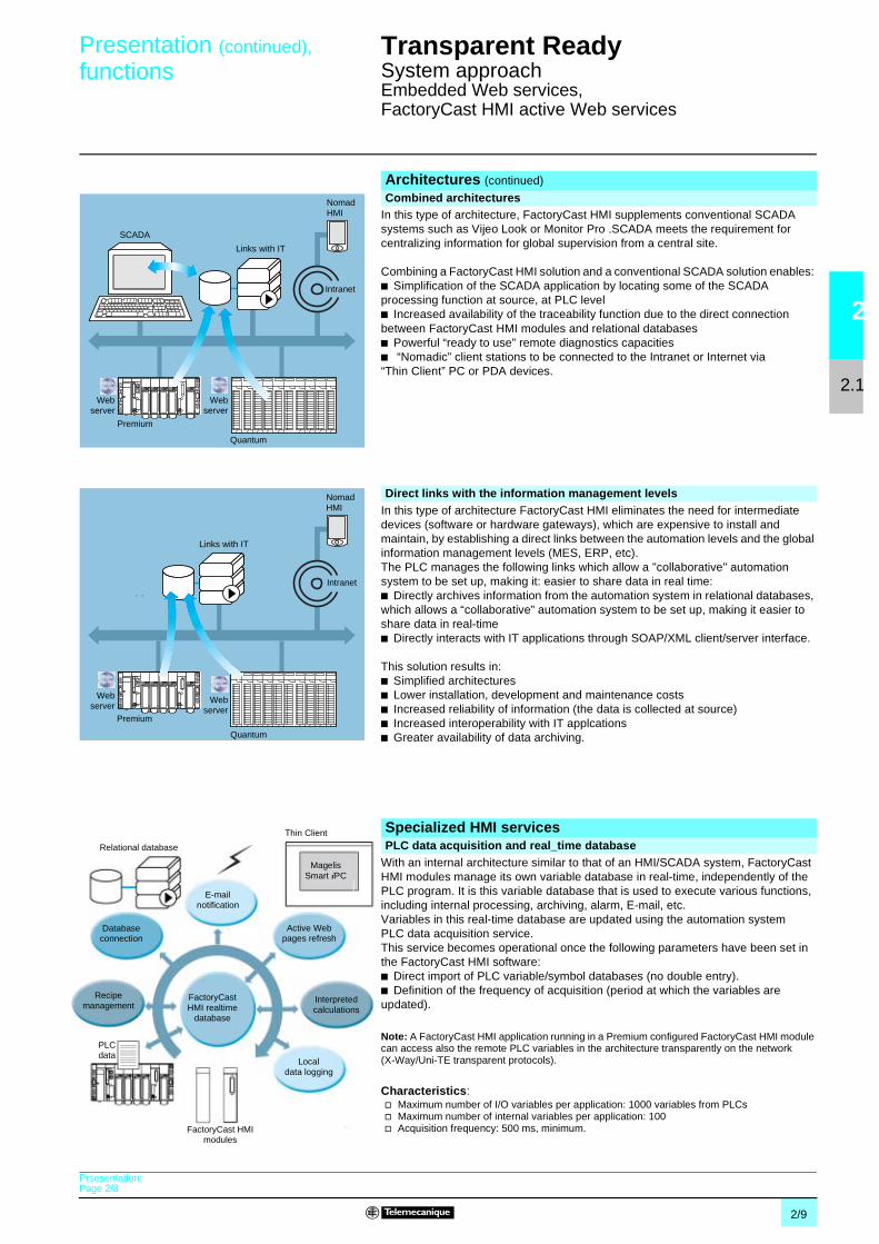
In this type of architecture, FactoryCast HMI supplements conventional SCADAsystems such as Vijeo Look or Monitor Pro .SCADA meets the requirement forcentralizing information for global supervision from a central site.
Combining a FactoryCast HMI solution and a conventional SCADA solution enables:b Simplification of the SCADA application by locating some of the SCADAprocessing function at source, at PLC levelb Increased availability of the traceability function due to the direct connectionbetween FactoryCast HMI modules and relational databasesb Powerful “ready to use” remote diagnostics capacitiesb “Nomadic” client stations to be connected to the Intranet or Internet via“Thin Client” PC or PDA devices.
In this type of architecture FactoryCast HMI eliminates the need for intermediatedevices (software or hardware gateways), which are expensive to install andmaintain, by establishing a direct links between the automation levels and the globalinformation management levels (MES, ERP, etc).The PLC manages the following links which allow a "collaborative" automationsystem to be set up, making it: easier to share data in real time:b Directly archives information from the automation system in relational databases,which allows a “collaborative” automation system to be set up, making it easier toshare data in real-timeb Directly interacts with IT applications through SOAP/XML client/server interface.
This solution results in:b Simplified architecturesb Lower installation, development and maintenance costsb Increased reliability of information (the data is collected at source)b Increased interoperability with IT applcationsb Greater availability of data archiving.
With an internal architecture similar to that of an HMI/SCADA system, FactoryCastHMI modules manage its own variable database in real-time, independently of thePLC program. It is this variable database that is used to execute various functions,including internal processing, archiving, alarm, E-mail, etc.Variables in this real-time database are updated using the automation systemPLC data acquisition service.This service becomes operational once the following parameters have been set inthe FactoryCast HMI software:b Direct import of PLC variable/symbol databases (no double entry).b Definition of the frequency of acquisition (period at which the variables areupdated).
Note: A FactoryCast HMI application running in a Premium configured FactoryCast HMI modulecan access also the remote PLC variables in the architecture transparently on the network(X-Way/Uni-TE transparent protocols).
Characteristics:v Maximum number of I/O variables per application: 1000 variables from PLCsv Maximum number of internal variables per application: 100v Acquisition frequency: 500 ms, minimum.
Architectures (continued)
Combined architectures
SCADA
Links with IT
NomadHMI
Intranet
Quantum
Premium
Webserver
Webserver
Direct links with the information management levels
Quantum
Premium
NomadHMI
Intranet
Links with IT
Webserver
Webserver
Specialized HMI servicesPLC data acquisition and real_time database
PLCdata
FactoryCastHMI realtime
database
FactoryCast HMImodules
Recipemanagement
Thin Client
Relational database
Active Webpages refresh
Databaseconnection
Interpretedcalculations
MagelisSmart iPC
E-mailnotification
Localdata logging
Prsesentation:Page 2/8

2/10
2
2.1
Functions (continued) Transparent Ready 0
System approachEmbedded Web services,FactoryCast HMI active Web services
The FactoryCast HMI server can carry out various arithmetic and logical operationson a combination of variables from the HMI database. These calculations include, forexample, scaling, formatting, logic processing for event triggering, etc.
This calculation function can be used for local data processing independently of thePLC CPU processor and is provided in the form of spreadsheets where the formulaeare defined in cells. The spreadsheets are interpreted and processed by the server.The result of each formula is associated with a new internal variable. The processingof each spreadsheet is initiated by a trigger.
The FactoryCast HMI module can be connected directly and completelyautonomously to the following remote relational databases:b SQL Serverb MySQLb Oracle
This connection enables all internal or process data to be archived directly form theFactoryCast HMI module without any intermediary system (hardware of software).
The data can be archived (written) periodically and/or on a specific event. Thesevariables can either be from PLCs (I/O bits, internal bits, internal words and registers)or local to the module. The FactoryCast HMI "Roll Over" function checks the size oftables by managing the maximum number of records. This circular data archivingfunction automatically deletes the oldest data and can be accessed by simply settingparameters in the FactoryCast HMI software.
Characteristics:v Number of databases that can be connected: 3v Number of tables that can be written per database: 10, maximumv Number of columns per table: 50, maximumv Type of database supported: Oracle, SQL Server and MySQLv Automatic table creation: The FactoryCast HMI server automatically creates a table in the
database if one does not already exist
The FactoryCast HMI module can, on a specific event, send E-mail completelyautonomously to a predefined list of E-mail addresses. This function is executedindependently of the PLC program.
The event that triggers the E-mail may be associated with the following:b A PLC variable (I/O, internal variable)b An alarm, a threshold overshootb A machine or process stateb An operator action, etc.
When an E-mail is sent, it is relayed through an SMTP (Simple Mail Transfer Protocol)server to a destination E-mail address. The E-mail service is compatible with allSMTP servers. A return address can be defined should delivery to the destinationaddress fail.
This E-mail notification is very efficient for advanced remote diagnostic,maintenance, data alarming and reporting. The text of the E-mail can containsinformation such as real-time process values integrated in the message of the mailuseful for reporting additional live information to the end user and also hyperlinks toother Web pages or documents (maintenance guide, schematics, etc) in the moduleor to other Web sites to serve as a guide to the end user.
Characteristics:v Configuration of the SMTP server: Compatible with all SMTP serversv Maximum number of E-mail: 100v Contents of E-mail messages: Free text with embedded dynamic values and hyperlinks
(unlimited).
Specialized HMI services (continued)
Calculation functions
Connection to relational databases
E-mail notification
Prsesentation:Page 2/8

2/11
2
2.1
Functions (continued) Transparent Ready 0
System approachEmbedded Web services,FactoryCast HMI active Web services
FactoryCast HMI modules can process data into a file internally in its flash memory.This file can be either:b exported via FTPb attached to an E-Mail.
This feature is particularly useful for stand alone installations or substations whichare not connected to an intranet or for data storage backup.
For total interoperability purpose, FactoryCast HMI implements SOAP/XML Webservice as a:b Server function so that it can answer to SOAP requests generated by any clientapplication (MES, ERP, SAP, SCADA or third party application running on pNET orJava environment)b Client function so that it can take the initiative to send SOAP requests to a SOAPserver application (another FactoryCast module or an ERP, MES, IT program toexchange data.
See page 2/14 and 2/15.
The recipe function allows FactoryCast HMI application to read “Recipe” filesautomatically on process event or operator command and apply the recipe values bywriting them in a sigle shot to the PLC memory.
This function brings great flexibility in operations providing capability to simplyexecute production changes by modifying manufacturing or process set points andparameters.
Characteristics:v “Recipe” files are described in XML format (SOAP/XML format)v “Recipe” files can be stored locally in the module or on a remote systemv “Recipe” files contain a consistent set of values conforming a recipe template, values which
are written in the PLC memory.
The memory of FactoryCast HMI Web server is open to hosting user defined Webpages in order to provide a graphical HMI interface.Its Active Web server provides a dynamic refresh of the Web pages generated bythe server itself.FactoryCast HMI supports two types of Web pages:b HTML pages animated in real-time with graphical Java objects which are usefulfor creating graphical human machine interface (FactoryCast HMI comes with acomplete graphic objects Java library).b Active Web pages dynamically generated by the server itself with integration ofPLC variables values inside the HTML code (PLC “tags”) which can be used forreporting purpose. These active pages consisting in pure HTML code are fullycompatible either with “thin client” terminal devices such as Pocket PC, PDA, or withany standard PC.
FactoryCast HMI application development software, referencedTLX CD FCHMI V1M, provides multiproject management and complete control ofFactoryCast HMI applications, during both the development and the debuggingphases, thanks to the online mode and simulation mode (operational when thesystem is offline).
This software enables the intuitive and user-friendly setup of HMI functions by simplysetting parameters using a tree structure of the application and can be used forcomplete management of the Web site:b Setting parameters for HMI functions.b Management of the Web site.b Simulation mode.
See page 7/5 for consult product data sheet.
Specialized HMI services (continued)
Local data logging
SOAP/XML client/server interface
Recipe management
Web based HMI interface
FactoryCast HMI application development software
Prsesentation:Page 2/8

2/12
2
2.1
Presentation Transparent Ready 0
System approachEmbedded Web servicesFactoryCast Gateway
FactoryCast Gateway is a new offer of “all in one” intelligent Web gatewaysintegrating, in a stand alone compact unit:b All the TCP/IP network communication and serial link (Modbus or Uni-Telway)interfacesb An RAS (Remote Access server) / IP Router.b A customizable Web server.
TSX ETG 1000/1010 gateways are a low-cost response to the need to integrateserial link installations in an existing Ethernet TCP/IP infrastructure as well asrequirements for remote access services including remote diagnostics, remotemaintenance, remote monitoring and remote control.
Two gateway modules are offered:b TCP/IP – Modbus TSX ETG 1000 gatewayb TCP/IP – Uni-Telway TSX ETG 1010 gateway.
(1) RAS Remote Access Server
Presentation
TSX ETG 1000 TSX ETG 1010
Application examplesIntegration of serial devices (Modbus or Uni-Telway) in an Ethernet TCP/IP network infrastructure
TSX ETG 1000/1010 gateways provide a simple andlow-cost means of integrating any existing Modbus serialRTU or Uni-Telway device, installation or automationisland in an Ethernet TCP/IP network infrastructure.Each gateway is able to make the serial devices (Modbusor Uni-Telway) directly accessible to computermanagement (MES, ERP) or supervision applications inreal-time.
The following serial devices can be used:b On Modbus, with the TSX ETG 1000 gateway: Twidocontrollers, Compact/Momentum/Premium/QuantumPLCs, Altivar drives, Altistart motor starters, Magelisterminals or any other product compatible with the Modbusstandard.b On Uni-Telway, with the TSX ETG 1010 gateway:TSX Micro/Premium/TSX Series 7 PLCs, Altivar drives,Magelis terminals or any other product compatible with theUni-Telway standard.
In addition, its customizable Web server, accessible fromany PC equipped with an Internet browser, offers thefollowing additional services:b Device diagnostics (Modbus or Uni-Telway)b Reading/writing of Modbus registers or Uni-Telwayvariablesb Alarm notification by e-mailb Hosting of user-defined Web pages.
ATV
Uni-Telway
TCP/IP Ethernet
TSX ETG 1000
Modbus
PowerLogicPM500ATVTwido
MagelisSmart iPC
MES/ERPSupervisionWeb client“Thin Client” Web client
Automation island
Intranet
TSX Serie 7XBT
Automation island

2/13
2
2.1
Presentation (continued) Transparent Ready 0
System approachEmbedded Web servicesFactoryCast Gateway
Application examples (continued)Remote diagnostics and remote maintenance Web portal
The addition of the FactoryCast Gateway to anystand-alone machine or automation island creates a trulysophisticated maintenance portal, without any modificationof Modbus or Uni-Telway serial devices..This Web portal offers the following functions:b Configurable Web serverb Alarm notification by e-mailb Remote diagnostics and remote maintenanceb Remote monitoring and control of (Modbus orUni-Telway) variables via predefined Web pages.
Any PC or “Thin Client” terminal (e.g., Magelis Smart iPC)equipped with an Internet browser can be used to accessthese services if it is connected:b Directly to the TCP/IP 1 port on the gatewayb Remotely via the local network, Intranet, Internet, or viaa modem link.
The Web server is fully customizable so that it can beadapted to the user’s requirements. Both the hosting ofWeb pages and any other documents created by the user,and also alarm notification by e-mail mean that the usercan access the essential parameters in a preventivemanner.
From now on, each machine has its own built-inmaintenance.
Remote access to Modbus/Uni-Telway devices via modem
TSX ETG 1000/1010 gateways integrate an RAS (RemoteAccess Server) function, which is compatible with all typesof modem (RTC, GSM, radio modem, etc.), Intranet/VPN(Virtual Private Network) and Internet link.
They support:b PPP (Point to Point Protocol), managing incoming andoutgoing callsb A routing function (IP router) providing transparentaccess to any device present on the Ethernet TCP/IPinfrastructure.b Secure access integrating an embedded filteringfunction for IP client addresses in order to control accesswith password protection (miniature firewall).
This type of connection is suitable for remote maintenanceand remote diagnostics when there are a large number ofsites to be monitored, spread over a wide geographicalarea.
In addition, it can be used to configure and program:b Remote Modbus devices using Telemecanique brandsoftware (Unity Pro, Concept, TwidoSoft, PowerSuite,etc.)b Remote Uni-Telway devices using Telemecaniquebrand software (Unity Pro, PL7 Micro, PL7 Junior/Pro,etc.) and the XIP communication driver.
See page 4/3 for consult TSX ETG 1000/1010 productdata sheet.
(1) XIP communication driver with Uni-Telway TSX ETG 1010gateway
@
TCP/IP Ethernet
TSX ETG 1010
Uni-Telway
TSX ETG 1000
Modbus
MaintenanceDiagnostics Web portal
1
Island/machineIsland/machine
Premium/Quantum
Ethernet TCP/IP
ConceptTwidoSoftPowerSuiteUnity ProPL7, XIP (1)
Maintenance, diagnostics, configuration,programming
Modem
RAS
QuantumAdvantys STB
TSX ETG 10p0
Serial link

2/14
2
2.1
Presentation Transparent Ready 0
System approachSOAP/XML Web services
When the Telemecanique PLC interacts directly with computer managementapplications.
Communication between platforms or applications is now a necessity in a marketwhere e-manufacturing and e-business are an essential fact of life for companies.
Web service technology currently represents the most successful strategy forensuring interoperability of heterogeneous software applications via an Intranet orthe Internet, independently of any platform, operating system and programminglanguage.
The standardisation of Web services has come about as a result of joint developmentbetween Microsoft and IBM, amongst others, validated at the W3C (World WideWeb Consortium) as an open “standard”.It now provides all the tools, specifications and environments needed for eachplatform.
Web services are based on standards such as:b XML (eXtensible Markup Language): the universal standard for data exchangeb SOAP (Single Object Access Protocol) protocol carried via the HTTP (Hyper TextTransfer Protocol) channel.b WSDL (Web Services Description Language) the Web Services descriptionlanguage, in XML format.
SOAP is currently considered to be the reference protocol, including in industry. Ithas since been adopted by the main players such as Microsoft (pNET, SQL Server,Office, etc), IBM (Java, Web Sphere), Lotus, ORACLE, Sub, SAP, ...
It becomes now also available in control system equipment within the FactoryCastWeb server offer embedded in the Telemecanique PLCs.
The Telemecanique PLC integrates the Web services standard.
This new Transparent Ready service offers the previously unused (or uncommon)possibility of making an IT/e-business application interact directly with the controlsystem levels using the same standards.With the implementation of ModbusXMLDa (Modbus XML Data access) Webservices in FactoryCast Web servers, the IT engineer can easily create his ownapplication which will access the desired information directly in the PLC and in realtime.Data exchanges are made in XML standard format in response to a request usingSOAP protocol.
The implementation of Web services in control system equipment makes it easy toachieve vertical integration of the control level and the creation of even morecollaborative architectures which can be used to link production systems to thecorporate management systems. It brings simplified access to information, areduction in the costs of training, development and deployments costs, plus anincrease in productivity.
PresentationSOAP/XML Web Services embedded in the PLC
Embedded SOAP/XML Web Services: ModbusXMLDa Web services

2/15
2
2.1
Presentation (continued) Transparent Ready 0
System approachSOAP/XML Web services
This implementation enables a SOAP client application (management levelcomputer application, MES, ERP, etc) to communicate directly with a FactoryCastWeb server module embedded in the PLC.Exchanges are initiated by the SOAP client application (the server responds to theserequests).
b Step 1: Creation of the client application with learning of the Web services.The development environment (for example, Visual Studio pNET) looks in theFactoryCast server for the list of available services and their WSDL standardinterfaces provided by the module.b Step 2: Development of the client application. The developer integrates theWeb service functions using the code retrieved at the learning stage.b Step 3: Execution of the client application. The client application communicatesin real time with the FactoryCast Web server module using the SOAP protocol.
This implementation allows a FactoryCast HMI module to execute a SOAP clientapplication in order to communicate with a remote SOAP server application (forexample another FactoryCast Web server module or a computer managementapplication, MES, ERP, etc).
Exchanges are initiated by the FactoryCast HMI client module (the remoteapplication server responds to SOAP requests sent by the FactoryCast HMI module).
b Step 1: Configuration of ModbusXMLDa client service. The user declares thePLC variables that are to be exchanged (in read or write mode), using theFactoryCast HMI configuration software.b Step 2: Use of the application. ModbusXMLDa client service executed in theFactoryCast HMI module communicates directly with the remote server applicationusing SOAP requests in XML format.
The ModbusXMLDa functions are implemented in the following FactoryCast PLCmodules.
Requests implemented in the FactoryCast modules listed provide either physical orsymbolic variables data access. They are defined in the table below.
Implementation of the ModbusXMLDa Web services inFactoryCast modulesModbusXMLDa server interface
1, 2
3
SOAPrequest
WSDL
Visual Studio pNET
pNET Java
RunTime client
FactoryCastmodule
SOAPserver
Development tool
ModbusXMLDa client interface
1
2
SOAPrequest
Configuration
FactoryCast orFactoryCastHMImodule
SOAPserver
FactoryCast HMImodule
FactoryCast HMI software
SOAPclient
Selection guide and list of implemented SOAP requests
ModbusXMLDa interface FactoryCast modules FactoryCast HMI modulesServer TSX ETZ 510 TSX Micro module
TSX ETY 5103 Premium module140 NOE 771 11 Quantum module
TSX WMY 100 Premium module140 NWM 100 00 Quantum module
Client – TSX WMY 100 Premium module140 NWM 100 00 Quantum module
Access to data via ModbusXMLDa functions implemented in FactoryCastmodules
Physical address ReadDeviceIdentification
ReadMultipleRegistersWriteMultipleRegistersReadCoils
WriteMultipleCoilsReadDiscreteInputs
Symbol Read, operation to read item list valueWrite, operation to write item list value
Browse, operation to browse item list

2/16
2
2.2
Presentation Transparent Ready 0
System approachEthernet TCP/IP communication service
Transparent Ready products allow transparent communication on a single EthernetTCP/IP network.
In addition to universal Ethernet services (HTTP, BOOTP/DHCP, FTP, etc), theTransparent Ready device communication services designed for use in automationapplications include:b Modbus TCP/IP messaging for class 10, 20 or 30 devices.b I/O Scanning service for class 30 devices.b FDR (Faulty Device Replacement) for class 10, 20 or 30 devices.b SNMP (Simple Network Management Protocol) network administration for class20 or 30 devices.b Global Data, for class 30 devices.b Module Bandwidth Monitoring for class 30 devices (see performance levels onpages 2/28 to 2/31).b NTP (Network Time Protocol) time synchronization for class 30 devices.b E-mail notification of application events via SMTP for class 30 devices.b TCP Open, optional, for class 30 devices.
The following pages present the various options available through all of theseservices in order to facilitate the optimum choice of solutions when defining a systemintegrating Transparent Ready devices.
Presentation
Services
Applica-tions
Transport
Link
Physical
Networkmanage-ment
GlobalData
FDR Faulty Device Replacement Webserver
Messagehandling
ModbusI/OScanning
SNMP RTPS DHCP TFTP FTP HTTP Modbus
UDP TCP
IP
Ethernet 802.3 and Ethernet II
MIB
Tra
nsp
aren
tR
ead
y
TCP OpenE-mail
SMTP
Timesynchroni-zation
NTP

2/17
2
2.2
Functions Transparent Ready 0
System approachEthernet TCP/IP communication service
The HTTP protocol “Hypertext Transfer Protocol” is used for transmitting Web pagesbetween a server and a browser. HTTP has been used on the Web since 1990.
Web servers embedded into Transparent Ready devices are used to provide easyaccess to devices anywhere in the world from a standard browser such as InternetExplorer or Netscape Navigator.
BOOTP/DHCP is used to automatically provide the devices with the IP parameters.This avoids having to manage the addresses of each device individually.Management is instead performed in a dedicated IP address server.DHCP protocol (Dynamic Host Configuration Protocol) is used to automaticallyassign the devices their configuration parameters. DHCP is an extension of BOOTP.DHCP protocol is made up of 2 components:b One for providing the IP network address,b One for providing the IP parameters specific to the device from a DHCP server.
Telemecanique devices can be:v BOOTP clients allowing automatic recovery of an IP address from a server,v BOOTP servers enabling a device to distribute IP addresses to the networkstations.Telemecanique uses standard BOOTP/DHCP protocols for its Faulty DeviceReplacement service (FDR).
File Transfer Protocol (FTP) provides basic file sharing elements. Many systems useFTP protocol to exchange files between devices.
Trivial File Transfer Protocol (TFTP) is A network transfer protocol that allows toconnect to a device and download code onto it. For example, it can be used to shoveboot code onto a diskless workstation, or connect and download firmware updates tonetworking devices
Note: Transparent Ready devices implement FTP and TFTP for transferring certain data to orfrom devices, in particular when downloading firmware or user Web pages.
FunctionsStandard Ethernet servicesHTTP “Hypertext Transfer Protocol” (RFC1945)
BOOTP/DHCP (RFC1531)
FTP “File Transfer Protocol” (RFCs 959, 2228, et 2640)
TFTP "Trivial File Transfer Protocol" (firmware updates of networking devices)
2/18
2
2.2
Functions (continued) Transparent Ready 0
System approachEthernet TCP/IP communication service
NTP (Network Time Protocol) is used to synchronize the time of a client or serverdevice from a time server. Depending on the network used, it provides the followingtime precisions based on the UTC:b Several milliseconds on a local area network (LAN).b Several tens of milliseconds on a wide area network (WAN).
SMTP (Simple Mail Transfer Protocol) is an E-mail transmission service. It is used tosend E-mail between a sender and a recipient via an SMTP E-mail server.
The Internet community developed standard SNMP for managing the differentcomponents of a network through a single system. The network management systemcan exchange data with SNMP agent devices. This function enables the manager toview the status of the network and devices, modify their configuration and feed backalarms in the event of failure.
Note: Transparent Ready devices are SNMP-compatible and can be integrated naturally in anetwork managed via SNMP.
COM/DCOM (Distributed Component Object Model) or OLE (Object Linking andEmbedding) is the name of the technology used in Windows components. Thisenables Windows applications to communicate transparently.
Note: These technologies are used in the OFS Data server software.
Functions (continued)
Standard Ethernet services (continued)NTP “Network Time Protocol” (RFC 1305)
SMTP “Simple Mail Transfer Protocol” (RFC 0821)
SNMP “Simple Network Management Protocol” (RFCs 1155, 1156 et 1157)
COM/DCOM “Distributed Component Object Model”
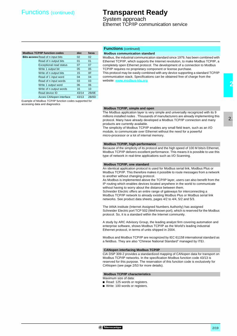
2/19
2
2.2
Functions (continued) Transparent Ready 0
System approachEthernet TCP/IP communication service
Modbus, the industrial communication standard since 1979, has been combined withEthernet TCP/IP, which supports the Internet revolution, to make Modbus TCP/IP, acompletely open Ethernet protocol. The development of a connection to ModbusTCP/IP requires no proprietary component or license purchase.This protocol may be easily combined with any device supporting a standard TCP/IPcommunication stack. Specifications can be obtained free of charge from thewebsite: www.modbus-ida.org
The Modbus application layer is very simple and universally recognized with its 9millions installed nodes . Thousands of manufacturers are already implementing thisprotocol. Many have already developed a Modbus TCP/IP connection and manyproducts are currently available.The simplicity of Modbus TCP/IP enables any small field team, such as an I/Omodule, to communicate over Ethernet without the need for a powerfulmicro-processor or a lot of internal memory.
Because of the simplicity of its protocol and the high speed of 100 M bits/s Ethernet,Modbus TCP/IP delivers excellent performance. This means it is possible to use thistype of network in real-time applications such as I/O Scanning.
An identical application protocol is used for Modbus serial link, Modbus Plus orModbus TCP/IP. This therefore makes it possible to route messages from a networkto another without changing protocol.As Modbus is implemented above the TCP/IP layer, users can also benefit from theIP routing which enables devices located anywhere in the world to communicatewithout having to worry about the distance between them.Schneider Electric offers an entire range of gateways for interconnecting aModbus TCP/IP network to already existing Modbus Plus or Modbus serial linknetworks. See product data sheets, pages 4/2 to 4/4, 5/2 and 5/3.
The IANA institute (Internet Assigned Numbers Authority) has assignedSchneider Electric port TCP 502 (Well known port), which is reserved for the Modbusprotocol. So, it is a standard within the Internet community.
A study by ARC Advisory Group, the leading analyst firm covering automation andenterprise software, shows Modbus TCP/IP as the World’s leading industrialEthernet protocol, in terms of units shipped in 2004.
Modbus and Modbus TCP/IP are recognized by IEC 61158 international standard asa fieldbus. They are also “Chinese National Standard” managed by ITEI.
CiA DSP 309-2 provides a standardized mapping of CANopen data for transport onModbus TCP/IP networks. In the specification Modbus function code 43/13 isreserved for this purpose. The reservation of this function code is exclusively forCANopen (see page 2/53 for more details).
Maximum size of data:b Read: 125 words or registers.b Write: 100 words or registers.
Functions (continued)
Modbus communication standardModbus TCP/IP function codes dec hexaBits access Read of n input bits 02 02
Read of n output bits 01 01Exceptional read status 07 07Write 1 output bit 05 05
Write of n output bits 15 0FRead of 1 input word 04 04Read of n input words 03 03
Write 1 output word 06 06Write of n output words 16 10Read device ID 43/14 2B/0E
Acces CANopen interface 43/13 2B/0DExample of Modbus TCP/IP function codes supported foraccessing data and diagnostics
Modbus TCP/IP, simple and open
Modbus TCP/IP, high-performance
Modbus TCP/IP, one standard
CANopen interfacing Modbus TCP/IP
Modbus TCP/IP characteristics

2/20
2
2.2
Functions (continued) Transparent Ready 0
System approachEthernet TCP/IP communication service
The I/O Scanning service can be used to manage the exchange of distributed I/Oson the Ethernet network after a simple configuration operation, with no need forspecial programming.The I/Os are scanned transparently by means of read/write requests according to theModbus Master/Slave protocol on the TCP/IP profile. This principle of scanning viaa standard protocol enables communication with any device which supports aModbus server on TCP/IP.This service can be used to define:b An %MW word zone reserved for reading inputsb An %MW word zone reserved for writing outputsb Refresh periods independent of the PLC scan.During operation, the module:b Manages the TCP/IP connections with each of the distributed device.b Scans the devices and copies the I/Os into the configured %MW word zoneb Feedback status words so that correct operation of the service can be monitoredfrom the PLC applicationb Applies the preconfigured fallback values in the event of a communicationproblem.
An offer of hardware and software products which enable the I/O Scanning protocolto be implemented on any type of product which can be connected to the Ethernetnetwork (please consult: www.modbus-ida.org).
b Each station can exchange, with Unity software a maximum of:v 100 words for writingv 125 words for reading.b Maximum size in the PLC managing the service:v 2 K words %MW (1) in inputs and 2 K words %MW (1) in outputs with manager PLC
(64 stations max.)v 4 K words %MW (1) in inputs and 4 K words %MW (1) in outputs with manager PLC
(128 stations max.).
I/O Scanning service diagnostics can be performed in 3 ways:b By the application program from a data field specific to the PLCb From the debugging screen in the programmingssoftwareb From the PLC system diagnostics function viewed with the Internet browser on aPC station.
(1) or 4x registers with Concept or ProWORX.
Functions (continued)
I/O Scanning service
INPUT
OUTPUT+–
INPUT
OUTPUT+–
A
B
A
B
Word table
Read Write
Ethernet TCP/IP
Input wordsOutput words ofdevices
Characteristics
I/O Scanning service diagnostics

2/21
2
2.2
Functions (continued) Transparent Ready 0
System approachEthernet TCP/IP communication service
The Faulty Device Replacement service uses the standard BOOTP/DHCP, filemanagement and TFTP (Trivial File Transfer Protocol) technologies with theobjective of simplifying Ethernet device maintenance.
It enables a faulty device to be replaced by a new product while guaranteeing itsdetection, reconfiguration, and automatic restart by the system, without difficultmanual intervention.
The principal steps are:1 A device using the FDR service is faulty.2 Another similar device is taken from the maintenance pool, preconfigured with the
“Device_name” (or identifier) of the device that is out of service, then reinstalled on thenetwork. The identifier is set by the position of the rotary switches, as for Advantys STB, a orAdvantys OTB distributed I/O. The “Device_name“ should be given with a keypad, for Altivarvariable speed drives.
3 The FDR server detects the new addition, configures that device’s IP address and transfersthe configuration paramaters to it:
4 The substituted device verifies if all the parameters are indeed compatible with its owncharacteristics, then switches to operating mode.
The FDR server can be:v Premium processor with embedded Ethernet TSX P57 ppppM,v Quantum processor with embedded Ethernet 140 CPU 651 50/60,v Premium Ethernet module: TSX ETY 4103/5103,v Quantum Ethernet module: 140 NOE 771 01/11.See pages 6/6 to 6/10.
Functions (continued)
FDR (Faulty Device Replacement), replacement service for faulty devices
a

2/22
2
2.2
Functions (continued) Transparent Ready 0
System approachEthernet TCP/IP communication service
The Global Data service ensures data exchanges in real-time between stationsbelonging to the same distribution group. It is used to synchronize remoteapplications, or share a common database among several distributed applications.The exchanges are based on a standard producer/consumer protocol, guaranteeingoptimal performance while maintaining a minimum network load. This RTPS(Real-Time Publisher Subscriber) protocol is promoted by the Modbus-IDAorganization (see page 2/2), and has already been adopted as a standard by severalmanufacturers.
A maximum of 64 stations can participate in Global Data within the same distribution group.Each station can:b Publish one 1024-byte variable. The publication period can be configured from 1 to n periods
of the Mast task of the processor.b Subscribe to between 1 and 64 variables. Validity for each variable is controlled by Health
Status Bits, linked to a refresh timeout configurable between 50 ms and 1 s. Access to avariable element is not possible. The total size of the subscribed variables reaches 4 Kcontiguous bytes.
In order to optimize Ethernet network performance further still, Global Data can beconfigured with the "multicast filtering" option, which together with switches in theConneXium range (see pages 8/4 to 8/6) , perform data broadcasting only onEthernet ports, where there is a Global Data service subscriber station. If theseswitches are not used, Global Data is transmitted in "multicast" on all switch ports.
The diagnostics screensuse a color code to showGlobal Data status:bConfigured/notconfigured/faulty.bPublished/subscribed.
Functions (continued)
Global Data service
Distribution group 1Data exchange of 4 Ko max.
Distribution group 2
IP multicast 239.255.255.251
IP multicast 239.255.255.250
Ethernet TCP/IP
Data exchange of 4 Ko max.
Characteristics
Global Data service diagnostics

2/23
2
2.2
Functions (continued) Transparent Ready 0
System approachEthernet TCP/IP communication service
The time synchronization service is based on the NTP (Network Time Protocol)which is used to synchronize the time of a client or a server on Ethernet TCP/IP froma server or another reference time source (radio, satellite, etc).
Some Ethernet communication modules (140 NOE 771 11 with the ModiconQuantum Unity V2.0 (or more) and TSX ETY 5103 with Premium Unity V2 (or more)automation platforms) have an NTP client component. These modules can connectto an NTP server using a client request (unicast), in order to update their local time.The module clock is updated periodically (1 to 120 seconds) with an error of less than10 ms for standard processors and less than 5 ms for high performance processors.If the NTP server cannot be reached, the Ethernet TCP/IP module switches to astandby NTP server.
(1) Time difference between field input and central NTP server.(2) Assuming input connected to the interrupt module.
The PLC processor clock is therefore itself updated with a precision of 5 ms forstandard processors and 1 ms for high performance processors. A function block isavailable for reading this clock. In each PLC application, events or variables can betime-stamped.
The Ethernet module is configured via a Web page. The time zone can beconfigured. A time synchronization service (NTP) diagnostic Web page is alsoavailable.
Information on the time synchronization service (NTP) is also available in theTransparent Ready private MIB, which can be accessed via the SNMP networkmanagement service (see above).
Functions (continued)
NTP time synchronization servicePresentation
Powersupply
Processor Ethernetmodule
Internalclock
Ethernet network
NTPserver
Premium/QuantumNTP response
NTP request
(S)NTPclient
Operation
Ethernet module associated with its Unity processor Predicted typical time service precisionEthernet modules Unity processors Clock synchronisation (1) Event synchronisation Time stamping (2)TSX ETY 5103 TSX P57 0244M
TSX P57 1p4MTSX P57 2p4MTSX P57 3p4M
± 1 ms typical± 10 ms max.
=Clock
synchronisationprecision
+
Fast task time
+
I/O time
=Clock
synchronisationprecision
+
I/O time
TSX P57 4p4MTSX P57 5p4M
± 1 ms typical± 5 ms max.
140 NOE 771 11 140 CPU 311 10140 CPU 434 12U140 CPU 534 14U
± 1 ms typical± 10 ms max.
140 CPU 651 50140 CPU 651 60140 CPU 671 60
± 1 ms typical± 5 ms max.

2/24
2
2.2
Functions (continued) Transparent Ready 0
System approachEthernet TCP/IP communication service
This simple mail notification service is a programmed service that allows PLCapplications to report by exception conditions monitored by the PLC. The automationcontroller can automatically and dynamically create electronic mail to alert specifiedusers with data, alarms and events - whether the recipients are local or remote.
Note: This service is available on the latest Premium and Quantum Ethernet modules& CPUs, when operating with Unity Pro software. A more comprehensive mailservice, independent of the PLC application, is available on the FactoryCast HMIactive web server modules (see page 2/11)
A simple yet powerful mechanism is used. Predefined email headers are linkedtogether with the body of the mail which is created dynamically from the latestinformation in the automation application.
The user logic program can trigger the message based on a predefined event orcondition. Using a function block, one of 3 predefined headers is selected and anemail message with variable information and text (up to a maximum of 240 bytes) iscreated and sent directly from the PLC.
Each of the three mail headers contains these common predefined items –emailrecipient list, sender name and subject. This information can be defined and updatedby an authorized administrator using the configuration web pages.
The PLC application selects the appropriate header. The system architect maydefine the mail headers to indicate differing importance levels. For example :b Header 1 could be “URGENT problem reported by PLC 10”,b Header 2 might be “WARNING at substation 10”,b Header 3 could be “INFO message from water system”.
Differing lists of recipients between the three headers help to ensure that the rightinformation quickly flows to the right recipients. The application can then addpertinent information to the body of the mail message such as the specific device,process or location.
Completed mail is then sent to an electronic mail server for expeditious distributionto the interested parties. These recipients could be engineers, managers, processowners etc.
Each mail message can be protected by an optional login and password that isauthenticated by the SMTP mail server. If, for additional security, the site’s mailinstallation has changed the TCP port number from the default of 25, the port numbercan be changed in the PLC email configuration (via secured web page access).
An authorized administrator can use a web page to easily configure the mail service.For each of the three mail headers, the sender; recipient list and subject messagecan be defined. The electronic mail server connection information such as IP addressand security information can also be set from the web page.
As all other Ethernet services in Premium and Quantum systems, the Mail Servicehas a Diagnostic Web page showing the complete, up to the second, status.
These products provide diagnostic information for remote management applicationsfollowing the SNMP network management standard. Information for the mail serviceis included in the Schneider Electric private MIB which is publicly available.
Functions (continued)
SMTP electronic mail notification serviceIntroduction
Usage
Message creation and delivery
Security
Configuration
Diagnostics
Remote Monitoring

2/25
2
2.2
Functions (continued) Transparent Ready 0
System approachEthernet TCP/IP communication service
The SNMP (Simple Network Management Protocol) protocol is used, from a networkmanagement station, to monitor and control all Ethernet architecture componentsand thus ensure rapid diagnostics if a problem occurs.It is used to:b Query devices such as computer stations, routers, switches, bridges or terminaldevices (DTE) in order to view their statusb Obtain statistics for the network on which the devices are connected.
This management software respects the traditional Client/Server model. However, inorder to avoid confusion with other communication protocols using this terminology,we prefer to use these definitions:b IntraVUE from Network vision (see partner sheet page 9/17)b Network manager for the Client application running on the computer stationb SNMP agent for the server application that runs on the device.Transparent Ready can be managed by any SNMP network manager, includingHP Openview or IBM Netview.
Standard SNMP (Simple Network Management Protocol) is used to accessconfiguration and management objects included in the MIB (ManagementInformation Base) for the devices. These MIBs must comply with certain standardsin order to be accessed by all managers on the market. However, depending on thedevice complexity, manufacturers can add certain objects to the private databases.
The Transparent Ready private MIB includes management objects specific to theTelemecanique offer. These objects simplify installation, implementation, andmaintenance for Transparent Ready products in an open environment usingstandard network management tools.
The Transparent Ready products support 2 SNMP network management levels:b Standard MIB II, a first level of network management, can be accessed via thisinterface. It lets the manager identify the devices forming the architecture andretrieve general information on the configuration and operation of the EthernetTCP/IP interfaceb MIB Transparent Ready interface; management of the Transparent Ready devicesis improved via this interface. This MIB includes a set of data that enables thenetwork management system to supervise all the Transparent Ready services.The Transparent Ready private MIB can be downloaded from the Web server fromany Ethernet Transparent Ready module in a PLC.
Functions (continued)
SNMP service protocol

2/26
2
2.2
Functions (continued) Transparent Ready 0
System approachEthernet TCP/IP communication service
TSX ETY 110 WS/5103 Premium platform Ethernet modules support a number ofcommunication protocols based on the TCP/IP standard.Among these, the Modbus protocol has public specifications and its simplicityrecommends it for the needs of communication with third-party devices.
However, for certain applications, it may prove necessary to use other protocols.This is the case when, for example, users wish to integrate Modicon Premiumplatforms into existing architectures which use a particular communication protocol,possibly a proprietary one.To meet these needs for open access, 2 interface levels are included in theTelemecanique offer:b A library of basic functions, which can be used in C language, enables directaccess to the socket interface on TCP. The user can thus create his owncommunication functions using SDKC development software and take advantage ofthe ease of use which this program offers in terms of development and debugging.Once generated, these function blocks are used in the application like any standardPL7 or Unity Pro programming software function block.b A library of basic function blocks known as EFs, which can be used directly in theapplication programs with PL7 Unity Pro language. These are the same as functionsdeveloped in C language seen earlier, but are designed for use by non-computerspecialists. These EF function blocks are not modifiable.
Operating in TCP connection client/server mode, the basic functions on the Berkeleysocket interface enable:
b Management of 16 connections on the Open profile out of a maximum of 32b Creation of sockets and their attachment to any TCP portb Switching of these sockets to "listen for a connection request from a remote client"modeb Opening of a connectionb Transmission and reception of data on these connections (8 bytes max.)b Closing this connection.
TCP Open optional servicePresentation
Ethernet TCP/IP profile
Modbus protocol
DirectSocket access
(TCP Open)
TCP
IP
ISO 802.2-ISO 802.3
ISO 802.3 Ethernet10/100 Mbit/s
Modbus
Functions

2/27
2
2.2
Functions (continued) Transparent Ready 0
System approachEthernet TCP/IP communication service
The TCP Open offer consists of a CD-ROM containing the TCP/IP function libraries.Open access on TCP is only possible via TSX ETY 110WS (1) and TSX ETY 5103Ethernet modules. With open access on TCP, all the basic functions of thesemodules can be used.
The TCP/IP TLX CD TCP 50M function library comprises:b The SDKC program enhancement library that provides access to the moduleTCP/IP socket functionsb The user's manual in English (no printed version)b EF elementary communication function blocks (Socket/Bind/Listen/Accept/Shutdown/Close/Send/Receive/Select/Set_Socket Option/Connect) for installationusing PL7 software (version u V3.3)b Higher level EF function blocks, provided by way of example, which can performmore advanced functions such as the complete sequence for establishing or closinga connection, or sending or receiving data. The source files for all these EF blocksare also suppliedb An example of a PL7 application communicating with a TELNET application ona PC.
If customised function blocks are needed both:b the SDKC program for C language:v UNY SPU ZU CD 20E (with Unity Pro software)v or TLX L SDKC PL741M (with PL7 software)b and the library of function blocks TCP Open TLX CD TCPA50Mshould be installed on the development station (see references page 6/7).
The development of C language functions requires compliance with certain setupprecautions:b To set up these services, the user should be familiar with the TCP/IP profileb In addition, since the SDKC program enables access to all the PLC internalresources, all the necessary precautions should be taken when developing EFcommunication blocks to avoid endangering the PL7 application, especially on thecommonly fragile operating modes such as cold/warm restarts, response to a fault, etcb The user should also take care to maintain the requests from the differentcommunication profiles at a level compatible with the performance required by theapplicationb Finally, it is the responsibility of the client application software (PL7, Unity Pro orC program) to manage the operating modes for communication which may bespecific to the application, for example the behavior if a remote device fails torespond or in the event of a break in connection.
For these different reasons, we recommend that you consult your Regional SalesOffice to ensure that your TCP protocol open access project is feasible.
(1) Open access on TCP requires TSX ETY 110 WS modules, version u PV 03 and SV 2.9. Inaddition, it should be integrated on a configuration with a TSX P57 pp3 processor(or TSX P57 pp2 version > V3.3).
TCP Open optional service (continued)
Description
Setup precautions

2/28
2
2.3
Performances Transparent Ready 0
System approachPerformance of Ethernet TCP/IP network
When selecting an architecture, it is advisable to take performance into account atthe earliest possible stage.
When selecting an architecture, the designer must:1 Have a clear idea of his needs as regards:v quantity and type of devices to be interconnectedv volume and type of exchangesv expected response timesv environment.2 Compare his needs with the characteristics of the offers available and be aware
that the precise performance level between any 2 points on an architecture isdependent on the weakest link in the chain, which can be:
v a function of the hardwarev but also a function of the applications (size, architecture, OS, machine power, etc.)which are often poorly defined at this stage of project.3 Select the most suitable architecture.
The objective of the following pages is to provide main information and guidelines tohelp answering the second point. As performance of an Ethernet architecture islinked to numerous parameters, those pages are not delivering all informationneeded for a complete calculation of the network performance. They intend toconcentrate on the following key aspects:b Guidelines to evaluate the network load to design an Ethernet networkanswering the application requirement. As network load calculations requirenumerous parameters we will not intend to describe the whole calculationmethodology, but to deliver main guidelines, see pages 2/28 to 2/31b Application response time that should be reached depending of theconfiguration used, see page 2/33b Processing capabilities of Modicon Premium and Modicon Quantum PLCsto determine the CPU and the number of Ethernet connection required on PLC,depending of the application, see pages 2/34 and 2/35.
To evaluate the network load of an Ethernet network, calculations of all thecommunication services of all devices connected to the network are required. Due toEthernet high performances, in most cases the load will be easily below the Ethernetnetwork limits and will not have a significant effect on the total application responsetime. It’s due to the high speed of Ethernet: the network transaction time is less than10% of the total application response time. To ensure a low network load andavoiding huge theoretical calculation, it is strongly recommend to separate thecollision domain to limit the network load, using only switched network (tree, star ordaisy chain topology), see pages 2/37 and 2/38.
The following are guidelines to evaluate the network load. Only switched or daisychain networks should be used avoiding the system evaluation inside the collisiondomains.
Guidelines are only for the following Ethernet communication services:b TCP/IP Modbus messagingb I/O Scanningb Global Data.
Other services (as Faulty Device Replacement, Network management SNMP,Web…) and transactions management (account retries and collisions,bandwidth used for establishment and management of the services…) are nottaken into consideration in the evaluation guidelines.
Selecting the communication architecture
Guidelines to evaluate the network loadIntroduction

2/29
2
2.3
Performances (continued) Transparent Ready 0
System approachPerformance of Ethernet TCP/IP network
For the evaluation of the bandwidth used by I/O Scanner it’s necessary to have thefollowing characteristic parameters of each scanned station:
Nota : The scanning period is limited by scanned device response time.
The evaluation of the network load of the I/O Scanner service in bit/s is made withthe following formula:(103 + 2 x size of the read variables + 95 + 2 x size of the write variables)x8000 / period of scanningThe calculation must been made for each scanned device of each scanning station.
Guidelines to evaluate the network load (continued)
Evaluation of TCP/IP Modbus messagingEvaluation of bandwidth used by TCP/IP Modbusmessaging is particularly complex because a lot ofparameters are changing for each requestedtransaction of the application program.
Transaction periodicityPeriodicity of transaction is not so simple to determine.The request could be sent at the task period of theinitiator, but the response is depending on the taskperiod of the destination station. If there is a lot of trafficon the network, the response may take several periods.All these parameters have to be evaluated beforeentering the period of the transactions.
Length of messagesb One part of the message has always the samelength, due to successive encapsulations:Ethernet (26), IP (24), TCP (24), andModbus-MBAP (7), giving a total of 81 bytes, to this12 bytes is added wihich corresponds to theInter Packet Gapb Second part of the frame has a length, whichdepends of the length of Modbus PDUrequest/response and its parameters. The differentcases are listed in the attached table (value in bytes).
Nota :(1) N = Number of coils / 8 or
N = Number of coils / 8 + 1 (remainder ≠ 0)(2) N = Number of inputs / 8 or
N = Number of inputs / 8 + 1 (remainder ≠ 0)(3) N = Number of registers x 2(4) Ki = Length of object i; with i = 1 to n,
where n = number of objects.
For the evaluation of the bandwidth used byModbus TCP/IP messaging it’s necessary to have thefollowing characteristic parameters for eachtransaction:1 Period of sending message2 Size of the Modbus PDU of the request3 Size of the Modbus PDU of the response
in msin bytesin bytes
The evaluation of the network load of the Modbus TCPmessaging service in bite/s is made with the followingformula:(186 + size of the Modbus PDU of the request +size of the Modbus PDU of the response)x8000 / period of sending messageThe calculation must been made for each scanneddevice of each transaction.
Evaluation of I/O Scanner
1 Period of scanning2 Size of the read variable3 Size of the write variable
in msin wordsin words
Modbus request/response Total PDU Functioncode
Param. Datas
length length length lengthRead coils (01)
Request 5 1 4 0Response 2 + N 1 1 N
Read discrete inputs (02)Request 5 1 4 0Response 2 + N 1 1 N
Read holding register (03)Request 5 1 4 0Response 2 + N 1 1 N
Read input register (04)Request 5 1 4 0Response 2 + N 1 1 N
Write single coil (05)Request 5 1 4 0Response 5 1 4 0
Write single register (06)Request 5 1 4 0Response 5 1 4 0
Write multiple coils (15)Request 6 + N 1 5 NResponse 5 1 4 0
Write multiple registers (16)Request 6 + N 1 5 NResponse 5 1 4 0
Read file record (20)Request 9 1 8 0Response 4 + N 1 3 N
Write file record (21)Request 9 + N 1 8 NResponse 9 + N 1 3 N
Mask Write registers (22)Request 7 1 6 0Response 7 1 6 0
Read/write multiple registers (23)Request 10 + M 1 9 MResponse 2 + N 1 1 N
Read device identification (43)Request 4 1 3 0Response 7 + Σ(2 + Ki) 1 6 Σ(2 + Ki)

2/30
2
2.3
Performances (continued) Transparent Ready 0
System approachPerformance of Ethernet TCP/IP network
For the evaluation of the bandwidth used by the Global Data service, it’s necessaryto have the list of all the variables belonging to the same Multicast group, with theircharacteristic parameters:
These parameters must be collected in each station publishing at least one variablein the Multicast group.
The evaluation of the network load of the global data service in bite/s is made withthe following formula:(Size of variable x 2 + 90) x (1000 / (Period of Mast Task x distribution period)This calculation must been made for all variables of all Multicast groups.
Previous evaluations give indication of traffic when consideringb One station when sending Messages or I/O Scanner requestsb A group of stations belonging to the same Global Data group.
The final objective is to have an evaluation of traffic when connecting severalstations.
Following information are required for each station:b Level of traffic the station has to manage (sum of I/O Scanning, messaging andGlobal Data) calculated previouslyb Collision domain to which the station belongs.
Additional information are required for Global Data traffic:b Level of traffic in each Global Data group, calculated previouslyb List of stations belonging of Global Data groups.
First step of system evaluation, is traffic calculation inside each collision domain. Acollision domain, is a domain where hub as used. A switch separates two domains.If only a switched or daisy chain network infrastructure is used (it is stronglyrecommended to have the lowest possible network load) go directly to the next step.If you use hubs add all traffic of all stations connected to the same collision domain.The table below facilitate the calculation:
Second step is traffic evaluation between collision domains. If only switches anddaisy chain are used (avoiding using 2 hubs is recommended) it’s only necessary toadd the messages transmitted on each link. If hubs are used somewhere in theapplication, in this step add only the traffic from one hub domain to the other (e.g.going through one switch).
Guidelines to evaluate the network load (continued)
Evaluation of Global Data
1 Distribution period2 Period of Mast Task3 Size of variable
in number of scanin msin number of words
System evaluation
Messages transmitted per bit/s from Total numberof messages receivedper station
Station A Station B Station N
Messages persecond sent to
Station A R1Station B R2Station N Ri
Total number of messagestransmitted per station
E1 E2 Ei Network loadCru = Σ [R1…Ri, E1…Ei]
Not applicable

2/31
2
2.3
Performances (continued) Transparent Ready 0
System approachPerformance of Ethernet TCP/IP network
Third step is to calculate the total traffic of each of the collision domains. For eachdomain it is necessary to add the “internal” collision domain traffic to the traffic withothers collision domains.
Calculation of traffic in one domain applies following rules:b When a station belongs to the domain, all the traffic it initiates is included in trafficcalculationb When a station does not belong to the domain, only traffic sent to this domain isincluded in traffic calculation.
Nota : In calculations it's presumed that multicast filtering is activated on switches and so theGlobal Data traffic is propagated on collision domain where there is station belonging to theglobal data group.
Fourth step is to compare the traffic load of each collision domain and the largebandwidth of the Ethernet network (10 Mbit/s, 100 Mbit/s, ...). The user must ensurethat the application load does not exceed the useable bandwidth network capacity.Useable bandwidth on automation network is evaluated with a percentage of thehypothetical network capacity. It depends of the industrial Ethernet standard used.The allowed bandwidth is situated between 30 and 40% of the theorical globalbandwidth and depends on the topology used.If the applications load exceeds the useable bandwidth, it must be reduced, usingmore switches to reduce the number of stations of the overloaded collision domain(so the internal traffic of the domain) and/or the industrial Ethernet standard used hasto be enhanced.
Guidelines to evaluate the network load (continued)
System evaluation (continued)

2/32
2
2.3
Performances (continued) Transparent Ready 0
System approachPerformance of Ethernet TCP/IP network
PLC module processor exchanges are synchronous with the PLC cycle, in the samemanner as the input/output exchanges. When an event appears, (input switching to 1for example), a message can only be transmitted after this input has been taken intoconsideration (start of the following cycle) and the PLC program has been executed,i.e. approximately 1.5 cycles after the event has appeared.Network access time (NAT) shown in the table below as ms, totals the module transittime and the delay before the message can be transmitted across the network.
Transaction time TT includes the delay between the transmission of a message froma client station 1, its reception by a server station 2, processing the request, sendingback the response and its acceptance by station 1 (update of an output for example).As the block diagram above shows:
The transaction time (TT) includes the delay between publication of a Global Data bystation 1, its reception and processing by remote station 2 and its retransmission tothe initial station 1:For an exchanged variable:
Application response timeResponse time of Modbus (or Uni-TE) messaging handling service
Station 1
Event
CT1
NAT NAT
CT2 CT2 Station 2
Report
TT
CT1 CT1 CT1
Action
Processing Modbus messagerequests
Premium Ethernet TCP/IP Quantum Ethernet TCP/IPTSX ETY 210TSX ETY 110WS
TSX ETY 4103/5103TSX WMY 100TSX P57 10...57 50
140 NOE 771 01/111140 CPU 113/311 pp140 CPU 434/534 1p
140 CPU 65 150/160140 CPU 67 160
Network access time NAT < 25 ms < 10 ms < 10 ms < 10 ms
b The duration of the transaction TT will be between:2 x CT1 + 2 x NAT < TT < 4 x CT1 + CT2 + 2 x NAT
b Average duration TTave is:TTave = 3 x CT1 + 0.5 x CT2 + 2 x NAT
Response time of Global Data service
b If CT < 5 ms, transaction time: TT = 5 to 6 x CTb If CT u 10 ms, transaction time: TT = 3 x CT
Station 1
Top synchro
CT CT CT
NAT NAT
CT CT Station 2
Return synchro
TTTransaction time
Publication
PublicationSubscription

2/33
2
2.3
Performances (continued) Transparent Ready 0
System approachPerformance of Ethernet TCP/IP network
The RT application response time includes the delay between getting data from aremote input and updating the remote output. It includes PLC application treatmenttime.
This RT response time is composed of following parameters:
v TMod In and TMod Out: response time of the read/write device excluding the inputcircuit transition (TMod depends on the device, but commonly between 1 to 8 ms).For more details see table below.v TIOS In and TIOS Out: time between two scanning cycles of the same read device(0.3 ms x number of devices scanned and at least the polling rate configured. TIOSis executed in parallel of the CPU cycle time, so could be hidden for the RT responsetime).v N: number of PLC CPU cycles. For more details see table below.v Cycle T: CPU cycle time.v Tnet: propagation time on the network (depending of the application, butcommonly Tnet is 0.05 ms at 10 Mbit/s and 0.005 ms at 100 Mbit/s).
The RT response time can be estimated using the following formulas:b RTmin, minimal response time with TIOS hidden:RTmin =(Tmod In + 0) x TIOS In + (Tnet + N) x CycleT + (0 x TIOS Out) + Tnet + TMod Out
b RTtypic, typical response time with 0,5 TIOS hidden:RTtypic =(TMod In + 0.5) x TIOS In + (Tnet + N) x CycleT +( 0.5 x TIOS Out) + Tnet + TMod Out
b RTmax, maximal response time with TIOS not hidden:RTmax = TMod In + TIOS In + (Tnet + N) x CycleT + TIOS Out + Tnet + TMod Out
The TMod In and TMod out response time are shown below:
The TIOS In and TIOS Out times mesured between two scanning cycles(networkwith switches) are shown opposite.
The number, N of CPU cycle times are shown below:
Application response time (continued)
Response time of I/O scanning service
Discret I/Os Response time Min. Typical Max.Momentum 170 ENT 110 02 TMod In 1 ms 1 ms 1 ms
TMod Out 5 ms 5 ms 5 msMomentum 170 ENT 110 01 TMod In or TMod Out 4 ms 6 ms 8 ms
Advantys STB STB NIP 2212 TMod In or TMod Out 2 ms 3 ms 4 ms
Number N of CPU cycles Min. Typical Max.Premium processorsTSX P57 26/3634M and TSX P57 26/28/36/4823M
2 2.5 3
All Premium processors with TSX ETY 4103/5103 modulesAll Quantum processors with 140 NOE 771 01/771 11 modulesPremium processors TSX P57 46/5634MQuantum processors 140 CPU 651 50/60
1 1 2
Device 1
Device 2
Manager
Hub
Input
Output
CT
RT
Ethernet TCP/IP
Response time (RT)
Input
Output
TMod In
TMod Out
TIOS In
TNet
N x CycleTTIOS Out
TNet
0
5
10
15
20
25
1 5 10 20 30 40 50 60Number of scanning products
Time (ms)

2/34
2
2.3
Performances (continued) Transparent Ready 0
System approachPerformance of Ethernet TCP/IP network
The table below compares the total number of messages received via the Modbusand Uni-TE service for each station (value R1, R2 or Ri) with the stations processorprocessing capacity.
Modbus request answered per Unity PLC scan
Example:Quantum 140 CPU 434 12p with 4 140 NOE 771 p1 modules = 20 mes/cycle totalfor all type communication request and 32 mes/cycle total for read/write of 4xregisters.
For each station, compare the total number of messages received (Σ [values Ri, Rj]and the total number of messages transmitted (Σ [values Ei, Ej] for station N, forexample) with the Ethernet network connection processing capacity shown below.Use the following as Ethernet connection per PLC rather than the number oftransactions required by the application.
(1) A temporary overload on several PLC cycles, due to an adjustment terminal or the temporaryconnection of an Internet browser, is acceptable.
(2) Only with Unity Pro software.(3) Only with Concept/ProWORX software.(4) I/O Scanning and Global Data services are not available for TSX WMY 100 and
140 NWM 100 00 modules.
Processing capabilities of Premium and Quantum PLCsProcessing capacity
Premium or Atrium platform Messages being receivedCommunication by EFs or EFBs (PL7 or Unity Pro)Total PLC messages from allcommunication modules (1)
TSX 57 10 4 mes/cycleTSX 57 20 8 mes/cycle
TSX 57 30 12 mes/cycleTSX 57 40 16 mes/cycleTSX 57 50 (2) 16/20 mes/cycle
Quantumplatform
Embedded port limitations Communication moduleslimitations
Ethernetmodulesper PLCAll type of
communicationrequest
Additionalread or write4x registers
All type ofcommunicationrequest
Additionalread or write4x registers
140 CPU 113 (3) – – 1 mes/cycle 4 mes/cycle Max. 2
140 CPU 311 – – 1 mes/cycle 4 mes/cycle Max. 2140 CPU 434/534 – – 4 mes/cycle 8 mes/cycle Max. 6140 CPU 651 16 mes/cycle 16 mes/cycle 4 mes/cycle 8 mes/cycle Max. 6
mes/cycle: number of messages being received per cycle from the PLC master task (typicalcycle from 50 to 100 ms).
Ethernet connection processing capacity
Processing capacity of Ethernetconnections
Premium Ethernet TCP/IP Quantum Ethernet TCP/IPTSX ETY 110/210TSX ETY 110WS
TSX ETY 4103/5103TSX WMY 100 (4)TSX P57 10/20/30/40
TSX P57 50 140 NOE 771 01/11140 NWM 100 00 (4)
140 CPU 65 150/160140 CPU 67 160
Modbus messaging 60 transactions/s 450 transactions/s 500 transactions/s 350 transactions/s 350 transactions/s
Scanning I/O polling Service not available 2000 transactions/s 2000 transactions/s 2000 transactions/s 2000 transactions/s
Global Data subscriptions 800 transactions/s 800 transactions/s 800 transactions/s 800 transactions/s

2/35
2
2.3
Performances (continued) Transparent Ready 0
System approachPerformance of Ethernet TCP/IP network
The bandwidth management service shows load level for the Ethernet module.This enables the user to monitor any drift and anticipate possible problems.Ethernet module load is indicated in 3 ways:b Anticipated load in the PL7/Unity Pro configuration screenb Actual load in the PL7/Unity Pro diagnostics/debugging screen, as well as in Webdiagnostics pages. The load is displayed as a bar graph, animated in real timeb In the SNMP interface for access to the SNMP network manager.
The bandwidth is shown as a percentage for each of the following services:b Modbus (and Uni-TE) message handlingb I/O Scanningb Global Datab Other.
Processing capabilities of Premium and Quantum PLCs (continued)
Management of the Ethernet network module bandwidth

2/36
2
2.4
Presentation Transparent Ready 0
System approachIndustrial Ethernet Cabling System
The ConneXium Industrial Ethernet Offer is comprised of a complete family ofproducts and tools required to build the infrastructure of an Industrial Ethernetnetwork. In the following chapter summary information for the proper design of anetwork and the selections of its components is offered.
There are three main areas of differentiation between Ethernet applications in anoffice environment and Ethernet applications in an Industrial environment, they are:b Environmentb Layout (not physical layer specification)b Performance.
Contrary to the office environment and even though ISO/IEC is working on it, thereare not yet clearly defined specifications for Ethernet devices targeted to Industrialapplications. The specifications of what it is called Industrial Ethernet are defined bydifferent agencies or entities based upon its nature and based upon what theautomation market has traditionally used.
The environmental specifications of Industrial Ethernet devices are today defined bythe traditional agencies that define the environmental specifications for standardindustrial devices (UL, CSA, e, ...).
The IEEE 802.3 defines the physical layer specifications of the Ethernet network(types of connectors, distance between devices, number of devices, ...) whilethe 11801 (similarly to the TIAEIA 568B, and CENELEC EN 50173) provide installersthe layout guidelines; therefore when designing and Industrial Ethernet network andselecting its infrastructure components the IEEE 802.3 rules for quantities of devicesand lengths.
The performance specifications are actually being worked on by ISO/IEC.
The Ethernet 802.3 Link Layer is based on a collision detection mechanism(CSMA CD): every node whose information has collided on the network realizes thecollision and re-sends the information.
The process of re-sending information causes delays in its propagation and couldaffect the application.A collision domain is a group of Ethernet end devices interconnected by hubs orrepeaters (devices that receive information and send it out to all their other ports, nomatter where the destination device is connected): it means that all devices will beaffected by collisions.
With the availability of full duplex switches (devices that receive information and sendit out just through the port to which the destination device is connected) the collisiondomains have disappeared.
Therefore, for industrial automation applications it is strongly recommended to usein every case full duplex switches to interconnect devices. In this way the collisiondomains will be eliminated completely.
Presentation
Office Ethernet versus Industrial Ethernet
Ethernet 802.3 principles

2/37
2
2.4
Topologies Transparent Ready 0
System approachIndustrial Ethernet Cabling System
Next there is a description of some of the available network topologies.
In a star topology, all devices are connected though an intermediate device.
Ethernet StarIn an Ethernet star the intermediate device may be a hub or a switch. Star is thecommonly used topology in corporate networks and as of today is adopted in almostevery automation application. As mentioned previously, for industrial Ethernetapplications the use of full duplex switches as central device rather than hubs isstrongly recommended.
Deploying Star topologies with ConneXiumWith any of the hubs and switches offered by the ConneXium offer, star topologiescan be implemented.
The bus is one of the most adopted topologies in traditional industrial automationnetworks. A single trunk cable connects all the devices on the network usually viapassive or active T-connectors, or directly chained (daisy chain). Devices usually canbe installed anywhere along the bus.
Ethernet BusAn Ethernet bus can be deployed by interconnecting hubs and/or switches in lineand considering every one of them as the connection for a drop device. A limitednumber of hubs and an unlimited number of switches can be interconnected toachieve this purpose.
Deploying Bus topologies with ConneXiumWith any of the hubs and switches offered by the ConneXium offer bus topologiescan be implemented. Specially suitable for this purpose are the switches with 1 or 2fiber optic ports. The 2 fiber optic ports switches could be for connection of inlinedevices while the single fiber optic port switches could be used for the connection ofend line devices.
Daisy chain -along bus- is the other most adopted topology in traditional industrialautomation networks. Cable segments interconnect multiple devices, being thedevices “part ” of the network cable.
Ethernet daisy chainDaisy chain is not today a very common Ethernet topology, but it will soon becomeone of the most popular ones when enough quantity of devices is made available.In Ethernet daisy chain the devices have 2 Ethernet ports and an embeddedswitch.Schneider Electric is releasing to the Industrial market Industrial Ethernet devices tobe connected in daisy chain architectures.
Deploying daisy chain topologiesTo deploy daisy chain topologies, no hubs or switches are required. All devices havean embedded switch.Dual port Ethernet at the device level is an absolute integral component fordaisy chain topologies. Each device in the network has at least two Ethernet ports.One port of the device connects to one port of the neighboring device on either sideof the device. These neighboring connections make up the daisy chain.Ethernet switches can be employed in a daisy chain topology when multiple scanchains are in use by the controlling device. It is expected that the Ethernet switch willbe located near the controlling device with the different scan chains emanating fromthe switch.
Different network topologies
Star topology
Bus topology
Daisy chain topology
DTE DTE
DTE DTE
DTE
DTEDTE
DTEDTE DTE

2/38
2
2.4
Topologies (continued),
characteristicsTransparent Ready 0
System approachIndustrial Ethernet Cabling System
Limitations of daisy chain:Limitations of daisy chain to insure the operational integrity of the network and meetperformance metrics, are:b Dual port Ethernet devices only support 10 Mbit/s and/or 100 Mbit/s operationalspeeds and must use one or the other.b The network will operate only as fast as the slowest device that is connected to thenetworkb In order to improve network traffic latency the numbers of devices in a single scanchain, has been limited to 32 devices.b Limiting a single scan chain to 32 devices the time for a round trip of a packetthrough the daisy Chain is expected less than 5 milliseconds (with 32 devicesplugged on a scan daisy chain.
The maximum packet latency of a packet passing through any device in a scan chainis no more than 10 µs.
The first Schneider Electric device with Ethernet daisy chain capabilities is theLexium 17D servodrive, see page 3/7.
In a ring topology, all devices or network infrastructure components are connected ina loop with no beginning or end. Through these types of topologies a type of networkredundancy is achieved.
Ethernet RingEthernet rings are usually the backbones of applications in which high availability isrequired. If ring topology is required then switches that support this feature should beordered.
Deploying Ring topologies using ConneXium.The ConneXium line offers hubs and switches that allow the deployment of singleand coupled self-healing rings. There is additional information about this topic in theredundancy segment.
Based upon the 802.3, the distance limits and the numbers of devices in cascade arethe following:
(1) Based on 802.3, full duplex/half duplex.(2) Depends on the optical budget and fiber attenuation.(3) Depends on the optical fiber budget and fiber attenuation, typical specification is 2 km for
multimode and 15 km from monomode.
Daisy chain topology (continued)
Ring topology
Distance limits and number of devices per segment
DTEDTE
DTEDTE DTE DTE
Type Maximum segmentlength (1)
Maximum segmentlength (offered byConneXium devices)
Maximum number ofhubs in cascade
Maximum number ofswitches in cascade
10BASE-T 100 m 100 m 4 Unlimited
100BASE-TX 100 m 100 m 2 Unlimited1000BASE-T 100 m 100 m – Unlimited10BASE-FL 2000 m 3100 m (2) 11 (fiber ring) –
100BASE-FX 412 m/2000 m 4000mwithmultimode,32.500 m withmonomode (3)
– Unlimited
1000BASE-SX 275 m – – Unlimited

2/39
2
2.4
Characteristics (continued) Transparent Ready 0
System approachIndustrial Ethernet Cabling System
Nota : The above are the specifications defined by IEEE 802.3. However some of the cables arenot longer being developed. For instance, for 10BASE-T as well as for 100BASE-TX the cableused is CAT-5e.
The Ethernet devices in general (end devices and the cabling devices) devices maybe divided in two categories: unmanaged and managed devices:b The unmanaged devices are those which there is no possibility to configure orcontrol any of the parameters of the deviceb The managed devices are those which there is possibility to configure or controlthe parameters of the device (manage them) and to access to its internal information.
The ConneXium product line offers both types of devices.
There is also a third category of devices not specifically defined but is important tounderstand the difference. These devices only allow access to its information but cannot be controlled and/or configured. Usually these devices are considered in thecategory of managed devices.
The managed devices offer the following features:b Traffic optimization and filtering, goal is to increase the bandwidth, or the trafficcapacity in a network (some of the features in this area are message and port priority,flow control, multicast filtering, broadcast limiting, IGMP snooping, Vlan, etc.)b VLAN, a virtual LAN (VLAN) consists of a group of network participants in one ormore network segments who can communicate with each other as if they belongedto the same LAN.VLANs are based on logical (instead of physical) links. The biggest advantage ofVLANs is their possibility of forming user groups based on the participant functionand not on their physical location or medium.Since broad/multicast data packets are transmitted exclusively within a virtual LAN,the remaining data network is unaffected. VLAN can also serve as a securitymechanism to block unwanted Unicast messagesb Security, feature that helps the user protect the switch from unauthorized accessthat could result in changes in its configuration and impact the traffic going throughthe switch (some of the features in this area are port security, read/write communityname, etc.).User can also set up the switch so that it blocks messages coming from unauthorized“devices” source addresses connected to the switchb Time Synchronization, feature that allows all the devices in the network to besynchronized on time.b Network Redundancy, to develop high availability applicationsb …
Physical MediaThe Ethernet 802.3 defines the Physical Layer. A summary of the most common ones are shown belowType Data rate Cable type Connector type
Defined by 802.3 Recommended bySchneider Electric
Definedby 802.3
Recommended bySchneider Electric
10BASE-T 10 Mbit/s CAT 3 - UTP CAT 5E - STP RJ45 RJ45100BASE-TX 100 Mbit/s CAT 5 - UTP CAT 5E - STP RJ45 RJ451000BASE-T 1 Gbit/s CAT 5 - UTP CAT 5E - STP RJ45 RJ45
10BASE-FL 10 Mbit/s Two multimode fiber opticcables typically62.5/125 µm fiber,850 nm light wavelength
Two multimode fiber opticcables typically62.5/125 µm fiber,850 nm light wavelength
ST ST
100BASE-FX 100 Mbit/s Two multimode opticalfibers typically62.5/125 µm multimodefiber,1300 nm light wavelength
Two multimode opticalfiberstypically 62.5/125 µmmultimode fiber,1300 nm light wavelength
ST SC
– Two monomode opticalfiberstypically 9/125 µmmultimode fiber,1300 nm light wavelength
– SC
1000BASE-SX 1 Gbit/s Two 62.5/125 or 50/125multimode optical fibers,770 to 860 nm lightwavelength
Two 62.5/125 µm or50/125 m multimodeoptical fibers ,1300 nm light wavelength
SC LC
1000BASE-LX 1 Gbit/s – Two 9/125 µm monomodeoptical fibers,1300 nm light wavelength
– LC
Management

2/40
2
2.4
Presentation (continued) Transparent Ready 0
System approachIndustrial Ethernet Cabling System
To develop high availability applications, “redundancy” in the networkinginfrastructure is the answer. By implementing a single ring architecture, or a coupledring one, can protect themselves against losses of network segments.
The first level of redundancy is achieved by implementing a single ring. The499 NpS 271 00 ConneXium switches allow the set up of backbone ringconfigurations.
The ring is constructed using the HIPER-Ring ports (6 and 7). If a section of the linefails, a ring structure of up to 50 Switches transforms back to a line-typeconfiguration within 0.5 seconds.
The second level of redundancy is achieved by implementing a dual ring. The controlintelligence built into the 499 NpS 271 00 ConneXium switches allows the redundantcoupling of HIPER-Rings and network segments.
These configurations would double the redundancy obtained by using a single ring.
A third level of redundancy can be achieved by implementing a mesh topology.In simple terms spaning tree is a protocol that ensures a single path for the signal,when multiple paths exist, and if the active path is broken, the spanning tree protocolenables one of the alternatives paths.
The 499 NpS 271 00 ConneXium switches offer the possibility.
Redundancy
Single Ring
Dual Ring
Mesh topology using the Rapid Spanning Tree protocol
DTEDTE
DTEDTE DTE DTE
DTEDTE
DTEDTE DTE DTE

2/41
2
2.4
Selection guidelines Transparent Ready 0
System approachIndustrial Ethernet Cabling System
Industrial Cabling devices selection guidelinesThe following are high level guidelines for the selection of the right cabling devices
General recommendation v Use switches to eliminate collisions, increase performance and simplify network design.Avoid using Hubs whenever possiblev Understand network traffic and segment network properly
For networks in which high bandwidth availability is required v Use full duplex switches (10BASE-T/100BASE-TX)v Understand network traffic and segment network properly
For applications in which minimum application downtime isrequired
v Use self-healing ring or redundant self healing ringReference: 499 NpS 271 00
For networks that require basic level diagnostic(e.g no Link or failure of one P/S)
v Use unmanaged switches with alarm relayReferences: 499 NpS 251 01, 499 NpS 251 02 and 499 NES 181 00
For networks that require high level services and trafficadministration
v Use managed switchesReference: 499 NpS 271 00
For applications that require network discovery andmonitoring
v Use managed switchesReference: 499 NpS 271 00
For applications that require interconnecting devicesseparated by long distances (> 100ms)
v Use fiber optic productsMultimode fiber: Up to 2 km between nodesMonomode fiber: Up to 15 km between nodes
Nota : Depending on the fiber and optical budget could reach 4 km on multimode and 30 km onmonomode (see distances in this chapter)
Reference: 499 NpS 251/ 271pp
For networks that require high inmunity to electromagneticnoise
v Use products with fiber optic portsReference: 499 NpS 251/ 271pp
For applications that require physical medium change v Use transceivers or use switches with a combination of copper and fiber optic ports.
For applications that require external (IP 67) mounting of theswitch
v Use IP 67 switches and cablesReference: TCS ESU 051 F0
Cabling components, the following are high level guidelines for the selection of the right cables and connectorsFor 10BASE-T / 100BASE-TX networks (“copper” networks) inIP 20 enviroment
v Use STP (Shielded Twisted Pair) Cat5e cable (based on TIA 568B) - 4 pairs or 2 pairsv Verify jacket specifications to be suitable for IP 20 environmentv Use RJ45 connectors
For 100BASE-FX networks (“fiber” networks) in IP 20 enviroment v Use multimode or monomode fiber opticv Verify jacket specifications to be suitable for IP 20 environmentv Use SC connectors
For 10BASE-T / 100BASE-TX networks (“copper” networks) inIP 65/67 enviroment
v Use STP (Shielded Twisted Pair) Cat5e cable (based on TIA 568B) - 2 pairsv Verify jacket specifications to be suitable for IP 65/67 environmentv Use M12 D coding 4 pins connectors
For 100BASE-FX networks (“fiber” networks) in IP 65/67enviroment
v Use multimode or monomode fiber opticv Verify jacket specifications to be suitable for IP 65/67 environmentv Use SC connectors

2/42
2
2.5
Presentation Transparent Ready 0
System approachElectrical distribution
The application of Transparent Ready in electrical distribution power equipment isbased on the concept of the Transparent Ready Power Equipment offer.
This is an optimized architecture in which the Transparent Ready services aremutualized within the EGX gateway, while providing communicating products builtinto the electrical equipment (switchboard) with transparent connectivity for anyModbus client on TCP/IP.
Once the parameters of the EGX gateway have been set, the user therefore has thebenefit of very simple (see below) ready-to-use functions such as:b The display of summary pages on instantaneous measurements and the status ofthe electrical equipmentb The display of detailed electrical data on all circuits (rms current (A), actual power(kW), power factor, active and reactive powers, etc)b The logging of standard data, power, trends, etcb The display of logsb Exporting data tables in standard Windows format.
The Web server embedded in the electrical equipment does not interfere with theModbus communication flows from the Modbus clients on the Ethernet network.
The Web Page Generator is a software tool for creating Web pages, designed for thecommissioner of the Transparent Ready Power Equipment. Its purpose is theautomatic creation of Web pages, according to the actual configuration of theelectrical switchboard.
It includes a library of electrical distribution and motor control products such as:b PM 800/500 power metersb Micrologic digital protection relays (Masterpact)b Sepam 2000 and Sepam 20/40/80 digital protection relaysb CM 3000/4000 circuit monitors for measuring and analyzing power quality.
The Web Page Generator software also supports:b Motorlogic Plus relays, Motorpact medium voltage motor controllers (TrademarkSquare D)b TeSys model U starter controllers, ATV 31/58/68 Altivar variable speed drives,ATS 46/48 Altistart soft starters (Trademark Telemecanique).
It automatically creates the corresponding Web pages for each of the productsconnected on the Modbus (SL) serial link built into the electrical equipment anddeclared by the installer. It also automatically produces summary pages, providingthe operator with an overall view of the status of his equipment. It also integrates anFTP client in the EGX gateway, which authorizes the immediate downloading of theHTML pages that have been created.The level of knowledge required to carry out these operations has been set at adeliberately low level.
The operating mechanisms of the Web pages created in this way are described onpage 2/52. The HTML pages produced are standard format which can be editedfurther if necessary, using standard word processing or HTML tools.
Transparent Ready Power Equipment
Web Page Generator (WPG)

2/43
2
2.5
Operation Transparent Ready 0
System approachElectrical distribution
The EGX gateway uses HTML language for serving the Web pages containingdynamic values associated with the products on the Modbus SL link, and is thuscompatible with all Web browsers. This mechanism is totally transparent for the user.
When HTML pages are created, each dynamic data location in the page causes a“<PL>tag” to be inserted which specifies the characteristics of the Modbus servicerequired for finding the value of this variable, as well as presentation data for thisvariable (Modbus function code, Modbus address, register number, LSB order, unit).When the Web page is viewed (action 1, reception of an HTTP request from the Webclient), the EGX gateway analyzes the contents of the requested Web page, detectsany “<PL> tags”, then executes the Modbus services required for reading thedynamic variables (actions 2 and 3), fills in the HTML page accordingly and sends itall back as if it were a static page (action 4). The HTML page is displayed on thebrowser screen.The page is automatically updated by the browser every 5 seconds.
When accessing product data on the Modbus SL link, via Modbus messaging, thegateway has no added value other than translating addresses, encapsulating andunencapsulating Modbus frames, whatever function code is used (transparent dataaccess).The gateway thus provides products on the Modbus SL serial link with the Ethernetpass band and a multi-master operating capability. The latter function is alsoeffective when the Modbus master is connected directly to one of the two Modbus SLports on the EGX gateway (configured this way).
Mechanism for dynamic reading via the Web
1
2
3
4
Web browser
Ethernet (HTTP on IP)
EGX repositoryWeb page server
Modbus SL
Micrologic
PM PM
Sepam
PM
EGX
Transparent access mechanism via Modbus messaging
1
2Modbus frame
Micrologic
PM
Sepam
EGX
PM PM
Modbus TCPEthernet master
Modbus SL
Modbus IP headerModbus frame
Modbus IP frame

2/44
2
2.5
Presentation Transparent Ready 0
System approachIntelligent motor control center (iMCC) application
iMCC (Intelligent Motor Control Center) control switchboards are low voltageswitchboards dedicated to energy distribution, as well as control and protection ofmotors. They are used in continuous and semi-continuous processes, in which it isnecessary to group the motor starters together in one place for operational andmaintenance reasons.
The Schneider Electric switchboard systems (Prisma Plus, sold under the MerlinGerin brand, and Okken, sold under the Schneider Electric brand) provide anoptimized solution for mounting motor starters:b Complete, fully-tested mounting kit providing the correct thermal, electrical andmechanical (protection, access) environment for the components and equipmentb Optimized stacking density, up to 48 starters per columnb Wide range of mounting types: fixed, disconnectable and removable.
iMCC control switchboards make the work of operation and maintenance teamseasier by improving the availability of the process, via:b Control of motor starters using wire-to-wire cabling or via remote I/O located asclose as possible to the starters and connected on the networkb Protection of the motors using an intelligent electronic protection relay. Thisprovides more precise protection of the motors (analysis of operating conditions andalarm thresholds before tripping, etc).
These two functions can be grouped together in a single product, the electronicprotection module. In this case, the protection relay module manages and transmitsall this control and protection information directly.
iMCC control switchboards provide a high level of process availability while ensuringthe safety of property and personnel. This solution decreases the number of processstoppages and their duration, reduces maintenance, reduces and repairs costs andoptimizes process productivity:b Reduction of process stoppages as a result of detailed alarms and diagnostics thatenable staff to react before the motor starter trips, or react more quickly if it does tripb Rapid diagnostics due to the availability of more detailed information on thestoppage conditionsb Analysis of stoppage logs using statistics from the electronic protection module.
iMCC control switchboards make installations easier to create, by reducingengineering and debugging time:b Rapid parameter-setting as a result of local or remote downloadingb Analysis of phenomena via alarms, detailed diagnostics and stoppage logs(statistics embedded in the electronic protection module).
Presentation of the dedicated iMCC approach
Prisma Plus iMCC switchboard
Okken iMCC switchboard
Integration of motor starters in iMCC switchboards
Advantages of iMCC switchboards

2/45
2
2.5
iMCC switchboardsolutions
Transparent Ready 0
Intelligent motor control center (iMCC) application
In this architecture the Tesys model U motor starters are connected:
TeSys U motor starters are connected using a wire-to-wire link to a PLC or acontroller providing maximum availability of the installation.Only the information necessary for control is wired.
The Tesys model U motor starters (1) are connected via a Modbus serial link to anEGX gateway/server (see page 5/2). This connection make available on EthernetTCP/IP, all information available on the Tesys model U intelligent motor starter, thusimproving diagnostics and optimizing availability.This information can be accessed locally or remotely by authorized persons only, forexample an electrical installation manager, on any PC that has a simple Webbrowser.
This solution offers the following advantages:b The amount and relevance of the information, provided at minimal costb No need for a user license on the client station (PC), and ease of use.
In this architecture the TeSys model U motor starters are connected:
Each Tesys model U motor starter is connected by a dedicated LU9 Rpp or490 NTW 000 pp cable to an Advantys STB automation island equipped withSTB EPI 2145 parallel interface modules.Each Advantys STB EPI 2145 module can be used to connect up to4 TeSys model U controller-starters, each represented by 3 discrete inputs and2 discrete outputs. The STB EPI 2145 module takes TeSys model U motor startersin non-reversing or reversing configuration.
This solution has the advantage of reducing wiring and thus the inherent risk of faults.It also enables control systems to be connected to a Transparent Ready architecturevia the Advantys STB Ethernet TCP/IP network interface module, STB NIP 2212(see page 3/3). This module is easy to replace in the event of a fault using the FDRreplacement service (see page 2/23).Connection to other networks or fieldbuses is also possible via Advantys STBnetwork interface modules (CANOpen, Modbus Plus, Fipio, Profibus DP, INTERBUS,or DeviceNet).
This is carried out, in a similar way to the wire-to-wire architecture above, via Modbusserial link to an EGX gateway/server in order to make all the information concerningthe TeSys model U motor starters available, using Web pages.
Eagle is an intelligent motor protection system for critical processes, in particular inthe chemical and petrochemical industries. It is installed in Okken, a highdependability switchboard, and is available from Schneider Electric referencedpartners.
The Eagle system consists of:b A relay card to protect the motors, and monitor and control the starters andincoming electrical distribution feedersb A support for installing 12 or 24 relay installed in the cable duct in order to avoidaccidental temperature rise and interference. This solution also enables the cards tobe replaced without stopping communication, saves and automatically reloads theparameters of the relay cards when they are replacedb Bus and power supplies that can be redundant (2 ports per relay)b A software package for rapid programming of the data concentrator PLC anddesigning the embedded server Web pages.
(1) To be equipped with multi-function protection unit LUC MppBL. These protection unit isconnected to Modbus serial link.
iMCC switchboards with wire-to-wire TeSys model U motorstarters and embedded Web server
To the process control system 1
Premium/Quantum EGX 400MG
Webserver
Webserver
Wire
-to-
wire
cabl
ing
ControlElectrical
distributionmonitoring
1
2
Ethernet TCP/IP
Mod
bus
seria
llin
kFor monitoring and diagnostics of Electrical Distribution 2
iMCC switchboards with prewired TeSys model U motorstarters and embedded Web server
To the process control system 3
INPUT
OUTPUT+–
A
B
A
B
Premium/Quantum EGX 400MG
Webserver
Webserver
Pre
wire
d
Advantys STB
3
4
ControlElectrical
distributionmonitoring
Ethernet TCP/IP
Mod
bus
seria
llin
kM
odbu
sse
riall
ink
Eth
erne
tTC
P/IP
For monitoring and diagnostics of Electrical Distribution 4
Okken iMCC switchboards with Eagle motor protectionsystem

2/46
2
2.5
Architecture,presentation
Transparent Ready 0
System approachModicon Quantum Hot Standby on Ethernet TCP/IP
The Hot Standby option enables the Modicon Quantum automation platform to meetthe needs of the most critical applications in terms of operating safety and availability.The main element of the system is a second PLC referred to as the "Standby",configured to be identical to the "Primary" PLC and in standby mode. The StandbyPLC uses a special high speed fiber optic link and the RIO link for redundancy, toconstantly monitor the status of the Primary PLC. If there is a fault on the PrimaryPLC, the system automatically controls the changeover to the Standby PLC.
For less critical applications an Ethernet TCP/IP configuration could be used insteadof using a Remote I/O (RIO) network and I/O drops (1). As both PLCs (Primary andStandby) simultaneously scan the same devices distributed on Ethernet TCP/IPusing the I/O Scanning service, the process controlled by these devices is notaffected by the fault in the control system. Likewise, the "IP swapping" function forautomatically transferring the IP address from the Primary to the Standby makes thechangeover from one PLC to the other transparent from the supervision PCs andHMIs.
Two types of Ethernet modules can be used in Quantum Hot Standby configurations:140 NOE 771 01 and 140 NOE 771 11, however the failure of one them is notautomatically detected.The Ethernet TCP/IP Web and communication services on these modules (Modbusmessaging, Global data, FTP/TFTP, SNMP, HTTP, etc) are available in Hot Standbyconfiguration, apart from the DHCP server providing the FDR (Faulty DeviceReplacement) service.
(1) Please consult our “Modicon Quantum automation platform and Unity, Concept & ProWORX”catalogue.
Modicon Quantum Hot Standby on Ethernet TCP/IP
INPUT
OUTPUT+–
INPUT
OUTPUT+–
A
B
A
B
INPUT
OUTPUT+–
INPUT
OUTPUT+–
A
B
A
B
INPUT
OUTPUT+–
INPUT
OUTPUT+–
A
B
A
B
INPUT
OUTPUT+–
INPUT
OUTPUT+–
A
B
A
B
IP swapping
Ethernet 100 Mbps
Optical fiber
Ethernet 10/100 Mbps
Embedded Web pages
I/O Scanning
Advantys STB I/OAdvantys STB I/O Momentum I/OAltivar 71
QuantumQuantum
Switch
Switch
Magelis iPC
Altivar 71 Altivar 71
Lexium 17DLexium 17D
Optical fiber
Remote I/O (RIO)
Presentation

2/47
2
2.5
Functions Transparent Ready 0
System approachModicon Quantum Hot Standby on Ethernet TCP/IP
At the start of each scan cycle, the content of the data memory in the “Normal” PLCis transferred to the “Standby” PLC via the fiber optic link, at the same time as thecontent of the tables that are images of the input and output states. The Hot Standbysystem is thus able to transfer all the 128 Kb made available to receive the locatedvariables (RAM State) from the “Normal” PLC to the “Standby” PLC. As far asunlocated application variables are concerned, and also application data such asDFB instance data, for example, not less than 512 Kb can be transferred.The principle of exchanges, as well as exchange times according to the volume ofdata, are described in the diagram below.
If there is a changeover from the Primary to the Standby PLC, the "IP swapping"function automatically assigns the IP address of the Ethernet 140 NOE 771 01/11module of the Primary PLC to the Ethernet 140 NOE 771 01/11 module of theStandby PLC making the changeover transparent from the supervision PCs andHMIs.
After having closed the current client and server connections on Ethernet, each 140NOE module sends a UDP changeover message to the 140 NOE module in the otherPLC. The 140 NOE 771 01/11 module that sent the message then waits for theresponse from the other 140 NOE 771 01/11 module for a "Timeout" of 500 ms. Assoon as the message is received or after this “Timeout”, the 140 NOE 771 01/11module changes its IP address.
Likewise, the changeover is transparent when seen from the process. The mostrecent versions of distributed I/O on Ethernet TCP/IP have a function for maintainingthe status of the outputs if there is a break in communication, thus when there is achangeover from one PLC to the other.
To avoid any communication problems, it is recommended that Ethernet140 NOE 771 01/11 modules in Hot Standby configurations are connected onswitches rather than on hubs (for further information on these products see the“Cabling system” section, page 2/36).
Modicon Quantum Hot Standby on Ethernet TCP/IP (continued)
Cyclic transfer of the application context
InputsInputs
Hot Standby Hot Standby
1st section ofapplicationprogram
OutputsOutputs
Applicationprogram
Data(coprocessor)
Data(coprocessor)
“Standby” PLC“Normal” PLC
5 msfor 100 Kb
30 msfor 100 Kb
Operation on changeover

2/48
2
2.5
Presentation Transparent Ready 0
System approachPreventa Safety PLCs
The Safety PLC is a programmable logic controller designed to monitor safetyfunctions up to Category 4 according to EN 954-1, and SIL 3 according to IEC 61508.The Safety PLC range is extensive and is able to cater to the needs of all end users.
The range is split into two parts composed of a modular Safety PLC system, and arange of compact Safety PLCs. The range alone would not be complete without anextensive range of remote Input/Output modules, which allow the expansion of theMaster Safety PLCs providing more input/output terminals for all applications.TheSafety PLCs have a red colour housing shows the user that the product is part of thePreventa Safety range, and have an overall ingress protection rating of IP 20.The Safety PLC range are extremely versatile products and can be used in all areasof a factory floor.
The Safety PLC device contains Input/Output terminals to which actuators, sensors,and signalling equipment can be attached:b The discrete, analog or counter inputs are connected to limit switches,lever-operated switches, light guards, safety mats, emergency stops, two-handcontrol stations, incremental encoders, 2/3 wire sensors, and many other devicesb The discrete outputs are connected to illuminated beacons and indicator banks,lamps with rotating mirrors, sirens, circuit breakers, motor starters, power contactors,etc.
As well as the I/O that are integrated as standard, safety PLCs can take additionalremote I/O modules. These modules can be placed closer to the application areas ofthe machines being monitored, and thus increase the I/O capacity of the safetyPLCs.
The compact PLCs and remote I/O modules communicate on the SafeEthernetnetwork via special communication ports (connected with RJ45 connector).
SafeEthernet communication can take place on a dedicated Ethernet segment asshown below. As SafeEthernet communication is based on Ethernet TCP/IP, allstandard Ethernet devices can be used such as routers, switches. Other standardTCP/IP services, which can also be, provided over SafeEthernet, in parallel withother communication are:b Web servicesb Modbus TCP/IP messagingb Communication between Preventa Safety PLCs and an automation platform suchas Modicon Premium.
There are many benefits of using SafeEthernet protocol but by far the most importantbenefit lies in the protocols ability to communicate Safe and Standard data over onecommunication medium. This allows the user to reduce the overall costs for cablingand commissioning. End users will already be very familiar with the communicationmedium as it is widely used in the Information Technology sector, and many otherspecialised applications areas. Using the Standard grade Ethernet cable(category 5D) enables the users to connect Safety PLCs and remote I/O modulestogether with an overall separation of 100 m between any two nodes. The separationdistance between any two nodes (modules) can be increased using fibre optic cableto over 80 km.
Safety PLC modules incorporate 3 functions in order to meet Safety requirements:b Redundancy: the double processor integrated within the Safety PLC analyses andcompares the data received from the Safety inputs and reacts accordingly whensending data to the output terminals. The incoming and outgoing data (programmedvalues and received values) is received in parallel by both processors and comparedin real-time. If the comparison between the two processors results are not equal thenthe Safety PLC system will automatically respond in such a way as to make all outputsignals return to their safe "off" stateb “Watchdog” or Self-monitoring: Safety PLCs continuously monitor the dataprocessing cycle and the task execution procedure, and intervene if a cycle timedoes not comply with the cycle time set by the user. This enables the system toensure stability preventing the processor from running very long processing cycles.This is very useful when the Safety PLC system is involved with time criticalapplications, such as with Emergency stop control.
Presentation
Local I/O on safety PLCs
XPS MF modular Safety PLC
XPS MF compact Safety PLC
XPS MF remote I/O module
Distributed I/O dedicated to the safety PLCs
Safety PLC operation

2/49
2
2.5
Presentation (continued) Transparent Ready 0
System approachPreventa Safety PLCs
b The Special Switch: stores the information received from the I/O for a very shortperiod of time, whilst establishing a connection on the SafeEthernet network. Oncea connection is established the SafeEthernet protocol determines whether to sendthe data in the Full-duplex mode or in Half-duplex mode. This is dependent on thenetwork load at the time when the Safety PLC requires the transmission. When theconnection is established it enables the system to send the data packet to the hostwithout risk of a collision occurring, and thus preventing data loss. This also preventscongestion on the network, as signals need not be sent more than once. Thisenables the system to be deterministic due to the prevention of packet loss, andreal-time ability of the system is due to the use of switches enabling the transmissiontimes over SafeEthernet to be clearly defined. The transmission speeds overSafeEthernet at Full Duplex mode is 10 Mbit/s and in Half Duplex mode is 100 Mbit/s,with auto-negotiation.
Communication over SafeEthernet is carried out using Ethernet cable category 5Dor better. The Safety PLCs have either 2 or 4 RJ45 connections available (dependanton model) for connecting to the network. The Remote I/O modules have 2 RJ45connections available for connecting to the network. The network topology can beconnected as either a line or star configuration. The flexibility of the network structureenables the Safety PLC devices to be connected in any order required by the user.Therefore a master Safety PLC does not have to be directly connected to its remoteI/O modules, but can be done indirectly through the other Safety PLCs on thenetwork. The PC running XPS MFWIN can also be attached at any point within thenetwork, which enables programming, and all diagnostic data to be obtained.
Safety PLC operation (continued)
Functional diagram
Doubleprocessor
system
WatchdogDiscreteoutputs
Dual portRAM
Discreteinputs
FB1
Ethernetswitch
COM
FB2
RJ45
FB3
RJ45
Communication on the SafeEthernet network
Communication on the SafeEthernet network1 Premium TSX P57 p634M/p623M processor (1) or
TSX ETY 4103 module on Premium automationplatform, master on Ethernet network.
2 Graphic supervision terminalXBT G5230.3 Graphic control terminal XBT G2130.4 Preventa compact XPS MF30/31/35 or modular
XPS MF6022 PLCs.5 Remote I/O modules XPS MF1/2/3.6 PC for programming.7 Crossed shielded twisted pair cables
490 NTW 000 pp, in 5…80 m lengths.8 Straight shielded twisted pair cables
490 NTC 000 pp, in 2…80 m lengths.9 Hubs 499 NEH 104 10.
Connection of safety sensors and actuators.
8777
4
5
5
3
6
88
8
9
7
7
7
7
21
Ethernet
Ethernet
SafeEthernet
Ethernet
SafeEthernet

2/50
2
2.6
Architecture Transparent Ready 0
System approachIntegration of Transparent Ready products
Transparent Ready industrial products can be integrated into architectures based onthe universal Ethernet TCP/IP network, with no need for any interface. The basicarchitecture below shows the various communication levels and functions requiredby industrial applications to meet data exchange requirements:
Presentation of integration into architectures
1 Company level: Communication between thecontrol system products and the MES(Manufacturing Execution System) or ERP(Enterprise Resource Planning) supervision orinformation systems.
2 Inter-PLC level: Communication to PLCs forprogramming, diagnostics and data transfer, aswell as communication between PLCs forsynchronizing applications.
3 Field level: Communication between PLCs, PCand field devices.
4 Transparent remote communication: Remotecommunication via the Internet, or via telephoneor radio link.
For a complete approach, the followingrequirements must also be taken into account:b System diagnostic servicesb Interoperability with third-party products orprotocolsb Ethernet TCP/IP network security.
The various communication requirements of thearchitecture are summarized below in order to:b Present the data exchanges required by eachlevelb Choose the Transparent Ready services andstandard solutions on Ethernet TCP/IP that aremost appropriate for each type of communication.
3
1
1
22
3
31
4
4
INPUT
OUTPUT+–
A
B
A
B
A
B
Modbus Plus/Modbus gateway
Partner productThird-partyprotocol product
ATV 71
Momentum
Magelis XBT G
Advantys STB
Premium
Quantum Premium
Ethernet 10/100 Mbps
Router
Networkmanager
PC +Internet browser
ERP ClientMES ClientInternet
EGX
TSX Micro
Modem
PM PM
Micrologic
RAS
CANopen
ATV 31FTB FestoCPV valve

2/51
2
2.6
Selection Transparent Ready 0
System approachIntegration of Transparent Ready products
The requirements at this level are for communication using standard infrastructureand protocols for exchanging high volumes of data with production managementsystems. In some cases, the PLC must be able to adapt to the protocol specific tothe connected system. Response times are not critical.
The Transparent Ready services used are mainly:b HTTP communication, displaying data and sending commands via Web pagesb Data exchange using the OPC (OLE for Process Control) standard via an OFSdata serverb Modbus TCP/IP messagingb TCP Openb E-mail transmissionb Direct publication in relational databases (via the FactoryCast HMI active Webserver)b SOAP/XML web services.
For this type of communication, it is also necessary to transfer high volumes of datato a group of PLCs.The required response times are in the region of 0.5 to 2 s.
The following Transparent Ready services are used:b Mainly data exchanges using the OPC standard via an OFS data serverb Modbus TCP/IP messagingb TCP Openb HTTP communication integrated in the supervision system, for displaying Webpages from the field devices in supervision pages.
A basic HMI (Human/Machine Interface) application must allow maintenancepersonnel to be notified of an event and to view the status of a field device.
The Transparent Ready services used are:b Notification of events by e-mailb Display of data and sending commands via Web pages.
When data is sent in point-to-point mode according to PLC programming algorithmsand the required response times are in the region of 200 ms to 1 s, the mainTransparent Ready service to be used is Modbus TCP/IP messaging.
Broadcast communication must enable several applications to be synchronized viareal-time exchanges. In this case a low volume of data is exchanged.The required response times are in the region of 10 to 500 ms.The Transparent Ready Global Data service is particularly suitable for this type ofdata exchange.
1 Company levelCommunication between MES/ERP system and PLCs
Communication between SCADA systems and PLCs
Communication between HMI application and PLCs/field devices
2 Inter-PLC levelCommunication for data transfer
Inter-PLC communication for synchronizing applications

2/52
2
2.6
Selection (continued) Transparent Ready 0
System approachIntegration of Transparent Ready products
PLC applications are essentially responsible for controlling the I/O of peripheraldevices. Data must be transferred to all devices quickly and repetitively.The required response times are in the region of 10 to 100 ms.The Transparent Ready I/O Scanning service meets these requirements.
Modbus serial line protocol is a world-wide de facto standard. Is simplicity, reliabilityand low cost enabled it to have today, probably the most impotant installed base ofcommunicating industrial products.It is still the best technical/cost compromise for products without needs of high endcommunication performances.
Modbus products connection into Transparent Ready architectures with gateways ofSchneider Electric group (see page 4/2 to 4/4, 5/2 and 5/3), is deliberately easy tomanage and provides:b Large openness capabilities at low cost, to all Modbus compliant devices of themarket placeb Connection capabilities to existing applicationsb A point of entry into Transparent Ready at an optimised costb Same application layer over a serial line than Ethernet TCP/IP, enablingtransparent message routing.
Mechanism of transparent data access with Modbus messagingIn case of data access to Modbus devices with Modbus messaging, the gateway asno more added value than the adress translation, encapsulated anddesencapsulated Modbus frames, whatever Modbus function code used.This feature is totally transparent for the system, that makes no real difference froman Modbus device connected via a gateway and a device directly connected toEthernet TCP/IP. The only difference should be performance.Modbus devices connected via a gateway benefit both of Ethernet bandwidth &multi-master feature.
3 Field levelCommunication between PLCs and field devices for controlling theautomation process
Communication with field products Modbus
Quantum
Premium Ethernet
Modbus Smart devices
Web browserb
Modbus Smart devices
TR gatewayTR gateway
Existing installation Any Modbus devices
1
2
Modbus
Modbus gateway
Ethernet TCP/IP
Modbus
Modbus IP headerFrame Modbus
Frame Modbus over IP
Frame Modbus
Modbus Smart devices

2/53
2
2.6
Selection (continued) Transparent Ready 0
System approachIntegration of Transparent Ready products
Modbus-IDA and CAN in Automation have commonly made the specificationCiA DSP 309-2: Interfacing CANopen with TCP/IP Part 2: Modbus/TCP Mapping.CiA DSP 309-2 provides a standardized mapping of CANopen data for transport onModbus TCP/IP networks. In the specification, Modbus Function Code 43/13 isreserved for this purpose. The function code exclusively reserved for CANopen.
The specification is available in the CAN in Automation (CiA) Web site for CiAmembers (http://www.can-cia.org) and for Modbus-IDA members (see page 9/2)upon request ([email protected]).
The specification defines mapping services so that CANopen devices cancommunicate over a Modbus TCP/IP network via a gateway device or through theincorporation of a local Modbus TCP/IP transport layer. Access to the entries of aCANopen object dictionary is supported on both a read and write basis, along with avariety of device control functions.
This specification is the first standard allowing the implementation of an opencommunication between Modbus/TCP and CANopen. It will leverage the SchneiderElectric network solution towards a better integration, diagnostic and configuration indistributed applications. It enables machines and installation to be seamlessconnected to an Ethernet plant floor combining the advantages of each network in itsspecific area.
This type of communication is used to configure, monitor and maintain field leveldevices.It must be simple so that less qualified personnel can access first level diagnosticsfrom a standard PC. The most suitable Transparent Ready service for this is thedisplay of diagnostic and customized Web pages. See pages 2/4 to 2/7.All the functions of Magelis XBT F/XBT G/XBT GT graphic display terminals are alsoavailable on Ethernet TCP/IP.The SNMP standard network management protocol can also be used from a networkmanagement station to monitor, control and perform diagnostics on all thecomponents of the Ethernet architecture.
The following table can be used to select the Transparent Ready service accordingto the required type of communication.
3 Field level (continued)
Communication with field products CANopen
Client ApplicationCANopen General
Reference Server InterfaceBackend
CANopenGeneral ReferenceServer Interface
CANopen General ReferenceClient Interface
ModbusMEI Transport (FC 43.13)
Network InterfaceNetwork Interface
Interfacing CANopen with TCP/IP – Part 2 Modbus TCP/IPMapping: Device View of Client and Server Modules
ModbusMEI Transport (FC 43.13)
Communication between field PCs or operator terminals, PLCs and field devices
Choice of Transparent Ready services
Communication Company level 1 Inter-PLC level 2 Field level 3 Seepage
Transparent Ready services Communicationwith MES/ERP
Supervision Basic HMIapplication
Inter-PLCcommunication
Inter-PLCsynchronization
Communicationwith peripherals(I/O)
Diagnostics
Modbus TCP/IP 2/19Web/FactoryCast servers 2/6
I/O Scanning 2/20Global Data 2/22SNMP network management 2/25
TCP Open 2/26OFS server 7/8SOAP/XML 2/14

2/54
2
2.6
Selection (continued) Transparent Ready 0
System approachIntegration of Transparent Ready products
Transparent remote communication is possible, with no need for any specialinterface, for programming, diagnostics, data exchanges, viewing and adjustment, ina similar way to connecting to a local area network.
This type of connection is used for remote access to automation products via thePLC programming tool, or by viewing Web pages with a simple Internet browser.Transparent remote access can also be used for the other Transparent Readyservices.
Transparent remote communication on the Internet is possible without the need forany special interfaces. For this, an Internet connection must be available. If not,contact a local Internet service provider.
This type of connection is used for remotely accessing automation products at alower communication cost and over very long distances, using:b The PLC programming toolb A simple Internet browser for viewing the Web pages of the automation productsthat have an embedded Web server.
As use of the Internet involves security risks for the system, this type of access mustbe made secure by a Firewall. The use of a VPN (Virtual Private Network) is alsopossible. This type of function must be provided by the Firewall or by an additionaldevice.For further information on remote management services, see “Partnership Program”page 9/3.
4 Transparent remote communicationUsing remote communication
Remote communication on the Internet

2/55
2
2.6
Selection (continued) Transparent Ready 0
System approachIntegration of Transparent Ready products
Transparent point-to-point communication on the telephone network is possibleusing a remote access router or RAS (Remote Access Server). SinceTSX ETZ410/510 Ethernet Web server modules for Modicon TSX Micro PLCsincorporate this function themselves, there is no need to use an externalserver/router.A modem for wired telephone link or GSM is also necessary for telephonecommunication.
To access remotly other PLCs, we recomand to use TSX ETG Web gateways (seepages 4/2 and 4/3) or W@de Remote Terminal Unit W@de for water applications(see pages 6/13 and 6/14).
As with any connection via a telephone network, access must be made secure byidentification functions, or filtering by a Firewall, automatic callback by the accessserver or VPN server.
For further information on remote telephone connections, please consult yourRegional Sales Office.
Transparent remote communication by radio is also possible on Ethernet TCP/IP,both for communication between products and for links with HMI terminals which canthus be mobile.
Various types of radio technology are compatible with Ethernet TCP/IP:b Bluetoothb Wi-Fib Special wireless industrial systems, based on the 2.4 GHz frequency.
Further information on this field, and details of partners supplying these types oftechnology for use with Transparent Ready products, are given on pages 9/2 to 9/9.
4 Transparent remote communication (continued)
Remote communication via telephone networks
Remote communication by radio

2/56
2
2.6
Presentation Transparent Ready 0
System approachIntegration of Transparent Ready products
Diagnostic services are available from the PLC programming tools, which provide inparticular:b Display of the PLC system statusb Diagnostics of the communication services on Ethernet TCP/IP (Modbus TCP/IPmessaging, I/O Scanning and Global Data services)b Display of the Bandwidth in Ethernet TCP/IP modules (module load level)
Similar or additional services are also available using a simple Internet browser byviewing the PLC Web pages:b “Ready to use” pages for displaying the PLC status, “Rack Viewer” functionb Communication and Ethernet TCP/IP services diagnostics pages (communicationstatistics, I/O Scanning service and Global Data service)b Access to the PLC variables and data via the “Data Editor” functionb “Alarm viewer” function for displaying alarms on Modicon Premium and Quantum PLCsb User Web pages created with the “Graphic Data Editor” function or created usinga standard tool, such as Microsoft Frontpage
In addition to these diagnostics functions there are also the services provided by thestandard SNMP protocol (Simple Network Management Protocol). A networkmanagement station can also monitor, control and perform diagnostics on all thecomponents of the Ethernet architecture and can in particular access the objectsspecific to the Transparent Ready offer contained in the private MIB (ManagementInformation Base) of the PLC communication module.
For more information on Network diagnostic tool see the "Collaborative AutomationPartner Program" chapter page 9/2.
Some applications require comunication on Ethernet TCP/IP with products fromother suppliers. If these products do not have the Modbus TCP/IP protocol, it ispossible to use one of the following 4 solutions:
1 Use TCP Open for managing communication with the third-party product directlyon the TCP/IP layer in accordance with a specific protocol.
2 Develop the Modbus TCP/IP protocol on the third-party product, if it provides openacces to the TCP/IP layer. This development is made easy by the simplicity of theModbus TCP/IP protocol. The specifications are available on the Internet fromModbus-IDA (see page 9/3).
3 If the third-party product has a Modbus serial link, use the gateway to the Modbusprotocol on TCP/IP (see pages 4/2 to 4/4).
4 If the product is compatible with an OPC server, it is possible to create an interfaceon Ethernet TCP/IP between this product and Telemecanique brand PLCs via anOPC client/server PC (equipped with Telemecanique OFS data server software).
5 If the product has a CANopen connection (e.g. variable speed drives,motor starter, pneumatic valves…), connect it to:- an Advantys STB automation island (see page 3/3),- a Premium or Twido PLC. The Modbus function code 43/13 access to the entriesof a CANopen object dictionary supported on both a read and write basis, alongwith a variety of device control functions (see page 2/54). The I/O scanning servicewill be also available to exchange data with the STB Advantys Ethernet interface.
Other requirements of Ethernet TCP/IP architecturesDiagnostic services
Interoperability with third-party products or protocols
3
4 4
2
1
5
INPUT
OUTPUT+–
INPUT
OUTPUT+–
A
B OUTPUT+–
INPUT
OUTPUT+–
A
B
A
B
A
B
A
B
5
Ethernet TCP/IP
Ethernet TCP/IP
OFS/OPC
Premium
Modbus TCP/IP
TCP Open
Third-partyproduct
Modbus TCP/IPPremium Gateway
Third-partyproduct
Quantum
Modbus Serial link
Ethernet TCP/IPPremium
Quantum
Advantys STB
FTBATV 31 Festo
CPV valves
CANopen

2/57
2
2.6
Presentation (continued) Transparent Ready 0
System approachIntegration of Transparent Ready products
Security risks on Ethernet TCP/IP are higher than when using proprietary networks,for the following reasons:b Ethernet TCP/IP is a universal communication network that is familiar andaccessible to a huge number of usersb The use of Ethernet TCP/IP for automation products enables external connectionwithout the need for any interfaces.
There are three main risks:b Multiple “PING” requests with the ICMP protocol to create a denial of service to themoduleb Reading/modification of Web server pages with the FTP protocolb Modification of PLC variables with TCP/IP modems.
Virus risks are extremely limited at control system product level, as they are basedon special operating systems.
The risks must be dealt with at each level:b Company level 1: Possibility of using a router as access manager to the lowerlevels, by filtering the IP addresses and permitted communication protocols. (Pleaseconsult your Regional Sales Office for any additional information)b Inter-PLC level 2 and field level 3: Set up an internal security policy, ensuring thatonly authorized people can connect to the network locally. Use the authentication,password and IP address filtering functions available at control system product levelb Transparent remote communication 4 (see page 2/53)b Use dedicated solutions thanks to partners networking offer (see CollaborativeAutomaion Partner Program, page 9/2).
Other requirements of Ethernet TCP/IP architectures (continued)
Ethernet TCP/IP network security

3

3/1
3
Contents 3 - Field devices 0
3 - Product data sheets
b Modicon Momentum distributed I/O . . . . . . . . . . . . . . . . . . . . . . . . . . . . page 3/2
b Advantys STB distributed I/O . . . . . . . . . . . . . . . . . . . . . . . . . . . . . . . . . page 3/3
b Advantys OTB distributed I/O . . . . . . . . . . . . . . . . . . . . . . . . . . . . . . . . . page 3/4
b Lexium 17D servodrives for brushless motors . . . . . . . . . . . . . . . . . . . . page 3/5
b ATV 71 variable speed drives . . . . . . . . . . . . . . . . . . . . . . . . . . . . . . . . page 3/6
b ATV 61 variable speed drives dedicated to
pump and fan applications. . . . . . . . . . . . . . . . . . . . . . . . . . . . . . . . . . . . page 3/7
b Inductel identification system . . . . . . . . . . . . . . . . . . . . . . . . . . . . . . . . . page 3/8
b Ositrack identification system . . . . . . . . . . . . . . . . . . . . . . . . . . . . . . . . . page 3/9
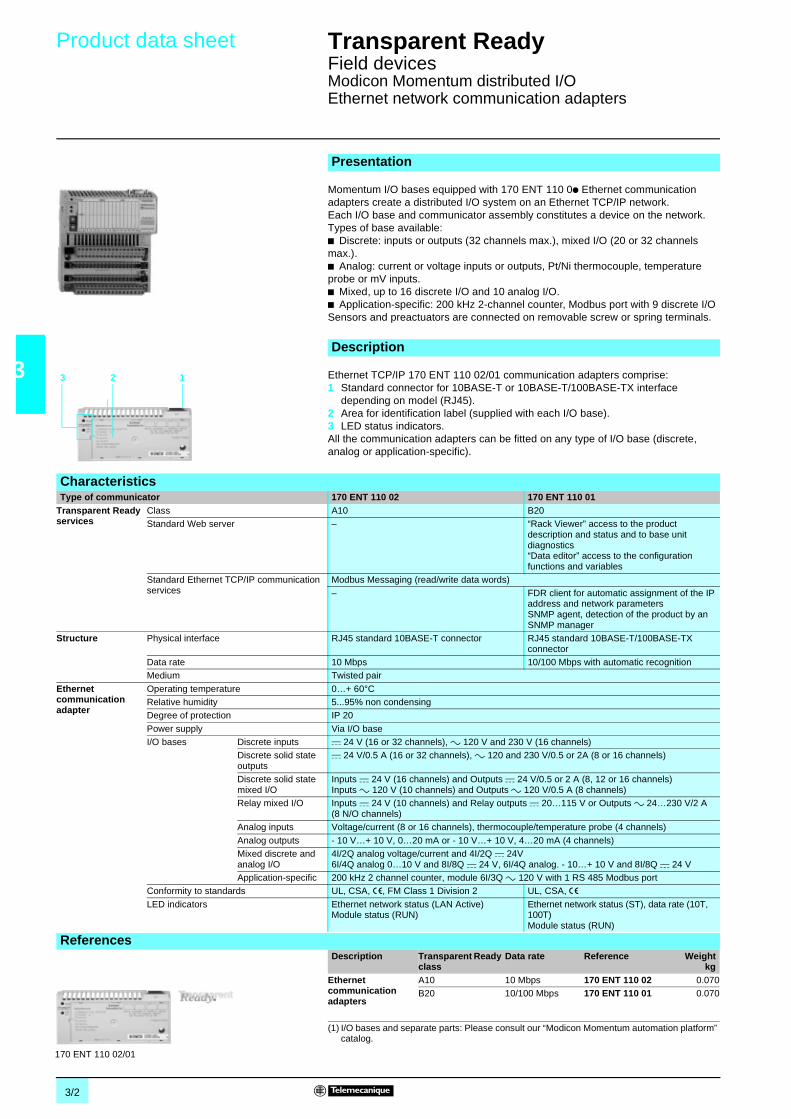
3/2
3
Product data sheet Transparent Ready 0
Field devicesModicon Momentum distributed I/OEthernet network communication adapters
Momentum I/O bases equipped with 170 ENT 110 0p Ethernet communicationadapters create a distributed I/O system on an Ethernet TCP/IP network.Each I/O base and communicator assembly constitutes a device on the network.Types of base available:b Discrete: inputs or outputs (32 channels max.), mixed I/O (20 or 32 channelsmax.).b Analog: current or voltage inputs or outputs, Pt/Ni thermocouple, temperatureprobe or mV inputs.b Mixed, up to 16 discrete I/O and 10 analog I/O.b Application-specific: 200 kHz 2-channel counter, Modbus port with 9 discrete I/OSensors and preactuators are connected on removable screw or spring terminals.
Ethernet TCP/IP 170 ENT 110 02/01 communication adapters comprise:1 Standard connector for 10BASE-T or 10BASE-T/100BASE-TX interface
depending on model (RJ45).2 Area for identification label (supplied with each I/O base).3 LED status indicators.All the communication adapters can be fitted on any type of I/O base (discrete,analog or application-specific).
Presentation
Description
3 2 1
CharacteristicsType of communicator 170 ENT 110 02 170 ENT 110 01
Transparent Readyservices
Class A10 B20Standard Web server – “Rack Viewer” access to the product
description and status and to base unitdiagnostics“Data editor” access to the configurationfunctions and variables
Standard Ethernet TCP/IP communicationservices
Modbus Messaging (read/write data words)
– FDR client for automatic assignment of the IPaddress and network parametersSNMP agent, detection of the product by anSNMP manager
Structure Physical interface RJ45 standard 10BASE-T connector RJ45 standard 10BASE-T/100BASE-TXconnector
Data rate 10 Mbps 10/100 Mbps with automatic recognitionMedium Twisted pair
Ethernetcommunicationadapter
Operating temperature 0…+ 60°CRelative humidity 5...95% non condensingDegree of protection IP 20
Power supply Via I/O baseI/O bases Discrete inputs c 24 V (16 or 32 channels), a 120 V and 230 V (16 channels)
Discrete solid stateoutputs
c 24 V/0.5 A (16 or 32 channels), a 120 and 230 V/0.5 or 2A (8 or 16 channels)
Discrete solid statemixed I/O
Inputs c 24 V (16 channels) and Outputs c 24 V/0.5 or 2 A (8, 12 or 16 channels)Inputs a 120 V (10 channels) and Outputs a 120 V/0.5 A (8 channels)
Relay mixed I/O Inputs c 24 V (10 channels) and Relay outputs c 20…115 V or Outputs a 24…230 V/2 A(8 N/O channels)
Analog inputs Voltage/current (8 or 16 channels), thermocouple/temperature probe (4 channels)
Analog outputs - 10 V…+ 10 V, 0…20 mA or - 10 V…+ 10 V, 4…20 mA (4 channels)Mixed discrete andanalog I/O
4I/2Q analog voltage/current and 4I/2Q c 24V6I/4Q analog 0…10 V and 8I/8Q c 24 V, 6I/4Q analog. - 10…+ 10 V and 8I/8Q c 24 V
Application-specific 200 kHz 2 channel counter, module 6I/3Q a 120 V with 1 RS 485 Modbus portConformity to standards UL, CSA, e, FM Class 1 Division 2 UL, CSA, eLED indicators Ethernet network status (LAN Active)
Module status (RUN)Ethernet network status (ST), data rate (10T,100T)Module status (RUN)
ReferencesDescription Transparent Ready
classData rate Reference Weight
kgEthernetcommunicationadapters
A10 10 Mbps 170 ENT 110 02 0.070B20 10/100 Mbps 170 ENT 110 01 0.070
(1) I/O bases and separate parts: Please consult our “Modicon Momentum automation platform”catalog.
170 ENT 110 02/01

3/3
3
Product data sheet Transparent Ready 0
Field devicesAdvantys STB distributed I/O
The Advantys STB distributed I/O solution is an open, modular I/O system. It can beused to design industrial automation islands managed by a master controllerconnected to various buses and networks, including Ethernet TCP/IP. Each islandcomprises a set of modules mounted on a DIN rail to make up one or more segmentsin which the power supplies (logic c 5 V, sensors and preactuators c 24 V ora 115/230 V) are distributed automatically. The Advantys STB I/O family can bedivided into 2 groups of modules:b Standard range: comprehensive offer with configurable parameters.b Basic range: just enough offer but (without parameting) with fewer functions andnon-configurable modules.Sensors and preactuators are connected on removable screw or spring terminals.The Advantys configuration software is used to set the parameters of the numerousI/O module functions (logic of each channel, behavior in the event of a short-circuitor overload, fallback position, reflex functions, etc)
The STB NIP 2212 Ethernet TCP/IP network interface module has the following onthe front panel:1 A standard connector for 10BASE-T interface (RJ45).2 Two rotary selector switches for addressing nodes on the bus or the network.3 A c 24 V external power supply connector for the removable screw-type
(STB XTS 1120) or spring-type (STB XTS 2120) terminals.4 An LED display block.5 A screw for unlocking the module from the DIN rail.6 A slot for an STB XMP 4440 removable memory card.7 Cover for access to: a port for connecting the island setup and configuration PC
or an HMI terminal (read/write data), and the Reset button.On the right-hand side panel:A bus connector for connecting (via base units) to the power distribution module andto the I/O modules (max. 32 modules on 7 segments).
Presentation
Description
3
2
1 4
56
7
CharacteristicsTransparent Readyservices
Class B20Standard Web server “Rack Viewer” access to the product description and status and to the island diagnostics
“Data editor” access to the configuration functions and variablesEthernet TCP/IP communicationmanagement service
Modbus messaging (read/write data words)FDR client for automatic assignment of the IP address and network parametersSNMP agent, detection of the product by an SNMP manager
Structure Physical interface RJ45 standard 10BASE-T connectorData rate 10 MbpsMedium Twisted pair
Ethernetcommunicationadapter
Operating temperature 0…+ 60°C without deratingRelative humidity 95% non condensing at 60°CDegree of protection IP 20
Power supply c 24 V (limits c 19.2…30 V), 750 mA maxiMax. number of I/O modules 32 per islandNumber of segments 1 primary and 6 extensions (on 15 m maxi)
I/O modules(standard et basic)
Discrete inputs c 24 V (2, 4, 6 or 16 channels), a 115 V and 230 V (2 channels)Discrete solid stateoutputs
c 24 V/0.5 A (2, 4, 6 or 16 channels), c 24 V/2 A (2 channels), a 115…230 V/2 A (2 channels)
Relay outputs c 24 V or a 115…230 V 2 “C/O”/2 A, 2 “N/C” + “N/O”/7AAnalog inputs - 10 V…+ 10 V, 0…20 mA, multi-range (2 channels)
Analog outputs - 10 V…+ 10 V, 0…20 mA (2 channels)Application-specific Tego Power 8 motor starters (16 inputs), TeSys model U 4 controller-starters (12 inputs)
40 kHz 1 channel counter
Conformity to standards IEC/EN 61131-2, UL 508, CSA 1010-1, FM Class 1 Division 2, eMarine classification: ABS, BV, DNV, GL, LR and RINA
LED indicators Ethernet network status (10T ACT, LAN ST)Module and island status (POWER, RUN, ERROR and TEST)
ReferencesDescription Use Reference Weight
kgEthernet “NIM” networkinterface modulesClass B20
c 24 V power supply STB NIP 2212 0.130
Removable power supplyterminals (pack of 10)
Screw STB XTS 1120 0.003Spring STB XTS 2120 0.003
32 Kb removable memory card Application memory backup STX XMP 4440 –
(1) Power distribution modules, I/O modules, bases, configuration software and separate parts:Please consult our “Advantys STB I/O, the open solution” catalog.STB NIP 2212

3/4
3
Product data sheet Transparent Ready 0
Field devicesAdvantys OTB distributed I/O
The Advantys OTB distributed I/O solution, which complements the Advantys STBoffer, consists of a compact system (network interface and integrated I/O) with theaddition of Twido I/O expansion modules. Each island has, on a DIN rail:b A network interface module (including Ethernet TCP/IP) with 12 c 24 V inputs,6 relay outputs and 2 solid state outputs c 24 V 0.3 A.b As an extension, up to 7 discrete or analog I/O expansion modules.This structure, created using IP 20 modules, can thus be used to manage 20 to244 I/O per island over a maximum length of 328.7 mm (height 94.5 mm).
The OTB 1E0 DM9LP Ethernet TCP/IP network interface module with integrated I/Ohas the following on the front panel:1 A pivoting door for accessing a standard to rotary switches for Ethernet address
assignment (IP by default, by DHCP server or by BOTTP server.2 An LED display block.3 Screw terminals for the c 24 V sensor power supply and for connecting the input
sensors (with 1 common).4 Screw terminals for connecting the output preactuators (with 4 commons).5 A standard connector for 10BASE-T/100BASE-TX physical interface (RJ45).On the right-hand side panel:A connector for TWD Dpp/App I/O expansion modules (7 modules max.).
Presentation
Description
1
2
3
4
5
CharacteristicsTransparent Readyservices
Class A10
Standard Web server NoneStandard Ethernet TCP/IP communicationservice
Modbus messaging (read/write data words)
Structure Physical interface RJ45 standard 10BASE-T/100BASE-TX connectorData rate 10/100 Mbps with automatic recognition
Medium Twisted pairEthernetcommunicationadapter
Operating temperature 0…+ 55°C
Relative humidity 30…95% non condensingDegree of protection IP 20Power supply c 24 V (limits c 20.4…26.4 V)
Inputs 12 inputs c 24 V, 5 and 7.7 mA, 1 common point (positive or negative logic)Connection via removable screw terminals
Outputs 6 a 230 V or c 30 V, 2 A relay outputs, 3 common points (1 x 3, 1 x 2 and 1 x 1)2 c 24 V, 0.3 A transistor outputs, 1 common point (positive logic)Connection via removable screw terminals
Conformity to standards IEC 61131-2, UL 508CSA C22.2 No. 213 (Class 1 Division 2 Groups A, B, C, D), e
LED indicators Controller status (PWR and STAT), I/O (Ip/Qp)Ethernet network status/10 or 100 Mbps data rate (10 T and 100T)
ReferencesDescription No. of discrete I/O Reference Weight
kgEthernet network interface modulec 24 V power supply
Class A10
12 a 24 V inputs6 relay outputs2 c 24 V solid stateoutputs
OTB 1E0 DM9LP 0.205
OTB 1E0 DM9LP
Discrete I/O expansion modulesNumber of channels 8 16 4 I/4 Q 16 I/8 Q
a 120 V inputs TWD DAI 8DT – – –c 24 V inputs TWD DDI 8DT TWD DDI 16DT TWD DMM 8DRT TWD DMM 24DRF2 A relay outputs TWD DRA 8RT TWD DRA 16RTc 24 V 0.3 A transistor outputs TWD DDO 8TT – – –
Analog I/O expansion moduleNumber of channels 1 2 4 8 2 I/1Q
0…10 V, 0…20 mA inputs – – TWD AMI 4LT TWD AMI 8HT –
Thermocouple/Pt temp. probe inputs – – – TWD ARI 8HT TWD ALM 3LT0…10 V, 4…20 mA outputs TWD AMO 1HT – – – TWD AMM 3HT0…10 V, 4…20 mA inputs – TWD AMI 2HT – –
+/- 0…10 V outputs – TWD AVO 2HT – –For further information, please consult our “Automation and control, automation and relay functions” catalog.

3/5
3
Product data sheet Transparent Ready 0
Field devicesLexium 17D servodrives for brushless motors
Lexium 17D digital drives provide static switching, current (or torque) regulation,speed regulation and position control for BPH, BPL or SER brushless motors. Theyare available in 7 current ratings (1.5, 3, 6, 10, 20, 40 and 70 A rms continuous).
In offline mode with integrated position indexer (simple applications that do notrequire a PLC position control module), Lexium 17D drives have a slot that can takean Ethernet TCP/IP network card. As well as the standard Ethernet connections viaswitches or hubs (for example, from the ConneXium range), this Ethernet card whichhas 2 Ethernet ports enables daisy chain connection of up to 32 Lexium 17D drives.Switches or hubs can be used to create a topology with a number of daisy chains.
The Unilink software is used for local configuration of the Ethernet parameters andEthernet, Modbus and drive diagnostics. Modbus messaging is used to access allthis information on Ethernet.
Lexium 17D drives are connected to the Ethernet TCP/IP network via theAM0 ETH 001V000 or AM0 ETH 002V000 communication card. The cards have thefollowing on the front panel:1 A 10-way Phœnix removable connector for connecting 8 configurable discrete
inputs (with AM0 ETH 002V000 card).2 LED indicators.3 A standard connector for 10BASE-T/100BASE-TX interface (RJ45).4 A standard connector for 10BASE-T/100BASE-TX interface (RJ45) for daisy
chain connection.
Presentation.
Lexium 17D
Premium
Ethernet TCP/IP Daisy Chain wiring
Description
1
2
3
4
CharacteristicsTransparent Readyservices
Class A10Standard Web server No Web serverStandard EthernetTCP/IPcommunicationservices
Modbus messaging (read/write drive parameters (240 bytes max), identification and diagnosticsSave and restore drive parameters and “Motion Tasks” in blocks via dedicated registersFDR client for local assignment of the IP addressI/O Scanning service (22 control words and 19 status words)
Structure Physical interface 2 x RJ45 standard 10BASE-T/100BASE-TX connectors (ETH1, ETH2) for daisy chainconnection
Data rate 10/100 Mbps with automatic recognitionMedium Twisted pair
Lexium 17D drives Operating temperature 0…+ 45°C, + 45…+ 55°C with derating, see our “Lexium 17D motion control” catalog
Relative humidity 85% non condensingDegree of protection IP 21Power supply 208...480 Va 3-phase
Brushless motor output Continuous/maximum current: 1.5 A/3 A to 70 A/140 A depending on the modelConformity to standards EN 50178, EN 60139-1, EN 60204, UL 508C, UL 840, CSA 22-2
Machine safety NF EN 292-1, EN954-1LED indicators Transmission/reception activity (ACT for ETH1, ACT for ETH2), communication status (STS)
ReferencesDescription For Lexium
driveNumber ofdiscrete inputs
Reference Weightkg
Communication cardsEthernet Modbus TCP/IP10/100 Mbps
Class A10
MHDA1pppN00/A00
– AM0 ETH 001 V000 r 0.180
8 AM0 ETH 002 V000 r 0.195
r Available laterAM0 ETH 002V000AM0 ETH 001V000

3/6
3
Product data sheet Transparent Ready 0
Field devicesATV 71 variable speed drives
The Altivar 71 range of variable speed drives extends across a range of motor powerratings from 0.37 kW to 500 kW with three types of power supply:b 200_240 V single-phase, from 0.37 kW to 5.5 kWb 200_240 V 3-phase, from 0.37 kW to 75 kWb 380_480 V 3-phase, from 0.75 kW to 500 kW.
Open to all industrial communication networks and featuring numerous automationsystem options, the Altivar 71 adapts effortlessly to complex sophisticated machines.Its performance levels and ease of parameter setting make it the reference productup to 500 kW. It can be connected to Ethernet Transparent Ready by an optionalcard.The Altivar 71 can be inserted in an installation’s safety system. It integrates the“Power Removal” safety function which prohibits any accidental starting of the motor.This function complies with machine standard EN 954-1 category 3, the standardgoverning electrical installations IEC/EN 61508 SIL2 and the power drive systemsstandard IEC/EN 61800-5-2.
The functionality of the Altivar 71 drive boosts performance and increases amachine’s flexibility of use across multiple applications (handling, hoisting, processmachines, textile machines, packaging, ...).
The Altivar 71 variable speed drive can integrate a maximum of three option cardssimultaneously, of which the Ethernet TCP/IP communication card. All the drivefunctions can be accessed via Modbus services: controlling, monitoring, adjustmentand configuration.1 An optionnal Ethernet TCP/IP communication card.2 A standard connector for 10BASE-T/100BASE-TX interface (RJ45).
(1) The standard Web server can be adapted or replaced by a customized Web server dependingon the requirements of the application. Knowledge of HTTP protocol and Java technology isrequired to make modifications.
(2) The periodic variables of I/O Scanning may be freely assigned according to the needs of theapplication.
Presentation
ATV 71 without graphic terminal
ATV 71 with graphic terminal
Description1
2
CharacteristicsTransparent Readyservices
Class C20Standard Web services (1) “Altivar Viewer” drive diagnostics
“Data editor” access to the configuration, adjustment and signaling functions“Altivar chart” simplified oscilloscope function“Security” configuration of passwords to access viewing and modification"Ethernet statistics” drive identification and transmission statistics
Configurable Web service Downloading user defined Web pages via FTPStandard Ethernet TCP/IP communicationservices
Modbus TCP/IP messaging(read/write registers, read device identification, diagnostics)BOOTP, DHCP (8 simultaneous Modbus TCP/IP connections), TFTP
Ethernet TCP/IP advanced communicationservices
I/O Scanning, 10 control variables and 10 monitoring variables freely configurable (2)FDR client, automatic assignment of the IP address and network parametersSNMP agent, detection of the product by an SNMP manager
Ethernet structure Physical interface RJ45 standard 10BASE-T/100BASE-TX connectorData rate 10/100 Mbps with automatic recognition
Medium Twisted pairVariable speeddrive
Operating temperature - 10…+ 50°C or - 10…+ 60°C with derating and with the control card fan kit VW3 A9 4ppRelative humidity 5...95 % without condensation or dripping water conforming to IEC 60068-2-3
Degree of protection IP 21 or IP00 (depending on model) and IP 41 on upper part (with cover plate)Output frequency range 1...1000 Hz ou 1...500 Hz depending on modelSpeed range 1...100 in open loop mode
Motor control profile withmotor
Asynchronous Flux vector control with or without sensor, voltage/frequency ration (2 or 5 pulses), ENA systemSynchronous Vector control without speed feedback
Conformity to standards IEC/EN 61800-5-1, IEC/EN 61800-3 (environments 1 and 2 categories C1 to C3,e, UL, CSA, DNV, C-Tick, NOM 117 and GOST
LED indicators 5 LEDs on the card: RX (reception), TX (transmission), FLT (collision detection),STS (IP address) and 10/100 Mbps (speed)
ReferenceDescription For drive Reference Weight
kgCommunication cardEthernet Modbus TCP/IP10/100 Mbps
Class C20
ATV 71, ATV 61 VW3 A3 310 0.300
VW3 A3 310

3/7
3
Product data sheet Transparent Ready 0
Field devicesATV 61 variable speed drives dedicated topump and fan applications
Dedicated to pump and fan applications in building and industrial segments, theAltivar 61 variable speed drives adapt effortlessly to simple catalogue machines.Its performance levels and ease of parameter setting make it the reference product.Open to all building and industrial communication networks, it can be connected toEthernet Transparent Ready by an optional card.
The Altivar 61 range of variable speed drives extends across a range of motor powerratings up to 630 kW with two types of power supply:b 200_240 V 3-phase, up to 90 kWb 380_480 V 3-phase, up to 630 kW.
The Altivar 61 integrates the numerous functions : PID regulator, automatic motoradaptation, automatic restart, sleep and wake up mode, flying mode, ...
The Altivar 61 can be inserted in an installation’s safety system. It integrates the“Power Removal” safety function which prohibits any accidental starting of the motor.This function complies with machine standard EN 954-1 category 3, the standardgoverning electrical installations IEC/EN 61508 SIL2 and the power drive systemsstandard IEC/EN 61800-5-2.
The Altivar 61 variable speed drive can integrate a maximum of three option cardssimultaneously, of which the Ethernet TCP/IP communication card. All the drivefunctions can be accessed via Modbus services: controlling, monitoring, adjustmentand configuration.1 An optionnal Ethernet TCP/IP communication card.2 A standard connector for 10BASE-T/100BASE-TX interface (RJ45)..
(1) The standard Web server can be adapted or replaced by a customized Web server dependingon the requirements of the application. Knowledge of HTTP protocol and Java technology isrequired to make modifications.
(2) The periodic variables of I/O Scanning may be freely assigned according to the needs of theapplication.
Presentation
ATV 61 without graphic terminal
ATV 61 with graphic terminal
Description1
2
CharacteristicsTransparent Readyservices
Class C20Standard Web services (1) “Altivar Viewer” drive diagnostics
“Data editor” access to the configuration, adjustment and signaling functions“Altivar chart” simplified ocsilloscope function“Security” configuration of passwords to access viewing and modification"Ethernet statistics” drive identification and transmission statistics
Configurable Web service Downloading user defined Web pages by FTPStandard Ethernet TCP/IP communicationservices
Modbus TCP/IP messaging(read/write registers, read device identification, diagnostics)BOOTP, DHCP (8 simultaneous Modbus TCP/IP connections), TFTP
Ethernet TCP/IP advanced communicationservices
I/O Scanning, 10 control variables and 10 monitoring variables freely configurable (2)FDR client, automatic assignment of the IP address and network parametersSNMP agent, detection of the product by an SNMP manager
Structure Physical interface RJ45 standard 10BASE-T/100BASE-TX connectorData rate 10/100 Mbps with automatic recognition
Medium Twisted pairDrive Operating temperature - 10…+ 50°C or - 10…+ 60°C with derating and with the cpntrol card fan kit VW3 A9 4pp
Relative humidity 5...95 % without condensation or dripping water conforming to IEC 60068-2-3
Degree of protection IP 21 or IP00 (depending on model) and IP 41 on upper part (with cover plate)Output frequency range 1...1000 Hz ou 1...500 Hz depending on modelSpeed range 1...100 in open loop mode
Motor control profile with asynch. motor Flux vector control without sensor, voltage/freqency ration (2 or 5 pulses), ENA systemConformity to standards IEC/EN 61800-5-1, IEC/EN 61800-3 (environments 1 and 2 categories C1 to C3,
e, UL, CSA, DNV, C-Tick, NOM 117 and GOSTLED indicators 5 LEDs on the card: RX (reception), TX (transmission), FLT (collosion detection),
STS (IP address) and 10/100 Mbps (speed)
ReferenceDescription For drive Reference Weight
kgCommunication cardEthernet Modbus TCP/IP10/100 Mbps
Class C20
ATV 71, ATV 61 VW3 A3 310 0.300
VW3 A3 310

3/8
3
Product data sheet Transparent Ready 0
Field devicesInductel identification systemEthernet read/write station
Inductive technology is based on the use of a medium frequency electromagneticsignal (carrier), for contactless transmission between two electronic devices. It isused for identifying products during manufacture and improving the management ofproduct-related data flows.
The system consists of:b Updatable code badges, with decentralized memory (ferroelectric memory orEEPROM), accessible in read and write mode for use with the product to beidentified.b The read/write station with remote antenna, a bidirectional communication devicethat manages the data transmitted between the badge and the processor via theEthernet TCP/IP network.
The XGKS 1715503 read/write station is in the form of a dust and damp proof metalbox comprising:1 A 5-way female M12 connector for connection to the antenna (XGLA... or
XGPA…).2 A display block consisting of 5 LEDs indicating the station status.3 A removable cover for accessing the station configuration switches.4 A 20UNF 3 1/2" 3-pin male connector for connecting the c 24 V station power
supply (female connector to be ordered separately).5 An IP 65 shielded base for connection to the Ethernet network.The special connector supplied with the station is used to form a dust and damp proofconnection using any standard RJ45 cable.
This station (210 x 60 x 235), is fixed onto a frame or panel using 4 screws(4 x 8 holes).
Presentation
DATA DATA
DATA DATA
DATA DATA
DATA DATA
DATA DATA
DATA DATA
DATA DATA
DATA DATA
Read/write station with antenna and updatable code badge
Description1
2
3
45
CharacteristicsTransparent Readyservices
Class B10Standard Web server “Inductel Viewer” access to the product description, status and diagnostics
“Data editor” access to the configuration functions and variablesStandard Ethernet TCP/IP communicationservice
Modbus messaging (read/write I/O words)
Structure Physical interface 10BASE-T/100BASE-TX, standard RJ45 connector with IP 65 shielded baseData rate 10/100 Mbps with automatic recognition
Medium Double twisted pairNetwork interfacemodule controller
Operating temperature 0…+ 50°CRelative humidity 30…95% non condensing
Degree of protection IP 65Power supply c 24 V (limits c 21…29 V)External antenna 5-way female M12 connector (antenna/station link 2 m max.)
Communication Requests Modbus TCP/IP 124 words max.Data rate 500 words/s max. depending on antenna used
Conformity to standards UL, eElectromagnetic interference, level 3 according to IEC 61000-4-2/4-3/4-3
LED indicators On (green), badge present (yellow), badge and communication port faults (red)Ethernet network activity (RUN, green), collision detection (COL, red), diagnostics (STS,yellow) and fault (ERR, red)
ReferencesDescription Integrated Ethernet
portReference Weight
kgRead/write stationc 24 V power supply
Class B10
10/100 Mbps XGK S1715503 1.120
- Antennae, updatable code badges, connection accessories: please consult our “Inductiveidentification system” catalog.- IP 67 switch and cables, see page 8/6.
XGK S1715503

3/9
3
Product data sheet Transparent Ready 0
Field devicesOsitrack identification system
This unit is used to connect up to 3 XGC S RFiD compact stations to an EthernetTCP/IP network.Data is exchanged with the Ositrack stations using the Modbus TCP/IP protocol.
As a server on the Ethernet network, the cable connector can receive and respondto messages.This data exchange enables the Ethernet TCP/IP network to access certain Ositrackstation functions, such as:b Reading/writing tagsb Control and commandb Monitoringb Diagnostics.
The XGS Z33ETH cable connector is a dust and damp proof metal box comprising:1 Signaling LEDs relating to the Ethernet TCP/IP network.2 An M12 D-coded connector for connection to the Ethernet TCP/IP network.3 An M12 A-coded connector, for connecting the 24 Vc power supply.4 3 x M12 A-coded connectors for connecting Ositrack XGC S compact stations.
This cable connector, dimensions 237 x 120 x 60 mm, is attached via the rear using2 screws (4 mm).
Presentation
Description
1
22
3
4
CharacteristicsTransparent Readyservices
Class A10Standard Web server No Web server
Standard Ethernet TCP/IP communicationservice
Modbus messaging (read/write I/O words)
Structure Physical interface 10BASE-T/100BASE-T XData rate 10/100 Mbps with automatic recognitionMedium Ethernet cable with M12 connection (TCS EN1M3pp)
XGS cableconnector
Operating temperature - 25…+ 55°C
Relative humidity 30…95% non condensingDegree of protection IP 65Power supply c 24 V (limits c 21…29 V)
Connecting XGC S stations 5-way female M12 connectorCommunication Requests Modbus TCP/IP 124 words max.
Speed 2 Kbytes/s max. depending on associated tags
Conformity to standards UL, eElectromagnetic interference, level 3 according to IEC 61000 and EN 55022
LED indicators Ethernet network activity (RUN, green), collision detection (COL, red), diagnostics (STS,yellow), fault (ERR, red) and 24 Vc power supply (yellow)
ReferenceDescription Integrated Ethernet
portReference Weight
kgEthernet cable connector (for 3 XGCS compact stations)24 Vc power supply
Class A10
10/100 Mbps XGK Z33ETH r 0.830
- Stations, updatable code badges, connection accessories: please consult our “Inductiveidentification system” catalog.- IP 67 switch and cables, see page 8/6.
r Available later
XGK Z33ETH

/0

4/1
4
Contents 4 - Ethernet gateway products 0
4 - Product data sheets
b TSX ETG 100 Ethernet/Modbus gateway . . . . . . . . . . . . . . . . . . . . . . . page 4/2
b TSX ETG 1000/1010 Web FactoryCast Gateways . . . . . . . . . . . . . . . . page 4/3
b 174 CEV 300 20/CEV 200 40 Ethernet/Modbus-Modbus Plus gateways page 4/4

4/2
4
Product data sheet Transparent Ready 0
Ethernet gatewaysEthernet/Modbus gateway
TSX ETG 100 gateway provides a simple and low-cost means of integrating anyexisting Modbus serial RTU device, installation or automation island in an EthernetTCP/IP network infrastructure.The gateway is able to make the serial Modbus devices directly accessible to highlevel application in real time (management, SCADA).
Modbus serial devices can be Twido controller, Compact/Momentum/Premium/Quantum PLCs, Altivar variable speed drives, Altistart starters, Magelisterminals or any other products compatible withe the Modbus standards.
TSX ETG 100 gateway is an IP 30 box, mounted on DIN rail.
1 A screw terminal for connecting the c 24 V power supply.2 A standard RJ45 connector for 10BASE-T/100BASE-TX interface.3 A RJ45 connector for Modbus RS 232 sérial link.4 A micro switches for 2 or 4-wire RS 485 serial link configuration.5 A 5-way removable terminal block for Modbus RS 485 serial link .6 Seven LED indicators for Ethernet communication (LK, RX, TX, 100), and serial
link communication (RS485, RX, TX).7 A LED indicator for c 24 V power supply and Reset button.
r Available later
Presentation
Description
12
345
6
7
CharacteristicsType of gateway TSX ETG 100
Transparent Readyservices
Class B10Standard Webservices
Configuration Predefined Web pagesRead/Write Acces to connected products list, reading of Modbus devices registers
Diagnostic Via predefined Web pages : diagnostic on Ethernet and Modbus linksEthernet TCP/IPcommunicationmanagementservices
Modbus messaging Read/Write Modbus registers of connected devices
SNMP SNMP Agent, device administration with a SNMP managerBOOTP protocol FDR Client (replacement of defective product)Security Miniature firewall on-board (IP address filtering) and password protection
Ethernetconnectivity
Physical interface 10BASE-T/100BASE-TX (RJ45)Data rate 10/100 Mbps with automatic recognitionMedium Twisted pair
Modbus connectivity Type of port RS 485 (2 or 4-wire) or RS 232Protocol Modbus (RTU and ASCII)Maxi transmission speed 38,4 Kbps (RS 485), 57,6 Kbps (RS 232)
Number of devices 32 max.Other characteristics Operating temperature 0...+ 60 °C
Relative humidity 5…95% non condensing at 40 °C
Degree of protection IP 30Dimensions (L x H x P) 72 x 81 x 76 mm, mounting on symmetrical DIN railPower supply c 24 V, 4 W or by power supply device PoE (Power Over Ethernet - IEEE 802.3af)
Conformity to standards UL, cUL (conforming to CSA C22-2 no. 14-M91), UL508, eEnvironmental resistance EN 61000-6-2, EN 61000-4-2/3/4/5/6/8, EN 55022/FCC class A
ReferencesDescription Fonctions References Weight
kgModbus Ethernetgateway/router
Class B 10
Twido, Compact, Momentum, TSX Micro,Altivar, Altistart, Magelis, ...All products compatible with Modbusstandard
TSX ETG 100 r –
Kit for configuration Allows gateway configuration throughEthernet or RS 232 port.Comprises RJ45/SUB-D 9 contactsadaptator and a CAT5 twisted pair cable,3 m length
TCS EAK 0100 r –
PoE power supply(conform toIEEE 802.3af)
Allows gateway power supply throughEthernet CAT5 cable. Daisy chain powersupply connection. Include power supplycable (Australia, Europa, UK and USA)
TCS EAQ 0100 r –TSX ETG 100 TCSEAQ

4/3
4
Product data sheet Transparent Ready 0
Ethernet gatewaysWeb FactoryCast Gateway
FactoryCast Gateway is a new offer of “all in one” intelligent Web gatewaysintegrating, in a standalone compact unit:b All the TCP/IP network communication and serial link (Modbus or Uni-Telway)interfaces.b An RAS remote access (1)/IP Router function.b A customizable Web server .TSX ETG 1000/1010 gateways are a low-cost response to the need to integrateserial link installations in an existing Ethernet TCP/IP infrastructure as well asrequirements for remote access services including remote diagnostics, remotemaintenance, remote monitoring and remote control.
TSX ETG 1000/1010 FactoryCast Gateways feature, on the front panel:1 Three LEDs indicating the gateway status (RUN, ERR, Ethernet)2 The module MAC address (default factory-set address)3 A mini-DIN connector for connection to the terminal port (marked TER)4 An RJ45 connector for the serial link (Modbus or Uni-Telway) (marked RS 485)5 A standard RJ45 connector for connection to the Ethernet TCP/IP network
(marked ETHERNET)6 A 9-way male SUB-D connector for the RS 232 serial link (marked
Modem RS 232)7 A screw terminal for connecting the 24 Vc external power supply8 A support plate for fixing the module to a DIN rail or an AM1-PA pre-slotted plate
r Available later
Presentation
Description1
4
5
6
7
8
23
TSX ETG 1000 TSX ETG 1010
CharacteristicsWeb gateway module FactoryCast Gateway TSX ETG 1000 TSX ETG 1010
TransparentReady servicesClass C20
Gateway/router function Ethernet TCP/IP gateway to Modbus, modemto Modbus and modem to Ethernet TCP/IP withIP routing
Ethernet TCP/IP gateway to Uni-Telway,modem to Uni-Telway and modem to EthernetTCP/IP with IP routing
Routing of the I/O Scanning serviceProtocols Serial Modbus master Uni-Telway slave
TCP/IP Modbus TCP Uni-TE TCP and/or Modbus TCPStandard Webservices
Configuration Via predefined Web pagesDiagnostic Via predefined Web pages: Diagnostics on Ethernet link, serial link, modem link; and
diagnostics on e-mail and FDR servicesRead/write Data editor, “ready-to-use” Web pages: Access to connected device registers
Configurable Web services HTTP server (8 MB of Flash memory available)Hosting of animated Web pages created by the user and all documents (doc, pdf, etc.)Library of graphic objects (Java applet) with Wizard utility for FrontPage
File upload/download via FTPE-mail service Alarm notification by e-mail (via remote SMTP server)Ethernet TCP/IPadvancedcommunicationservices
BootP/DHCP protocol Automatic assignment of IP address, FDR client (replacement of defective product)
SNMP SNMP agent, administration of the device by an SNMP managerSecurity Miniature firewall on-board (IP address filtering) and password protection
Connectivity Ethernet TCP/IP Physical interface RJ45 standard 10BASE-T/100BASE-TX connectorData rate 10/100 Mbps with automatic recognitionMedium Twisted pairs
Modem Physical interface RS 232C link, half- or full-duplex, 57 kbps, 9-way SUB-D connectorPPP protocol (incoming and outgoing calls), PAP authentication protocol
Services Remote access via RAS compatible with RTC, GSM, VPN modemSerial link Physical interface Modbus RS 485 link, max. 115 kbps, standard
RJ45 connectorUni-Telway RS 485 link, max. 19.2 kbps,standard RJ45 connector
No. of devices 32 max.Characteristics Operating temperature 0 to + 60°C
Relative humidity 10 to 95% non condensing during operationDegree of protection IP 20Power supply c 24 V (limits c 19.2 to 30 V), 100 mA
Conformity to standards ISO/IEC 8802-3, ANSI/IEEE Std 802.3, EN 61000-6-4, EN 55011 Class A,IEC/EN 61131-2, UL 508, CSA C22.2 No. 142, CSA C22.2 No. 213 Class 1 Division 2
Pending: Marine Marchande certificationsLED indicators Modbus activity (RUN Modbus) Uni-Telway activity (RUN/UTW)
Ethernet activity (ETHERNET), gateway error (ERR)
ReferencesDesignation Routing Reference Weight
kgWeb FactoryCast Gatewaygateways/routersClass C20
Ethernet / Modbus RTU TSX ETG 1000 0,280Ethernet / Uni-Telway TSX ETG 1010 r 0,280
TSX ETG 1000 TSX ETG 1010

4/4
4
Product data sheet Transparent Ready 0
Ethernet gatewaysEthernet/Modbus - Modbus Plus
The 174 CEV ConneXium communication gateways are used for interconnecting thefollowing:b Modbus/Ethernet TCP/IP for 174 CEV 300 20b Modbus Plus/Ethernet TCP/IP for 174 CEV 200 40by providing multiple ports to adapt to the different architecture.
Presentation
Characteristics
Type of gateway 174 CEV 300 20 174 CEV 200 40TransparentReadyservices
Class A10 B10Standard Web services Configuration – Predefined Web pages
Read/Write – Acces to connected products list, readind ofModbus Plus devices registers
Diagnostic – Via predefined Web pages : diagnostic onEthernet and Modbus Plus links
Standard Ethernet TCP/IP communicationservices
Modbus TCP messaging SNMP Agent
Functions Communication gateway Ethernet/Modbus (many-to-many Modbus) Ethernet/Modbus Plus(many-to-many Modbus Plus)
Interface for programming Ethernet/Modbus Ethernet/Modbus PlusModbus SL (RS 232/RS 485 serial link) RTU/ASCII frame
Data rate 0.3 K…115.2 Kbps–
Modbus Plus (RS 485 network) – Token bus, HDLC synchronous modeData rate 1 Mbps
Configuration Local or remote by Telnet in hyper terminalmode
Local or remote (1)
Interfaces Ethernet TCP/IP port Type 1 x 10BASE-T/100BASE-TX 1 x 10BASE-T/100BASE-TX
Shielded connectors RJ45Medium Shielded twisted pairMax. distances 100 m (327 ft)
Serial port Type 1 x Modbus SL 1 x Modbus PlusShielded connectors RJ45 9-way SUB-D connectorMedium Shielded twisted pair Shielded twisted pair (single or double)
Power supply Voltage c 9…30 V,a 9 …24 V
a 110/220 V (a 93.5 V…242 V), 47…63 Hz
Power consumption 3 W 1 AOperating temperature 0…+ 60°C 0…+ 50°CRelative humidity 20…90% non condensing 10…95% non condensing
Degree of protection IP20 IP20Dimensions W x H x D mm (in) 35 x 95 x 60 (1.38 x 3.74 x 2.36) 122 x 229 x 248 (4.80 x 9.0 x 9.80)Weight kg (lbs) 0.500 (1.10) 4.260 (9.40)
Conformity to standards UL, CSA, FM 3611 Class 1 Division 2 UL 508, CSA 142, eLED indicator Activity, status, diagnostics Power
(1) Local with additional keyboard and monitor, via a dedicated screen for basic diagnostic andconfiguration. Remote, via intuitive Web pages for full configuration and diagnostic.
Reference
174 CEV 200 40174 CEV 300 20
Description TransparentReady class
Functions References Weightkg
Ethernet/Modbusgateway
A10 - 1 Ethernet port,10BASE-T/100BASE-TX- 1 Modbus serial link port
174 CEV 300 20 0,500
Ethernet/Modbus Plusgateway/router
B10 - 1 Ethernet port,10BASE-T/100BASE-TX- 1 Modbus Plus port
174 CEV 200 40 4,260

0/1
0
5/1
5
Contents 5 - Electrical Distribution products 0
5 - Product data sheets
b MV and LV protection and metering products and iMCC motors control-command
products page 5/2
v EGX 100MG gateway . . . . . . . . . . . . . . . . . . . . . . . . . . . . . . . . . . . . . page 5/2
v EGX 400MG gateway/server . . . . . . . . . . . . . . . . . . . . . . . . . . . . . . . page 5/3
b Advanced electrical circuit monitors CM 3000/CM 4000 . . . . . . . . . . . . page 5/4
b PowerLogic SMS electrical power management software . . . . . . . . . . . . page 5/5

5/2
5
Product data sheet(continued)
Transparent Ready 0
Electrical distribution productsMV and LV protection and metering productsiMCC motors control-command products
Merlin Gerin communicating electrical distribution protection and measurementproducts are ideal for integration in Transparent Ready architectures.This range includes in particular:b Sepam series 20, 40 and 80 Medium Voltage (MV) protection relays.b Masterpact Low Voltage (LV) circuit-breakers used with their Micrologic A, P or Hprotection units.b Power Logic power meters (PM), such as the PM500, PM700 and PM800, that canbe used for both MV and LV.b The advanced Power Logic Circuit Monitors (CM), such as the CM3000 andCM4000.b The controllers starters TeSys Model U (intelligent motor starters).b The Altivar variable speed drives.
These products are connected to Ethernet via the EGX 100 MG gateway that isgenerally mutualized for a number of electrical distribution and motors controlproducts:
1 A screw terminal for connecting the c 24 V power supply.2 A standard RJ45 connector for 10BASE-T/100BASE-TX interface.3 A RJ45 connector for Modbus RS 232 sérial link.4 A micro switches for 2 or 4-wire RS 485 serial link configuration.5 A 5-way removable terminal block for Modbus RS 485 serial link .6 Seven LED indicators for Ethernet communication (LK, RX, TX, 100), and serial
link communication (RS485, RX, TX).7 A LED indicator for c 24 V power supply and Reset button.
Presentation
Masterpact
Sepam
PowerLogic PM TeSysmodel U
Altivar 71 Description of the EGX 100MG gateway
12
345
6
7
CharacteristicsType of communicator EGX 100MG
Transparent Readyservices
Class B10Standard Webservices
Configuration Predefined Web pages
Read/Write Acces to connected products list, readind of Modbus devices registersDiagnostic Via predefined Web pages : diagnostic on Ethernet and Modbus links
Ethernet TCP/IPcommunicationmanagementservices
Modbus messaging Read/Write Modbus registers of connected devices
SNMP SNMP Agent, device administration with a SNMP managerBOOTP protocol FDR Client (replacement of defective product)Security Miniature firewall on-board (IP address filtering) and password protection
Ethernetconnectivity
Physical interface 10BASE-T/100BASE-TX (RJ45)Data rate 10/100 Mbit/s with automatic recognitionMedium Twisted pair
Modbus connectivity Type of port RS 485 (2 or 4-wire) or RS 232Protocol Modbus (RTU and ASCII), PowerLogic - RNIM (Sy/Max)Maxi transmission speed 38,4 Kbps (RS 485), 57,6 Kbps (RS 232)
Number of devices 32 max.Other characteristics Operating temperature - 25 °C to + 70 °C
Relative humidity 5…95% non condensing at 40 °C
Degree of protection IP 30Dimensions (W x H x D) 72 x 81 x 76 mm, mounting on symmetrical DIN railPower supply c 24 V, 4 W or by power supply device PoE (Power Over Ethernet - IEEE 802.3af)
Conformity to standards UL, cUL (conforming to CSA C22-2 no. 14-M91), UL508, eEnvironmental resistance EN 61000-6-2, EN 61000-4-2/3/4/5/6/8, EN 55022/FCC class A
ReferencesDescription Fonctions References Weight
kgModbus Ethernetgateway/router
Class B 10
Twido, Compact, Momentum, TSX Micro,Altivar, Altistart, Magelis, ...All products compatible with Modbusstandard
EGX 100MGr –
Kit for configuration Allows gateway configuration throughEthernet or RS 232 port.Comprises RJ45/SUB-D 9 contactsadaptator and a CAT5 twisted pair cable,3 m length
RJ45 CFG r –
PoE power supply(conform toIEEE 802.3af)
Allows gateway power supply throughEthernet CAT5 cable. Daisy chain powersupply connection. Include power supplycable (Australia, Europa, UK and USA)
PSP OE r –
TSX EGX 100 TCSEAQ
r Available later

5/3
5
Product data sheet(continued)
Transparent Ready 0
Electrical distribution productsMV and LV protection and metering productsiMCC motors control-command products
Merlin Gerin communicating products can be connected to Ethernet via theEGX 400MG gateway/server, that is generally mutualized for a number of electricaldistribution and motors control products.
The EGX 400MG gateway allows transparent connectivity on Ethernet and profitsfrom Web services associated to products listed above, for easy monitoring of theelectric network.The EGX 400MG gateway also provides Modbus serial link/Modbus TCP/IP gatewayservices for all Modbus products. It can also take a Modbus master product on oneof its ports (configured for this purpose) that will then have access to the Modbusproducts on the other port.
The EGX 400MG gateway is specifically designed to withstand harsh thermal orelectrical environments.
The front side1 A screw terminal for connecting the c 24 V power supply.2 Ethernet indication LEDs.3 A 10/100BASE-TX port for connection to Ethernet via an RJ45 connector.4 A 100BASE-FX port for connection to Ethernet via an optic cUL (complying with
CSA C22-2 no. 14-M91).5 A terminal block for RS 485 Modbus serial link (COM1).6 COM1 indication LEDs.7 A terminal block for RS 485 Modbus serial link (COM2).8 COM2 indication LEDs.9 Mini-switches for setup of the two configuration ports.10 A SUB-D 9-way connector for connection to the RS 232 serial link.
(1) e.g., maximum recording during 38 days, 6 informations from 32 products, every 15 minutes(possible every 5, 30 or 60 minutes).
Presentation of the EGX 400MG gateway/server
Description of the EGX 400MG gateway/server
1 2 3 4 5 6 7 8 9 10
CharacteristicsType of communicator EGX 400MG
Transparent Readyservices
Class C10Standard Web server Configuration of the gateway communication functions
Monitoring/diagnostics pages associated with the products connected downstreamHistory with graphical display (1). Exports with CSV format (Comma Separated Values) viaE-mail, FTP or Microsoft Web Query.
Configurable Web server Summary Web pages, and ability to record variables (16 Mo possible). Web pages are createdusing the WPG tool (Web Page Generator), provided with the gateway.
Ethernet TCP/IP communicationmanagement service
Modbus messaging
SNMP agent, SNTP time synchronization, HTTP protocol, FTP file sharingEthernet connection Physical interface 10BASE-T/100BASE-TX (RJ45)
100BASE-FX
Medium Twisted pair or optical fiberModbus connections Number of ports 2
Types of port Port 1, RS 485 (2 or 4-wire)
Port 2, RS 232 or RS 485 (2 or 4-wire)Protocol ModbusTransmission speed 38.4 Kbps
Recommended max. number of devices 32 per port, ie. 64 in totalOther characteristics Operating temperature - 30°C to + 80°C
Relative humidity 5…95% non condensing at 40°C
Dimension (W x H x D) 201 x 28 x 123 mmPower supply c 24 V (a 100-240 V socket adapter supplied), 8 WConformity to standards cUL (conforming to CSA C22-2 no. 14-M91), UL508, eEnvironmental resistance EN 61000-6-2, EN 61000-4-2/3/4/5/8/11, EN 55022/FCC class AMounting On symmetrical or asymmetrical DIN rail
ReferencesDescription Fonctions References Weight
kgModbus Ethernetgateway/server
Class C 10
Sepam, Masterpact/Micrologic, PM, CM,TeSys model U, ATV or other Modbusproducts
EGX 400MG 0.700
WPG software Web pages creation Provided with the gateway

5/4
5
Transparent Ready 0
Electrical distribution productsAdvanced electrical circuit monitorsCM 3000/CM 4000
CM 3000 and 4000 Circuit Monitors are high-performance monitoring units thatprovide a large number of possibilities.Installed on the incoming feeder, on the Medium Voltage (MV) or Low Voltage (LV)switchboard incoming supply or on sensitive outgoing feeder, the Circuit Monitorsrecord the electrical parameters of the installation. They provide relevant informationfor controlling costs, improving power quality and minimizing production downtime.They offer the possibility of detailed recording of the conditions of any detectedinterference.Depending on the model and the options, they also perform the following:b Detection and recording of voltage dips and jumps which cause productionstoppages on some sensitive processes.b Detection and recording of voltage transients: acquisition of currents and voltagesadapted to the transients detection: 5 MHz voltage sampling .b Precise (1 ms) time synchronization by GPS.
They provide current and voltage measurement precisions from 0.04% to 0.1%.
These products are connected to Ethernet via their ECC21 option card.This card also provides an integrated Web gateway/server function to Modbus onEthernet TCP/IP for Modbus Serial Link communicating products connecteddownstream:
1 ECC 21 Ethernet option card for Circuit Monitor.2 A standard connector for 10BASE-T/100BASE-TX interface (RJ45) with, for the
EGX 400, a 100BASE-FX connector.3 Modbus serial port for gateway/server function for connecting Modbus products
downstream.
The gateway/server function provided by the ECC 21 card is similar to that of theEGX server, but with a lower capacity.
Presentation
CM 3000/CM 4000
Description1
3
2
CharacteristicsType of communicator ECC 21
Transparent Readyservices
Class C10Configurable Web server Configuration of the CM communication functions and the Modbus TCP/IP gateway function
6 monitoring pages, 5 of which are customizableOne page displays details of the electrical values of the host CMThe other 5 Web pages (created using the WPG tool) can provide displays of the main electricalvalues of the Modbus products connected downstream
Ethernet TCP/IP standard communicationmanagement service
Modbus messagingSNMP agent, SNTP time synchronization, SMTP e-mail notification (transmission according toalarms), HTTP protocol, FTP file sharing
Ethernet connection Physical interface 10BASE-T/100BASE-TX (RJ45)
100BASE-FXMedium Twisted pair or optical fiber
Modbus connections Number of ports 1
Type of ports RS 485 (2 or 4-wire)Protocol ModbusTransmission speed 38.4 Kbps
Recommended max. number of devices 32Other characteristics Operating temperature - 25°C to + 70°C
Relative humidity 5…95% non condensing at 40°C
Conformity to standards e, UL508Environmental resistance EN 61000-6-2, EN 61000-4-2/3/4/5/8/11, EN 55022/FCC class A
ReferencesDescription For Circuit Monitor
metering unitReference Weight
kgEthernet option card
Class C10
CM3000CM4000
ECC21 –
ECC 21

5/5
5
Product data sheet Transparent Ready 0
Electrical distribution productsPowerLogic SMS electrical power managementsoftware
PowerLogic SMS software is a set of software tools specially designed to help theuser of an electrical network to control this network and reduce the costs connectedwith electrical power.
The tools are deliberately simple to configure, and incorporate the library of electricaldistribution communicating components, such as Power Meter, Circuit Monitor,Masterpact or Sepam, as standard. They are also open, so that they can handle anytype of Transparent Ready product (using Modbus TCP/IP messaging).
The software offers a large number of pre-defined screens, enabling users to quicklyaccess the electrical data they require. These screens can also be customized.
Using such a tool the user can:b Ascertain the status of his network.b View the load curves.b Optimize his contract with his energy supplier.b Use submetering and thus accurately re-allocate energy costs.b Optimize his investment.b Monitor electricity quality for optimum operation of the network and the processbeing supplied.
The SMS software range covers various needs according to functional requirementsand type of electrical installation.
(1) At the end of the reference, add ENG for English, FRA for French ou ESP for Spanish.
Presentation
Description
CharacteristicsType PowerLogic SMS, “electrical engineer” supervisory software
Compatibility All Merlin Gerin and SquareD electrical distribution products and other Transparent Readyproducts
Operating system Windows 98, Windows 2000 and Windows XP
Type of software license Single product Multi-productReference(1) Electrical Measurement oriented – PMX 1500ppp
ED Network management oriented SMS 121ppp SMS 1500ppp

6

6/1
6
Contents 6 - Controllers and PLCs 0
6 - Product data sheets
b Modicon Momentum M1E processor adapters . . . . . . . . . . . . . . . . . . . . page 6/2
b Twido compact base controller . . . . . . . . . . . . . . . . . . . . . . . . . . . . . . . . page 6/3
b TwidoPort interface for Twido controllers . . . . . . . . . . . . . . . . . . . . . . . . page 6/4
b Modicon TSX Micro Ethernet modules . . . . . . . . . . . . . . . . . . . . . . . . . . page 6/5
b Modicon Premium platform
v Processors with integrated Ethernet port . . . . . . . . . . . . . . . . . . . . . . page 6/6
v Ethernet modules . . . . . . . . . . . . . . . . . . . . . . . . . . . . . . . . . . . . . . . . page 6/7
v Atrium coprocessors and TCP/IP gateway . . . . . . . . . . . . . . . . . . . . . page 6/8
b Modicon Quantum platform
v Processors with integrated Ethernet port . . . . . . . . . . . . . . . . . . . . . . page 6/9
v Ethernet modules . . . . . . . . . . . . . . . . . . . . . . . . . . . . . . . . . . . . . . . page 6/10
b Preventa safety PLCs
v Compact safety PLCs . . . . . . . . . . . . . . . . . . . . . . . . . . . . . . . . . . . . page 6/11
v Modular safety PLCs . . . . . . . . . . . . . . . . . . . . . . . . . . . . . . . . . . . . page 6/12
b W@de Remote terminal units for the water sector
v W330 W@de RTUs . . . . . . . . . . . . . . . . . . . . . . . . . . . . . . . . . . . . . . page 6/13
v W315/320 W@de RTUs . . . . . . . . . . . . . . . . . . . . . . . . . . . . . . . . . . page 6/14

6/2
6
Product data sheet Transparent Ready 0
Controllers and PLCsModicon MomentumM1E processor adapter with embedded Web server
M1 processor adapters with embedded Web server are based on the ModiconMomentum distributed I/O family of products.They are designed to be stand alone for mounting on any discrete, analog orapplication-specific I/O base. Depending on the type, they take one of the following:b Remote I/O via the I/O bus portb Connection of a Modbus master/slave bus.
An optional module inserted between the M1 processor and the I/O base enablesthese units for network connection. The Flash memory can also be used to back upthe applications, creating a local copy of the program to be loaded in the RAM.
Either ProWORX 32 software (LL984 programming) or Concept software (5 IEClanguages) is required for programming M1 processor adapters, depending on themodel.
M1E 171 CCC 960 20/30 and 171 CCC 980 20/30 processor adaptershave the following on the front panel:1 A standard (RJ45) connector for 10BASE-T interface.2 A 9-way female SUB-D connector for Modbus or I/O bus connection (depending
on the model).3 Three LED indicators.
Presentation
M1E processor adapter on Momentum I/O base
Description
1 23
CharacteristicsType of module 171 CCC 980 20 171 CCC 980 30 171 CCC 960 20 171 CCC 960 30
Transparent Readyservices
Class B10
Web services “Rack Viewer” access to the product description and status, and to the island diagnostics“Data editor” access to the configuration functions and variables“Web page loader” software tool for loading user Web pages
Ethernet TCP/IP communicationmanagement services
Modbus Messaging (read/write data words)I/O Scanning
Structure Physical interface 10BASE-T
Data rate 10 MbpsMedium Twisted pair
Network module Operating temperature 0…+60 °C
Relative humidity 10...95% non condensing during operationDegree of protection IP 20Power supply Supplied by the 170 App I/O base on which the processor is mounted
Processor scan time 0.3 ms per KinstructionRAM/Flash memory 512 K/512 K 544 K/1 M 512 K/512 K 544 K/1 MUser memory/data memory 18 K/24 K
Programming software ProWORX 32 Concept,ProWORX 32
ProWORX 32 Concept,ProWORX 32
Other communication ports 1 RS 485 Modbus port 1 I/O bus (derived from INTERBUS)Communication extension ports Via optional modules (1 Modbus Plus port, 1 redundant Modbus Plus port, 1 serial link)Conformity to standards UL, cUL, FM Class 1 Division 2, NEMA type 250, eLED indicators Adapter operating (RUN)
Ethernet network status (LAN Act), Ethernet network activity (LAN STS)
ReferencesDescription Communication
portsProgramming Reference Weight
kgM1E processors
Class B10
1 Ethernet,1 Modbus
ProWORX 32 171 CCC 980 20 0.042Concept,ProWORX 32
171 CCC 980 30 0.042
1 Ethernet, 1 I/Obus
ProWORX 32 171 CCC 960 20 0.042Concept,ProWORX 32
171 CCC 960 30 0.042
Accessories and separate parts: Please consult the “Modicon Momentum automation platform”catalog.
171 CCC 980/960 p0

6/3
6
Product data sheet Transparent Ready 0
Controllers and PLCsTwido compact base
The Twido range of PLCs provides a compact base with integrated Ethernet port.The TWD LCAE 40DRF base is a compact-sized (95 x 90 x 70 mm), “all-in-one”solution. It uses a 100…240 Va power supply and has the following discrete I/O:b 24 x 24 Vc inputsb 14 relay outputsb 2 x 24 Vc transistor outputs.This base can take:b Up to 7 I/O expansion modules, thus increasing the I/O capacity to 152 (with screwterminal version) or 264 (with HE 10 connector version)b All Twido range separate parts (memory cartridge or real-time clock, serial linkadapters, digital display).
The TWD LCAE 40DRF Twido compact PLC base with integrated Ethernet portconsists of:1 An RS 485 serial link port mini-DIN connector (for connecting the programming
terminal).2 A slot for diagnostics/maintenance digital display unit.3 Screw terminals for the 24 Vc sensor power supply and for connecting the input
sensors (protected by hinged terminal covers).4 A connector for expansion modules (7 modules max: discrete I/O, analog I/O,
AS-Interface bus).5 An LED display block.6 Screw terminals for connecting the output preactuators (protected by hinged
terminal covers).7 Two analog adjustment points.8 A connector for the extension of the 2nd RS 232C/RS 485 serial link port.9 Screw terminals for connecting the 100...240 Va power supply.
Accessible from beneath the controller:10 A connector for memory cartridge or real-time clock.11 A standard (RJ45) connector for 10BASE-T/100BASE-TX interface.
Presentation
Twido compact base with display
Description
1 2
3
4
5
6
78910 11
CharacteristicsTransparent Readyservices
Class A10Web services No Web serverStandard Ethernet TCP/IP communicationservices
Modbus messaging (read/write data words)BOOTP client for allocation of IP addresses via FDR server
Structure Physical interface RJ45 standard 10BASE-T/100BASE-TX connector
Data rate 10/100 Mbps with automatic recognitionMedium Twisted pair
Drive Operating temperature -0…+55 °C
Relative humidity 30...90% non condensingDegree of protection IP 20Power supply 100…240 Va, 50/60 Hz (limits 85…264 Va, 47…63 Hz)
24 Vc sensor power supply 250 mAInputs 24 x 24 Vc, 11 and 7 mA, type 1 inputs (positive or negative logic)Outputs 14 x 230 Va or 30 Vc, 2 A relay outputs
2 x 24 Vc, 1 A (positive logic) transistor outputsCounter 2 x 24 Vc 5 kHz channels, 2 x 24 Vc 20 kHz channelsProgramming TwidoSoft (Ladder language, Instruction List), 3000 instructions (6000 with memory cartridge)
Application memory 3000 instructions (6000 with memory extension cartridge)Conformity to standards IEC 61131-2, UL 508, UL 1604/CSA C22.2 No. 213 (Class 1 Division 2 Groups A, B, C, D), e
et TuVLED indicators Controller status (PWR, RUN, ERR and STAT), I/O (INp/OUTp)
Ethernet network status (LAN ST), 10 or 100 Mbps data rate (L ACT)
ReferencesDescription No. of discrete I/O Reference Weight
kgCompact base with integratedEthernet port100…240 Va power supply
Class A10
24 x 24 Va inputs14 relay outputs2 solid state outputs24 Vc
TWD LCAE 40DRF –
Separate parts, I/O expansion modules, extension modules, prewired system and TwidoSoftprogramming software: Please consult our “Automation and relay functions” catalog.
TWD LCAE 40DRF

6/4
6
Product data sheet Transparent Ready 0
Controllers and PLCsTwidoPort, Ethernet Interface for Twido controllers
TwidoPort module 499 TWD 01100 is an Ethernet interface that is easy to use anddedicated to a compact or modular Twido programmable controller version ≥ 3.0. Itallows incorporation of the Twido controller into an Ethernet network as a passivedevice (slave). With version 3.0 of TwidoSoft software and of the Twido operatingsystem, the TwidoPort module is ready for use.When connected to the RS 485 port of the Twido programmable controller, theTwidoPort module acts as a gateway between the Ethernet network and the Modbusserial link.The connecting cable is supplied with the module.
The main characteristics of the TwidoPort module are as follows:b Connects to the RS 485 port of the Twido controller; no external auxiliary supply isnecessary.b Ethernet configuration:v takes the Ethernet configuration from the Twido application configuration (normalmode),v supports manual configuration using Telnet.b Provides Ethernet statistics via a Telnet session
An optional type RS 485 link allow to have a second Modbus serial link to connect,for example, a Magelis XBT terminal for operator dialogue. This option is theTWD NAC 485D/485T serial interface adapter.
TwidoPort 499 TWD 01100 interface module comprises:1 Five LEDs (SER ACT, STATUS, LINK, 100 MB, ETH ACT) indicating
performances associated with the TwidoPort module.2 An RJ45 connector for connection of the power supply and communications to the
RS 485 on the Twido controller, cable TWD XCA RJP03P supplied.3 An RJ45 connector (accessed through the bottom of the module) for connection
to the Ethernet TCP/IP network.4 An earthing screw (accessed through the bottom of the module).
Presentation
Ethernet TCP/IP
Modbus
Twidomodular base controller
Description
2
1
3
4
CharacteristicsModule type 499 TWD 01100
Transparent Readyservices
Class A10Web server None
Standard Ethernet TCP/IPcommunication services
Modbus messaging (read/write data words)BOOTP functionauto MDI/MDX (no need cross over cable)Telnet for manual configuration and Ethernet statistics
Structure Physical interface RJ45 standard 10BASE-T/100BASE-TX connectorData rate 10/100 Mbps with automatic recognition
Medium Twisted pairTwido port interface Operating temperature 0...55 °C
Relative humidity 10…95 % (without condensation)
Degree of protection IP 20Max. consumption at c 5 V 180 mASupply voltage 5 ± 0.5 supplied by compact or modular Twido programmable controllerConformity to standards UL 508, CSA 1010, FCC Class A, EN 61131-2, eLED indicators Modbus serial link activity (SER ACT), STATUS, Ethernet link status (LINK), 100 Mbps data rate
(100 MB), Ethernet network activity (ETH ACT)
ReferencesDescription Characteristics Reference Weight
kgTwidoPort interface modulefor all base controllers version ≥ 3.0
Class A10
10/100 Mbit/s.Auto MDIX function.RJ45 connector.TWD XCA RJP03Pcable supplied.
499 TWD 01100 0.200
Separate parts, base controllers, I/O expansion modules, extension modules, prewired systemand TwidoSoft programming software: Please consult our “Automation and relay functions”catalog.
499 TWD 01100

6/5
6
Product data sheet Transparent Ready 0
Controllers and PLCsModicon TSX MicroEthernet network modules with embedded Web server
Modicon TSX Micro is the automation platform designed for small machines andmobile systems. It is flexible and modular, offering connections using removablescrew terminals or HE10 connectors, and is suitable for applications with up to 248discrete I/O.The TSX 37 20 Modicon TSX Micro platform supports the following:b 4 application-specific functions: counting, position control, analog/process controland safetyb AS-Interface, CANopen, Fipio, Modbus and Uni-Telway buses, and Ethernet,Fipway and Modbus Plus networks.TSX Micro offers a choice of supply voltages: 24 Vc or 230 Va.
TSX ETZ 410/510 Ethernet modules are autonomous. They are mounted outside theTSX Micro PLC rack, on DIN rails or on AM1-PA pre-slotted plates.TSX ETZ 410/510 modules have the following on the front panel:1 Three LEDs indicating the module status (RUN, ERR, RX/TX).2 The module MAC address (default factory-set address).3 A mini-DIN connector for connection to the terminal port (marked TER).4 An RJ45 connector for Uni-Telway auxiliary connector RS 485 serial link (marked
RS 485).5 A standard RJ45 connector for connection to the Ethernet network (marked
10BASE-T/100BASE-TX).6 A 9-way male SUB-D connector for RS232 serial link (Modem).7 Screw terminals for connecting the 24 Vc external power supply.8 A support plate for fixing the module.
Presentation
TSX 37 20 TSX Micro platform
Description
123
4
5
6
7
8
CharacteristicsType of module TSX ETZ 410 TSX ETZ 510
FactoryCastTransparent Readyservices
Class B20 C20Standard Web services “Rack Viewer” access to the product description and status and to the PLC diagnostics
“Data editor” access to the configuration functions and variablesFactoryCast configurable Web services – Editor for creating Web page mimics
User Web page hosting (8 Mb available)Ethernet TCP/IP communicationmanagement services
Modbus messaging (read/write data words)FDR client for automatic assignment of the IP address and network parametersSNMP agent, detection of the device by an SNMP manager
Structure Physical interface RJ45 standard 10BASE-T/100BASE-TX connectorData rate 10/100 Mbps with automatic recognitionMedium Twisted pair
Network module Operating temperature 0…+60 °CRelative humidity 10...95% non condensing during operationDegree of protection IP 20
Power supply 24 Vc (limits 19.2…30 Vc), 100 mAOther TCP/IP communication services Uni-TE messaging (client/server requests: 128 bytes in synchronous mode and 1 Kb in
asynchronous mode)Modem connection RS 232C link, PPP protocol, Half or Full-Duplex, 56 KbpsConformity to standards IEC/EN 61131-2, UL 508, CSA 1010-1, FM Class 1 Division 2, eLED indicators Ethernet network status (RUN), transmission/reception activity (TX/RX)
Ethernet port fault (ERR)
ReferencesDescription Transparent Ready
classReference Weight
kgAutonomous Ethernet modulesfor TSX Micro PLCTSX 37 10/20/30
B20 TSX ETZ 410 0.280
C20 TSX ETZ 510 0.280
FactoryCast software FactoryCastconfigurable Webserver
Supplied with TSX ETZ 510
For further information: Please consult our “Modicon TSX Micro and PL7 software automationplatform” catalog.TSX ETZ 410/510

6/6
6
Product data sheet Transparent Ready 0
Controllers and PLCsModicon PremiumProcessors with integrated Ethernet port and embeddedWeb server
Modicon Premium is the optimized automation platform for complex machines,manufacturing applications and infrastructures. These processors are open to thelatest technologies, with integrated universal Ethernet TCP/IP connections. Premiumalso has numerous advanced automation functions (counting, electronic cam,position control, weighing, process control, data storage and machine safety).
TSX P57 1634M, TSX P 26pp/2823/36pp/4634/4823/5634M double formatprocessors (1) with integrated Ethernet port include the following on the front panel:1 A display block with 5 LEDs relating to the processor.1 A display block relating to the integrated Ethernet port.2 An 8-way female mini-DIN connector marked TER for connecting a programming
or adjustment terminal.3 A USB connector marked TER for connecting a programming or adjustment
terminal.4 An 8-way female mini-DIN connector marked AUX for connecting an RS 485
peripheral device.5 A standard (RJ45) connector for 10BASE-T/100BASE-TX interface.6 A slot for a PCMCIA memory extension card.7 A slot for a PCMCIA communication or data storage memory extension card.8 A 9-way SUB-D connector (on TSX P57 2823/4823M models) for Fipio bus
manager link.0.520
Presentation
Description
17 2 1 2
3 754
68
9
CharacteristicsType of module Unity Pro software TSX P57 1634M TSX P57 2634M TSX P57 3634M TSX P57 4634M TSX P57 5634M
PL7 Pro software – TSX P57 2p23M TSX P57 3624M TSX P57 4823M –TransparentReadyservices
Class B30Standard Web services “Rack Viewer” access to the product description and status and to the PLC diagnostics
“Data editor” access to the configuration functions and PLC variablesStandard Ethernet TCP/IP communication services Modbus TCP/IP messaging (read/write data words)
Ethernet TCP/IPadvancedcommunicationservices
I/O Scanning Yes (between 64 stations) Yes (128stations)
Global Data YesFDR server Automatic assignment of IP address and network parametersSMTP e-mail notification Yes, via Unity Pro function blocks
SNMP network administrator YesBandwidth management Yes
Structure Physical interface 10BASE-T/100BASE-TX (RJ45)
Data rate 10/100 Mbps with automatic recognitionMedium Twisted pair
Premiumprocessor
No. of discrete I/O 512 1024 2048
No. of analog I/O 24 80 128 256 512No. of application-specific channels 8 24 32 64Max. no. of network connections(including integrated link)
1 3 4 5
Other TCP/IPcommunicationservices
Uni-TE TCP Client/server requests: 128 bytes in synchronous mode and 1 Kb in asynchronous mode
X-Way Yes
Operating temperature 0…+60 °CRelative humidity 10...95% non condensing during operation
Degree of protection IP 20Power supply Via the power supply of the rack supporting the processorConformity to standards IEC/EN 61131-2, UL 508, CSA 1010-1, FM Class 1 Division 2 Group A/B/C/D, eLED indicators Ethernet network status (RUN), transmission/reception activity (TX/RX)
Collision detection (COL), Ethernet link diagnostics (STS), Ethernet port fault (ERR)5 LEDs specific to the operation of the processor (RUN, ERR, I/O, TER and FIP)
ReferencesDescription Discrete I/O
Analog I/OApp-sp. chann.
Reference Weightkg
Unity Pro PL7 Junior/ProProcessors withintegratedEthernet link
Class B30
512 / 24 / 8 TSX P57 1634M – 0.4201024 / 80 / 24 TSX P57 2634M TSX P57 2623M 0.520
– TSX P57 2823M (2) 0.5201024 / 128 / 32 TSX P57 3634M TSX P57 3623M 0.5202048 / 256 / 64 TSX P57 4634M TSX P57 4823M (2) 0.560
2048 / 512 / 64 TSX P57 5634M – 0.560(1) Except TSX P57 1634M processor, single format.(2) Also has an integrated Fipio bus manager link.
TSX P57 4634/5634M TSX P57 26/28/36/48ppM

6/7
6
Product data sheet Transparent Ready 0
Controllers and PLCsModicon PremiumEthernet network modules with embedded Web server
TSX ETY ppp modules are single format modules which are installed in a rack sloton Modicon Premium PLC stations or Modicon Atrium coprocessors. A configurationcan take from 1 to 4 network modules, depending on the type of processor.TSX ETY 110/110 WS/4103/5103 Ethernet modules route X-Way and Uni-TEmessages transparently from a TCP/IP network to an X-Way network and vice versa.
The front panel of TSX ETY ppp modules comprises:1 A display block indicating the state of the module.2 A standard (RJ45) connector for 100BASE-TX and/or 100BASE-T interface
depending on the model.3 A standard connector for 10BASE5 interface (AUI) with TSX ETY 100 WS.4 Four thumbwheels for defining the station number and network number, with
TSX ETY 100 WS.
Presentation
Description
1
2
3
4
CharacteristicsType of module TSX ETY 110 WS
FactoryCastTSX ETY 4103 TSX ETY 5103
FactoryCastTSX WMY 100FactoryCast HMI
TransparentReadyservices
Class C10 B30 C30 D10Standard Web services “Rack Viewer” access to the product description and status and to the PLC diagnostics
“Data editor” access to the configuration functions and variablesFactoryCast configurable Web services Yes – YesUser Web pages (available size) Yes (1.4 Mb) – Yes (8 Mb)
FactoryCast HMI active Web services – Yes (1)Standard Ethernet TCP/IP communicationservices
Modbus TCP/IP messaging (read/write data words)
Ethernet TCP/IPadvancedcommunicationservices
I/O Scanning – Yes (between 64 stations) –
Global Data – Yes –FDR server – Automatic assignment of IP address and
network parameters–
NTP time synchronization – – Yes –SMTP E-mail notification – Yes, via Unity Pro function blocks Yes
(active Web server)SNMP network administrator SNMP Agent
SOAP XML Web service r – – Server Client/serverTCP Open Option – Option –Bandwidth management – Yes –
Structure Physical interface 10BASE-T (RJ45)10BASE5 (AUI)
10BASE-T/100BASE-TX (RJ45)
Data rate 10 Mbps 10/100 Mbps with automatic recognitionMedium Twisted pair Twisted pair
Networkmodule
Operating temperature 0…+60 °C
Relative humidity 10...95% non condensing during operationDegree of protection IP 20Power supply Via the power supply of the rack supporting the processor
Other TCP/IPcommunicationservices
Uni-TE TCP Client/server requests: 128 bytes in synchronous mode and 1 Kb inasynchronous mode
–
Ethway/X-Way Uni-TE, common words –Conformity to standards IEC/EN 61131-2, UL 508, CSA 1010-1, FM Class 1 Division 2 Group A/B/C/D, eLED indicators Ethernet network status (RUN), transmission/reception activity (TX/RX)
Collision detection (COL), Ethernet port fault (ERR)
ReferencesDescription Data rate Transparent Ready
classReference Weight
kgEthernet TCP/IPmodules
10 Mbps C10 TSX ETY 110 WS 0.37010/100 Mbps B30 TSX ETY 4103 0.340
C30 TSX ETY 5103 0.340
D10 TSX WMY 100 0.340FactoryCastsoftware
FactoryCast server configuration Supplied with TSX ETY 110WS/5103HMI application development TLX CD FCHMI V1M –
TCP Opensoftware
TCP Open function block library TLX CD TCPA50M –SDKC,C languagedevelopment
Unity applications UNY SPU ZU CD20EPL7 applications TLX LSDKC PL741M –
(1) Database management, arithmetic and logic calculations, automatic e-mail transmission onprocess event, connection to relational databases.
For further information: For further information: Please consult our “Modicon Premium and Unity& PL7 software automation platform” catalog.
TSX ETY 110 WS TSX ETY p103/WMY 100

6/8
6
Product data sheet Transparent Ready 0
Controllers and PLCsModicon AtriumCoprocessors and TCP/IP gateway
The Atrium coprocessor (PCI bus card), combined with a Magelis iPC industrial PC,provides a PC with a built-in PLC and supervisory software. This type of configurationis designed for installations that require a high level of interaction between theautomation functions and the HMI applications.The software gateway enables Atrium PLCs to communicate using Modbus (orUni-TE) Ethernet TCP/IP via the integrated Ethernet port in the industrial PC.
TSX PCI 57 204/354M coprocessors occupy two consecutive slots on the PC PCIbus but only use one electrically. They comprise:b On the faceplate:1 A slot for a PCMCIA communication or data storage memory extension card.2 A 9-way female SUB-D connector for connecting Bus X to the first Premium rack
supporting the I/O modules and application-specific modules.3 An 8-way female mini-DIN connector marked TER for connecting a programming
terminal.4 An ERR LED (coprocessor or embedded equipment fault).5 A 9-way male SUB-D connector (on TSX PCI 57 354M model) for Fipio bus
manager communication.b On the card, component side:v 4 or 5 LEDs indicating the operating statusv A slot for the coprocessor internal RAM backup batteryv A slot for a PCMCIA memory extension card.
The TCP/X-Way software gateway performs 2 main functions for Atriumcoprocessors:b Communication using the Modbus (or Uni-TE) TCP/IP protocol via the EthernetTCP/IP card integrated in the PCb Data exchange in both directions with remote stations via the telephone modem inthe PC.This software interfaces with the Atrium coprocessor PCIway driver andautomatically routes messages. The most common configurations are:v Via Ethernet network (diagram opposite). Access is made secure by checkingincoming IP addresses, in a similar way to the Premium PLC TSX ETY 4103 Ethernetmodule. The Global Data and I/O Scanning services are not supported.v Via modem link. Incoming calls are checked via the standard Windows passwordchecking mechanisms. In addition to remote access with Unity Pro, the TCP/IPgateway enables communication with other stations that can be connected to a localEthernet network (RAS (Remote Access Server) function).
Presentation
Description of the Atrium coprocessor
2
1
3
5
4
1 2
3
SCADAOFS server
Ethernet TCP/IP
PC
Premium
Quantum
ModbusUni-TE
1 Atrium coprocessor.2 Ethernet TCP/IP card or integrated port.3 TCP/X-Way software gateway.
Description of the TCP/IP gateway
CharacteristicsType of module Unity Pro software TSX PCI 57 204M TSX PCI 57 454M
Transparent Readyservices
Class A10Standard Web services No Web serverStandard Ethernet TCP/IP communicationservices
Modbus TCP/IP messaging (read/write data words)
Structure That of the Ethernet link integrated in the host PC
Atrium coprocessor See characteristics of the Premiumprocessor
TSX P57 2pppM, page 6/5 TSX P57 3pppM, page 6/5
ReferencesDescription Discrete I/O
Analog I/OApp-sp. chann.
Type of license Reference Weightkg
Coprocessors
Class A10
1024 / 80 / 24 – TSX PCI 57 204M 0.3102048 / 256 / 64 – TSX PCI 57 454M 0.340
TCP/IP gatewaysoftware
– Single (1 station) TLX CD GTW 10M –Team (10 stations) TLX CD10 GTW 10M –
Site (200 stations) TLX CDUNT GTW 10M –
TSX PCI 57 204M TSX PCI 57 454M

6/9
6
Product data sheet Transparent Ready 0
Controllers and PLCsModicon QuantumProcessors with integrated Ethernet port and embeddedWeb server
Equipped with a high performance processor, Modicon Quantum is optimized for thecontrol of semi-continuous processes and for high availability requirements. TheQuantum platform meets the requirements of the agribusiness, pharmaceutical,metallurgy, chemical-petrochemical and energy-infrastructure sectors.
The new Quantum processors use the latest technologies with integrated EthernetTCP/IP port, data storage and display unit with keys for local management.
The 140 CPU 651 50 and 140 CPU 651 60 processors have the following on the frontpanel:1 An LCD display cover, providing access to:v A key switch for locking system operations that may be requested and all thepermitted parameters that may be modified via the LCD display (2) and 5-buttonkeypad (3)v A slot for the backup batteryv A “Restart” push button.2 An LCD display (2 lines of 16 characters) with brightness and contrast controls.3 A keypad with 5 buttons (ESC, ENTER, MOD, ÎI, =>) and 2 LEDs.4 An RJ45 connector for connecting to the Modbus bus.5 A female USB B type connector for connecting the programming PC.6 A 9-way female SUB-D connector for connection to the Modbus Plus network.7 Two slots for PCMCIA memory extension cards.8 Two LEDS marked COM and ERR.9 An RJ45 connector for connection to the Ethernet network.
Presentation
Description
1
2
345
6
7
9
8
CharacteristicsType of module Unity Pro software 140 CPU 651 50 140 CPU 651 60
TransparentReadyservices
Class B30Standard Web services “Rack Viewer” access to the product description and status and to the PLC diagnostics
“Data editor” access to the configuration functions and PLC variablesStandard Ethernet TCP/IP communicationservices
Modbus TCP/IP messaging (read/write data words)
Ethernet TCP/IPadvancedcommunicationservices
I/O Scanning Yes (between 128 stations)
Global Data YesFDR server Automatic assignment of IP address and network parametersSMTP e-mail notification Yes, via Unity Pro function blocks
SNMP network administrator YesBandwidth management Yes
Structure Physical interface 10BASE-T/100BASE-TX (RJ45)
Data rate 10/100 Mbps with automatic recognitionMedium Twisted pair
Quantumprocessor
No. of discrete I/O Local: 26 slots, decentralized: 31744 I/31744 Q, distributed: 8000 I/8000 Q/network
No. of analog I/O Local: 26 slots, decentralized: 1984 I/31984 Q, distributed: 500 I/500 Q/networkMax. no. of communication modules 6 in local rackMax. memorycapacities
Program 7168 Kb
Localized/non-localized data 512 Kb 1024 Kb (768 Kb with no PCMCIA card)Data storage 8192 Kb
Operating temperature 0…+60 °C
Relative humidity 10...95% non condensing during operationDegree of protection IP 20Power supply Via the power supply of the rack supporting the processor
Conformity to standards UL 508, cUL, CSA 22.2-142, FM Class 1 Division 2, eLED indicators Activity on the Ethernet port (COM), collision detection (ERR)
ReferencesDescription Processor
clockfrequency
Program/datacapacity (1)
Reference Weightkg
Processors withintegratedEthernet link
Class B30
166 MHz 7168 Kb/512 Kb 140 CPU 651 50 –
266 MHz 7168 Kb/1024 Kb 140 CPU 651 60 –
(1) With PCMCIA card.For further information: Please consult our “Modicon Quantum and Unity, Concept &ProWORX 32 software automation platform” catalog.
140 CPU 651 50/60

6/10
6
Product data sheet Transparent Ready 0
Modicon QuantumEthernet network modules
Ethernet 140 NOE 771 p1/NWM 100 00 Ethernet network modules are single formatmodules for installing in the local rack slots of a Modicon Quantum PLCconfiguration.A configuration can take from 2 to 6 application-specific modules, including networkmodules, depending on the type of processor.
The front panel of TCP/IP 140 NOE 771 01/771 11 and 140 NWM10000 Ethernetmodules comprises:
1 A display block, which indicates the module status and the transmission status onthe network.
A hinged cover for access to:2 A (MT-RJ) connector for 100BASE-FX optical interface.3 A standard (RJ45) connector for 10BASE-T/100BASE-TX interface.
Presentation
Description
2
1
3
CharacteristicsType of module 140 NOE 771 01 140 NOE 771 11
FactoryCast140 NWM 100 00FactoryCast HMI
TransparentReady services
Class B30 C30 D10
Standard Web services “Rack Viewer” access to the product description and status and to the PLC diagnostics“Data editor” access to the configuration functions and variables
FactoryCast configurable Web services – YesUser Web pages (available size) – Yes (8 Mb)FactoryCast HMI active Web services – Yes (1)
Standard Ethernet TCP/IP communicationservices
Modbus TCP/IP messaging (read/write data words)
Ethernet TCP/IPadvancedcommunicationservices
I/O Scanning Yes (between 128 stations) –Global Data Yes –
FDR server Automatic assignment of IP address and network parameters –NTP time synchronization – Yes –SMTP e-mail notification Yes, via Unity Pro function blocks Yes (active Web server)
SNMP network administrator SNMP AgentSOAP XML Web service r – Server Client/serverBandwidth management Yes –
Redundancy service Compatible with Hot Standby redundant architecture (2) –Structure Physical interface 10BASE-T/100BASE-TX (RJ45) or 100BASE-FX (MT/RJ)
Data rate 10/100 Mbps
Medium Twisted pair/optical fiberNetworkmodule
Operating temperature 0…+60 °CRelative humidity 10...95% non condensing during operation
Degree of protection IP 20Power supply Via the power supply of the rack supporting the processorConformity to standards UL 508, cUL, CSA 22.2-142, FM Class 1 Division 2, eLED indicators Rack operational (Active), module ready (Ready), network active (Link)
Ethernet network status (Run), download mode (Kernel), Full-duplex mode (Fduplex)Transmission/reception activity (TxAct/RxAct), 10 Mbps or 100 Mbps data rate (10MB/100MB)Collision detection (Coll), Ethernet module fault (Fault)
(1) Database management, arithmetic and logic calculations, automatic e-mail transmission onprocess event, connection to relational databases.
(2) See “System approach”, section 2.5.
ReferencesDescription Data rate Transparent Ready
classReference Weight
kgEthernet TCP/IPmodules
10/100 Mbps B30 140 NOE 771 01 0.345C30 140 NOE 771 11 0.345D10 140 NWM 100 00 0.345
FactoryCastsoftware
FactoryCast server configuration Supplied with 140 NOE 771 11HMI application development TLX CD FCHMI V1M –
For further information: Please consult our “Modicon Quantum and Unity, Concept &ProWORX 32 software automation platform” catalog.
r : Available later140 NOE 771 p1/NWM 100 00

6/11
6
Product data sheet Transparent Ready 0
Controllers and PLCsPreventa compact safety PLCs
Preventa XPS MF compact safety PLCs provide a control solution for automatedproduction lines combined with monitoring of the safety functions necessary for theprotection of personnel and the safety of machines.They have been developed to meet the requirements of standard SIL 3 according toIEC 61508 and EN 954-1 category 4 according to EN 954-1.The range of XPS MF compact safety PLCs is based on 5 small sized PLCsXPS MF3ppp , with differing characteristics (number and type of discreteinputs/outputs, communication ports).These Safety PLCs communicate over SafeEthernet with the remote safety I/Omodules XPS MF1/2/3 and various other devices such as graphic terminal, seepages 2/48 and 2/49.
XPS MF 3022/31222 and XPS MF 35pp Preventa compact safety PLCs have thefollowing on the front panel of their metal casing:1 Four RJ 45 (10/100 BASE-T) connectors for connection to SafeEthernet.2 24 Vc power supply removable screw terminals.3 A terminals for connecting discrete outputs (with one LED per channel).4 Three terminals for connecting discrete intputs (with one LED per channel)5 A grounding screw.6 An FB3 connector (9-way female SUB-D) for connection to the Modbus or
Profibus bus (depending on the model).7 Two FB1 and FB2 connectors (not used).8 Eight process status LED indicators.9 Four terminals for connecting analog inputs (1).10 A plate for fixing the shielded connecting cables for the analog inputs.11 Terminals for connecting 2 counter input channels (1)..With a spring device on the back panel for rail fixing.(1) Only with XPS MF 35pp model
For further information: Please consult our “Preventa safety solutions” catalog.
r Available later
Presentation
Description
8 9
3
7
1
10
10
2
1165XPS MF35p2
4
CharacteristicsType of Preventa PLC XPS MF 3022 XPS MF 31222 XPS MF 3542 XPS MF 3502 XPS MF 3522
TransparentReadyservices
Class A10
Web services No Web serverStandard Ethernet TCP/IP communication services Modbus TCP/IP messaging (read/write data words)
Structure Physical interface 100BASE-TX (RJ45)
Data rate 100 Mbps full duplex, 10 Mbps full duplex, with auto-negotiationMedium Twisted pair category 5D or better, filter optic cable
PreventacompactPLC
No. of 24 Vc discrete I/O 20 I/8Q (0.5 and 1 A) non isolated 24 I/8Q (0.5 and 1 A) non isolated
No. of analog inputs – 8 single pole non isolated (0-10 V, 0-20 mA)No. of 5/24 Vc counter inputs – 2 non isolated, 100 kHzNo. ofconnections
Ethernet TCP/IP with Modbus andSafeEthernet
4 2 4
Bus Modbus SL – Profibus DP M/Sl. – Modbus SL
Operating temperature 0…+60 °CRelative humidity 10...95% non condensing during operationDegree of protection IP 20
Power supply 24 Vc (- 15%...+ 20%)Max. operating category for product Category 4 according to EN 954-1, SIL 3 according to IEC 61508Conformity to standards IEC 61205, IEC 61131, EN 50156 pending, DIN V 19250, NFPA
LEDindicators
PLC status (24 VDC, RUN, ERROR, PROG, FORCE, FAULT, OSL, BL)Discrete I/O (INp/OUTp), SafeEthernet status (RJ45)
References
XPS MF3022
XPS MF35p2
Description Inputs/Outputs
Communication Reference Weightkg
Compactsafety PLCs
Class A10
20 I/8 Q disc. SafeEthernet, Modbus slave XPS MF3022 r 1.200SafeEthernet XPS MF31222 r 1.000
24 I/ 8 Q disc.8 I analog2 I counter
SafeEthernet, Modbus slave XPS MF3522 r 0.340SafeEthernet, Profibus DP XPS MF3542 r 1.200SafeEthernet XPS MF3502 r 1.200
Description Use Reference Weightkg
Software Development of Preventa PLC applicationsin Windows
XPS MFWIN r 0.200

6/12
6
Product data sheet Transparent Ready 0
Controllers and PLCsPreventa modular safety PLCs
The Preventa safety PLC XPS MF6022 provides a modular solution for controllingautomated lines combined with monitoring of the safety functions necessary for theprotection of personnel and machines.The XPS MF6022 safety PLC has been developed to meet the SIL 3 requirementsof standard IEC 61508 and category 4 in accordance with standard EN 954-1.The XPS MF6022 modular PLC incorporates 4 Ethernet TCP/IP ports as standardand has 6 slots available to take the 7 types of discrete, analog and counter I/Omodules.These PLCs use the SafeEthernet protocol for communication with XPS MF30/31/35compact PLCs and XPS MF1/2/3 remote safety I/O modules and various otherdevices such as graphic terminal, see pages 2/48, 2/49 and 6/11.
The Preventa modular safety PLC XPS MF6022 consists of a metal rack with thefollowing:1 A c 24 V power supply module with Lithium backup battery.2 A CPU.3 Up to six input/output modules.4 A metal plate for mounting the shielded connecting cables of the analog inputs
(EMC) with a grounding screw.5 A grounding screw (on a metal palte).6 Two cooling fans (under the rack).7 Four Ø 14 mm oblong holes for mounting the rack on a vertical support.
For further information: Please consult our “Preventa safety solutions” catalog.
r Available later
Presentation
Description
1 2 3
7 65 4
CharacteristicsType of Preventa PLC XPS MF 6022
ServicesTransparentReady
Class A10Web services No Web server
Standard Ethernet TCP/IP communication services Modbus TCP/IP messaging (read/write data words)Structure Physical interface 100BASE-TX (RJ45)
Data rate 100 Mbps full duplex, 10 Mbps full duplex, with auto-negotiation
Medium Twisted pair category 5D or better, filter optic cablePreventamodularPLC
c 24 V discrete I/O modules 24 I (c 24 V isolated, configurables), 32 E (c 24 V isolated), 8 S relay (a 230 V/c 110 V)24 E (c 24 V isolated) /16 S (c 24 V isolated, 2 A )
Analog I/O modules 8 I single-pole (± 10 V, 0...20 mA) or 4 I double-pole (± 10 V) , 8 O (± 10 V, 0...10 V, 0...20 mA)Counter module 2 counter inputs (100 kHz, c 5/24 V) and 4 discrete outputs (c 24 V isolated, 0,5 A)
No. ofconnections
Ethernet TCP/IP with Modbus andSafe Ethernet
4
Bus Modbus Serial line slave (RS 485, 122 slaves max.)Operating temperature 0…+ 60 °CRelative humidity 10...95 % non condensing during operation
Degree of protection IP 20Dimensions (L x H x P) mm 257 x 310 x 245Power supply c 24 V (- 15 %...+ 20 %)
Max. operating category for product Category 4 according to EN 954-1, SIL 3 according to IEC 61508Conformity to standards IEC 61131-2, IEC 61131, EN 50156 pending, DIN V 19250, NFPALED indicators PLC status (RUN, STOP, ERROR, PROG, FORCE, FAULT, OSL, BL, FB2)
SafeEthernet status (RJ45)
References
XPS MF 6022
Description Use Reference Weightkg
Modularsafety PLCClass A10
4 Ethernet/ SafeEthernet integrated1 Modbus slave integrated6 slots for I/O modules
XPS MF6022 r 10,000
Input/outputmodules
24 discrete inputs XPS MFDI2401 r 0,260
32 discrete inputs XPS MFDI3201 r 0,2608 relay output XPS MFDO801 r 0,60024 discrete inputs16 discrete outputs XPS MFDIO241601 r 0,260
8 or 4 analog inputs (sing.or double-pole) XPS MFAI801 r 0,2408 analog outputs XPS MFAO801 r 0,2802 counter inputs/4 discrete outputs XPS MFCIO2401 r 0,260
Description Use Reference Weightkg
Software Development of Preventa PLCapplications in Windows
XPS MFWIN r 0.200

6/13
6
Product data sheet Transparent Ready 0
Controllers and PLCsRemote terminal units W@de W330for the water sector
W@de modules are designed principally for remote sites in the water sector orgenerally for infrastructures. The W330 is a single format standalone module. It canbe inserted in a slot of a Modicon Premium PLC or connected to a Twido controller,a Modicon Quantum or TSX Micro PLCThese RTUs can be interfaced to all SCADA or HMI software (compatible withModbus TCP/IP) and exchange commands between themselves.The module:b Detects application process errors by interrogating the PLC.b Saves and timestamps events and measures.b Generates alarms and periodic reports via Modem or Ethernet (SMS, ...).b Easy to configure throught a embedded web interface.b Can be delivered with specialized PLC application examples (water, ...) (1).b Allows remote programming and remote configuration of the connected PLC.b Charges and monitors a backup battery (optional or integrated).
The front panel of W@de W330 modules comprises:1 A display block indicating the module status.2 An RJ45 normalized connector for 10BASE T/100BASE-TX interface.
(Ethernet TCP/IP, Modbus TCP/IP and XIP).3 An RJ45 connector for link to local PLC (RS 232C/RS 485/RS 422, Modbus and
Uni-Telway).4 An RJ11 connector for PSTN/ISDN/Leased Line modem (on GSM/GPRS model :
a GSM antenna connector below the module).5 Screw terminals for connecting the discrete input/output.6 Screw terminals for connecting the c 24 V or c 12 V power supply. .
(1) For PLC application software, please consult our Regional Sales Office or seehttp://www.wade-rtu.com (login: "guest", password: "guest").
r Available later
Presentation
Accesscontrol
Regulator Premium Altivar
Pumpsprotection
PSTN/LL Radio/GSM
Twido
SCADASMS
InternetE-mail
Ethernet TCP/IP
Serial linkTSX ETW 330
TCP/IP
Description
1
2
3
5
6
4
CharacteristicsType of module W330
TransparentReadyservices
Class D10Standard Web services Access to PLC variables, alarms, logs and trend curves, file transfers and configuration
functionsConfigurable Web services Creation of dynamic pages with any HTML Editor (3 Mb available)
Active Web services Sending SMS messages. SMTP E-mail notification. Log archiving: 140,000 time-stamped dataitems in battery-backed Flash memory (4 Mb). Alarm management: alarm sending by SMS,E-mail, put-FTP or SNMP-trap, acknowledgment of alarms, pager.Programmable scripts: Alarm summaries, report management (Java script and Visual Basic)
Standard Ethernet TCP/IP communicationservices
Transparent access by telephone or GSM/GPRS (PPP) with Unity Pro, TwidoSoft, PL7,ProWORX 32 and Concept software. Modbus TCP/IP messaging (read/write data).Modbus TCP/IP-Modbus and XIP-Uni-Telway transparent gateway.
Ethernet TCP/IP advanced communicationservices
FTP Client/Server: file transmission on a server. NTP time synchronization. Automationprotocols: Modbus TCP/IP (messaging and I/O scanning), XIP. SNMP network administration.VPN server compatibility. Security for remote accesses : firewall, IP filtering.
Othercommunicationservices
Via serial port Modbus, Uni-Telway, NetMPI, DF1.
Via Modem Modbus TCP/IP, HTTP, FTP, SMTP, NTP, SNMPRAS (remote access server) NAT routing function and “Call Back” function
Structure Physical interface - data rate 10BASE-T/100BASE-TX (RJ45) (AUI) - 10/100 Mbps with automatic recognition
Othercharacteristics
Operating temperature - 25…+ 55 °C (without fan)Relative humidity 95 %Degree of protection IP 20
Power supply c 24 V (limits c 9...30 V)Conformity to standards CISPR/EN 55024, CISPR/EN 55022, IEC 60068-2-1,2,52,78, IEC 60068-2-6-27.
UL508 and CSA142 in project.Integrated modem standards: PSTN/ISDN R&TTE, FCCpart68, CS03, GSM R&TTE, GCF
LED indicatorsPower supply (ON), Fault , PLC activity (PLC), modem , Ethernet (LINK), Ethernetactivity (ACT), discrete input status (DI), discrete output status (DO)
References
TSX ETW 330T1
Description Details Type of integratedmodem
Reference Weightkg
W330 W@de RTUs 1 input,1 transistor output
GSM/GPRS TSX ETW 330G1 –PSTN/ISDN/LL TSX ETW 330T1 –
GSM whip antenna 900 MHz – TSX ETW 3GANT1 –Antenna extension 900/1800 MHz – TSX ETW 3GEXT1 –
Power supply andbattery charger
20W / c 24 V – TSX ETW 3PWR2 r –

6/14
6
Product data sheet Transparent Ready 0
Controllers and PLCsRemote terminal units W@de W315/320for the water sector
W@de modules are designed principally for remote sites in the water sector orgenerally for infrastructures. They are standalone modules. They can be be insertedin slots of a Modicon Premium PLC or connected to a Twido controller, a ModiconQuantum or TSX Micro PLC .These RTUs can be interfaced to all SCADA or HMI software (compatible withModbus TCP/IP, Modbus, DNP3.0, IEC 870-5-101/104) and exchange commandsbetween themselves. The modules:b Detect application process errors by interrogating the PLC.b Save and timestamp events and measures.b Generates alarms and periodic reports via Modem or Ethernet (SMS, ...).b Easy to configure throught a embedded web interface.b Can be delivered with specialized PLC application examples (water, ...) (1).b Allow remote programming and remote configuration of the connected PLC .b Charge and monitor a backup battery (optional or integrated).
The front panel of W@de W315/320 modules comprises:v A display block indicating the module status.v An RJ45 normalized connector for 10BASE T/100BASE-TX interface(Ethernet TCP/IP, Modbus TCP/IP and XIP).v An RJ45 connector for link to local PLC (RS 232C/RS 485/RS 422, Modbus andUni-Telway).v An RJ11 connector for PSTN/ISDN/Leased Line modem (on GSM/GPRS model:a GSM antenna connector below the module).v Screw terminals for connecting the discrete inputs/outputs.v Screw terminals for connecting the c 24 V or c 12 V power supply.v Screw terminals for connecting the a 110/230 V for TSX ETW 320.
Presentation
Accesscontrol
Regulator Premium Altivar
Pumpsprotection
PSTN/LL Radio/GSM
RS 232/485/422
SCADASMS
InternetE-mail
Ethernet TCP/IP
Premium +TSX ETW 320
TCP/IP
Description
CharacteristicsType of module W320 W315
TransparentReadyservices
Class B10Standard Web services Access to PLC variables, alarms, logs and trend curves, file transfers and configuration
functionsActive Webservices
Sending SMS messages. Log archiving: 50,000 time-stamped data items in battery-backedFlash memory (4 Mb). Alarm management: alarms sending by SMS, acknowledgment ofalarms, depends on the protocol on modem link
Standard Ethernet TCP/IP communicationservices
Transparent access by telephone or GSM/GPRS (PPP) or Radio or Leased Line with Unity Pro,TwidoSoft, PL7, ProWORX 32 and Concept software. Modbus TCP/IP messaging
Ethernet TCP/IP advanced communicationservices
FTP Client/Server: file transmission on a server. NTP time synchronization. Automationprotocols: Modbus TCP/IP (messaging and I/O scanning), CEI 870-5-104, DNP3.0. SNMPnetwork administration. VPN server compatibility
Othercommunicationservices
Via serial port ModbusVia Modem Modbus TCP/IP, Modbus, CEI 870-5-101, CEI 870-5-104, DNP3.0Time synchro via Modem By protocol or by GPS (instead of 2nd Modem
location )By protocol
Structure Physical interface - data rate 10BASE-T/100BASE-TX (RJ45) (AUI) - 10/100 Mbps with automatic recognition
Othercharacteristics
Operating temperature - 25…+ 70 °C (without fan)Relative humidity 95 %Degree of protection IP 20
Power supply a 110/230 V and/or c 12 V battery c 24 V (limits c 9...30 V)Conformity to standards CISPR/EN 55024, CISPR/EN 55022, IEC 60068-2-1,2,52,78, IEC 60068-2-6-27.
UL508 and CSA142 in project.Integrated modem standards: PSTN/ISDN R&TTE, FCCpart68, CS03, GSM R&TTE, GCF
LED indicatorsPower supply (ON), Fault , PLC activity (PLC), modem , Ethernet (LINK), Ethernetactivity (ACT), discrete input status (DI), discrete output status (DO)
ReferencesDescription(2)
Width Discrete I/Onumber
Type of integrated modem Reference Weightkg
W@de W315 RTUs Simple – GSM/GPRS TSX ETW 315 G1 r –PSTN/ISDN/LL TSX ETW 315 T1 r –Radio TSX ETW 315 R1 r –
W@de W320 RTUswith 2 integratedmodems
Double 6 I/O transistorconfigurables bygroup of 2
PSTN/ISDN/LL, Radio TSX ETW 320 T1R1 r –PSTN/ISDN/LL, GSM/GPRS TSX ETW 320 T1G1 r –PSTN/ISDN/LL, RS 232 TSX ETW 320 T1S1 r –
PSTN/ISDN/LL, GPS synchro TSX ETW 320 T1P1 r –GSM/GPRS, GPS synchro TSX ETW 320 G1P1 r –
(1) For Modicon Premium PLC application software, please consult our Regional Sales Office or seehttp://www.wade-rtu.com (login: "guest", password: "guest").
(2) Accessories are the same as W@de W330, see page 6/13.
r Available later

7/1
7
Contents 7 - Human/Machine Interfaceproducts 0
7 - Product data sheets
b Magelis graphic terminals
v XBT GT/XBT G touch screen graphic terminals . . . . . . . . . . . . . . . . . page 7/2
v XBT F graphic terminals . . . . . . . . . . . . . . . . . . . . . . . . . . . . . . . . . . . page 7/2
b Magelis iPC industrial PCs
v Smart and Compact . . . . . . . . . . . . . . . . . . . . . . . . . . . . . . . . . . . . . . page 7/3
v Modular . . . . . . . . . . . . . . . . . . . . . . . . . . . . . . . . . . . . . . . . . . . . . . . . page 7/4
b FactoryCast HMI application development software . . . . . . . . . . . . . . . page 7/5
b Vijeo Look SCADA software . . . . . . . . . . . . . . . . . . . . . . . . . . . . . . . . . . page 7/6
b Monitor V7.2 SCADA software . . . . . . . . . . . . . . . . . . . . . . . . . . . . . . . . page 7/7
b OFS data server software . . . . . . . . . . . . . . . . . . . . . . . . . . . . . . . . . . . . page 7/8

7/2
7
Product data sheet Transparent Ready 0
Human-Machine Interface productsMagelis XBT graphic terminals
Magelis XBT GT (with 3.8” LCD touch screen), Magelis XBT G (with 5.7” to 12.1”LCD touch screen) and Magelis XBT F (with keypad or 10.4” touch screen) graphicterminals provide simple access to communication solutions via their directconnection to the Ethernet TCP/IP network.
Presentation
Characteristics and references
Touch screen graphic terminals MagelisXBT GT
Magelis XBT G
Display LCD screen size 3.8" 5.7” 7.4” 10.4” 12.1”
Functions Representation of variables Alphanumeric, bitmap, bargraph, gauge, button, light, clock, flashing light, keypadCurves Yes, with logAlarm log Yes, incorporated
Communication Integrated Ethernet 10BASE-T (RJ45)Downloadable protocols Uni-Telway, Modbus, Modbus TCP/IP and third-party protocols
Compatibility with PLCs Twido, Modicon TSX Micro, Modicon Premium, Modicon Quantum
Configuration software Vijeo Designer VJD SpD/GpD/TpD V42M (on Windows 2000 and XP)Compact Flash card slot – YesDimensions W x H x D (mm) 130 x 104 x 41 171 x 138 x 60 215 x 170 x 60 317 x 243 x 58
Supply voltage c 24 VReferences Back-lit B & W monochrome STN screen XBT GT1130 (1) XBT G2130 – – –
64-color STN screen – – – XBT G5230 –256-color TFT screen – XBT G2330 XBT G4330 XBT G5530 XBT G6330
Graphic terminals Magelis XBT FDisplay LCD screen size 10.4”Data entry keypad Soft function keys with LED 10 –
Static function keys with LED 12 + legends –Service keys 12 –Alphanumeric keys 12 + 3 alphanumeric access –
Touchscreen data entry – YesFunctions Representation of variables Alphanumeric, bitmap, bargraph, gauge, potentiometer, selector
Recipes 125 records maximum with 5000 values
Curves 16Alarm log Yes
Communication Integrated Ethernet 10BASE-T/100BASE-TX (RJ45)
Buses and networks Fipway, Modbus Plus, and third-party protocolsDownloadable protocols Uni-Telway, Modbus, Modbus TCP/IP
Compatibility with PLCs Twido, Nano, Modicon TSX Micro, Modicon Premium, Modicon Quantum
Configuration software XBT L1003M (on Windows 98, 2000 and XP)Dimensions 296 x 91 x 322 mm 296 x 91 x 222 mmSupply voltage c 24 V
References 256-color TFT screen XBT F024610 XBT F034610
Separate partsMagelis XBT Ggraphic terminals
Compact Flash memory cards 64 Mb 128 Mb 256 Mb 512 Mb –Module for connection to – – – – Modbus Plus network
References XBT ZGM64 XBT ZGM128 XBT ZGM256 MPC YN00CFE 00N
XBT ZG MBP
Magelis XBT Fgraphic terminals
PCMCIA memory card 16 Mb – –
PCMCIA card for connection to Fipway network Modbus Plus networkReferences XBT MEM16 TSX FPP 20 TSX MBP 100
(1) With 6 function keys R1...R6. XBT GT1130 will be available later.For further information, please consult our “Human-Machine Interface” catalog.

7/3
7
Product data sheet Transparent Ready 0
Human-Machine Interface productsMagelis Smart iPC/Compact iPC industrial PCs
Magelis Smart iPC and Compact iPC industrial PCs are characterized by theircompact size, their simplicity and their speed of setup. They use the latest EthernetTCP/IP and Web client connection technologies.
Smart iPC and Compact iPC industrial PCs have a 15” TFT active matrix back-litcolor LCD touchscreen. They include:b An Ethernet 10BASE-T/100BASE-TX port (RJ45 connector)b Web browser software tools (Internet/Intranet)Also included, depending on the model:b Smart iPC, a hardened PC with no vulnerable components (hard disk, CD-ROMdrive, etc.) to be used as Web client. It includes:v Windows XPe operating systemv A client for Windows Terminal Services client/server architecturesv Software (Readers) for reading Word (.doc), Excel (.xls), PowerPoint (.ppt) andAcrobat (.pdf) files.b Compact iPC, an industrial PC with a hard disk (> 20 MB) and CD-ROM and floppydisk drives.
Presentation
Characteristics and references
Compact industrials PCs Smart iPC Compact iPCDisplay Size 15” XGA (1024 x 768)
Format TFT active matrix back-lit color LCD (262,144 colors)
Data entry Via touchscreenProcessor Format VIA Intel Pentium 4 Mobile
Frequency 667 MHz 1.7 GHz
Internal hard disk – u 20 Gb IDE, 2½”RAM 250 Mb expandable to 512 Mb (1 memory slot max.)CD-ROM drive – Yes, 24x
Expansion slots 2 PCMCIA slots 1 PCI bus slot, 2 PCMCIA slots1 Compact Flash slot
Ethernet TCP/IP network 1 x 10BASE-T/100BASE-TX (RJ45)Operating system Windows Xpe integrated Windows 2000 preinstalledI/O ports 2 x USB,1 x COM1,1 x COM2,
1 x LPT1 (parallel), 1 x PS/2keyboard
2 x USB, 1 x COM1, 1 x COM2, 1 x COM3, 1 x LPT1 (parallel),1 x PS/2 keyboard and 1 x PS/2 mouse
On front panel – 1 x USBFixing Fixings included with each product for mounting on panel or enclosure door
Dimensions W x H x D 395 x 294 x 67 mm 395 x 294 x 100 mmPower supply 24 VDC 115…230 VACReferences MPC ST5 2NDJ 00T MPC KT5 2NAA 00N MPC KT5 5NAA 00N
Compact iPC and Vijeo Look software combined offerType of processor VIA 667 MHz Pentium 4 Mobile 1.7 GHz
Vijeo Look supervisory software(1) Run Time (RT) Run Time (RT) Build Time/Run Time (BT/RT)References MPC KT5 2NAA 00A MPC KT5 5NAA 00A MPC KT5 5NAA 00B
Separate partsDescription 512 Mb Compact Flash
memory512 Mb memory extension forVIA 667 MHz
512 Mb memory extension forPentium 4 Mobile 1.7 GHz
References MPC YN0 0CFE 00N MPC YN0 2RAM 512 MPC YN0 5RAM 512(1) See page 7/6.
For further information, please consult our “Human-Machine Interface” catalog.

7/4
7
Product data sheet Transparent Ready 0
Human-Machine Interface productsMagelis Modular iPC industrial PCs
The modularity and flexibility of the Magelis Modular iPC range enables you tochoose the ideal solution for your HMI requirements on a PC base, with easyupgrading and fast maintenance:b IP 65 front panels: 12" or 15" color TFT LCD screen, with or without touchscreencapability, and with or without QWERTY keyboard.b Control boxes, with varying power and expansion capabilities.As standard, the Control boxes include an Ethernet 10/100 Mbps port, two USBports, the various standard serial and parallel ports, and up to 6 PCI/ISA bus slots.
Presentation
Characteristics and references
Screens for Modular iPC industrial PCs (any screen can be used with any type of Control box)
Display LCD screen size TFT active matrix back-lit (262,144 colors)Data entry By Keypad Keypad and touchscreen Touchscreen
Alphanumeric keys 70 standard IBM keys –
User function keys 2 x 10 keys –Input/output ports and device on front panel 1 IrDA infrared port, 1 PS/2 port for keyboard/mouse and pointing deviceCombination With any of the Control boxes listed below
Dimensions Screen size 12” 410 x 330 x 52.7 mm 380 x 330 x 52.7 mmScreen size 15” 480 x 370 x 52.7 mm 460 x 340 x 52.7 mm
References Screen size 12” MPC NA2 0NNN 00N MPC NB2 0NNN 00N MPC NT2 0NNN 00NScreen size 15” MPC NA5 0NNN 00N MPC NB5 0NNN 00N MPC NT5 0NNN 00N
Control boxes Small Medium LargeProcessor Intel Celeron 566 MHz Intel Pentium III
850 MHzIntel Celeron566 MHz
Intel Pentium III850 MHz
Internal hard disk > 20 Gb > 20 Gb, removableRAM SDRAM 256 Mb, expandable to 512 Mb (2 memory slots maximum)
CD-ROM drive Optional Removable, 24xFloppy disk drive 3½”, 1.44 Mb 3½”, 1.44 Mb, removableExpansion slots – 3 slots (1 ISA bus, 1 PCI bus and
1 PCI/ISA bus)6 slots (2 ISA bus, 3 PCI bus and1 PCI/ISA bus)
Integrated Ethernet TCP/IP port 1 x 10BASE-T/100BASE-TX (RJ45)
I/O ports 2 x USB, 2 x COM, 1 x parallel, 1 x external VGA screen, 1 x PS/2 keyboard, 1 x PS/2 pointingdevice
Combination With any of the above types of screen or for use on its own (in this case, use theMPC NP0 0NNN 00N mounting panel)
Operating system Windows 2000 pre-installedDimensions W x H x D (mm) 310 x 310 x 94.2 310 x 310 x 184.5 310 x 310 x 258References a 115…230 V power supply MPC AN0
2NAA 00NMPC BN02NAA 00N
MPC CN05NAA 00N
MPC CN02NAA 00N
MPC CN05NAA 00N
c 24 V power supply MPC AN02NDA 00N
MPC BN02NDA 00N
MPC BN05NDA 00N
MPC CN02NDA 00N
MPC CN05NDA 00N
Modular Magelis iPC-Vijeo Look software combined offers Small Medium LargeProcessor Intel Celeron, 566 MHzVijeo Look supervisory software (see page 7/5) Run Time (RT) Build Time/Run Time (BT/RT)
References a 115…230 V power supply MPC AN02NAA 00A
MPC BN0 2NAA 00B MPC BN0 2NAA 00C
Separate partsDescription RAM memory extension Remote front panel screen kit
64 MB 128 MB 256 MB
References a 115…230 V power supply MPC YN00RAM 064
MPC YN00RAM 128
MPC YN00RAM 256
MPC YN0 0Rpp KIT (1)
(1) Replace pp with 05 for remote cable 5 m, with 10 for 10 m, with 20 for 20 m.

7/5
7
Product data sheet Transparent Ready 0
Human-Machine Interface productsWeb application development,FactoryCast HMI software
FactoryCast HMI application development software, referencedTLX CD FCHMI V1M, provides multiproject management and complete control ofFactoryCast HMI applications, during both the development and the debuggingphases, thanks to the online mode and simulation mode (operational when thesystem is offline) options.
This software enables the intuitive and user-friendly setup of HMI functions by simplysetting parameters using a tree structure of the application and can be used forcomplete management of the Web site:
b Setting parameters for HMI functions:v Configuration of PLC interfaces: Import symbol databases and set parameters forthe acquisition periodv Configuration of spreadsheetsv Configuration of E-mailv Configuration of connections to databasesv SOAP/XML client /server interface (see pages 2/14 and 2/15)v Recipe management
b Management of the Web site:v Management of the Web site tree structure (creation/deletion of HTML foldersand files)v Management of default Web site pagesv Management of user Web site pages (1)v Graphic object editor for animating Web pagesv Launch of the system editor for HTML pages (FrontPage or similar)v Up/downloading/comparison of Web pages in online modev Debugging of Web pages in online mode or in simulation mode (includinganimations and Java beans)
b Simulation modeThe application and the Web site (including animations and Java beans) can bedebugged in either online or simulation mode, which enables operation to be testedwithout a FactoryCast HMI module and without a physical connection to a PLC, thussimplifying debugging.
An integrated graphics editor in the FactoryCast HMI software can be used to easilycustomize the following graphic objects: bar charts, gauges, LEDs, curves, cursors,operator input fields, alphanumeric display fields, buttons, etc.User Web pages are created graphically using an external HTML editor (FrontPageor similar, not supplied).FactoryCast HMI includes a plug-in for FrontPage 2000. This plug-in makes it easierto set up animations, which enable PLC variables to be accessed in realtime in theHTML pages created by the user. They are created in the HTML editor by simplyinserting customized graphic objects (FactoryCast Java beans).
(1) Creation of user Web pages: User Web pages created in the FactoryCast HMI environmentare actual animated supervision screens and can be used to monitor your process. Based onHMI Web technology, they enable realtime access to PLC variables thanks to the FactoryCastgraphic objects library (FactoryCast Java beans).
Web application development, FactoryCast HMI software
ReferencesFactoryCast HMI modulesActive Web server Module for
automation platformSpeed Reference Weight
kgFactoryCast HMI Modicon Premium 10/100 Mbps TSX WMY 100 0.340
Modicon Quantum 100 Mbps 140 NWM 100 00 -
TSX WMY 100
140 NWM 100 00
FactoryCast HMI installation software (to be ordered separately)
Name anddescription
Use Operatingsystem
Reference Weightkg
MultilingualFactoryCast HMI (1)
Development anddebugging of the HMIapplication
Windows 2000,Windows XP
TLX CD FCHMI V1M 0.340
(1) Includes documentation in electronic format.

7/6
7
Product data sheet Transparent Ready 0
Human-Machine Interface productsVijeo Look control software
Vijeo Look version 2.5 is a SCADA (Supervisory Control And Data Acquisition)software package designed for standalone stations. It is based on open,standardized technologies, similar to Transparent Ready products. For example, itprovides the ability to display pages in Modicon PLC embedded Web servers.
It is easy to implement and offers all the standard functions of a graphic supervisiontool. Vijeo Look is supplied with a pre-configured OFS (OPC Factory Server, seepage 7/7) data server. It is compatible with PCs running Windows 2000 Professionalor Windows XP Professional, and is used for creating applications based onTelemecanique Twido, Modicon TSX Micro, ModiconPremium/Atrium/Momentum/Quantum PLCs.
The functions of Vijeo Look supervisory software can be used for:b Acquisition of PLC tagsb Visualization of these tagsb Process supervision and controlb Recording the values of PLC tags or internal process tags in a databaseb Embedded software processing
PLC tags are acquired exclusively by connecting to the PLCs via the OPC server,supplied with the OFS data server software included with Vijeo Look.In the case of discrete and analog I/O tags from TSX Micro/Premium/Quantum PLCs(and Advantys STB/Momentum/TBX remote I/O), the acquisition process in the VijeoLook database takes place in an implicit, transparent manner.As an OPC server, Vijeo Look enables you to create and enhance tags, as well asmake them available.
The Vijeo Look offer includes 2 types of software license:b Build Time/Run Time license (BT/RT) allowing the application to be built and runb Run Time license (RT) allowing the application built with the RT/BT license to run
There are four I/O sizes offered for each license type: Small (128 I/O), Medium(512 I/O), Large (1024 I/O) and Extra Large (2048 I/O).
Presentation
Logging
Processing
Visualization
Communication
Structure of the offer
ReferencesVijeo Look software
Compatibility Twido, Modicon TSX Micro/Momentum/Premium/Atrium/Quantum PLCs
Operating system Windows 2000 Professional or Windows XP ProfessionalType of license Small, 128 I/O Medium, 512 I/O Large, 1024 I/O Extra Large, 2048 I/OReferences Build Time/Run Time (BT/RT) VJL SMD BTS V26M VJL SMD BTM V26M VJL SMD BTL V26M VJL SMD BTX V26M
Run Time (RT) VJL SMD RTS V26M VJL SMD RTM V26M VJL SMD RTL V26M VJL SMD RTX V26M

7/7
7
Product data sheet Transparent Ready 0
Human-Machine Interface productsMonitor Pro SCADA software
Monitor Pro V7.2 is a SCADA (Supervisory Control and Data Acquisition) softwaresolution. Its high-performance real-time server offers excellent processing capability,mainly due to the application objects. In addition, its client-server architecture onEthernet TCP/IP enables it to be easily integrated in architectures based onTransparent Ready products: multi-server for sharing processing, multi-user for widedistribution of information, or in redundancy mode for your “high availability”applications.
b The graphic interface offers a library of graphic objects. Based on Windowstechnology, the interface is easy to customize.b Configuration Explorer: an intuitive environment for configuring the real-timedata server and for object-oriented configuration.b The relational database access interface, supplied with SQL Server 2000.Monitor Pro V7.2 makes it easy to record production data or access storedinformation. Monitor Pro V7.2 also operates with Oracle, Sybase, Dbase IV and allother databases that support the ODBC standard.b Improved availability: Monitor Pro incorporates redundancy services ensuring ahigh level of architecture availability.b Integrated traceability functions, for real-time monitoring of the quality of yourproduction as well as logging all the actions of the operators.
Monitor Pro V7.2 is the supervisory software package that adapts to your needs. Itoffers you real-time production monitoring and enables you to optimize the use ofyour equipment.
Description
Multi-level architecture
Monitor ProBuild Time/Run
client stations
Monitor ProBuild Time
server stations
Data/information
Redundancy
CharacteristicsFormat Control software
Compatibility All Telemecanique PLCs and all automation systems on the market via communication driversor using the OPC standard
Operating system Windows 2000 service Pack 3, Windows XP or Windows Server 2003Input/Output size 11 sizes, from 300 I/O to an unlimited number of I/O (from 4800 tags to an unlimited number)Version Build Time/Run Time (BT/RT) or Run Time (RT)
PC CD-ROM references Please contact your Regional Sales Office

7/8
7
Product data sheet Transparent Ready 0
Human-Machine Interface productsOFS data server software
OFS (OPC Factory Server) version 3.0 software uses the OPC (OLE for ProcessControl) standard that allows “Client” applications (supervisors, databases,spreadsheets) to access control system data:b Modicon Premium/Quantum PLC internal variables (words, bits) and I/O.b Internal variables (words, bits) only on Modicon TSX Micro, ModiconMomentum/Quantum (with Concept/ProWORX software), TSX Series 7 and AprilPLCs.b Modbus devices connected to gateways of Schneider Electric group (TSX ETG,EGX, ...).
OFS software is a multi-PLC data server, that enables several communicationprotocols to be used, by providing client applications with a set of services foraccessing automation system variables.
This software is aimed at two types of user in particular:b “End” users who want to develop applications on PCs and require access to PLCdata. In this context it is possible, for example, to create client applications(supervisory control screens, Excel spreadsheets, etc) with access to a number ofPLCs connected via Ethernet to the PC supporting these applications.b Developers of industrial automation or IT products (supervision, human-machineinterfaces, etc) who wish to develop client applications in their products to access thedata contained in Telemecanique PLCs via the OPC server.
OFS software can be integrated in control system architectures as shown below:
The OFS offer comprises:b An OPC server configuration tool.b OPC server software that receives requests from an OPC client and re-transmitsthem using Ethernet TCP/IP to the PLCs.b Drivers for communication with Modicon PLCs.b An OPC client for verifying the client/server communication between the variousconnected elements.b A simulator for verifying the operation of the client(s) without a connected PLC.b Setup documentation in electronic format.
Description
Unity Pro project stationPremium
TSX MicroMomentum
OFS station withOPC server
“Client” application
Quantum
Ethernet TCP/IP
Ethernet TCP/IP
TSX ETG 1000 Modbus
Structure of the offer
ReferencesOFS data server software
Compatibility All Modicon TSX Micro/Momentum/Premium/Quantum and TSX Series 7/April PLCsOperating system Windows 2000 Professional or Windows XPType of license Single station 10 stations 200 stations
References Development of client applications accessingdata on Telemecanique PLCs via OPC
TLX CD OFS 30M TLX CD 10OFS 30M TLX CD UNOFS 30M

8/1
8
Contents 8 - Cabling system 0
8 - ConneXium product data sheets
b Hubs . . . . . . . . . . . . . . . . . . . . . . . . . . . . . . . . . . . . . . . . . . . . . . . . . . . . page 8/2
b Transceivers . . . . . . . . . . . . . . . . . . . . . . . . . . . . . . . . . . . . . . . . . . . . . . page 8/3
b Switches . . . . . . . . . . . . . . . . . . . . . . . . . . . . . . . . . . . . . . . . . . . . . . . . . page 8/4
b IP 67 switch and cables . . . . . . . . . . . . . . . . . . . . . . . . . . . . . . . . . . . . . . page 8/6
b Shielded twisted pair and fiber optic cables . . . . . . . . . . . . . . . . . . . . . . page 8/7

8/2
8
Product data sheet Transparent Ready 0
Cabling systemConneXium hubs
Hubs (or concentrators) are used for transmitting signals between several media(ports). Hubs are “plug and play” devices that do not need any configuration.The use of hubs (or concentrators) makes it possible to create the followingtopologies:b Star topology using hubs.b Tree topology using hubs.See “Cabling system” page 2/37.
(1) Depends on the optical budget and fiber attenuation (typical specification: 2000 m (6.560 ft).
Presentation
DTE DTE
DTE DTE DTE DTEDTE
DTEDTE
Star topology Ring topology(with 499 NOH 105 10)
Tree topology
Hub
Hub
HubHub
Hub
Hub Hub
Characteristics and references
HubsInterfaces Copper cable ports Number and type 4 x 10BASE-T ports 4 x 100BASE-TX ports 3 x 10BASE-T ports
Shielded connectors RJ45
Medium Shielded twisted pair, CAT 5ELine length 100 m (328 ft)
Optical fiber ports Number and type – 2 x 10BASE-FL portsConnectors – ST (BFOC)
Medium – Multimode optical fiberLine length
50/125 µm fiber – 2300 m (7.546 ft) (1)
62.2/125 µm fiber – 3100 m (10.170 ft) (1)Optical budget
–50/125 µm fiber 10 dB
62.2/125 µm fiber – 13 dBTopology Number of cascaded hubs (copper) 4 max. 2 max. 4 max.
Number of hubs in a ring (fiber) – 11 max.
Redundancy P1 and P2 redundant power supplies P1 and P2 redundant powersupplies, redundant opticalring
Power supply Voltage c 24 V (18…32 V), safety extra low voltage (SELV)
Power consumption 80 mA (130 max. at c 24 V) 210 mA (270 max. at c 24 V) 160 mA (350 max. at c 24 V)Removable terminal 5-pin
Operating temperature 0…+ 60 °C (32…140 °F)
Relative humidity 10…95% non condensingDegree of protection IP 30 IP 20 IP 30Dimensions W x H x D mm (in) 40 x 125 x 80
(1.57 x 4.92 x 3.14)47 x 135 x 111(3.15 x 5.51 x 3.35)
80 x 140 x 85(1.85 x 5.31 x 4.37)
Weight kg (lbs) 0.530 (1.17) 0.240 (0.53) 0.900 (1.98)
Conformity to standards cUL 60950, UL 508 and CSA 142, UL 1604 and CSA 213 Class 1 Division 2, e, GLFM 3810, FM 3611 Class 1Division 2
– FM 3810, FM 3611 Class 1Division 2
LED indicators Power, activity, link Power, activity, link, error Power, activity, link, collisionAlarm contact Power supply failure, permanent fault in hub, faulty link status of TP port
(volt-free contact 1 A max. under c 24 V)Reference 499 NEH 104 10 499 NEH 141 00 499 NOH 105 10

8/3
8
Product data sheet Transparent Ready 0
Cabling systemConneXium transceivers
The use of ConneXium transceivers makes it possible to perform the following:b Creation of linear fiber optic bus topologies, for products with twisted pair cableEthernet connection.b Interfacing products with twisted pair cable Ethernet connection with fiber opticcable.
Transceivers are “plug and play” devices that do not need any configuration. See“Cabling system” page 2/37.
ConneXium transceivers provide fiber optic connections for transmission in areassubject to interference (high levels of electromagnetic interference) and for longdistance communications.
(1) Depends on the optical budget and fiber attenuation (typical specification: 2000 m (6.560 ft).
Presentation
DTE
DTEDTE
Linear topology on optical fiber
Characteristics and references
TransceiversInterfaces Copper cable port Number and type 1 x 10BASE-T port 1 x 100BASE-TX port
Shielded connectors RJ45
Medium Shielded twisted pair, CAT 5ELine length 100 m (328 ft)
Optical fiber ports Number and type 1 x 10BASE-FL port 1 x 100BASE-FX port
Connectors ST (BFOC) SCMedium Multimode optical fiberLine length
50/125 µm fiber 2300 m (7.546 ft) (1) 5000 m (16.404 ft) (1)62.5/125 µm fiber 3100 m (10.170 ft) (1) 4000 m (13.123 ft) (1)
Optical budget
50/125 µm fiber 10 dB 8 dB62.5/125 µm fiber 13 dB 11 dB
Redundancy P1 and P2 redundant power supplies
Power supply Voltage c 24 V (18…32), safety extra low voltage (SELV)Power consumption 80 mA (100 max. at c 24 V) 190 mA (240 max. at c 24 V)Removable terminal 5-pin
Operating temperature 0…+ 60 °C (32…140 °F)Relative humidity 10…95% non condensingDegree of protection IP 30 IP 20
Dimensions W x H x D mm (in) 40 x 134 x 80 (1.57 x 5.47 x 3.14) 47 x 135 x 111 (3.15 x 5.51 x 3.35)Weight kg (lbs) 0.520 (1.15) 0.230 (0.50)Conformity to standards cUL 60950, UL 508 and CSA 142, UL 1604 and CSA 213 Class 1 Division 2, e, GL
FM 3810, FM 3611 Class 1 Division 2 –LED indicators P1 and P2 power supplies, Ethernet link/port statusAlarm contact Power supply failure, permanent fault in hub, faulty link status of TP port
(volt-free contact 1 A max. under c 24 V)Reference 499 NTR 100 10 499 NTR 101 00

8/4
8
Product data sheet Transparent Ready 0
Cabling systemConneXium switches
PresentationSwitches (see “Cabling system” page 6/40) are used toincrease the limits of architectures based on hubs ortransceivers, by separating collision domains. Higherlayer communication is provided between the ports,and collisions at link layer are not propagated (filtering).They therefore improve performance by betterallocation of the pass band due to the reduction ofcollisions and the network load.Certain Connexium switches also enable redundantarchitectures to be created on twister pair copper orfiber optic ring.Switches are “plug & play” devices that do not need anyconfiguration. They can also be administered remotelyvia the SNMP or HTTP protocols for monitoring anddiagnostics purposes.
DTE
DTEDTE
DTE DTE
DTE DTE
DTE DTE
DTE
DTEDTE
DTE DTE
DTE
DTEDTE
DTE DTE
DTE DTE
100 Mbit/soptical ring
Collision domain 1 Collision domain 2
Collisiondomain 3
Characteristics and references
Switches Unmanagedbasic
Shielded twisted pair and optical fiber, unmanaged
Interfaces Copper cable ports Number and type 5 x 10BASE-T/100BASE-TX ports
4 x 10BASE-T/100BASE-TX ports
3 x 10BASE-T/100BASE-TX ports
4 x 10BASE-T/100BASE-TX ports
3 x 10BASE-T/100BASE-TX ports
Shielded connectors RJ45
Medium Shielded twisted pair, CAT 5EMax. distances 100 m (328 ft)
Optical fiber ports Number and type – 1 x 100BASE-FXport
2 x 100BASE-FXports
1 x 100BASE-FXport
2 x 100BASE-FXports
Connectors – SC
Medium – Multimode fiber Monomode fiberFiber length
–50/125 µm fiber – 5000 m (16.404 ft) (1)
62.5/125 µm – 4000 m (13.124 ft) (1) –9/125 µm – – 32 500 m (106.627 ft) (2)
Optical budget
50/125 µm fiber – 8 dB –62.5/125 µm – 11 dB –9/125 µm – 16 dB
Topology Number of switches Cascaded AnyRedundant in a ring –
Power supply redundancy – P1 and P2 redundant power supplies
Power supply Voltage c 24 V(19.2…30 V)
c 24 V (18…32 V), safety extra low voltage (SELV)
Power consumption 100 mA (120 max.) 200 mA max. 240 mA max. 200 mA max. 240 mA max.Removable terminals 3-pin 5-pin
Operating temperature 0…+ 60°C (32…140 °F)
Relative humidity 10…95% non condensingDegree of protection IP 20Dimensions W x H x D mm (in) 75.2 x 143 x 43
(2.96 x 5.63 x1.69)
47 x 135 x 111 (3.15 x 5.51 x 3.35)
Weight kg (lbs) 0.190 (0.42) 0.330 (0.72) 0.335 (0.74) 0.330 (0.72) 0.335 (0.74)Conformity to standards UL508,CSA 1010,
EN 61131-2cUL 60950, UL 508 and CSA 142, UL 1604 and CSA 213 Class 1 Division2, e, GL
LED indicators Power supply,ETH link status,10/100 Mbps
P1 and P2 power supplies, Ethernet link status, transmission activity, error
Alarm contact – Activity, power supply failure, permanent fault in switch, faulty link status ofTP port (volt-free contact 1 A max. under c 24 V)
Reference 499 NES 251 00 499 NMS 251 01 499 NMS 251 02 499 NSS 251 01 499 NSS 251 02(1) Depends on the optical budget and fiber attenuation (typical specification: 2 km).(2) Depends on the optical budget and fiber attenuation (typical specification: 15 km).

8/5
8
Product data sheet(continued)
Transparent Ready 0
Cabling systemConneXium switches
Characteristics and references (continued)
Switches Unmanaged, copper Managed, copper Managed, copper + fiberInterfaces Copper cable ports Number and type 8 x 10BASE-T/
100BASE-TX ports7 x 10BASE-T/100BASE-TX ports
5 x 10BASE-T/100BASE-TX ports
Shielded connectors RJ45
Medium Shielded twisted pair, CAT 5EMax. distances 100 m (328 ft)
Optical fiber ports Number and type – 2 x 100BASE-FX ports
Connectors – SCMedium – Multimode optical fiber Monomode optical
fiberFiber length
50/125 µm – 5000 m (16.404 ft) (1) –
62.2/125 µm – 4000 m (13.123 ft) (1) –9/125 µm – – 32 500 m (106.627 ft)
(2)Optical budget –
50/125 µm – 8 dB –
62.2/125 µm – 11 dB –9/125 µm – – 16 dB
Ethernet services – FDR client, SNMP V3, SNTP, multicast filtering for optimization of theGlobal Data protocol, Web based configurationVLAN, IGMP Snooping, RSTP (Rapide Scanning Tree Protocol),Port priority, Flow control, Port security
Topology Number of switches Cascaded AnyRedundant in a ring – 50 max.
Redundancy P1 and P2 redundant power supplies
Power supply Voltage c 24 V (18…32 V), safety extra low voltage (SELV)Power consumption 125 mA (290 max.) 400 mARemovable terminals 5-pin
Operating temperature 0…+ 60°C 0…+ 55°CRelative humidity 10…95% non condensingDegree of protection IP 20
Dimensions W x H x D mm (in) 47 x 135 x 111(3.15 x 5.51 x 3.35)
110 x 131 x 111 mm (4.33 x 5.16 x 4.37)
Weight kg (lbs) 0.230 (0.72) 0.460 (1.00)Conformity to standards cUL 60950, UL 508 and CSA 14, UL 1604 and CSA 213 Class 1 Division 2, e, GLLED indicators P1 and P2 power
supplies, Ethernet linkstatus,
P1 and P2 power supplies, Ethernet link status, redundancymanagement
Alarm contact Power supply failure, permanent fault in hub, faulty link status of TP port(volt-free contact 1 A max. under c 24 V)– Redundancy health
Reference 499 NES 181 00 499 NES 271 00 499 NOS 271 00 499 NSS 271 00(1) Depends on the optical fiber budget and fiber attenuation (typical spécification: 2 km).(2) Depends on the optical fiber budget and fiber attenuation (typical spécification: 15 km).

8/6
8
Product data sheet(continued)
Transparent Ready 0
Cabling systemConneXium IP 67 switch and cables
r Available later
Characteristics and references
IP 67 switch Unmanaged, copperInterfaces Copper cable ports Number and type 5 x 10BASE-T/ 100BASE-TX ports
Shielded connectors 4-way M12 (type D, female)Medium Shielded twisted pair, CAT 5EMax. distances 100 m (328 ft)
Optical fiber ports Number and type –Connectors –Medium –
Fiber length –Optical budget –
Ethernet services Store and forward, auto MDI/MDIX (no need cross over cable), Duplex mode and speedautonegotiation, autopolarity
Topology Number of switches Cascaded Any
Redundant in a ring –Redundancy –Power supply Voltage c 24 V (c 18…32 V), safety extra low voltage (SELV)
Power consumption 100 mAConnector 5-way M12 (type A, male)
Operating temperature 0…+ 60°C
Relative humidity –Degree of protection IP 67Dimensions W x H x D mm (in) 60 x 126 x 31 (2.36 x 4.96 x 1.22)
Weight kg (lbs) 0.210 (0.46)Conformity to standards cUL 508 and CSA 22.2 14LED indicators Power supplies, link status, data activity
Alarm contact –
Reference TCS ESU 051 F0
IP 67 cablesEthernetcables
Pre-equipped at both ends: 1 M12 connector (IP 67) and 1 RJ45 connector
Lenght 1 m (3.3 ft) 3 m (9.8 ft) 5 m (16.4 ft) 10 m (32.8 ft) 25 m (82 ft) 40 m (131.2 ft)References r TCS ECL 1M3M 1S2 TCS ECL 1M3M 3S2 TCS ECL 1M3M 5S2 TCS ECL 1M3M 10S2 TCS ECL 1M3M 25S2 TCS ECL 1M3M 40S2
Ethernetcables
Pre-equipped at both ends: 2 M12 connectors (IP 67)
Lenght 1 m (3.3 ft) 3 m (9.8 ft) 5 m (16.4 ft) 10 m (32.8 ft) 25 m (82 ft) 40 m (131.2 ft)
References r TCS ECL 1M1M 1S2 TCS ECL 1M1M 3S2 TCS ECL 1M1M 5S2 TCS ECL 1M1M 10S2 TCS ECL 1M1M 25S2 TCS ECL 1M1M 40S2
Power cables Female M12 straight connector Female M12 elbowed connectorLenght 2,5 m (8.2 ft) 5 m (16.4 ft) 2,5 m (8.2 ft) 5 m (16.4 ft)References XZC P1164L2 XZC P1164L5 XZC P1264L2 XZC P1264L5
Spare powerconnectors
Female M12 straight connector Female M12 elbowed connector
References XZC C12 FDM 50B XZC C12 FCM 50B

8/7
8
Product data sheet Transparent Ready 0
Cabling systemConneXium shielded twisted pair and fiber optic cables
ConneXium shielded connection cables are available in two versions to meet currentstandards and approvals:b Standard EIA/TIA 568 shielded twisted pair cables:These cables conform to the:v EIA/TIA-568 standard, CAT 5E categoryv IEC 11801/EN 50173 class DTheir fire behavior conforms to:v NFC 32070# class C2 and IEC 322/1v Low Smoke Zero Halogen (LSZH.b UL and CSA 22.1 approved shielded twisted pair cables:These cables are UL and CSA 22.1 approved. Their fire resistance conforms toNFPA 70.
Presentation
490 NTp 000 pp
ReferencesStandard EIA/TIA 568 shielded twisted pair cablesDescription Pre-equipped at both ends Length
m (ft)Reference Weight
kgStraight-throughshielded twisted paircables
2 RJ45 connectorsFor connection to terminaldevices (DTE)
2 (6.6) 490 NTW 000 02 –5 (16.4) 490 NTW 000 05 –
12 (39.4) 490 NTW 000 12 –40 (131.2) 490 NTW 000 40 –80 (262.5) 490 NTW 000 80 –
Crossed cordshielded twisted paircables
2 RJ45 connectorsFor connections betweenhubs, switches andtransceivers
5 (16.4) 490 NTC 000 05 –15 (49.2) 490 NTC 000 15 –40 (131.2) 490 NTC 000 40 –
80 (262.5) 490 NTC 000 80 –
UL and CSA 22.1 approved shielded twisted pair cablesDescription Pre-equipped at both ends Length
m (ft)Reference Weight
kgStraight-throughshielded twisted paircables
2 RJ45 connectorsFor connection to terminaldevices (DTE)
2 (6.6) 490 NTW 000 02U –5 (16.4) 490 NTW 000 05U –12 (39.4) 490 NTW 000 12U –
40 (131.2) 490 NTW 000 40U –80 (262.5) 490 NTW 000 80U –
Crossed cordshielded twisted paircables
2 RJ45 connectorsFor connections betweenhubs, switches andtransceivers
5 (16.4) 490 NTC 000 05U –
15 (49.2) 490 NTC 000 15U –40 (131.2) 490 NTC 000 40U –80 (262.5) 490 NTC 000 80U –
Fiber optic cablesDescription Pre-equipped at both ends Length
m (ft)Reference Weight
kgGlass fiber opticcables for terminaldevices (DTE) tohubs, switches andtransceivers
1 SC connector and1 MT-RJ connector
5 (16.4) 490 NOC 000 05 –
1 ST (BFOC) connector and1 MT-RJ connector
5 (16.4) 490 NOT 000 05 –
2 MT-RJ connectors 3 (9.8) 490 NOR 000 03 –5 (16.4) 490 NOR 000 05 –
15 (49.2) 490 NOR 000 15 –
490 NOC 000 05
490 NOR 000 05
490 NOT 000 05
IP 67 cablesDescription Pre-equipped at both ends Length
m (ft)Reference Weight
kgEthernet coppercables forIP 67 switch
1 4-way M12 IP 67 connector1 RJ45 connector
1 (3.3) TCS ECL 1M3M 1S2 –
3 (9.8) TCS ECL 1M3M 2S2 –5 (16.4) TCS ECL 1M3M 5S2 –10 (32.8) TCS ECL 1M3M 10S2 –
25 (82) TCS ECL 1M3M 25S2 –40 (131.2) TCS ECL 1M3M 40S2 –
2 4-way M12 IP 67connectors
1 (3.3) TCS ECL 1M1M 1S2 –
3 (9.8) TCS ECL 1M1M 2S2 –5 (16.4) TCS ECL 1M1M 5S2 –10 (32.8) TCS ECL 1M1M 10S2 –
25 (82) TCS ECL 1M1M 25S2 –40 (131.2) TCS ECL 1M1M 40S2 –

9

9/1
9
Contents 9 - Modbus-IDA organisationand Collaborative AutomationPartner Program 0
9 - Presentations and partner data sheets
b Modbus-IDA organisation . . . . . . . . . . . . . . . . . . . . . . . . . . . . . . . . . . . . page 9/2
b Collaborative Automation Partner Program . . . . . . . . . . . . . . . . . . . . . . . page 9/3
b Transparent Ready Partners
v Partner directory . . . . . . . . . . . . . . . . . . . . . . . . . . . . . . . . . . . . . . . . . page 9/4
v ACKSYS . . . . . . . . . . . . . . . . . . . . . . . . . . . . . . . . . . . . . . . . . . . . . . page 9/5
v ACTL . . . . . . . . . . . . . . . . . . . . . . . . . . . . . . . . . . . . . . . . . . . . . . . . . . page 9/6
v Anyware Technologies . . . . . . . . . . . . . . . . . . . . . . . . . . . . . . . . . . . . page 9/7
v connectBlue . . . . . . . . . . . . . . . . . . . . . . . . . . . . . . . . . . . . . . . . . . . . . page 9/8
v DATA-LINC Group. . . . . . . . . . . . . . . . . . . . . . . . . . . . . . . . . . . . . . . . page 9/9
v ErgoTechSystems Inc . . . . . . . . . . . . . . . . . . . . . . . . . . . . . . . . . . . . page 9/11
v FieldServer Technologies . . . . . . . . . . . . . . . . . . . . . . . . . . . . . . . . . page 9/12
v Hirschmann Electronics . . . . . . . . . . . . . . . . . . . . . . . . . . . . . . . . . . page 9/13
v HMS Industrial Networks . . . . . . . . . . . . . . . . . . . . . . . . . . . . . . . . . page 9/15
v Industrial Control Communications . . . . . . . . . . . . . . . . . . . . . . . . . . page 9/16
v Network Vision . . . . . . . . . . . . . . . . . . . . . . . . . . . . . . . . . . . . . . . . . page 9/17
v Niobrara R & D . . . . . . . . . . . . . . . . . . . . . . . . . . . . . . . . . . . . . . . . . page 9/18
v Phœnix Digital . . . . . . . . . . . . . . . . . . . . . . . . . . . . . . . . . . . . . . . . . page 9/19
v ProSoft Technology . . . . . . . . . . . . . . . . . . . . . . . . . . . . . . . . . . . . . . page 9/20
v Senside . . . . . . . . . . . . . . . . . . . . . . . . . . . . . . . . . . . . . . . . . . . . . . . page 9/22
v Webdyn . . . . . . . . . . . . . . . . . . . . . . . . . . . . . . . . . . . . . . . . . . . . . . . page 9/23

9/2
9
Presentation Transparent Ready 0
Modbus-IDA organisation
Modbus-IDA is a group of independent users and suppliers of automation devicesthat seeks to drive the adoption of the Modbus communication protocol suite and theevolution to address architectures for distributed automation systems across multiplemarket segments. Modbus-IDA will also provide the infrastructure to obtain andshare information about the protocols, their application and certification to simplifyimplementation by users resulting in reduced costs (e.g. the specifications of theModbus suite of protocols are available on line, free of charge).
Modbus products are the solutions to Modbus users worldwide. Modbus-IDA helpsusers find suppliers through a visibility program that includes:b Member listing on the Modbus-IDA.org website.b Product highlights in the Modbus newsletter and on the web.Join the discussion as Modbus-IDA embraces new technologies, and help guide thefuture of Modbus-IDA as part of the technical working groups. You can join on-line atwww.modbus-ida.org
Your Membership in Modbus-IDA helps provide a myriad of open technology benefitsto you and your employees. An extract of the benefits includes:b Access to a rich library of shared users and implementers experiences.b Participation in a dynamic resourceful User Forum.b Access to a consultant referral directory that brings together users and experts.b Newsletters and technical training programs.
The true benefit of any open standard is the assurance it provides to users that theproducts they buy will interoperate seamlessly. Unfortunately, any specification, nomatter how carefully written, is subject to interpretation and occasionalmisunderstanding. That's where conformance testing becomes valuable.
The Modbus Conformance Testing Program provides independent verification that abroad array of qualifications has been met in compliance with Modbus specifications.It provides end users with the comfort that their design and configuration process willproceed smoothly and assures suppliers that their products were developed inaccordance with key Modbus criteria.
This program is administered by Modbus-IDA.org and is performed at independentservice provides, the Modbus TCP/IP Conformance Test Laboratory are available inthe United States of America and China. For more details, consult the Modbus-IDAwebsite.
The first edition of the TCP/IP Modbus CD Toolkit V1.0 is a great collection ofresources, selected to assist users and developers in implementing Ethernet TCP/IPModbus servers or clients. This toolkit targets essential messaging services.Additional toolkits will be made available in the future to facilitate the deployment ofother Transparent Ready services such as Global Data, etc.
This resources toolkit provides Specifications, Implementation Guides,diagnostics, test tools and examples source code. Also included the certificationtest suite as developed and used by the Modbus Certification Laboratory at theUniversity of Michigan.
Take advantages of the Modbus-IDA Website: www.modbus-ida.org
Modbus-IDA presentationModbus-IDA organisation mission statement
Modbus-IDA Provides Visibility to Modbus and Modbus related Products
Benefits for component suppliers, Integrators and Users
Modbus protocol Conformance Testing Program
TCP/IP Modbus toolkit available through Modbus-IDA.org
Become involved with the Modbus-IDA.org

9/3
9
Presentation (continued) Transparent Ready 0
Collaborative Automation Partner ProgramTransparent Ready Partners
The Collaborative Automation approach is a way of sharing data, interconnectingsoftware tools, accessing information in real time at any point within anarchitecture… all with the aim of maximizing productivity.The “Collaborative Automation Partner Program” is a program for sharing technology.Its aim is to follow a collaborative approach to promote partner products and solutionsthat complement the Telemecanique offer within the world of industrial controlsystems. The products promoted in this program use technologies developed eitherby our partner organizations, or by Telemecanique (Modbus Plus or Fip networks,Modicon Quantum or Modicon Premium PLCs, Unity interfaces to name but a fewexamples), or they use standard technologies (Ethernet Modbus TCP/IP, OPC, etc).
There are currently more than 80 member organizations in the “CollaborativeAutomation Partner Program” offering more than 700 products in total. There are3 categories of partner:b Technology partnersb Unity partnersb Transparent Ready partnersThe Transparent Ready partner offers are principally in the areas of wirelesscommunication TCP/IP based, gateways, servers, modems, bridges and remoteapplication solutions over the Internet.
Find out more about the “Collaborative Automation Partner Program” at:www.collaborativeautomation-schneider-electric.comFor any additional information, contact:Mail: Collaborative Automation Partner Program - One High Street North Andover,MA 01845 USAFax: +1 978 975 9321E-mail: info.capp6us.schneider-electric.com
More information on how to join the partner program can be found on theCollaborative Automation website (address above).
Presentation of the partner programOverview
The program partners
Contacts
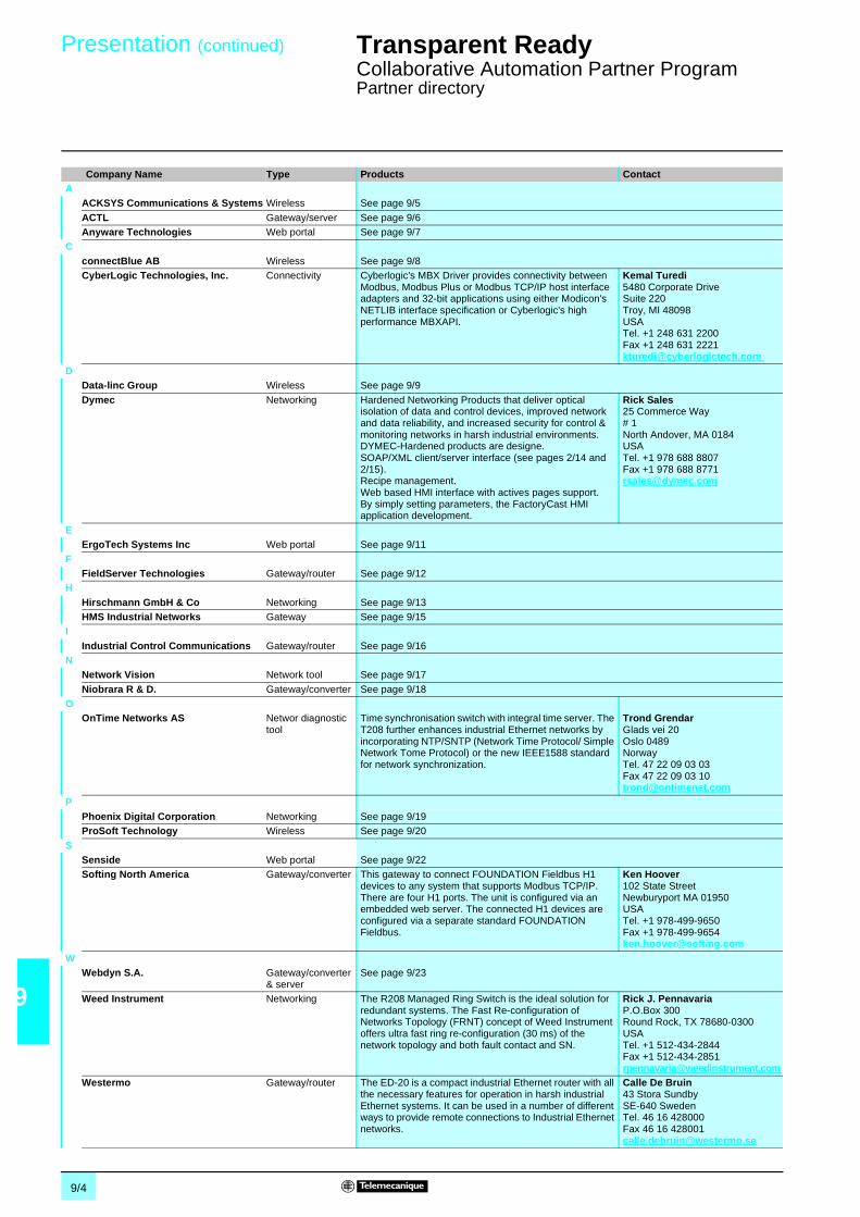
9/4
9
Presentation (continued) Transparent Ready 0
Collaborative Automation Partner ProgramPartner directory
Company Name Type Products ContactA
ACKSYS Communications & Systems Wireless See page 9/5
ACTL Gateway/server See page 9/6Anyware Technologies Web portal See page 9/7
CconnectBlue AB Wireless See page 9/8CyberLogic Technologies, Inc. Connectivity Cyberlogic's MBX Driver provides connectivity between
Modbus, Modbus Plus or Modbus TCP/IP host interfaceadapters and 32-bit applications using either Modicon'sNETLIB interface specification or Cyberlogic's highperformance MBXAPI.
Kemal Turedi5480 Corporate DriveSuite 220Troy, MI 48098USATel. +1 248 631 2200Fax +1 248 631 [email protected]
DData-linc Group Wireless See page 9/9
Dymec Networking Hardened Networking Products that deliver opticalisolation of data and control devices, improved networkand data reliability, and increased security for control &monitoring networks in harsh industrial environments.DYMEC-Hardened products are designe.SOAP/XML client/server interface (see pages 2/14 and2/15).Recipe management.Web based HMI interface with actives pages support.By simply setting parameters, the FactoryCast HMIapplication development.
Rick Sales25 Commerce Way# 1North Andover, MA 0184USATel. +1 978 688 8807Fax +1 978 688 [email protected]
EErgoTech Systems Inc Web portal See page 9/11
FFieldServer Technologies Gateway/router See page 9/12
HHirschmann GmbH & Co Networking See page 9/13HMS Industrial Networks Gateway See page 9/15
IIndustrial Control Communications Gateway/router See page 9/16
NNetwork Vision Network tool See page 9/17
Niobrara R & D. Gateway/converter See page 9/18O
OnTime Networks AS Networ diagnostictool
Time synchronisation switch with integral time server. TheT208 further enhances industrial Ethernet networks byincorporating NTP/SNTP (Network Time Protocol/ SimpleNetwork Tome Protocol) or the new IEEE1588 standardfor network synchronization.
Trond GrendarGlads vei 20Oslo 0489NorwayTel. 47 22 09 03 03Fax 47 22 09 03 [email protected]
PPhoenix Digital Corporation Networking See page 9/19ProSoft Technology Wireless See page 9/20
SSenside Web portal See page 9/22Softing North America Gateway/converter This gateway to connect FOUNDATION Fieldbus H1
devices to any system that supports Modbus TCP/IP.There are four H1 ports. The unit is configured via anembedded web server. The connected H1 devices areconfigured via a separate standard FOUNDATIONFieldbus.
Ken Hoover102 State StreetNewburyport MA 01950USATel. +1 978-499-9650Fax +1 [email protected]
WWebdyn S.A. Gateway/converter
& serverSee page 9/23
Weed Instrument Networking The R208 Managed Ring Switch is the ideal solution forredundant systems. The Fast Re-configuration ofNetworks Topology (FRNT) concept of Weed Instrumentoffers ultra fast ring re-configuration (30 ms) of thenetwork topology and both fault contact and SN.
Rick J. PennavariaP.O.Box 300Round Rock, TX 78680-0300USATel. +1 512-434-2844Fax +1 [email protected]
Westermo Gateway/router The ED-20 is a compact industrial Ethernet router with allthe necessary features for operation in harsh industrialEthernet systems. It can be used in a number of differentways to provide remote connections to Industrial Ethernetnetworks.
Calle De Bruin43 Stora SundbySE-640 SwedenTel. 46 16 428000Fax 46 16 [email protected]

9/5
9
Partner data sheet Transparent Ready 0
Collaborative Automation Partner ProgramACKSYS
ACKSYS is a French company specializing in telecommunication solutions for allindustrial sectors where high performance, reliability and longevity are majorrequirements (industrial control systems, telecommunications, aviation, military,transport and healthcare).
ACKSYS also offers a range of wireless equipment based on the WiFi standard IEEE802.11b. This range comprises an Ethernet/WiFi access point, an Ethernet/WiFibridge and an RS 232, RS 422/RS 485 serial link server on Ethernet WiFi that alsooperates as a gateway between serial Modbus devices and the Modbus TCP/IPnetwork.
These devices can be used to:
b Build a wireless Ethernet network infrastructure (WL-ACCESS devices andWL-BRIDGE devices.b Connect two separate Ethernet networks without using any additional wiring(WL-BRIDGE).b Connect serial link devices to the wireless Ethernet network.b Connect an RTU serial Modbus device to a wireless Modbus TCP/IP Ethernetnetwork (WL-COMETH device in gateway mode).b Create a wireless connection between two serial link devices (WL-COMETHdevice in full duplex radio modem mode).
Unlike conventional, non-WiFi radio modems, which require same brand devices atboth ends of the connection, WL-COMETH offers total interoperability of all devicesconforming to standard IEEE 802.11b within the network, meaning that a singleaccess point can communicate with more than 100 WL-COMETH devices. It is alsopossible to replace a wired full duplex serial link using two WL-COMETH radiodevices.
IP65 weatherproof versions are also available for outdoor applications orapplications in damp or dusty environments.
WL-COMETH is available in versions with 1, 2 and 4 RS 232, RS 422/RS 485 serialchannels. All WL range devices have a built-in a 85/264 V and c 100/370 V or lowvoltage c 9/36 V power supply.
They have universal mounting options (in enclosure, or wall or din rail mounting).Antennas are mounted on RSMA screw connectors allowing the use of high gainantennae for long distance applications.
Installing radio solutions requires specialist expertise. Please contact our partner:
Eric CARIOUACKSYS Communications & SystemsZA du Val Joyeux10 rue des EntrepreneursVillepreux 78450 France
v Tel: +33 (0)1 30 56 46 46v Fax: +33 (0)1 30 56 12 95v E-mail: [email protected] Website: www.acksys.fr
ACKSYS wireless solutionsACKSYS
WL-COMETH WL-COMETH, IP 65
Serial Modbus to Modbus TCP/IP connection
Modbus TCP/IP network interconnection
WL-BRIDGE WL-ACCESS
Modbus TCP/IPnetwork
Modbus serial link(RS 485)
WiFi radio2.4 GHz
Modbus TCP/IPnetwork
WiFi radio2.4 GHz
Modbus TCP/IPnetwork
Wireless solutions for industry (WiFi IEEE 802.11b)
Contact

9/6
9
Partner data sheet Transparent Ready 0
Collaborative Automation Partner ProgramACTL
eWON (eYES Watching Over the Net) is a family of products, ranging from anintelligent Ethernet gateway to a complete remote management solution for PLCs,devices and standalone equipment, with many embedded features, advancedservices and tools.
Fully compatible with the whole range of Schneider PLCs, eWON is the idealconnectivity companion for your applications.
All eWON models are DIN rail mounted and are powered c 12-24 V.They are equipped with a 10/100 Mbps Ethernet port and a RS 232/RS 485 serialport.
b Additionnal features:b Full TCP/IP and PPP RFCs complianceb Embedded web server, http, SMTP, DNSb FTP client & server, SNMP (MIB II & Data)b NTP (Network Time Protocol)b Support for scripts programming (in Basic)b …
Using internal memory tags, eWON publishes, in Modbus TCP/IP and/or in SNMP,data collected through numerous serial protocols, with advanced alarm capabilities.As the RS 232/RS 485 serial port can be accessed directly with scripts in BASIC,eWON decodes proprietary ASCII command sets and protocols of various devices(scalers, tracers, x-meters and more…) making them available to higher endsystems such as ERP, MES, SCADA, Historian, etc…
Either point-to-point or through Internet, thanks to their optional embedded PSTN orGSM/GPRS modem, these eWON models offer efficient RAS service, enablingtransparent operation from PL7 Pro, Concept or Unity, directly to the PLCprogramming port. Using advanced alarm management features, eWON will warnyou of critical situations by mail, SMS or SNMP traps.With its data logging and reporting features, eWON 4001 will even send, at regularintervals or on alarms, by mail or by FTP, a complete production report or a graphwith the latest trends.
Cutting short on delays and development costs, viewON enables everyone to createone's own HMI and production synoptics, on web pages, within minutes and withoutwriting a single line of code. Thanks ot its intuitive menus, animations and objectlibraries, viewON makes design of such complex pages easy and straightforward.
More information: www.ewon.bizWorldwide distributors list: www.ewon.biz/CtDistrib.htm
International Technical Support: [email protected] Sales Information: [email protected]
ACT’L sa10A, avenue de l’artisanatB-1420 Braine L’AlleudBelgium
v Tel: +32 2 387 27 82v Fax: +32 2 384 47 16
eWON : Ethernet Gateway, Remote Access and eSCADAPresentation
Uni-Telway, Modbus RTU, Modbus TCP/IP, XIP
Ethernet and/orRS 232/RS 485
Datalogging
Web Server
Alarms by SMS, E-mail
InternetPSTN
GSM/GPRS
eWON500: Modbus Programmable Gateway
eWON2001 & eWON4001 : PLC Remote Service & Management
viewON : Design your own SCADA-like WEB pages, nice and easy !
Contact

9/7
9
Partner data sheet Transparent Ready 0
Collaborative Automation Partner ProgramAnyware Technologies
Anyware Technologies designs thin client software solutions, which aim at optimizingbusiness performance. Recognized as an expert in the XML and Java world, shebrings innovation up to meet customers needs and expectations.
Our current solutions are offered in the three business areas :b Information Technology Systemsb Automationb Machine to Machine (M2M)
A simple and efficient portal centralizing all your production system data andenabling a secure access from any media (mobile, PDA, computer…):b A central and reliable control systemAlerting you on any events, tracing them and recording the way they have beenmanagedb A powerful and easy-to-use diagnostic tool based on specialized viewers (PLCprograms, electrical CAD, electrical devices and HMI)b An online technical service manual which is easy to consult and update.
A simple and anywhere access to your animated PLC programsFor a diagnostics even more efficient: thin PLC is the Industrial Operating Portalviewer dedicated to the diagnostics of automation functions.
thin PLC enables you to visualize and animate the automation applications in realtime, with a simple web browser. Its user interface (programs, data, configurationparameters, operator screens) complies with the IEC 61131-3 standard. Equippedwith connectors to your external tools (SCADA, control HMI etc.), it gives you a viewof all your PLC programs in a secure environment.
With industrial products and solutions:b Save time and money (deployment, diagnostics, repair, light training…)b Get secure and multimedia access (computer, PDA, mobile…) to any componentof the industrial fittingsb Capitalize on your technical knowledge with an interactive and upgrading technicalmanual.
M2M Developer Suite: A quick and easy software development environment toconnect and manage your remote assets.
M2M Developer Suite is a powerful Graphical Development Environment enablingMachine To Machine applications to be developed, generated and deployed muchfaster than with any traditional development approach, thus minimizing yourdevelopment costs and maximizing your productivity.
In the challenging world of Machine To Machine solutions, development tools canreally make the difference…
Anyware TechnologiesPrologue IIRue Ampère BP 8721631672 LABEGE CEDEX
v Tel: +33 (0)5 61 00 52 90v Fax: +33 (0)5 61 00 51 46v Website: http://www.anyware-technologies.com
Company Presentation
Active Web server
WiFi GPRS
Industrial network
Enterprise networkPLC
programmingtoolk
OPC GPRSModbus –
ElectricalCAD
SCADA
GPRS
Automation products and solutionsIOP (Industrial Operating Portal)
thin PLC (ex-PLC Animator)
M2M products and solutions
Contact

9/8
9
Partner data sheet Transparent Ready 0
Collaborative Automation Partner ProgramconnectBlue
The Bluetooth Serial Port Adapter enables replacement of serial cables withBluetooth wireless technology. Bluetooth is robust, proven and well suited forindustrial applications and is license free to use.
The Serial Port Adapter connected to the RS 232/RS 422/RS 485 port of theindustrial device acts like a wireless connection point to the device. A PC, laptop,PDA or any other serial device may connect wirelessly to the industrial device forranges up to > 100 m. It supports both point-to-point and point-to-multipointconfigurations.
The Serial Port Adapter is configured using a PC Configuration Wizard or by use ofAT commands. The Serial Port Adapter is available in wall/DIN-rail mounted IP 22 orwall mounted IP 65.
1 Operators, programmers etc. are provided wireless access to an industrial devicefor configuration, programming, diagnostics using a standard computer, laptop orPDA.
2 The Serial Port Adapter supports Wireless Multidrop. It is used to replace anRS 422/RS 485 multidrop network (running e.g. Modbus protocol) with Bluetooth.
Installing radio solutions requires specialist expertise. Please contact our partner:
connectBlue AB,INorra Vallgatan 64, Malmö, SE-21122, Sweden
v Tel: +46 (0)40 6307100v Fax: +46 (0)40-237137v E-mail: [email protected] Website: www.connectblue.se
Presentation connectBlue Wireless offerBluetooth Serial Port Adapter (RS 232, RS 422 or RS 485)
IP 22 version IP 65 version
Use Cases - Serial Port Adapter (RS 232, RS 422 or RS 485)
Contact

9/9
9
Partner data sheet Transparent Ready 0
Collaborative Automation Partner ProgramDATA-LINC Group
Founded in 1988, Data-Linc Group has provided exceptionally reliable solutions forindustrial automation systems including expert technical support andcommunications consultation. Data-Linc Group designs and manufactures highperformance, superior quality modems that have been successfully implemented inall major industries including water/wastewater, oil and gas, automotive, consumergoods manufacturing/packaging, steel mills, mines, paper mills, utilities andtransportation systems. Its products are available worldwide having recentlyexpanded its market with a line of wireless modems for the European Unioncountries. Contact Data-Linc for information about their broad product line and theirability to interface seamlessly with Schneider equipment as well as a variety ofmanufacturers’ PLCs and equipment in hybrid and legacy networks.
b License-free and wireless operates in the ISM (Industrial/Scientific/Medical)900 MHz and 2.4 GHz bandsb Compact, flexible design with universal mounting, back panel or on optional DINrail clipb Rated range communication extended by Repeaters and/or high gain antennasb Employs Smart Spectrum™ frequency hopping technology for exceptional dataintegrity and reliability-including high interference environmentsb Wirelessly connects Ethernet PLCs and workstationsb Factory or field configured for your application ensuring trouble-free installationb User configurable for Master, Remote, Repeater or Repeater/Remote modeb Front panel LEDs: Power, RF Link, RF In, RF Out, LAN In, LAN Out, LAN Link,LAN Collision, Overrun Errorb Superior noise immunity, higher power output and better receiver sensitivitycompared to other 2.4 GHz wireless systemsb SRM6310E-EU CE Mark and ETSI compliant for installation in EU countries
Data-Linc Group's SRM6p10E Ethernet Radio Modems offer superior reliability,versatility and performance. The SRM6p10E modems are factory preconfigured foreasy, trouble-free installation. Stated ranges for each of the modems may beextended with higher gain or directional antennas and multiples of this distance withrepeaters.It offers an unsurpassed rated range of:b SRM6210E, 900 MHz ISM band: up to 40 km (25 miles) and an installed range ofup to 56 km (35 miles) in optimal conditions with line-of-sight,b SRM6310E, 2.4 GHz ISM Band: up to 16km (10 miles) with line-of-sight,b SRM6310E-EU, 2.4 GHz ISM Band for European Union Countries (1): up to 8 km(5 miles) with unobstructed line-of-site, and an omni directional antenna.
(1) SRM6310E-EU is designed to meet e European Mark and ETSI RF regulations, It combinesadvanced frequency hopping technology and a highly sensitive RF receiver to maximizetransmission range and industrial performance.
Featuresb Simplifies monitoring and control of large, complex networksb Offers OPC server capabilityb Graphically displays view of entire wireless networkb Provides programmable warning/alarms with loggingb Displays both ends of all RF linksb Supports multiple radio networksb Timestamps last communicationb Delivers historical graphing of key statistics and valuesb Allows re-configuration of each network modem (RF link must first be present)
LincView OPC (OLE for Process Control), Data-Linc's enhanceddiagnostics/management software, allows the monitoring and control of RF networksutilizing the SRM Family of wireless modems. LincView OPC provides the ability totroubleshoot and analyze the performance of RF links in large SCADA networks thussimplifying management of the network and the application together on one screen.
License-free Wireless Solutions from Data-Linc GroupDATA-LINC Group
LincView OPC Enhanced Diagnostics Utility software
SRM6310E-EU, SRM6310E, SRM6210ELong Range Ethernet Radio Modems
Frequency Hopping Spread Spectrum SolutionsFeatures
SRM6p10E License-free Wireless Ethernet Modems
LincView™ OPC Enhanced Diagnostics Utility Software for SRM NetworkManagement

9/10
9
Partner data sheet (continued) Transparent Ready 0
Collaborative Automation Partner ProgramDATA-LINC Group
Featuresb Provides fast, high-speed wireless Ethernet connectivity using the2.412-2.462 GHz license-free spread spectrum bandb High output power and excellent receiver sensitivity for outstanding in-plant RFcoverage and outdoor rangeb Rated range of 8 km (5 miles) with unobstructed line-of-sight (multiples of thisrange using Repeaters)b Coexists with Data-Linc’s Smart Spectrum SRM6210E frequency hoppingtechnology for hybrid 900 MHz and 2.4 GHz RF SCADA systemsb Wireless connections to PLCs, HMIs, Ethernet I/O systems and portablecomputersb Compatible with WiFi and IEEE 802.11b compliant devicesb Functions as a wireless access point, a station adaptor and a bridge with repeatingfunctionb Supports point-to-point, point-to-multipoint and peer-to-peer topologiesb Compact, flexible design with universal mounting including an optional DIN rail clipb Web page (HTML) configuration and diagnosticsb Built-in data encryption and authentication for added securityb Factory or field configured for your application ensuring trouble-free installationb AC or DC powered
FastLinc™ Industrial Ethernet Wireless Modems provide a high-speed, securewireless solution using 2.4 GHz direct sequence technology with connectivity up to11 Mbps (over the air data rate) at distances up to 8 km (5 miles) -multiples of thiswith distance with repeaters. FastLinc modems function as a wireless 802.11baccess point, wireless bridge or remote repeater and supports point-to-point,point-to-multipoint and peer-to-peer topologies for IEEE 802.11b, WiFi compliantcommunications. Both Ethernet stand-alone and PCMCIA models are available.
Featuresb Provides high-speed wireless Ethernet connectivity using the 2.412-2.462 GHzlicense-free spread spectrum bandb High output power (200 mW) and excellent receive sensitivity for exceptionalrange capabilityb PCMCIA card fits within most laptop computersb Compatible with WiFi and IEEE802.11b compliant devicesb Built-in data encryption and authentication for added securityb Includes site survey software
FastLinc™ Industrial Ethernet Wireless Modems are a high-speed, secure wirelesssolution. The FLC800C Industrial Wireless PCMCIA Card provides much higheroutput power than commercially available IEEE 802.11b cards. This greatlyincreases the range in challenging RF environments such as industrial plants. TheFLC800C is ideal for portable computers used to access plant networks for HMI,SCADA, maintenance and PLC programming applications. When used inconjunction with the FLC810E modem, a robust wireless industrial network is createdfor outstanding coverage and high-speed performance. The FLC800C includes asoftware utility for simple configuration and reports RF performance information. Thesoftware provides an easy way to use a portable computer for RF site surveys. Alsoavailable in stand-alone Ethernet (FLC810E) models.
Installing radio solutions requires specialist expertise. Please contact our partner:
DATA-LINC Group3535 Factoria Blvd. SE Bellevue, WA 98006 USAv Tel: +1 425 882 2206v Fax: +1 425 867 0865v E-mail: [email protected] Website: www.data-linc.com
Direct access to the DATA-LINC partnership with Schneider Electric, includingapplications examples: www.data-linc.com/schneider/
High Speed, Direct Sequence Spread Spectrum, WiFiCompliant SolutionsFastLinc™ FLC810E License-free 802.11b High Speed Ethernet Radio Modem
FastLinc FLC800C High Speed Wireless Ethernet802.11b WiFi and IEEE compliant PCMCIA card
FastLinc FLC800C License-free 802.11b High Speed Ethernet PCMCIA Card
Contact
FastLinc FLC810E High Speed Wireless Ethernet802.11b WiFi and IEEE compliant modem

9/11
9
Partner data sheet Transparent Ready 0
Collaborative Automation Partner ProgramErgo Tech Systems Inc.
ErgoTech was founded in 1994 as a developer of factory automation software. Weshipped our first Java-based product in 1998, a suite of JavaBeans™ (VirtualInstrumentation Beans).
We are committed to providing quality products for factory automation based on openmulti-platform technology. Our tool-chain and components are Java-based and relyon XML technology and other open standards.
We have several OEM relationships and welcome more. We also have distributorsworldwide (Scandinavia, United Kingdom, U.S.A., and Benelux) and are seekingother qualified organizations to add value to or resell our products with addedservice.
ErgoVU is a complete solution for data collection and visualization. It is ideal forWeb-enabled HMI, SCADA, and operator panels. ErgoVU goes beyond simple HMIinformation displays -- it is also an application that collects data, alarms, andhistorical data 24/7. ErgoTech's easy-to-use screen builder (VIBLaces) lets youdesign SCADA-like screens from any computer workstation. Once complete, thescreens are uploaded to the ErgoVU system and the “front-end” graphics can beviewed on the display of this system, or over the Web with any Web browser, whilethe “back-end” logic runs 24/7 on the ErgoVU system to deliver information to theseviews.
ErgoVU can be purchased as a turn-key software solution. It is installable onWindows NT/2000 or any other platform with a JVM, including Linux and other UNIXoperating systems. On Windows platforms, ErgoVU can run concurrently with ourOPC Gateway to provide information from third-party OPC Servers. ErgoVU is anintegral part of ErgoTech's “Develop and Deploy” software package and is distributedwith VIB and VIBLaces as part of this package.
ErgoVU, is a pure Java application and can run on many platforms of many sizes.We routinely deliver it to run on compact flash in industrial PC platforms usingembedded Linux. This same hardware can support ErgoVU running on a full Linuxinstallation on a hard drive with a database for historical logging capability. ErgoVUis packaged in our “Develop and Deploy” package with the OPC Gateway forWindows systems, either running stand-alone or in conjunction with other third-partySCADA or PC Control applications. We have OEMs licensing ErgoVU to run onJava-enabled operator stations, on some very small units with quarter-VGA LCDscreens. Our Beans are now being converted for use on PDAs, Wireless Devices,Palms, etc. that run a minimal version of Java called “Micro Edition”.
ErgoTech Systems, Inc.190 Central Park SquareLos Alamos, NM 87544
v Tel: +1 505.662.5156v Fax: +1 775.254.3299v U.S. Sales: +1 888 ERGOTECHv E-mail: [email protected]
Web based applicationsErgo Tech Systems Inc.
ErgoVU
Contact

9/12
9
Partner data sheet Transparent Ready 0
Collaborative Automation Partner ProgramFieldServer Technologies
The FieldServer Technologies gateway provides the link from multiple devices toModbus TCP/IP (and other Modbus protocols including Modbus RTU, ModbusASCII, and Modbus Plus). With over 85 different protocol drivers proven to interfaceto over 350 different devices, FieldServer is the leader in protocol gateways in theprocess control and building automation industries. The FieldServer driver libraryincludes such common protocols as BACnet, LonWorks, Modbus TCP/IP and manyproprietary networks, plus most legacy protocols for devices such as Caterpillar,Data Aire, McQuay, Carrier, and all major Fire Alarm Panels.
The FS-B20 Series is a serial to Ethernet gateway used to bring legacy devicesutilizing a serial protocol to Modbus TCP/IP. This series has a serial port, LonWorksport and Ethenet and has the ability to handle up to 1000 points of information.
http://www.fieldserver.com/products/gateways/FS-B2010.asp
For applications requiring additional points or additional protocols the FS-B30 seriesmeets the needs with 4 serial ports, LonWorks port and 2 Ethernet ports. In addition,Third party network ports are available. The multiple serial ports enable the user tobring in multiple serial devices and FieldServer software can combine thatinformation into a common Modbus TCP/IP connection.
http://www.fieldserver.com/products/gateways/FS-B3510.asp
The FS-B40 Series has 10 serial ports, 2 Ethernet ports and a fieldbus port for suchprotocols as LonWorks, and others. The FS-B40 is ideal for plant wide applicationsrequiring input from multiple serial and Ethernet devices to link to Modbus TCP/IP.
http://www.fieldserver.com/products/gateways/FS-B4010.asp
FieldServer Technologies1991 Tarob CourtMilpitas, California 95035 USA
v Tel: 408-262-2299v Toll Free: 888-509-1970v Fax: 408-262-9042Sales Support:v Tel: 408-262-2299 x125v E-mail: [email protected] On-line: Complete our Sales Information Contact form
FieldServer GatewayFieldServer Technologies
FS-B20 Series
FS-B30 Series
FS-B40 Series
FS-B20 Series
FS-B30 Series
FS-B40 Series
Contact

9/13
9
Partner data sheet Transparent Ready 0
Collaborative Automation Partner ProgramHirschmann Electronics
Hirschmann Electronics is a multi-national manufacturer of the broadest line ofindustrial networking products available today including transceivers, hubs,unmanaged and managed switches, network management software, and fiberinterface products. Hirschmann was one of the early pioneers of Ethernet and nowspecializes exclusively in factory, process, and transportation automationapplications.
Hirschmann Electronics is an innovator of industrial Ethernet products. This includesswitches for Ethernet, Fast Ethernet, and Gigabit Ethernet. With advances inswitching technology, Ethernet has become completely deterministic. Hirschmannmanaged switch capabilities include redundancy options, full duplex, port mirroring,IGMP Snooping for multicast filtering, and VLAN support for increasing networkefficiency and security.
Hirschmann is a strategic Schneider Electric partner in the promotion anddevelopment of Industrial Ethernet.
Fast Ethernet switch with Flexible Gigabit uplink modules, the chassis is a fixedintegrated component store and forward switching mode, Ethernet (10 Mbps), FastEthernet (100 Mbps), Gigabit Ethernet (1000 Mbps).
Characteristics
Ethernet Firewall or Firewall w/VPN. Devices capable of facilitating so-calledbump-on a wire firewall security as well as static routing or VPN Virtual PrivateNetworks in 10/100 half/full duplex.
Characteristics
Wireless Ethernet Access Point or Access Client. Devices in the wireless 802.11brange @ 11 Mbps with 2 10/100 half/full duplex Ethernet ports.
Characteristics
Switches, Wireless AP’s/AC’s and Security AppliancesHirschmann GmbH & Co
LION 24 TP Workgroup Switch
Management SNMP v1, v2, v3, RMON 1,2,3 and 9, Web Interface, Telnet,BootP
Diagnostics LED’s (power, link status, data error)Configuration TELNET, terminal SW, BOOTP, DHCP
Security Radius, TACACS+, SSL, SSH, ACL, 802.1x port security*Other services MDI/MDIx, 8k MAC addresses, Flow control, HOL, Port mirroring,
IGMP w/Querier, Broadcast storm controlsRedundancy Spanning and Rapid Spanning Tree, Link AggregationMax. data rate 8 Gbps, 5.9 million packets per second
Eagle Security System
Management Serial interface (CLI), HTTPS secure web interface or SNMP
Diagnostics LEDs (power, link status, data, error, ACA), HiDiscovery,signaling contact
Configuration Terminal SW, DHCP, Auto configuration adapter ACA,HiDiscovery and remote file and config storage
Other services DHCP server, DHCP client, DynDNS and dial-in access via v.24 portFilters Via IP address, Subnets or ProtocolsOperating Voltage c 24 V
Encryption Methods DES-56, 3DES-128, AES-128, AES-192, AES-256Authentication PSK or pre-shared secret, X.509v3
BAT 11b Wireless AP/AC
Management Bat Discovery Protocol, Web InterfaceDiagnostics LEDs (power, link status, data, error), Bat Discovery
Configuration DHCP, Bat DiscoveryEncryption None, WEP-64, 128, WEP plus, WPAAntenna Connector Dual RSMA antenna connectors for diversity
Operating Voltage c 24 VEncryption Methods Access Point (Infrastructure) Access Client (Ad-Hoc)Authentication 160 m outdoors and 30 m Indoors

9/14
9
Partner data sheet (continued) Transparent Ready 0
Collaborative Automation Partner ProgramHirschmann Electronics
Modular Gigabit switch with optional routing, the basic board is a fixed integratedcomponent store and forward switching mode, Ethernet (10 Mbps), Fast Ethernet(100 Mbps), Gigabit Ethernet (1000 Mbps).
Characteristics
Modular Gigabit switch with optional routing, the basic board is a fixed integratedcomponent store and forward switching mode, Ethernet (10 Mbps), Fast Ethernet(100 Mpbs), Gigabit Ethernet (1000 Mbps).
Characteristics
Hirschmann Automation and Control GmbHStuttgarter Strasse 45-5172654 NeckartenzlingenGermany
v Tel: +49(0)7127/14-0v Fax: +49(0)7127/14-1214v Website: www.hirschmann.com
Switches and routeursMach 3001
Management Serial interface, web interface, SNMPv1, HiVision, automatictopology detection (IEEE 802.1ab)
Diagnostics LEDs: Integrated power supply unit (PSU1), c 24 V connections(PSU2, PSU3), integrated fans (FAN1 to FAN4), integrated basicboard (BOOT/RUN, MASTER/SLAVE, ERROR), 4 simultaneousRMON groups at each port (statistics, history, alarms, events),port mirroring
Configuration TELNET, terminal SW, BOOTP, DHCP, DHCP option 82,auto-configuration adapter (ACA 11), HiDiscovery
Security SNMP security, port security, VLAN’s 802.1QOther services Prioritization (IEEE 802.1D/p), VLAN (802.1Q), multicast
(IGMP snooping/Querier, GMRP), broadcast limiter, SNTP(Simple Network Time Protocol), flow control IEEE 802.3x
Protocols protocols: RFC791(IP), RFC792 (ICMP), RFC793 (TCP/IP),RFC768 (UDP), RFC826 (ARP), RFC950 Internet standardsubnetting procedure with the M-ROUTER module
Max. data rate 8 Gbps, 5.9 million packets per second
Mach 3002/3005
Management Serial interface, web interface, SNMPv1, HiVision, automatictopology detection (IEEE 802.1ab)
Diagnostics LEDs: Integrated power supply unit (PSU1), c 24 V connections(PSU2, PSU3), integrated fans (FAN1 to FAN4), integrated basicboard (BOOT/RUN, MASTER/SLAVE, ERROR), 4 simultaneousRMON groups at each port (statistics, history, alarms, events),port mirroring
Configuration TELNET, terminal SW, BOOTP, DHCP, DHCP option 82,auto-configuration adapter (ACA 11), HiDiscovery
Security SNMP security, port security, VLAN’s 802.1QOther services Prioritization (IEEE 802.1D/p), VLAN (802.1Q), multicast
(IGMP snooping/Querier, GMRP), broadcast limiter, SNTP(Simple Network Time Protocol), flow control IEEE 802.3x
Protocols protocols: RFC791(IP), RFC792 (ICMP), RFC793 (TCP/IP),RFC768 (UDP), RFC826 (ARP), RFC950 Internet standardsubnetting procedure with the M-ROUTER module
Max. data rate 8 Gbps, 5.9 million packets per second
Contact

9/15
9
Partner data sheet Transparent Ready 0
Collaborative Automation Partner ProgramHMS Industrial Networks
HMS Industrial Networks is a world leader in industrial networking, IndustrialEthernet and Fieldbus Communication, supplying products to the global world ofautomation. The Anybus range of products from HMS is today the world's most usedthird party product for industrial network connectivity.
Anybus products help OEM’s, integrators and end-users to connect their products toall major industrial networks, such as Ethernet Modbus TCP/IP, Modbus Plus, Fipio,Profibus DP, DeviceNet, EtherNet/IP, Profinet, Modbus RTU, CC-Link, ControlNetand CANopen. Anybus products are available as intelligent embedded modules,external networking gateways as well as PCI interfaces.
Anybus-S and Anybus-MOne single integration project of the embedded interfaces from HMS givescustomers a complete coverage of all major Fieldbus and Industrial Ethernetnetworks. The proven credit-card-sized Anybus-S slave interfaces and Anybus-Mmaster interfaces support 15 different networks, allowing customers to focus on theircore competence, using Anybus technology to connect their products to networks.
Anybus CompactCom – the new generation of embedded interfacesThe module-based range of embedded boards Anybus CompactCom takesembedded communication one step further. There is one separate low-pricedAnybus CompactCom-module for each major industrial network, all of them featuringthe size of half a credit-card.
Anybus CompactCom reflects the needs of modern industrial communication,allowing for tight integration to the host application. The integration procedure is verystraight-forward - the customer only needs to add a simple Compact Flash connectorto the host board, which will only add a minimum of cost to the design. The AnybusCompactCom modules are interfaced through the use of the Anybus CompactComdriver, which is available inside the Anybus CompactCom Starter kit. The starter kitalso contains a series of modules and an adapter, enabling a developmentenvironment connected to a standard PC.
Anybus Communicator connects products with serial interfaces to all major fieldbusand Industrial Ethernet networks. There is one separate version of AnybusCommunicator for each major industrial network, such as Ethernet Modbus TCP/IP,Fipio, Modbus RTU, Modbus Plus, Profibus DP and DeviceNet. On the serial side, itis as default configured as a fully implemented Modbus RTU Master, which isdesigned to communicate with a sub-net with one or several Modbus RTU slavedevices. It can be configured to support also other serial protocols as well as simpleASCII-communication. The PC-based ABC Config Tool allows an easy step-by-stepconfiguration of the communication between devices on the serial subnet and thePLC master on the other side of the Anybus Communicator. The configuration canbe saved to be re-used in future integration projects.
The Anybus-X Gateway family includes over 150 different versions which connectalmost every possible combination of two industrial networks allowing for instant andpowerful integration. Anybus-X supports integration to and from 15 different fieldbusnetworks, such as Ethernet Modbus TCP/IP, Modbus Plus, Profibus DP, DeviceNet,CANopen and CC-Link. Equipped with aluminum housing, the Anybus-X is designedto withstand harsh industrial environments, helping system integrators to easilyinterconnect between different networks, ensuring a transparent information flowthroughout the entire plant.
The network architecture to the left shows Anybus Communicator and Anybus-Xconnected to the same PLC on Ethernet TCP/IP. In this scenario, AnybusCommunicator integrates Modbus RTU slave devices and Anybus-X links theEthernet Modbus TCP/IP network to any other industrial network.
HMS Industrial NetworksCompany and product overview
Ethernet ModbusTCP/IP
ASCII
Modbus PlusFipioProfibus DPDeviceNet…
RS 232/422/485Modbus RTU
Embedded Anybus CompactComfor Ethernet/Modbus TCP/IP
Anybus Communicator - serial to network gateway
Anybus-X - network to network gateway
Gateway integration to Ethernet Modbus TCP/IP
Embedded Anybus technology for OEM manufacturers
Powerful network integration through Anybus Gateways
Contact
HMS Industrial NetworksPilefeltsgatan 93-95,S-30250 Halmstad, Sweden,
v Tel: +46 35 17 29 00v Fax: +46 35 17 29 09v E-mail: [email protected] Website: www.Anybus.com

9/16
9
Partner data sheet Transparent Ready 0
Collaborative Automation Partner ProgramIndustrial Control Communications
The ETH-200 Ethernet Multiprotocol Network Gateway allows information to betransferred seamlessly between many different fieldbus networks with minimalconfiguration requirements. The ETH-200 provides:b A 10BASE-T/100BASE-TX Ethernet port,b Two RS 485 ports,b One RS 232 port,b Three common serial ports for direct connectivity to Toshiba 7-series, 9-series,11-series or VF-nC1 Adjustable Speed Drives (ASDs).These various communication ports operate independently, and are configurablealong with the unit's internal point database via a standard web browser.
The ETH-200 currently provides support for the following protocols, with others underdevelopment:b Modbus TCP/IP (slave)b Ethernet/IP (server)b Modbus RTU (RS 485 master & slave)b Modbus RTU (RS 232 master & slave)b Johnson Controls, Inc. Metasys N2 (RS 485 slave)b Sullair Supervisor network (RS 485 master)b Toshiba ASD (common serial master)b Toshiba 3-series ASD (RS 232 master)b Mitsubishi ASD (RS 485 master).
Don’t see a protocol that you need ?Give us a call: we’re always willing to investigate the implemenation of additionalopen or customer-specific drivers.
The ETH-200 is a member of the ICC Network Gateway Series product family.Members of this family are designed to provide a uniform interface, configuration andapplication experience. This commonality reduces the user's learning curve,reducing commissioning time while simplifying support. The ETH-200 providessimultaneous support for many different communication protocols, allowing complexinterchanges of data between otherwise incompatible networks.
The heart of the Network Gateway Series concept is an element called the “pointdatabase”. The point database is entirely user-configurable, and provides themapping information that allows requests from the various supported networks to beinterpreted and stored in a common format. This allows data to be routed from anysupported network to any other supported network.
Additionally, the point database provides the added benefit of “data mirroring”,whereby current copies of point values (populated by a “source port” designation) aremaintained locally within the gateway itself. This greatly reduces therequest-to-response latency times on the various networks, as requests (read orwrite) can be entirely serviced locally, thereby eliminating the time required toexecute a secondary transaction on a different network.
When properly configured, the gateway will become essentially “transparent” on thenetworks, and the various network devices can engage in a seamless dialog witheach other.
Industrial Control Communications, Inc.2204 Timberloch Place, Ste. 250The Woodlands,TX 77380 USA
v Tel: +1 281 292 0555v Fax: +1 281 292 0564v E-mail: [email protected] Website: www.iccdesigns.com
Industrial Ethernet GatewaysETH-200 Multiprotocol Network Gateway
Contact

9/17
9
Partner data sheet Transparent Ready 0
Collaborative Automation Partner ProgramNetwork Vision
Network Vision Inc. was founded by a group of professionals who were eager to bringtheir ideas about industrial Ethernet to the automation industry - an industry thatrequires constant innovation and process improvement.
Unencumbered by corporate bureaucracies, and possessing extensive technical andmarketing experience allows the company to be agile and responsive to the evolvingmarkets.
Network Vision's goal from the start has been to design software for the plant floorthat is easy to use and can effectively handle factory floor applications. With the kindof global growth that is expected for industrial Ethernet applications, Network Visionis a strong proponent of support tools require for successful deployment andcontinual operation. Network Vision's flagship software, called IntraVUET, providesa powerful, yet easy to use, network and device visualization tool to the automationindustry. The software is also adaptable to multiple applications in which the networkavailability is important.
IntraVUE is a software package that provides true automatic network mapping andreal-time monitoring function. Utilizing Ping, SNMP information and advancedalgorithms, IntraVUE™ automatically draws an accurate connection diagram of thenetwork. The software is installed on a computer that resides on the network and isrunning continuously. IntraVUE displays are viewed through a browser interface,thus allowing several people to view the real-time availability of the network on theirown computer, or any computer accessing the webserver of the IntraVUE computer.Using a patented Hyperbolic representation, the entire network is displayed on asingle screen.
IntraVUE is often applied in a network that may be a distance from the individualsresponsible for supporting it. It may be in different facilities, remote pumping stations,electrical substations, or plants that are in other countries. The use of a browser toaccess IntraVUE provides you with capabilities as if you were local to the network.
Network Vision, Inc.44 Merrimac StreetNewburyport, MA 01950
v Tel: +1 978 499 7800v Toll Free (US): 877 499 8100v Fax: +1 978 4997860v E-mail: [email protected]
Network Vision Inc.
IntraVUE
Contact

9/18
9
Partner data sheet Transparent Ready 0
Collaborative Automation Partner ProgramNiobrara Research & Development Corporation
Niobrara is a U.S. company specializing in industrial data communication productsfor many of Schneider Electric’s product lines. Our products are sold exclusivelythrough the Schneider Electric channels worldwide.
Niobrara’s QUCM-OE is a bridge, router, protocol converter and data concentrator inSchneider’s Quantum form factor. It has a 10BASE-T Ethernet port and twoswitch-selectable RS 232/RS 485 ports. The QUCM supports a long list of protocolsand can appear to the Quantum processor as either I/O or an option module.For serial and Ethernet protocols not listed below, the QUCM is also auser-programmed module. The user can develop his own programs or, for a veryreasonable price, Niobrara can write QUCM code to incorporate your devices into theTransparent Ready architecture.
Niobrara makes several Ethernet modules for the Compact line. Each has a10BASE-T Ethernet port. All are Schneider Electric Collaborative AutomationPartner Program (CAPP) products and all are e marked:b The CNOE-211 is an Ethernet option module for the newer Compact processors.It has capabilities very similar to the original Quantum NOE-211.b The CUCM-OE is a bridge, router, protocol converter and data concentrator inSchneider’s Compact form factor. It has a 10BASE-T Ethernet port and twoswitch-selectable RS 232/RS 485 ports. The CUCM supports a long list of protocolsand can appear to the Compact processor as either I/O or an option module.
Nota : For serial and Ethernet protocols not listed below, the CUCM is also a user-programmablemodule. The user can develop his own programs or, for a very reasonable price, Niobrara canwrite CUCM code to incorporate your devices into the Transparent Ready architecture.
Niobrara was the first to make PowerLogic devices Transparent Ready. Niobrara’spresent offering, the PEN-T, has a 10BASE-T Ethernet port and can support up to32 PowerLogic meters and Modbus devices on its 4-wire RS 485 port. It will attachto the back of a 2000-series circuit monitor or can be used stand-alone(P/N PEN-T-SA).
Niobrara manufactures an array of communication products for Square D’s SY/MAXPLC line. Two of these products are Transparent Ready:b The MEB-RT allows Transparent Ready access to Modbus Plus devices andSY/MAX Ethernet devices as well as a host of serial devices. It has aredundant-cable Modbus Plus port, a 10BASE-T Ethernet port and two RS 485 serialports.b The EPE5-T is an Ethernet port expander in the SY/MAX form factor. It allowsSY/MAX, PowerLogic and other devices to be used in the Transparent Readyarchitecture. It can also bridge between Modbus TCP/IP and SY/MAX Ethernet.
Gateways, bridges and protocol convertersNiobrara R&D Corporation
QUCM-OE
CNOE-211 CUCM-OE
PEN-T
MEB-RT EPE5-T
Quantum-compatible Transparent Ready products
Compact-compatible Transparent Ready products
PowerLogic compatible Transparent Ready products
SY/MAX compatible Transparent Ready products
Niobrara Supported Protocols
- Modbus RTU Master- Modbus RTU Slave- Modbus ASCII Master- Modbus ASCII Slave- Jbus Master- Jbus Slave- SY/MAX point-to-point- SY/MAX net-to-net- Dual Slave Modbus &SY/MAX- Dual Master Modbus RTU &RNIM- Modbus Plus
- Modbus TCP/IP- HTTP- FTP- SNMP- SY/MAX Ethernet- INTERBUS- LonWorks- Seriplex- Metasys- Johnson N2- Landis P1- INCOM- ASCII
- DNP 3.0- RNIM- PNIM- Plogic- IDEC- SEAbus- SEAbus +- Gateway- Multidrop- Peripheral- Transparent- Share- DF1
Contact
Kenton FosterNiobrara R&D CorporationP.O. Box 3418Joplin, MO 64803-3418
v Tel: +1 417 624 8918v Fax: +1 417 624 8920v E-mail: [email protected] Website: www.niobrara.com

9/19
9
Partner data sheet Transparent Ready 0
Collaborative Automation Partner ProgramPhoenix Digital
Phoenix Digital fiber optic communication modules and cable provide completePhysical Layer Network Solutions for both Open Standard Networks and theCommunication/Control Networks of every major Control System Supplier in theWorld.
Phoenix Digital offers Fiber Optic Modules and Cable for Programmable Controllers(PLCs) and Distributed Control Systems (DCS). Our products provide fiber opticcommunication solution, including fault tolerant, self-healing, very long distances,and network-topology independed (daisy-chain, star, point-to-point) critical features.
Fiber optic modules provide optical communication media, transparent to thecommunication protocol and configurable for distribution by the user in: ring, bus,star, tree, Helix or point-to-point network installations.
It also provides a continuous error checking for jitter, pulsewidth distortion, carriersymmetry, and optical signal strength. All of this, together with comprehensiveself-test diagnostics, optimizes the overall integrity of Ethernet, Modbus, ModbusPlus, and Modicon Quantum Remote I/O (RIO) communication networks at-large,providing high relaiable data communications for control and automation networking.
Characteristicsb 10/100 Mbps Ethernet, Modbus Plus, Remote I/O, Modbus, Modbus TCP/IP,RS 232/RS 485b Fault Tolerant, self-healing communications with 1 ms recovery timeb Phoenix Digital’s proprietary Queuing System (PQS) to improve the networkperformance insuring even faster thruput for user identified network nodesb Unlimited modules for complex multi-drop networksb Real-time diagnosticsb Auto-negotiation, auto-crossoverb 850/1300 nm multimode, 1300/1550 nm monomode FX, ST, SC, MTRJ, and LCfiber optic connectivity, and up to 90 km inter-modular distanceb Available with single or dual power supply system for a 120/240 V, c 125 V, andc 24 Vb UL Class I, Division 2 Rating
Phoenix Digital Corporation7650 E. Evans Rd.Building AScottsdale, AZ 85260
v Tel: +1 480 483-7393v Fax: +1 480 483-7391v E-mail: [email protected]
NetworkingPhoenix Digital Corporation
DIN-Rail panelmount standalone modules
Contact

9/20
9
Partner data sheet Transparent Ready 0
Collaborative Automation Partner ProgramProSoft Technology
ProSoft Technology, Inc. was formally incorporated in 1990. By 1993 ProSoft haddeveloped an extensive protocol library which helped them evolve from a singleproduct company to a multiple product provider. Since then, ProSoft has become amajor supplier of communication products for the industrial automation industry.ProSoft Technology has an extremely active product development program andcustomer recognition of their product quality. ProSoft serves the automationindustry’s communications and specialized applications needs with high qualityproducts, application expertise, and technical support. Sales, applicationengineering, and support services are provided internationally by over 450 exclusivedistributors served by their Regional Area Offices located in:b North America: Seven regional area managers provide coverage for ourdistributors across the continentb Latin America: Two full service offices; one servicing Brazil exclusively, and theother provides coverage to South Americab Europe: One full service office based in France serves Europe, Middle-East andAfricab Asia Pacific: Offices in India and Malaysia servicing Asia, India, Australia andNew ZealandS
b Secure wireless communications with data encryption, proprietary radio protocol,and 2.4 GHz FHSS physical layerb Dual antennas for maximum performance and networking flexibilityb Up to 25 km (16 miles) range with high-gain antennas (longer with repeaters)b Remote diagnosticsb User-programmable over the air (after initial configuration) with easy-to-useWindows-based softwareb Up to 1000 addressed devices with 2000 radios and 78 repeaters per networkb 32 user-selectable data channels for multiple network operationb Uses a proprietary RF protocol and 158 unique hopping patterns to preventunwarranted interception of RadioLinx data transmissionb Class 1 Div 2 rated for hazardous locationsb Modems available include: Serial (RLX-FHS), Ethernet (RLX-FHE) and Ethernetwith Serial Server (RLX-FHES)
The RadioLInx Industrial Hotspot (RLX-IH) is an ultra-fast wireless solution for themost demanding industrial applications. While providing the benefits of industrialwireless Ethernet connectivity for fixed or mobile devices with10BASE-T/100BASE-TX Ethernet connections, the RLX-IH acts as a repeater andan industrial hotspot for other wireless client devices:b Four times more powerful than high-speed commercial grade radios, RLX-IHallows better coverage of the factory floor with fewer radios and outdoor links of32 km (20 miles) (subject to country regulations)b Single unit repeater functionality; no more stringing Ethernet cable betweenwireless access pointsb Attach an Ethernet device directly to the RLX-IHb Powerful transmitter with amplifier option for long range outdoors and superiorcoverage with fewer radios indoorsb Security you can trust with strong TKIP encryption, 802.1X and MAC IDauthentication
The ProTalk Q communication modules are Quantum/Unity backplane compatibleallowing Quantum processors to easily interface with alternate networks:b Single Slot: Quantum backplane compatibleb Recognized as an Options module and has access to PLC memory for datatransferb Simple text configuration file is used to setup and define the module’s operation
ProTalk Q applications include:
Wireless Communication2.4 GHz Frequency Hopping Spread Spectrum
RLX-FHp
RLX-IH
RadioLinx Industrial Hotspot (IEEE 802.11b)
ProTalk Q in-rack interface modulesProtocol Interfaces for Modicon Quantum/Unity
- ‘C’ programmable- DF1- DNP 3.0- DNP 3.0 over Ethernet- HART Multi-drop- Flow computer- Ethernet/IP
- IEC 60870-5-101 Slave- IEC 60870-5-103 Master- IEC 60870-5-104 Server- Profibus DP

9/21
9
Partner data sheet (continued) Transparent Ready 0
Collaborative Automation Partner ProgramProSoft Technology
ProLinx Communication Gateways provide protocol connectivity between twonetworks with over 150 connectivity options. These stand-alone, DIN-rail mounted,industrial gateways are available in two form factors:b The original ProLinxb The new ProLinx Plus extruded aluminum enclosure
ProLinx Plus offers the same connectivity options as in the original gateways andinclude optional H or G mount capabilities.
Protocol combinations include:
For Quantum/Unity interfaces, wireless communication or stand-alone gatewaysplease contact our partner:ProSoft Technology, Inc.v Asia Pacific: +603 7724 2080v Europe: +33(0)5 34 36 87 20v Latin America: +1 281 298 9109v North America: +1 661 716 5100v E-mail: [email protected] Website: www.prosoft-technology.com
ProLinx Communication GatewaysStand-alone, DIN-rail mounted gateways
Original ProLinx (4000 Series)
ProLinx Plus (5000 Series)
- Modbus TCP/IP to DF1- Modbus TCP/IP to Modbus- Modbus TCP/IP to DNP Slave- Modbus TCP/IP to DNP Master- Modbus TCP/IP to IEC 60870-5-101 Slave- Modbus TCP/IP to IEC 60870-5-103 Master- Modbus TCP/IP to IEC 60870-5-104 Server- Modbus TCP/IP to ASCII- Modbus TCP/IP to DH-485
- Modbus TCP/IP to Modbus Plus- Modbus TCP/IP to PROFIBUS DP Slave- Modbus TCP/IP to PROFIBUS DP Master- Modbus TCP/IP to Remote I/O- Modbus TCP/IP to EtherNet/IP- Modbus TCP/IP to DNP over Ethernet- Modbus TCP/IP to HART Multi-drop- Modbus TCP/IP to Honeywell DE
Contact

9/22
9
Partner data sheet Transparent Ready 0
Collaborative Automation Partner ProgramSenside
Senside offers solutions that are innovative and complete for remote access andmanagement of machines’ installed base, to machines builders and systemintegrators.Senside solution enables optimisation of after-sales service for machine builders orintegrators and the development of value added services for machines and systemsusers.Senside is a subsidiary of Schneider Electric (80%), in partnership withFrance Telecom: this alliance brings together, within Senside, a unique expertise inindustrial automation and telecommunications.
A turnkey solution:b Simple to set up and easy to use, reliable and secured.b Available worldwide through the Equant (France Telecom) private IP network(140 countries).A multi-protocol solution:b Available on the whole Telemecanique PLC (Twido, Micro, Premium, Momentum,Quantum) and drives (Altivar) product families.b Compatible as well with MPI, DF-1, Ethernet protocols.A complete solution, provided on the basis of a yearly subscription including:b e-Collecto (server connected to the machine control system, shipped with cablingand installation guide).b Machines access portal, operated by Senside and accessible via Internet.b Private IP network ensuring a reliable and secure connection to the machines (viaa standard local telephone line).b Training, maintenance and support.
Remote access to machines or Installations:b Remote viewing and/or modification of machine control device programmes.b Remote control of SCADA PCs.b Remote access to local Web servers.Web Portal:b Global view of the machine installed base and its status.b Automatic set up of the remote connection to a given machine.Access rights management:b Users authentication via Personal Login/password.b Users profiles management: machine perimeter (geographic criteria, machine username, machine model…) and applications features (consultation, programmation…).Remote access security:b No access to the Machine telephone line from outside Senside network.b Physical key provided to the machine local operator for locking/unlocking accessto the control programmable devices.Monitoring of status and variables:b Definition by the customer of the status or variables to be monitored.b Alarm notification sent by SMS, FAX or E-mail in case of drift (modification on theportal of alarm threshold and notification list).Connection continuity checking:b To the Senside e-Collector.b To the machine control devices (PLC, PC).Options:b Data logging and history storing.b Online documentation sharing.b Brand labelling (portal personalisation with customer logo and brand).
b A yearly subscription, no initial investment.b A turnkey platform “ready to use”.b A better control over installation and process tuning.b A common diagnostic tool, to be shared between machine builder/systemintegrator and user.b A continuous feedback on the performances of the installed base.
Cedric de la Chapelle, Head of MarketingTel: + 33 1 41 29 82 25E-mail: [email protected]: www.senside.com
Senside Presentation
Senside Pack, the principles
The installed base Global view
The Alarm view
Senside pack, detailed features
Benefits
Contact

9/23
9
Partner data sheet Transparent Ready 0
Collaborative Automation Partner ProgramWebdyn
Webdyn, a French company created in 1997, is aEuropean leader in Internet gateways. It develops andmanufactures hardware and software solutions,dedicated to the emerging embedded Internet marketfor industrial, audiovisual and residential equipments.Webdyn solutions are used in a wide range of industrialapplications in Building Automation, Energy,Environment, Automation and Telecom.
Webdyngate Easy allows you to transform a serialindustrial network into a TCP/IP network. Thanks to theWGE–M all the functions defined within the Modbusprotocol are included: serial master/slave,TCP/IP client/server. To secure the network and yourindustrial process, a redundancy option can be addedto the gateway.
By using a WGE-S version together with serial/IP GatePC software, industrial equipment can be monitoredthrough TCP/IP link. This gateway is particularly suitedto applications dedicated to PLC supervision (ie:PL7 Pro, TwidoSoft, Crouzet Logic Software andmore).
The Webdyngate Power allows you to develop andpersonalize remote management and maintenanceapplications using standard tools (Web Browser,E-mail server) and protocols (TCP/IP, HTTP, SMTP).
This gateway offers different levels of personalization.A complete portal can be developed and stored in thegateway flash disk. In order to meet specific customerrequirements, dedicated Plug-in DLL in “C” can beadded to the gateway. Thanks to the embedded JavaVirtual Machine, “Java” applications can be executeddirectly on the gateway.
The WGP version is compatible with the Modbus,Profibus and Uni-Te protocols. The customer canconfigure and manage industrial equipments withstandard HTML pages using any Web Browser.
A V90 or GSM/GPRS modem may be embedded in thegateway.
Jacques Tabor, Channel Sales ManagerWebdyn S.A.
v Tel: +33 (0)1 39 04 29 62v Fax: +33 (0)1 39 04 29 41v E-Mail: [email protected] Website: www.webdyn.com
Webdyn Presentation
Webdyngate Easy
Webdyngate Power
Contact
RS 485
Internet Explorer
Internet Explorer
PSTN, ISDN, ADSL …
Internet ISP
LAN
WGE ModbusTCP Server
Serial Modbus Master
WGE ModbusTCP Client
Serial Modbus Slave
Modbus MasterApplication
Slave 1
Slave 2
Modbus Network
Modbus Network

148
Product reference index 0
1140 CPU 651 50 6/9140 CPU 651 60 6/9140 NOE 771 01 6/10140 NOE 771 11 6/10140 NWM 100 00 6/10140 NWM 100 00 7/5170 ENT 110 01 3/2170 ENT 110 02 3/2171 CCC 960 20 6/2171 CCC 960 30 6/2171 CCC 980 20 6/2171 CCC 980 30 6/2174 CEV 200 40 4/4174 CEV 300 20 4/4
4490 NOC 000 05 8/7490 NOR 000 03 8/7490 NOR 000 05 8/7490 NOR 000 15 8/7490 NOT 000 05 8/7490 NTC 000 05 8/7490 NTC 000 05U 8/7490 NTC 000 15 8/7490 NTC 000 15U 8/7490 NTC 000 40 8/7490 NTC 000 40U 8/7490 NTC 000 80 8/7490 NTC 000 80U 8/7490 NTW 000 02 8/7490 NTW 000 02U 8/7490 NTW 000 05 8/7490 NTW 000 05U 8/7490 NTW 000 12 8/7490 NTW 000 12U 8/7490 NTW 000 40 8/7490 NTW 000 40U 8/7490 NTW 000 80 8/7490 NTW 000 80U 8/7499 NEH 104 10 8/2499 NEH 141 00 8/2499 NES 181 00 8/5499 NES 251 00 8/4499 NES 271 00 8/5499 NMS 251 01 8/4499 NMS 251 02 8/4499 NOH 105 10 8/2499 NOS 271 00 8/5499 NSS 251 01 8/4499 NSS 251 02 8/4499 NSS 271 00 8/5499 NTR 100 10 8/3499 NTR 101 00 8/3499 TWD 01100 6/4
AAM0 ETH 001 V000 3/5AM0 ETH 002 V000 3/5
EECC21 5/4EGX 100MG 5/2EGX 400MG 5/3
MMPC AN0 2NAA 00A 7/4MPC AN0 2NAA 00N 7/4MPC AN0 2NDA 00N 7/4MPC BN0 2NAA 00B 7/4MPC BN0 2NAA 00C 7/4MPC BN0 2NAA 00N 7/4MPC BN0 2NDA 00N 7/4MPC BN0 5NDA 00N 7/4MPC CN0 2NAA 00N 7/4MPC CN0 2NDA 00N 7/4MPC CN0 5NAA 00N 7/4MPC CN0 5NAA 00N 7/4MPC CN0 5NDA 00N 7/4MPC KT5 2NAA 00A 7/3MPC KT5 2NAA 00N 7/3MPC KT5 5NAA 00A 7/3MPC KT5 5NAA 00B 7/3MPC KT5 5NAA 00N 7/3MPC NA2 0NNN 00N 7/4MPC NA5 0NNN 00N 7/4MPC NB2 0NNN 00N 7/4MPC NB5 0NNN 00N 7/4MPC NT2 0NNN 00N 7/4MPC NT5 0NNN 00N 7/4MPC ST5 2NDJ 00T 7/3MPC YN0 0CFE 00N 7/3MPC YN0 0RAM 064 7/4MPC YN0 0RAM 128 7/4MPC YN0 0RAM 256 7/4MPC YN0 0Rpp KIT 7/4MPC YN0 2RAM 512 7/3MPC YN0 5RAM 512 7/3
OOTB 1E0 DM9LP 3/4
PPMX 1500ppp 5/5PSP OE 5/2
RRJ45 CFG 5/2
SSMS 121ppp 5/5SMS 1500ppp 5/5STB NIP 2212 3/3STB XTS 1120 3/3STB XTS 2120 3/3STX XMP 4440 3/3
TTCS EAQ 0100 4/2TCS ECL 1M1M 10S2 8/6 &
8/7TCS ECL 1M1M 1S2 8/6 &
8/7TCS ECL 1M1M 25S2 8/6 &
8/7TCS ECL 1M1M 3S2 8/6 &
8/7TCS ECL 1M1M 40S2 8/6 &
8/7TCS ECL 1M1M 5S2 8/6 &
8/7TCS ECL 1M3M 10S2 8/6 &
8/7TCS ECL 1M3M 1S2 8/6 &
8/7TCS ECL 1M3M 25S2 8/6 &
8/7TCS ECL 1M3M 3S2 8/6 &
8/7TCS ECL 1M3M 40S2 8/6 &
8/7TCS ECL 1M3M 5S2 8/6 &
8/7TCS ESU 051 F0 8/6 &
8/7TLX CD 10OFS 30M 7/8TLX CD FCHMI V1M 6/7,
6/10 &7/5
TLX CD GTW 10M 6/8TLX CD OFS 30M 7/8TLX CD TCPA50M 6/7TLX CD UNOFS 30M 7/8TLX CD10 GTW 10M 6/8TLX CDUNT GTW 10M 6/8TLX LSDKC PL741M 6/7TSX ETG 100 4/2TSX ETG 1000 4/3TSX ETG 1010 4/3TSX ETW 315 G1 6/14TSX ETW 315 R1 6/14TSX ETW 315 T1 6/14TSX ETW 320 G1P1 6/14TSX ETW 320 T1G1 6/14TSX ETW 320 T1P1 6/14TSX ETW 320 T1R1 6/14TSX ETW 320 T1S1 6/14TSX ETW 330G1 6/13TSX ETW 330T1 6/13TSX ETW 3GANT1 6/13TSX ETW 3GEXT1 6/13TSX ETW 3PWR2 6/13TSX ETY 110 WS 6/7TSX ETY 4103 6/7TSX ETY 5103 6/7TSX ETZ 410 6/5TSX ETZ 510 6/5TSX FPP 20 7/2TSX MBP 100 7/2TSX P57 1634M 6/6TSX P57 2623M 6/6TSX P57 2634M 6/6TSX P57 2823M 6/6TSX P57 3623M 6/6TSX P57 3634M 6/6TSX P57 4634M 6/6TSX P57 4823M 6/6TSX P57 5634M 6/6TSX PCI 57 204M 6/8TSX PCI 57 454M 6/8
T (continued)TSX WMY 100 6/7 &
7/5TWD LCAE 40DRF 6/3
UUNY SPU ZU CD20E 6/7VVJL SMD BTL V26M 7/6VJL SMD BTM V26M 7/6VJL SMD BTS V26M 7/6VJL SMD BTX V26M 7/6VJL SMD RTL V26M 7/6VJL SMD RTM V26M 7/6VJL SMD RTS V26M 7/6VJL SMD RTX V26M 7/6VW3 A3 310 3/6 &
3/7
XBT F024610 7/2XBT F034610 7/2XBT G2130 7/2XBT G2330 7/2XBT G4330 7/2XBT G5230 7/2XBT G5530 7/2XBT G6330 7/2XBT GT1130 7/2XBT MEM16 7/2XBT ZGM128 7/2XBT ZGM64 7/2XGK S1715503 3/8XGK Z33ETH 3/9XPS MF3022 6/11XPS MF31222 6/11XPS MF3502 6/11XPS MF3522 6/11XPS MF3542 6/11XPS MF6022 6/12XPS MFAI801 6/12XPS MFAO801 6/12XPS MFCIO2401 6/12XPS MFDI2401 6/12XPS MFDI3201 6/12XPS MFDIO241601 6/12XPS MFDO801 6/12XPS MFWIN 6/11XPS MFWIN 6/12XZC C12 FCM 50B 8/6XZC C12 FDM 50B 8/6XZC P1164L 8/6XZC P1264L 8/6

New telemecanique.com portal
This international site allows you to access all the Telemecanique products in just 2 clicks via comprehensive range data-sheets, with direct links to:b Complete library: technical documents, catalogs, certificates, FAQs, brochures…,b Selection guides from the e-catalog,b Product discovery sites and their Flash animations.
You will also find illustrated overviews, news to which you can subscribe, a discussion forum, the list of country contacts…You live automation solutions every day!
Essentiel guide to Telemecanique products,The entire Automation and Control offering in just 250 pages
This simplified selection guide enables you to quickly select the products you need for all your applications.Divided into sections covering key Automation functions, it provides the basic product characteristics and references.
TelemecaniqueAutomation & Control
The essential guide
Art. 960015 - DIAED2040506EN

ART. 809201 10/2005
MK
TE
D20
5102
ENSchneider Electric Industries SAS
Head Office89, bd Franklin Roosevelt92506 Rueil-Malmaison CedexFrance
www.schneider-electric.comwww.telemecanique.com
Due to evolution of standards and equipment, the characteristics indicated in texts and images of thisdocument do not constitute a commitment on our part without confirmation.Design: Schneider ElectricPhotos: Schneider ElectricPrinted by:
Simply Smart !
The efficiency of Telemecaniquebranded solutionsUsed in combination, Telemecanique products provide quality solutions,meeting all your Automation & Control applications requirements.
A worldwide presence
Constantly availableb More than 5 000 points of sale in 130 countries.b You can be sure to find the range of products that are right for you and whichcomplies fully with the standards in the country where they are used.
Technical assistance wherever you areb Our technicians are at your disposal to assist you in finding the optimumsolution for your particular needs.b Schneider Electric provides you with all necessary technical assistance,throughout the world.
Networks & communication
Software tools
Motion control
Power supplies
Mounting systems
Interfaces & I/O
Operator dialog
Detection
AutomationMotor control