automation interface between flight information regions interface... · automation interface...
TRANSCRIPT
Automation Interface Between Flight Information RegionsBest Practice Guide for ANSPs
civil air navigation services organisation

Acknowledgements
This publication was produced by the Flight Information Region Boundary Crossing Task Force of CANSO’s Operations Standing Committee. CANSO would like to thank Jorge Chades, Federal Aviation Administration, Ajay Joshi, Airports Authority of India; Rick Taylor and Dirk Hunter, Airservices Australia; Kapri Kupper, CANSO; Dan Eaves and Vincent McMenamy, Federal Aviation Administration; Carole Stewart, NAV CANADA; Craig Roberts, Thales; and Ashley Lalman, Trinidad and Tobago Civil Aviation Authority. We also acknowledge the valuable contributions by other CANSO Members and Embry Riddle Aeronautical University.
© Copyright CANSO 2016
All rights reserved. No part of this publication may be reproduced, or transmitted in any form, without the prior permission of CANSO. This paper is for information purposes only. While every effort has been made to ensure the quality and accuracy of information in this publication, it is made available without any warranty of any kind.
canso.org

3Contents
Acknowledgements_______________________________________________________________________
Executive Summary______________________________________________________________________
Introduction______________________________________________________________________________
1 Safety and Efficiency Benefits from Automated Data Exchange___________________________
1.1 Steps Involved in Manual Coordination ________________________________________________
2 Relationship to ICAO ASBU Framework _________________________________________________
3 Implementation Opportunities _________________________________________________________
3.1 Increasing Safety through Accurate Flight Plan Information _______________________________
3.2 Changing the ATS in the FIR Boundary Area ____________________________________________
3.3 Making Changes to the Flight Data Processing System __________________________________
4 Interface Options and Considerations ___________________________________________________
4.1 Overview _________________________________________________________________________
4.1.1 AIDC Automation Benefits ______________________________________________________
4.2 Automated Interface and Protocols ___________________________________________________
4.2.1 AIDC __________________________________________________________________________
4.2.1.1 AIDC in Airservices Australia’s Airspace __________________________________________
4.2.2 OLDI ________________________________________________________________________
4.2.3 NAM-ICD ___________________________________________________________________
4.3 Mixed Environments _______________________________________________________________
4.4 Considerations ____________________________________________________________________
4.5 CPDLC and ADS-C Operations ______________________________________________________
5 Implementation Planning _______________________________________________________________
5.1 Interface/System Implementation Planning ____________________________________________
5.2 Stakeholders ______________________________________________________________________
5.3 Gap Analysis ______________________________________________________________________
5.4 Task Analysis ______________________________________________________________________
5.5 System Requirements ______________________________________________________________
5.6 Standards _________________________________________________________________________
5.7 Assessing Possible Solutions _________________________________________________________
5.8 Implementation Lessons Learned ____________________________________________________
5.9 Adaptability _______________________________________________________________________
6 Related Considerations ________________________________________________________________
6.1 Safety Management_________________________________________________________________
6.1.1 Recommended Action Plan ______________________________________________________
6.2 Contingency Procedures ____________________________________________________________
6.3 Opportunities for ATS Enhancements _________________________________________________
6.4 Inter-Unit Agreements ______________________________________________________________
7 Conclusions and Recommendations _____________________________________________________
References ______________________________________________________________________________
Appendices ________________________________________________________________________________
Acronyms ________________________________________________________________________________
Published June 2016
page 2
page 4
page 5
page 6
page 7
page 10
page 12
page 12
page 12
page 12
page 13
page 13
page 14
page 14
page 14
page 16
page 17
page 18
page 19
page 20
page 21
page 24
page 24
page 25
page 26
page 26
page 27
page 28
page 29
page 30
page 31
page 33
page 33
page 33
page 34
page 34
page 34
page 36
page 37
page 38
page 52
4
Executive Summary
CANSO Member ANSPs identified that safety and efficiency in crossing flight information region (FIR) boundaries are hindered by disparities in separation standards; procedures in filing flight-plans; air traffic flow management (ATFM) measures; pilot-to-controller and controller-to-controller communication capabilities; incompatibilities between adjacent automation platforms; and inconsistent airspace structures.
This CANSO Automation Interface Between Flight Information Regions: Best Practice Guide for ANSPs recommends establishing best practices that will provide a basic framework for achieving a technically and procedurally interoperable system as it relates to airspace users transitioning between FIRs. This Guide will assist individual ANSPs to collaborate with neighbouring ANSPs and stakeholders to identify where non-compatible automation platforms exist, enhance existing cross boundary interfaces, and support interoperability and complementary implementations.
The automated exchange of flight data contributes to safe and efficient FIR boundary crossing operations. This Guide will help ANSPs facilitate the reduction or elimination of factors that contribute to operational inefficiencies such as read-back / hear-back errors, missed coordination and flight progress updates. It will significantly reduce the amount of manual coordination required by ATCOs for aircraft to cross FIR boundaries seamlessly.
Automated data exchange is integral to achieving all of the benefits foreseen in the ICAO ASBU FICE (Flight and Flow Information for a Collaborative Environment) Modules. The recommendations are aligned with and complement guidance material provided by ICAO.
Creating and instituting seamless FIR boundary crossings is an important task with
critical implications for both safety and efficiency. ANSPs that coordinate flight data manually should consider concurrently implementing automated data exchange (ADE) with neighbouring ANSPs to achieve the benefits derived from automated cross boundary air traffic operations.
As ANSPs gain experience, they should share knowledge and lessons learned to move toward a safer, technologically and procedurally interoperable ATM system that delivers a truly seamless airspace.
Automation Interface Between Flight Information Regions
Best Practice Guide for ANSPs

5
Introduction
The Civil Air Navigation Services Organisation (CANSO) vision is to transform air traffic management (ATM) performance globally by creating seamless airspace worldwide. A key objective of this vision is the harmonisation of airspace to enable seamless navigation across the globe. The purpose of this CANSO Guide, as well as the Guide to Seamless Airspace (2013), and the Best Practice Guide to Crossing Flight Information Region Boundaries (2015), is to assist air navigation service providers (ANSP) deliver services seamlessly across flight information region (FIR) boundaries.
CANSO has identified that efficiency in crossing FIR boundaries is currently impacted by disparities in: separation standards, procedures in filing flight-plans, air traffic flow management (ATFM) measures, pilot-to-controller and controller-to-controller communication capabilities, lack of automated connectivity between adjacent ANSP facilities, and inconsistent airspace configurations and designations.
This Guide addresses disparities and, in some instances, the lack of automated connectivity between adjacent ANSPs. It provides best practices that address the negative impacts resulting from air traffic controllers (ATCO) having to manually coordinate aircraft boundary estimates, flight levels, and other pertinent flight plan data verbally (via landline) to adjacent air traffic services units (ATSU). Verbal coordination increases workload levels for both the initiating and receiving ATSUs, since ATCOS must manually record the transmitted data on flight progress strips, and/or make computer entries to update flight plan processing systems.
This manual coordination introduces risk as it can lead to disparities in information. Additionally, the steps that ATCOs must take for each flight decreases the amount of time available to the ATCO for scanning surveillance displays, issuing clearances and advisories, and ensuring that potential traffic conflicts are resolved.
The Guide is intended to help ANSPs facilitate the reduction, or elimination, of factors that contribute to operational inefficiencies, and the loss of required separation standards as aircraft cross FIR boundaries. The Guide focuses on improving the coordination of flight plan data across FIR boundaries by establishing best practices that will help ANSPs use automated methods. It covers the benefits and the relationship of this process to the International Civil Aviation Organization (ICAO) Aviation System Block Upgrades (ASBU) framework. It also outlines opportunities for interfacing, modifying, or enhancing existing automation systems in an effort to improve the automated exchange of flight plan data between neighbouring ATSUs. The document provides examples of varying interface options, and associated benefits derived, such as those implemented successfully in Europe, North America, and Asia Pacific. Additionally, it covers guidance and recommendations on implementation planning and related considerations, which will help ANSPs identify the necessary steps for successful automation interface, and develop a suitable action plan to achieve it.
This Guide is intended to complement guidance material that is provided by ICAO, the International Air Transport Association (IATA), and Airports Council International (ACI).
6
1
Safety and Efficiency Benefits
from Automated Data Exchange
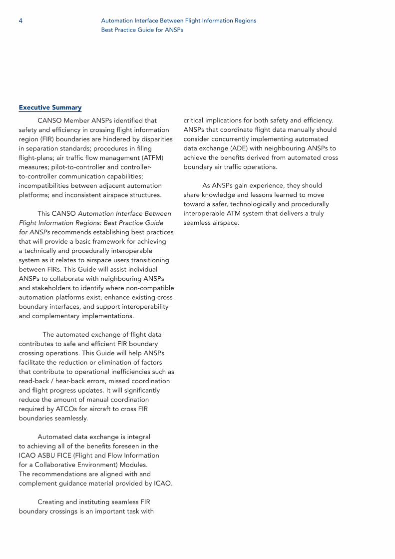
When ANSPs assessed the results from successful implementation of automation systems that interface with adjacent ATSUs, it was clear, from feedback by ATCOs, that the benefits gained were significant. Transitioning from manual coordination to automated data exchange significantly enhances safety and efficiency. The benefits are summarised in Table 1 below.
The three most prevalent applications used to provide ADE between ATM systems are: ATS (air traffic services) inter-facility data communications (AIDC), documented in the ICAO Pan Regional (NAT and APAC) Interface Control Document for ATS Interfacility Data Communications (PAN AIDC
ICD) (2013); On-line data interchange as described in EUROCONTROL Specification for On-Line Data Interchange (OLDI) (2010); and the common interface processing protocols detailed in the North American (NAM) Common Coordination Interface Control Document (ICD). The three applications; AIDC, OLDI and NAM, all utilise the flight data exchange model described in ICAO Document 4444, Procedures for Air Navigation Services: Air Traffic Management, (PANS-ATM) which is defined as three phases (see page 13 for further details):
— Notification — Coordination — Transfer of Control
Table 1. AIDC Summary of Benefits Table: ICAO Document 9750 Global Air Navigation Plan 2013-2028
Improved capacity Reduced ATCO workload and increased data integrity supports reduced separation. This translates directly to cross sector or boundary capacity flow increases.
Increased efficiency The reduced separation can also be used to more frequently offer aircraft flight levels closer to the flight optimum; in certain cases, this also translates into reduced en-route holding.
Improved global interoperability The use of standardised interfaces reduces the cost of development, allows ATCOs to apply the same procedures at the boundaries of all participating centres and border crossing becomes more transparent to flights.
Enhanced safety Greater accuracy of flight plan information enhances the ATCO’s ability to tactically plan for and properly control the flight.
Improved Cost Benefit Increase of throughput at ATSU boundary and reduced ATCO workload will outweigh the cost of FDPS software changes. The business case is dependent on the environment.
Automation Interface Between Flight Information Regions
Best Practice Guide for ANSPs

7
Figure 1. Flight data exchange between ATSUs using AIDC.
The automated exchange of flight data facilitates quick and accurate exchange of information and delivers safety and efficiency benefits for ANSPs and aircraft operators. The major benefits are:
— Reduced workload for ATCOs — Reduction of read-back and hear-back
errors due manual coordination — Reduction of gross navigational errors
and large height deviations which may have occurred due to ATCO-to-ATCO coordination errors
— Facilitation of operational initiatives such as user preferred routes (UPR) and dynamic airborne reroute procedure (DARP).
Automated data exchange is no longer only a desirable feature but is now becoming a necessity where the separation minima between flights are reduced and flight paths are becoming more flexible and user-centric. The seamless transition of flights across FIR boundaries with reduced lateral and longitudinal separation and flight paths like flex tracks, UPRs, DARPs require quick and accurate exchange of data across FIR boundaries. This is best achieved through automated exchange of flight data rather than manual coordination because:
— Coordination can be achieved in fewer
steps and is almost instantaneous — There is more consistency and certainty
in automated data exchange — Automated data exchange may allow the
system to perform handoffs electronically, thus eliminating the need to coordinate handoffs manually
1.1 Steps Involved in Manual CoordinationIn an en route environment, sectors may
be staffed by up to three separate positions. The nomenclature for these positions varies by region/ATSU, but for the purposes of this guidance, they will be referred to as executive controller, planning controller, and coordinator.
— The executive controller handles air to ground communications, provides weather information, gives traffic advisories, and issues clearances to flights. The executive controller requires a high level of situational awareness of flight path, flight levels, sector saturation, and flight time estimates
— The planning controller monitors the frequency and, in coordination with the executive controller, plans for profiles of the flights at the transfer of control point (TCP)
8
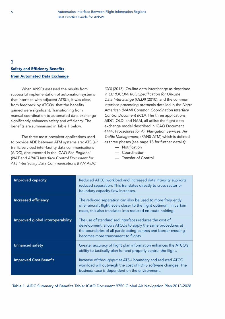
— The coordinator performs intra-facility and inter-facility coordination. In the case of manual coordination, when data such as the estimated time and flight level at the TCP have been confirmed by the executive and planning controller, the coordinator takes necessary steps to coordinate this data with other ATCOs via voice. The coordinator at the receiving end manually inputs the flight data
(not necessarily directly) into the ATM automations system.
The majority of tasks in ADE applications are performed by the ATM systems. In contrast, manual coordination requires human input at every step. The steps required in manual coordination take more time than that of ADE. Figure 2 contrasts the differences between manual and ADE:
Manual Coordination Automated Data Exchange
Figure 2. Illustrates an example of steps utilised by ATCOs to effect successful manual coordination and in contrast, the steps initiated to effect successful automated exchange.
Automation Interface Between Flight Information Regions
Best Practice Guide for ANSPs

9
Moreover, in ADE processes the originating ATM system can effect coordination with multiple receiving systems simultaneously.
Applications like AIDC and OLDI relieve the coordinators of the work intensive manual tasks and leave only some ancillary tasks for the coordinators to perform; thus reducing the requirement of human resources. If a FIR with four sectors required four coordinators, through automation, this might be reduced one to two coordinator positions.
When quicker and more accurate automated data is exchanged, ATCOs are able to increase situational awareness, reduce workload, and thus ensure a safer and more efficient operation.
Possible Errors in Manual Coordination Possible Errors in ADE
Wrong update in the system at transmitting end Wrong update in the system
Flight plan error Flight plan error
Error in reading/transmitting the data N/A
Error in receiving/hearing the data N/A
Error in noting down the data N/A
Wrong update in the system at receiving end N/A
The chances of errors are thus less in automated flight data exchange and the integrity of data is higher. The list of possible errors in each case is given below.
Other than reducing errors and thus improving safety, the ADE applications like OLDI and AIDC also help improve efficiency through quicker coordination. The data exchange is nearly instantaneous as the messages are exchanged through aeronautical fixed telecommunications network (AFTN) based on message priority. Whereas, in manual coordination, the process requires much more time due to factors such as engaged telephone lines, ATCOs being busy with other tasks, typing or writing of data etc.
Table 2. Potential errors associated with manual and automated coordination.
10
2
Relationship to ICAO ASBU Framework
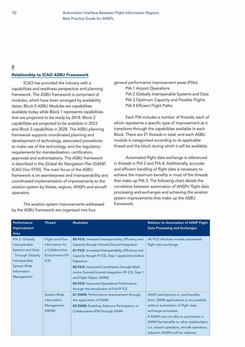
ICAO has provided the industry with a capabilities and readiness perspective and planning framework. The ASBU framework is comprised of modules, which have been arranged by availability dates; Block 0 ASBU Modules are capabilities available today while Block 1 represents capabilities that are projected to be ready by 2018. Block 2 capabilities are projected to be available in 2023 and Block 3 capabilities in 2028. The ASBU planning framework supports coordinated planning and development of technology, associated procedures to make use of the technology, and the regulatory requirements for standardisation, certification, approvals and authorisations. The ASBU framework is described in the Global Air Navigation Plan (GANP, ICAO Doc 9750). The main focus of the ASBU framework is on seamlessness and interoperability and coordinated implementation of improvements to the aviation system by States, regions, ANSPs and aircraft operators.
The aviation system improvements addressed by the ASBU framework are organised into four
general performance improvement areas (PIAs):PIA 1 Airport OperationsPIA 2 Globally Interoperable Systems and DataPIA 3 Optimum Capacity and Flexible FlightsPIA 4 Efficient Flight Paths
Each PIA includes a number of threads, each of which represents a specific type of improvement as it transitions through the capabilities available in each Block. There are 21 threads in total, and each ASBU module is categorised according to its applicable thread and the block during which it will be available.
Automated flight data exchange is referenced in threads in PIA 2 and PIA 4. Additionally, accurate and efficient handling of flight data is necessary to achieve the maximum benefits in most of the threads that make up PIA 3. The following chart details the correlation between automation of ANSPs’ flight data processing and exchanges and achieving the aviation system improvements that make up the ASBU framework.
Performance
Improvement
Area
Thread Module(s) Relation to Automation of ANSP Flight
Data Processing and Exchanges
PIA 2: Globally
Interoperable
Systems and Data
‐ Through Globally
Interoperable
System Wide
Information
Management
Flight and Flow
Information for
a Collaborative
Environment (FF
ICE)
B0-FICE: Increased Interoperability, Efficiency and
Capacity through Ground-Ground Integration
B1-FICE: Increased Interoperability, Efficiency and
Capacity though FF ICE, Step 1 application before
Departure
B2-FICE: Improved Coordination through Multi-
centre Ground-Ground Integration (FF ICE, Step 1
and Flight Object, SWIM)
B3-FICE: Improved Operational Performance
through the Introduction of Full FF ICE
All FICE Modules involve automated
flight data exchange
System-Wide
Information
Management
(SWIM)
B1-SWIM: Performance Improvement through
the application of SWIM
B2-SWIM: Enabling Airborne Participation in
Collaborative ATM through SWIM
ANSP participation in, and benefits
from, SWIM applications is not possible
without automation of flight data
exchange processes.
If ANSPs are not able to participate in
SWIM the benefits to other stakeholders
(i.e. airport operators, aircraft operators,
adjacent ANSPs) will be reduced.
Automation Interface Between Flight Information Regions
Best Practice Guide for ANSPs

11
Performance
Improvement
Area
Thread Module(s) Relation to Automation of ANSP Flight
Data Processing and Exchanges
PIA 3: Optimum
Capacity and
Flexible Flights –
Through Global
Collaborative ATM
Network
Operations
B0-NOPS: Improved Flow Performance through
Planning based on a Network Wide view
B1-NOPS: Enhanced Flow Performance through
Network Operational Planning
B2-NOPS: Increased user involvement in the
dynamic utilization of the Network
B3-NOPS: Traffic Complexity Management
ANSP participation in, and benefits
from, a network-wide view will be less
possible without automation of flight
data exchange.
If ANSPs are not able to fully participate
in network operations the benefits
to other stakeholders (i.e. airport
operators, aircraft operators, adjacent
ANSPs) will be reduced.
PIA 4: Efficient
Flight Path
– Through
Trajectory‐based
Operations
Continuous
Climb
Operations
B0-CCO: Improved Flexibility and Efficiency in
Departure Profiles - Continuous Climb Operations
(CCO)
Automated processing of flight data
enhances the ability for ANSPs to
extract aircraft capabilities from the
flight plan to facilitate performance-
based operations.
Automated flight data exchanges ensure
that complete flight data, including all
aircraft capabilities, are provided to
subsequent ANSPs.
If an ANSP does not forward all flight
data to downstream ANSPs that support
performance-based operations, they
and aircraft operators may not benefit
from their investments in supporting
technology and avionics.
Continuous
Descent
Operations
B0-CDO: Improved Flexibility and Efficiency in
Descent Profiles (CDO)
B1-CDO: Improved Flexibility and Efficiency in
Descent Profiles (CDOs) using VNAV
B2-CDO: Improved Flexibility and Efficiency in
Continuous Descent Profiles (CDOs) Using VNAV,
required speed and time at arrival
Trajectory-Based
Operations
B0-TBO: Improved Safety and Efficiency through
the initial application of Data Link En-Route
B1-TBO: Improved Traffic Synchronization and
Initial Trajectory-Based Operation
B3-TBO: Full 4D Trajectory-based Operations
Table 3. Relationship between automation data exchange and the ASBU framework.

12
3
Implementation Opportunities
There are many circumstances that create opportunities to implement, modify, or enhance ADE between neighbouring ANSPs. Examples of the circumstances include changing the ATS being provided in the FIR boundary area and replacing or modifying a flight data processing system. Safety concerns can drive the change to an existing system.
3.1 Increase Safety through Accurate Flight Plan Information:
The actual, or potential, root causes of operational errors should be identified as the result of an ANSP’s safety management system (SMS). A record of potential hazards provides an opportunity to develop mitigations to the specific issues being encountered during the exchange of flight data between ANSPs. Such information can identify safety benefits that could be realised by automating flight data exchanges. It can also aid in identifying areas where existing automation needs to be enhanced. SMS data often contributes to efficiency assessments, delineating the time and resources required to identify and correct errors, or to prevent errors from occurring when there are known weaknesses in the data exchange processes.
ANSPs need to be aware that data exchange issues, or practices, at one interface may affect subsequent interfaces. Awareness of how this may affect other ANSPs and/or interfaces needs to be maintained throughout the change process. To ensure the implementations remains on track, each change should be benchmarked against the safety case and the mitigations contained within it.
3.2 Changing the ATS in the FIR Boundary AreaWhen the services provided to flights within
an airspace volume are being changed, ANSPs will often begin making operational use of flight data that previously was not relevant. One example is
the introduction of performance-based operations that necessitates the knowledge of a flight’s performance-based navigation (PBN) status and specific equipage.
In such cases, ANSPs may need to change the methods used to exchange data to ensure that the required data is being provided correctly and at the required time. They may also need to implement new processes to ensure that updates to a flight’s equipage status, as indicated in the flight plan, are passed on.
ATS changes may also require changes to the flight data that should be exchanged. For example, if ATS surveillance services are being introduced, the ANSPs would need to exchange more precise estimate data, including updates, to enable automated handoffs or identification of the flight by the receiving ANSP.
3.3 Making Changes to the Flight Data Processing System
The most obvious opportunity to implement or enhance the automation of ADE occurs when changes are being made to the flight data processing system (FDPS) itself. It is at this time that all factors need to be considered to determine which direction the ANSP may take for the system change (e.g. field a new system, upgrade current system, change current system parameters, etc.).
This is a critical step in the evolution of an ANSP’s flight data processing/exchange lifecycle. It is here that the safety, business, and operation benefits cases are developed. This is the time that coordination with other ANSPs begins to take place to determine interface requirements and the development of new Letters of Agreement (LOA) practices and contents.
Automation Interface Between Flight Information Regions
Best Practice Guide for ANSPs

13
4
Interface Options and Considerations
4.1 Overview In pursuing the goal of seamless automation,
safety and efficiency interests extend beyond the borders of our airspace and systems. Traffic flows and transition between oceanic, en route and terminal airspace are factors that should be included as system and capability selection factors. This Guide is one source of information to aid in the analysis of individual ANSP situations and temper decisions with those lessons already learned locally and internationally to formulate an ‘executable’ interface strategy for successful implementation of automated data exchange (ADE).
Increasing traffic between FIRs drives the need to improve the efficiency and accuracy of information being exchanged between ATSUs. Developing a harmonised process, and defining protocols for exchanging cross-border data between multiple States, territories, and / or international organisations within, and across, regions is critical to achieving efficiency through automation.
The following information is provided to show the type of current, and near term, ADE initiatives that either have, or are expected to, evolve into successful interfaces. An automated communications and data interchange infrastructure significantly reduces the need for verbal coordination from ATSUs. AIDC, or similar automation, provides the means to harmonise ADE between ATSUs providing ATS in adjacent FIRs controlled by different ANSPs. As stated in ICAO Document (Doc) 9464, Manual of Air Traffic Services Data Link Applications, (paragraph 8.2):
“The AIDC application exchanges information between ATSUs in support of critical air traffic control (ATC) functions, including notification of flights approaching an FIR boundary,
coordination of boundary-crossing conditions, and transfer of control.”
Support for bilateral solutions and stakeholder collaboration is essential to ensure automation compatibility is maintained as interface systems evolve. Solutions must provide extensible system compatibility across all airspace boundaries. An interface consists of a defined set of messages, which describe consistent transfer conditions using electronic means across ATSU boundaries. The interface requires the implementation of the AIDC message set in the flight data processing systems of all the involved ATSUs, and the establishment of LOAs between these units, which establishes the appropriate parameters. Our collective ability to effectively integrate new technologies reduces the time required for ATCO tasks rather than simply increasing the number of tasks required of them. A communications and data interchange infrastructure significantly reduces the need for verbal coordination between ATSUs delivering more efficient and safer air traffic services. ICAO Doc 9464 Manual of Air Traffic Services Data Link Applications (paragraph 8.3) defines the following:
“AIDC defines messages which are related to three phases of coordination as perceived by an ATSU:
— Notify Phase, in which the aircraft trajectory and any changes may be conveyed to an ATSU from the current ATSU prior to coordination;
— Coordinate phase, in which the aircraft trajectory is coordinated between two or more ATSUs when the flight approaches a common boundary; and
— Transfer phase, in which communications and executive control authority is transferred from one ATSU to another.”
When flights that are being provided with air traffic services are transferred from one ATSU to the next via automation, safety is enhanced. It
14
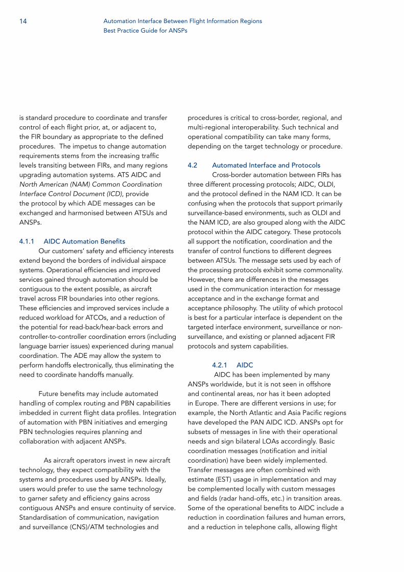
is standard procedure to coordinate and transfer control of each flight prior, at, or adjacent to, the FIR boundary as appropriate to the defined procedures. The impetus to change automation requirements stems from the increasing traffic levels transiting between FIRs, and many regions upgrading automation systems. ATS AIDC and North American (NAM) Common Coordination Interface Control Document (ICD), provide the protocol by which ADE messages can be exchanged and harmonised between ATSUs and ANSPs.
4.1.1 AIDC Automation Benefits Our customers’ safety and efficiency interests
extend beyond the borders of individual airspace systems. Operational efficiencies and improved services gained through automation should be contiguous to the extent possible, as aircraft travel across FIR boundaries into other regions. These efficiencies and improved services include a reduced workload for ATCOs, and a reduction of the potential for read-back/hear-back errors and controller-to-controller coordination errors (including language barrier issues) experienced during manual coordination. The ADE may allow the system to perform handoffs electronically, thus eliminating the need to coordinate handoffs manually.
Future benefits may include automated handling of complex routing and PBN capabilities imbedded in current flight data profiles. Integration of automation with PBN initiatives and emerging PBN technologies requires planning and collaboration with adjacent ANSPs.
As aircraft operators invest in new aircraft technology, they expect compatibility with the systems and procedures used by ANSPs. Ideally, users would prefer to use the same technology to garner safety and efficiency gains across contiguous ANSPs and ensure continuity of service. Standardisation of communication, navigation and surveillance (CNS)/ATM technologies and
procedures is critical to cross-border, regional, and multi-regional interoperability. Such technical and operational compatibility can take many forms, depending on the target technology or procedure.
4.2 Automated Interface and Protocols Cross-border automation between FIRs has
three different processing protocols; AIDC, OLDI, and the protocol defined in the NAM ICD. It can be confusing when the protocols that support primarily surveillance-based environments, such as OLDI and the NAM ICD, are also grouped along with the AIDC protocol within the AIDC category. These protocols all support the notification, coordination and the transfer of control functions to different degrees between ATSUs. The message sets used by each of the processing protocols exhibit some commonality. However, there are differences in the messages used in the communication interaction for message acceptance and in the exchange format and acceptance philosophy. The utility of which protocol is best for a particular interface is dependent on the targeted interface environment, surveillance or non-surveillance, and existing or planned adjacent FIR protocols and system capabilities.
4.2.1 AIDC AIDC has been implemented by many
ANSPs worldwide, but it is not seen in offshore and continental areas, nor has it been adopted in Europe. There are different versions in use; for example, the North Atlantic and Asia Pacific regions have developed the PAN AIDC ICD. ANSPs opt for subsets of messages in line with their operational needs and sign bilateral LOAs accordingly. Basic coordination messages (notification and initial coordination) have been widely implemented. Transfer messages are often combined with estimate (EST) usage in implementation and may be complemented locally with custom messages and fields (radar hand-offs, etc.) in transition areas. Some of the operational benefits to AIDC include a reduction in coordination failures and human errors, and a reduction in telephone calls, allowing flight
Automation Interface Between Flight Information Regions
Best Practice Guide for ANSPs

15
data operators the time to prioritise work. Bilateral LOAs should address the subset of messages used and their associated procedures. The messages are conveyed over automated message handling system (AMHS)/internet protocol (IP) or AFTN.
The AIDC functionality described in the PAN AIDC ICD provides guidance for messaging
in non-surveillance environments, coordination and system non-surveillance functionality as is used in oceanic operations. Supplemental capabilities such as automatic dependent surveillance-contract (ADS-C) and controller-pilot data link communications (CPDLC) provide the needed communication and position information needed in many oceanic non-surveillance areas.
Figure 3. U.S. International Interfaces
United States Flight Information Region Boundary Crossings
Neighboring FIR CY 2012 CY 2013 CY 2014 CY 2015
Canada FIRs 2,489,122 2,513,329 2,556,999 2,409,602
Mexico FIRs 390,280 402,499 413,821 407,738
Habana 230,212 233,922 241,641 242,794
Japan 125,961 130,515 133,490 131,709
Nassau CTA 120,814 113,279 117,088 114,903
Santo Domingo 88,751 92,715 101,822 97,591
Piarco 79,640 81,027 85,000 81,667
Santa Maria 72,281 73,459 76,726 75,750
Port Au Prince 46,090 47,978 49,886 45,792
Russia FIRs 39,665 39,894 40,365 41,409
Maiquetia 11,948 13,536 13,338 13,082
Port Moresby 10,721 10,672 10,770 10,204
Auckland Oceanic 6,463 7,250 7,580 7,936
Curacao 6,054 5,941 6,519 6,848
Manila 5,794 5,565 6,184 6,550
Nadi 2,703 2,941 3,104 2,839
Tahiti 2,984 2,571 2,791 2,630
Nauru 552 609 618 711
Ujung Pandang 255 224 235 219
Grand Total 3,609,476 3,664,647 3,750,889 3,699,974
Table 4. Reflects the number of U.S. boundary crossings per annum.
Sour
ce: F
eder
al A
viat
ion
Ad
min
istr
atio
n

16
4.2.1.1 AIDC in Airservices Australia’s AirspaceImplementation. Airservices Australia has
implemented AIDC messaging in both the Brisbane and Melbourne FIRs. Although the Brisbane and Melbourne FIRs use an identical platform, the systems are semi-standalone and AIDC messaging is used to maintain flight plans and effect coordination. AIDC exchanges are also made to/from:
— Mauritius — Johannesburg Oceanic — Ujung Padang — Nadi — Oakland — Auckland Oceanic
The South Pacific region has seen widespread implementation of AIDC for cross FIR coordination whereas the Indian Ocean region has seen only sporadic implementation. AirNav Indonesia, which has already established AIDC in its Ujung Padang FIR, plans to implement AIDC in its Jakarta FIR in the near future. Airservices Australia, Airport and Aviation Services (Sri Lanka), and Maldives Airports Company have undertaken some preliminary testing across their shared FIR boundaries, which highlighted the importance of the involvement of technical staff during testing and implementation. As part of the implementation, a mechanism for real-time feedback should be established to diagnose and resolve technical problems, as well as confirm successful message transmission and reception.
Inter-FIR messaging. Airservices Australia’s Thales Eurocat X platform integrates oceanic, continental en route and approach cells within a FIR; therefore, no AIDC messaging is required between units within the Melbourne FIR, or within the Brisbane FIR.
Airservices Australia uses only a subset of the complete AIDC v3.0 message set in the Indian Ocean region. This message subset allows for limited use of AIDC – it updates the subsequent FIR on changes to flight plan information including cleared route, level and secondary surveillance radar (SSR) code, while automated handoffs
are made possible across some boundaries. Any changes to information occurring after the EST message is sent necessitates manual voice coordination over fixed communication lines.
Because of display limitations (some sectors in the Indian Ocean region are so large that they often cannot be displayed on a single ATCO air situation display), voice coordination is used across some boundaries as a supplementary ‘heads-up’ to the receiving sector. This voice coordination is cross-checked against the AIDC messaging received to ensure accurate transfer of information.
In the South Pacific region, a more advanced message set has been implemented. These messages allow for limited negotiation between units for changes after the coordination parameter and where denser traffic has necessitated smaller sectors that may be more easily displayed on an air situation display, truly voiceless coordination and non-radar handoffs have been implemented.
Within Airservices Australia. A similar message set is used between the Brisbane and Melbourne FIRs, which permits voiceless coordination and radar/non-radar handoffs between the two FIRs. Airservices Australia has based all automated messaging on the PAN AIDC ICD; however, some ICD message elements are not supported. When an aircraft’s clearance includes an element that is not supported (such as weather deviations off track), manual voice coordination over fixed communication lines is effected to ensure that the receiving FIR has all the details.
Protecting against coordination errors. Airservices Australia has implemented AIDC as a way of protecting against errors in the exchange of flight plan information – either by entirely removing the reliance on humans interpreting data (implementing a voiceless coordination environment) or by using the flight information sent in AIDC messaging as a base on which to cross-check voice coordinated flight information.
Automation Interface Between Flight Information Regions
Best Practice Guide for ANSPs

17
4.2.2 OLDIThe system of automated coordination used
by EUROCONTROL area control centres (ACCs) is OLDI. The use of automation is not mandated but where automation is agreed upon, it must be as defined in the EUROCONTROL OLDI specification. This defines the system requirements required to support OLDI and the usage and content of OLDI messages. There are a large number of OLDI message sets defined across the range of functions. The number of these message sets used on an interface is by bilateral agreement between OLDI partners.
OLDI messages are exchanged between ATC units to provide for the exchange of coordination details and transfer of control information. Coordination is achieved against predefined coordination points (COP). The basic information consists of the aircraft identification, COP, time, flight level and SSR code. Additional information supported by the message set can be exchanged by agreement.
All EUROCONTROL ACCs now have OLDI connections with their adjacent partners, including many on the EUROCONTROL boundary such as North Africa. OLDI is also used for internal communication between FIRs or units. The message set has been extended to cover CPDLC and network flow messages.
ATC units use OLDI for the purpose of achieving:
— The notification of flights — The coordination required prior to the
transfer of flights from one unit to the next
— The co-ordination between civil and military ATC
— Situational awareness — The transfer of communication of such
flights — Support to air-ground data link — Coordination between ACCs and oceanic
control centres.
OLDI and AIDC have very similar message sets for most messages. However, there are some differences between the two protocols. OLDI has a larger message set but does not have an equivalent of the AIDC track definition message (TDM) since Europe relies on the initial flight plan processing system (IFPS), and OLDI has messages for both Future Air Navigation Systems (FANS 1/A) and Aeronautical Telecommunications Network (ATN B1) functions.
Despite the OLDI specification, issues can arise where one of the systems on a boundary cannot fully meet the requirement. This can result in problems of valid data being overwritten with incorrect data. This issue is addressed by an interoperability test for all changes.
It is planned that the Single European Sky ATM Research (SESAR) systems being deployed will be able to exchange flight objects, which will move transfer of control beyond OLDI. This has the potential to support more flexible boundaries in the knowledge that all parties have the same view of the flight information.
Figure 4. AIDC use in Airservices Australia’s airspace.
Sour
ce: A
irse
rvic
es A
ustr
alia

18
Sour
ce: N
ATS
4.2.3 NAM-ICD In North America the NAM ICD is mostly
used in domestic operations and domestic/oceanic transition areas; often, cross-border operations do not fit neatly into one or the other category. Many systems today will allow interface protocols to be tailored to a particular interface: NAM or AIDC. System providers constructing their interface capabilities must take into account the need for scalable requirements and flexibility, as adjacent FIRs will have different ATC systems. AIDC, NAM, and OLDI support the notification, coordination, and the transfer of communications and control functions to different degrees between ATSUs. Full AIDC capability also supports extended equipment capabilities in time and distance based operations where different separation minima are being used in adjacent airspace. The NAM ICD has automated radar handoff messaging definitions within the document as a goal of cross-border interoperability evolution. OLDI is used extensively in the European region and NAM messaging is used throughout North America. The NAM protocol provides the advantage of extensibility to handoff and point-out functionality, enhancing a positive controlled radar environment.
Compatibility management between existing and or emerging international automation systems
is essential to optimise capabilities and meet stakeholder needs. For example, the centralised geographic position of the United States (U.S.) requires interface collaboration to ensure that compatibility is maintained with ANSPs with U.S. boundaries, and with those wanting to implement new interfaces or enhance existing interfaces. Interfaces with the Dominican Republic, Bahamas, and an upgrade to NAM with Cuba are examples of active projects that are being worked to provide the benefits associated with ADE. The U.S. and NAM ICD Member States have realised automation gains that provide significant safety and efficiency benefits. A recent example of extending automation capability in the North American region is the Miami Air Route Traffic Control Center (KZMA) 2011 automation interface with the Cuba’s Havana ACC (MUFH). It has been estimated that a 50 percent reduction in workload for ATCOs working the border sectors at KZMA has been achieved with the operational implementation of NAM ICD Class 1 ADE. In most NAM environments, radar is the operational norm and non-radar the exception; in many traditional AIDC interfaces non-radar or non-surveillance is more the norm and radar/surveillance is the exception.
Figure 5. Depiction of the extent of OLDI rollout.
Automation Interface Between Flight Information Regions
Best Practice Guide for ANSPs
19
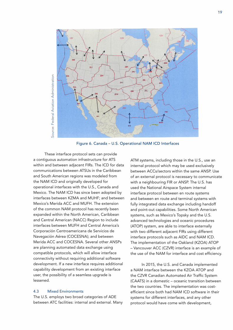
These interface protocol sets can provide a contiguous automation infrastructure for ATS within and between adjacent FIRs. The ICD for data communications between ATSUs in the Caribbean and South American regions was modeled from the NAM ICD and originally developed for operational interfaces with the U.S., Canada and Mexico. The NAM ICD has since been adopted by interfaces between KZMA and MUHF; and between Mexico’s Merida ACC and MUFH. The extension of the common NAM protocol has recently been expanded within the North American, Caribbean and Central American (NACC) Region to include interfaces between MUFH and Central America’s Corporación Centroamericana de Servicios de Navegación Aérea (COCESNA); and between Merida ACC and COCESNA. Several other ANSPs are planning automated data exchange using compatible protocols, which will allow interface connectivity without requiring additional software development. If a new interface requires additional capability development from an existing interface user, the possibility of a seamless upgrade is lessened.
4.3 Mixed Environments The U.S. employs two broad categories of ADE between ATC facilities: internal and external. Many
ATM systems, including those in the U.S., use an internal protocol which may be used exclusively between ACCs/sectors within the same ANSP. Use of an external protocol is necessary to communicate with a neighbouring FIR or ANSP. The U.S. has used the National Airspace System internal interface protocol between en route systems and between en route and terminal systems with fully integrated data exchange including handoff and point-out capabilities. Some North American systems, such as Mexico’s Topsky and the U.S. advanced technologies and oceanic procedures (ATOP) system, are able to interface externally with two different adjacent FIRs using different interface protocols such as AIDC and NAM ICD. The implementation of the Oakland (KZOA) ATOP – Vancouver ACC (CZVR) interface is an example of the use of the NAM for interface and cost efficiency.
In 2015, the U.S. and Canada implemented a NAM interface between the KZOA ATOP and the CZVR Canadian Automated Air Traffic System (CAATS) in a domestic – oceanic transition between the two countries. The implementation was cost-efficient since both had NAM ICD software in their systems for different interfaces, and any other protocol would have come with development,
Figure 6. Canada – U.S. Operational NAM ICD Interfaces
Sour
ce: F
eder
al A
viat
ion
Ad
min
istr
atio
n

20
testing and training costs and implementation complexities. A similar interface is being considered for implementation on the North Atlantic boundary between the U.S. New York ACC (KZNY) ATOP and the Canadian Moncton ACC CAATS using the same NAM ICD protocol.
In 2010, MUFH and KZMA agreed to pursue the NAM interface between the facilities using the multiple U.S. – Mexico interfaces as a model for the Cuba effort. Cuba internally developed the software in accordance with the NAM ICD and was committed to the effort and providing technical proficiency. The interface was implemented in December 2011. By virtue of making the proper planning decisions in the KZMA – MUFH interface, Mexico and Cuba were able to extend their interface efforts by implementing a similar interface between Merida – MUFH only one month later. This was a significant accomplishment for the NACC Region, and one that continues to have increasing benefits. The extension of the NAM interface in 2015 to include COCESNA (Honduras) to MUFH and COCESNA to Mexico’s Merida ACC was assisted by the lessons learned and subject matter knowledge from the implementation of the MUFH – KZMA interface.
Adjacent airspace with manual surveillance-to-surveillance operations prompted the use of a regionally compatible protocol and the NAM ICD effectively supported that choice. The selected NAM protocol message sets were a scalable solution, allowing the incremental implementation of capabilities and message sets. Additionally, the U.S. had the expertise to assist in the implementation of a NAM ICD based interface, which was already operational with multiple interfaces between the U.S., Canada, and Mexico.
4.4 Considerations Seeking to ensure continuous safety improvement, and air navigation modernisation, ICAO has developed the ASBU framework as a strategic
systems-based approach to planning and implementation. The ICAO Global Air Navigation Plan (GANP) Doc 9750 ICAO states that the ASBU framework “defines a programmatic and flexible global systems engineering approach allowing all States to advance their Air Navigation capacities based on their specific operational requirements”. The Module B0-FICE outlines improvements in coordination between ATSUs by using AIDC. EUROCONTROL uses OLDI to satisfy AIDC requirements. The AIDC and the OLDI are integrated protocols to coordinate flight data between ATSUs to satisfy the basic coordination of flight notification, coordination and transfer of control. Additional options like pre-departure coordination, civil-military coordination and air-ground data link for forwarding log-on parameters are available in the OLDI.
OLDI has been in operational use for more
than twenty years in Europe and for more than four years in the United Arab Emirates. During the ICAO Middle East (MID) Region ATN-IPS WG5 meeting, Cairo, Egypt 11-13 March 2013, it was noted that the majority of States in the MID region have either implemented OLDI or are planning to implement OLDI. Therefore, the meeting agreed that OLDI implementation should be considered and accepted as a regional variation of AIDC implementation as was the case in the European region. The MID Region ATN-IPS WG5 meeting further agreed that if both AIDC and OLDI are implemented, then it will be a bilateral issue and some States that are interfacing with adjacent regions may be required to support and implement dual capabilities (AIDC and OLDI).
A further consideration is the quality of flight data and its impact on ADE. Capabilities need to address flight data and how it works with resident automation systems as well as adjacent facility automation. Ensuring the quality of data involves understanding how flight data systems interact with the ADE system and how the message may
Automation Interface Between Flight Information Regions
Best Practice Guide for ANSPs

21
be modified or changed by the involved systems. Differences must be corrected, accommodated, or mitigated to minimise the instances of rejection to an error queue and maximise system acceptance of the flight data. Acknowledging the differences in how systems process data is imperative to proper flight processing.
The quality of filed flight plans is an issue to be aware of when implementing new interfaces or updating existing interfaces. This issue highlights a quality control problem that already existed within the manual system but is now apparent because automation demands greater adherence to standards and is less tolerant in processing incorrect data and data with errors. Flight plans received before the interface was automated were processed manually. Now they are received by automated systems, which are less forgiving of errors in format and data integrity. Many errors in filed flight plans, which have been absorbed for years within a manual system, become problematic in the automated system when filed information is not in accordance with defined ICAO guidelines. Additionally, multiple flight plans received for the same flight must be manually filtered to ensure the correct data is being forwarded by the computer system to subsequent receiving facilities.
Conflicting information between flight plans filed at the departure airports and those filed by the airlines are often seen. KZMA has been dealing with this type of flight plan issue for years, but it is new to the MUFH automation, which has to deal with conflicting data and resolve any flight plan errors. Any solution must include quality control initiatives for filers and filing services to ensure the transmitted data conforms to the provisions detailed in the PANS-ATM ICAO Doc 4444. Additionally, a collaborative solution to reduce the number of errors in flight plan filing and instances of multiple flight plans for the same flight must be agreed by involved stakeholders, including the ANSP, ICAO, IATA, the filers, and automated system
users. The solution will not be easy but the result will be a better product for the automated systems, which will enhance safety and efficiency and support a seamless worldwide flying environment.
4.5 CPDLC and ADS-C Operations This section deals primarily with the FANS
1/A data link system. The ATN B1 system currently in use in Europe has the automated connection capability and does not use ADS-C.
Aircraft Logon and Flight Plan CorrelationTo ensure the accuracy of the flight plan
correlation process, all responses to an aircraft logon should be automated, such as the sending of a CPDLC connection request message (CR1) in response to the logon, and the establishment of ADS-C contracts.
To avoid rejection, or failed connections, an aircraft’s logon should only occur within the period when the associated flight plan is in the correct automation state to receive a logon. For data link-equipped aircraft entering the FIR from non-data link airspace, ANSPs should publish in Aeronautical Information Publication (AIP), or other local documentation, the time period prior to the boundary crossing in which a manual logon will be accepted. For example, “aircraft entering the […] FIR should not logon earlier than 30 minutes prior to the FIR boundary estimate”.
The correlation of the logon with the aircraft’s flight plan should also be automated, and should be based on both the aircraft’s call sign and registration, as a minimum.
Transfer of CPDLC ConnectionTo ensure that data link related transfers
occur consistently, and at agreed transfer points, all facets of the transfer process across FIR boundaries should be automated.
The first message to be sent in the transfer process is the next data authority message (NDA).

22
The purpose of the NDA is to notify the aircraft’s system of the four-character ICAO address of the next ATSU to send a CPDLC connection request to the aircraft. If the aircraft receives a connection request message from a different ICAO address, or if the aircraft receives a connection request before it has first received the NDA message (even if the sender is the correct ATSU), then the connection request will be rejected. The NDA should be sent at a time prior to the FIR boundary crossing that is sufficient to allow the connection process with the next ATSU to be completed prior to the boundary crossing point.
Following the NDA, the ATS facilities notification (AFN) contact advisory message (FN_CAD) is sent to the aircraft to instruct the avionics to logon to the next ATSU. Sending this message is commonly referred to as address forwarding. Due to the automatic response to the logon from the next unit, there should be sufficient interval between the automatic sending of the NDA and the FN_CAD (at least 60 seconds) to ensure that the aircraft receives the NDA message prior to the connection request message from the next unit.
The ATSU with the active CPDLC connection (known as the current data authority, or CDA) should endeavour to close all CPDLC dialogues before the transfer point. The end service message is sent at the transfer point, which is typically prior to the boundary crossing, so that the CPDLC connection is active with the next unit prior to the aircraft crossing the boundary. On receiving the end service message, the aircraft will disconnect from the current unit and any open message dialogues will be discarded.
Many ANSPs have linked the automated sending of the end service message to the AIDC transfer of control message / acceptance of control message (TOC/AOC) message exchange. The TOC is sent to the next unit to initiate the transfer. The end service message is then sent
Figure 7. Current FANS 1/A FIR transfer process Source: Thales Australia
automatically to the aircraft by the transferring system when the AOC is returned by the receiving unit. The linkage to the AIDC process ensures that the communications capability remains with the controlling authority until the receiving unit has accepted the transfer of control.
AIDC Version 3.0 has further improved the automation of the FANS 1/A CPDLC connection
Figure 8. Data link transfer completion incorporating AIDC (TOC/AOC).
Source: Thales Australia
Automation Interface Between Flight Information Regions
Best Practice Guide for ANSPs
23
transfer process. Currently in the FANS 1/A data link system, the receiving ground system is only notified that its CPDLC connection with the transferring aircraft has been activated on receipt of a downlink message from the aircraft.
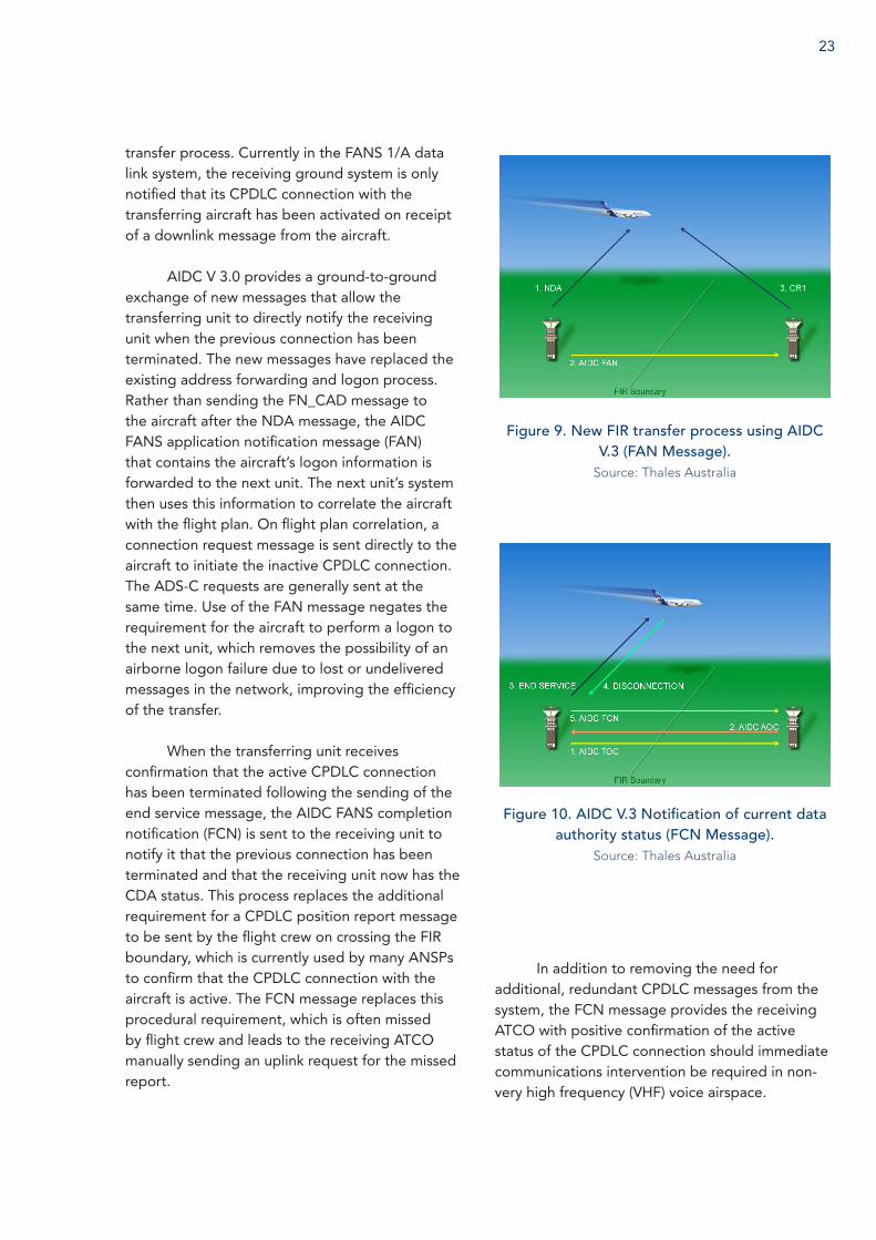
AIDC V 3.0 provides a ground-to-ground exchange of new messages that allow the transferring unit to directly notify the receiving unit when the previous connection has been terminated. The new messages have replaced the existing address forwarding and logon process. Rather than sending the FN_CAD message to the aircraft after the NDA message, the AIDC FANS application notification message (FAN) that contains the aircraft’s logon information is forwarded to the next unit. The next unit’s system then uses this information to correlate the aircraft with the flight plan. On flight plan correlation, a connection request message is sent directly to the aircraft to initiate the inactive CPDLC connection. The ADS-C requests are generally sent at the same time. Use of the FAN message negates the requirement for the aircraft to perform a logon to the next unit, which removes the possibility of an airborne logon failure due to lost or undelivered messages in the network, improving the efficiency of the transfer.
When the transferring unit receives confirmation that the active CPDLC connection has been terminated following the sending of the end service message, the AIDC FANS completion notification (FCN) is sent to the receiving unit to notify it that the previous connection has been terminated and that the receiving unit now has the CDA status. This process replaces the additional requirement for a CPDLC position report message to be sent by the flight crew on crossing the FIR boundary, which is currently used by many ANSPs to confirm that the CPDLC connection with the aircraft is active. The FCN message replaces this procedural requirement, which is often missed by flight crew and leads to the receiving ATCO manually sending an uplink request for the missed report.
In addition to removing the need for additional, redundant CPDLC messages from the system, the FCN message provides the receiving ATCO with positive confirmation of the active status of the CPDLC connection should immediate communications intervention be required in non-very high frequency (VHF) voice airspace.
Figure 9. New FIR transfer process using AIDC V.3 (FAN Message).
Source: Thales Australia
Figure 10. AIDC V.3 Notification of current data authority status (FCN Message).
Source: Thales Australia

24
5
Implementation Planning
5.1 Interface/System Implementation Planning When planning an interface with the
adjacent FIR, a full set of messages may not be needed to achieve ADE. Scalable interfaces, which can support incremental levels of capabilities using a reduced set of interface messages, provide for tremendous implementation flexibility and benefits, and helps to keep ATC and technical training at a manageable level. The training required for a full interface implementation can be overwhelming. Conversely, an incremental approach to implementation can allow for manageable, incremental training. Additionally, the incremental approach provides the opportunity to learn the system and make informed decisions on enhancements or system modifications based on operational need. This is especially beneficial when an ANSP is implementing a new system, which employs newer technology and capabilities. Both NAM ICD and AIDC have been used in reduced message set implementations.
Improper interface selection during the interface planning phase can cause issues which may prevent an interface from being implemented. Strategic planning for the demands of handling the issues which will occur during implementation is a must for successful transition. Defining the ANSP’s requirements must be an interactive process that begins with a task analysis that articulates each task the stakeholder must accomplish.
Identifying and eliminating the large deficiencies which exist prior to putting the interface in the operational environment is necessary to a successful implementation. While the operational environment might seem like the best test bed for a new interface, it is the worst place to discover the issues as impacts are magnified.
When analysing available lessons learned for the proposed interface, the operational
environment should always be examined in formulating the strategy for the project. Refer to Appendix B for an example implementation checklist. The following factors are among those that should be considered:
— A determination of which system protocols are already being used in bordering FIRs and how they are being used. Understanding the protocols that adjacent systems are capable of supporting can yield future benefits.
— It is important that decisions to implement automation are realistic and achievable. For example, if a significant systems investment is required by a potential interface partner in support of a unique adjacent interface, the effort may never happen.
— In order to provide the most effective automation between FIRs, operational environment matching with the proper automation protocol is needed to successfully field an interface.
— Relationships between airspace volumes to be served by ATC systems and the interfaces to be implemented must be analysed. Surveillance to surveillance, non-surveillance to non-surveillance or surveillance to non-surveillance should be examined when planning an interface. The CANSO Best Practice Guide to Crossing Flight Information Region Boundaries speaks to the complexities of surveillance to non-surveillance boundaries. Some examples within that best practice guide include the KZOA ATOP and CZVR CAATS in a domestic – oceanic transition area. That interface is now operational and offers some lessons learned.
— System needs, coupled with current and new system capabilities and or limitations, should also be factored into
Automation Interface Between Flight Information Regions
Best Practice Guide for ANSPs
the interface protocol decision. In a mixed environment of radar and non-radar the NAM ICD protocol can be used effectively. Additionally, partnering with an adjacent facility that already has operational interfaces using the same protocol can also lead to a successful, timely implementation. In the absence of FIR – FIR interface experience, regional expertise may be an option.
Creating the planning teamThe make-up of the planning team may
consist of many of the stakeholders identified in 5.1 as well as the project team. This team needs to:
— Agree the system to be implemented — Determine the training and
implementation requirements — Initiate safety management system
activities — Develop training (classroom, computer-
based, simulated, operational) — Draft procedures to be included in inter-
unit agreements — Conduct a post implementation review — Ensure that a mechanism is in place to
log implementation lessons learned.
5.2 StakeholdersThe benefits of collaboration between
aviation industry members have received increasing attention and therefore, it is important that ANSPs identify and consult with all stakeholders so that their requirements are addressed early in the implementation planning process. The affected stakeholders will depend on the local operational and regulatory environment in which the ANSP operates, but they may be categorised into internal and external entities.
Internal entities may include: — The ANSP’s ATCOs, air traffic control
assistants and flight data officers — Air traffic control supervisors
— Automation technicians — Adjacent ‘same ANSP’ ACC, approach
units, towers and flight information services
— Network managers, capacity/operations managers and aerodrome/flow managers
— Aeronautical information service officers.
External entities may include: — Airspace users (pilots, flight dispatchers
and airline operations centres) — Airport operators — ICAO regional offices, State civil aviation
authorities and other government agencies
— Adjacent ACCs, ANSPs, approach units, towers and flight information services
— Meteorology providers — Search and rescue authorities — Military
Ensuring that the needs of stakeholders are adequately addressed during the design and implementation stages supports system interoperability, avoids divergent or incompatible development between systems, and may identify opportunities to reuse or adapt existing tools and documentation. This may help avoid potentially costly and time-consuming post-implementation modifications to address unforeseen stakeholder requirements.
A number of stakeholders are represented or assisted by professional and industry bodies that provide their members with guidance for their participation in the implementation of new ATM automation systems and procedures. Consultation with these professional and industry bodies prior to beginning the implementation activities may be a useful way in which the ANSP can obtain stakeholder ‘buy-in’ to develop cross-organisational partnerships that can share information regarding working practices and system limitations. This will aid in identifying the
25

26
impact of system implementation on stakeholders in sufficient time to make necessary design changes before they cause constraints, operational risk, or increased cost.
5.3 Gap Analysis An ANSP may undertake a gap analysis
to investigate the differences between current capabilities and desired capabilities of the ATM system. The nature of the gap analysis will depend on the rationale for the implementation of the ATM system.
Current capability versus current requirements: When an ANSP faces increasing levels of flight data or where there are concerns due to the number of operational errors or precursor events related to flight data processing, it may be appropriate to conduct a gap analysis of the current ATM system capability versus the current requirements of the ATM system. Such a snapshot analysis may be used by an ANSP facing unforeseen and immediate challenges that require a rapid short-term response.
Current capability versus planned requirements: Where one or both ANSPs at an interface are planning to change the ATS being provided in the FIR boundary area or where one or both ANSPs are making changes to their flight data processing system.
Current capability versus future requirements: This analysis considers the future growth in air traffic as well as the changing demands of airspace users and should be undertaken in most cases so that the ATM system may operate to its intended life. It may be possible to provide for potential future requirements during an implementation or enhancement, thereby reducing future costs. These types of requirements are best identified in consultation with stakeholders, as part of a collaborative multi-state or regional planning process.
5.4 Task AnalysisThe implementation of a new ATM system
will very likely see changes to the way in which operational staff undertake their work (or their ‘method of working’); however, the significance of the change will depend on a number of factors including:
— The operational environment (en route, approach or tower)
— The nature of the existing ATM system — The nature of the new ATM system and — Coincident changes to the airways
system e.g. changes to air routes, air space sectorisation, PBN implementation, or changes by neighbouring ANSPs or airspace users
In order to determine exactly how the method of working of operational staff will be altered by the implementation of a new ATM system, the current method of working should be defined. This may be achieved by observing operational staff as they work with questioning used to clarify uncertainties and gain insight into human factor considerations. Such observation is beneficial to both the ANSP and the operational staff; indeed, the policy of the International Federation of Air Traffic Controllers’ Associations (IFATCA) is that operational ATCOs should be involved throughout the ATM system implementation process.1
With an understanding and comparison of the current versus anticipated ATCO method of working, training needs can then be identified. The training needs of each user group should be identified whenever there is a significant change to systems or procedures as a part of the ANSP’s change management activities. The ICAO Safety Management Manual (SMM) Doc 9859 describes the importance of change management as a part of a broader safety management system (see Chapter 6 of this document for further information on safety management including CANSO’s contribution); civil
Automation Interface Between Flight Information Regions
Best Practice Guide for ANSPs
1 IFATCA Technical and Professional Manual 2014

aviation authorities may impose additional change management requirements on the ANSP to those in the ICAO SMM.
Moving from a purely strip-based ATM system to a computer-based system may represent a significant change to ATCOs’ method of working, while for ANSPs that have already made the transition to a computer-based ACC, the transition from electronic strips to a strip-less system may represent a lesser change.
Reducing the size of the change from the existing system to the new system may reduce the training requirement; rather than moving from a paper strip-based system to a fully strip-less system, an ANSP may elect to implement electronic strips, which allows ATCOs to continue to use their well-practised method of working as they become more accustomed to operating in an electronic environment. An ANSP moving between electronic systems may, in consultation with the users and the vendor, implement a colour scheme in the new ATM system that is identical to the existing scheme.
It is important to note that while the training of ATCOs and other operational staff in new methods of working may consume significant resources, the training requirements should be viewed in the context of the projected safety, capacity, and efficiency gains that will be facilitated by a new or altered system. As stated above, the design and delivery of training for system users is an important component of the change management process. Proper training can ensure that operational staff use the ATM system to its full potential and allow the ANSP to realise the safety, capacity and/or efficiency gains that justify its investment.
5.5 System Requirements Defining the requirements of a new
or altered system is a critical step in the
implementation of a new or altered system that ensures that the requirements of both internal and external entities are met. System requirements must be defined in sufficient detail to ensure that systems engineers, who may not be experienced operational ATCOs, are able to provide a system that is fit for purpose, which will minimise the reworking of the system and therefore keep the development and implementation costs down.
Guidance for AIDC system requirements is given in ICAO Doc 9864 Manual of ATS Data-Link Operations. AIDC systems should attain requirements for availability, integrity, reliability and continuity. ICAO Doc 9864 specifies the following recommended values:
— Availability is the ability of the system to perform the functions for which it was intended, it is a percentage of the time the system is available with reference to the planned available time. The recommended value for availability is 99.996 percent
— Integrity refers to the probability that a correct message or part of a message is deemed to be erroneous. The acceptable value is 10–7
— Reliability of the AIDC system is the probability that the system will deliver messages without errors, this should be 99.9 percent
— Continuity is the probability of the system failing over a given period. AIDC systems must display a continuity of 99.9 percent
AIDC systems must possess a level of robustness that will ensure messages are delivered accurately to the correct ATSU and in the sequence in which they were sent; systems must recognise a hierarchical structure for priority messages and deliver accordingly. Each message must possess a unique identification with the associated response message containing the message identification of
27

28
the referenced message. Responsible personnel must be alerted within a fixed parameter when messages are rejected, not acknowledged or not received. System design must meet requirements for failures, facilitate a recovery process that is able to identify messages that are not acknowledged, maintain the integrity of message identification numbers and also there must be access to historical data
Correctly and thoroughly defining system requirements along the guidelines as suggested above is critical, however sometimes when a single ANSP is looking to replace its system, it considers the requirements to be internal, so very little coordination takes place with other stakeholders, especially adjacent ANSPs. The reasons for this lack of coordination may be many and varied, but to ensure harmonisation, systems requirements must be compatible. Defining the ANSP’s requirements must be an interactive process that begins with the task analysis. The task analysis will articulate each task that the stakeholder must accomplish to complete its work. The task analysis will derive the knowledge, data or alerts associated with each task, the system behaviours that support them, and the human machine interface that facilitates accomplishing the tasks as safely and effectively as possible.
In defining its own system requirements, an ANSP must consider the existing systems with which it will interact including those internal to the ANSP. Such systems include:
— Existing internal ATM systems (an adjoining FIR managed by the same ANSP)
— ATM systems operated by another ANSP — Notice to Airmen (NOTAM) and
meteorology providers — Systems of airports, airspace users and
other agencies which may receive or input data
While ATM systems continue to evolve, even the most modern ATM system does not function in isolation, and the movement of traffic across FIR boundaries may be significantly affected by the degree to which the ATM systems are able to communicate. The most advanced ATM system available will provide little support to ATCOs if there is no system communication across the FIR boundary to neighbouring ANSPs and they must instead manually coordinate all traffic using potentially unreliable telephone connections.
In order to facilitate system communication between systems, ANSPs should establish technical working relationships with their neighbouring ANSPs that facilitate the sharing of technical information relating to their operational systems. In addition to technical working relationships, higher-level relationships across FIR boundaries can foster a shared cross-ANSP understanding regarding future developments. By understanding the existing and future systems of their neighbours, an ANSP can include the need for backwards or forwards compatibility in its requirements definition.
An example of the need for such forward and backward compatibility is seen in AIDC, which exists in a number of iterations across the world. An ANSP may identify the latest version of AIDC in its requirements definition; however, if the ATM systems used in surrounding FIRs are of an earlier version or if surrounding FIRs do not use AIDC, but instead use a different system and do not plan to move to AIDC in the future, then the benefits of incorporating the latest version will be significantly limited.
5.6 StandardsAs described in Chapter 2, the ICAO GANP
presents a framework for harmonising avionics capabilities and the required ATM systems including automation; the ICAO ASBU framework provides a path for the global improvement and
Automation Interface Between Flight Information Regions
Best Practice Guide for ANSPs

29
harmonisation of ATM. ANSPs may use the ASBU framework to plan the future operability of their ATM systems. The CANSO booklet Introduction to the Aviation System Block Upgrade (ASBU) Modules provides ANSPs with an overview of the framework and the required integrated implementation processes of business case and needs and dependency analysis, which must be performed to select and implement the ASBU modules that best meet the operational needs of individual ANSPs.
The Global Operational Data Link Document (GOLD) has been adopted in the Asia Pacific, North Atlantic, European, South American, and African-Indian Ocean regions and is being developed for global application by ICAO. The GOLD combines the various regional standards to provide a globally harmonised standard for data link that addresses ATS data link service provision, operator readiness, and ATCO and flight crew procedures for the implementation of FANS 1/A and ATN B1 technologies.
ICAO has urged all states to implement routes and airport procedures in accordance with the ICAO PBN criteria2; therefore, it is highly desirable that new ATM systems facilitate PBN operations by airspace users. The ICAO PBN Manual (ICAO Doc 9613) and the CANSO PBN Best Practice Guide for ANSPs provide ANSPs with guidance on the implementation of PBN, while most states have published PBN Implementation Plans that provide local perspective.
The ICAO Global Aviation Safety Plan 2014-2016 (ICAO Doc 10004), although not directly addressing ATM automation systems, details safety performance enablers, which have been identified as enabling the objectives of the global aviation safety plan (GASP). The GASP safety performance enablers of standardisation, collaboration, resources and safety information exchange provide useful signposts to direct an ANSP’s efforts when
planning and implementing changes to ATM automation systems.
Where an ANSP makes long-term changes to its ATM system, it is important that provision is made for future changes to the ATM environment. SWIM – an integral part of the ICAO GANP – is a component of a number of ASBU modules. The ICAO Manual on System Wide Information Management (ICAO Doc 10039), which is under development at the time of this Guide’s publication – will provide an overview of the SWIM concept as well as an interoperability framework. The ICAO Manual on Air Traffic Management System Requirements (ICAO Doc 9882) and the ICAO Manual on Global Performance of the Air Navigation System (ICAO Doc 9883) provide ANSPs with an understanding of the delivery mechanisms for the ATM system envisaged in ICAO’s long-term ATM operational concept.
In addition to global documents, some ICAO regional offices have produced documents that define the regional strategic ATM plan and therefore the industry standards that the ATM system should support. An example of regional documentation is the ICAO Asia/Pacific Seamless ATM Plan 2013.3 The document defines the communication, navigation and surveillance standards that the Asia Pacific region will implement across the region up to 2018. By referring to such regional documentation during the planning phase, an ANSP may hope to better align the development of its ATM systems with its neighbours.
5.7 Assessing Possible SolutionsHistorically, the systems used by aircraft
to navigate and communicate with ATC retained significant commonality and VHF radios, VHF omni-directional radio range (VOR) navigation aids and the AFTN have achieved near universal use by airspace users and ANSPs. The development of modern systems for navigation
2 ICAO 36th Assembly, 2007, Resolution 36/23
3 http://www.icao.int/APAC/Documents/edocs/Asia%20Pacific%20Seamless%20ATM%20Plan%20V1.0.pdf

30
and communication saw the beginning of diversification, as multiple systems were developed to achieve similar outcomes such as improved navigation, communication and surveillance. It is imperative that ANSPs consider the implications of the communication, navigation and surveillance technology that they implement on system and ATCO interaction with neighbouring FIRs if they are to minimise the difficulties that can occur when flights cross FIR boundaries.
5.8 Implementation Lessons LearnedAirservices Australia, the FAA, Airports
Authority of India, NAV CANADA, and other ANSPs have had recent successes in implementing automation systems that interface with neighbouring ATSUs. The success didn’t come without pitfalls. In this section, the lessons learned in the implementation process, such as communication latency, performance and AIDC message success rate, phased implementation, and non-operational testing will be discussed.
Automation Interface Testing (offline): Testing is one of the most critical phases of the implementation process. It is in this phase where the latency of communications can be determined, and the success of logical accept messages can be measured. It should also be possible to determine the performance of the network (i.e., by the measurement of round trip times for AIDC message exchanges).
To ensure that there is minimal or no interruption to the provision of ATS services, where possible all automation interface testing should be conducted on a non-operational platform, e.g. a test facility that replicates the operational platform. The test facility should be equipped with a discrete AFTN address and communications link so that coordination messages may be sent to and from the platform without interfering with operational systems and flight data.
Automation Interface Testing (online): Having demonstrated satisfactory integrity and reliability on non-operational platforms, ANSPs may progress to testing automation interfaces on operational platforms using non-operational flight plan data. This should occur during low traffic periods and should be monitored closely to ensure that the testing does not affect the provision of air traffic services.
Other Testing Issues: A number of difficulties can arise when testing the automation interface between large neighbouring FIRs. Time differences can make finding the best time for testing difficult e.g. there are eight hours between local time in Johannesburg and Melbourne, which share an oceanic FIR boundary. In addition to time difficulties, communication difficulties can occur because unlike operational coordination lines, which are generally of high quality, technicians may communicate using a private automated branch exchange telephone switching system (PABX), which can be subject to interruption or be of low quality.
Ensuring Flight Plan Accuracy: Where certain messages have caused system or flight data discrepancies, it is desirable for an automation interface to have the capability of blocking those messages before they are incorporated into the ATM automation system. For example, to allow ATM automation systems to correctly process a flight plan, route truncation is often required, which may cause issues in subsequent FIRs if not processed correctly. An ANSP can benefit from the ability to block troublesome messages based on parameters such as originator, recipient and message type.
Cyclic Redundancy Check (CRC): Ensure that the CRC being used by the AIDC application is correct. AIDC messaging uses the CRC-CCITT algorithm, which has a number of variations; the correct variation for AIDC use is XModem.
Automation Interface Between Flight Information Regions
Best Practice Guide for ANSPs
If an AIDC message contains the incorrect CRC, the receiving ATSU should respond with a Logical Rejection Message (LRM). There have been instances of AIDC applications that have used the incorrect CRC algorithm, which results in AIDC messaging not being interoperable with other ATS Units.
Optional Data Field (ODF)While it is referred to as “optional”, AIDC
messaging actually requires the ODF to be included in AIDC messages. ODF information is used to track AIDC messages to allow Application responses such as Logical Acknowledgement Message (LAM) and LRM, as well as Acceptance (ACP) and Rejection (REJ) messages to be linked to the original AIDC message.
AIDC applications that do not include ODF information will result in AIDC messaging not being interoperable with other ATSUs.
Field SizeThe maximum sizes of ICAO flight plan
fields (typically Field 15 and 18) are not specified. These flight plan fields are included in some AIDC messages and different software vendors support varying maximum field sizes. For example, if an ATSU supporting 250 characters in Field 18 sends this data in an AIDC message to an ATSU that only supports 200 characters, the receiving ATSU should respond with a LRM. This can result in interoperability issues between adjoining ATS Units.
If such a limitation is identified, procedures should be developed so that if information from Field 18 needs to be deleted by the ATSU that supports the larger Field 18, the information to be deleted is agreed between the two ATSUs.
Correct data syntaxEnsure that the AIDC application checks
the syntax of data in AIDC messages before the message is transmitted. During AIDC testing, occurrences of SSR codes containing an “8”, and other similar instances of invalid data have been observed.
Receipt of an AIDC message containing invalid data should be responded to with a LRM by the receiving ATSU.
5.9 AdaptabilityThe air transport industry has been
subjected to an increasing rate of change as market forces drive improvements in technology and methods of working. The ICAO GANP and regional ATM plans are an attempt to set a path for improvement in the provision of ATM; however, some recent developments in ATM such as the increased prevalence of heavy unmanned free balloons and space-based automatic dependent surveillance – broadcast (ADS-B) were not foreseen by the authors of such strategic plans.
These changes to the air transport industry demonstrate the importance of an ATM system’s ability to constantly evolve, not only by introducing expected changes to the industry as scheduled in the ASBU framework and the ICAO GANP but also by managing the introduction of ‘disruptive technology’ that may not have necessarily been forecast by ICAO or other users.
In addition to the large changes across the industry, smaller changes can occur frequently and it is imperative that the ATM system can accommodate these changes. Small and localised changes may include changes to:
— Availability of aviation weather products such as meteorological aviation reports (METAR), terminal aerodrome forecasts (TAFs), and significant meteorological information (SIGMET) information
— Availability of NOTAM — Availability of navigation aids and voice
31

32
communications; — ATS routes, standard instrument
departures (SIDs) and standard instrument arrivals (STARs)
— Aerodromes such as new or removed runways, new designators or changed service levels.
In order to facilitate the integration of these smaller changes into the ATM system, ANSPs should ensure that they occur in line with the aeronautical information regulation and control (AIRAC) cycle. Where these changes are initiated by external agencies (e.g., the renaming of an airport), the ANSP may need to liaise with the external agency to ensure that it occurs on an AIRAC date. A change that occurs off-cycle may not be able to be accommodated by an automation system designed to process changes on AIRAC dates alone. However, more flexible systems that are capable of dynamically modifying aeronautical data would be able to accept these rare off-cycle changes driven by an external agency.
Striving to future-proof a large and complicated electronic system is not a simple proposition; however, there are a number of strategies that exist for ensuring that the system can integrate changes to the system. One method is ensuring that the ATM system features sufficient ability to customise, including the use of variable system parameters where possible. Variable system parameters build flexibility into the system and improve the ability of the system to respond to changes in the industry. Airservices Australia made use of variable system parameters in response to the change to aircraft tracking in oceanic areas: the variable system parameter that corresponded to the default ADS-C reporting rate was amended by local staff trained in the manipulation of system data to increase the fidelity of aircraft tracking.
Automation Interface Between Flight Information Regions
Best Practice Guide for ANSPs
The ANSP should establish procedures for implementing minor changes such as this change – through properly trained local staff or an agreement with the supplier of the ATM system for technical maintenance visits.
Larger changes to the ATM environment may have significant implications for the ATM system. An example of a completed large change is the 2012 implementation of the updated flight plan provisions detailed in Amendment 1 to the 15th Edition of the PANS-ATM, ICAO Doc 4444 . The implementation of space-based ADS-B is an example of a forthcoming larger change. Larger changes, which may present a significant challenge to the ANSP, often have long lead-in times that permit the ANSP to recruit assistance from other ANSPs and/or suppliers to integrate the changes in their ATM system.

33
6
Related Considerations
6.1 Safety ManagementAnnex 11 to the International Convention on
Civil Aviation - Air Traffic Services specifies that 1. “Any significant safety-related change
to the ATS system, including the implementation of a reduced separation minimum or a new procedure, shall only be effected after a safety assessment has demonstrated that an acceptable level of safety will be met and users have been consulted.
2. When appropriate, the responsible authority shall ensure that adequate provision is made for post-implementation monitoring to verify that the defined level of safety continues to be met.
3. When, due to the nature of the change, the acceptable level of safety cannot be expressed in quantitative terms, the safety assessment may rely on operational judgement.”
Under most regulatory regimes, ANSPs will be required to complete appropriate safety assessments before implementing a change as significant as introducing a new ATM automation system or upgrading the existing system for automated data exchange.
CANSO provides guidance for ANSPs conducting such assessments in the CANSO Standard: Common Safety Methods on Risk Evaluation and Assessment for ANSPs. ICAO also provides guidance relevant to collecting safety data and assessing risk in the Safety Management Manual (SMM) (Doc 9859). The best practices for safety management elaborated in these two documents are recommended for all times. For ADE, special emphasis may be placed on involving all the stakeholders from various fields like ATM, CNS, airspace planners, flight operators, telecommunications and ATM system specialists.
As automated data exchange across FIR boundaries is essential for the safe, seamless, and efficient flow of traffic across FIR boundaries on both sides of the boundary, it is strongly recommended to conduct joint safety assessments involving stakeholders from both FIRs.
6.1.1 Recommended Action PlanANSPs should prepare a detailed system
description of the proposed change, in the operational environment in which the change is being implemented.
ANSPs should conduct a qualitative safety assessment (as opposed to a quantitative assessment, which may not be feasible due to the absence of statistical data) of the change, in the presence of stakeholders. The safety assessment should identify hazards and their consequences; express the consequences in terms of probability and severity (risks); and classify the risks as unacceptable, tolerable or acceptable. Processes that have unacceptable risks should not be permitted to exist in the system. Processes containing risks that come under the tolerable category may be allowed to reside in the system; however, the risks should be mitigated to an acceptable level (as low as reasonably practicable) within the constraints of the resources availability.
ANSPs should record the risks, their assessment and the mitigation plan in a hazard log, which should be reviewed periodically. Processes having unacceptable risks should be permitted only after subsequent reviews have indicated that the risks have been mitigated to tolerable or acceptable levels.
As mentioned above under 6.1, it is strongly recommended to conduct a joint safety assessment session involving stakeholders from both the FIRs. Such joint exercises could include the sharing of hazard log (HAZLOG) and mitigation plans and agreeing an acceptable mitigation strategy, or a
3434
full-scale joint safety assessment where the physical presence of the stakeholders from both sides is required.
ANSPs should conduct extensive trials before the complete transition to automatic data exchange. A post-implementation review of the change should be conducted after the trials and before the new procedures are implemented.
6.2 Contingency ProceduresFailures that result in the automation
interface becoming unserviceable will affect the efficiency and accuracy in which flight plan data is exchanged across FIR boundaries. In some cases, only limited messages will be able to be exchanged, and in extreme failures, the exchange of data will cease to exist completely. Effective management of contingencies for such failures begins with a harmonised framework during the system implementation process. It is essential that ANSPs consider including procedures in their bilateral LOAs that will ensure a safe and orderly transition to contingency procedures. The following recommended steps will help ensure success in contingency situations:
— Specifying clear and concise procedures in bilateral LOAs to be followed during specific failures, such as reverting to manual coordination and utilising alternative methods to transfer flight plan data.
— Ensure that the automation system is implemented with interoperable infrastructure and associated compatible procedures that would facilitate compatible exchange of messages
— Develop recurring training to help ATCOs maintain proficiency in reverting to complete manual operation
Automation systems should incorporate key features that will alert ATCOs when there are degradations or failures. For example, the use of prompts on display screens that will alert ATCOs
when there is an automation link failure.
A performance management system (PMS) should be developed that will aid in quality monitoring of system infrastructure and alert ATCOs when there is increased probability of degradation. Appendix C provides a sample checklist that identifies areas that should be monitored as part of the automation PMS to better manage contingencies.
6.3 Opportunities for ATS EnhancementsIf the flight data processing capability is
being enhanced, it may be the right time to take advantage of new capabilities to support improved or new ATS.
ANSPs already using AIDC should consider upgrading to the current version to take advantage of the additional capability that further enhances the safety and efficiencies of data link-related transfers across FIR boundaries. However, to ensure that all users are able to utilise the benefits, the upgrade path needs to be considered on a regional basis. Having one ANSP with the updated version interfacing with older versions operating in neighbouring FIRs does not provide any tangible benefit from the new functions and enhanced capability.
As neighbouring ANSPs install compatible automation systems, an opportunity exists to implement Modules within the ICAO ABSU framework on a regional basis. The benefits of pursuing this implementation are discussed in Chapter 2 of this Guide.
6.4 Inter-unit AgreementsTo ensure system compatibility, ATSUs
should consider establishing bilateral agreements for testing, implementing, and modifying automated systems. These agreements should specify the requirements and limitations of the two systems. Definitions of supported messages and
Automation Interface Between Flight Information Regions
Best Practice Guide for ANSPs

35
their parameters for transmission, unsupported messages, and contingency procedures should also be included in these agreements. The relationship of system messages to existing voice coordination must also be considered (i.e., does messaging partially replace or only supplement voice coordination). An effective way of ensuring this through existing LOAs or MOUs between ATSUs is a separate and supplemental LOA/MOU that specifies these procedures; an example is provided in Appendix D. Another method is to amend the section on coordination procedures to include automated messaging, and/or adding an appendix that specifies automated data exchange procedures; an example of an added appendix is available in Appendices E and F.
36
7
Conclusions and Recommendations
Automated exchanges of flight data contribute to safety and efficiency through the elimination of read-back / hear-back errors, reduction of ATCO workload, reduction of missed (forgotten) coordination and updates and reduction in the time required to complete coordination.
The benefits of increased flexibility from user-centred operations depend on efficient, reliable and timely flight data coordination.
Automated data exchange is integral to achieving all the benefits foreseen in the ICAO ASBU FICE Modules. This capability will enhance the benefits possible through the improvements defined in most of the SWIM Modules and all of the NOPS Modules. Many of the benefits foreseen for operators in the CCO, CDO and TBO Modules will be enhanced if related flight data exchanges are accurate and timely.
Automated data exchange supports CPDLC and ADS-C by ensuring accurate flight data is available at the ANSP when aircraft attempt to logon and by supporting automated data link connection transfer processes.
We recommend that ANSPs consider: — Whether implementing or improving
automated flight data exchange could mitigate or eliminate coordination errors
— Concurrently implementing or improving ADE to enhance the benefits possible from improving ATS services at or near FIR boundaries
— Timing the implementation of, or improvements to ADE to complement, or further benefit from changes to other ATM systems, including those of neighbouring ANSPs
— Keeping neighbouring ANSPs informed
on its automation plans to support interoperability and complementary implementations
— Future requirements when planning new or improved automation, so as to minimise incremental costs to accommodate evolution of services. Consultation with all stakeholders, including airspace users and neighbouring ANSPs is essential in this regard
— When determining AIDC system requirements, ANSPs should consult with interface ATSUs to ensure interoperability at the design/procurement phase and to encourage adherence to global standards and best practices.
Automation Interface Between Flight Information Regions
Best Practice Guide for ANSPs

37
References
Civil Air Navigation Services Organisation (2015). Guide to Seamless Airspace (2013), and the Best Practice Guide to Crossing Flight Information Region Boundaries canso.org/best-practice-guide-crossing-flight-information-region-boundaries
International Civil Aviation Organization (2006), Interface Control Document For Data Communications Between ATS Units In The Caribbean And South American Regions (CAR/SAM ICD) icao.int/NACC/Documents/eDOCS/ATM/CARSAMICDEnglish.pdf
International Civil Aviation Organization (2013), Global Air Navigation Plan (Doc 9750), icao.int/publications/documents/9750_4ed_en.pdf
International Civil Aviation Organization (2013), Safety Management Manual (SMM) icao.int/safety/SafetyManagement/Documents/Doc.9859.3rd%20Edition.alltext.en.pdf
International Civil Aviation Organization, Pan Regional (NAT and APAC) Interface Control Document for ATS Interfacility Data Communications (PAN AIDC ICD) http://www.icao.int/EURNAT/EUR%20and%20NAT%20Documents/NAT%20Documents/PAN%20AIDC%20ICD/PAN%20AIDC%20ICD%20(EN)%20-%20Edition%201.1,%20Amd%201.1.pdf
International Civil Aviation Organization, PANS ATM, (Doc 4444), Fifteenth Edition, 2007
International Civil Aviation Organization, North American Interface Control Document VOLUME 1: Area Control Center (ACC) to ACC (2012). icao.int/NACC/Documents/eDOCS/CNS/NAM%20ICD%20Ver%20D%2020%20Jan%202012.pdf
International Civil Aviation Organization (2013), Aviation System Block Upgrades the Framework for Global Harmonization. http://www.icao.int/sustainability/Documents/ASBU.en.Mar.%202013.pdf
International Civil Aviation Organization (1999). Manual of Air Traffic Services Data Link Applications (Doc 9494), First Edition
International Civil Aviation Organization, Global Operational Data Link Document (2013) http://icao.int/APAC/Documents/edocs/GOLD_2Edition.pdf/Documents/edocs/GOLD_2Edition.pdf
International Civil Aviation Organization (2007), Asia/Pacific Regional Interface Control Document (ICD) for ATS Interfacility Data Communications (AIDC), Version 3.0.

38
Appendix A
Identified FIR Boundary Crossing Discrepancies
The following topics have been identified by the Crossing FIR Boundaries (FIRBX) Task Force for inclusion in future versions of this document:
Technical and Equipment Issues: — Automation disconnect:
— Platform incompatibility — Interface protocol
— FIR weather sharing with adjacent ANSPs — ANSP communication transfers: voice
and data link
Operational Issues: — State regulations/requirement versus
ANSP operational needs — Incompatible procedures: Requirement
of ANSPs do not coincide — Strategic and tactical ATFM:
— Lack of regional implementation — Lack of coordinating ATFM
restrictions with adjacent ANSPs — Incompatible ATFMs
— Language proficiency/deficiencies: Efficient coordination
— Global separation standards: — Longitudinal:
— Time based (standardise the minima) — Application of reduced longitudinal
dependent upon aircraft equipage (ADS-C, CPDLC)
— Incompatible airspace design: — Stratum of adjacent FIR produces
less optimum procedures and service given:
— May cause increased (less optimal) rate of climb or descent for aircraft departing/arriving airports that are in close proximity to a FIR boundary
— Bilateral and multilateral boundary location requires additional coordination:
— Need to involve several ANSPs for “point-out” coordination
— Potential of aircraft leaving and re-entering FIRs over short time periods may lead to ineffective coordination.
— Political issues that impact operation
Procedural Issues: — Metric versus Imperial: Temperature
(Fahrenheit versus Celsius), Longitudinal (miles versus kilometres), altitude (feet versus metres) etc.
— Sharing of situational awareness (weather, temporary flight restrictions, ATFMs, etc.)
— Altimeter setting: QNE (height above sea level at standard setting) versus QNH (height above sea level)
— Transition altitude: Flight level and altitude
— RVSM to non-RVSM coordination — Coordination Procedures: Manual versus
Automated — Pilot/Aircraft Certification and Capability
— Appropriately entered in filed flight plan (FPL)
— ANSP: Appropriately preserved in current flight plan (CPL)
— Pilot/controller human error issues: — Read-back/hear-back errors — Manual coordination — Uplink and Downlink Messages,
computer inputs, etc.
Automation Interface Between Flight Information Regions
Best Practice Guide for ANSPs

Activity # Activity/Task Description Assigned Due Date Complete Comments
1.0 General Implementation Survey
1.x Construct overview briefing
1.x Identify operational impacts / changes
1.xx Identify facility(ies) areas/sectors involved
1.x Identify known issues
1.xx Duplicate/error flight plans
1.x Construct requirements matrix
1.x Construct fallback /recovery plan
1.x Interfacing facility impacts
1.x Plan recurring meetings with cross-border partners
1.x Plan action item tracking list
1.x Identify system metrics
1.x Define project milestones
1.x Identify key personnel for site implementation. ATC, labour, automation, data specialists
1.x Identify existing /required telecommunications
1.x Identify limitations/impacts of other projects or installations
1.x Coordinate project /facility / inter facility contacts
1.x Review/coordinate site unique implementation documents
1.x Schedule/timeline/coordination
1.x Review LOAs existing/changes
1.x Formulate traffic scenarios that duplicate existing traffic flows and walkthrough how automaton should handle the situations
1.x Develop a procedure to capture/document problems or lessons learned
— Non-operations/automation
— Operations
1.x Coordinate test support needs
— Site automation
— Communication POCs
2.0 Software Adaptation
Appendix B
Implementation Checklist
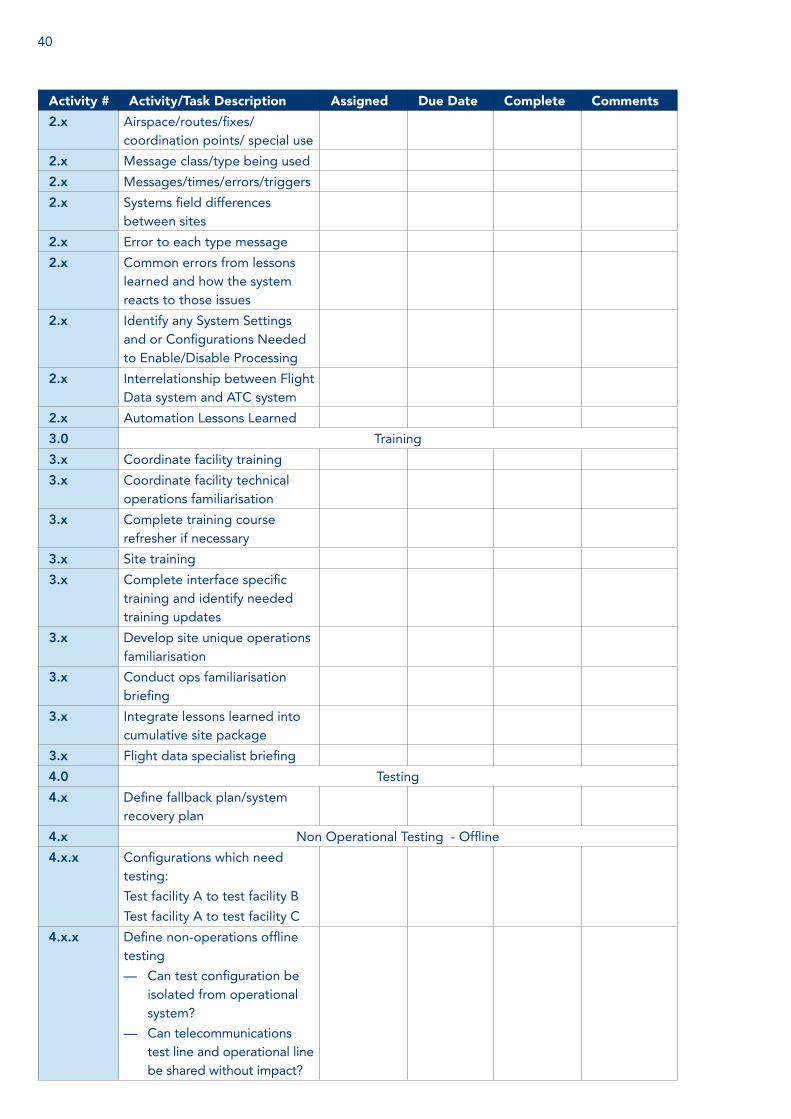
40
Activity # Activity/Task Description Assigned Due Date Complete Comments
2.x Airspace/routes/fixes/ coordination points/ special use
2.x Message class/type being used
2.x Messages/times/errors/triggers
2.x Systems field differences between sites
2.x Error to each type message
2.x Common errors from lessons learned and how the system reacts to those issues
2.x Identify any System Settings and or Configurations Needed to Enable/Disable Processing
2.x Interrelationship between Flight Data system and ATC system
2.x Automation Lessons Learned
3.0 Training
3.x Coordinate facility training
3.x Coordinate facility technical operations familiarisation
3.x Complete training course refresher if necessary
3.x Site training
3.x Complete interface specific training and identify needed training updates
3.x Develop site unique operations familiarisation
3.x Conduct ops familiarisation briefing
3.x Integrate lessons learned into cumulative site package
3.x Flight data specialist briefing
4.0 Testing
4.x Define fallback plan/system recovery plan
4.x Non Operational Testing - Offline
4.x.x Configurations which need testing:
Test facility A to test facility B
Test facility A to test facility C
4.x.x Define non-operations offline testing
— Can test configuration be isolated from operational system?
— Can telecommunications test line and operational line be shared without impact?
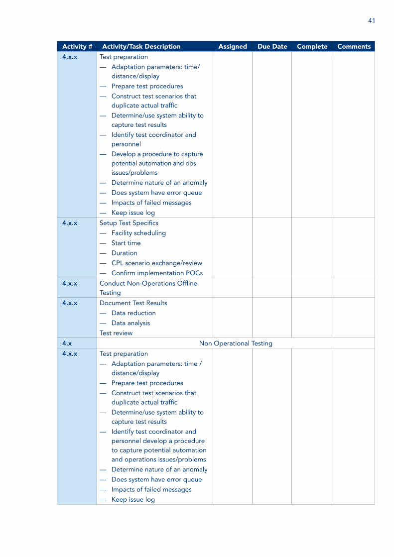
41
Activity # Activity/Task Description Assigned Due Date Complete Comments
4.x.x Test preparation
— Adaptation parameters: time/distance/display
— Prepare test procedures
— Construct test scenarios that duplicate actual traffic
— Determine/use system ability to capture test results
— Identify test coordinator and personnel
— Develop a procedure to capture potential automation and ops issues/problems
— Determine nature of an anomaly
— Does system have error queue
— Impacts of failed messages
— Keep issue log
4.x.x Setup Test Specifics
— Facility scheduling
— Start time
— Duration
— CPL scenario exchange/review
— Confirm implementation POCs
4.x.x Conduct Non-Operations Offline Testing
4.x.x Document Test Results
— Data reduction
— Data analysis
Test review
4.x Non Operational Testing
4.x.x Test preparation
— Adaptation parameters: time /distance/display
— Prepare test procedures
— Construct test scenarios that duplicate actual traffic
— Determine/use system ability to capture test results
— Identify test coordinator and personnel develop a procedure to capture potential automation and operations issues/problems
— Determine nature of an anomaly
— Does system have error queue
— Impacts of failed messages
— Keep issue log

42
Activity # Activity/Task Description Assigned Due Date Complete Comments
4.x.x Setup test specifics
— Facility scheduling
— Start time
— Duration
— CPL scenario exchange/review
Confirm implementation POCs
4.x.x Conduct non-operations testing
4.x.x Document test results
— Data reduction
— Data analysis
Test review
4.x.x Non-operational tests
— Test #1 tested functionality
— Test #2 tested functionality
— Test #3 tested functionality
4.x Operational Live Testing
4.x.x Test preparation
— Tailor operations test plan for facility
— Identify test coordinator and personnel (cadre),
— Coordinate test effort (pre-test meeting)
— Subject matter experts
— Site X
— Site Y
— Tailor test procedure to capture problems and lessons learned
— Complete/review adaptation
— Prepare test procedures
— Develop familiarisation
— Conduct familiarisation
— Review fallback procedures
4.x.x — Setup Test Specifics
— Start time/stop time
— Duration
— Review test procedures
— Verify contacts
— Identify sectors/personnel
— Document Test Results
4.x.x Pre-Test Meeting
Coordinate test
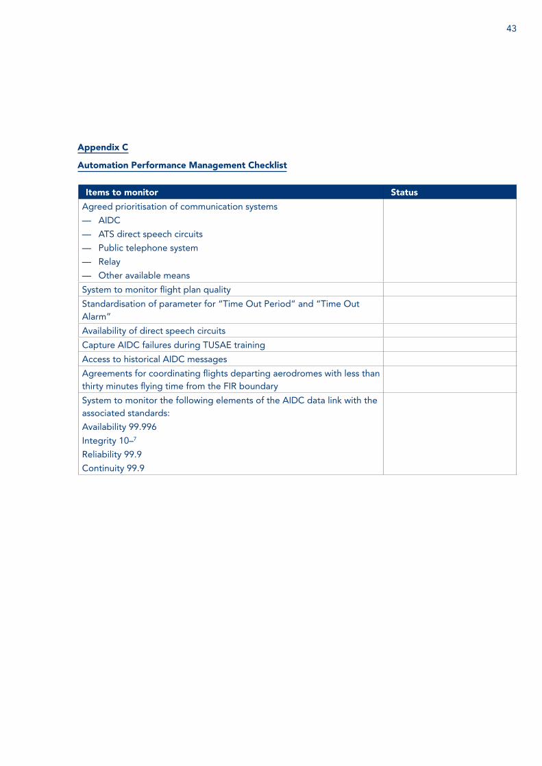
43
Items to monitor Status
Agreed prioritisation of communication systems
— AIDC
— ATS direct speech circuits
— Public telephone system
— Relay
— Other available means
System to monitor flight plan quality
Standardisation of parameter for “Time Out Period” and “Time Out Alarm”
Availability of direct speech circuits
Capture AIDC failures during TUSAE training
Access to historical AIDC messages
Agreements for coordinating flights departing aerodromes with less than thirty minutes flying time from the FIR boundary
System to monitor the following elements of the AIDC data link with the associated standards:
Availability 99.996
Integrity 10–7
Reliability 99.9
Continuity 99.9
Appendix C
Automation Performance Management Checklist
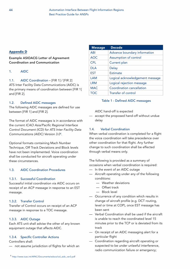
44
Appendix D
Example ASIOACG Letter of Agreement Coordination and Communication
1. AIDC
1.1. AIDC Coordination – [FIR 1] / [FIR 2]ATS Inter Facility Data Communications (AIDC) is the primary means of coordination between [FIR 1] and [FIR 2].
1.2. Defined AIDC messagesThe following AIDC messages are defined for use between [FIR 1] and [FIR 2].
The format of AIDC messages is in accordance with the current ICAO Asia/Pacific Regional Interface Control Document (ICD) for ATS Inter Facility Data Communications (AIDC) Version 3.04.
Optional formats containing Mach Number Technique, Off Track Deviations and Block levels have not been implemented. Voice coordination shall be conducted for aircraft operating under these circumstances.
1.3. AIDC Coordination Procedures
1.3.1. Successful CoordinationSuccessful initial coordination via AIDC occurs on receipt of an ACP message in response to an EST message.
1.3.2. Transfer Control Transfer of Control occurs on receipt of an ACP message in response to a TOC message.
1.3.3. AIDC OutageEach ATS unit shall advise the other of any known equipment outage that affects AIDC.
1.3.4. Specific Controller ActionsControllers shall:
— not assume jurisdiction of flights for which an
Message Decode
ABI Advance boundary information
AOC Assumption of control
CPL Current plan
DLA Delay
EST Estimate
LAM Logical acknowledgement message
LRM Logical rejection message
MAC Coordination cancellation
TOC Transfer of control
AIDC hand-off is expected — accept the proposed hand-off without undue
delay
1.4. Verbal CoordinationWhen verbal coordination is completed for a flight the voice coordination will take precedence over other coordination for that flight. Any further change to such coordination shall be effected through verbal means only.
The following is provided as a summary of occasions when verbal coordination is required:
— In the event of an AIDC outage — Aircraft operating under any of the following
conditions: — Weather deviations — Offset track — Block level
— Occurrence of any condition which results in change of aircraft profile (e.g. DCT routing, level or time at COP), once EST message has been sent
— Verbal Coordination shall be used if the aircraft is unable to reach the coordinated level 15 minutes prior to the TCP or is deviated from its track
— On receipt of an AIDC messaging alert for a particular flight
— Coordination regarding aircraft operating or suspected to be under unlawful interference, radio communication failure or emergency;
Table 1 - Defined AIDC messages
Automation Interface Between Flight Information Regions
Best Practice Guide for ANSPs
4 http://www.icao.int/APAC/Documents/edocs/icd_aidc_ver3.pdf
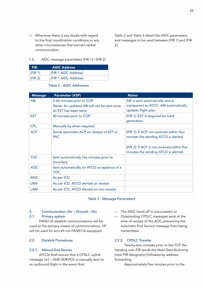
45
— Whenever there is any doubt with regard to the final coordination conditions or any other circumstances that warrant verbal communication.
1.5. AIDC message parameters [FIR 1] / [FIR 2]
FIR AIDC Address
[FIR 1] [FIR 1 AIDC Address]
[FIR 2] [FIR 1 AIDC Address]
Table 2 - AIDC Addresses
Message Parameter (VSP) Notes
ABI 5-60 minutes prior to COP
(Note: An updated ABI will not be sent once an EST has been sent)
ABI is sent automatically and is transparent to ATCO. ABI automatically updates flight plan.
EST 40 minutes prior to COP [FIR 1]: EST is required for track generation.
CPL Manually by when required
ACP Sends automatic ACP on receipt of EST or PAC
[FIR 1]: If ACP not received within four minutes the sending ATCO is alerted.
[FIR 2]: If ACP is not received within five minutes the sending ATCO is alerted.
TOC Sent automatically five minutes prior to boundary
AOC Sent automatically on ATCO acceptance of a TOC
MAC As per ICD
LRM As per ICD. ATCO alerted on receipt
LAM As per ICD. ATCO alerted on non-receipt
Table 3 - Message Parameters
2. Communication (Air – Ground – Air)2.1. Primary system
FANS1/A datalink communications will be used as the primary means of communications. HF will be used for aircraft not FANS1/A equipped.
2.2. Datalink Procedures
2.2.1. Manual End ServiceATCOs shall ensure that a CPDLC uplink
message 161 – END SERVICE is manually sent to an outbound flight in the event that:
— The AIDC hand-off is unsuccessful or — Outstanding CPDLC messages exist at the
time of receipt of the AOC preventing the automatic End Service message from being transmitted.
2.2.2. CPDLC TransferTwenty-two minutes prior to the TCP the
handing over FIR sends the Next Data Authority [next FIR designator] followed by address forwarding.
Approximately five minutes prior to the
Table 2 and Table 3 detail the AIDC parameters and messages to be used between [FIR 1] and [FIR 2].

46
boundary the handing over FIR shall instruct the aircraft via CPDLC to MONITOR [“next FIR”] [frequency].
Upon receipt of downlink response, the handing over FIR shall send uplink message 161 – END SERVICE.
If the address forwarding is unsuccessful the handing over FIR shall follow the procedures outlined below:
— Approximately five minutes prior to the TCP the handing over FIR will instruct the aircraft via CPDLC to:
— Manually disconnect from [FIR 1 code] then Logon to [FIR 2 code]
— MONITOR [“next FIR”] [frequency]
2.3. Address forwarding and next data authority
[FIR 1] / [FIR 2] shall send automatic Next Data Authority (NDA) and Address Forwarding (CAD) for data link aircraft as per Table 4 - Datalink Parameters.
2.4. Responsibility for SAR alerting servicesIrrespective of the aircraft’s position with
regard to the FIR boundary, the CDA (Current Data Authority) will be responsible for SAR alerting services with respect to that particular flight.
FIR Next Data Authority (NDA) and Address Forwarding (CAD)
[FIR 1] Auto NDA sent 22 minutes prior to the FIR boundary
Auto CAD sent 20 minutes prior to the FIR boundary
[FIR 2] Auto NDA sent 22 minutes prior to the FIR boundary
Auto CAD sent 20 minutes prior to the FIR boundary
Table 4 - Datalink Parameters
Automation Interface Between Flight Information Regions
Best Practice Guide for ANSPs

47
Appendix E:
Example of an Addendum to Existing LOA
Automated Data Exchange (ADE)1. PURPOSE: Establishes procedures for the automated data exchange of active flight plan information between Miami Center (KZMA) and Havana Center (MUFH). Subsequent sub-sections will introduce abbreviations, definitions and operational procedures to be used by respective facilities.
2. OPERATIONAL PROCEDURES FOR ADE IS DESCRIBED IN THIS SECTION. These procedures will evolve as subsequent phases are introduced. This Attachment may be deleted and absorbed into the main body of the Letter of Agreement when the final phase is implemented and with mutual agreement.
3. ABBREVIATIONS:ADE: Automated data exchangeCFL: Coordinated flight levelCPL: Active flight planFPL: Proposed flight planLAM: Logical acknowledgement messageUTM: Unsuccessful transmission messageLRM: Logical reject message
4. PROCEDURES:4.1. ADE is the primary method of
exchanging flight data information between KZMA and MUFH.
4.2. Coordination.4.2.1. The parameter times for the
interface are as follows:a. Not less than 15 minutes - MUFH CPL
send time (prior to boundary).b. 60 seconds - MUFH LAM time-out (time
to wait for LAM from KZMA).c. Not less than 13 minutes - KZMA CPL
send time (prior to boundary)d. 60 seconds - KZMA LAM time-out (time
to wait for LAM from MUFH).
e. KZMA and MUFH may agree to modify the parameters listed in a) and c) as necessary to enhance the automation system.
4.2.2. The transferring facility must ensure that CPLs are verified with the receiving facility for all UTMs.
4.2.3. MUFH will indicate “NO FPL IN MUFH” in the remarks field of the CPL when a FPL is not received by MUFH.
5. FLIGHT LEVEL COORDINATION5.1. Aircraft will be assigned flight
levels in accordance with paragraph 6.2 in this Letter of Agreement without CFL update.
5.1.1. All Miami Terminal arrivals over TADPO must be at FL360 or below.
5.1.2. Departures overflying TANIA must be at FL280 or below.
6. SCHEDULED AND NON-SCHEDULED OUTAGES
6.1. When ADE is disabled the primary method of exchanging FPL messages will be the MEVA dial line in accordance with paragraph 12.2.
6.2. The MUFH and KZMA operational managers must mutually agree when to effect and or re-establish a transition to/from the MEVA dial line and ADE.
6.3. KZMA and MUFH will coordinate, in advance or as soon as practical, all scheduled and non-scheduled outages which impact ADE.

48
Appendix F
Addendum to Existing LOA between ATSU1 and ATSU2 ACCS
The implementation of AIDC between ATSU1 and ATSU2 ACCs has been finalized. The existing Letter of Agreement between these two ACCs requires to be amended. Following addendum to the existing Letter of Agreement between ATSU1 and ATSU2 has been drafted for approval.
1. Exchange of estimates(Paragraph XX may be replaced /
renumbered as below)1.1. Estimates/Coordination Messages
(Revisions) in case of AIDC
The AIDC procedures for movement and control of ATS messages shall apply as follow:
1.1.1. The format of AIDC messages are as defined by the Asia/Pacific Regional AIDC Interface Control Document (ICD) Version 2 and as amended from time to time, unless described otherwise in this LOA.
1.1.2. A successful coordination via AIDC will be assumed to occur on receipt of an ACP message in response to CDN after EST message.
1.1.3. Voice coordination is not required when AIDC messaging has been successful.
1.1.4. Due any reason for a particular flight or for other reasons as whole, if AIDC messaging is not to be carried out and voice coordination has been accomplished.
1.1.5. Different occasions/matters which are not included in the current version of AIDC messaging but requiring voice coordination is given in paragraph XXXX.
1.1.6. Acceptance of a CDN message is
approval of the flight’s profile and requires no voice coordination.
1.1.7. If there is any doubt with final coordination data, voice coordination shall be used for confirmation.
1.1.8. Receipt of a MAC message shall not be interpreted as cancellation of flight plan as it indicates that all previous notifications and coordination are no longer relevant to receiving unit for that flight. Voice coordination must be conducted by the transferring unit to confirm the status of the flight.
1.1.9. Each facility shall advise the other facility of any known equipment outage that affects AIDC. In the event of AIDC outage, voice coordination procedures will apply.
1.1.10. Transfer of control points (TCPs) will be same as defined in para XXX of the existing LOA. Units shall send any revised estimates through AIDC that vary by 3 minutes or more.
1.1.11. Means of communication for coordination between adjacent units shall be in the following order of priority:
a. AIDC Messages (with mutual coordination)
b. ATS direct speech circuitsc. Telephone System
1.1.12. Voice communication on existing hot lines will be carried out as given below:
d. In the event of an AIDC outage, or;e. Aircraft operating in any of the following
conditions:1. Block level clearance2. Time constraints3. Weather deviations4. Off track due traffic5. Application of Mach number
technique
Automation Interface Between Flight Information Regions
Best Practice Guide for ANSPs

49
6. When an ACP has not received7. On receipt of a MAC message8. In case of any doubt regarding final
coordination9. In case of emergency to an aircraft10. To resolve queries regarding civil or
1.1.13. AIDC MEASSAGES PARAMETERS:
Messages Parameter Notes
ABI ATSU1: Sends ABI 60 minutes prior to boundary.
ATSU2: Sends ABI 50 minutes prior to boundary on routes
AXXX / BXXX and 40 minutes on CXXX
ATSU1 and ATSU2: ABI is sent automatically and is
transparent to the ATCO. Updated ABI’s will be sent
automatically if there is any change to profile. ABI
automatically updates the receiving unit’s flight data
record.
EST ATSU1: Sends EST messages 30 minutes prior to boundary.
ATSU2: Sends EST messages 45 minutes prior to boundary
on routes AXXX / BXXX and 30 minutes on CXXX
ATSU1 and ATSU2: EST is sent automatically and
updates the receiving unit. EST messages changed the
profile “CORG”.
CDN ATSU1 and ATSU2: CDN messages are sent by either the
transferring or receiving facility to propose a change once
the coordination process has been completed, i.e., EST sent
and ACP received. CDNs must contain all applicable profile
restrictions e.g. waypoint, estimate and level. The use of
CDN does not support profiles on weather deviations,
speed assignment, block altitudes etc., to which verbal
coordination is required.
ATSU1 and ATSU2: If the ATSU1 ACC does not like the
current clearance and (boundary crossing conditions), in
negotiation process is carried out using CDN.
PAC ATSU1 and ATSU2: PAC messages will normally be sent
when the time criteria from the departure point to the
boundary is less than that stipulated in the FPL.
ATSU1 and ATSU2: Will respond to a PAC message with
an REJ/ACP. PAC messages shall be verbally verified
with receiving facility.
ACP ATSU1 and ATSU2: ACP messages are in reply to an EST/
CDN message if conditions specified in EST/CDN are
acceptable to ATCO.
ATSU1 and ATSU2: The negotiation process is
terminated when the accepting ATSU signals its
acceptance of the coordination condition using an
ACP message. If the ACP is not received within three
minutes, the ATCO should repeat the process once
again.
TOC ATSU1 and ATSU2: Transfer of Control ATSU1 and ATSU2: A TOC is sent after coordination
occurs but before the boundary is crossed to the
accepting ATSU. The TOC informs the accepting ATSU
that it now has controlled authority of the aircraft.
AOC ATSU1 and ATSU2: Assumption of Control ATSU1 and ATSU2: The accepting ATSU is now the
controlling ATSU
MAC ATSU1 and ATSU2: MAC messages are sent when a change
to the route makes the other facility no longer the “next”
responsible unit.
ATSU1 and ATSU2: Receipt of a MAC message must not
be interpreted as meaning that the flight plan has been
cancelled. Voice coordination must be conducted by
the transferring ATCO to confirm the status of the flight.
REJ ATSU1 and ATSU2: REJ messages are sent in reply to a CDN
message when the requested change is unacceptable.
ATSU1 and ATSU2: REJ messages are sent only as a
response to a CDN message.
military clearance11. To pass information of VVIP
movements.12. For coordination while releasing
traffic in climbing or descending phase

50
NOTE: In case of outage/failure of AIDC contingency procedures as given in paragraph 1.3.2 and 1.3.3, the measures in paragraphs 6.3 and 6.4 will be implemented:
1.2. Estimates/Coordination messages (Revisions) in case of AIDC Failure
1.2.1. The estimate message (EST) shall be transmitted in sufficient time to permit receipt by the relevant ACC normally no later than 30 minutes prior to the time the flight is estimated to pass over the transfer of control point. The EST message shall contain information in the format mentioned in paragraph 21.3.3
1.2.2. Revision to the estimate at the transfer of control point shall be passed to the receiving ATC unit if the revised estimate time different by three minutes or more.
1.2.3. In the event that communication with the aircraft is not established with five minutes after the estimated time over the transfer of control point, the receiving ATC unit shall notify the transferring ATC unit of this fact.
1.3. Message Contents1.3.1. Coordination messages exchange
between the ATS units shall contain the following data in the order listed:
a. Aircraft identification including SSR code.
b. Type of aircraft.c. Departure aerodrome.d. Estimated time/level over the transfer of
control point.e. True air speed/Mach number assigned if
any restriction apply.f. Destination aerodromeg. RVSM statush. Any other information as required.
6.3. Estimates6.3.1. The primary means of exchanging
estimates are through AIDC as mentioned in paragraph 1.1. In case of AIDC failure, the procedure given in paragraph 1.2.1 will be implemented.
6.3.2. Estimates (EST) messages shall be sent, using the appropriate “Voice circuit: (Land Line or HF Radio), for all flights crossing the transfer of control point in sufficient time to permit receipt by the accepting ATC unit not less than 30 minutes but not earlier than one hour before the estimated time for the aircraft to be over the transfer of control point. The message shall be transmitted to aircraft in accordance with the phraseology specified in Doc.4444 ATM/507 chapter 12 paragraph 3.5.
6.3.3. Estimates messages shall include the transponder code assigned by the transferring ACC.
6.3.4. If the point of departure of an aircraft is not at a sufficient distance from the common FIR boundary to permit transmission of the estimate 30 minutes before the aircraft estimates TCP, the transferring unit shall forward the flight data to be accepting unit prior to departure of aircraft.
6.4. Revisions6.4.1. The primary means of exchange
of revision are through AIDC as mentioned in paragraph 1.1.
6.4.2. Whenever there will be a variation of three minutes or more from the estimated time that was originally passed or when a change of the cleared level and/or crossing condition is planned “Revision and other “Coordination: (CDN) messages shall normally be sent using the appropriate “Voice Circuit” (land Line or HF radio), as soon as practicable.
6.4.3. The transferring ATS unit shall send
Automation Interface Between Flight Information Regions
Best Practice Guide for ANSPs

51
“Revision” and other “coordination” messages to the accepting ATS units at least 20 minutes prior to the aircraft estimated time over the transfer of control point.
6.4.4. In case of non-availability of the ATS “Voice Circuit” between the ATS units concerned the transferring ATS units shall send the relevant data to the accepting ATS unit via the AFTN.
6.4.5. “Estimates”, “Revisions” and other “coordination” messages when sent the AFTN require an “acknowledgment” from the acceptance ATS units in the form of an “acceptance” (ACP) message, to be sent to the transferring ATS units
6.4.6. After coordination of the transfer of control conditions, the resulting ATC Clearance shall not be changed by the transferring ATS unit unless prior agreement has been affected between the ATS units concerned.
6.4.7. The use of communication system for coordination between adjacent ATS units shall be the following order of priority:
— Direct speech circuit — IDD Telephone — AFTN
6.4.8. In case of flights departing from aerodromes where, due to their proximity to the transfer control point [refer sub section 2.2.1 Note b] application of the procedures set out in paragraph 6.4.6 above would not be possible after departure, coordination between the transfer of ATS units and the accepting ATS units shall be effected prior to the issuance of accepting clearance to the aircraft concerned. (See ICAO DOC 4444, ATM/501 chapter 10 paragraph 10.4.2.1)
6.4.9. In case of primary circuit failure, each unit shall endeavour to utilise any other
available means of communication including ISD telephone
6.4.10. Provided that continuous voice communication is available, the transmission DEP/EST/CHG messages by AFTN shall not be required.
10. Authorised Signature

4D Four dimensional
AAI Airports Authority of India
ABI Advance boundary information (message)
ACC Area control centre
ACI Airports Council International
ACP Acceptance (message)
ADE Automated data exchange
ADS-B Automatic dependent surveillance-broadcast
ADS-C Automatic dependent surveillance-contract
AFN Air traffic services facilities notification
AFTN Aeronautical fixed telecommunication network
AIDC ATS inter-facility data communication
AIP Aeronautical information publication
AIRAC Aeronautical information regulation and control
AMHS Automatic message handling system
ANSP Air navigation service provider
AOC Acceptance of control (message)
APAC Asia and Pacific
ARTCC Air Route Traffic Control Center
ASBU Aviation System Block Upgrades
ATC Air traffic control
ATCO Air traffic control officer
ATFM Air traffic flow management
ATM Air traffic management
ATN B1 Aeronautical Telecommunication Network Baseline 1 (data link) applications)
ATOP Advanced Technologies and Oceanic Procedures (system)
ATS Air traffic service
ATSU Air traffic service unit
B0 Block 0 (up to 2018)
B1 Block 1 (2018 to2023)
B2 Block 2 (2023 to 2028)
B3 Block 3 (2028 and onwards)
CAATS Canadian Automated Air Traffic System
CANSO Civil Air Navigation Services Organisation
CCO Continuous climb operations
CDA Current data authority
CDN Coordination (message)
CDO Continuous descent operations
CNS Communication, navigation and surveillance
COCESNA Corporación Centroamericana de Servicios de Navegación Aérea
COP Coordination point
CPDLC Controller-pilot data link communication
Acronyms
Automation Interface Between Flight Information Regions
Best Practice Guide for ANSPs
52

CPL Current flight plan
CR1 Connection request (message)
CRC Cyclic redundancy check
CZVR Vancouver ACC
DARP Dynamic airborne reroute procedure
EST Estimate (message)
EUR European
FAA United States Federal Aviation Administration
FAN Future air navigation system application notification (message)
FANS 1/A Future Air Navigation System (data link applications)
FCN Future air navigation system completion notification (message)
FDPS Flight data processing system
FF-ICE (FICE) Flight and Flow Information for a Collaborative Environment
FIR Flight information region
FIRBX CANSO FIR Boundary Crossings Task Force
FN_CAD Air traffic services facilities notification contact advisory (message)
FPL Filed flight plan
GANP Global Air Navigation Plan (ICAO Doc 9750)
GASP ICAO Global Aviation Safety Plan 2014-2016
GOLD Global Operational Data Link Document
HMI Human-machine interface
IATA International Air Transport Association
ICAO International Civil Aviation Organization
ICD Interface control document
IFATCA International Federation of Air Traffic Controllers’ Associations
IFPS Initial flight plan processing system
IP Internet Protocol
KZMA Miami Air Route Traffic Control Center
KZNY New York Air Route Traffic Control Center
KZOA Oakland Air Route Traffic Control Center
LAM Logical acknowledgment message
LOA Letter of agreement
LRM Logical rejection message
MAC Coordination cancellation (message)
METAR Meteorological aviation report
MID Middle East
MUFH Havana area control centre
NACC North American, Central American and Caribbean
NAM North American
NAM ICD North American Interface Control Document
NAT North Atlantic
NDA Next data authority
NOPS Network operations
53

NOTAM Notice to Airmen
ODF Optional data field
OLDI Online data interchange
PAC Pre-activation (message)
PAN AIDC ICE Pan Regional (NAT and APAC) Interface Control Document for ATS
PANS ATM Procedures for Air Navigation Services - Air Traffic Management
PBN Performance-based navigation
PIA Performance improvement area
REJ Rejection (message)
SAM South American
SESAR Single European Sky ATM Research
SID Standard instrument departure
SIGMET Significant Meteorological Information
SMM Safety Management Manual (ICAO Doc 9859)
SMS Safety management system
SSR Secondary surveillance radar
STAR Standard instrument arrival
SWIM System-wide Information Management
TAF Terminal aerodrome forecast
TBO Trajectory-based operations
TCP Transfer of control point
TDM Track definition message
TOC Transfer of control (message)
U.S. United States
UPR User preferred route
VHF Very high frequency
VOR VHF omni-directional radio range
VSP Variable system parameter
ZAK Oakland ATOP sector
Automation Interface Between Flight Information Regions
Best Practice Guide for ANSPs
54


Full Members - 87 — Aeronautical Radio of Thailand (AEROTHAI) — Aeroportos de Moçambique — Air Navigation and Weather Services,
CAA (ANWS) — Air Navigation Services of the Czech Republic
(ANS Czech Republic) — AirNav Indonesia — Air Traffic & Navigation Services (ATNS) — Airports and Aviation Services Limited (AASL) — Airports Authority of India (AAI) — Airports Fiji Limited — Airservices Australia — Airways New Zealand — Albcontrol — Austro Control — Avinor AS — AZANS Azerbaijan — Belgocontrol — Bulgarian Air Traffic Services Authority
(BULATSA) — CAA Uganda — Cambodia Air Traffic Services Co., Ltd. (CATS) — Civil Aviation Authority of Bangladesh (CAAB) — Civil Aviation Authority of Botswana — Civil Aviation Authority of Mongolia — Civil Aviation Authority of Nepal (CAAN) — Civil Aviation Authority of Singapore (CAAS) — Civil Aviation Authority of the Philippines — Civil Aviation Regulatory Commission (CARC) — COCESNA — Croatia Control Ltd — DCA Myanmar — Department of Airspace Control (DECEA) — Department of Civil Aviation, Republic of Cyprus — DFS Deutsche Flugsicherung GmbH (DFS) — Dirección General de Control de Tránsito Aéreo
(DGCTA) — DSNA France — Dubai Air Navigation Services (DANS) — Dutch Caribbean Air Navigation Service Provider
(DC-ANSP) — ENAV S.p.A: Società Nazionale per l’Assistenza
al Volo — ENAIRE — Estonian Air Navigation Services (EANS) — Federal Aviation Administration (FAA) — Finavia Corporation — General Authority of Civil Aviation (GACA) — Ghana Civil Aviation Authority (GCAA) — HungaroControl Pte. Ltd. Co. — Instituto Dominicano de Aviacion Civil (IDAC) — Israel Airports Authority (IAA) — Irish Aviation Authority (IAA) — ISAVIA Ltd — Japan Air Navigation Service (JANS) — Kazaeronavigatsia — Kenya Civil Aviation Authority (KCAA) — Latvijas Gaisa Satiksme (LGS)
CANSO Members
Membership list correct as of 6 June 2016. For the most up-to-date list and organisation profiles go to canso.org/canso-members
— Letové prevádzkové Služby Slovenskej Republiky, Štátny Podnik
— Luchtverkeersleiding Nederland (LVNL) — Luxembourg ANA — Maldives Airports Company Limited (MACL) — Malta Air Traffic Services (MATS) — National Airports Corporation Ltd. — National Air Navigation Services Company
(NANSC) — NATS UK — NAV CANADA — NAV Portugal — Naviair — Nigerian Airspace Management Agency (NAMA) — Office National de LÁviation Civile (OFNAC) — Office National Des Aéroports (ONDA) — ORO NAVIGACIJA, Lithuania — PIA “Adem Jashari” - Air Control J.S.C. — PNG Air Services Limited (PNGASL) — Polish Air Navigation Services Agency (PANSA) — Public Authority for Civil Aviation - Oman (PACA) — ROMATSA — Sakaeronavigatsia Ltd — SENEAM — Serbia and Montenegro Air Traffic Services
Agency (SMATSA) — Serco — skyguide — Slovenia Control — State Airports Authority & ANSP (DHMI) — Sudan Air Navigation Services Department — Swaziland Civil Aviation Authority — Tanzania Civil Aviation Authority — Trinidad and Tobago CAA — The LFV Group — Ukrainian Air Traffic Service Enterprise (UkSATSE) — U.S. DoD Policy Board on Federal Aviation — Viet Nam Air Traffic Management Corporation
(VATM)
Gold Associate Members - 11 — Airbus ProSky — Anhui Sun Create Electronics Co., Ltd. — Boeing — FREQUENTIS AG — GroupEAD Europe S.L. — Harris Corporation — Inmarsat Plc — Lockheed Martin — Raytheon — Finmeccanica — Thales
Silver Associate Members - 66 — 42 Solutions B.V. — Adacel Inc. — Aeronav Inc. — Aireon
— Air Traffic Control Association (ATCA) — ALES a.s. — Association Group of Industrial Companies
“TIRA” Corporation — ATAC — ATCA – Japan — ATECH Negócios em Tecnologia S/A — Aveillant — Aviation Advocacy Sarl — Aviation Data Communication Corp (ADCC) — Avibit Data Processing GmbH — Avitech GmbH — Bayanat Engineering Group — Brüel & Kjaer EMS — CGH Technologies, Inc. — Comsoft GmbH — CSSI, Inc. — Airbus Defence and Space — EIZO Technologies GmbH — European Satellite Services Provider (ESSP SAS) — Emirates — ENAC — Entry Point North — Era Corporation — Esterline — Etihad Airways — Guntermann & Drunck GmbH — Helios — Honeywell International Inc. / Aerospace — IDS – Ingegneria Dei Sistemi S.p.A. — Indra Navia AS — Indra Sistemas — INECO — Integra A/S — Intelcan Technosystems Inc. — International Aero Navigation Systems Concern,
JSC — Jeppesen — JMA Solutions — Jotron AS — Kongsberg Defence & Aerospace AS — LAIC Aktiengesellschaft — LEMZ R&P Corporation — Lufthansa Systems FlightNav AG — MDA Systems Ltd. — Metron Aviation — Micro Nav Ltd — The MITRE Corporation – CAASD — MovingDot — NEC Corporation — NLR — Northrop Grumman — NTT Data Corporation — Rockwell Collins, Inc. — Rohde & Schwarz GmbH & Co. KG — Saab AB — Saab Sensis Corporation — Saudi Arabian Airlines — SENASA — SITA — Snowflake Software Ltd — STR-SpeechTech Ltd. — Tetra Tech AMT — Think Research Limited
CANSO – the Civil Air Navigation Services Organisation – is the global voice of air traffic management (ATM) worldwide. CANSO Members support over 85% of world air traffic. Members share information and develop new policies, with the ultimate aim of improving air navigation services (ANS) on the ground and in the air.
CANSO represents its Members’ views to a wide range of aviation stakeholders, including the International Civil Aviation Organization, where it has official Observer status. CANSO has an extensive network of Associate Members drawn from across the aviation industry. For more information on joining CANSO, visit canso.org/join-canso civil air navigation services organisation