automobile engineering engineering ppt 9jan2020.pdfengine parts and operation • most autos use a...
TRANSCRIPT

AUTOMOBILE ENGINEERINGCourse code:AME020
IV. B.Tech II semesterRegulation: IARE R-16
BY Mr. VKVS Krishnam Raju
Assistant ProfessorMr. Prashanth Reddy
DEPARTMENT OF MECHANICAL ENGINEERINGINSTITUTE OF AERONAUTICAL ENGINEERING
(Autonomous)DUNDIGAL, HYDERABAD - 500 043
1

2
COs Course Outcome
CO1 Understanding Automobile engines, fuel supply system,injection components.
CO2 Understanding of ignition systems, cooling processesand Electrical system.
CO3 Understanding the working of transmission andsuspension systems of various automobiles.
CO4 Understanding the working of braking and steeringsystems of various automobiles.
CO5 Understanding the national pollution standards andincorporating emission control techniques. Usage ofalternating fuels.

UNIT–IINTRODUCTION TO AUTOMOBILE ENGINEERING
3
4
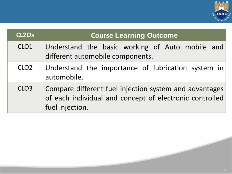
CL2Os Course Learning Outcome
CLO1 Understand the basic working of Auto mobile anddifferent automobile components.
CLO2 Understand the importance of lubrication system inautomobile.
CLO3 Compare different fuel injection system and advantagesof each individual and concept of electronic controlledfuel injection.

• Describe the differences between the unibody design and
frame and body design
• Tell how the four-stroke cycle engine operates
• Understand the purposes of the major engine support
systems
• Describe the parts of front- and rear-wheel drive
powertrains
• Explain major events in the history of the automobile

• Automobiles have around more than 100 years
– Originally called horseless carriages
• Today more than 130 million cars in the U.S.
– One-third of cars in the world
• Source of employment for one in nine workers
• Americans drive 7,767 miles per year
• Automobiles include several systems
– Body and suspension, engine, electrical, etc.
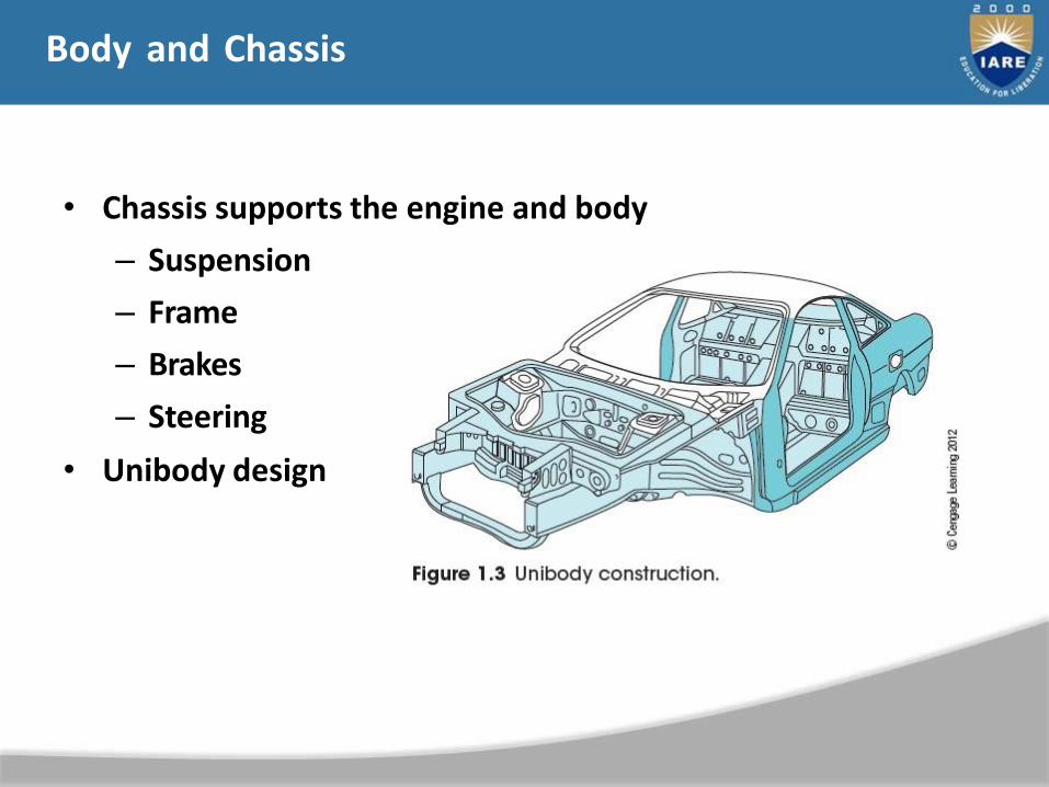
Body and Chassis
• Chassis supports the engine and body
– Suspension
– Frame
– Brakes
– Steering
• Unibody design
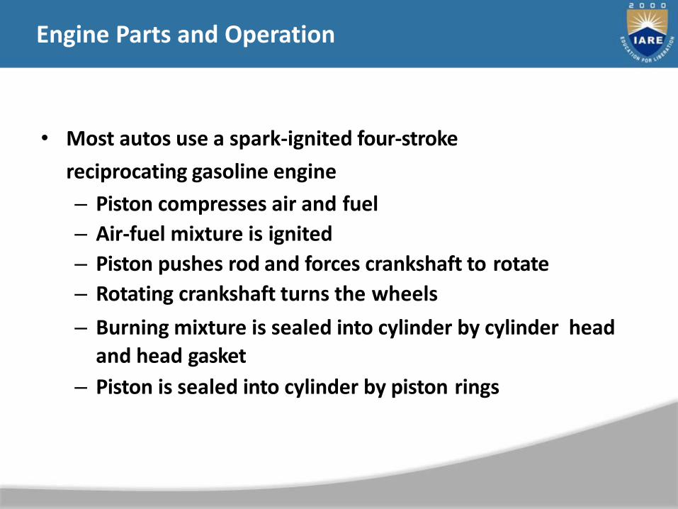
Engine Parts and Operation
• Most autos use a spark-ignited four-stroke
reciprocating gasoline engine
– Piston compresses air and fuel
– Air-fuel mixture is ignited
– Piston pushes rod and forces crankshaft to rotate
– Rotating crankshaft turns the wheels
– Burning mixture is sealed into cylinder by cylinder head and head gasket
– Piston is sealed into cylinder by piston rings

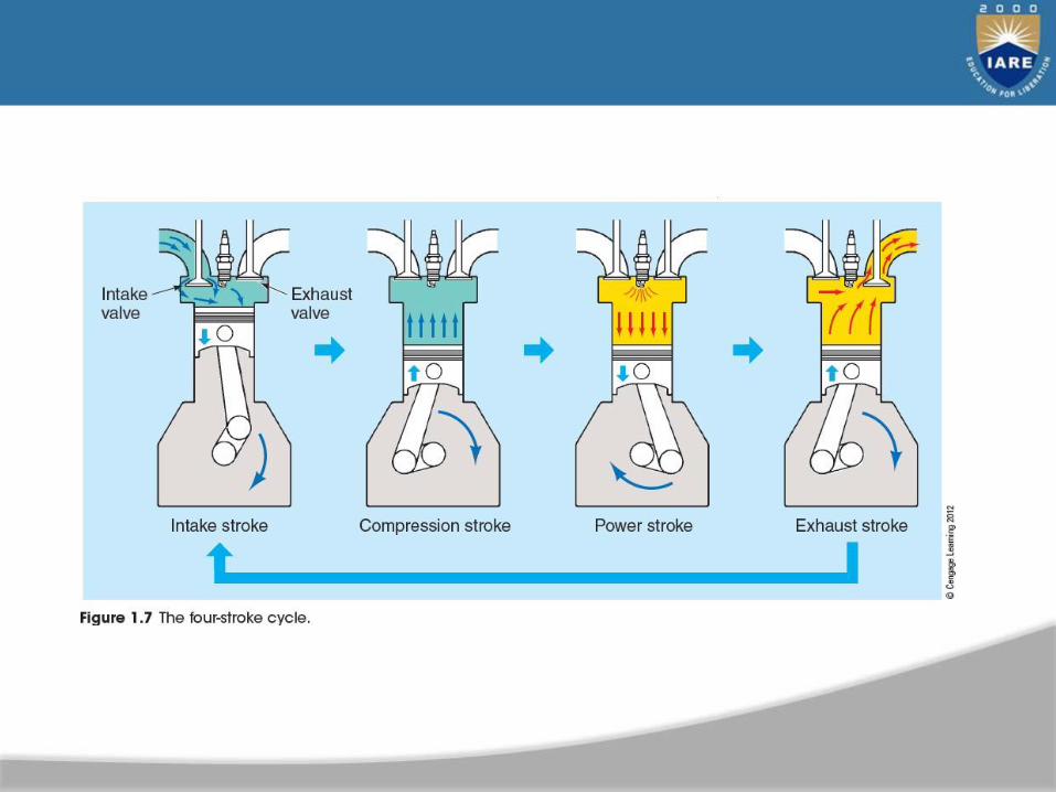
• Four-stroke cycle
– Intake stroke
• Piston is pulled down by crankshaft
– Compression stroke
• Both valves close and piston moves up
– Power stroke
• Burning fuel expands and forces pistondown
– Exhaust stroke
• Piston moves up and forces exhaust out
Engine Parts and Operation
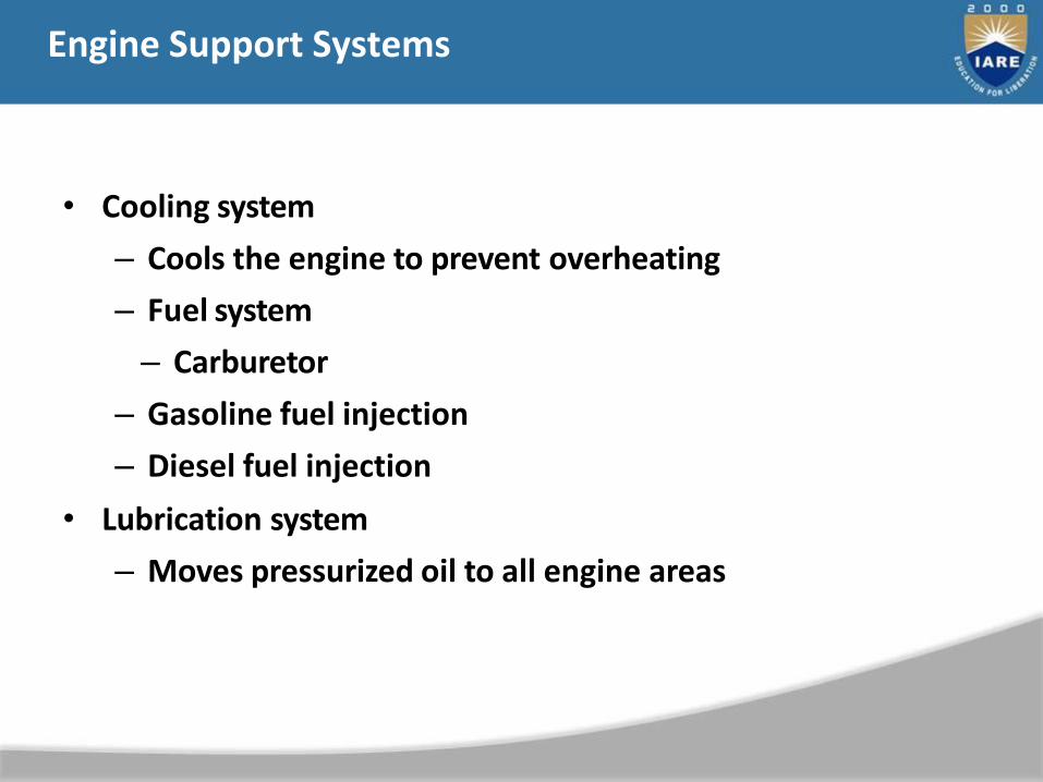
Engine Support Systems
• Cooling system
– Cools the engine to prevent overheating
– Fuel system
– Carburetor
– Gasoline fuel injection
– Diesel fuel injection
• Lubrication system
– Moves pressurized oil to all engine areas
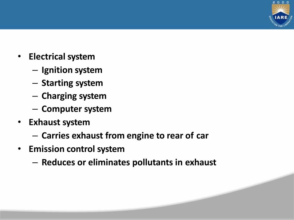
• Electrical system
– Ignition system
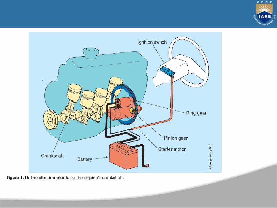
– Starting system
– Charging system
– Computer system
• Exhaust system
– Carries exhaust from engine to rear of car
• Emission control system
– Reduces or eliminates pollutants in exhaust

The Powertrain
• Transmits engine power to wheels
– Transmission (transaxle)
– Clutch
– Torque converter
– Differential
– Axles or half-shafts
• Front-wheel drive, rear-wheel drive, or all- wheel drive
• Manual or automatic

• Manual transmission
– Gears change leverage or torque
– Clutch uncouples powertrain from engine
• Automatic transmission
– Gears shifted based on speed and engine load
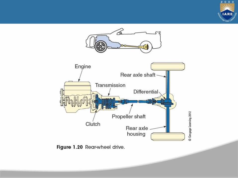
• Drive shaft
– Used on rear-wheel drive cars to transfer power to the rear axle
– Hollow metal tube with universal joint at each end
• Rear axle assembly
– Drive axles power each rear wheel and a differential assembly
• Transaxle
– Used on front-wheel drive vehicles
– Transmission and differential in one housing

Accessory Systems
• Also called comfort systems
– Air conditioning
– Heating
– Power seats
– Power windows
– Cruise control
– Navigation, sound systems, etc.
History and Development of the Automobile
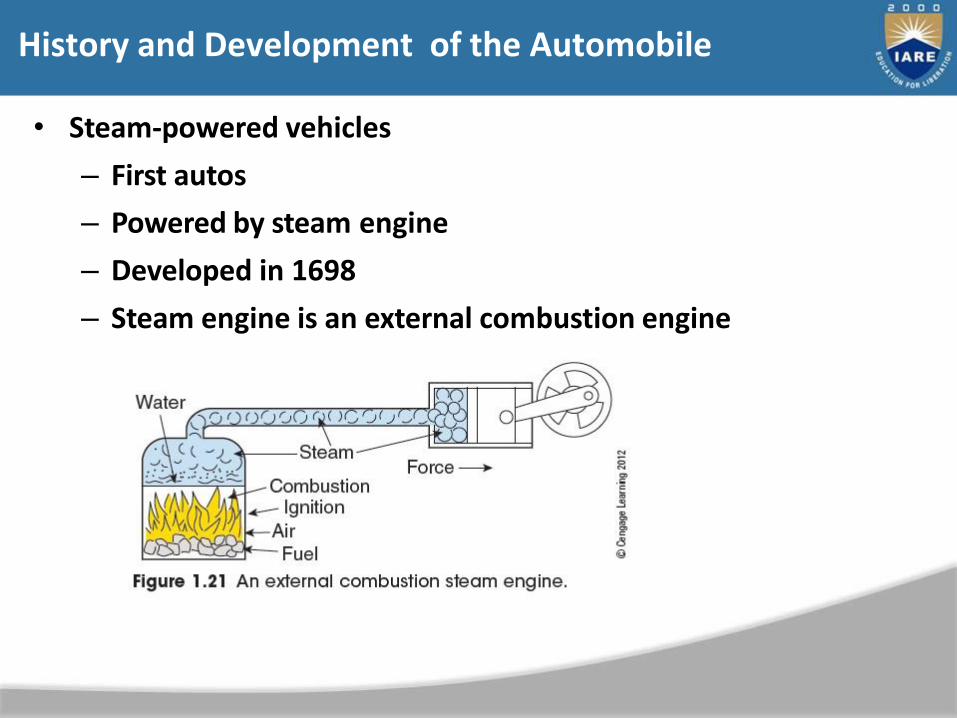
• Steam-powered vehicles
– First autos
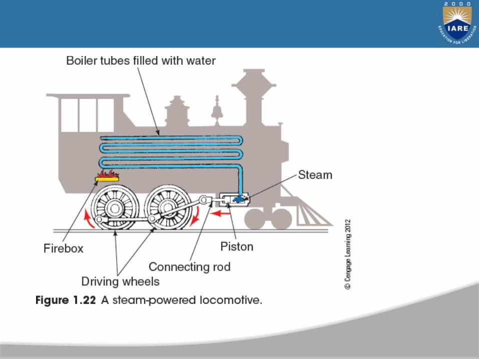
– Powered by steam engine
– Developed in 1698
– Steam engine is an external combustion engine
• Early gasoline engines
– 1876: Dr. Nicolas Otto patented the slow-speed, four-stroke, internal combustion engine
– 1885: Gottlieb Daimler patented high-speed, petroleum engine
– 1893: Benz shown at the World’s Fair in Chicago
– 1920: 90% of cars looked like carriages
– 3.8 million miles of road in the U.S. has been developed in less than 100 years
• Early automobile racing
– 1895: First auto race in Chicago
– 1913: Indianapolis 500 started
• Early transmissions
– Early cars had transmission on rear axle
• Later attached to rear of engine
• Carburetors
– Early carburetors had a wick saturated with gasoline
• Later had a bowl full of gasoline

• Fuel pumps
– 1915: Stewart Warner vacuum tank
– 1928: Electric and mechanical fuel pumps
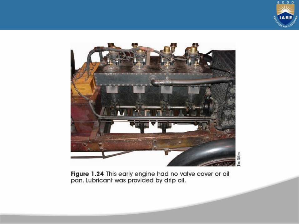
• Lubrication systems
– Early engines used a drip oiler
• Later cars had mechanical oiling
• Tires
– 1900: Michelin’s first pneumatic tires
– 1919: All cars are equipped with cord tires

• Electrical systems
– Early cars had 8-, 12-, or 24-volt systems
– 1915: 6-volt battery became standard
– 1950s: 12-volt batteries became standard
• Starter system
– Early engines hand cranked to start
– 1912: Kettering electric starter motor
• Early American automobiles
– 1892: Charles and Frank Duryea build first
operational car
– 1908-1926: Henry Ford produced the Model T
• Assembly line produced 1000 per day
– General Motors: Durant wanted to produce a variety of cars
• Good promoter, but poor business man
• Removed from GM
– 1919: Walter Chrysler starts Chrysler Corporation
• Later developments
– 1950s: American cars became large and powerful
• Poor fuel economy and high pollution
• Fuel economy standards
– 1973: Gas prices quadrupled
– 1975: U.S. Congress passed CAFE
• Modern developments
– Today’s cars benefit from military and space program innovations
– Advancements have improved safety and reliability
Engine Classifications and Advanced Transportation Technologies
Objectives
• Explain various engine classifications and systems
• Know the various differences in cylinder heads
• Describe differences in operation between gasoline and diesel four-stroke piston engines
• Explain the operation of two-stroke and Wankel rotary engines

• Describe the differences between electric, hybrid, and fuel cell electric vehicles
• Describe the types of hybrid electric vehicles
• Explain the operation of a hydrogen fuel cell

• Technicians should:
– Understand the basic design configurations of automobile engines
– Use service manuals intelligently
– Communicate with customers or peers
• After reading this chapter, you should be able to look under the hood and identify the engine type
Engine Classifications
• Piston engines all have the same basic parts
– Differences in design
• Engine classifications
– Cylinder arrangement
– Cooling system
– Valve location and cam location
– Combustion
– Power type
– Ignition system
– Number of strokes per cycle
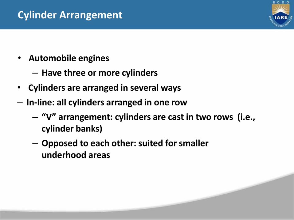
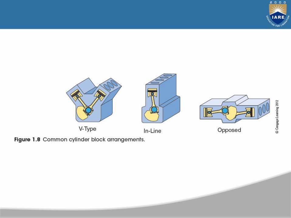
Cylinder Arrangement
• Automobile engines
– Have three or more cylinders
• Cylinders are arranged in several ways
– In-line: all cylinders arranged in one row
– “V” arrangement: cylinders are cast in two rows (i.e., cylinder banks)
– Opposed to each other: suited for smaller underhood areas

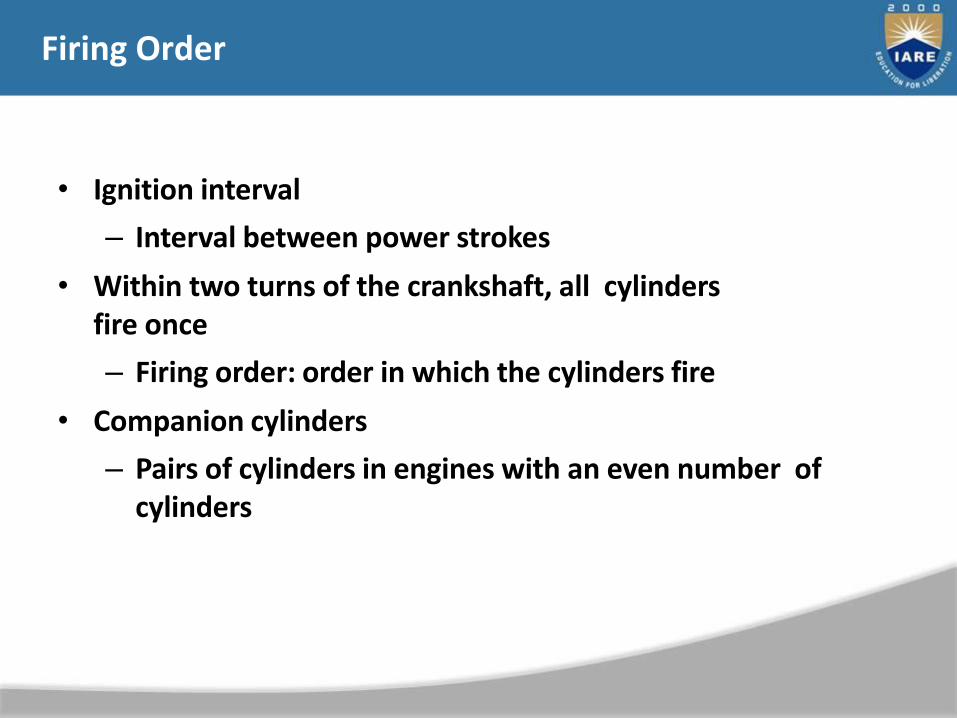
Firing Order
• Ignition interval
– Interval between power strokes
• Within two turns of the crankshaft, all cylinders fire once
– Firing order: order in which the cylinders fire
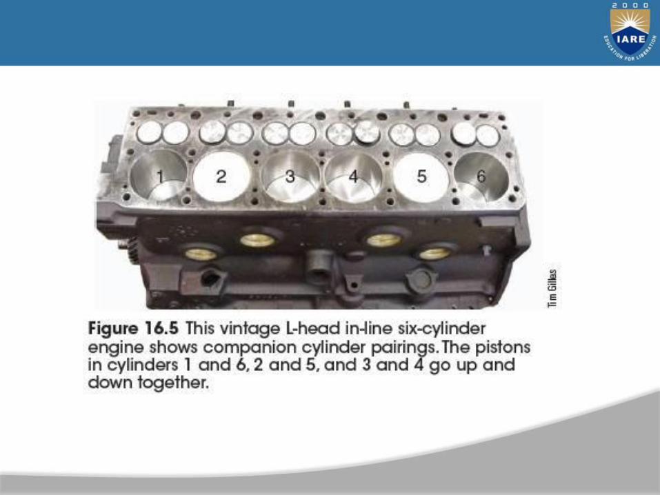
• Companion cylinders
– Pairs of cylinders in engines with an even number of cylinders
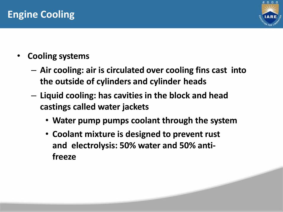
Engine Cooling
• Cooling systems
– Air cooling: air is circulated over cooling fins cast into the outside of cylinders and cylinder heads
– Liquid cooling: has cavities in the block and head castings called water jackets
• Water pump pumps coolant through the system
• Coolant mixture is designed to prevent rust and electrolysis: 50% water and 50% anti-freeze

Valve Location
• Engines are classified by valve location
• Common arrangements
– L-head: common in motor vehicles during the first half of the twentieth century
– I-head: used in today’s automobiles
• Less exhaust emissions
• Higher compression
Camshaft Location
• Cam-in-block engine: pushrod engine
– Camshaft has valve lifters that move pushrods that operate rocker arms to open the valves
– Found most often on V-type engines
• Cam-in-head engine: overhead cam engine
– Camshaft is mounted on top of the cylinder head, just above the valve
– Found in in-line engines
Other Cylinder Head Variations
• Crossflow head: intake and exhaust manifolds are on opposite sides on an in-line engine
– More efficient in moving intake and exhaust
• High-performance breathing arrangements
– Designs can improve engine breathing
• High-performance late-model engines use multiple valve heads
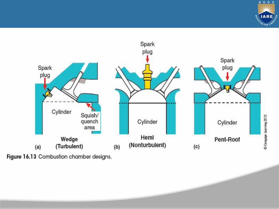
Combustion Chamber Designs
• Common combustion chamber designs– Hemi (nonturbulent): efficient at high speeds– Wedge (turbulent): common in pushrod engines
• Other chamber designs– Pent-roof (V-shaped)– Chambers shaped like a “D” or a heart
• Diesel engines– No chamber in the cylinder head itself
• Honda– Designed a stratified charge design

Spark and Compression Ignition
• Diesel-cycle and four-stroke gasoline engines
– Share the same basic principles
• Gasoline engine: spark ignition (S.I.) engine
• Diesel, compression ignition engines: do not use a spark to ignite fuel
• Diesel engines
– Compression ratio: comparison between volume of cylinder and combustion chamber
– Can run at very lean air-fuel mixtures at idle
– Have high particulate emissions


Alternate Engines
• Most vehicles use internal combustion four- stroke
piston engines
– Several other engine types have been developed
• Alternate engines found in today's vehicles:
– Wankel rotary (rotary engine): two rotors rotate inside of a chamber
• Do not have pistons
– Two-stroke cycle engines: use a mixture of oil and gasoline for lubrication of the crankshaft, connecting rod, and piston
New Generation Vehicles
• Include:
– ULEVs: ultra-low emission vehicles
– ZEVs: zero emission vehicles
– EVs: electric vehicles
– PEVs: plug-in electric vehicles
• Battery EVs and hybrid EVs: several concerns
– Must carry many nickel metal hydride or lithium-ion batteries (LIBs), which are heavy
– Specialized hazard and safety training for emergency service personnel is needed

Regenerative Braking
• During deceleration
– Motor is used as a generator, producing electricity to recharge batteries as it slows the vehicle down
Hybrid Vehicles
• Advantages– Improved fuel economy– Increased performance– Reduction in exhaust pollutants
• Most are powered with an internal combustion engine or a battery-powered electric motor
• Hybrid combinations– Series hybrid– Parallel hybrid– Series/parallel hybrid
• Major operating difference between hybrid and conventional vehicles powered only by an engine
– Engine in a hybrid vehicle stops running at idle as long as certain operating conditions are met
• Improves fuel economy
• Hybrid disadvantages
– High initial costs
– Technician safety concern

Types of Hybrids
• Mild hybrid
– Vehicle moves with power supplied only by ICE
• Medium hybrid
– Added function of electric motor assist
• Full hybrids
– Do everything that medium hybrids do,
– Can also power vehicle using only the electric motor
– Includes two-mode hybrids
• Power hybrid/muscle hybrid
– As motor speeds up but its torque remains the
same, the engine provides supplementation
• Plug-in hybrid
– Power socket allows larger batteries to be recharged by an external source of electricity
• Plug-in recharging
– Electrical grid: interconnected network
• Moves electricity from generating stations to customers

Hybrid Vehicle Service and Safety
• Considerations
– Electrical shock hazard
• Conduit color designations
• Other hybrid vehicle operation, safety, and service
– More information can be found in other chapters

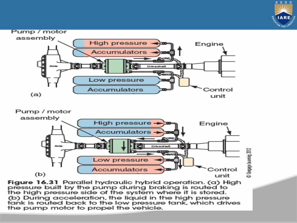
Hydraulic Hybrid Vehicles
• Work in the same manner as HEVs
– Increase overall efficiency
• Run engine at its most efficient rpm
• Capture energy during braking
• Shut engine off whenever possible
– Use reservoirs, accumulators, and pumps
• Instead of batteries
• Hydraulic hybrid system operation
– High-pressure fluid is stored in accumulators at
pressures above 3,000 psi
• Generate electricity when needed
– Only exhaust by-products are water and heat
• PEM: proton exchange membrane fuel cell
– Possible internal combustion engine replacement
• Technically hybrid vehicles
– Use an electricity-generating fuel cell engine rather than an ICE
– Has a backup battery module
– Use an electrochemical reaction to produce electricity
Fuel Cell Electric Vehicles (FCEVs)
• Fuel cell operation
– Use hydrogen for fuel and oxygen from the air as an oxidant
• Combining hydrogen and oxygen produces electricity
• Fuel cell characteristics
– Never run dead
– Stacked and connected in series
– Some use an ultracapacitor
– Expensive to replace
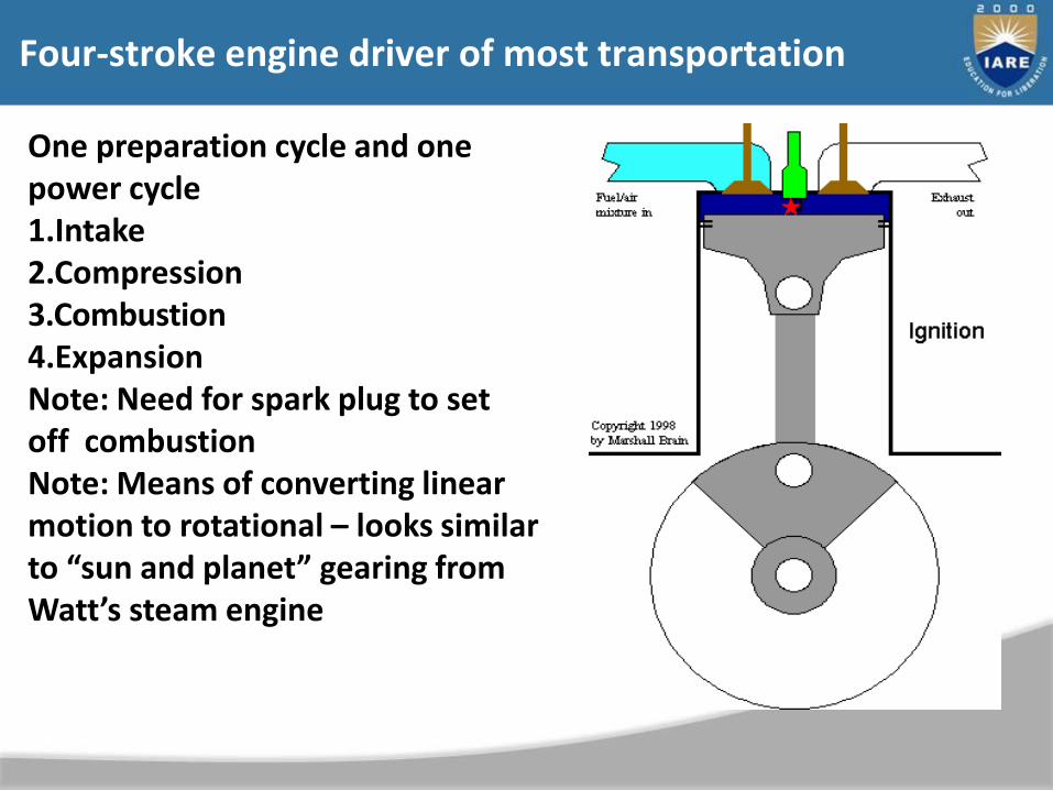
Four-stroke engine driver of most transportation
One preparation cycle and one power cycle1.Intake 2.Compression 3.Combustion4.ExpansionNote: Need for spark plug to set off combustionNote: Means of converting linear motion to rotational – looks similar to “sun and planet” gearing from Watt’s steam engine

Four-stroke engine driver of most transportation
Advantages:Produces heated, compressed, very dense fuel/air mixture
Disadvantages:“off” half the time – half the power-to-mass ratio that it might haveMust have at least two cylinders, since when one is “off” the other must be providing the push to keep rotating the shaft
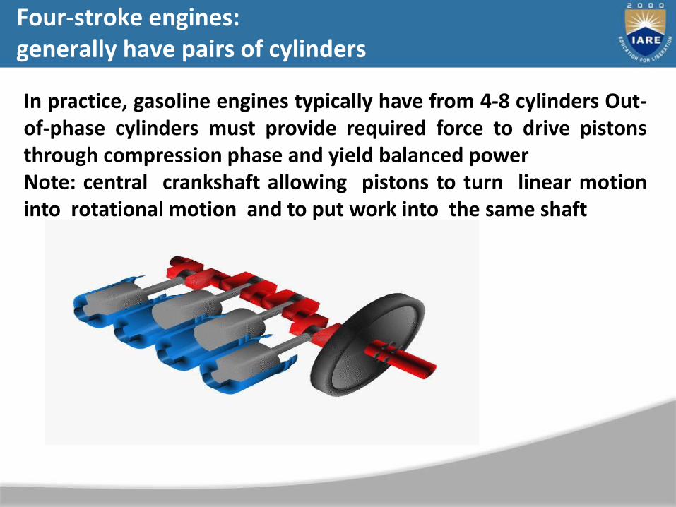
Four-stroke engines: generally have pairs of cylinders
In practice, gasoline engines typically have from 4-8 cylinders Out-of-phase cylinders must provide required force to drive pistonsthrough compression phase and yield balanced powerNote: central crankshaft allowing pistons to turn linear motioninto rotational motion and to put work into the same shaft
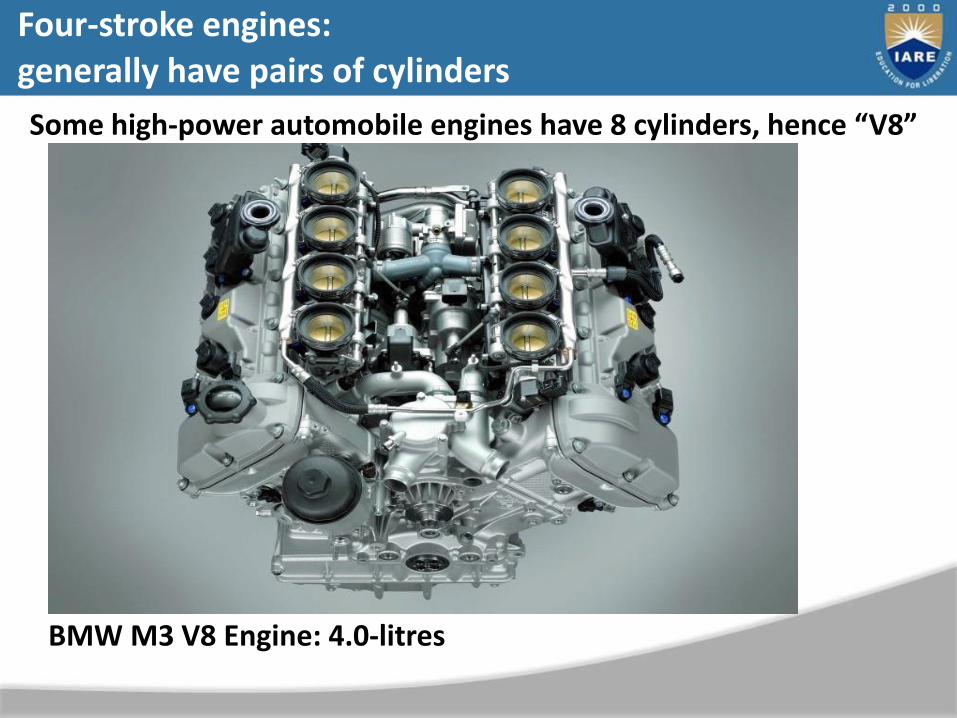
Some high-power automobile engines have 8 cylinders, hence “V8”
BMW M3 V8 Engine: 4.0-litres
Four-stroke engines: generally have pairs of cylinders
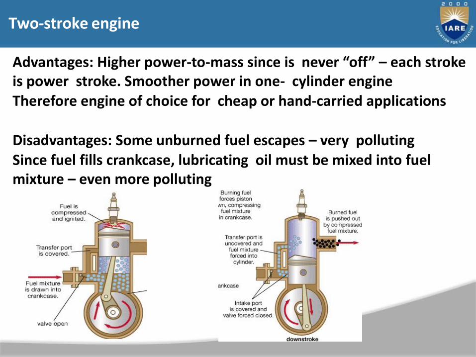
Two-stroke engine
Advantages: Higher power-to-mass since is never “off” – each stroke is power stroke. Smoother power in one- cylinder engineTherefore engine of choice for cheap or hand-carried applications
Disadvantages: Some unburned fuel escapes – very pollutingSince fuel fills crankcase, lubricating oil must be mixed into fuel mixture – even more polluting
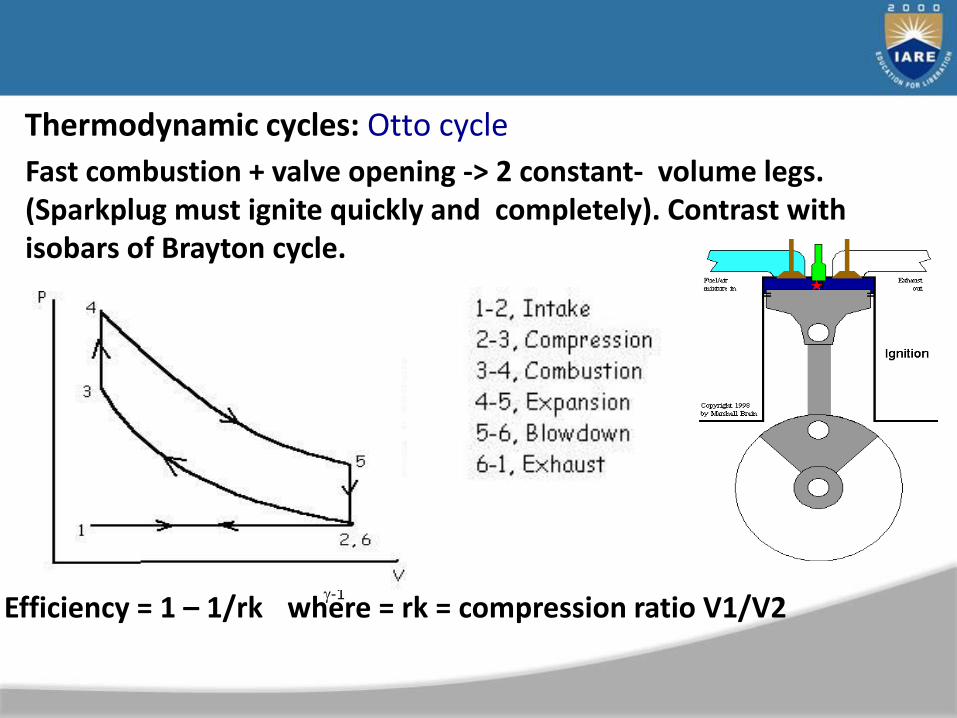
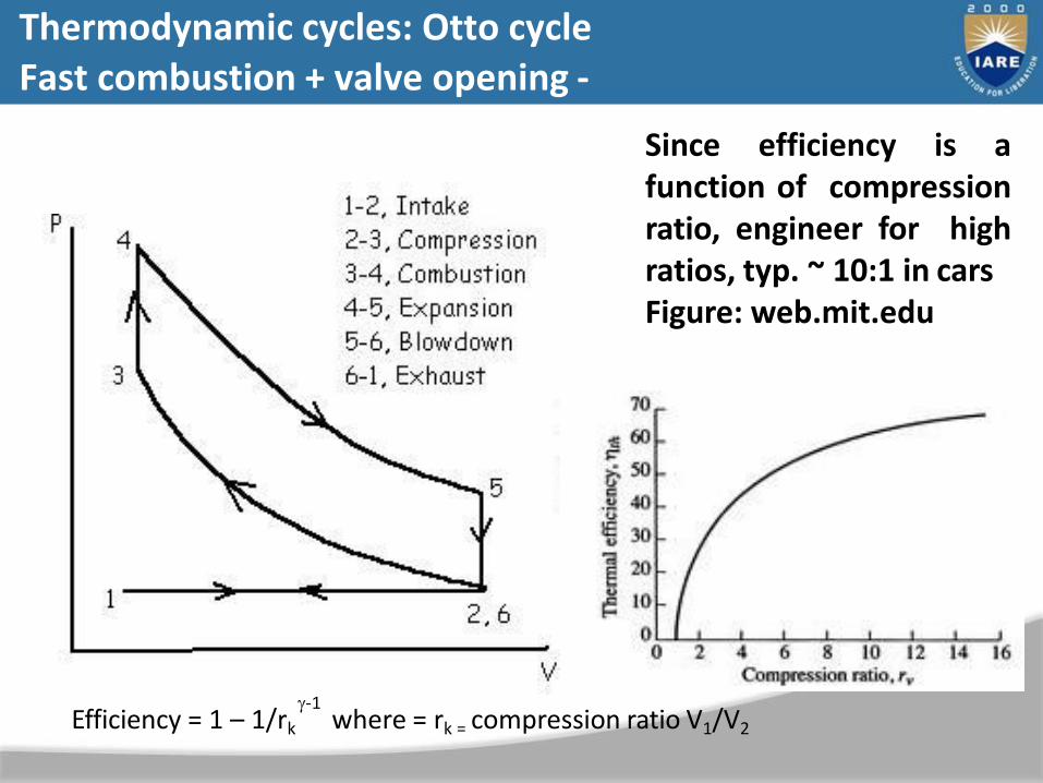
Thermodynamic cycles: Otto cycle
Fast combustion + valve opening -> 2 constant- volume legs. (Sparkplug must ignite quickly and completely). Contrast with isobars of Brayton cycle.
-1Efficiency = 1 – 1/rk where = rk = compression ratio V1/V2
-1Efficiency = 1 – 1/rk where = rk = compression ratio V1/V2
Since efficiency is afunction of compressionratio, engineer for highratios, typ. ~ 10:1 in carsFigure: web.mit.edu
Thermodynamic cycles: Otto cycleFast combustion + valve opening -
UNIT–IICOOLING SYSTEM
65
66
CLOs Course Learning Outcome
CLO4 Compare the different cooling processes in I.C engines,working of radiator and cooling accessories..
CLO5 Analyse the different spark ignition system advantagesof each individual system.
CLO6 Understand the working of different automobilecomponents like lighting system, horn, wiper, fuel gauge,temperature indicator.
Cooling System Service Objectives
• Diagnose cooling system problems
• Service all parts of the cooling system
Introduction
• Cooling systems are dependable
– Require periodic maintenance
• Coolant system service
– Best value in terms of preventative maintenance
• Working on cooling systems is not difficult
– Sometimes very profitable

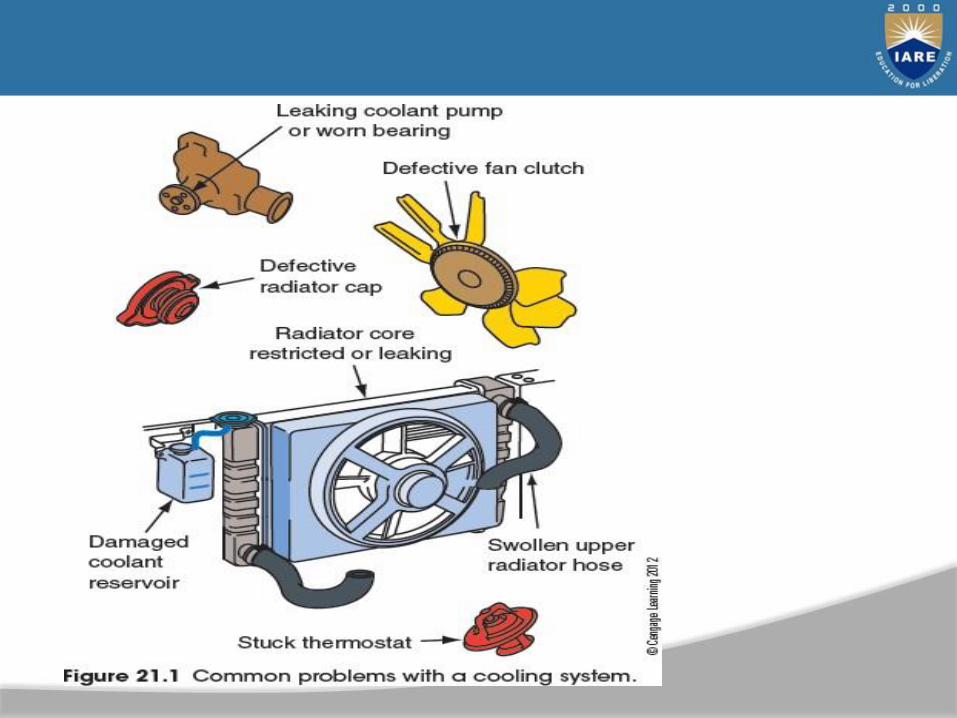
Diagnosing Cooling System Problems
• Causes of cooling system problems:
– Coolant level
– Restricted radiator
– Stuck thermostat
– Defective water pump
– Fan shroud
– Frozen coolant
– Defective cooling fan
– Exhaust blockage
– Inoperative EGR valve

Radiator Cap
• Damaged cap allows pressure to escape
– Boiling point may drop causing boil over
– Pressure tester tests the cap’s pressure valve
• Radiator inspection
– Inspect for leaks, damage, and obstructions
• Coolant should fill entire radiator opening as it flows
• Check condition of fins by rubbing gently
• Broken engine mount can cause excessive movement
• Leaks from heat exchanger cause transmission fluid to be pumped into radiator
Coolant Service
• Coolant loses protective ability and becomes corrosive
– Check cold coolant for grease, dirt, rust, and corrosion bloom
– Electrolysis makes small holes in parts
• Cooling conductivity is checked with voltmeter
• Voltmeter reading should be less than 0.4
• Also caused by poor electrical conductivity in ground circuit
– Coolant should be changed every 30,000 miles
– Most radiators have plastic drain valves
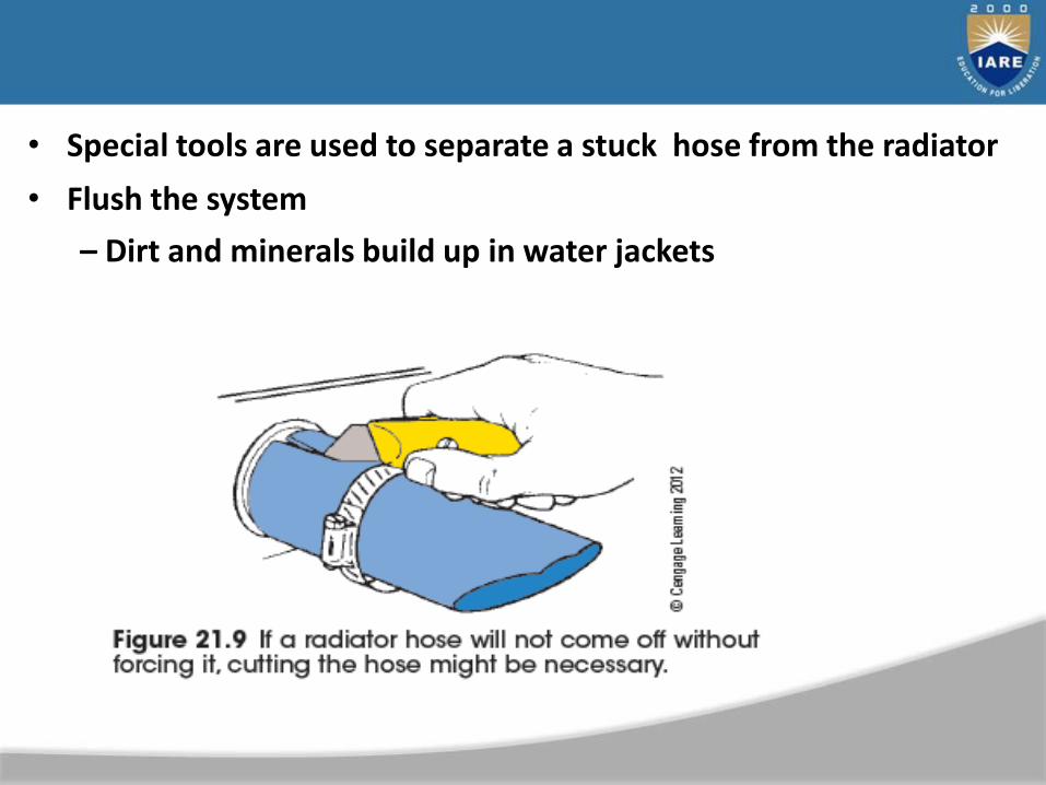
• Special tools are used to separate a stuck hose from the radiator
• Flush the system
– Dirt and minerals build up in water jackets

• Airlift leak check and airlock purge– Venturi system: uses compressed air to create a vacuum in the
cooling system
• Effective way to check for leaks and refill the cooling system
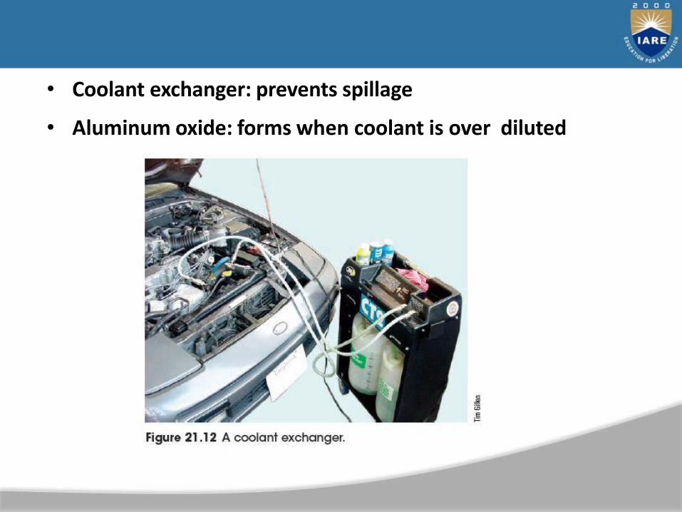
• Coolant exchanger: prevents spillage
• Aluminum oxide: forms when coolant is over diluted
Testing Coolant Condition and Strength
• Coolant test strips
– Test the condition of the coolant
• Coolant alkalinity (pH)
– Coolant must continue to contain reserve alkalinity
• Coolant density testers
– Measure a coolant’s freeze point
• Hydrometers and refractometers
– Test coolant concentration
• Several coolant types
– DexCool and HOAT coolant
Thermostat Service
• Test in the vehicle
– Hand-held multimeter or putting it into coolant
• Thermostat check after removal
– Lower into hot water with a thermometer
• Good thermostats: fully closed when cold and fully open near its rating
– When removing: drain until level is below thermostat housing first
– When replacing: be sure the thermostat fits into the groove in the block or outlet housing
• Bleed air from the system to prevent overheating
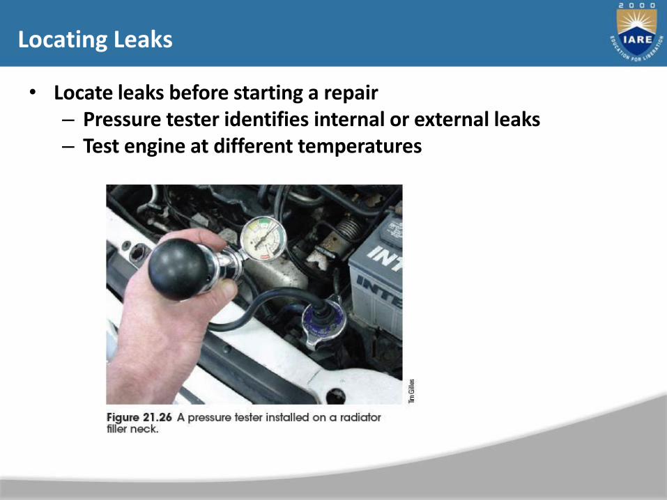
Locating Leaks
• Locate leaks before starting a repair– Pressure tester identifies internal or external leaks– Test engine at different temperatures

External Leaks
• Check for external leaks:
– Heater core and hoses
– Radiator hoses
– Thermostat housing and core plugs
– Radiator and coolant pump
• Core plug inspection
– Common: rust and leakage
• Coolant outlet (thermostat) housing inspection
– Inspect for leaks or damage
Internal Leaks
• Bubble test– Look for bubbles in radiator when engine is warm
• Hydrostatic lock
– Engine stops with a piston down with valves closed and crankshaft will not turn
• Block check test– Samples air in the radiator filler neck– Carbon monoxide changes the color of the tester
• Infrared analyzer
– Checks for exhaust gas in the coolant
Recovery Tank Service
• Most cooling systems have a plastic coolant reservoir or recovery tank
– Recycles the coolant
– Helps decrease corrosion
• During a cooling system flush
– Recovery tank or auxiliary reservoir is flushed of contaminants
Cooling System Repairs
• Replacing core plugs
– Pound it sideways with a blunt drift punch
– Do not leave an old core plug inside the block
• Core plug installation
– Clean the block opening with an emery cloth
– Apply sealer to sides of new plug
– Pound in with a driver or socket that fits loosely into the inside diameter of plug
Water Pump Service
• Coolant pump leakage: visible from vent hole
• Worn bearing: use a stethoscope to listen for bad bearing
• Worn or broken impeller: indicated with water pump action in radiator of warm, running engine
• Water pump replacement: before installing, remove all fasteners
– Inspect the old pump, select a new one, install, and refill

Fan Inspection
• Out-of-balance fan assembly leads to cooling pump shaft and bearing failure
• Possible sources of pump failure– Leaking fan clutch– Bent or broken fan– Cocked or cracked aluminum fan spacer
• Clean all mating surfaces and tighten fan bolts evenly to avoid cocked assembly
• Fan clutch inspection– Fluid leaks and see if it is loose or frozen

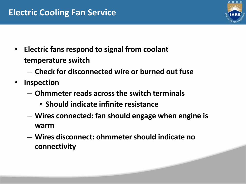
Electric Cooling Fan Service
• Electric fans respond to signal from coolant
temperature switch
– Check for disconnected wire or burned out fuse
• Inspection
– Ohmmeter reads across the switch terminals
• Should indicate infinite resistance
– Wires connected: fan should engage when engine is warm
– Wires disconnect: ohmmeter should indicate no connectivity

Heater Core Service
• Heater core
– May leak or become plugged
– Supplied with engine coolant through two hoses
– Heat demands: controlled by doors to ducts around heater core
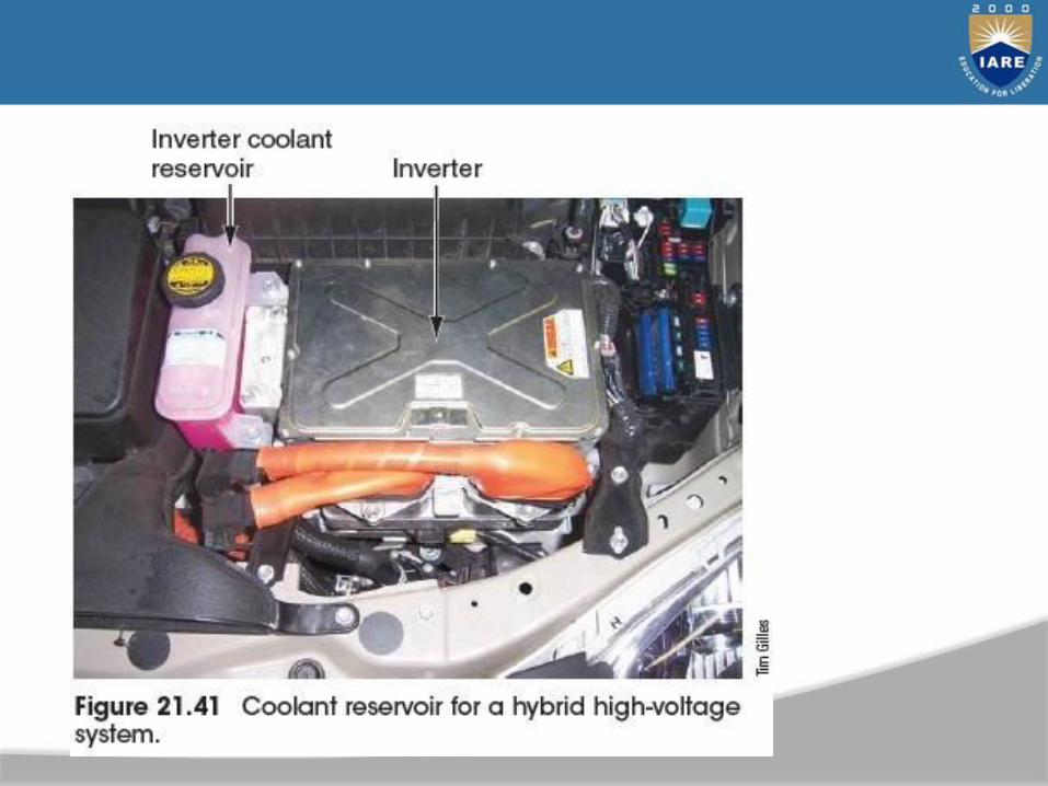
• Hybrids cooling systems
– Powered by electric motors that do not produce heat when the engine is shut off
• Coolant system does not have to deal with heat load
Ignition Systems

• Chat about Ignition Systems
• Demo Ignition Tools
• Spark Plug Testing Activity
Outline
• Magnets and electricity
• Ignition components
• Basic ignition system operation
• Types of ignition systems
• Solid state ignition system
Magnets and Electricity
• Conductor – A material or an object that allows electricity to flow easily Ex: Gold, copper, aluminum
• Insulator – A material or an object that don’t allow electricity to flow easily Ex: Glass, Porcelain, wood
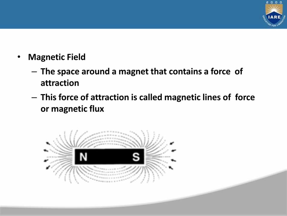
• Magnetic Field
– The space around a magnet that contains a force of attraction
– This force of attraction is called magnetic lines of force or magnetic flux

• If a conductor, such as copper, is moved so that it cutsmagnetic lines of force, an electron flow is induced in theconductor
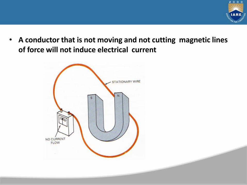
• A conductor that is not moving and not cutting magnetic lines of force will not induce electrical current
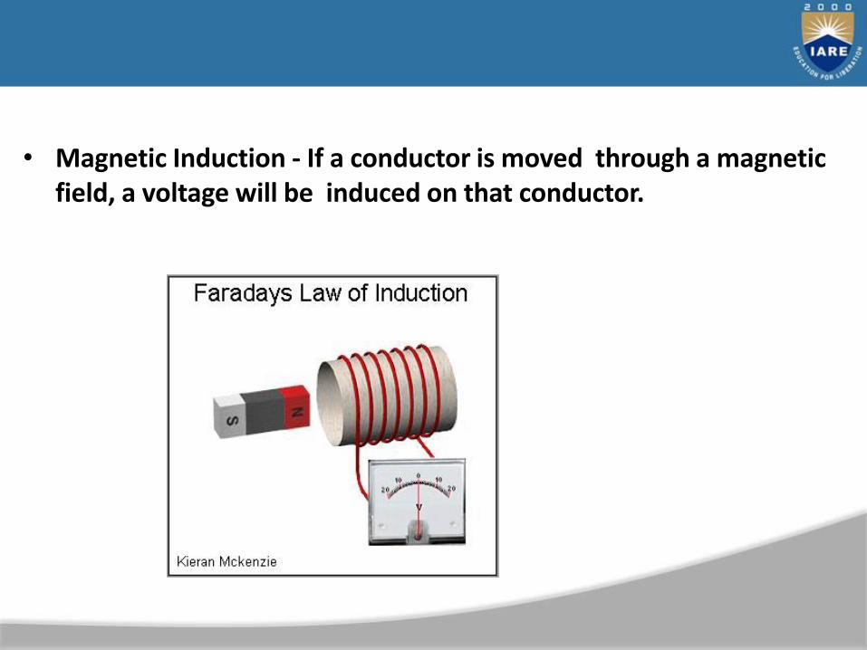
• Magnetic Induction - If a conductor is moved through a magnetic field, a voltage will be induced on that conductor.
Ignition Components
• Switch – electrical device that turns the current on and off
• Capacitor (condenser) – electrical component
that can store an electric charge.
• Diode Rectifier – Changes alternating current to direct current
• Silicon-controlled Rectifier (SCR) – consists of a diode and transistor and is used as a switching device in electronic circuits
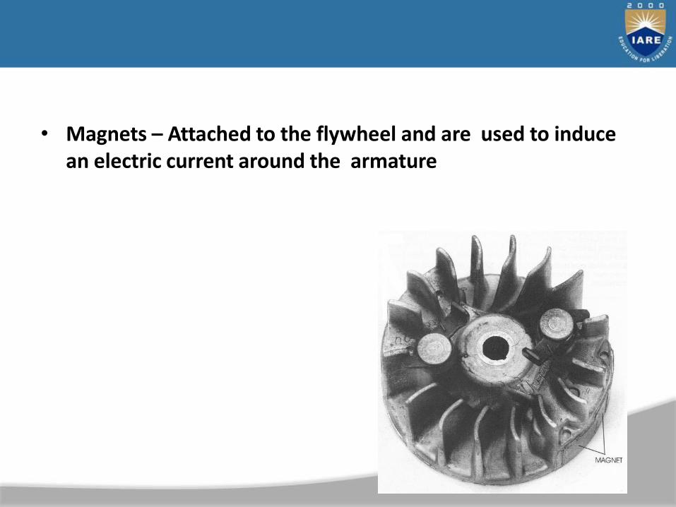
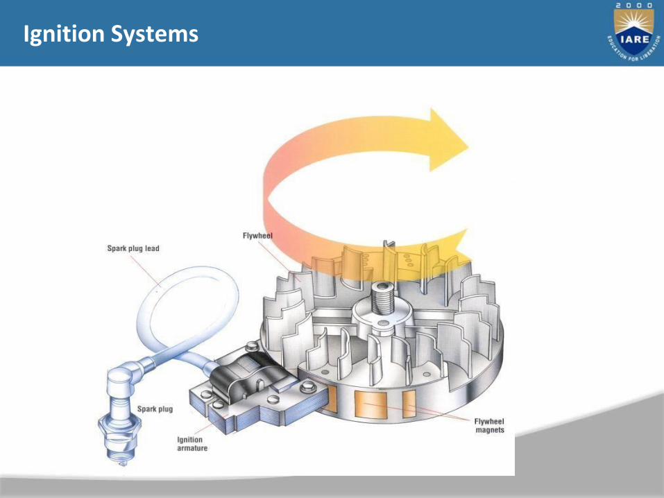
• Magnets – Attached to the flywheel and are used to induce an electric current around the armature
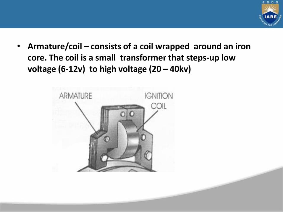
• Armature/coil – consists of a coil wrapped around an iron core. The coil is a small transformer that steps-up low voltage (6-12v) to high voltage (20 – 40kv)
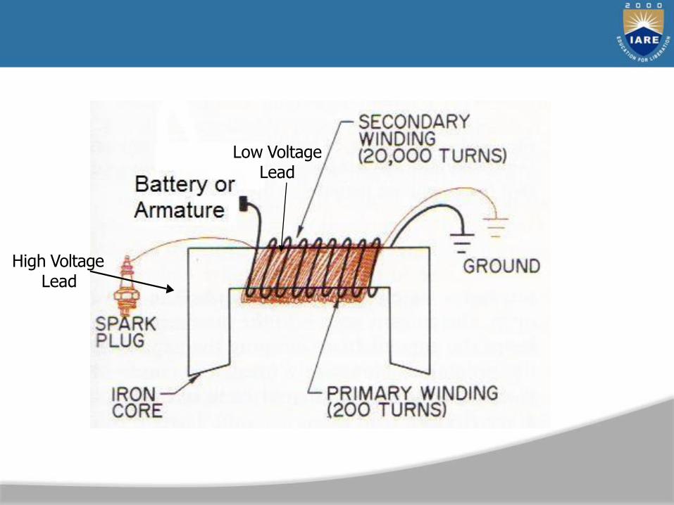
High Voltage Lead
Low VoltageLead
• Primary Winding
– Thick wire that is wrapped around the core between 150 and 200 times.
– The primary winding is the low voltage wire that carries 6-12 volts
Ignition Components
• Secondary Windings
– Thin wire that is wrapped around the primary winding about 20,000 times
– The secondary winding is the high voltage wire that carries 20,000 – 40,000 volts
• Low Voltage Lead – carries low voltage from the battery or armature to primary side of coil
• High Voltage Lead – carries high voltage from the secondary side of the coil to the spark plug
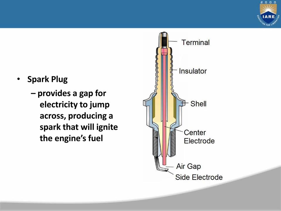
• Spark Plug
– provides a gap for electricity to jump across, producing a spark that will ignite the engine’s fuel
Basic Ignition System Operation
• As the flywheel spins, the magnets move close to the armature/coil.
• The magnetic field induces an electrical current in the primary windings
• The current induces a voltage in the secondary winding
• When the current flow through the primary winding is stopped the magnetic field collapses rapidly and will induce a high voltage current in the secondary winding.
• The current then runs directly to the spark plug andcauses a spark to jump across the spark plug gap.
Ignition Tools
• Micrometer
• Caliper
• Feeler Gauge
• Spark plug tester (Ignition tester)
• Spark plug wrench
• Flywheel holder
• Torque Wrench
• Dial Bore Gauge
Three Types of Ignition Systems
1. Magneto Ignition System
2. Battery Ignition System
3. Solid State Ignition System

Magneto Ignition System
• Generates power through magnetic induction.
• Contains mechanical components (breaker points) that perform the switching action in the ignition circuit

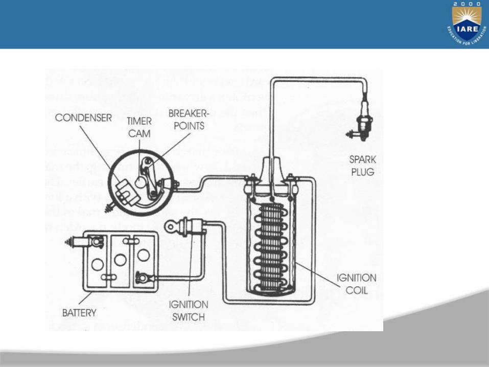
Battery Ignition System
• A battery is used to provide power to the ignition circuit instead of magnetic induction.
• Uses either mechanical or electrical components to perform the switching action in the ignition circuit
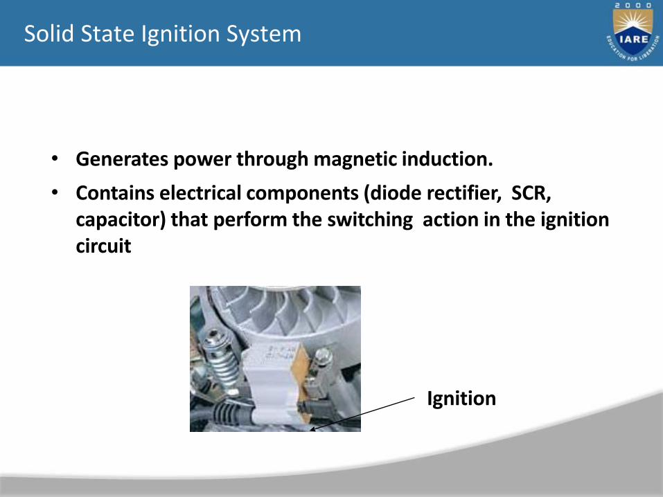
Solid State Ignition System
• Generates power through magnetic induction.
• Contains electrical components (diode rectifier, SCR, capacitor) that perform the switching action in the ignition circuit
Ignition
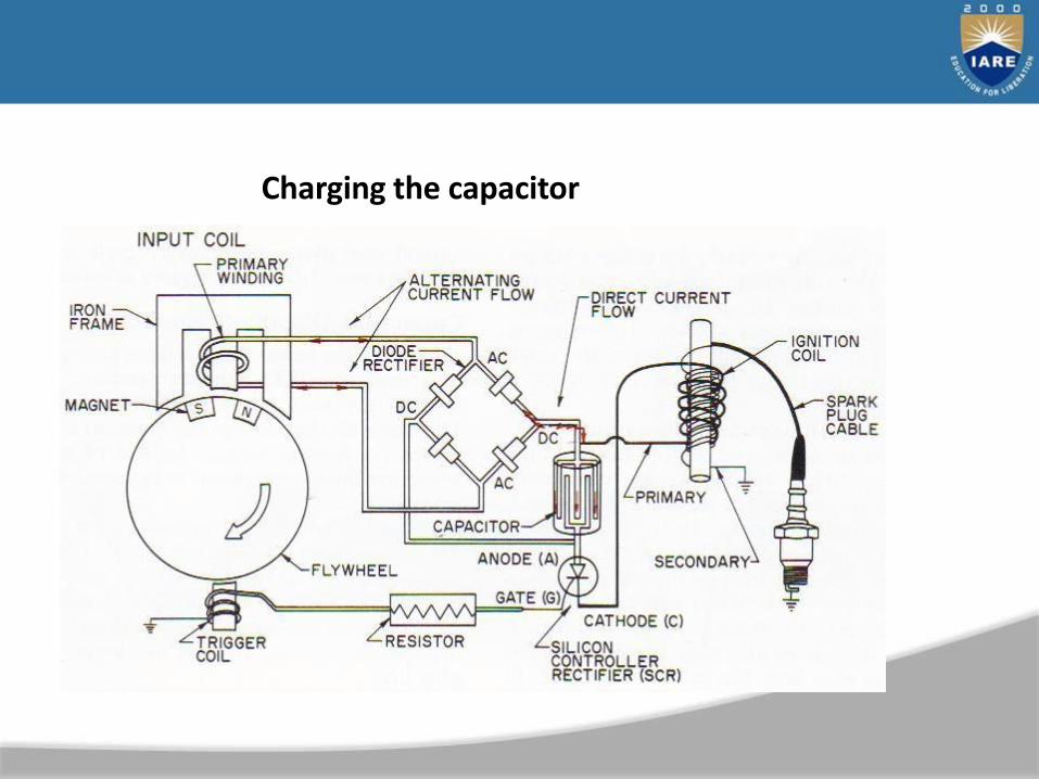
Charging the capacitor
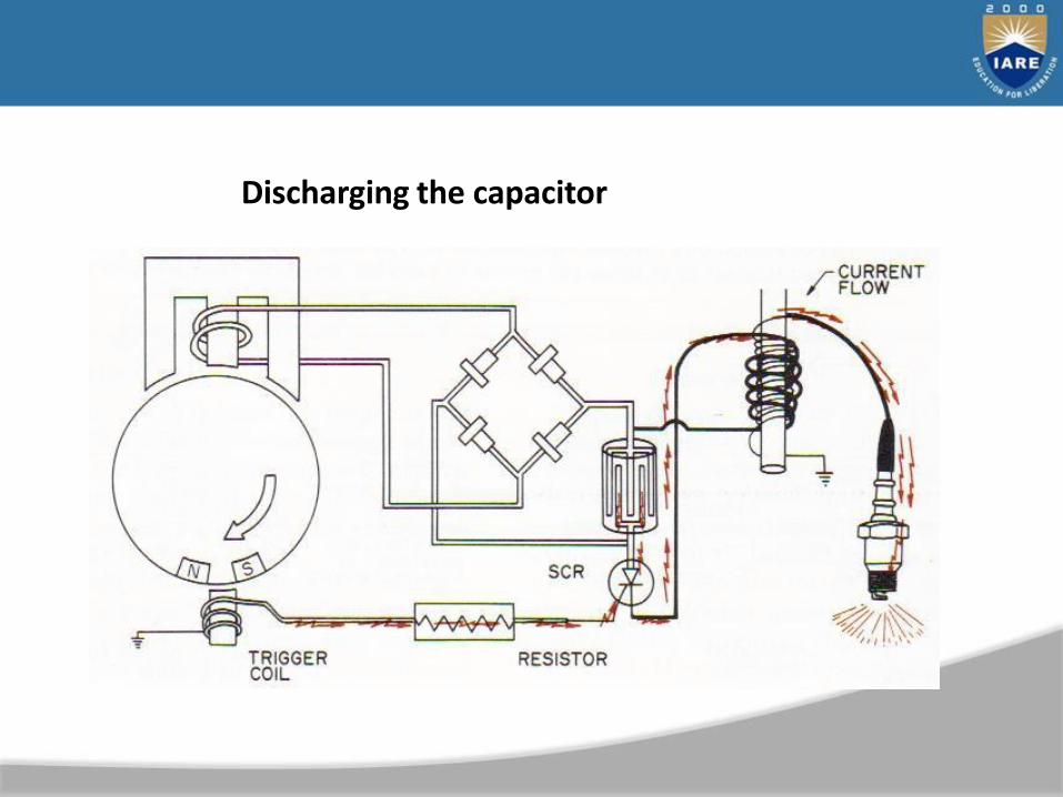
Discharging the capacitor

• The ignition switch is in the on position and a low voltage alternating current (AC) is produced in the charge coil by the flywheel magnets.
• The AC current passes through the rectifier and is changed to direct current (DC).

• Which then travels to the condenser where it is stored temporarily.
• The flywheel magnets pass the trigger coil and produce a small electrical charge which turns on the silicon controlled rectifier (SCR).

• The SCR now permits the current to flow to the primary winding of the ignition coil producing a strong magnetic field.
• The production of this magnetic field is sufficient to cause a high voltage induction in the secondary windings of the ignition coil.
• The current then travels to the spark plug and arcs across the air gap.
UNIT–IIITRANSMISSION AND SUSPENSION SYSTEMS
120
121
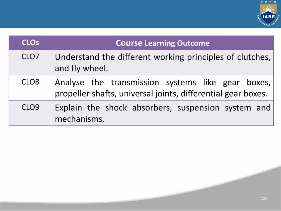
CLOs Course Learning Outcome
CLO7 Understand the different working principles of clutches,and fly wheel.
CLO8 Analyse the transmission systems like gear boxes,propeller shafts, universal joints, differential gear boxes.
CLO9 Explain the shock absorbers, suspension system andmechanisms.
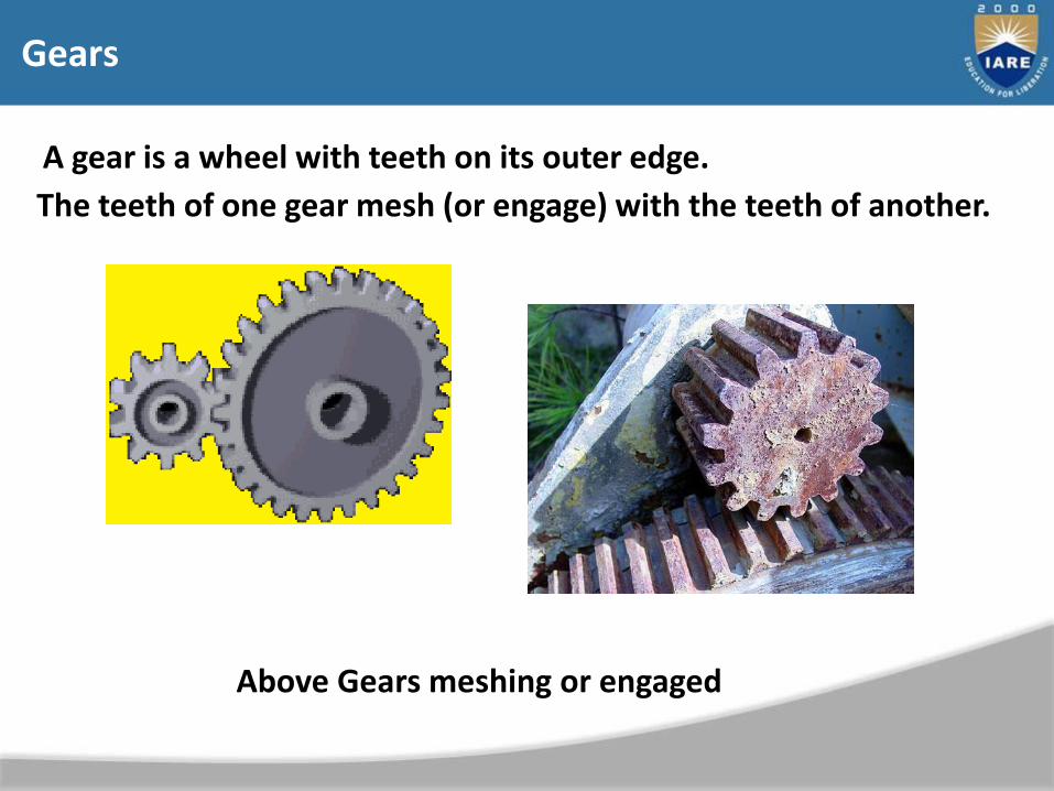
Gears
A gear is a wheel with teeth on its outer edge.
The teeth of one gear mesh (or engage) with the teeth of another.
Above Gears meshing or engaged

Driver and Driven
Driver gearDriven gear
• Two meshed gears always rotate in opposite directions.
Spur Gears
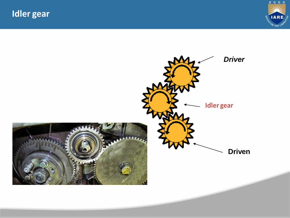
Idler gear
Driver
Driven
Idler gear
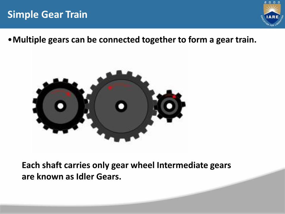
•Multiple gears can be connected together to form a gear train.
Simple Gear Train
Each shaft carries only gear wheel Intermediate gears are known as Idler Gears.
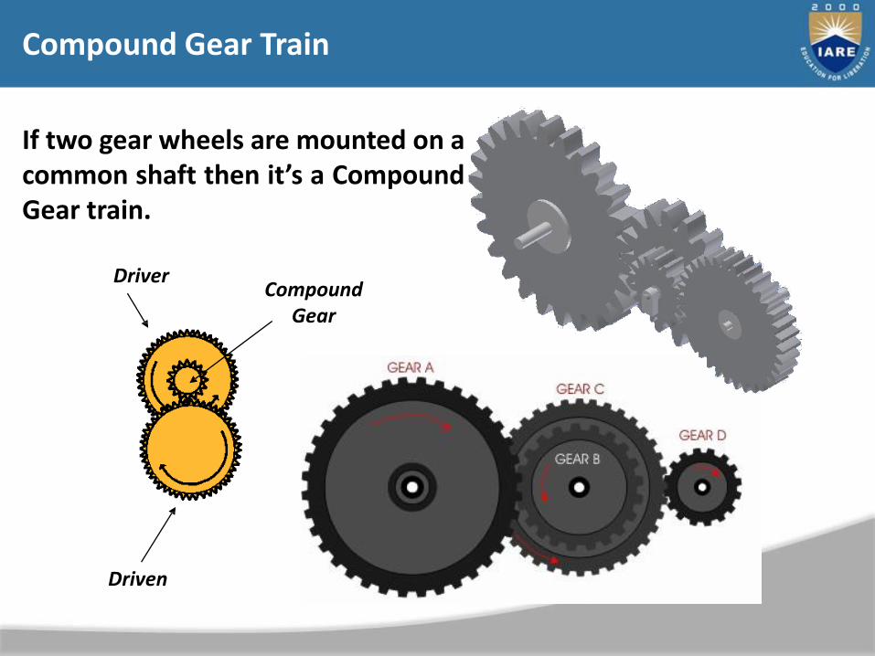
Compound Gear Train
DriverCompound
Gear
Driven
If two gear wheels are mounted on acommon shaft then it’s a CompoundGear train.
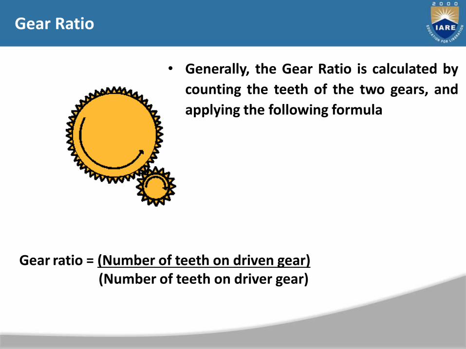
• Generally, the Gear Ratio is calculated by
counting the teeth of the two gears, and
applying the following formula
Gear Ratio
Gear ratio = (Number of teeth on driven gear)(Number of teeth on driver gear)

Gear Ratio - Calculation
A 100 tooth gear drives a 25 tooth gear. Calculate the gear ratio for the meshing teeth.
Gear ratio = =driven 25
driver 100
1
4
This is written as 1:4
Gear ratio = (Number of teeth on driven gear)(Number of teeth on driver gear)
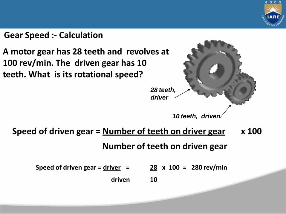
Gear Speed :- Calculation
A motor gear has 28 teeth and revolves at 100 rev/min. The driven gear has 10 teeth. What is its rotational speed?
Speed of driven gear = driver =
driven
28 x 100 = 280 rev/min
10
28 teeth,
driver
10 teeth, driven
Speed of driven gear = Number of teeth on driver gear x 100
Number of teeth on driven gear
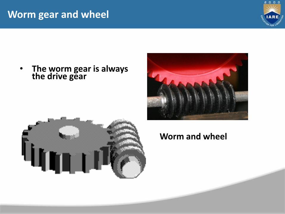
• The worm gear is always the drive gear
Worm and wheel
Worm gear and wheel
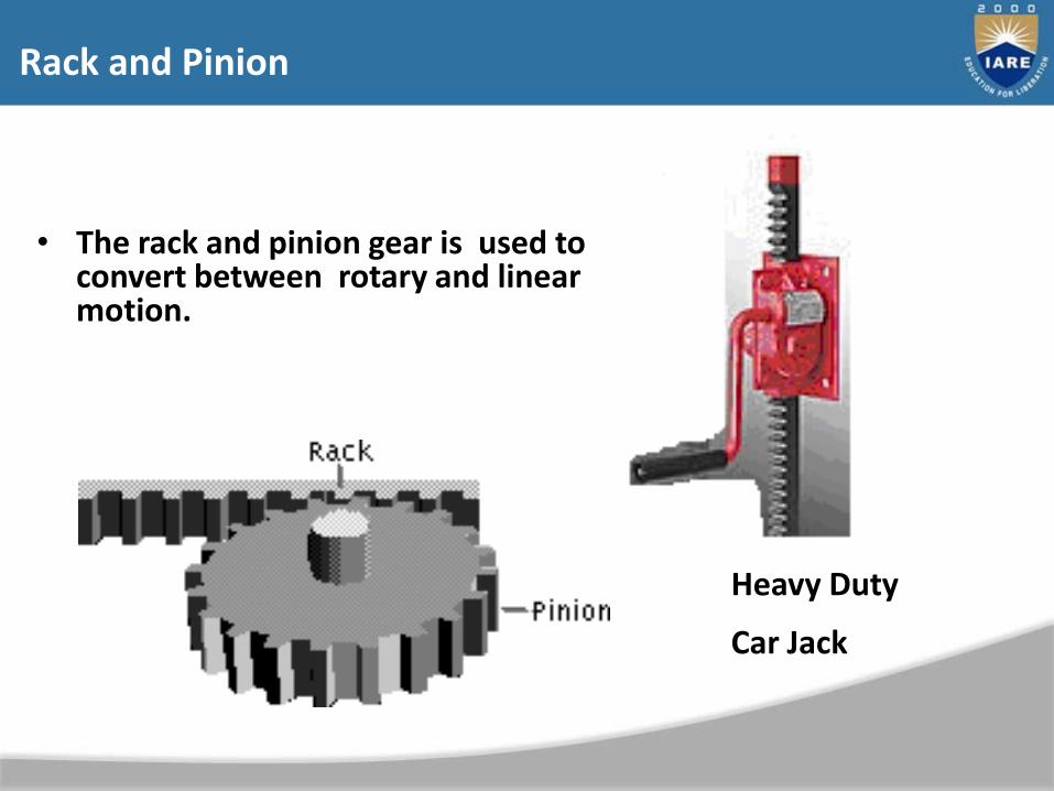
• The rack and pinion gear is used to convert between rotary and linear motion.
Rack and Pinion
Heavy Duty
Car Jack
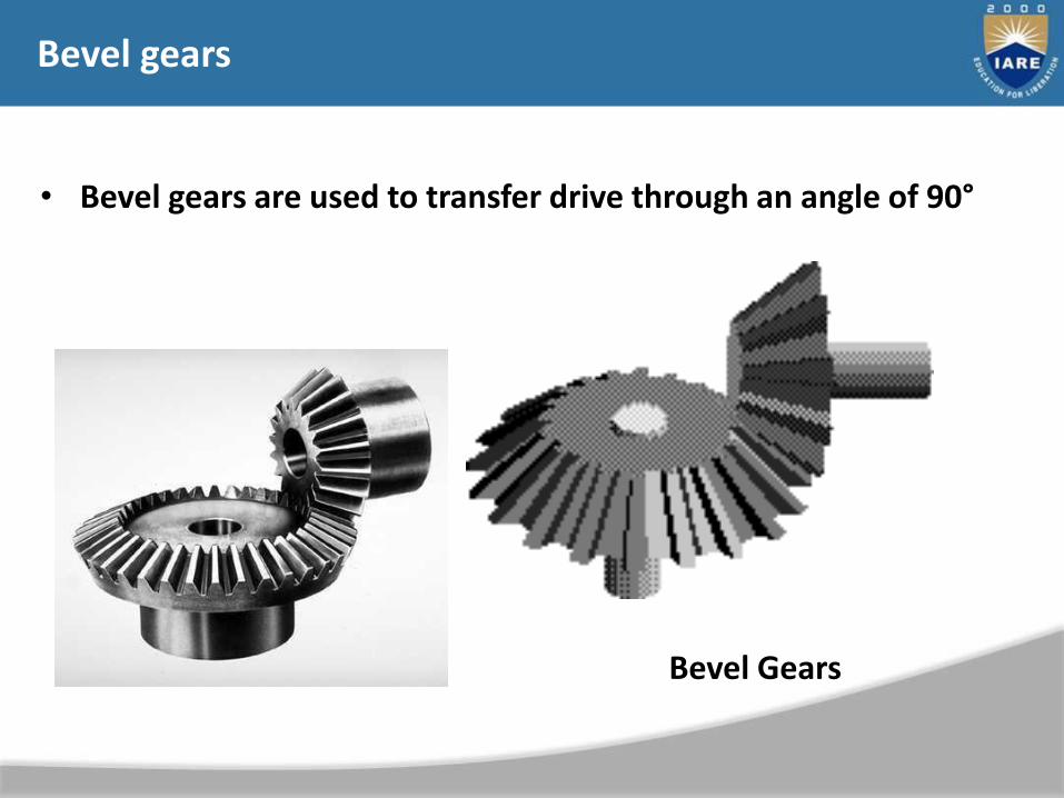
• Bevel gears are used to transfer drive through an angle of 90°
Bevel Gears
Bevel gears
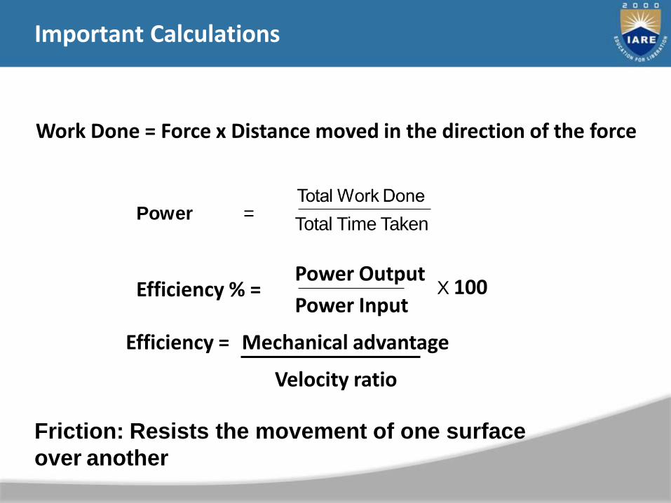
Important Calculations
Power =Total Time Taken
Work Done = Force x Distance moved in the direction of the force
Efficiency % =Power Output
Power InputX 100
Efficiency = Mechanical advantage
Velocity ratio
Friction: Resists the movement of one surface
over another
Gear trains
• Change torque, speed
• Why we need gears
• Example: engine of a containership
– Optimum operating speed of the engine about 400 RPM
– Optimum operating speed of the propeller about 100 RPM
– Need reduction gear
130
131
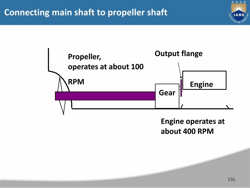
EngineGear
Propeller,operates at about 100
RPM
Output flange
Engine operates at about 400 RPM
Connecting main shaft to propeller shaft
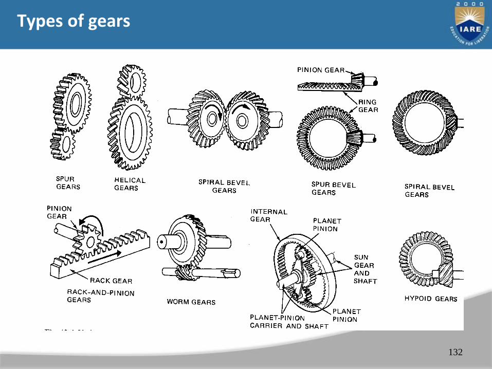
Types of gears
132
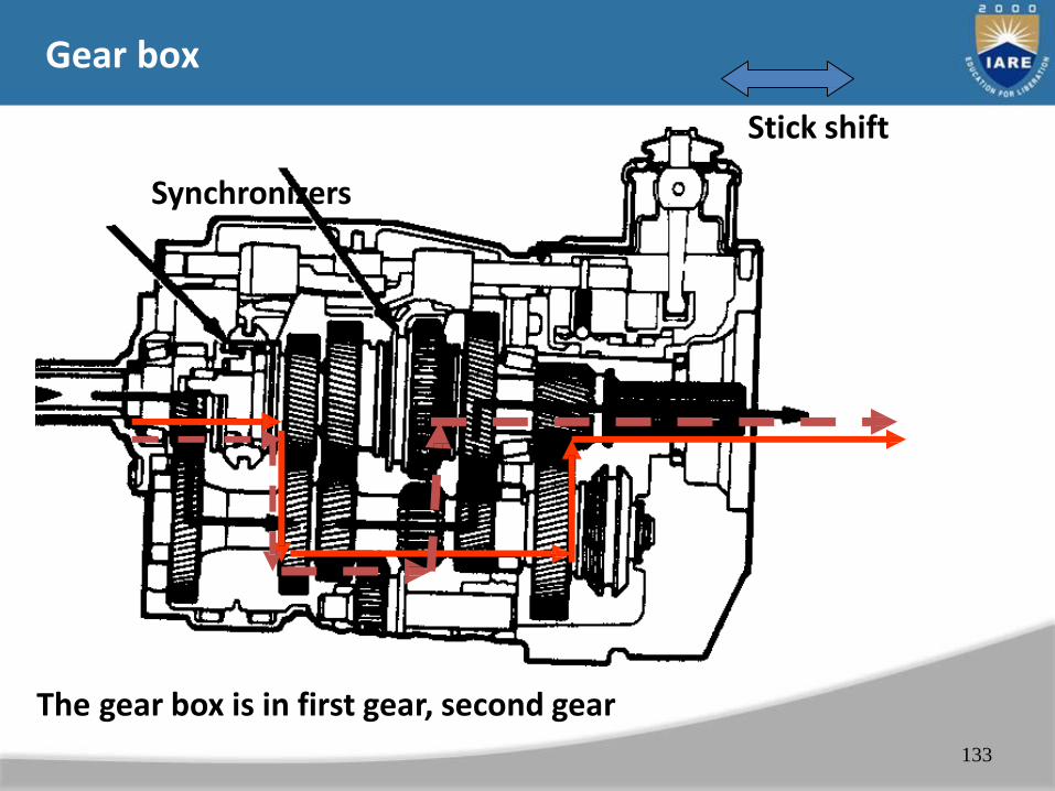
Gear box
133
Synchronizers
Stick shift
The gear box is in first gear, second gear
134
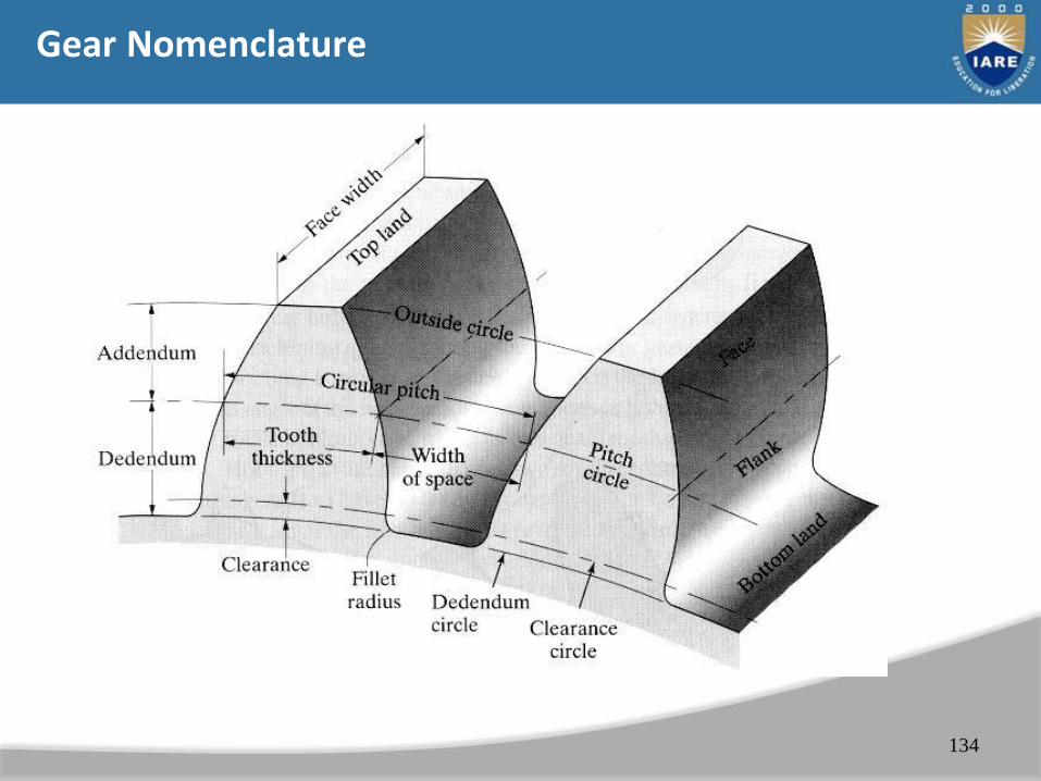
Gear Nomenclature
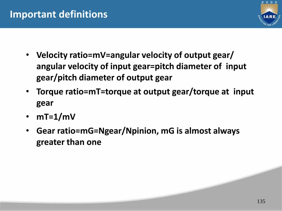
Important definitions
• Velocity ratio=mV=angular velocity of output gear/ angular velocity of input gear=pitch diameter of input gear/pitch diameter of output gear
• Torque ratio=mT=torque at output gear/torque at input gear
• mT=1/mV
• Gear ratio=mG=Ngear/Npinion, mG is almost always greater than one
135
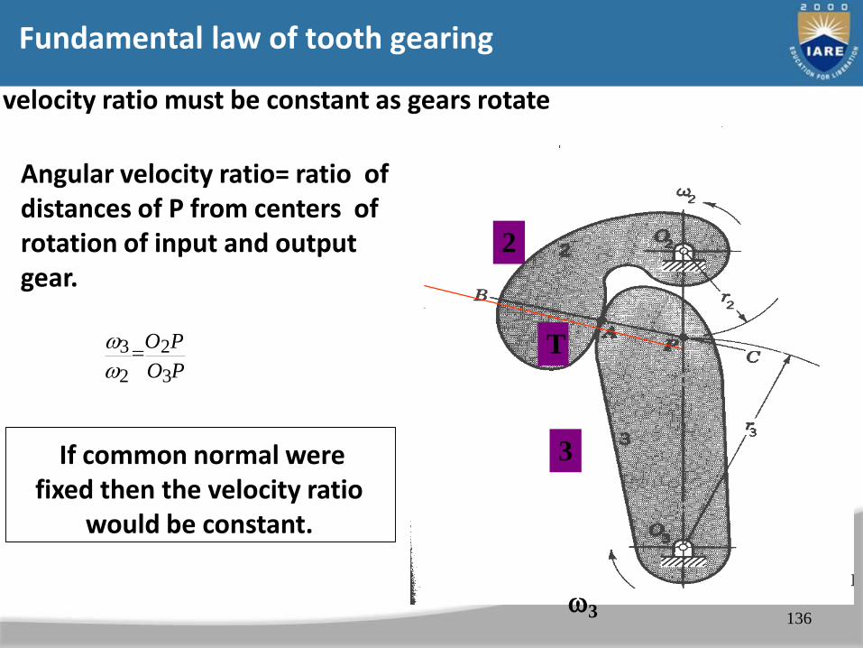
Fundamental law of tooth gearing
velocity ratio must be constant as gears rotate
136
Angular velocity ratio= ratio of distances of P from centers of rotation of input and output gear.
If common normal were fixed then the velocity ratio
would be constant.
2 O3P
3O2P
3
T
3
2
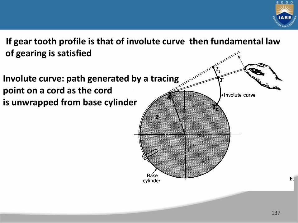
If gear tooth profile is that of involute curve then fundamental law of gearing is satisfied
137
Involute curve: path generated by a tracing point on a cord as the cordis unwrapped from base cylinder
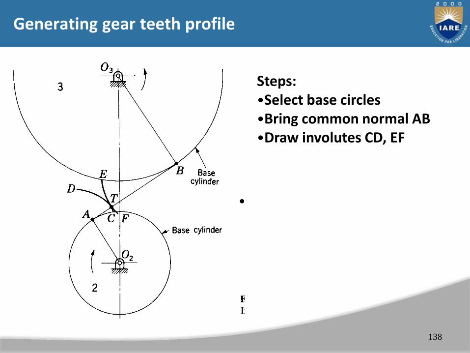
Generating gear teeth profile
138
Steps:•Select base circles•Bring common normal AB•Draw involutes CD, EF

Gear action
139
Angular velocity of Gear 3 / angular Velocity of gear 2 = O2P/O3P = constant
Fundamental law of gearing:
The common normal of the tooth profiles at all points within the mesh must always pass through a fixed point on the line of the centers called pitch point. Then the gearset’s velocity ratio will be constant through the mesh and be equal to the ratio of the gear radii.
140
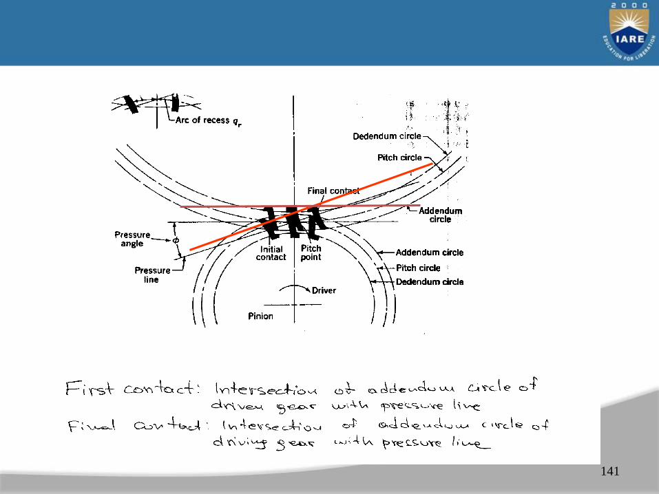
141

142
b3
Path of approach: BP=ua=[(r3+a)2-r 2]1/2-r3sin
b2
Path of recess: PC=ur=[(r2+a)2-r 2]1/2-r2sin
Final contact: CInitial contact: B

143
American Association of Gear Manufacturers (AGMA) (6.4)
Teeth of different gears have same profile as long as the angle of action and pitch is the same.
Can use same tools to cut different gears. Faster and cheaper product. Follow standards unless there is a very good reasons not to do so.
Stndard gears
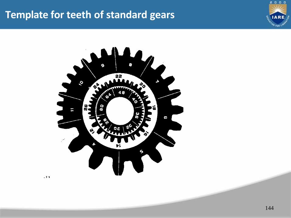
Template for teeth of standard gears
144

AGMA Specifications
• Diametral pitch, pd=1, 1.25, 1.5,…,120
• Addendum of pinion = addendum gear
• Observations
– The larger the pitch, the smaller the gear
– The larger the angle of action: the larger the difference between the base and pitch circles, the steeper the tooth profile, the smaller the transmitted force.
145
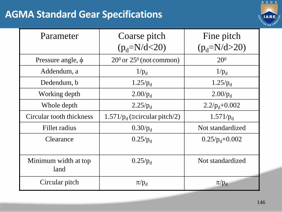
AGMA Standard Gear Specifications
Parameter Coarse pitch
(pd=N/d<20)
Fine pitch
(pd=N/d>20)
Pressure angle, 200 or 250 (not common) 200
Addendum, a 1/pd 1/pd
Dedendum, b 1.25/pd 1.25/pd
Working depth 2.00/pd 2.00/pd
Whole depth 2.25/pd 2.2/pd+0.002
Circular tooth thickness 1.571/pd (circular pitch/2) 1.571/pd
Fillet radius 0.30/pd Not standardized
Clearance 0.25/pd 0.25/pd+0.002
Minimum width at top
land
0.25/pd Not standardized
Circular pitch /pd /pd
146

147
1/pd
1.25/pd 1.571/pd
/pd
Min: 0.25/pd
0.25/pd
0.3/pd
d=N/pd
Planetary (or Epicyclic) Gears (10.4)
• Gears whose centers can move
• Used to achieve large speed reductions in compact space
• Can achieve different reduction ratios by holding different combinations of gears fixed
• Used in automatic transmissions of cars
148
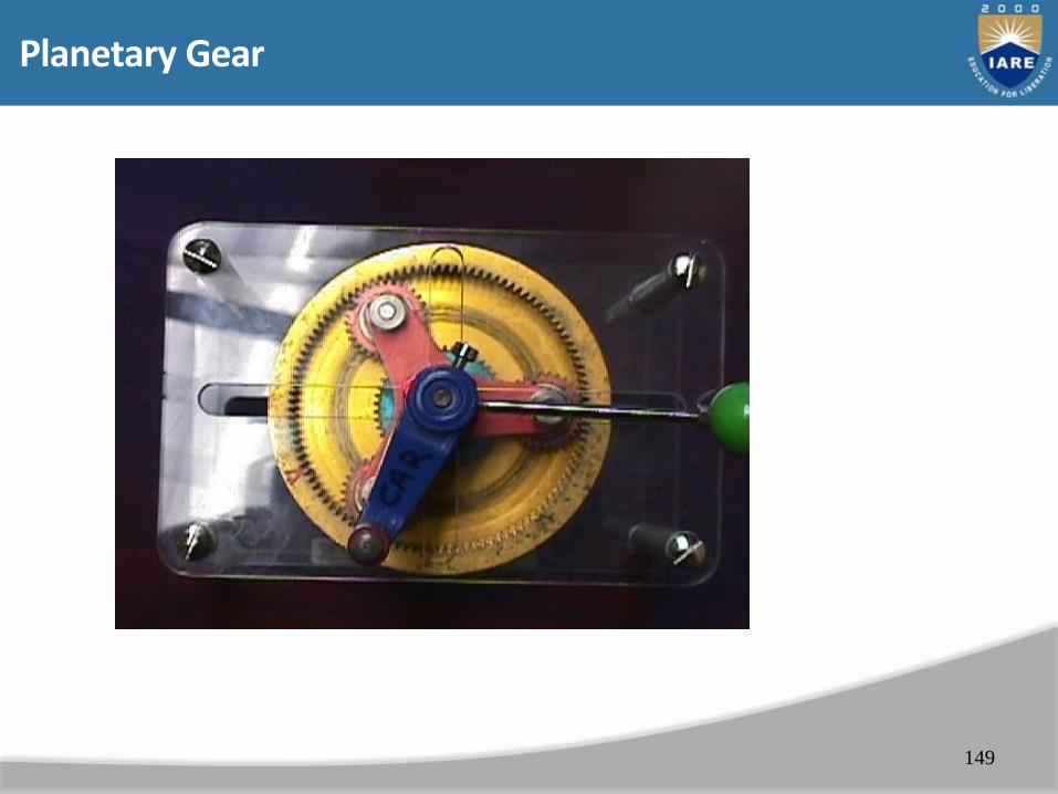
Planetary Gear
149
150
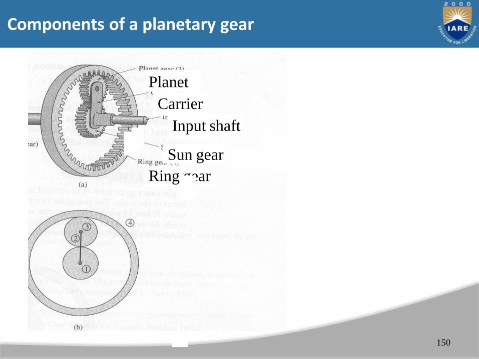
Planet
Carrier
Input shaft
Sun gear
Ring gear
Components of a planetary gear
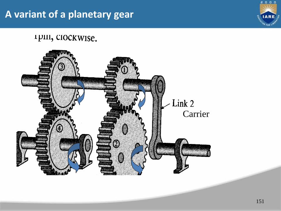
A variant of a planetary gear
151
Carrier

Velocity Analysis Of Planetary Gears (10.6, 10.7)
• Two degrees of freedom
• Given the velocities of two gears (e.g. sun and carrier) find velocities of other gears
• Approach
– Start from gear whose speed is given
– Use equation gear = car+ gear/car
153

154
Velocity analysis of planetary gear
Suspension
Objectives
• Identify parts of typical suspension systems
• Describe the function of each suspension systemcomponent
• Compare the various types of suspension systems
Introduction
• Vehicle chassis components– Frame
– Shocks and springs
– Steering parts
– Tires, brakes, and wheels
• Suspension system– Part of the chassis
– Many designs and many part names
• This chapter uses standard names
Suspension
• Supports the vehicle and cushions the ride
– Holds tire and wheel in correct position
• Sprung weight
– Weight supported by car springs
• Powertrain, body, and frame
• Anything carried by the weight of springs
• Unsprung weight
– Reducing unsprung weight increases control
• Tires, wheels, brakes, bearings, axels, and differential


Frame and Suspension Designs
• Cars are designed to be lightweight
– Improves fuel economy
• Newer cars have front-wheel drive
– Older cars had rear-wheel drive
• Front-wheel-drive cars
– Unibody design
• Sheet metal floor pan with small sections of frame at front and rear
– Made with sub-frame
• Includes engine, transaxle, and steering/suspension system
Springs
• Support the load of the car
– Absorb the up-and-down motion of wheels
• Coil spring: most common spring used in front and rear of passenger cars
– Variable rate spring: becomes stiffer as compressed
• Smoother ride over small bumps
• Torsion bar spring: straight rod that twists when working as a spring
– Mounted in the chassis
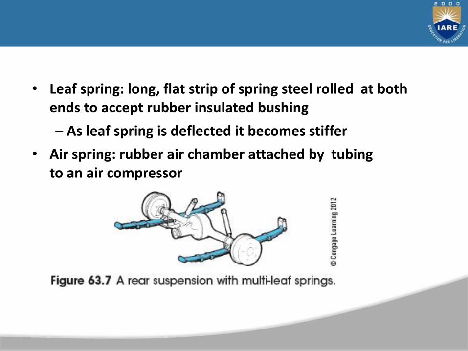
• Leaf spring: long, flat strip of spring steel rolled at both ends to accept rubber insulated bushing
– As leaf spring is deflected it becomes stiffer
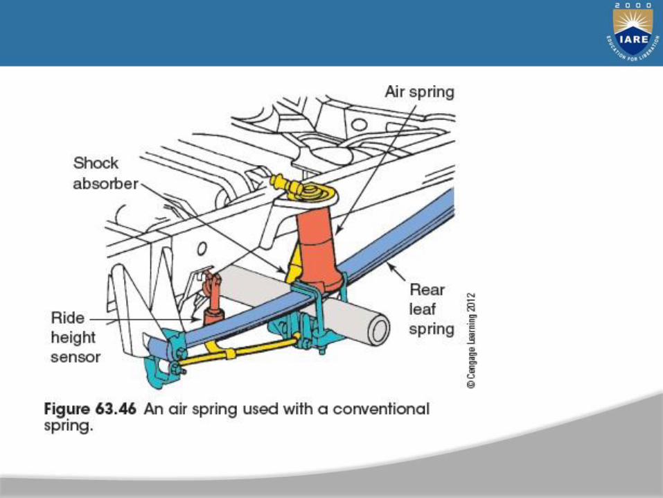
• Air spring: rubber air chamber attached by tubing to an air compressor

Suspension Construction
• Solid axel suspensions
– Wheel goes over a bump: other wheel also
affected
• Independent suspensions
– Wheel goes over a bump: only that wheel is affected
• Control arms
– Used on independent suspensions
– Allow springs to deflect

• Rubber bushings
– Keep suspension parts separate
• Ball joints
– Attach control arm to spindle
– Allows motion in two directions
Suspension Types
• Short and long arm suspension (SLA)
– Two unequal control arms which are not parallel
• Shorter control arm slants down toward outer end
• Double wishbone suspensions have improved directional stability
• Macpherson strut suspensions
– Coil spring and shock absorber incorporated into front suspension
• Single control arm on bottom
• Spindle attached to strut housing
• Strut bearing at top allows entire unit to rotate


High-Performance Suspensions
• Multilink suspension
– Independent suspension with more than two control arms
– Extra links keep wheel in more precise position during cornering and on bumps

Shock Absorbers
• One at each vehicle corner
– Dampen spring oscillations
• Convert spring energy into heat energy
• Poor shock absorbers
– Aggravate SUV rollovers
• Especially top-heavy vehicles

Hydraulic Shock Absorber Operation
• One end attached to suspension
– Other to car body or frame
• Force oil through passageways controlled by valves
– Generates hydraulic friction
– Converts motion energy into heat energy
• Two chambers with piston
– Forces fluid through valve from one chamber to the other
• Either twin-tube or monotube

Compression and Rebound Resistance
• Hydraulic shocks are sensitive to velocity
– The faster the piston moves, the higher resistance
• Compression damping
– Controls unsprung weight
• Works with spring to keep tire in contact with road surface
• Rebound damping
– Controls excess chassis motion as shock extends
Bump Stops and Limiters
• Shock absorber movement follows travel of vehicle suspension
– Damage results if shocks or struts reach extreme travel limit
• Shock absorber fluid aeration
– Aeration: hydraulic fluid mixes with air
– Shock must be installed in nearly vertical position

Gas Shocks
• Invented to control cavitation and hydraulic fluid foaming
– Pressurizing oil column in shock absorber keeps the bubbles in the solution
– Some gas shocks have pressurized gas-filled cell
• Takes place of free air in normal shock
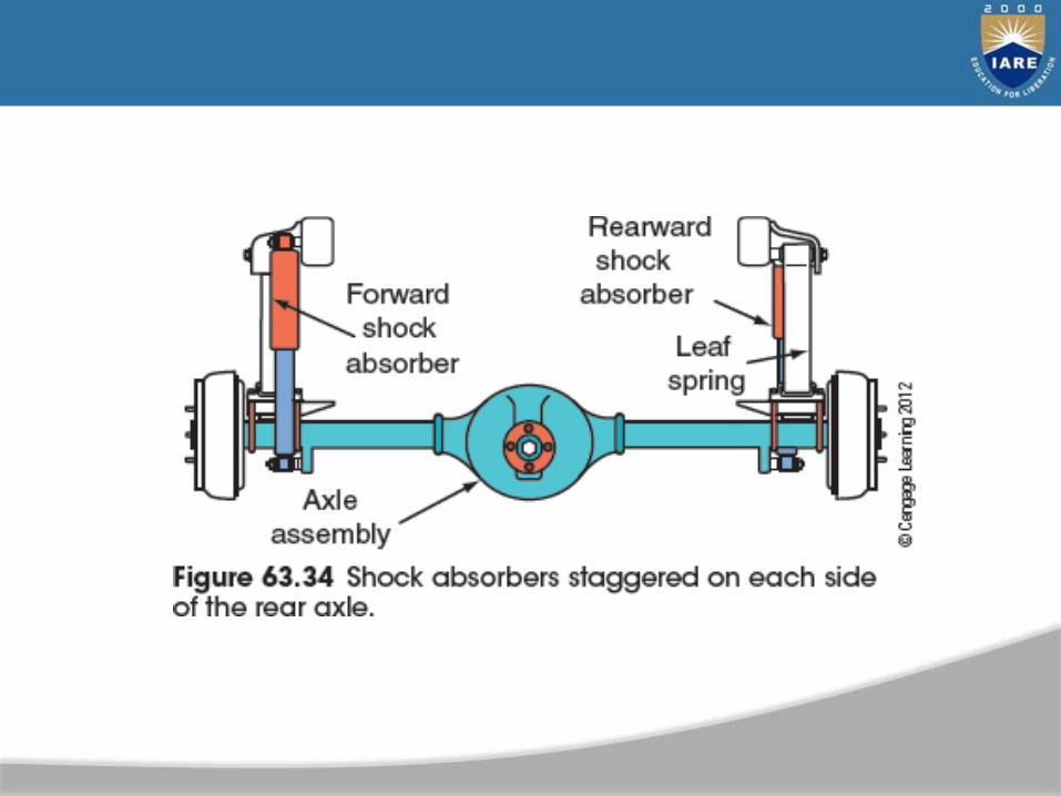
• Rear shock absorbers on RWD vehicles: mounted in two
ways
– Slanted inward toward rear at top
– One mounted in front of axle and the other behind

Air Shocks/Leveling Devices
• Shocks not designed to carry vehicle weight
• Some aftermarket devices use shock absorbers to correct vehicle height
– Air shocks
– Coil springs mounted on outside of shock body
• Disadvantages of leveling vehicle using shocks
– Shocks and shock mounts prone to breakage
• Coil spring shock prevents body roll
Other Front End Parts
• Other front end parts attached to suspension
– Help control the ride
• Stabilizers and strut rods
– Insulated from front suspension parts with rubber bushings

Stabilizer Bar
• Connects lower control arms on both sides of vehicle
– Reduces sway
– Functions as a spring when car leans to one side
– One wheel moves up: bar twists as it tries to move the other wheel along with it
• Ball joints
– Attach the control arm to spindle
– On suspensions with two control arms: ball joints function as load carrier or follower

Suspension Leveling Systems
• System types
– Passive systems: firm or soft ride
– Electronically controlled systems: computer reacts to signals from sensors at wheels
– Electronically controlled shock absorbers: variable
valving
– Magneto-rheological (MR) shock absorbers: use fluid that rapidly changes viscosity
– Active suspensions: double-acting hydraulic cylinder at each wheel to keep vehicle level
UNIT–IVBRAKING AND STEARING SYSTEMS
183
184
CLOs Course Learning Outcome
CLO10 Compare the types of braking system, working principles
CLO11 Explain the steering system and components of steeringsystem.
CLO12 Explain the steering mechanisms, techniques to improvebetter steering.
Objectives
• Describe the fundamentals of brake systems.
• Describe brake design requirements.
• List the six brake system categories.
• State the purpose of an antilock brake system.
• Discuss federal brake standards.
• By far most important mechanism on any vehicle
• Brakes on average vehicle applied 50,000 times a year
• Energy-absorbing mechanism converts vehicle movement into heat while stopping rotation of wheels
Fundamentals of Braking Systems
• Service brakes main driver-operated brakes of vehicle
• Also called base brakes or foundation brakes
• Brake System Parts
– To stop wheel, driver exerts force on brake pedal
– Force pressurizes brake fluid in master cylinder
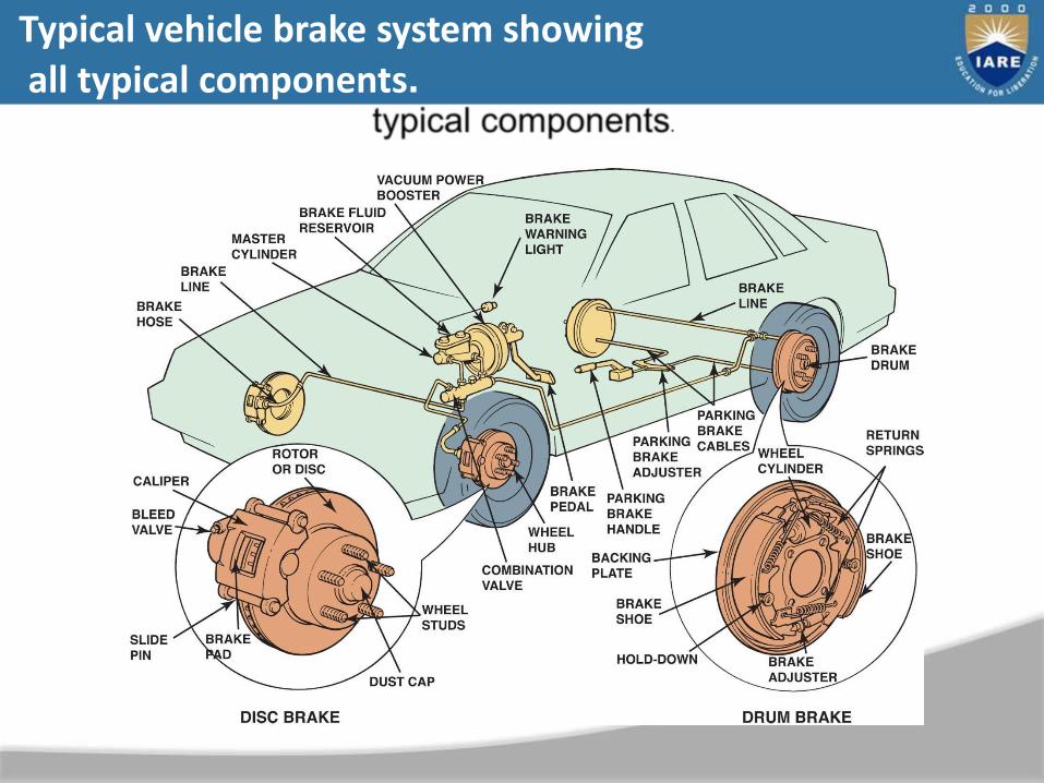
Typical vehicle brake system showing all typical components.

– Hydraulic pressure to each wheel cylinder or caliper forces friction materials against brake drum or rotor
– Friction causes rotating wheel to slow and eventually stop
• Brake System Parts
– Drum brakes
• Used on rear of many vehicles• When applied, brake shoes move outward
against rotating brake drum
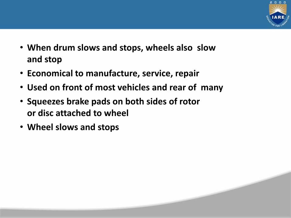
• When drum slows and stops, wheels also slow and stop
• Economical to manufacture, service, repair
• Used on front of most vehicles and rear of many
• Squeezes brake pads on both sides of rotoror disc attached to wheel
• Wheel slows and stops
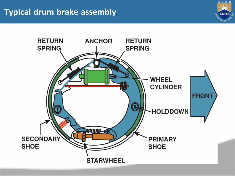
Typical drum brake assembly.
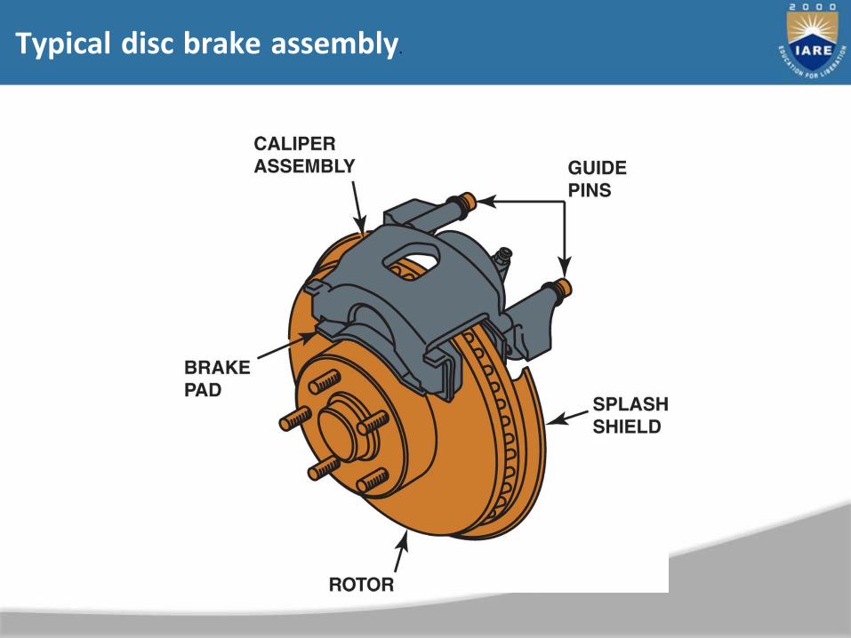
Typical disc brake assembly.

Brake design requirements
• Equal forces applid to left and right sides vehicle to
assure straight stops
• Hydraulic systems properly engineered and serviced to provide for changes as vehicle weight shifts forward during braking
• Valves must be used in hydraulic system to permit maximum braking forces but prevent undesirable wheel lockup

• Hydraulic system must use fluid that will not evaporate or freeze under extreme conditions
• Friction material (brake shoes or brake pads) must provide adequate friction between stationary and rotating parts; should be environmentally safe
• Design should secure brake lining solidly to prevent movement of friction material during braking
• Incorporate power assist unit; most commonly vacuum operated
• Components classified into six subsystems, depending on function
– Apply system
– Boost system
– Hydraulic system
– Wheel brakes
– Brake balance control system
– Brake warning lights
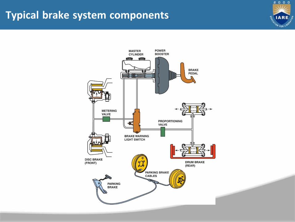
Typical brake system components.
• Purpose: to prevent wheels from locking during braking
• Friction between tire tread and road actually stops vehicle
• ABS does not mean that vehicle can stop quickly on all road surfaces
• ABS uses sensors at wheels to measure wheel speed
Antilock brake system overview
• If wheel rotating slower than others, indicates possiblelockup
• ABS hydraulic controller reduces pressure to wheelfor fraction of second
• Controller reapplies pressure fraction of second later
• If wheel starts to lock up, ABS system pulses brakes on and off to maintain directional stability with maximum braking force
Federal Brake Standards
• Federal Motor Vehicle Safety Standards (FMVSS)
• FMVSS Standard 135
– Ensure safe braking performance under normal and emergency conditions
– Establishes specific brake performance requirements
– Only four parts of brake system specifically regulated:
• Fluid reservoir and labeling
• Dashboard warning lights
• A method of automatic adjustment
• A mechanically engaging, friction-type parking brake system

• FMVSS 135 Brake Test
– Overall test procedure consists of up to 24 steps
– Burnish procedure
– Adhesion utilization (torque wheel method)
– Cold effectiveness
– High speed effectiveness
– Stops with the engine off

– Antilock functional failure
– Variable brake proportioning system
– Hydraulic circuit failure
– Brake power assist unit inoperative
– Parking brake
– Brake heat test
– Hot performance
Summary
• The brake system is by far most important mechanism on any vehicle.
• In the brake system design, equal force is applied to left and right sides vehicle to assure straight stops
• Brake systems have components classified into six
subsystems, depending on function.
Steering Systems
• Manual steering system – relies solely on the driver toprovide steering force
• Power assist – (power steering) – uses hydraulic orelectric power to help the driver apply steeringforce
• Both manual and power steering systems have common components.
• Input components:
– Steering wheel
– Steering column
– Steering shaft

Steering Column and Wheel

Steering Shaft
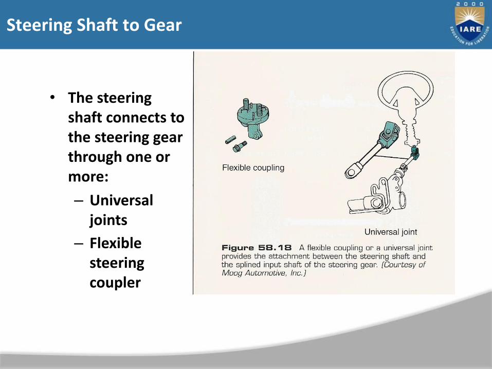
Steering Shaft to Gear
• The steering shaft connects to the steering gear through one or more:
– Universal joints
– Flexible steering coupler
Steering Systems
• The steering gear changes the rotary motion of the wheel into linear motion of the steering linkage.
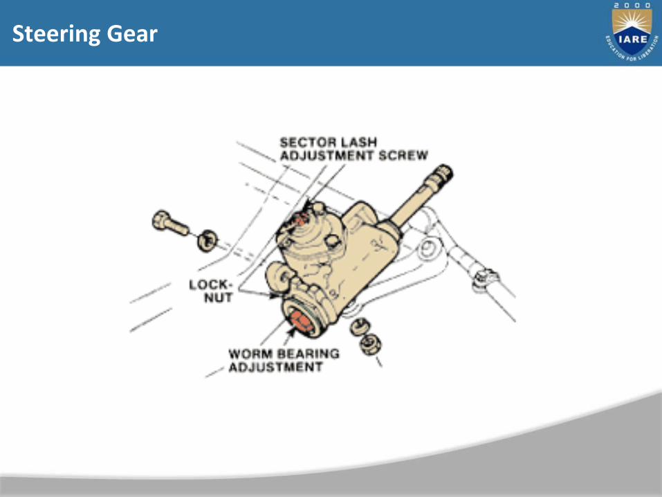
Steering Gear

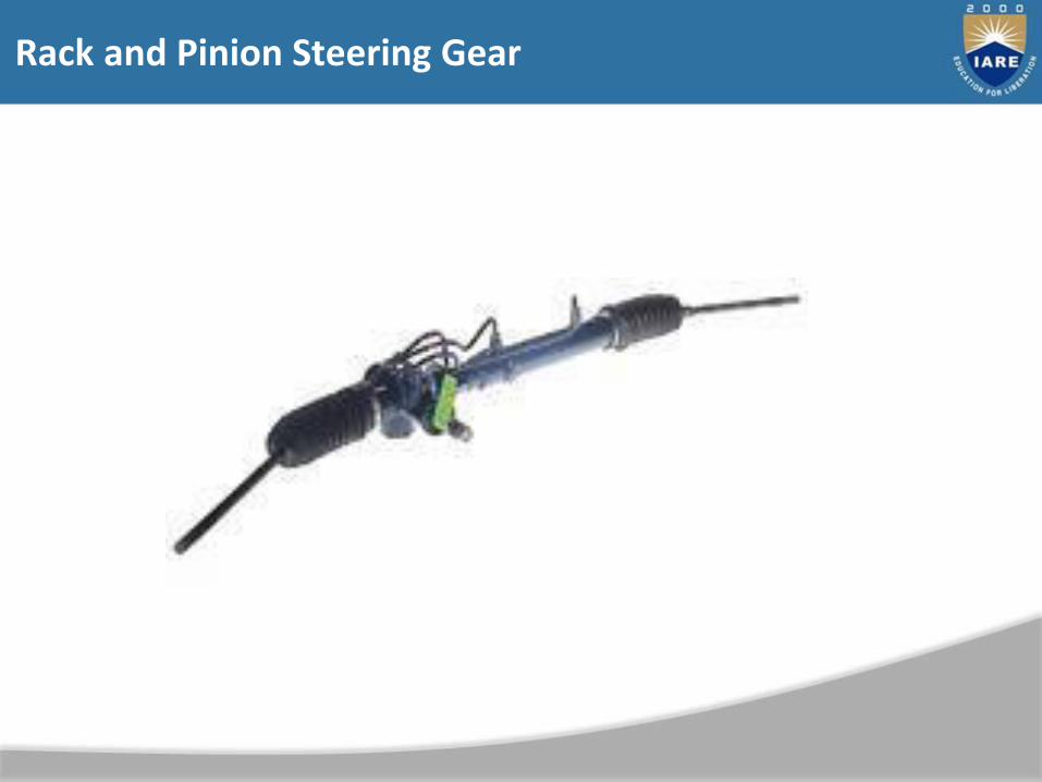
Rack and Pinion Steering Gear

Steering Linkage
• Connects the linear motion of the steering gear to the steering arms.
• Parallelogram type linkage (typical) –
– Pitman arm
– Idler arm
– Center link
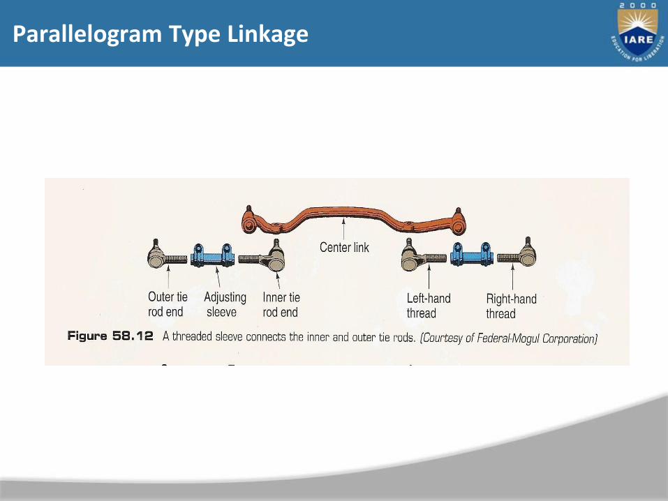
– Inner tie rod
– Outer tie rod
– Tie rod adjustment sleeve
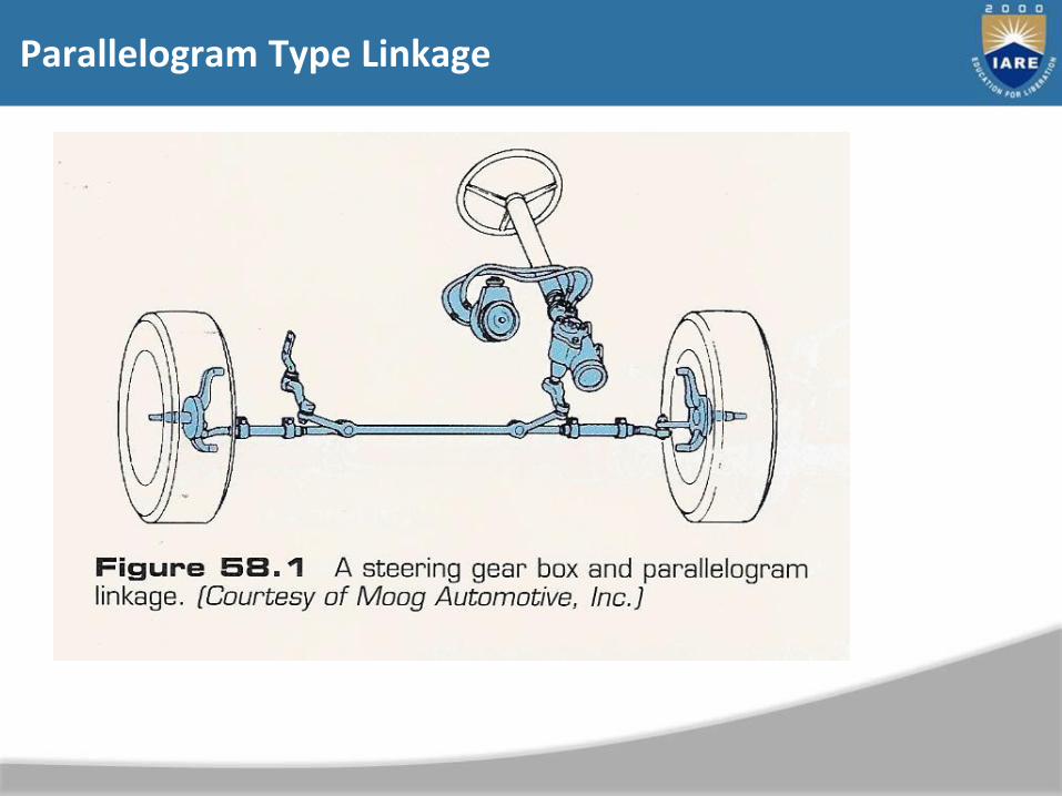
Parallelogram Type Linkage
Parallelogram Type Linkage
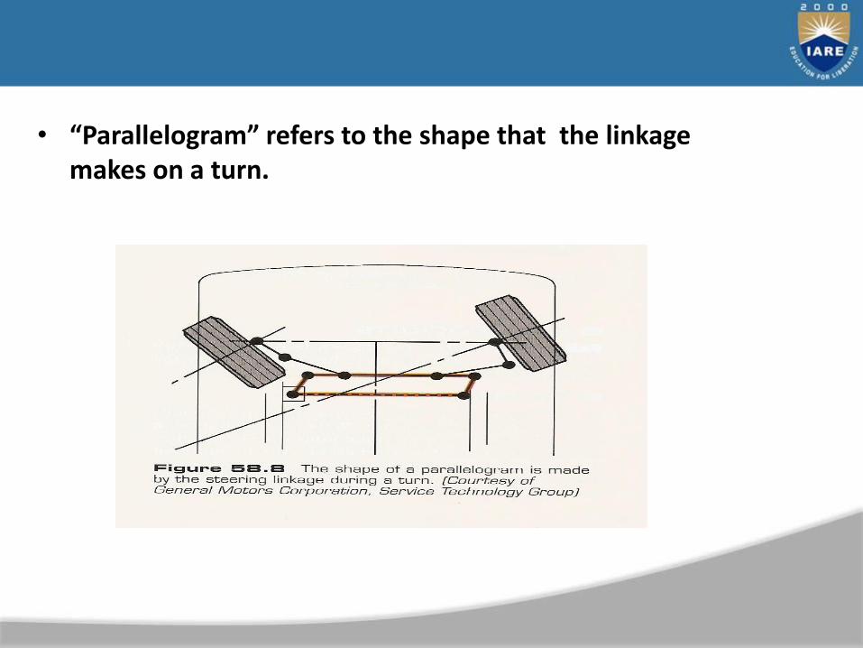
• “Parallelogram” refers to the shape that the linkage makes on a turn.
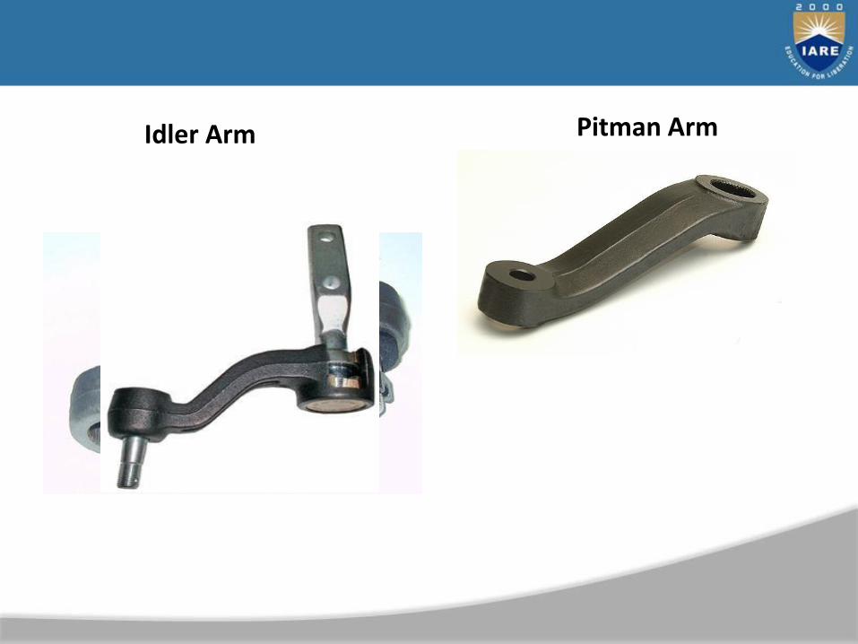
Idler Arm Pitman Arm

Steering Linkage
• Rack and Pinion linkage
– Inner tie rod
– Outer tie rod

Ball Sockets
• Allow suspension travel without binding
– Tie rods – located at the steering knuckle.
• Also at the center link on parallelogram type.
– Ball joints – located at the top and bottom of the knuckle. Allows for movement between the knuckle and control arm(s).
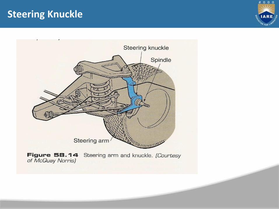
Steering Knuckle
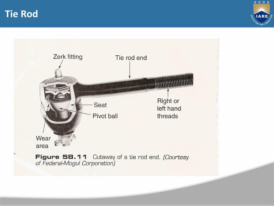
Tie Rod
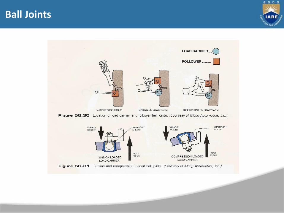
Ball Joints
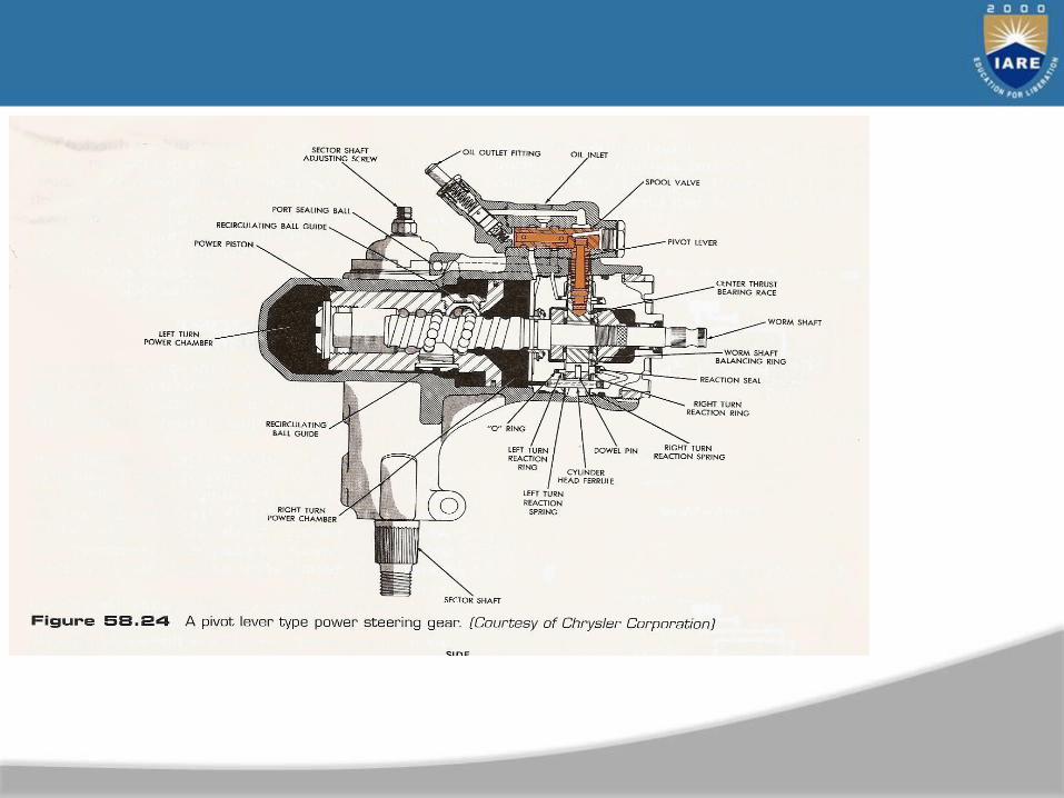
Recirculating-Ball Steering Gear
• Primarily used on trucks, vans and larger vehicles.
• Also used on most passenger vehicles prior to 1980.
• Used in conjunction with a parallelogram-type linkage
system.

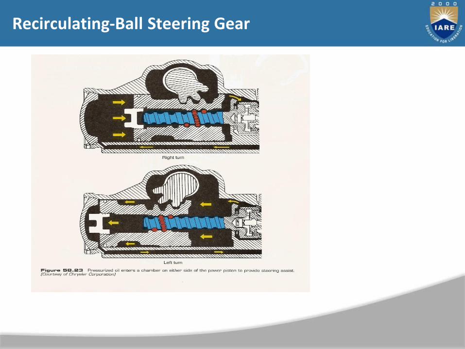
Recirculating-Ball Steering Gear
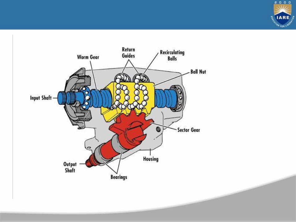
• Uses a series of recirculating balls on a worm shaft to transfer steering-wheel movement to tire and wheel movement.
• The steel balls within the gear box housing constantly
recirculate within the guide paths.
• They move from one end of the ball nut through return
guides to reenter the ball nut at the opposite end.
• The balls provide low-friction contact points between the worm gear and the internal grooves of the ball nut.
Recirculating-Ball Steering Gear
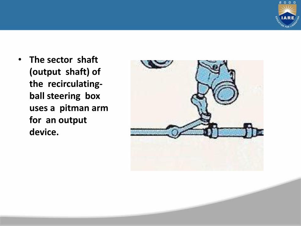
• The sector shaft (output shaft) of the recirculating-ball steering box uses a pitman arm for an output device.
Recirculating-Ball Steering Gear
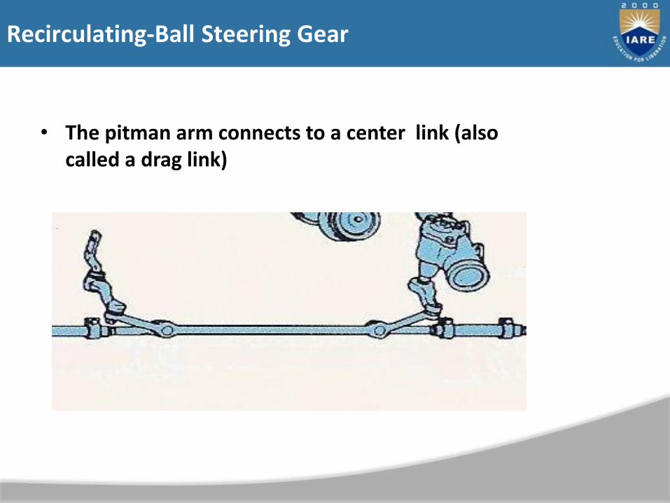
• The pitman arm connects to a center link (also called a drag link)

• The other end of the center link is attached to a idler arm

• The pitman arm and idler arm act as the center links pivot points.
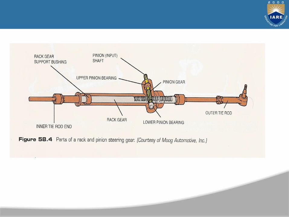
Rack and Pinion Systems
• Most passenger vehicles today use rack and pinion steering systems.
• Generally contained in one complete housing.
• The steering shaft connects to a pinion shaft through a universal joint or coupler.
• The pinion gear meshes with a a rack of gear teeth.
• Fewer parts
• Lighter
• Modular
• Saves space
• Generally not as strong as a recirculating-ball type system
– Suitable for today’s lighter cars.
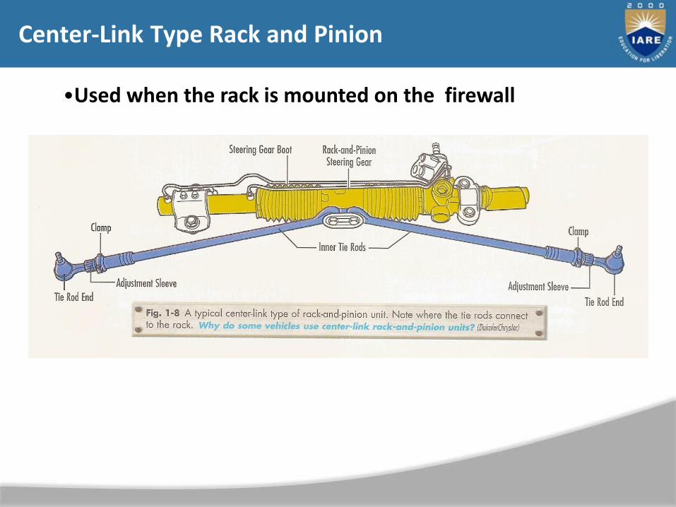
Center-Link Type Rack and Pinion
•Used when the rack is mounted on the firewall

• Why are some vehicles still equipped with parallelogram type steering systems?
• Why do most vehicles use a rack and pinion design?
• Why is a parallelogram system called a parallelogram system?
Automotive Steering Systems Basic

UNIT–VEMISSIONS FROM AUTOMOBILES
241
242
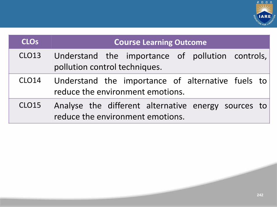
CLOs Course Learning Outcome
CLO13 Understand the importance of pollution controls,pollution control techniques.
CLO14 Understand the importance of alternative fuels toreduce the environment emotions.
CLO15 Analyse the different alternative energy sources toreduce the environment emotions.
Objectives
• Describe the different types of air pollution caused by motor vehicles
• Explain the fundamentals of the major emission control systems
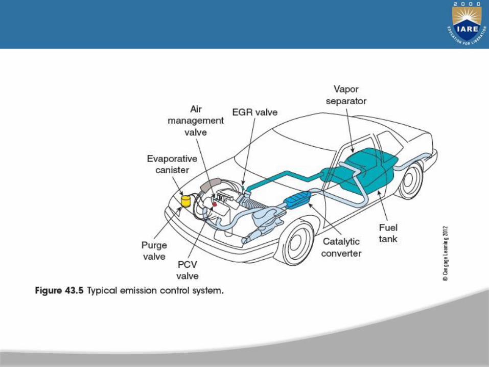
• Label the parts of emission control systems
• Explain the operation of electronically controlled emission systems

Introduction
• Emission controls
– Began to be included on cars in the 1960s
– Complicated specialty area
– Most states: emission specialists are required to be licensed to perform repairs

• Photochemical smog
– Hydrocarbons and oxides of nitrogen react with sunlight
– Warm air inversion layer traps smog
• Pollution laws
– Administered by the EPA
– Vehicles manufactured today produce less than 5% of the air pollution of 1960s models
Air Pollution
Automotive Emissions
• Sources of emissions
– Exhaust pipe, crank-case, and vapors
• Hydrocarbon sources
– Blowby gases
– Skin effect
– Raw gas in exhaust
– Insufficient compression
– Inadequate ignition spark
Automotive Emissions (cont'd.)
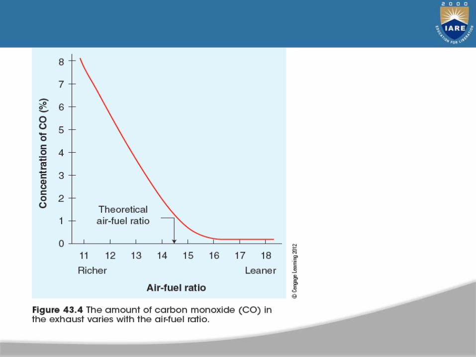
• Carbon monoxide emissions– Result when gasoline not completely burned
• Oxides of nitrogen
– Produced when combustion temperatures are too high
• Particulates– Are airborne microscopic particles
• Carbon dioxide and oxygen
– Used to diagnose combustion problems– Carbon dioxide is a greenhouse gas
Pollution Control
• Early 1960s: California led emission control legislation
– 1961: crankcase emission system required on all new cars in California
• 1963: crankcase emission system required on all new cars
in U.S.
• 1966: exhaust emission systems required on new cars in
California
• 1970: U.S. Congress passed Clean Air Act

Automobile Emission Control Systems
• Lower exhaust emissions
– Engine design
– Fuel and ignition system controls
– Devices designed to control emissions
• Computers manage emission devices
– Engine load
– Engine temperature
– O2 sensor
Crankcase Ventilation
• PCV system
– Reintroduces blowby gases into combustion chambers
• Benefits of PCV system
– Prevents emissions of HCs
– Reduces sludge
– Reduces oil leakage
• Closed ventilation system
– Filtered intake air is supplied through hose from air cleaner
Air Injection System
• Feeds hot gases to keep them burning
– Air is provided by belt-driven air pump, electric
motor-driven pump, or non-pump pulse air system
• Functions
– Provides low-pressure air supply
– Provides air to catalytic converter
• Air injection system uses an air pump, control valves, and
lines to manifolds
– Some vehicles have electric air pumps
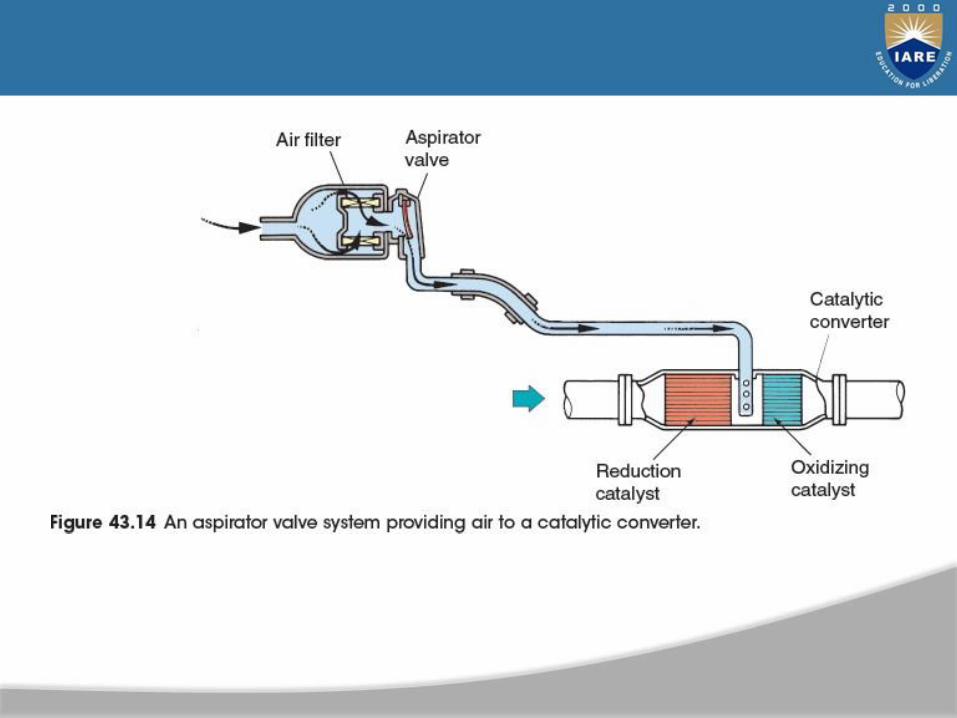
Aspirator Valve or Pulse Air System
• Momentary low-pressure condition (pulse) occurs at end of exhaust stroke
– Aspirator valve or pulse air system uses pulses to blow fresh air into exhaust
• Not efficient at high speeds
– One-way check valve (i.e., aspirator valve) allows fresh air from cleaner
• Flows when vacuum created by exhaust pulse
• Closes when exhaust pressure builds
Exhaust Gas Recirculation
• Lean air-fuel mixtures and higher operating temperatures raise NOX
– Exhaust gas recirculation (EGR) system allows exhaust gas into air-fuel mixture
• Diluting air-fuel mixture with exhaust gas lowerscombustion temperature by 300°F
– EGR improves fuel economy
• Early EGR systems were often disabled to improve fuel economy
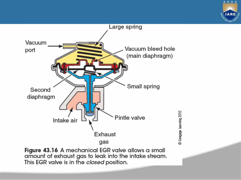
EGR System Operation
• Simple EGR system has an EGR valve operated by engine
vacuum
– Located on intake manifold
• Little NOX is formed at idle
– EGR valve is closed at these times
• Exhaust backpressure is a good indicator of engine
load
– More EGR flow needed under load
• Thermal vacuum valve (TVV)
– Prevents vacuum operation before engine is warm
Computer-Controlled EGR Systems
• Today’s cars have computer-controlled EGR systems
– EGR valve is controlled by input signals of engine temperature and load
• Vehicle speed signal or PRNDL switch
– Position sensors on EGR valves: included in late-model engines
– Digital EGR valves: EGR flow regulated by computer using a series of solenoids
– Linear EGR valves: include a stepper motor
Catalytic Converter
• Catalyst
– Causes chemical reaction without changing itself
• Chemical reaction only occurs in presence of catalyst or occurs faster because of one
• Catalytic converters
– Must be hot to operate
– Monolithic catalyst has thing coating of platinum applied to ceramic coated with alumina
– Late-model vehicles have pre-catalysis which
begin operating earlier
Types of Catalytic Converters
• Two-way catalyst; changes HC and CO into CO2 and H2O
• Three-way catalytic converter: used with oxygen sensor
– Reduces NOX and oxidizes HC and CO
– Single or dual bed design
• Dual bed catalytic converters include air switching valve and diverter
– Use rhodium as a catalyst
– Needs heat and regulated air-fuel mixture
Evaporative Controls
• Control emission of gasoline vapors from tank
– Activated charcoal store gasoline vapors until they are
drawn into the engine and burned
– Emission of fuel vapors is controlled by sealing the fuel system
• Gasoline tanks allow for fuel expansion of 10%
– Expansion dome and liquid/vapor separator
– Expansion tank
– Filler neck design
• Gas caps sealed or have pressure vacuum valve
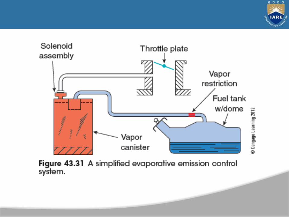
Other Parts of the Fuel Tank System
• Include:
– Liquid vapor separator keeps liquid fuel frombeing drawn into charcoal canister
– Charcoal canister stores vapors from fuel tank
– Thermostatic air cleaner (TAC) maintainconsistent air-fuel mixture
– Manifold heat control valves were used to reduceexhaust emissions and improve drivability duringengine warmup

On-Board Diagnostics
• 1988: on-board diagnostics regulations became law
– Require computer to monitor engine’s O2 sensor, EGR valve, and charcoal canister purge solenoid
– Malfunction indicator light was also required
• Names of emission parts and connections for test equipment were standardized
– Part of the OBD II regulations
Engine Emission Modifications
• Common modifications
– As little as possible exposed surface area on the combustion chamber and top of piston
– Engines run with higher cooling system temperatures
– Advancing ignition timing can increase fuel economy
– Changing cam design specifications results in different emissions
– Domestic diesel light trucks and vans are now using urea selective catalyst reduction
Auto Mobile Fuels
• Explain the refining process of petroleum- based fuels.
• Describe the combustion process of an internal combustion engine.
• Describe the four performance characteristics of gasoline.

• Explain how Reid vapor pressure is measured.
• Explain the difference between winter and summer blend gasoline.
• Explain how octane ratings are determined.
Objectives (3 of 5)
• Explain what the octane rating represents.
• Describe the common methods of
determining the octane number.
• Determine the differences between regular and
premium gasoline.
• Describe the various types of gasoline and additives.

• Explain the purpose of oxygenated fuels.
• List and describe the common oxygenated fuel blends.
• Describe the different alternative fuels.
• Describe the properties of diesel fuel.
• Explain the differences between diesel fuel grades.
• Explain the cetane rating of diesel fuel.
• Describe how cetane ratings affect power output.
• Explain what API gravity is and how it affects power
output.
Introduction
• This chapter describes the composition and qualities of:
– Gasoline
– Diesel fuel
– Alternative fuels

Gasoline Composition (1 of 2)
• Crude oil is a combination of light and heavy hydrocarbon compounds.
• Refining crude yields oils, greases, gasoline, diesel fuel, and other compounds.
Gasoline Composition (2 of 2)
• Gasoline components are custom blended from refined crude oil for proper:
– Octane
– Emissions
– Storage life
– Volatility
Combustion Chemistry
• Combustion is the process of burning air and hydrocarbons (HC) in the engine.
– HC+O2+N2+spark = H2O+CO2+CO+HC+NOx+other chemicals
Stoichiometric
• If combustion were complete, then all of the fuel (HC) would be combined with the available O2.
• This mixture of 14.7 parts air to 1 part of oxygen is called the stoichiometric ratio, or stoichiometry.
Gasoline Characteristics
• Important characteristics we will consider:
– Volatility
– Sulfur content
– Additives
– Octane rating
Volatility
• Volatility is the measure of a fuel’s ability to vaporize.
• Only vaporized fuel supports complete combustion.
• Liquid fuel in the combustion chamber dilutes engine oil and prevents lubrication.
Low Volatility Problems
• A fuel with low volatility causes:
– Hard cold starts
– Poor cold driveability
– Increased plug and combustion chamber deposits
High Volatility Problems
• High evaporative emissions
• Poor hot driveability
• Poor fuel economy
Winter Blend
• In the winter (in cold areas of the country), fuel must be more volatile in order to provide good cold starts and driveability.
• This fuel is specially blended for winter use only, and would be too volatile for summer.
Summer Blend
• Fuel used in the summer must be less volatile to preventhigh volatility problems because of higher temperatures.
• Fuel is also blended for the altitude where it is used.

Reid Vapor Pressure
• A measure of a fuels volatility is called Reid vapor pressure.
Sulfur Content
• Sulfur is contained in crude oil and some remains in the gasoline.
• Too much sulfur causes corrosion in the engine and exhaust system, and a rotten egg smell.
• Sulfur is limited to .01% by regulation.
Fuel Additives (1 of 2)
• Tetraethyl lead was added at one time to improve octane ratings of fuel.
• Unleaded fuel is required by the catalytic converter, so leaded fuel is no longer available.
Fuel Additives (2 of 2)
• Detergents– Used to keep fuel injectors clean
• Anti-icing– Prevents gas line freeze up
• Metal deactivators and rust inhibitors– Prevent reactions between fuel system metals and fuel
• Gum or oxidation inhibitors
– Helps prevent formation of gum when gasoline is stored.
Octane Ratings (1 of 2)
• A higher compression ratio makes an engine more
efficient.
• A higher compression ratio also makes an engine more
likely to experience detonation.
• Octane rating is a measure of the fuel’s ability to resist
detonation.
Octane Ratings (2 of 2)
• A test engine is used to determine the octane of a fuel sample by comparing its anti-knock capability against a test fuel mixture.
Octane
• Fuel burns within a few milliseconds, but is considered a controlled burn, not an explosion.
• The flame front moves at about 50 to 250 meters per second.
Detonation (1 of 2)
• When detonation is occurring, the flame front moves at about the speed of sound.
• When detonation occurs, the pressure inside the engine builds too quickly, which can damage the engine, and produce spark knock.
Detonation (2 of 2)
• The spark-knock you hear when detonation is occurring isthe result of the engine structure ringing due to thepressure spike.
• Engine design and computer-controlled timing, along with
fuel of the proper octane all help control detonation.
Regular and Premium Fuel
• Regular fuel = 87 octane
• Mid-grade = 89 octane
• Premium = 93 octane
• High compression engines require higher octane fuel.
• Engines designed for regular fuel do not benefit from premium.
Octane Improvers
• Since lead can no longer be used to improve octane,several other compounds have been utilized.
– Aromatic hydrocarbons
– Ethanol, methanol, tertiary butyl alcohol (TBA)
– Metallic compounds such as MMT

Oxygenated Fuels
• Oxygenated fuels reduce the amount of carbon monoxide emission by adding compounds such as alcohols and ethers that have oxygen in their molecular structure.
• The molecular oxygen is released during burning and produces a leaner air fuel mixture.
Methanol
• Methanol is made from coal, natural gas, oil shale, wood, or garbage.
• It requires a special fuel system because methanol is so corrosive.
• Methanol-gasoline mixes do not have as much energy as gasoline alone.
Ethanol
• It is the most common alcohol/gasoline mixture.
• It increases the octane level of fuel.
• Vehicles using ethanol mixes need more frequent fuel filter changes.
• Gasoline/ethanol mix absorbs water.
Advantages of Alcohol Additives
• Absorbs water in fuel tank
• Cleans the fuel system
• Reduces CO emission
• Increases fuel octane by three points
Disadvantages of Alcohol Additives
• Can clog fuel filters due to cleaning action
• Raises the volatility of fuel
• Lowers miles per gallon by 2-3%
• Absorbs water then separates from gasoline in cold weather
• Alcohol does not vaporize as easily as gasoline
Reformulated Gas
• Mandated by the EPA for ozone non-
attainment areas
• Compared to regular gasoline RPG:
– Has lower levels of compounds that contribute to air pollution
– Has a lower vapor pressure
– Contains oxygenates
Alternative Fuels
• Tighter EPA emission regulations have lead to the search for viable alternative fuels.
Liquid Petroleum Gas
• Mostly propane with a small amount of butane
• Burns very clean
• Has a higher octane rating than gasoline
Natural Gas
• One of the cleanest burning fuels available
• Lighter than air so it dissipates quickly
• Reduces maintenance on vehicles because it burns so cleanly
• Lack of infrastructure to refuel biggest disadvantage
Hydrogen
• Produces only water and carbon dioxide when burned
• One of the most abundant elements in the universe
• Octane rating of over 130
• Lack of infrastructure for refueling

E-85
• A mixture of 85% ethanol and 15% unleaded fuel
• Has an octane rating of 100
• Requires a flex-fuel option equipped vehicle to use
Diesel Fuel
• Diesel engines use the heat of compression to ignite the fuel.
• Diesel fuel has its own set of standards, just like gasoline.
Density
• Power output of a diesel engine is related to fuel density.
– More dense fuel has a higher power output.
– Less dense fuels get fewer miles per gallon.

Viscosity
• Diesel fuel must be able to flow through the fuel system and therefore have low viscosity.
• Viscosity also affects injector spray pattern.
• Viscosity must be high enough to lubricate fuel injectors, but not produce large droplets of fuel that are hard to burn.
Cloud Point and Pour Point
• As diesel fuel gets colder, these points are eventually reached:
– Cloud point is when paraffin starts to form in the fuel which blocks fuel flow.
– Pour point is when the fuel solidifies.
• The higher the fuel quality, the lower the temperature for both “points.”
Volatility
• Even though diesel fuel is not as volatile as gasoline, volatility is still important.
– Low volatility fuels leave too much carbon residue behind for automotive diesels.

Cetane Rating
• Cetane is the measure of diesel fuel ignition quality.
• A sample of fuel is assigned a cetane rating based on its ignition lag time.
• The shorter the lag time the higher the cetane rating.

Sulfur Content
• Limited to .05% sulfur by law.
• Excessive sulfur content causes sulfuric acid to form during combustion which damages engine components.

Diesel Fuel Grades
• Minimum quality standards for diesel fuel grades have been set.
Grade 1
• Low-temperature fuel
• Has highest volatility
• Lowest pour and cloud point
Grade 2
• Higher volatility, pour point, and cloud point than grade 1
• Most commonly used diesel fuel grade
• In cold climates, diesel 1 and 2 mixed to provide easier
starting
• Fuel mileage drops due to the addition of diesel 1
Grade 4
• Not an automotive fuel
• For low speed engines under a constant load
Cleanliness
• Diesel fuel must be free of water and debris becausediesel fuel lubricates and cools fuel system components.