automotive energy efficiency improvement applying …
TRANSCRIPT

AUTOMOTIVE ENERGY EFFICIENCY IMPROVEMENT APPLYING START & STOP
SYSTEM AND ALTERNATOR OPERATION STRATEGIES
Luis Gustavo de C. Monteiro1.2, Fabrício J. P. Pujatti1, John M. S. Sousa1, Luis Carlos M.
Sales 2.3 e João P. Rodrigues2
1Universidade Federal de Minas Gerais (UFMG)
2Fiat Chrysler Automobiles (FCA) 3Pontifícia Universidade Católica de Minas Gerais (PUC-MG)
E-mails: [email protected], [email protected],
[email protected], [email protected], [email protected]
ABSTRACT
With the formidable growth of the automotive industry, also came the concern with the rise of
greenhouse gas emissions and the importance of this sector to develop innovative
technologies to increase energy efficiency, reducing fuel consumption and consequently
mitigating CO2 emissions. This research aimed at the experimental analysis of the energy
consumption and CO2 reduction comparison applying Stop & Start system and alternator
operations strategies. One of these alternator operational strategies is based on its mechanical
and electrical coupling and decoupling due to a pulley integrated to an electromagnetic clutch
in certain predetermined circumstances. This operation was elaborated from the conventional
strategy that contemplates only the electrical decoupling, known as "smart alternator". The
tests were performed on a vehicle in the urban and highway cycles (FTP75 + HW) in order to
evaluate its operational characteristics, as well as obtaining the energy consumption of each
configuration. Compared to the baseline configuration, the results presented energy
consumption reductions of 2.38% and 3.56%, using separately the Start & Stop system and
alternator operating strategies, respectively, and reduction of 4.91% when combined.
INTRODUCTION
Global concern about rising global average temperatures has led several countries to adopt
measures that can minimize the effects of pollution on future generations. To do so,
legislations have been created so that, mainly, the industries have parameters to be followed
and can always work seeking to reach the governmental targets.
In Brazil, this scenario is not different. During the period of 2013 to 2017 the program of
Incentive to Technological Innovation and Chain of Auto-vehicles Production, denominated
INOVAR-AUTO was in force. When finalized, there was already a proposal for its successor,
what would become ROTA 2030, which like INOVAR-AUTO, are measures put by the
government so the companies in the automotive industry follow and fulfill minimum
requirements of energy efficiency and emission of greenhouse gases (GHG), and those that
exceed those requirements will have fiscal incentives. In order to achieve ROTA 2030 targets,

it is necessary to invest heavily in research and development in the automotive sector, thus
new innovative technologies may be installed in vehicles within the next few years.
Given the need to apply new technologies to improve energy efficiency in light-duty internal
combustion vehicles, the objective of this article is the experimental comparative analysis of
isolated and combined Stop & Start and alternator technologies with mechanical and electrical
decoupling strategies. [1] [2]
1. LITERATURE REVIEW
Among the trends to improve automotive energy efficiency, the Start & Stop (S&S) system
has gained prominence and increased application by car manufacturers around the world. This
system consists of automatic shutdown of the internal combustion engine of the vehicle at
zero speed (stops on traffic signals, intersections and / or slow traffic). The vehicle's engine is
then turned back on when the driver intends to retake the movement (driving the clutch pedal
in manual vehicles or disengaging the brake pedal in automatic vehicles).
For the Start & Stop operation system, automotive components with differentials are required
to ensure the durability of the vehicle subsystems throughout the car's operating cycle.
Amongst the components, there is a need for more robust starting motors and special batteries
to withstand sequential loading and unloading cycles, since at each successive start of the
engine (system characteristics), energy consumption is demanded from the vehicle battery.
The classical energy balance of internal combustion engines has shown that friction and
auxiliary accessories can consume a large part of thermal energy [3].
Among the auxiliaries, the alternator significantly influences the increase in the energy
consumption of the internal combustion engine, which can be attributed to this component
from 4 to 6%. In this way, improving the efficiency of the alternator reduces energy loss.
Thus, high efficiency alternators can reduce energy or fuel consumption from 0.5% to 2.0%.
[4]
In addition to the evolution of the alternators in terms of efficiency strategies were also
developed for the electronic management of electric power generation. In the electric power
management of the vehicle, the IBS (Intelligent Battery Sensor) technology has the main
function of monitoring the battery parameters, such as current, voltage and temperature of the
battery. From this data it is possible to estimate other important parameters as the SOC (State
of Charge). [5]
The IBS is an electronic module integrated with the negative battery terminal. The collected
and calculated information is sent by the local interconnection network (LIN), and it is used
by the vehicle electronic control unit (ECU). [6]
The IBS is a relevant sensor, as it continuously performs the analysis and supply of the main
parameters such as the battery state of charge (SOC) and the battery degradation (SOH) that
are inputs for vehicular control systems. The “smart alternator” technology is the result of the
high efficiency alternator combined with LIN and IBS. The alternator coupling and
uncoupling to the crankshaft pulley are subject to the estimated battery parameters by the IBS.
Another system that directly depends on the parameters determined by the IBS, mainly the

state of charge of the battery (SOC), is the "Start & Stop" (S & S). If there are no safe
conditions for shutting down and starting the internal combustion engine, the "Start & Stop"
strategy is inhibited.
Another strategy associated with the alternator is its mechanical and electrical decoupling that
is achieved with the patented prototype alternator [1] [2] used in this study, representing an
attractive solution to increase the vehicular efficiency energy. From this strategy, complete
unloading of the crankshaft shaft is allowed. For this to occur, this alternator has an
electromagnetic clutch coupled to its pulley. The strategy is to decouple the alternator from
the crankshaft when the battery is sufficiently charged to support the operation of the vehicle.
In suitable conditions, in terms of electric power generation, the alternator is coupled. [3].
2. METHODOLOGY
2.1. Experimental Apparatus
In this study, a vehicle with the Start & Stop system was used, in this way, with each
condition characterized as idling, its internal combustion engine was shut down.
For the Start & Stop system works properly, a number of parameters are controlled so
the vehicle operates on a regular basis and maintains occupant safety throughout the
operation.
In zero-speed vehicle condition, the S & S acts primarily if the gear is in neutral (for
"manual vehicles") or with the guarantee that the brake will have a certain vacuum
pressure for ("automatic vehicles"). The Start & Stop system depends, in addition to
the idling condition, on the engine temperature, which can be observed and evaluated
through the water temperature. In other words, in the first phase of urban cycle, the
Stop & Start function will not turn off the engine until the water temperature reaches
the minimum required. In addition, the driver's door and bonnet must be closed; the
driver's seat belt must be buckled; the vehicle must not be in an adaptive fuel
condition and, finally, no serious error codes can be found in the electronic control
units (indicated mainly by warning lights on the panel). In contrast, the alternator
with the coupling and uncoupling strategy essentially depends on the battery charge
level.
From a 150A high efficiency alternator associated with an electromagnetic clutch
system associated with its pulley was developed the prototype of the alternator with
mechanical decoupling used in this study, as shown in Figure 1. [1] [2]

Figure 1 - Prototype alternator with electromagnetic clutch [7].
The great distinction between the alternator equipped with the electromagnetic clutch
and the high efficiency smart alternator is that the former allows both the electric and
the mechanical decoupling, while the latter allows only the electric decoupling. As
mentioned in the introduction, the operation of the internal combustion engine and the
state of charge of the battery are the main variables for the alternator decoupling and
coupling. When the decoupling occurs, the alternator can be mechanically and
electrically completely deactivated. Thus, the charge of the electromagnetic field
generated by the electric power of the alternator rotor and the inertial charge of the
mass of the rotating alternator are deactivated from the crankshaft axis.
The ECU (electronic control unit) is the control system that receives the data from the
prototype alternator. Also, a shunt with a ratio of 150A to 60mV was installed for the
analysis of the voltage and electric current coming from the prototype alternator.
With a pre-established strategy and based on the CAN network data such as vehicle
speed, engine speed, battery charge status (earned by IBS) and acceleration pedal
percentage, the ECU coordinates the coupling and decoupling operations of the
alternator.
The vehicle used in this study has an ECU that controls the fuel injection and ignition
of the internal combustion engine, as well as the activation of the S&S system and the
deactivation or activation of the smart and cycling alternator functions.
2.2. Alternator coupling and decoupling strategies
The coupling and decoupling strategy of the alternator is given by a software that
controls two relays that are essential for the electrical power of the electromagnetic
clutch of the alternator. One of these relays is commissioned to the mechanical
coupling, while the other drives the alternator's electric coupling. [3].
According to the parameters, such as the battery charge level, engine speed (rpm),
vehicle speed and position of the accelerator, from the CAN the tripping entities

enable the electric power of the electromagnetic clutch. In this way, the decoupling is
guaranteed.
The Figure 2 illustrates the alternator prototype operational control system and data
acquisition processes.
Figure 2 - Alternator prototype operational control system and data acquisition
scheme [7]
In acceleration periods, the decoupling of the alternator is assuredly carried out with
the battery level higher than or equal to 75% along with the accelerator position, with
minimum variations in idle speed (approximately 850 rpm). During deceleration
periods, battery energy regeneration occurs regardless of its state of charge. In
addition, in periods of acceleration, with a percentage of the battery charge level
below 75%, the alternator is still connected. If the data confirms that the vehicle is
decelerating, the clutch mechanically connects to the alternator and after two seconds
allows the flow of electrical energy to the battery. This lag occurs so the impact on
the engine and transmission assembly is reduced. The same analysis is performed for
the decoupling, where the electrical decoupling precedes in a second the mechanical
decoupling.
In order to evaluate and compare the results of the combined effects of the alternator
with the mechanical decoupling and Stop & Start strategies, Table 1 shows the tests
performed. It is important to note that every time the alternator with mechanical
decoupling is triggered, the smart alternator strategy is activated. Thus, the baseline
configuration was fixed as the alternator always coupled (alternator strategies off and
S & S deactivated).

Table 1 - Experimental tests configurations and following descriptions
3. RESULTS
3.1. Baseline operation
The Figures 3 and 4 present the mainly data acquisitions parameters for the urban and
highway cycles: battery charge, vehicle speed, engine speed (rpm), radiator fan action
and engine temperature, related to the baseline configuration.
Figure 3 - Baseline configuration in the Urban cycle.
Configurations Description
1 Baseline Start & Stop system OFF and alternator strategies
OFF
2 S&S only Start & Stop system ON and alternator strategies OFF
3
S&S and cycling
alternator
Start & Stop ON and mechanical cycling alternator
strategy ON

Figure 4 - Baseline configuration in the Highway cycle.
During the urban and highway cycles the alternator, in constant coupled operation,
the battery state of charge remains closer to 100%. Also, the fan radiator is one of the
main consumers of energy and its operation was monitored all the time during the test
in order to verify the influences on battery charging.
3.2. Start & Stop system isolated analysis
As the S&S configuration strategy depends on the idle operation and vehicle at zero
speed (0 km/h), this analysis is concentrated only in the urban cycle, because in
highway cycle there are not occurrences of these vehicle conditions. The battery
charge status maintained at the same level (100%). In S&S only, isolated
configuration, the alternator operates in a conventional way in terms of energy
generation. The Figure 5 presents the S&S isolated configuration during urban cycle.
Figure 5 - S&S strategy and main parameters results in urban cycle

3.3. Start & Stop system and cycling alternator
The configuration that combines S&S and Cycling Alternator (alternator
decoupling/coupling mechanically) is shown in Figure 6. It is possible to note that
there is no shutdown of the internal combustion engine as a function of the engine
water temperature (less than 40 °C). In the meantime, the alternator has been
decoupled since the first idle period and subsequent accelerations. As the functions of
the Cycling Alternator configuration are based on the smart alternator strategy, the
charging of the battery occurs at the same conditions during cut off periods mainly
(deceleration with transmission engaged). Because of these characteristics, in
configuration 3, it is possible to combine conventional smart alternator with the
advanced strategy of alternator with mechanical decoupling.
Figure 6 - Alternator decoupling and coupling strategy combined with S&S system
representation in function of engine speed (rpm) and operation in the Phase 1 of the
urban cycle.
The Figure 7 shows the details of the cut off (alternator coupled), idle and
acceleration periods (alternator decoupled). In this figure, the detail of period when
the alternator charges the battery during a deceleration at cut off period (coupling in
420 s) is shown. The alternator is decoupled since the vehicle speed of 20 km/h and
when the engine speed achieves idle condition (850 rpm), the transmission is
disengaged (neutral gear). During the idle period, the fuel injection is reduced
because the engine operates without “inertial load” from the alternator, which is
decoupled. When the vehicle stops (0 km/h) the internal combustion engine turns off.
In that way, it is interesting to emphasize that after engine restarts, the fuel injection
is reduced during the acceleration period, since the alternator is decoupled. These
conditions represent the greatest advantage of S&S and alternator mechanical
decoupling strategies in terms of fuel consumption reduction.
In Phase II of Urban cycle (Figure 8) the strategies combination is possible to verify
that despite the various combustion engine restarts events using electric energy (due

to the engine starter), the alternator strategies allows the battery state of charge above
85%.
Figure 7 - S&S and alternator decoupling representation in function of engine speed
(rpm) and operation in phase 1 of the urban cycle.
Figure 8 - Combined decoupling and coupling strategy and S&S system
representation in function of engine speed (rpm) and operation in phase 2 of the urban
cycle.
The Highway cycle is shown in Figure 9, which demonstrates that only the alternator
coupling and decoupling strategy was applied, because idle condition for the internal
combustion engine to be turned off does not occur.
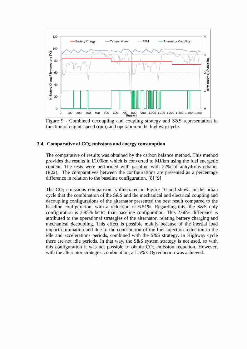
Figure 9 - Combined decoupling and coupling strategy and S&S representation in
function of engine speed (rpm) and operation in the highway cycle.
3.4. Comparative of CO2 emissions and energy consumption
The comparative of results was obtained by the carbon balance method. This method
provides the results in l/100km which is converted to MJ/km using the fuel energetic
content. The tests were performed with gasoline with 22% of anhydrous ethanol
(E22). The comparatives between the configurations are presented as a percentage
difference in relation to the baseline configuration. [8] [9]
The CO2 emissions comparison is illustrated in Figure 10 and shows in the urban
cycle that the combination of the S&S and the mechanical and electrical coupling and
decoupling configurations of the alternator presented the best result compared to the
baseline configuration, with a reduction of 6.51%. Regarding this, the S&S only
configuration is 3.85% better than baseline configuration. This 2.66% difference is
attributed to the operational strategies of the alternator, relating battery charging and
mechanical decoupling. This effect is possible mainly because of the inertial load
impact elimination and due to the contribution of the fuel injection reduction in the
idle and accelerations periods, combined with the S&S strategy. In Highway cycle
there are not idle periods. In that way, the S&S system strategy is not used, so with
this configuration it was not possible to obtain CO2 emission reduction. However,
with the alternator strategies combination, a 1.5% CO2 reduction was achieved.

Figure 10 - CO2 reduction in urban and highway cycles.
The Figure 11 shows the results in terms of reduction of energy consumption
(MJ/km) percentage in the three phases of FTP 75 (urban cycle). In Phases I, II and II
the S&S combined with the alternator strategies had better results, because even with
the cold engine periods, there were decoupling events with reduction of the fuel
injection in the periods of idle and acceleration. In Phases II and III the reductions in
energy consumption followed the behavior of CO2 reductions.
Figure 11 - Energy consumption reduction in Phases 1, 2 and 3 of urban cycle
Figure 12 summarizes the energy consumption reduction results of the Urban,
Highway and combined cycles with all the possible technologies configurations of
this study. According to the balance carbon method, the energy consumption results
were calculated from emissions values in each cycle. Consequently, the reductions of
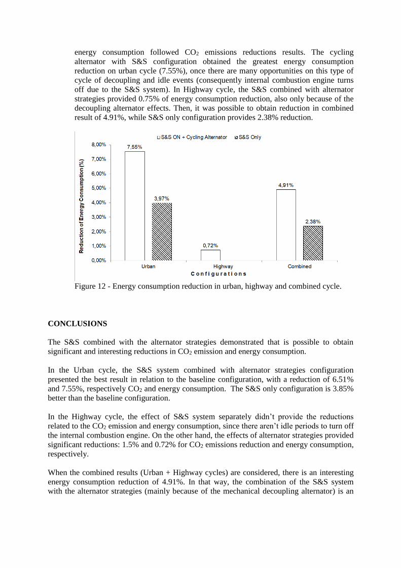
energy consumption followed CO2 emissions reductions results. The cycling
alternator with S&S configuration obtained the greatest energy consumption
reduction on urban cycle (7.55%), once there are many opportunities on this type of
cycle of decoupling and idle events (consequently internal combustion engine turns
off due to the S&S system). In Highway cycle, the S&S combined with alternator
strategies provided 0.75% of energy consumption reduction, also only because of the
decoupling alternator effects. Then, it was possible to obtain reduction in combined
result of 4.91%, while S&S only configuration provides 2.38% reduction.
Figure 12 - Energy consumption reduction in urban, highway and combined cycle.
CONCLUSIONS
The S&S combined with the alternator strategies demonstrated that is possible to obtain
significant and interesting reductions in CO2 emission and energy consumption.
In the Urban cycle, the S&S system combined with alternator strategies configuration
presented the best result in relation to the baseline configuration, with a reduction of 6.51%
and 7.55%, respectively CO2 and energy consumption. The S&S only configuration is 3.85%
better than the baseline configuration.
In the Highway cycle, the effect of S&S system separately didn’t provide the reductions
related to the CO2 emission and energy consumption, since there aren’t idle periods to turn off
the internal combustion engine. On the other hand, the effects of alternator strategies provided
significant reductions: 1.5% and 0.72% for CO2 emissions reduction and energy consumption,
respectively.
When the combined results (Urban + Highway cycles) are considered, there is an interesting
energy consumption reduction of 4.91%. In that way, the combination of the S&S system
with the alternator strategies (mainly because of the mechanical decoupling alternator) is an

excellent technological option to apply in automotive industry in order to attend the global
legislations regarding energy efficient improvements and CO2 reductions.
REFERÊNCIAS
[1] SALES L.C.M., Patent Process INPI BR Nº 10 2015 001454 6. 2015.
[2] SALES L.C.M., US Patent 10,247,265 B2. 2019
[3] SALES, L C. M.., PACHECO, E., MONTEIRO, L. G. C., et al. Evaluation of the
influence of an alternator with mechanical decoupling on energy consumption and CO2
emission in a flex fuel vehicle. SAE Technical Paper, 2017-36-0116, 2017.
[4] KRAIL, M. Technologies and incentives to reduce CO2 emissions from passenger cars.
GHG-TrasnporD Workshop 3. Berlin Seminar in Energy and Climate (BSEC), Berlim,
2010.
[5] BOSCH; Bosch Mobility Solutions – Electronic Battery Sensor. Disponível em
http://products.bosch-mobility-solutions.com/en/de/_technik/component/CO_CV_ES_Body-
Electronics_CO_CV_Electronic-Systems_2202.html?compId=1175. Acesso em 03/02/2019
[6] CONTINENTAL; Intelligent Battery Sensor. Disponível em http://www.continental-
automotive.com/www/automotive_de_en/themes/passenger_cars/chassis_safety/passive_safet
y_sensorics/ov_battery_sensors_en/intelligent_battery_sensor_en.html. Acesso em:
10/12/2018.
[7] SALES, L C. M.., SOUSA, J. M. S., MONTEIRO, L. G. C., et al. Experimental
comparative analysis of the combined Stop & Start and alternator with mechanical decoupling
strategies. SAE Technical Paper, 2018-36-0341, 2018
[8] ASSOCIAÇÃO BRASILEIRA DE NORMAS TÉCNICAS. ABNT NBR 6601: Veículos
rodoviários automotores leves: Determinação de hidrocarbonetos, monóxido de carbono,
óxidos de nitrogênio, dióxido de carbono e material particulado no gás de escapamento. Rio
de Janeiro, 2012.
[9] ASSOCIAÇÃO BRASILEIRA DE NORMAS TÉCNICAS. ABNT NBR 7024: Veículos
Rodoviários Automotores Leves – Medição do Consumo de Combustível - Método de Ensaio.
Rio de Janeiro, 2017.