automotive vehicles - spray-suppression systems · pdf fileautomotive vehicles –...
TRANSCRIPT

Draft AIS-013 (Rev.1)/D2 September 2013
I
AUTOMOTIVE INDUSTRY STANDARD
Automotive Vehicles - Spray-Suppression Systems
(Revision 1)
Date of hosting on website: 2nd September 2013
Last date for comments: 1st October 2013

Draft AIS-013 (Rev. 1)/ D2 September 2013
II
CHECK LIST FOR PREPARING REVISION TO
AUTOMOTIVE INDUSTRY STANDARD (AIS)
AIS-013 (Rev.1):2013 Automotive Vehicles - Spray-Suppression Systems
SR. NO.
PARTICULARS REMARKS
1. Indicate details of the base reference standard. (e.g. ECE/ EEC directive/GTR, etc…)
Directive 91/226/EEC
1.1 Latest version of the base standard (Sr. No.1) considered for the alignment of this standard.
Regulation (EU) No 109/2011
2. Add an explanatory note indicating differences between the above standard and this standard, if any.
The scope changed to include N1 and N2 up to 7.5 T category vehicles.
3. Are the details of technical specifications to be submitted at the time of type approval relevant to the requirements of this standard covered?
Yes. Refer clause 2.2 of Part-II & clause 1.2 of Part-III
4. Are the performance requirements covered? Yes. Refer clause 4 of Appendix 1 & Appendix 2
5. Is there a need to specify dimensional requirements? If yes, are they covered?
Yes. Refer clause 3.0 & 5.0 of General requirements and clause 6.0, 7.0 & 8.0 of Specific requirements
6. Are the details of Criteria for Extension of Type Approval covered?
Yes. Refer clause 1.4 of Part-III
7. Is AIS-037 applicable for the devices covered in this standard, If yes:
No
7.1 Is there a need to specify COP requirements? If yes, are following covered?
No
7.2 Tests/checks needed for COP
No
7.3 Periodicity of COP
Not applicable
7.4 Have the transitional provisions for extension of AIS-037 approval been covered?
Not applicable
7.5 Has the “type” been defined?
Yes. Refer clause 6.0 of Part-I
8. Is this standard covers the requirements of E/e approved components?
No
9. Are the provisions for further amendments in ECE regulations addressed?
No
10. Is the standard is intended for replacing or revising an already notified standard, if yes:
Yes
10.1 Are the Transitional provisions for re-certification of already certified parts/vehicles by comparing the previous test result, certain additional test, etc. covered
Yes. Refer clause 1.5 of Part-III

Draft AIS-013 (Rev. 1)/ D2 September 2013
III
10.2 Can this standard be permitted in lieu of the existing notified standard from the date of adoption of this standard by CMVR TSC?
Yes
10.2.1 If so has this been included in the transitional provisions
Yes
10.3 Have all the transitional provisions been covered?
Yes
11. Status of availability of test facilities with approved test agencies?
ARAI/iCAT/CIRT/VRDE
12. Are there any points on which special comments or information is to be invited from members?
If yes, are they identified?
All the points are discussed in AISC and arrived at consensus.
13. Do components / vehicles manufacturers / Test agencies require lead time to meet requirements of revision?,
Yes
13.1 Recommendation of date for implementation of revision.
New Models: 1Year Existing Models: 2Year
14. Is proposed draft notification prepared?
To be prepared
15. Has the clarity of classification been examined?
Yes
16. Has the clarity of definitions been examined?
Yes

Draft AIS-013 (Rev. 1)/ D2 September 2013
IV
Status Chart of the Standard to be used by the purchaser for updating the record Sr. No.
Corrigenda Amendment Revision Date Remark Misc.
General Remarks:

Draft AIS-013 (Rev. 1)/ D2 September 2013
V
INTRODUCTION
The Government of India felt the need for a permanent agency to expedite the publication of standards and development of test facilities in parallel when the work on the preparation of the standards is going on, as the development of improved safety critical parts can be undertaken only after the publication of the standard and commissioning of test facilities. To this end, the Ministry of Surface Transport (MOST) has constituted a permanent Automotive Industry Standard Committee (AISC) vide order No. RT-11028/11/97-MVL dated September 15, 1997. The standards prepared by AISC will be approved by the permanent CMVR Technical Standing Committee (CTSC). After approval, the Automotive Research Association of India, (ARAI), Pune, being the secretariat of the AIS Committee, has published this standard. For better dissemination of this information ARAI may publish this document on their Web site. In the process of harmonizing the Indian Standards with the EEC directive / UN regulation the requirements of the spray - suppression devices for automotive vehicles were deliberated. This standard was based on EEC Directive 91/226/EEC which has been recently amended by Commission Regulation (EU) No 109/2011 with change in the scope. It was felt necessary to revise AIS-013 to include the change in scope and to cover N1, N2 ≤ 7.5T category of vehicles. The standard covers the requirements of the fitment of spray - suppression devices on the vehicles. The standard also covers the performance requirements and the component type approval of two types of devices namely the energy absorption type and the air/water separator type. The AISC panel and the Automotive Industry Standards Committee (AISC) responsible for preparation of this standard are given in Annexure 1 (To be included) and Annexure 2 (To be included) respectively.
Draft AIS-013 (Rev. 1): 2013 / D2 23rd July 2013
1/25
Automotive Vehicles – Spray-Suppression Systems
1. SCOPE This Standard specifies the performance, dimensional and fitment requirements of spray-suppression systems in following category of automotive vehicles: All N, T3 and T4 category vehicles shall be constructed and or fitted with spray-suppression devices in such a way as to meet the requirements of this standard. Vehicles of category N1 and N2 with Gross Vehicle Weight (GVW) not exceeding 7.5 tonnes, complying the requirements of IS 13943: 1994, shall be deemed to meet the requirements of this standard. The requirements laid down relating to spray-suppression devices as defined in clause 1.4 of Part I are not mandatory in the case of chassis/cab vehicles, un-bodied vehicles, ‘off-road’ vehicles in which the presence of spray-suppression devices is incompatible with their use. However, if such devices are fitted to these vehicles, they shall conform to the requirements of this Standard.
2. REFERENCE
2.1 IS: 14272 – 1995 Automotive Vehicles – Types Terminology – Part 1 – Three and Four Wheelers.
2.2 IS: 9211–1979 - Denominations and Definitions of Weights of Road Vehicles.
2.3 IS 13943:1994 - Automotive Vehicles — Wheel Guards for passenger cars — performance requirements
3. CONTENTS
The requirements of spray-suppression devices in automotive vehicles as per this standard have been covered in the following three parts.
PART I : General definitions
PART II : Requirements relating to the component type – approval of spray-suppression devices.
Appendix 1: Tests on spray-suppression devices of the energy absorber type
Appendix 2: Tests on spray-suppression devices of the air / water
separator type
PART III: Requirements relating to the type approval of a vehicle with regard to fitment of spray-suppression systems.

Draft AIS-013 (Rev. 1)/ D2 September 2013
2/25
PART- I
1.0 DEFINITIONS
For the purposes of this standard, the following definitions shall apply:
1.1 Spray-Suppression System
Means a system intended to reduce the pulverization of water thrown upwards by the tyres of a vehicle in motion. The spray-suppression system is variously made up of a mudguard, rain flaps and valances equipped with a spray-suppression device.
1.2 Mudguard
‘Mudguard’ means a rigid or semi-rigid component intended to trap the water thrown up by tyres in motion and to direct it towards the ground. Mudguards may entirely or partially form an integral part of the vehicle bodywork or other parts of the vehicle such as the lower part of the load platform, etc.
1.3 Rain flap
Means a flexible component mounted vertically behind the wheel, on the lower part of the chassis or the loading surface, or on the mudguard.
The rain flap shall also reduce the risk of small objects, in particular pebbles, being picked up from the ground by the tyres and thrown upwards or side wards towards other road users.
1.4 Spray-suppression device Means part of the spray-suppression system, which may comprise: 1.4.1 Air / water separator
This is a component forming part of the valance and /or of the rain flap through which air can pass whilst reducing pulverized water emissions.
1.4.2 Energy absorber
This is a component forming part of the mudguard and / or valance and /or rain flap which absorbs the energy of water spray, thus reducing pulverized water spray.
1.5 Outer valance
means a component located approximately within a vertical plane that is parallel to the longitudinal plane of the vehicle. It may form part of a mudguard or of the vehicle bodywork.

Draft AIS-013 (Rev. 1)/ D2 September 2013
3/25
1.6 Steered wheels
Means the wheels actuated by the vehicle’s steering system.
1.7 Self-tracking axle
Means an axle pivoted about a central point in such a way that it can describe a horizontal arc. For the purpose of this Standard, a self-tracking axle of the `pivot steering’ type is considered to be, and treated as, an axle fitted with steered wheels.
2 SELF-STEERED WHEELS
means wheels not actuated by the vehicle’s steering device, which may swivel through an angle not exceeding 20 deg. owing to the friction exerted by the ground.
3 LIFTING AXLE
Means an axle, which can be lifted from the road during normal vehicle use.
4 UNLADEN VEHICLE
Means a vehicle in the form given in clause 3.2, to 3.6 of IS : 9211-1979 depending on the configuration of the vehicle submitted for Type Approval of the spray-suppression device / system.
5 TYRE CONTACT PATCH
Means the part of the tyre, in contact with the road (surface), which provides grip.
6 TYPE OF SPRAY-SUPPRESSION DEVICE Means devices which do not differ with respect to the following main characteristics: - The physical principle adopted in order to reduce emissions (water-
energy absorption, air/water separator), - Materials,
- Shape,
- Dimensions (in so far as they may influence the behavior of the
material).

Draft AIS-013 (Rev. 1)/ D2 September 2013
4/25
PART II
REQUIREMENTS RELATING TO THE COMPONENT TYPE-APPROVAL OF SPRAY-SUPPRESSION DEVICES
0. GENERAL SPECIFICATIONS 0.1. Spray-suppression devices shall be constructed in such a way that they
operate properly when used normally on wet roads. Moreover, they shall incorporate no structural or manufacturing defect detrimental to their proper functioning or behavior.
1. TESTS TO BE CARRIED OUT 1.1. Depending on their physical operating principle spray-suppression devices
are subjected to the relevant tests as described in Appendices 1 and 2 and shall deliver the results required in Cl. 4 of those Appendices.
2. APPLICATION FOR COMPONENT TYPE -APPROVAL 2.1 The application for component Type - Approval of a type of
spray -suppression device shall be submitted by the manufacturer to the Test Agency.
2.2 For each type, the application shall be accompanied by the following
documents in A4 or folded A4 size and the following information. 2.2.1 A technical description of the spray - suppression device indicating its
physical operating principle and the relevant test to which it shall be subjected, the materials used and one or more drawings in sufficient detail and to an appropriate scale to enable this ( or these ) to be identified.
2.2.2 Four samples, shall be provided out of which three shall be used for
tests and the fourth shall be kept by the Testing Agency for any subsequent verification. The Test Agency may require further samples.
2.3 Markings: Each sample shall be clearly and indelibly marked with the trade name
or mark and an indication of the type of the spray - suppression device by the letter ‘A’ or the letter ‘ S’ depending on whether the device is of the energy absorption type (A) or of the air / water separator type (S).

Draft AIS-013 (Rev. 1)/ D2 September 2013
5/25
Appendix 1
TESTS ON SPRAY-SUPPRESSION DEVICES OF THE ENERGY-ABSORBER TYPE
1. PRINCIPLE
The aim of these tests is to quantify the ability of a device to retain the water directed against it by a series of jets. The test assembly is intended to reproduce the conditions under which the device is to function when fitted to a vehicle as regards the volume and speed of the water thrown up from the ground by the tyre tread.
2. EQUIPMENT
See Figure 8 for description of the test assembly. The tests are carried out in a still-air environment.
3. PROCEDURE
3.1. Secure a 500 (+0 / -5) mm wide, 750 mm high sample of the device to be tested to the vertical frame of the testing equipment, making sure that the sample lies well within the limits of the collector, and that no obstacle is able to deflect the water, either before or after its impact.
3.2. Set the water flow rate at 0.675 (±0.01) l/s and direct at least 90 l on to the sample from a horizontal distance of 500 (± 2) mm (Figure 8).
3.3. Allow the water to trickle from the sample into the collector and calculate the percentage (difference) between the quantity of water collected and the quantity of water sprayed.
3.4. Repeat the test five times and calculate the average percentage amount of
water collected.
4. RESULTS
4.1. The calculated average percentage of water collected during the five tests shall not be less than 70% of the amount of water directed on to the device.
4.2 If the highest and lowest percentages of water collected depart from the average percentage by more than 5%, the test is not valid and must be repeated
If even in the second test the highest and lowest percentages of water recovered again depart from the average percentage by more than 5% and/or if the lower value does not satisfy the requirements of item 4.1, approval is refused.
4.3 Where the vertical position of the device influences the results obtained,
the procedure described in items 3.1 and 3.4 shall be repeated in the positions giving the highest and lowest percentage of water collected the requirements of Cl. 4.2 remain in force.
The requirements of item 4.1 remain in force in order to give the result of each test.

Draft AIS-013 (Rev. 1)/ D2 September 2013
6/25
Appendix 2
TEST ON SPRAY-SUPPRESSION DEVICES OF THE AIR / WATER SEPARATOR TYPE
1. PRINCIPLE
This test is intended to determine the effectiveness of a porous material intended to retain the water with which it has been sprayed by means of a pressurized air/water pulverizer.
The equipment used for the test shall simulate the conditions to which the material would be submitted, with regard to the volume and speed of the water spray produced by the tyres, if it were fitted to a vehicle.
2. EQUIPMENT
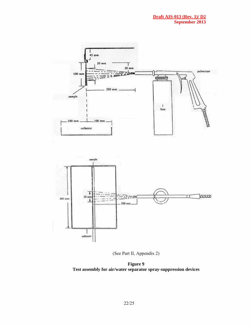
2.1 The test assembly is as described in Figure 9.
3. PROCEDURE
Secure a 305 x 100 mm sample vertically in the test assembly; check that there is no space between the sample and the upper curved plate and that the tray is properly in position. Fill the pulverizer tank with exactly one liter of water and place this as described in the diagram.
The pulverizer shall be regulated as follows:
Pressure (at pulverizer): 5 bar + 10%/ - 0%
Flow rate: 1 litre / minute + 5 seconds
Pulverization: Circular, roughly 50 mm in diameter at 200 mm from the sample, nozzle 5 mm in diameter.
Pulverize until there is no more water mist and note the time taken. Let the water flow out of the sample on to the tray for 60 seconds and measure the volume of water collected. Measure the quantity of water left in the pulverizer tank. Calculate the percentage by volume of water collected versus the volume of water pulverized.
Repeat the test five times and calculate the average percentage of the quantity collected. Check before each test that the tray, pulverizer tank and measuring vessel are dry.
During the test the ambient temperature shall be 27 (±5) C. 4. RESULTS 4.1 The calculated average percentage of water collected at the end of five
tests shall not be less than 85% of the quantity of water sprayed on to the device.
4.2 If the highest and lowest percentages of water collected vary by more than
5% of the average percentage, the test is not valid and shall be repeated.

Draft AIS-013 (Rev. 1)/ D2 September 2013
7/25
If even in the second test, the highest and lowest percentages of water recovered again depart from the average percentage by more than 5% and/or if the lower value does not satisfy the requirements of Cl. 4.1, approval is refused.
4.3 Where the vertical position of the device influences the results obtained,
the procedure described in items 3.1 and 3.4 shall be repeated in the positions giving the highest and lowest percentages of water collected; the requirements of Cl. 4.2 remain in force.
The requirement of Cl. 4.1 remains in force in order to give the results of each test.

Draft AIS-013 (Rev. 1)/ D2 September 2013
8/25
PART III
REQUIREMENTS RELATING TO THE TYPE-APPROVAL OF A TYPE OF VEHICLE WITH REGARD TO THE FITMENT OF
SPRAY-SUPPRESSION SYSTEM
0.0 SCOPE 0.1. All N, T3 and T4 category vehicles shall be constructed and or fitted with
spray-suppression devices in such a way as to meet the requirements described in clauses 2.0 and onwards as below.
However, vehicles of category N1 and N2 with a Gross Vehicle Weight (GVW) not exceeding 7.5 tonnes, complying the requirements of IS 13943: 1994 shall be deemed to meet the requirements of this standard.
0.2. The requirements laid down above relating to spray-suppression devices as defined in Para 4 of Part I are not mandatory in the case of chassis/cab vehicles, un-bodied vehicles, ‘off-road’ vehicles in which the presence of spray-suppression devices is incompatible with their use. However, if such devices are fitted to these vehicles, they must conform to the requirements of this Standard.
1.0 APPLICATION FOR TYPE - APPROVAL 1.1 The application for type - approval of a vehicle type with regard to
the fitting of a spray -suppression system shall be submitted by the vehicle manufacturer.
1.2 It shall be accompanied by the following documents having the following particulars :
1.2.1 A technical description of the spray - suppression system and one or
more sufficiently detailed drawing on a scale suitable for identification.
1.3 A vehicle representative of the vehicle type to be approved, fitted with its spray suppression system, shall be submitted to the Test Agency conducting the approval tests.
1.4 Criteria for Extension of Type Approval :
In the case of Type-Approval of a number of models /variants fitted with the spray suppression devices of the same type, the Type approval / extension of type approval may be granted if the following conditions are met:
Draft AIS-013 (Rev. 1)/ D2 September 2013
9/25
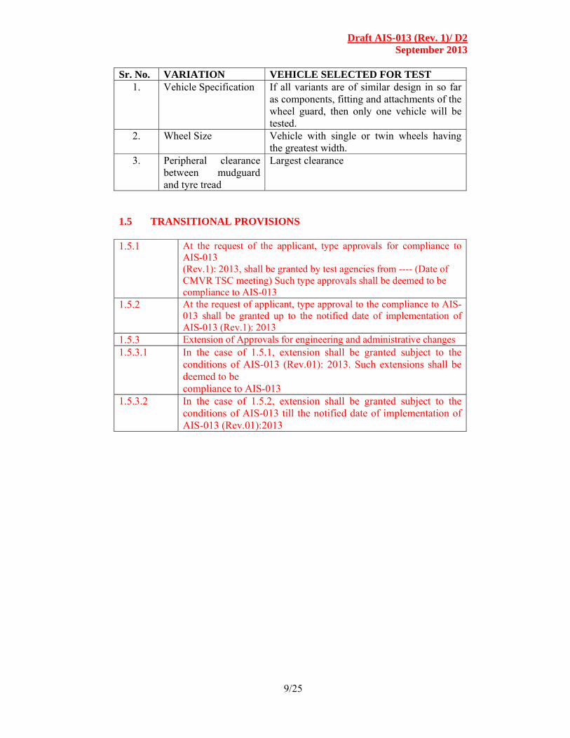
Sr. No. VARIATION VEHICLE SELECTED FOR TEST 1. Vehicle Specification If all variants are of similar design in so far
as components, fitting and attachments of the wheel guard, then only one vehicle will be tested.
2. Wheel Size Vehicle with single or twin wheels having the greatest width.
3. Peripheral clearance between mudguard and tyre tread
Largest clearance
1.5 TRANSITIONAL PROVISIONS 1.5.1 At the request of the applicant, type approvals for compliance to
AIS-013 (Rev.1): 2013, shall be granted by test agencies from ---- (Date of CMVR TSC meeting) Such type approvals shall be deemed to be compliance to AIS-013
1.5.2 At the request of applicant, type approval to the compliance to AIS-013 shall be granted up to the notified date of implementation of AIS-013 (Rev.1): 2013
1.5.3 Extension of Approvals for engineering and administrative changes 1.5.3.1 In the case of 1.5.1, extension shall be granted subject to the
conditions of AIS-013 (Rev.01): 2013. Such extensions shall be deemed to be compliance to AIS-013
1.5.3.2 In the case of 1.5.2, extension shall be granted subject to the conditions of AIS-013 till the notified date of implementation of AIS-013 (Rev.01):2013
Draft AIS-013 (Rev. 1)/ D2 September 2013
10/25
GENERAL REQUIREMENTS
2.0 Axles
2.1 Lifting axles
Where a vehicle is fitted with one or more lifting axles, the spray-suppression system shall cover all the wheels when the axle is lowered and the wheels in contact with the ground when the axle is raised.
2.2 Self-tracking axles
Where a vehicle is fitted with a self-tracking axle, the spray-suppression system shall satisfy the conditions applicable to non-steered wheels if mounted on the pivoting part. If not mounted on that part, it shall satisfy the conditions that are applicable to steered wheels.
3 POSITION OF OUTER VALANCE 3.1 In the case of non-steered wheels distance ‘C’ between the longitudinal
plane tangential to the outer tyre wall, apart from any tyre bulge near the ground, and the inner edge of the valance shall not exceed 75 mm unless the radius of the inner edge of the valance, as defined in Para 6.2, 7.2 and 8.2 is less than 1.0 R, in which case it shall not exceed 100 mm (Figure 1).
3.2 In the case of steered and self-steered wheels, distance ‘C’ shall not exceed 100 mm.
4 STATE OF VEHICLE
For the checking of compliance with this Standard the vehicle shall be in the following state:
4.1 It shall be unladen and with the wheels in the straight-ahead position;
4.2 In the case of semi-trailers, the loading surfaces shall be horizontal;
4.3 The tyres shall be inflated to their normal pressure.
5 SPRAY-SUPPRESSION SYSTEMS
5.1 The spray-suppression system shall meet the specifications set out in Cl. 6 or 8.
5.2 The spray-suppression system for non-steered or self steered wheels that
are covered by the bodywork floor, or by the lower part of the load platform, shall meet either the specifications set out in Cl. 6 or 8 or else those in Cl. 7.
SPECIFIC REQUIREMENTS
6. REQUIREMENTS CONCERNING ENERGY ABSORPTION
SPRAY SUPPRESSION SYSTEMS FOR AXLES FITTED WITH STEERED OR SELF STEERING OR NON-STEERED WHEELS.
Draft AIS-013 (Rev. 1)/ D2 September 2013
11/25
6.1 Mudguards
6.1.1 The mudguards shall cover the zone immediately above, ahead and behind the tyre or tyres in the following manner :
(a) In the case of a single or multiple axle where distance ‘d’ (Figure 4) between the tyres fitted to the adjacent axles exceeds 300 mm, the forward edge (C) shall extend forwards to reach a line O – Z where angle (theta) = no more than 30 deg above the horizontal for axles fitted with steering or self-steering wheels, and no more than 20 deg for axles fitted with non-steered wheels.
The rearmost edge (Figure 2) shall extend downwards in such a way as not to be more than 100 mm above a horizontal line passing through the centre of the wheel.
(b) In the case of multiple axles where the distance ‘d’ between the tyres fitted to the adjacent axles does not exceed 300 mm, the mudguard shall be as shown in Figure 4a.
(c) The mudguard shall possess a total width ‘q’ (Figure 1) at least adequate to cover the entire width of the tyre ‘b’ or the entire width of two tyres ‘t’ in the case of twin wheels, account being taken of the extremes for the tyre/wheel unit specified by the manufacturer. Dimensions ‘b’ and ‘t’ shall be measured at hub height, excluding any markings, ribs, protective bands, etc., on the tyre walls.
6.1.2 The front side of the rear part of the mudguard shall be fitted with a spray-
reduction device complying with the specifications set out in Appendix 1 to Part II. This material shall cover the inside of the mudguard up to a height determined by a straight line running from the centre of the wheel and forming an angle of at least 30 deg with the horizontal (Figure 3).
6.1.3 If the mudguards are made up of several components when fitted, they
shall not incorporate any aperture enabling spray to exit while the vehicle is in motion.
6.2 OUTER VALANCES 6.2.1 In the case of single axles, or multiple axles where distance ‘d’ between
the tyres on adjacent axles exceeds 300 mm, the lower edge of the outer valance may not be situated beyond the following distances and radii, as measured from the centre of the wheel (Figure 2).

Draft AIS-013 (Rev. 1)/ D2 September 2013
12/25
(a) Axles fitted with steered wheels or self steering wheels;
From the front edge (towards the front of the vehicle) Rv 1.5 R
(tip C at 30 deg) To the rear edge ( towards the rear of the vehicle)
(tip A at 100 mm)
(b) Axles fitted with non-steered wheels: From the front edge (tip C at 20 deg) Rv 1.25 R To the rear edge (tip A at 100 mm)
Where R is the radius of the tyre fitted to the vehicle, and Rv the distance, expressed as a radius, at which the lower edge of the outer valance is situated.
6.2.2 In the case of multiple axles where distance ‘d’ between the tyres on
adjacent axles does not exceed 300 mm, the outer valances located in the space between the axles shall be located at the distances set out in item 6.2.1 and shall extend downwards in such a way as not to be more than 150 mm above a horizontal line passing through the centre of the wheels, or in such a way that the horizontal distance between their lower extremities does not exceed 60 mm (Figure 4a).
6.2.3 The depth of the outer valance shall extend to not less than 45 mm, at all
points behind a vertical line passing through the centre of the wheel. The depth of the valances may be gradually reduced in front of this line.
6.2.4 No openings enabling spray to emerge when the vehicle is moving are
allowed in the outer valances or between the outer valances and the other parts of the mudguards.
6.3 RAIN FLAPS 6.3.1 The width of the flap shall fulfill the requirement for ‘q’ in Cl. 6.1.1 (C)
except where the flap is within the mudguards, in which case it shall be at least equal in width to the tread of the tyre.
6.3.2 The orientation of the flap shall be basically vertical. 6.3.3 The maximum height of the bottom edge shall not exceed 200 mm (Figure
3). This distance is increased to 300 mm in the case of the last axle where the radial distance of the lower edge of the outer valancing, Rv does not exceed the dimensions of the radius of the tyres fitted to the wheels on that axle.
6.3.4 The rain flap shall not be more than 300 mm from the rearmost edge of the
tyre, measured horizontally.

Draft AIS-013 (Rev. 1)/ D2 September 2013
13/25
6.3.5 In the case of multiple axles where distance ‘d’ between the tyres on adjacent axles is less than 250 mm, only the rear set of wheels shall be fitted with rain flaps. There shall be a rain flap behind each wheel when distance ‘d’ between the tyres on adjacent axles is at least 250 mm (Figure 4b).
6.3.6 Rain flap shall not be deflected by more than 100 mm towards the rear
under a force of 3 N per 100 mm of flap width, applied to a point located 50 mm above the lower edge of the flaps.
6.3.7 The whole of the front face of the part of the rain flap having the
minimum dimensions required shall be fitted with a spray-suppression device that meets the specifications set out in Part II, Appendix 1.
6.3.8 No openings enabling spray to emerge are allowed between the lower rear
edge of the mudguard and the rain flaps. 6.3.9 Where the spray-suppression device meets the specifications relating to
rain flaps (Cl. 5.3), no additional rain flap is required. 7.0 REQUIREMENTS RELATING TO SPRAY SUPPRESSION
SYSTEMS FITTED WITH ENERGY ABSORPTION SPRAY-SUPPRESSION DEVICES FOR CERTAIN AXLES THAT ARE FITTED WITH NON-STEERED OR SELF-STEERING WHEELS (SEE CL. 5.2)
7.1 Mudguards 7.1.1 Mudguards shall cover the zone immediately above the tyre or tyres. Their
front and rear extremities shall extend at least to the horizontal plane that is tangent to the upper edge of the tyre or tyres (Figure 5). However, the rear extremity may be replaced by the rain flap, in which case this shall extend to the upper part of the mudguard (or equivalent component)
7.1.2 All of the inner rear part of the mudguard shall be fitted with a
spray- suppression device that meets the requirement set out in Part II, Appendix 1.
7.2 Outer Valances
7.2.1 In the case of single or multiple axles where the distance between the
adjacent tyres is at least 250 mm, the outer valance shall cover the surface extending from the lower to the upper part of the mudguard up to a straight line formed by the tangent to the upper edge of the tyre or tyres and lying between the vertical plane formed by the tangent to the front of the tyre and the mudguard or rain flap located behind the wheel or wheels (Figure 5b).
In the case of multiple axles, an outer valance shall be located by each wheel.

Draft AIS-013 (Rev. 1)/ D2 September 2013
14/25
7.2.2 No openings enabling spray to emerge are allowed between the outer valance and the inner part of the mudguard.
7.2.3 Where rain flaps are not fitted behind each wheel (see Cl. 6.3.5), the outer valance shall be unbroken between the outer edge of the rain flap to the vertical plane that is tangent to the point furthest to the front of the tyre (Figure 5a) of the first axle.
7.2.4 The entire inner surface of the outer valance, the height of which shall not be less than 100 mm, shall be fitted with an energy-absorption spray-suppression device complying with the requirements of Part II.
7.3 Rain Flaps
These flaps shall extend to the lower part of the mudguard and comply with Cl. 6.3.
8.0 REQUIREMENTS CONCERNING SPRAY-SUPPRESSION SYSTEMS FITTED WITH AIR/WATER SEPARATOR SPRAY-SUPPRESSION DEVICES FOR AXLES WITH STEERED AND NON-STEERED WHEELS.
8.1 Mudguards
8.1.1 Mudguards shall comply with the requirements of Cl. 6.1.1 (c).
8.1.2 Mudguards for single or multiple axles where the distance between the tyres on adjacent axles exceeds 300 mm shall also comply with item 6.1.1(a).
8.1.3 In the case of multiple axles where the distance between the tyres on adjacent axles does not exceed 300 mm, the mudguards shall also conform to the model shown in Figure 7.
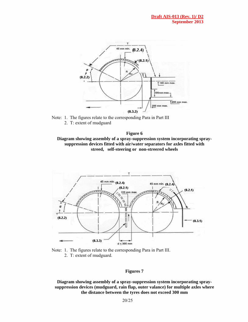
8.2 Outer Valances 8.2.1 The lower edges of the outer valances shall be fitted with air/water
separator spray-suppression devices complying with the requirements of Part II.
8.2.2 In the case of single or multiple axles where the distance between the tyres
on adjacent axles exceeds 300mm, the lower edge of the spray-suppression device fitted to the outer valance shall have the following maximum dimensions and radii, starting from the centre of the wheel (Figures 6 and 7):
(a) Axles fitted with steered wheels or self-steering wheels:
From the front edge (towards the front of the vehicle) Rv 1.05 R (tip C at 30 deg) to the rear edge (towards the rear of the vehicle) (tip A at 100 mm).

Draft AIS-013 (Rev. 1)/ D2 September 2013
15/25
(b) Axles fitted with non-steered wheels;
From the front edge (tip C at 20 deg) Rv 1.00 R to the rear edge (tip A at 100 mm).
Where R = is the radius of tyre fitted to the vehicle;
Rv = the radial distance from the lowest edge of the
outer valance to the centre of the wheel.
8.2.3 In the case of multiple axles where the distance between the tyres on adjacent axles does not exceed 300 mm, the outer valances located in the inter-axle spaces shall follow the path specified in Para 8.1.3, and shall extend downwards in such a way as not to be more than 100 mm above a horizontal straight line passing through the wheel centers (Figure 7).
8.2.4 The depth of the outer valance shall extend to not less than 45 mm, at all points behind a vertical line passing through the centre of the wheel. This depth may be gradually reduced in front of this line.
8.2.5 No openings enabling spray to emerge are allowed in the outer valances or between the outer valances and the mudguards.
8.3 Rain Flaps
8.3.1 Rain flaps shall:
(a) Comply with Para 6.3 (Figure 3); or (b) Comply with Para 6.3.1,6.3.5, 6.3.8 and 8.3.2 (Figure 6).
8.3.2 Spray suppression device complying with the specifications set out in
Part II, Appendix 2, shall be fitted to the rain flaps referred to in Cl. 8.3.1 (b), at least along the full edge.
8.3.2.1 The lower edge of the spray-suppression device shall be not more than 200 mm from the ground.
8.3.2.2 The spray suppression device shall be at least 100 mm deep.
8.3.2.3 Apart from the lower part, which includes the spray-suppression device, the rain flap as referred to in para 8.3.1 (b) shall not bend by more than 100 mm towards the rear under the effect of a force of 3 N per 100 mm of width of the rain flap measured at the intersection of the rain flap with the spray-suppression device in its working position, applied at a distance of 50 mm above the lower edge of the rain flap.
8.3.3 The rain flap shall not be more than 200 mm from the rearmost edge of the tyre, measured horizontally.
Explanatory Note:
For preparation of this standard considerable assistance has been taken from EEC Directive 91/226/EEC, Jan. 1995.

Draft AIS-013 (Rev. 1)/ D2 September 2013
16/25
Note: The figures refer to the corresponding Para in Part III.
Figure 1
Width (q) of mudguard (a) and position of valance (j)

Draft AIS-013 (Rev. 1)/ D2 September 2013
17/25
Note: 1. The figures quoted relate to the corresponding Paras in Part III. 2. T: extent of mudguard
Figure 2
Dimensions of mudguard and outer valance
Note: The Figures quoted relate to the corresponding Paras in Part III.
Figure 3
Position of mudguard and rain flap

Draft AIS-013 (Rev. 1)/ D2 September 2013
18/25
(a) Dimensions of mudguards and outer valances for multiple axles
Note: 1. The figures quoted relate to the following items in Part III. 2. T: extent of mudguard
(b) Position of spray-suppression devices for multiple axles
Note: The figures relate to the corresponding items in Part III.
Figure 4
Mudguards and outer valance for steered or self-steering or non-steered wheels
60 mm max. 150 mm max (6.2.2)

Draft AIS-013 (Rev. 1)/ D2 September 2013
19/25
(a) Multiple axles where the distance between the tyres in less than 250 mm
(b) Single axles or multiple axles where the distance between the tyres in not less
than 250 mm Part III – Paras 5.2 and 7
Figure 5
Diagram showing assembly of a spray-suppression system incorporating
spray-suppression devices fitted with energy absorbers for axles fitted with non-steered or self-steering wheels
Paras. 7.1 & 7.3
Draft AIS-013 (Rev. 1)/ D2 September 2013
20/25
Note: 1. The figures relate to the corresponding Para in Part III 2. T: extent of mudguard
Figure 6 Diagram showing assembly of a spray-suppression system incorporating spray-
suppression devices fitted with air/water separators for axles fitted with streed, self-steering or non-streered wheels
Note: 1. The figures relate to the corresponding Para in Part III. 2. T: extent of mudguard.
Figures 7
Diagram showing assembly of a spray-suppression system incorporating spray-suppression devices (mudguard, rain flap, outer valance) for multiple axles where
the distance between the tyres does not exceed 300 mm

Draft AIS-013 (Rev. 1)/ D2 September 2013
21/25
Note: A = water supply from pump. B = flow towards collector tank C = collector with inside dimension of 500 (+ 5/ -0) mm length and 75 (+ 2/ - 0)
mm width. D = thin-wall, 54 mm diameter pipe. E = 12 holes drilled radially as shown, diameter 1.68 (+ 0.025/ -0) mm. F = 500 (+ 0:-5) mm wide sample to be tested. All linear dimensions are shown in millimeters.
(See Part II, Appendix 1)
Figure 8
Test assembly for energy absorption spray-suppression devices
Draft AIS-013 (Rev. 1)/ D2 September 2013
22/25
(See Part II, Appendix 2)
Figure 9
Test assembly for air/water separator spray-suppression devices

Draft AIS-013 (Rev. 1)/ D2 September 2013
23/25
ANNEXURE-1 (See Introduction)
AISC PANEL COMPOSITION
(To be included)
ANNEXURE : 2 (See Introduction)
COMMITTEE COMPOSITION Automotive Industry Standards Committee
(To be included)