autonomous maneuvering and obstacle avoidance on a vision ... · autonomous obstacle avoidance and...
TRANSCRIPT

Autonomous Obstacle Avoidance and Maneuvering on a Vision-GuidedMAV Using On-Board Processing
Lionel Heng, Lorenz Meier, Petri Tanskanen, Friedrich Fraundorfer, and Marc Pollefeys
Abstract— We present a novel stereo-based obstacle avoid-ance system on a vision-guided micro air vehicle (MAV) thatis capable of fully autonomous maneuvers in unknown anddynamic environments. All algorithms run exclusively on thevehicle’s on-board computer, and at high frequencies that allowthe MAV to react quickly to obstacles appearing in its flighttrajectory. Our MAV platform is a quadrotor aircraft equippedwith an inertial measurement unit and two stereo rigs. Anobstacle mapping algorithm processes stereo images, producinga 3D map representation of the environment; at the same time,a dynamic anytime path planner plans a collision-free path toa goal point.
I. INTRODUCTION
This work presents efficient real-time obstacle mappingand path planning algorithms for micro air vehicles (MAVs).The size of unmanned aerial vehicles in this class typicallyranges between 15cm and 60cm, and these vehicles can beoperated in both indoor and outdoor environments. MAVsare a challenging platform to work with; their payloadsare limited by weight, thus often limiting the choice ofexteroceptive sensors to cameras which make autonomy aneven more non-trival task. Furthermore, the flight dynamicsof a MAV are hard to model.
In this paper, we describe in detail the on-board algorithmsthat enable autonomous navigation and give an overviewof our MAV platform as shown in Figure 1. The obstaclemapper efficiently constructs 3D virtual scans from rangedata derived from stereo image pairs; a virtual scan projectsrays at regular angular intervals outward from the MAV untilthe rays either extend a maximum distance or intersect anobstacle. In turn, the mapper uses the virtual scan data toincrementally build a 3D map of the MAV’s environment. Atthe same time, a path planning algorithm rapidly computesa suboptimal path, and improves the suboptimal bound ofthe initial path based on available planning time whileimmediately repairing the path upon discovery of previouslyunobserved obstacles. Finally, we discuss the results ofautonomous flight experiments, and explore future directions.
A. Related Work
Recent research on MAVs has focused on real-time local-ization, perception, and path planning. An AscTec Humming-bird quadrotor [1] collects sensor data from both a HokuyoURG laser rangefinder and a stereo camera, and transmits
The authors are with the Computer Vision and Geometry Lab, ETHZurich, 8092 Zurich, Switzerland.{hengli,lm,tpetri}@student.ethz.ch{friedrich.fraundorfer,marc.pollefeys}@inf.ethz.ch
Fig. 1. The PIXHAWK quadrotor platform.
the data to a computer cluster which runs a localizationalgorithm. An operator selects waypoints on the map forthe quadrotor to follow. Similarly in [2], a laptop runs aSLAM algorithm based on laser data from a MAV, anda person remotely controls the MAV. Bloesch et al. [3]demonstrates visual localization using a camera on an USBtether cable and processing on a laptop. The outdoor MAVof [4] utilizes an analog camera for object tracking and aGPS/INS system for position control. It is worthwhile tonote that all these systems depend on a close-by processingunit to run mission-critical algorithms such as localization.They lack one important element of autonomy: to bothmap out obstacles and avoid these obstacles especially atclose range in cluttered settings while in flight. Hence, theMAV inevitably crashes if the connection to its processingsystem is interrupted, even for a brief moment. This issueis particularly challenging in typical indoor environmentswhere concrete walls block wireless signals and it is commonto experience heavy interference from 2.4 GHz sourcescommon in households such as Wi-Fi networks, ZigBeehouse installations, DECT phones, and wireless surveillancecameras. On-board processing resolves these issues, butrequires computationally efficient algorithms, especially inthe case of stereo vision where significant computationalresources have to be allocated to image processing. Thechallenge of working with cameras is further exacerbated bythe high level of noise associated with range data from stereovision. Celik et al. [5] first demonstrated on-board indoorSLAM on a MAV using a monocular camera; however theMAV did not perform obstacle mapping and path planning.
Reactive behaviors for collision avoidance [6] are suscep-

tible to the well-known local minima problem. Furthermore,most on-board planning algorithms [7], [8] for MAVs arenot able to efficiently and quickly repair paths in unknownenvironments, especially when a large number of obstaclesare observed over time. These algorithms can fail to reacttimely to moving obstacles.
Our work is novel in the aspect that we perform vision-based incremental mapping and path planning on a MAVwith 100% on-board processing. We particularly adapt tech-niques successfully applied to ground robots which plan inhigh-dimensional spaces and in large-scale environments.
II. PIXHAWK PLATFORM
The PIXHAWK quadrotor platform is a soft- and hardwaresystem optimally designed to support real-time on-boardcomputer vision algorithms. In contrast to recent work [1],[2], [3], [4], our system design is computationally powerfulenough to process in parallel up to four cameras on-board.Two stereo rigs on our vehicle point ahead and downwards,and allow the vehicle to localize itself and detect obstaclesin its vicinity. Tight, hardware-guaranteed synchronizationof images from all four cameras with the IMU paves theway for cutting-edge multi-view-IMU fusion algorithms. Inthe context of this paper, the synchronization is crucial incorrectly matching the 3D stereo reconstruction results fromthe two front cameras to the global localization data basedon the bottom cameras. Without this synchronization method,the global obstacle map will be signficantly distorted due toinaccurate 3D world coordinates of the point cloud data.
A. PIXHAWK Toolkit
The MAV middleware supports three important mainfeatures: reliable vision-IMU synchronization (and synchro-nization of multiple cameras) on the hardware level, anefficient central image hub which allows multiple algorithmsto simultaneously use image output from the same camerasin parallel, and a homogenous, efficient communicationarchitecture for on- and off-board communication that scalesfrom serial ports to UDP sockets.
1) Camera - IMU Synchronization: Synchronization ofall on-board cameras is extremely crucial for multi-viewgeometry applications such as stereo vision. For approachesusing vision-IMU fusion, it is important to have IMUmeasurements available at the time the cameras captureeach image. The toolkit triggers all on-board cameras usingthe inertial measurement unit hardware, and attaches IMUmetadata to the images.
2) Image Transfer: To enable localization, pattern recog-nition, and depth triangulation from stereo images, severalcomputer vision algorithms work in parallel on the platform.This is facilitated by the central image hub, which distributesthe images of all cameras with IMU metadata to all sub-scribing processes. With an efficient implementation basedon shared memory, the distribution is resource-effective.
3) Communication: Several robotics packages for largeunmanned ground, surface, and air vehicles exist; examplesinclude CARMEN, ROS and CLARAty. However, these
packages implicitly assume that all processes using theirframeworks support either IEEE 802.3 Ethernet or IEEE802.11a/b/g/n Wi-Fi. Many system components in the MAVdomain are connected via UART, and inter-system commu-nications, in particular, between the MAV and the groundstation, are not based on Wi-Fi, but rather on radio modemsand wireless UART emulation. For outdoor MAVs, this modeof communications is necessary for long-range data transmis-sion; for indoor MAVs operating in buildings, radio modemsare much more robust to interference sources in the 2.4 GHzband. Therefore, our communication backend in the form ofthe MAVLink protocol scales from UART to UDP interfacesand is used by both on- and off-board components operatingthe unmanned air vehicle. Messages are transparently routedwithout the need for bridge and adapter processes, effectivelyreducing the system latency to a minimum. The MAVLinkprotocol messages are serialized and deserialized using C89-compliant C-code which can execute on the ARM7 micro-controller of the inertial measurement unit. Manual codingof the serialization routines such as in [9] is error-prone;all code is automatically generated from a XML protocoldefinition, enabling quick addition of new message types.The automated code generation ensures that all messagesare well-formed.
B. Quadrotor Design
The high payload capacity of 400g with a maximumdimension of 55cm is made possible with an optimizedvehicle design and carbon composite materials. The entiremechanical structure is fabricated from 0.5cm thick carbonfiber sandwich sheets reinforced with an internal layer ofhoneycomb material.
1) Electronics: The on-board electronics includes the px-IMU inertial measurement unit (IMU) for camera triggering,and on-board position estimation and control. The pxCOMexprocessing board can carry any processing module thatadheres to the microETXexpress form factor. It is currentlyused with a Kontron module with an 1.86 GHz Intel Core 2Duo processor and 2 GB DDR3 RAM.
2) Frame and Propulsion: The four motors, motor con-trollers, the on-board computer, and the IMU are mounted ona cross-shaped carbon fiber composite frame. Two pairs ofmotors rotate in the opposite direction, with the motors alongthe x-axis rotating clockwise and the motors along the y-axisrotating counter-clockwise. Each motor with its attached 8”propeller contributes a maximum thrust of 452g, yielding athrust-to-weight ratio of 2:1. The camera mount holds upto four Point Grey Firefly MV cameras with remodeled S-mount lens holders; we use two stereo camera setups with a5cm baseline each.
3) Attitude and Position Estimation and Control: TheIMU estimates the current attitude with a state observer filterwhich predicts the gravity vector using the accelerometers,gyroscopes, and either the magnetometer or estimated yawfrom the computer vision pipeline. The position is estimatedusing a standard Kalman filter, implemented as four indepen-dent Kalman filters following a constant speed model. These
filters each estimate the linear and angular displacementsand velocities. As the dynamics of a quadrotor are looselycoupled in the x, y, and z directions, the quadrotor dynamicscan be modelled in these three independent dimensionstogether with the yaw. Hence, the overall vehicle controlsystem is decomposed into four independent PID controllerswhich control the x, y, and z positions and yaw angle. Theoutput of these controllers is the set of roll and pitch anglesalong with the rotational difference δw of the two rotor pairs.This attitude setpoint is used as the input to three PID attitudecontrollers which regulate the roll, pitch and yaw angles. Theoutput of these attitude controllers is the orientation of thecollective thrust normal vector spanned by the four motorthrust vectors. The additional degree of freedom (scaling ofthe x vs y axis vectors) is used to control the rotational speedaround the yaw axis.
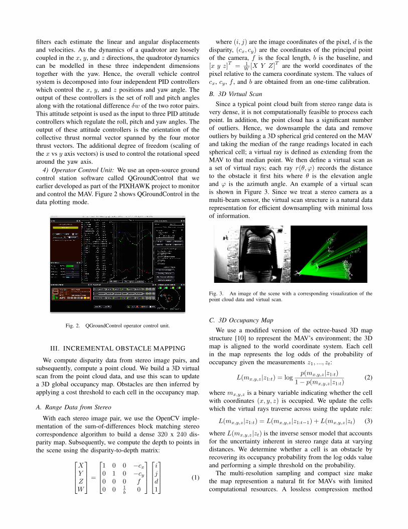
4) Operator Control Unit: We use an open-source groundcontrol station software called QGroundControl that weearlier developed as part of the PIXHAWK project to monitorand control the MAV. Figure 2 shows QGroundControl in thedata plotting mode.
Fig. 2. QGroundControl operator control unit.
III. INCREMENTAL OBSTACLE MAPPING
We compute disparity data from stereo image pairs, andsubsequently, compute a point cloud. We build a 3D virtualscan from the point cloud data, and use this scan to updatea 3D global occupancy map. Obstacles are then inferred byapplying a cost threshold to each cell in the occupancy map.
A. Range Data from Stereo
With each stereo image pair, we use the OpenCV imple-mentation of the sum-of-differences block matching stereocorrespondence algorithm to build a dense 320 x 240 dis-parity map. Subsequently, we compute the depth to points inthe scene using the disparity-to-depth matrix:
XYZW
=
1 0 0 −cx0 1 0 −cy0 0 0 f0 0 1
b 0
ijd1
(1)
where (i, j) are the image coordinates of the pixel, d is thedisparity, (cx, cy) are the coordinates of the principal pointof the camera, f is the focal length, b is the baseline, and[x y z]
T= 1
W [X Y Z]T are the world coordinates of the
pixel relative to the camera coordinate system. The values ofcx, cy , f , and b are obtained from an one-time calibration.
B. 3D Virtual Scan
Since a typical point cloud built from stereo range data isvery dense, it is not computationally feasible to process eachpoint. In addition, the point cloud has a significant numberof outliers. Hence, we downsample the data and removeoutliers by building a 3D spherical grid centered on the MAVand taking the median of the range readings located in eachspherical cell; a virtual ray is defined as extending from theMAV to that median point. We then define a virtual scan asa set of virtual rays; each ray r(θ, ϕ) records the distanceto the obstacle it first hits where θ is the elevation angleand ϕ is the azimuth angle. An example of a virtual scanis shown in Figure 3. Since we treat a stereo camera as amulti-beam sensor, the virtual scan structure is a natural datarepresentation for efficient downsampling with minimal lossof information.
Fig. 3. An image of the scene with a corresponding visualization of thepoint cloud data and virtual scan.
C. 3D Occupancy Map
We use a modified version of the octree-based 3D mapstructure [10] to represent the MAV’s environment; the 3Dmap is aligned to the world coordinate system. Each cellin the map represents the log odds of the probability ofoccupancy given the measurements z1, ..., zt:
L(mx,y,z|z1:t) = logp(mx,y,z|z1:t)
1− p(mx,y,z|z1:t)(2)
where mx,y,z is a binary variable indicating whether the cellwith coordinates (x, y, z) is occupied. We update the cellswhich the virtual rays traverse across using the update rule:
L(mx,y,z|z1:t) = L(mx,y,z|z1:t−1) + L(mx,y,z|zt) (3)
where L(mx,y,z|zt) is the inverse sensor model that accountsfor the uncertainty inherent in stereo range data at varyingdistances. We determine whether a cell is an obstacle byrecovering its occupancy probability from the log odds valueand performing a simple threshold on the probability.
The multi-resolution sampling and compact size makethe map represention a natural fit for MAVs with limitedcomputational resources. A lossless compression method

converts the map structure to a binary stream which is thentransmitted through the middleware to the path planner.
IV. INCREMENTAL PATH PLANNINGOur path planner searches for a path from the current
position of the MAV to an user-defined goal in 3D statespace (x, y, z). In this paper, we assume the MAV to be aholonomic vehicle, and hence, we do not include the roll-pitch-yaw in the state vector.
A. State LatticesWe use the state lattice concept [11] to decouple the
path planning problem into two distinct subproblems: vehiclemobility constraints and graph search. Within our state latticeof resolution 0.25m, a trajectory is discretized into a set ofmotion primitives which can be computed offline: one factorthat improves the efficiency of our path planner. Figure 4shows an example of a control set with 3D motion primitives.
Fig. 4. A control set with 26 motion primitives.
To determine the cost of a motion, we add the costs ofthe cells in the motion’s swath. A swath is the set of mapcells occupied by the MAV’s volume during the motion, andis precomputed for each motion primitive. This method ismore efficient than the widely-used method of simulating themotion to check which cells the MAV can safely traverse.
B. Graph SearchFor graph search, we use an anytime replanning search
algorithm called Anytime Dynamic A* (ADA*) [12]. At thebeginning, ADA* quickly computes a suboptimal path tothe goal, and continually improves the bound on the initialsolution based on available planning time. The heuristicinflation factor ε is the key; as shown in Figure 5, bydecreasing the inflation factor, the solution improves in termsof optimality but more states are explored.
Throughout the planning process, ADA* uses the samesearch tree. Furthermore, ADA* incrementally repairs thecurrent path in response to new obstacles that have justbeen observed. We use an admissible and consistent heuristicrequired by ADA* to guide the search: the cost of a path fromthe MAV to the goal given an obstacle map. We calculatethe path cost via Dial’s implementation of Dijkstra’s searchalgorithm [13].
V. IMPLEMENTATIONWe focus on autonomous flight at a fixed height in a lab
environment and discuss the details of the implementationused to achieve this autonomy.
(a) ε = 2.5 (b) ε = 1.0
Fig. 5. Any computed path can be decomposed into motion primitives.ADA* gradually improves the computed path over time by decreasing theheuristic inflation factor.
A. Pose Estimation
We estimate the MAV’s pose using either our artificialfeature-based localization software or a Vicon motion capturesystem. The feature-based localization [14] tracks uniqueARTK markers [15] with known positions on the groundusing downward-pointing cameras and estimates the poseof the camera; we apply a coordinate transform to find theMAV’s pose. In our Vicon motion capture system, strobeunits reflect infrared light off small retro-reflective markersattached to the MAV. Camera units use the reflectanceinformation to compute the image positions of the reflectedmarkers, and subsequently, the MAV’s pose.
B. Obstacle Mapping and Path Planning
We use a virtual scan resolution of 0.5◦ in our obstaclemapping. For path planning in a state lattice, we use a controlset with 16 motion primitives, all of which lie on the samez-plane. Every planned path maintains a minimum safetyclearance of 1m from obstacles.
Fig. 6. Our control set implementation contains 16 motion primitives.
On the MAV platform, both the obstacle mapping and pathplanning software run at approximately 10 Hz.
VI. EXPERIMENTS AND RESULTS
In one set of experiments, we placed an obstacle directlybetween the MAV and a designated goal. A snapshot ofthe obstacle mapping process is shown in Figure 7. TheMAV was able to plan a path around the obstacle as shownin Figure 8; blue cells denote obstacles, red cells denotelocations in close proximity to obstacles and which are notconsidered safe for the MAV, and yellow cells representstates that the MAV has yet to explore. For other cells, thegrayscale color indicates the cell cost; the more white the
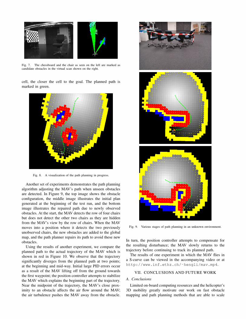
Fig. 7. The chessboard and the chair as seen on the left are marked ascandidate obstacles in the virtual scan shown on the right.
cell, the closer the cell to the goal. The planned path ismarked in green.
Fig. 8. A visualization of the path planning in progress.
Another set of experiments demonstrates the path planningalgorithm adjusting the MAV’s path when unseen obstaclesare detected. In Figure 9, the top image shows the obstacleconfiguration, the middle image illustrates the initial plangenerated at the beginning of the test run, and the bottomimage illustrates the repaired path due to newly observedobstacles. At the start, the MAV detects the row of four chairsbut does not detect the other two chairs as they are hiddenfrom the MAV’s view by the row of chairs. When the MAVmoves into a position where it detects the two previouslyunobserved chairs, the new obstacles are added to the globalmap, and the path planner repairs its path to avoid these newobstacles.
Using the results of another experiment, we compare theplanned path to the actual trajectory of the MAV which isshown in red in Figure 10. We observe that the trajectorysignificantly diverges from the planned path at two points;at the beginning and mid-way. Initial large PID errors occuras a result of the MAV lifting off from the ground towardsthe first waypoint; the position controller attempts to stabilizethe MAV which explains the beginning part of the trajectory.Near the midpoint of the trajectory, the MAV’s close prox-imity to an obstacle affects the air flow around the MAV;the air turbulence pushes the MAV away from the obstacle.
Fig. 9. Various stages of path planning in an unknown environment.
In turn, the position controller attempts to compensate forthe resulting disturbance; the MAV slowly returns to thetrajectory before continuing to track its planned path.
The results of one experiment in which the MAV flies ina S-curve can be viewed in the accompanying video or athttp://www.inf.ethz.ch/˜hengli/mav.mp4.
VII. CONCLUSIONS AND FUTURE WORK
A. Conclusions
Limited on-board computing resources and the helicopter’s3D mobility greatly motivate our work on fast obstaclemapping and path planning methods that are able to scale
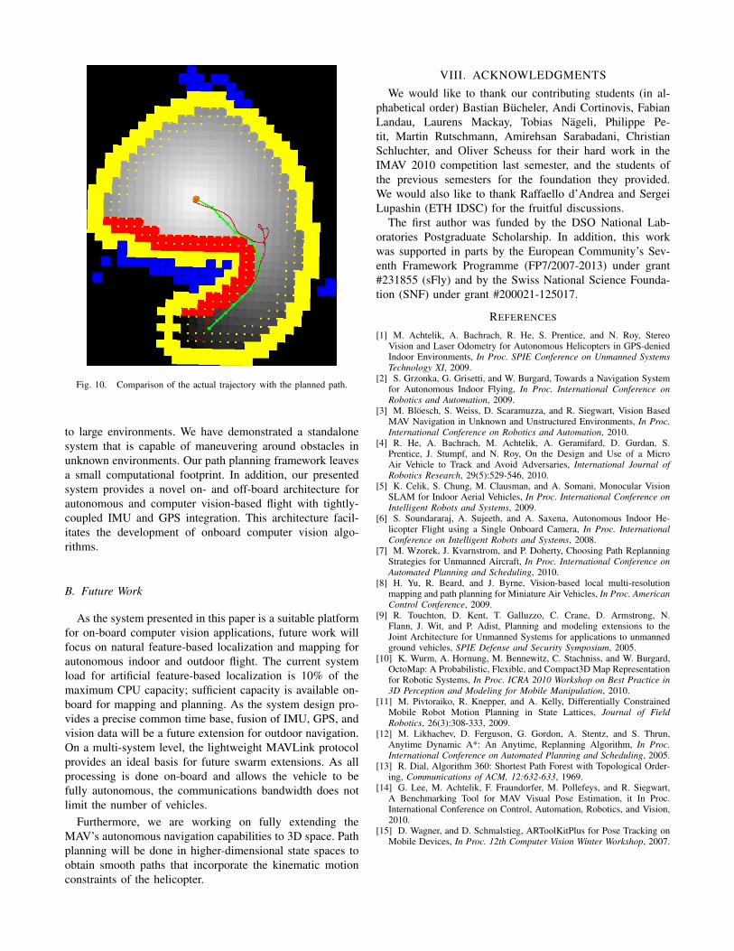
Fig. 10. Comparison of the actual trajectory with the planned path.
to large environments. We have demonstrated a standalonesystem that is capable of maneuvering around obstacles inunknown environments. Our path planning framework leavesa small computational footprint. In addition, our presentedsystem provides a novel on- and off-board architecture forautonomous and computer vision-based flight with tightly-coupled IMU and GPS integration. This architecture facil-itates the development of onboard computer vision algo-rithms.
B. Future Work
As the system presented in this paper is a suitable platformfor on-board computer vision applications, future work willfocus on natural feature-based localization and mapping forautonomous indoor and outdoor flight. The current systemload for artificial feature-based localization is 10% of themaximum CPU capacity; sufficient capacity is available on-board for mapping and planning. As the system design pro-vides a precise common time base, fusion of IMU, GPS, andvision data will be a future extension for outdoor navigation.On a multi-system level, the lightweight MAVLink protocolprovides an ideal basis for future swarm extensions. As allprocessing is done on-board and allows the vehicle to befully autonomous, the communications bandwidth does notlimit the number of vehicles.
Furthermore, we are working on fully extending theMAV’s autonomous navigation capabilities to 3D space. Pathplanning will be done in higher-dimensional state spaces toobtain smooth paths that incorporate the kinematic motionconstraints of the helicopter.
VIII. ACKNOWLEDGMENTS
We would like to thank our contributing students (in al-phabetical order) Bastian Bucheler, Andi Cortinovis, FabianLandau, Laurens Mackay, Tobias Nageli, Philippe Pe-tit, Martin Rutschmann, Amirehsan Sarabadani, ChristianSchluchter, and Oliver Scheuss for their hard work in theIMAV 2010 competition last semester, and the students ofthe previous semesters for the foundation they provided.We would also like to thank Raffaello d’Andrea and SergeiLupashin (ETH IDSC) for the fruitful discussions.
The first author was funded by the DSO National Lab-oratories Postgraduate Scholarship. In addition, this workwas supported in parts by the European Community’s Sev-enth Framework Programme (FP7/2007-2013) under grant#231855 (sFly) and by the Swiss National Science Founda-tion (SNF) under grant #200021-125017.
REFERENCES
[1] M. Achtelik, A. Bachrach, R. He, S. Prentice, and N. Roy, StereoVision and Laser Odometry for Autonomous Helicopters in GPS-deniedIndoor Environments, In Proc. SPIE Conference on Unmanned SystemsTechnology XI, 2009.
[2] S. Grzonka, G. Grisetti, and W. Burgard, Towards a Navigation Systemfor Autonomous Indoor Flying, In Proc. International Conference onRobotics and Automation, 2009.
[3] M. Bloesch, S. Weiss, D. Scaramuzza, and R. Siegwart, Vision BasedMAV Navigation in Unknown and Unstructured Environments, In Proc.International Conference on Robotics and Automation, 2010.
[4] R. He, A. Bachrach, M. Achtelik, A. Geramifard, D. Gurdan, S.Prentice, J. Stumpf, and N. Roy, On the Design and Use of a MicroAir Vehicle to Track and Avoid Adversaries, International Journal ofRobotics Research, 29(5):529-546, 2010.
[5] K. Celik, S. Chung, M. Clausman, and A. Somani, Monocular VisionSLAM for Indoor Aerial Vehicles, In Proc. International Conference onIntelligent Robots and Systems, 2009.
[6] S. Soundararaj, A. Sujeeth, and A. Saxena, Autonomous Indoor He-licopter Flight using a Single Onboard Camera, In Proc. InternationalConference on Intelligent Robots and Systems, 2008.
[7] M. Wzorek, J. Kvarnstrom, and P. Doherty, Choosing Path ReplanningStrategies for Unmanned Aircraft, In Proc. International Conference onAutomated Planning and Scheduling, 2010.
[8] H. Yu, R. Beard, and J. Byrne, Vision-based local multi-resolutionmapping and path planning for Miniature Air Vehicles, In Proc. AmericanControl Conference, 2009.
[9] R. Touchton, D. Kent, T. Galluzzo, C. Crane, D. Armstrong, N.Flann, J. Wit, and P. Adist, Planning and modeling extensions to theJoint Architecture for Unmanned Systems for applications to unmannedground vehicles, SPIE Defense and Security Symposium, 2005.
[10] K. Wurm, A. Hornung, M. Bennewitz, C. Stachniss, and W. Burgard,OctoMap: A Probabilistic, Flexible, and Compact3D Map Representationfor Robotic Systems, In Proc. ICRA 2010 Workshop on Best Practice in3D Perception and Modeling for Mobile Manipulation, 2010.
[11] M. Pivtoraiko, R. Knepper, and A. Kelly, Differentially ConstrainedMobile Robot Motion Planning in State Lattices, Journal of FieldRobotics, 26(3):308-333, 2009.
[12] M. Likhachev, D. Ferguson, G. Gordon, A. Stentz, and S. Thrun,Anytime Dynamic A*: An Anytime, Replanning Algorithm, In Proc.International Conference on Automated Planning and Scheduling, 2005.
[13] R. Dial, Algorithm 360: Shortest Path Forest with Topological Order-ing, Communications of ACM, 12:632-633, 1969.
[14] G. Lee, M. Achtelik, F. Fraundorfer, M. Pollefeys, and R. Siegwart,A Benchmarking Tool for MAV Visual Pose Estimation, it In Proc.International Conference on Control, Automation, Robotics, and Vision,2010.
[15] D. Wagner, and D. Schmalstieg, ARToolKitPlus for Pose Tracking onMobile Devices, In Proc. 12th Computer Vision Winter Workshop, 2007.