autonomous mission management for uavs using soar intelligent agents
TRANSCRIPT
This article was downloaded by: [New York University]On: 05 October 2014, At: 10:01Publisher: Taylor & FrancisInforma Ltd Registered in England and Wales Registered Number: 1072954 Registered office: Mortimer House,37-41 Mortimer Street, London W1T 3JH, UK
International Journal of Systems SciencePublication details, including instructions for authors and subscription information:http://www.tandfonline.com/loi/tsys20
Autonomous mission management for UAVs using soarintelligent agentsPaolo Gunetti a , Haydn Thompson a & Tony Dodd aa Department of Automatic Control and Systems Engineering , University of Sheffield ,Sheffield , UKPublished online: 08 Nov 2011.
To cite this article: Paolo Gunetti , Haydn Thompson & Tony Dodd (2013) Autonomous mission management for UAVs usingsoar intelligent agents, International Journal of Systems Science, 44:5, 831-852, DOI: 10.1080/00207721.2011.626902
To link to this article: http://dx.doi.org/10.1080/00207721.2011.626902
PLEASE SCROLL DOWN FOR ARTICLE
Taylor & Francis makes every effort to ensure the accuracy of all the information (the “Content”) containedin the publications on our platform. However, Taylor & Francis, our agents, and our licensors make norepresentations or warranties whatsoever as to the accuracy, completeness, or suitability for any purpose of theContent. Any opinions and views expressed in this publication are the opinions and views of the authors, andare not the views of or endorsed by Taylor & Francis. The accuracy of the Content should not be relied upon andshould be independently verified with primary sources of information. Taylor and Francis shall not be liable forany losses, actions, claims, proceedings, demands, costs, expenses, damages, and other liabilities whatsoeveror howsoever caused arising directly or indirectly in connection with, in relation to or arising out of the use ofthe Content.
This article may be used for research, teaching, and private study purposes. Any substantial or systematicreproduction, redistribution, reselling, loan, sub-licensing, systematic supply, or distribution in anyform to anyone is expressly forbidden. Terms & Conditions of access and use can be found at http://www.tandfonline.com/page/terms-and-conditions
International Journal of Systems ScienceVol. 44, No. 5, May 2013, 831–852
Autonomous mission management for UAVs using soar intelligent agents
Paolo Gunetti*, Haydn Thompson and Tony Dodd
Department of Automatic Control and Systems Engineering, University of Sheffield, Sheffield, UK
(Received 29 November 2010; final version received 8 September 2011)
State-of-the-art unmanned aerial vehicles (UAVs) are typically able to autonomously execute a pre-plannedmission. However, UAVs usually fly in a very dynamic environment which requires dynamic changes to the flightplan; this mission management activity is usually tasked to human supervision. Within this article, a softwaresystem that autonomously accomplishes the mission management task for a UAV will be proposed. The system isbased on a set of theoretical concepts which allow the description of a flight plan and implemented using acombination of Soar intelligent agents and traditional control techniques. The system is capable of automaticallygenerating and then executing an entire flight plan after being assigned a set of objectives. This article thoroughlydescribes all system components and then presents the results of tests that were executed using a realisticsimulation environment.
Keywords: autonomous UAV; intelligent agents; multi-layer architecture
1. Introduction
Unmanned aerial vehicles (UAVs) have relatively
become common in aviation during the last two
decades. Military usage remains the dominant appli-cation field for UAVs; however, civilian applications
are starting to be developed. UAVs present obviousadvantages over manned vehicles (reduced operating
costs, expendability and improved performance)(Schaefer et al. 2001) and it is expected that their use
will continue to increase, finding its way into new
application fields (DeGarmo and Nelson 2004).Current UAVs are widely different from a control
point of view: they range from remotely controlled
drones to highly autonomous aircraft that are capableof carrying out a pre-planned mission on their own
(Miller et al. 2005), without the need of direct humancontrol. In fact, the increase of autonomy is one of the
most recognisable trends in the UAV industry. This is
driven by three main objectives:
. control of UAVs by personnel without extensivepilot training; this is desirable as it could
potentially greatly reduce operating costs and
thus open up previously unavailable marketopportunities, such as environmental
monitoring. control of multiple UAVs by a single user; this is
desirable particularly in the military field, where
missions usually have severe time constraints
and can be better accomplished by teams ofUAVs rather than single UAVs
. improvement of safety characteristics; civil useof UAVs still suffers from a regulatory gap(Crum, Homan, and Bortner 2004) and thedifficulty of ensuring safety when the pilot is noton-board (the pilot might be incapable of takingaction, but also may lack appropriate situationalawareness)
These issues can be summarised by saying thatcurrent generation UAVs lack autonomous missionmanagement capabilities: while they can autonomouslyexecute a pre-planned mission, the flight plan (orchoice of possible flight plans) has to be prepared by apilot (or operator). Also, UAVs usually fly in verydynamic environments; thus, supervision is constantlyneeded in order to update the flight plan with newinformation that becomes available as the mission isexecuted.
An autonomous mission management systemshould be capable of (UAV Task Force 2004):
. generating a full flight plan, once given a set ofobjectives by a user
. taking into account UAV capabilities and status,environment information and target informa-tion during flight plan generation
. updating the flight plan as the mission is executedand situational awareness changes (for example,
*Corresponding author. Email: [email protected]
ISSN 0020–7721 print/ISSN 1464–5319 online
� 2013 Taylor & Francis
http://dx.doi.org/10.1080/00207721.2011.626902
http://www.tandfonline.com
Dow
nloa
ded
by [
New
Yor
k U
nive
rsity
] at
10:
01 0
5 O
ctob
er 2
014
if the UAV is damaged or if new environmentalor target information is available)
Identifying the autonomy level of a UAV is nottrivial; a paper by Clough (2002) has become the de-facto standard on the subject. In this article, the authordefines 11 different autonomy levels, ranging fromlevels 0 (remotely controlled vehicle) to 10 (fullyautonomous, meaning the capability to make decisionswithout supervision). The breadth of autonomouscapabilities described is very large and in fact, eachlevel of autonomy brings significant additions on theprevious one. A remotely controlled UAV is classifiedat level 0, which still assumes an appropriate suite ofsensors, actuators and communication devices. Level 1autonomy is defined as the ability to execute a pre-planned mission, and this means that a whole set ofcapabilities is being added on top of level 0 autonomy,and in particular flight control and navigationcapabilities. Levels 2–5 focus on the development ofsingle-UAV capabilities, most importantly healthmanagement, trajectory optimisation and contingencymanagement; the type of autonomy reached withinthese levels allows a UAV to perform better inuncertain and dynamic environments, since the UAVcan adapt its flight plan during the mission in order toactively respond to changes. Levels 6 to 10 are fullydedicated to the integration of a single UAV within ateam of UAVs, which can share sensor informationand cooperate to reach overall mission objectives.
More recent papers expand on this framework,analysing specific aspects in greater detail. In the studyof Sholes (2007), it is possible to see that the currentgeneration of UAVs in operation ranks very low in theframework. Furthermore, progress in the autonomyfield has been very slow. For example, in 1985, thePioneer UAV provided capabilities that placed it alittle below level 1 (execute pre-planned mission), whilethe Predator UAV in 1996 and the Global Hawk in2004 can be placed between levels 1 and 2 (changeablemission, meaning that the UAV can autonomouslyswitch between several pre-determined flight plans).In the study of Suresh and Ghose (2009), the issues ofinformation flow and communication are placedwithin the context of UAV autonomy levels; thepapers details how communication between the UAVand the human operator is critical at low autonomylevels, while inter-UAV communication becomes prev-alent at higher autonomy levels.
A significant number of software approaches andarchitectures that could be applied to the improvementof vehicle autonomy are available. Among these,notable examples include ACT-R, Soar and JACK;these architectures originate from cognitive sciencestudies and have found successful application in
robotics (Laird and Rosenbloom 1990; Bugajska,Schultz, Trafton, Taylor, and Mintz 2002; Karim,Heinze, and Dunn 2004). A paper by Long, Hanford,Janrathitikarn, Sinsley, and Miller (2007) reviewsavailable software systems and compares their capa-bilities; the paper highlights how most of them aredifficult to use, and that there is a lack of standards fortheir comparison. Furthermore, it can be noted thatmost of these approaches are robotics-driven ratherthan UAV-driven, and therefore usually favouradvanced functionality over usability. In many cases,the computing power required by such systems istoo large to guarantee real-time operation, especiallywith the limited computing resources (relatively toground systems) that can be expected to be availableon a UAV.
Many studies (Li et al. 2002; Cummings, Bruni,Mercier, and Mitchell 2007) deal with control ofmultiple UAVs, mostly focusing on the distributionof tasks among teams of UAVs (possibly with asym-metric capabilities). The difficulty of cooperativecommand and control is exacerbated by possiblecommunication issues, and the use of intelligentsoftware agents has been proposed as a solution(Sujit and Ghose 2009). Literature regarding missionmanagement for a single UAV is, however, very scarce.In Veres, Molnar, Lincoln, and Morice (2010), severalautonomy-focused projects are reviewed; the authorsnote that, at present, there is no unified attempt todevelop standards in this field, thus resulting in non-coordinated research efforts and in difficulties regard-ing certification of such technology. The possibility ofcertification is critical for the development of safety-critical systems such as UAVs, and intelligent agenttechnology is proposed as a possible approach thatcould allow the definition of a clearer path towardscertification.
An interesting approach in this sense is presentedby Heinze and Karim in several papers (Karim et al.2004; Lucas et al. 2004; Karim and Heinze 2005): inthis study, a cognitive system is used to provide thereasoning capability needed by a mission managementsystem. This system is implemented using the JACKintelligent agent language, and has demonstrated alimited set of autonomy-related capabilities duringactual flight tests.
In this article, a similar system will be proposed,in which a cognitive architecture is used to provide thereasoning capability needed for mission management.The system is based on the Soar agent architecture;this choice will be motivated in Section 2. Compared tothe work by Heinze and Karim, the system incorpo-rates broader functionality; while their work is focusedon bringing limited decision-making capability inthe occurrence of in-flight issues, with a strong
832 P. Gunetti et al.
Dow
nloa
ded
by [
New
Yor
k U
nive
rsity
] at
10:
01 0
5 O
ctob
er 2
014
focus on actual implementation and flight testing;the aim of our proposed system will be to developa software system with the capability to fully developa flight plan, execute it and then update it duringthe execution in response to newly availableknowledge.
While designing and implementing this system,three main driving concepts were kept in mind soas to bring significant improvements over earlierexperiences:
. the user should need to interact with the UAVsystem only at the highest level of control, byassigning mission objectives to it; no furthersupervision should be expected
. the system should be designed for low-costimplementation using common-off-the-shelfhardware, with a particular focus on real-timecapabilities and certifiability
. the system should show a sufficient degree ofintelligence in deriving flight plans that are notonly viable but also optimised, without impact-ing negatively real-time capabilities andcertifiability
With respect to the UAV autonomy levels definedin Clough (2002), the aim of this system is to achieveautonomy between levels four and five. The higherautonomy levels, related to multi-UAV cooperationand coordination, are certainly desirable for certainapplications, and particularly in the military fieldwhich currently represents the large majority of UAVapplications. However, this study was focused onsingle UAVs for two precise reasons: first, becausethe achievement of lower levels of autonomy is a pre-requisite for achievement of the higher levels; second,because not all applications will require multiplecooperating UAVs. While the civilian use of UAVs isnot currently widespread, it can certainly be expectedto expand in the near future, once safety concerns andregulatory issues are dealt with; possible applicationsrange from surveillance to environmental monitoringand communications relay (Wegener et al. 2004), andin many cases, a single UAV would be sufficient. Thedeciding factor for civilian applications will be costeffectiveness, and low cost is part of the main drivingconcepts for the entire project.
It is to be noted that some functionality needed toachieve level four of autonomy, such as airframe healthmanagement and communications with externalagents, will not be treated directly in this article;rather than focusing on the development of suchfunctionality, a methodology for incorporating suchinformation into an autonomous flight plan generationprocess will be detailed. Throughout the article, theavailability of specific underlying layers of
functionality (such as airframe health management)will be assumed, and a description of how the softwarearchitecture integrates this information into the plangeneration process will be given. The exception to thisis represented by the UAV flight control and naviga-tion systems, which can also be considered as anunderlying layer but will be thoroughly treated; theintegration of these systems within the architectureprovides an example of how other functionality mightbe integrated.
The project’s driving concepts place significantrestrictions on the type of algorithms that can be usedwithin the system. For example, genetic algorithmswould provide very good flight plan optimisationcapabilities; however, they have to be excluded becausethey would not satisfy real-time requirements. It is alsoto be noted that, because minimal human supervisionis a goal, hybrid control techniques such as slidingautonomy (Heger and Singh 2006) were not consid-ered; these are also discouraged by the nature of UAVcontrol (as opposed to robot control), where appro-priate situational awareness is an issue even for anexperienced human pilot. In fact, the system is imple-mented using the Soar intelligent agent architecture(thus, the name SAMMS, Soar-based autonomousmission management system); the reason behind thischoice is described in Section 2. Integration withtraditional control techniques allows execution of theflight plans derived by the mission managementalgorithms. SAMMS is designed as a low-cost archi-tecture for the control software of a fully autonomousUAV, which should be able to entirely perform amission once given a set of objectives by a user.SAMMS generates a flight plan that takes into accountUAV status and environment information, then exe-cutes the generated flight plan and dynamicallyupdates it as new information is available.
Through simulation tests, this article aims atdemonstrating that the SAMMS architecture is viableand possesses highly desirable characteristics: fullautonomy, replanning ability, real-time operation andpotential for certification. Theoretical work is alsopresented, outlining a novel way to computationallydescribe a UAV mission. The article is divided into fivesections. In Section 2, the theoretical base for SAMMSwill be presented; the main abstractions used duringdevelopment will be outlined, and the chosen systemarchitecture described. In Section 3, the softwarecomponents (including three different Soar agentsand additional control software) will be illustrated indetail. In Section 4, the architecture will be tested usinga realistic simulation environment; the environment isdescribed and results are presented. Finally, Section 5will draw conclusions regarding the work and proposepossible future work.
International Journal of Systems Science 833
Dow
nloa
ded
by [
New
Yor
k U
nive
rsity
] at
10:
01 0
5 O
ctob
er 2
014
2. Theoretical concepts and architecture description
In the system presented in this article (SAMMS),
reasoning and planning capabilities are provided bySoar intelligent agents. Intelligent agents (IAs) repre-
sent a new paradigm for software engineering and werefirst introduced in the early 1990s to improve the
flexibility of software systems (Jennings andWooldridge 1998; Wooldridge 1999). The agent-
based approach to computing is highly theoreticaland in fact, spans such broad concepts that it is
difficult to univocally define an intelligent agent;however, this approach has found many applications
and currently represents the state-of-the-art for specificapplications, such as internet search engines and air
traffic control.IA-based systems have brought significant
advances in cognitive studies, bringing the possibility
to mimic on a computer the thought patterns of ahuman brain (while neural networks do the same, they
are usually ‘black-box’ systems whose capabilitiescannot be fully understood). Several architectures for
IA-based systems have been proposed, including thepreviously mentioned Soar and JACK. In Long et al.
(2007), many of these systems are discussed. The Soararchitecture was chosen for the development of
SAMMS for several reasons:
. it is a cognitive modelling tool which allows to
replicate human thought processes through theuse of symbolic AI techniques, thus providing
very high potential in developing intelligentcapabilities
. it is proven to be capable to deal with verycomplex problem spaces while maintaining real-
time operation. it provides a good I/O interface, both between
separate agents and with external components. its core is written in the Cþþ language (on the
contrary, the aforementioned JACK package isbased on Java), thus providing an easier path
towards certification. it is a fully open-source project
Soar is the computational implementation of acognitive architecture which was developed at Carnegie
Mellon University in the 1980s and has since beenmaintained by the University of Michigan (Laird,
Newell, and Rosenbloom 1987; Soar Technology Inc2002; Lehman, Laird, and Rosenbloom 2006). It
provides a robust architecture for building complexhuman behaviour models and intelligent systems that
use large amounts of knowledge. At a high level of
abstraction, it uses a standard information processingmodel including a processor, memory store and periph-
eral components for interaction with the outside world.
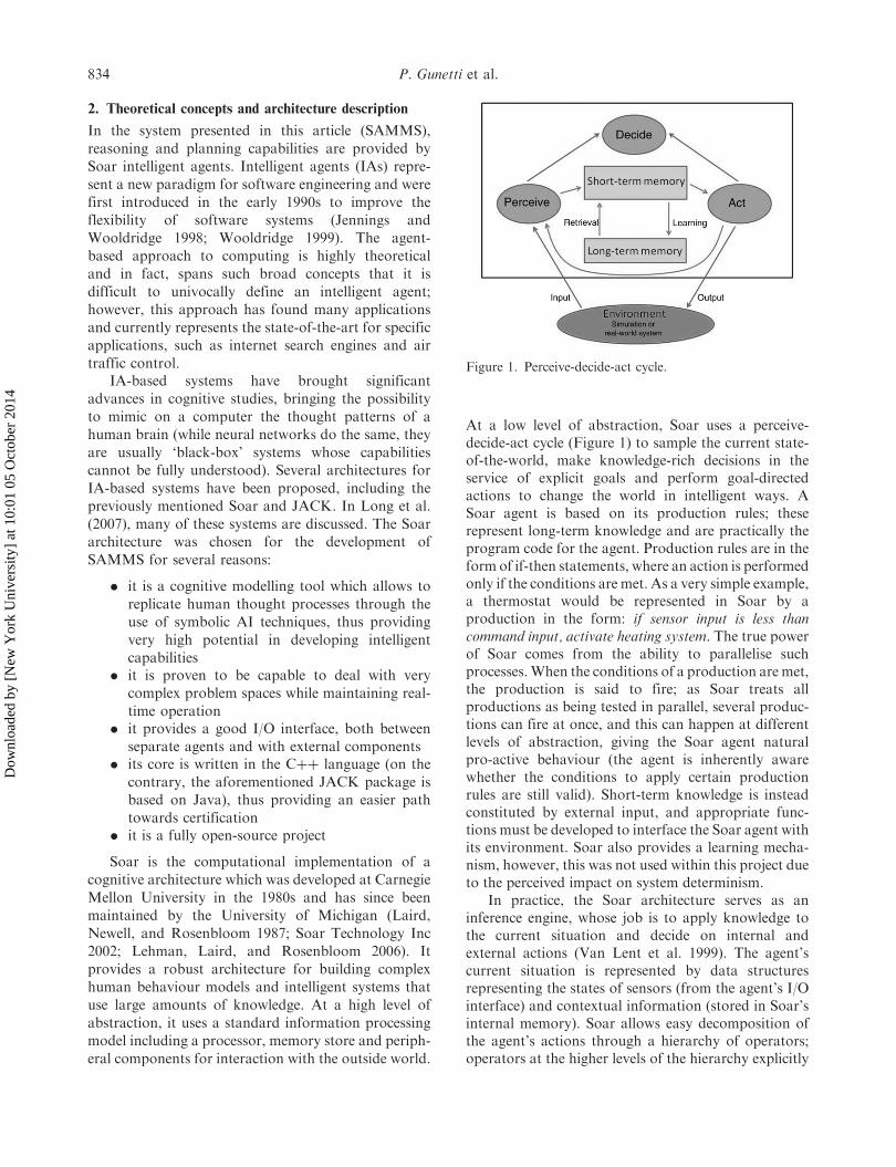
At a low level of abstraction, Soar uses a perceive-decide-act cycle (Figure 1) to sample the current state-of-the-world, make knowledge-rich decisions in theservice of explicit goals and perform goal-directedactions to change the world in intelligent ways. ASoar agent is based on its production rules; theserepresent long-term knowledge and are practically theprogram code for the agent. Production rules are in theform of if-then statements, where an action is performedonly if the conditions are met. As a very simple example,a thermostat would be represented in Soar by aproduction in the form: if sensor input is less thancommand input, activate heating system. The true powerof Soar comes from the ability to parallelise suchprocesses.When the conditions of a production are met,the production is said to fire; as Soar treats allproductions as being tested in parallel, several produc-tions can fire at once, and this can happen at differentlevels of abstraction, giving the Soar agent naturalpro-active behaviour (the agent is inherently awarewhether the conditions to apply certain productionrules are still valid). Short-term knowledge is insteadconstituted by external input, and appropriate func-tions must be developed to interface the Soar agent withits environment. Soar also provides a learning mecha-nism, however, this was not used within this project dueto the perceived impact on system determinism.
In practice, the Soar architecture serves as aninference engine, whose job is to apply knowledge tothe current situation and decide on internal andexternal actions (Van Lent et al. 1999). The agent’scurrent situation is represented by data structuresrepresenting the states of sensors (from the agent’s I/Ointerface) and contextual information (stored in Soar’sinternal memory). Soar allows easy decomposition ofthe agent’s actions through a hierarchy of operators;operators at the higher levels of the hierarchy explicitly
Figure 1. Perceive-decide-act cycle.
834 P. Gunetti et al.
Dow
nloa
ded
by [
New
Yor
k U
nive
rsity
] at
10:
01 0
5 O
ctob
er 2
014
represent the agent’s goals, while the lower leveloperators represent sub-steps and atomic actions usedto achieve these goals. Soar selects and executes theoperators relevant to the current situation that specifyexternal actions, which are applied to the environmentthrough the I/O interface, and internal actions, such aschanges to the agent’s internal goals. This process isconstantly happening during the perceive-decide-actcycle; the agent will gather sensor information, applylong-term knowledge to it in order to analyse thesituation and make decisions, and then act onthe environment so as to pursue both long-term andthe sub-goals that are internally declared whilepursuing long-term ones.
To give a clearer idea of what a Soar agent does, letus consider this example. A Soar agent is used to act asa thermostat; it receives a temperature sensor readingand a desired temperature value as input and it sends abinary on/off command as output. In its simplest form,the agent would need two operators, which can beoutlined by the following pseudo-code:
. if sensor temp is less than (desired temp – 2), thenset heating on
. if sensor temp is more than (desired tempþ 2),then set heating off
It is then possible to add layers of complexity uponthis; for example, a light sensor might be used to avoidactivation during the night, leading to an operator suchas: if sensor temp is less than (desired temp – 2) and lightis detected, then set heating on. Also, a fuel sensormight be used to save fuel when the fuel level is low;this can be done with a third operator (if sensor temp ismore than (desired temp þ 1), then set heating off) anda preference rule to choose between the second andthird operators: if fuel level is lower than threshold,prefer third operator, else prefer second operator. Soarallows for the combination and organisation in hier-archies of large numbers of such rules, lead to verycomplex agent behaviour. For further details regardingthe Soar architecture, please refer to Newell (1980),Laird et al. (1987), Laird and Rosenbloom (1990) andNewell (1990).
The Soar architecture has been used in severalrobotics and artificial intelligence projects. Earlyapplications include Robo-Soar and Hero-Soar, twovery task-specific robots that were controlled usingSoar agents (Laird and Rosenbloom 1990). TacAir-Soar is a rule-based system that simulates the behav-iour of a military plane pilot and is used for large-scaledistributed military simulations (Jones et al. 1999).Soar has also been used as a tool for officer decision-making training in operations-other-than-war simula-tions (Kalus and Hirst 1998). Finally, the HexCrawlerrobot developed at Penn State University uses the Soar
architecture for high-level robot control (Hanford,Janrathitikarn, and Long 2008; Janrathitikarn andLong 2008).
In practical terms, a Soar agent is a Cþþ class, andappropriate I/O functions have to be developed inorder to interface it with its environment. Since theobjective is to combine Soar agents with other controltechniques, we chose to integrate them withMatlab\Simulink, which is the most commonly usedsoftware package in control systems design. Thisallows seamless integration of the control algorithms,once the Soar\Simulink interface is set up, and alsoprovides a simulation environment which is indispen-sible in testing the system.
This approach (based on the integration of Soaragents within Simulink) was initially applied in thedevelopment of a Health Management system for Gas-Turbine Engines (Gunetti, Mills, and Thompson 2008;Gunetti and Thompson 2008, 2010). During this study,the feasibility of the approach was demonstrated, andin particular two ideas were developed: the implemen-tation of Soar agents as Simulink S-Functions, and theuse of multiple interfaced Soar agents in a Simulinkenvironment. However, the use of this technology didnot bring significant advantages over ‘conventional’technology with similar functionality, due to a limitedproblem space and severe constraints. The sameapproach was then used on the larger problem spaceof autonomous UAV mission management. Earlyresults are presented in a separate paper (Gunetti,Dodd, and Thompson 2010).
2.1. Theoretical concepts
An autonomous mission management system needs aset of abstractions allowing clear definition of allphases of a flight plan. Furthermore, these abstractionsshould allow the definition of several types of mission,ranging from a typical transport mission (navigatefrom points A to B, likely through a set of waypoints)to complex military-type missions that involve navi-gating to objectives where specific actions have to beperformed. Four main abstractions have been identi-fied during this study: the Objective, the Action, theFlight Plan and the Entity.
The Objective is the abstraction through which aUser interacts with SAMMS: when assigning a missionto a UAV, a User will basically give a list of Objectives.An Objective represents a very high-level task forthe UAV, defining a significant part of a mission. Thetypes of Objectives can greatly vary depending on thespecific type of UAV, but at present five generic typeshave been defined: analyse target (go to a position togather data on a specific target using payload sensors),
International Journal of Systems Science 835
Dow
nloa
ded
by [
New
Yor
k U
nive
rsity
] at
10:
01 0
5 O
ctob
er 2
014
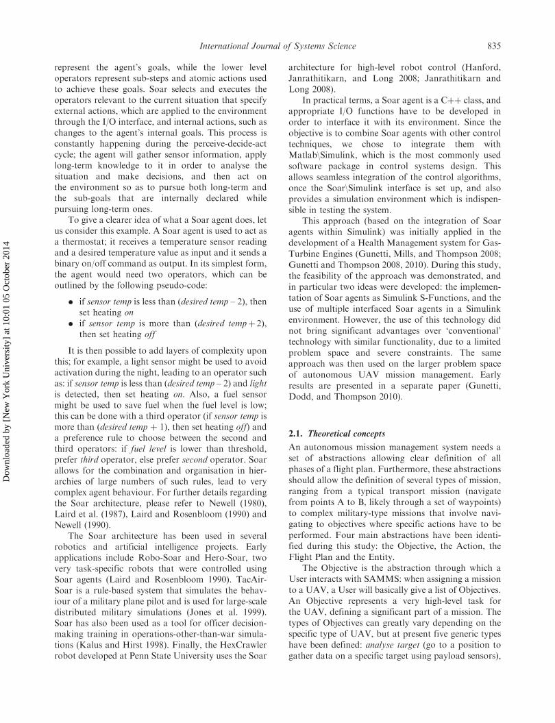
attack target (deliver a weapon payload on a specifictarget), orbit position (circle about a position for aspecified time, for example, to act as communicationsrelay), search area (patrol an area using standardpatterns in order to identify targets) and transit (travelto a destination airport and land there). The ObjectiveI/O object has a total of 11 properties that can fullydefine any type of Objective previously described.Table 1 provides these variables (note that someproperties are described by multiple variables).
The Action is an abstraction which still represents ahigh-level task, but is the finest subdivision which isrelevant from a mission management point of view. Ingeneral, an Objective will always correspond to two ormore Actions. About 12 types of Action have beenidentified as necessary to fully describe a flight planthat accomplishes Objective of the types earlierdescribed (Table 2). The Action I/O object consists of11 properties that together fully describe it (Table 3).Using these definitions, a Flight Plan is a numberedsequence of Actions that fully describes a mission. TheUAV will then be able to accomplish a mission byexecuting Actions in the expected order.
The fourth and final abstraction is the Entity. TheEntity represents any external factor that may influ-ence the generation of the Flight Plan. Entities includetargets of various types (buildings, vehicles), but alsoknown threats (hostile presences, bad weather areas,etc.) and constraints (geography, Air Traffic Controlzones). The Entity I/O object consists of eight variablesthat describe its nature, its position and its behaviouramong other things (Table 4). While Objectives are aUser Input, Entities are expected to be receivedautomatically from an information gathering system(in military terms, the ‘Battlefield Network’).
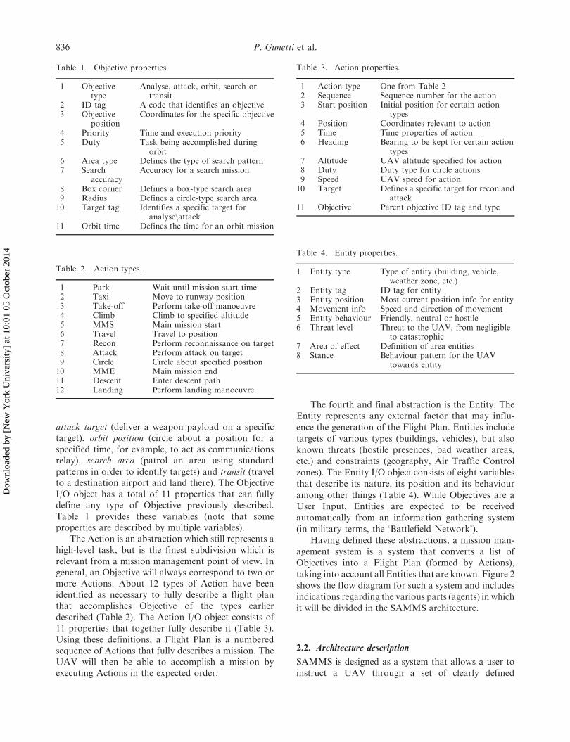
Having defined these abstractions, a mission man-agement system is a system that converts a list ofObjectives into a Flight Plan (formed by Actions),taking into account all Entities that are known. Figure 2shows the flow diagram for such a system and includesindications regarding the various parts (agents) in whichit will be divided in the SAMMS architecture.
2.2. Architecture description
SAMMS is designed as a system that allows a user toinstruct a UAV through a set of clearly defined
Table 1. Objective properties.
1 Objectivetype
Analyse, attack, orbit, search ortransit
2 ID tag A code that identifies an objective3 Objective
positionCoordinates for the specific objective
4 Priority Time and execution priority5 Duty Task being accomplished during
orbit6 Area type Defines the type of search pattern7 Search
accuracyAccuracy for a search mission
8 Box corner Defines a box-type search area9 Radius Defines a circle-type search area10 Target tag Identifies a specific target for
analyse\attack11 Orbit time Defines the time for an orbit mission
Table 3. Action properties.
1 Action type One from Table 22 Sequence Sequence number for the action3 Start position Initial position for certain action
types4 Position Coordinates relevant to action5 Time Time properties of action6 Heading Bearing to be kept for certain action
types7 Altitude UAV altitude specified for action8 Duty Duty type for circle actions9 Speed UAV speed for action10 Target Defines a specific target for recon and
attack11 Objective Parent objective ID tag and type
Table 2. Action types.
1 Park Wait until mission start time2 Taxi Move to runway position3 Take-off Perform take-off manoeuvre4 Climb Climb to specified altitude5 MMS Main mission start6 Travel Travel to position7 Recon Perform reconnaissance on target8 Attack Perform attack on target9 Circle Circle about specified position10 MME Main mission end11 Descent Enter descent path12 Landing Perform landing manoeuvre
Table 4. Entity properties.
1 Entity type Type of entity (building, vehicle,weather zone, etc.)
2 Entity tag ID tag for entity3 Entity position Most current position info for entity4 Movement info Speed and direction of movement5 Entity behaviour Friendly, neutral or hostile6 Threat level Threat to the UAV, from negligible
to catastrophic7 Area of effect Definition of area entities8 Stance Behaviour pattern for the UAV
towards entity
836 P. Gunetti et al.
Dow
nloa
ded
by [
New
Yor
k U
nive
rsity
] at
10:
01 0
5 O
ctob
er 2
014

Objectives and then leave all details of missionexecution to the autonomous system. No furthersupervision is expected, so the system should be ableto optimise the Flight Plan according to knowninfluencing factors (usually defined as Entities) andupdate it when new situational awareness is available.Since SAMMS is not based around a standardised setof abstractions (as no such thing exists), it should notonly perform the mission management activity, butalso be able to convert it into actual flight instructions.
In order to achieve this functionality, a multi-agentsystem has been devised. This is based around threeinteracting Soar agents that are implemented in aSimulink environment. The three agents are thePlanner Agent, the Execution Agent and the MissionManager Agent (MMA). The Simulink environmentprovides supporting functionality such as a Userinterface, real world sensory input (including on-boardsensors and external data), and a set of Simulink
functions that perform lower level tasks, such asAutopilot and Payload Management algorithms.Figure 3 schematically describes the architecture.While detailed information about implementation ofeach agent is provided in Section 3. It is important hereto describe what tasks each agent must perform.
The Planner Agent is tasked with receivingObjectives as input from a User and then fusing themwith real world information (available as Entityobjects) in order to obtain a full Flight Plan (aspreviously defined, a sequence of Actions). A first planis generated at the start of a mission, this plan is thenupdated when situational awareness changes. The planis updated by generating an entirely new plan thattakes into account parts of the former plan that havealready been executed. The Planner Agent decides theorder in which Objectives are sequenced, and includesseveral algorithms that allow improving the FlightPlan in several ways, such as avoiding dangerous areas,increasing flight speed in order to reach a target beforea specified time, or decreasing flight speed in order tosave fuel so that all parts of the mission can beaccomplished.
Generation of a new plan is triggered by an externalcomponent, called the New Plan Trigger; this is toensure a better balance between pro-active and reactivebehaviours. Reactive behaviour can be represented bythe extreme case where any change in sensory inputdetermines a replanning event; pro-active behaviourinstead is represented by the extreme case where theoriginal flight plan is never updated. None of the casesis desirable and to balance the two behaviours, a point-based system has been implemented; changes in thecurrent situation are graded using a point scheme and anew plan is generated when the total of pointsovercomes a specified threshold. Some situationalchanges are graded at zero points (no effect onreplanning), some have a low number of points (theywill not trigger replanning on their own), and some areassigned a number of points higher than the threshold(they will trigger replanning on their own).
The Execution Agent takes as input the Flight Planand then executes it Action by Action. It basically actsas a transition layer between the Planner and low-levelcontrols. As the mission is executed, it chooses whatAction is to be performed and then, fusing theinformation contained within the Action with real-time sensor data (Global Positioning System (GPS),attitude, airspeed, etc.), sends commands to the lowerlevel control systems, namely the Autopilot and thePayload Management System.
The MMA is tasked with dealing with contingen-cies in the Flight Plan. It is very important for theintelligence of the overall system, since it has theauthority to change the Objectives (that are otherwise
Figure 3. Architecture overview.
Figure 2. SAMMS flow diagram.
International Journal of Systems Science 837
Dow
nloa
ded
by [
New
Yor
k U
nive
rsity
] at
10:
01 0
5 O
ctob
er 2
014
exclusively defined by the user) and to add new ones.For example, it can cancel a secondary Objective thatis close to a newly detected threat, or change theparameters of a Search mission if a minor fault placesstricter endurance limits on the UAV, or, finally, takeadvantage of targets of opportunity. This kind ofautonomy is needed in order to really make ‘intelligent’decisions, however finding the balance betweenexcessive autonomy and intelligent behaviour is adifficult task.
The agents are complemented by a set of functionsthat use more traditional control techniques:
. the New Plan Trigger function, which monitorsall inputs to the system and compares them withthe situation recorded when the last Flight Planwas generated, in order to trigger the generationof a new flight plan only when truly needed (thisseparately triggers both the Planner and theMMAs)
. the Autopilot function, which consists of a set ofstandard autopilots that allow control of theflight path of the UAV during the variousmission phases, thus implementing commandsfrom the Execution Agent
. the Payload Management function, which trans-lates generic payload commands from theExecution agent to actual controls for thepayload actuators
Completing the loop is the simulation environment,which is modelled in Simulink and receives input fromthe low-level functions and provides feedback as realworld sensor information.
To clarify the relationship between the agents andhow they interact between themselves and with theenvironment, let us consider the following example.The human operator of the UAV wants a mission to beperformed; this can be profiled using two separateObjectives (as defined earlier in this section). TheObjectives are sent to SAMMS, which also has an on-board sensory system and a data-link that providesinformation not available to on-board sensors (the‘battlefield network’, in military terms). The PlannerAgent fuses the Objectives and the other availableinformation into a flight plan. The mission can thenbegin, being carried out by the Execution Agent, whichis feeding commands directly to the low-level controlalgorithms (autopilot and payload management). Soonafter take-off, a new threat is detected and the plan isupdated so as to avoid entering the threat area ofeffect. The first Objective is accomplished but whileflying towards the second Objective, a fuel leak isdetected. The Planner updates the flight plan with newestimates showing that because of this, the UAV willnot have sufficient fuel to complete the second
Objective and return to base; thus the MMA intervenesand cancels the Objective. The Planner then updatesthe flight plan, which sees the UAV reverting backto base.
3. Software description
In this section, the software components of SAMMSare described. This includes the three Soar agents andsupporting software such as the autopilots. Thedescription will focus on actual implementation, asthe function performed by each component has beenoutlined in Section 2.
3.1. Planner agent
As previously stated, the Planner Agent’s task is toconvert a list of Objectives into a Flight Plan (anumbered sequence of Actions), taking into account allknown information (and Entities in particular).
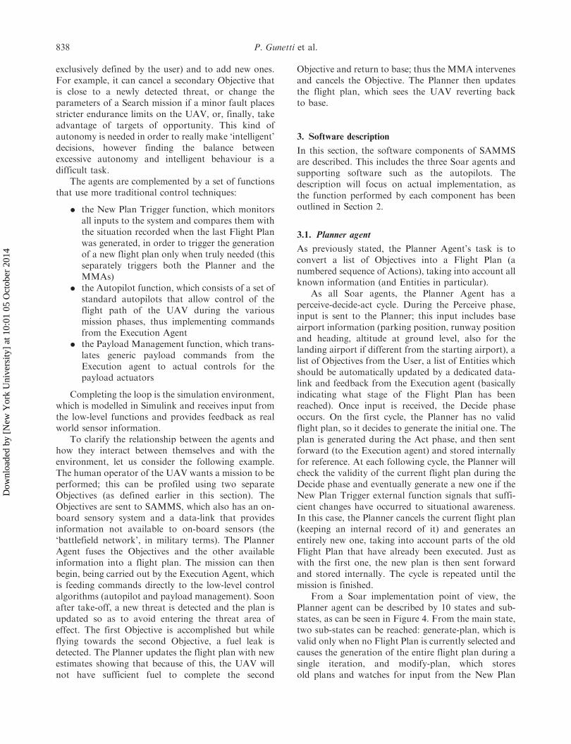
As all Soar agents, the Planner Agent has aperceive-decide-act cycle. During the Perceive phase,input is sent to the Planner; this input includes baseairport information (parking position, runway positionand heading, altitude at ground level, also for thelanding airport if different from the starting airport), alist of Objectives from the User, a list of Entities whichshould be automatically updated by a dedicated data-link and feedback from the Execution agent (basicallyindicating what stage of the Flight Plan has beenreached). Once input is received, the Decide phaseoccurs. On the first cycle, the Planner has no validflight plan, so it decides to generate the initial one. Theplan is generated during the Act phase, and then sentforward (to the Execution agent) and stored internallyfor reference. At each following cycle, the Planner willcheck the validity of the current flight plan during theDecide phase and eventually generate a new one if theNew Plan Trigger external function signals that suffi-cient changes have occurred to situational awareness.In this case, the Planner cancels the current flight plan(keeping an internal record of it) and generates anentirely new one, taking into account parts of the oldFlight Plan that have already been executed. Just aswith the first one, the new plan is then sent forwardand stored internally. The cycle is repeated until themission is finished.
From a Soar implementation point of view, thePlanner agent can be described by 10 states and sub-states, as can be seen in Figure 4. From the main state,two sub-states can be reached: generate-plan, which isvalid only when no Flight Plan is currently selected andcauses the generation of the entire flight plan during asingle iteration, and modify-plan, which storesold plans and watches for input from the New Plan
838 P. Gunetti et al.
Dow
nloa
ded
by [
New
Yor
k U
nive
rsity
] at
10:
01 0
5 O
ctob
er 2
014
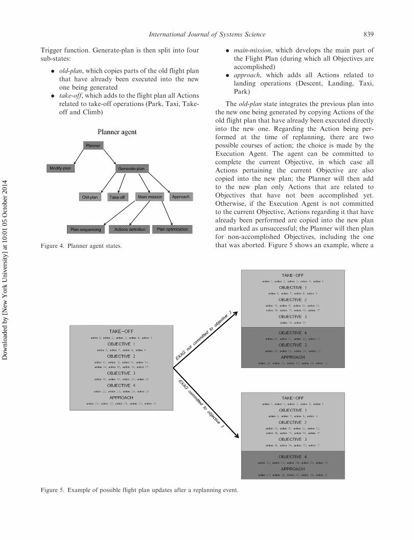
Trigger function. Generate-plan is then split into four
sub-states:
. old-plan, which copies parts of the old flight plan
that have already been executed into the new
one being generated. take-off, which adds to the flight plan all Actions
related to take-off operations (Park, Taxi, Take-
off and Climb)
. main-mission, which develops the main part of
the Flight Plan (during which all Objectives are
accomplished). approach, which adds all Actions related to
landing operations (Descent, Landing, Taxi,
Park)
The old-plan state integrates the previous plan into
the new one being generated by copying Actions of the
old flight plan that have already been executed directly
into the new one. Regarding the Action being per-
formed at the time of replanning, there are two
possible courses of action; the choice is made by the
Execution Agent. The agent can be committed to
complete the current Objective, in which case all
Actions pertaining the current Objective are also
copied into the new plan; the Planner will then add
to the new plan only Actions that are related to
Objectives that have not been accomplished yet.
Otherwise, if the Execution Agent is not committed
to the current Objective, Actions regarding it that have
already been performed are copied into the new plan
and marked as unsuccessful; the Planner will then plan
for non-accomplished Objectives, including the one
that was aborted. Figure 5 shows an example, where a
Figure 5. Example of possible flight plan updates after a replanning event.
Figure 4. Planner agent states.
International Journal of Systems Science 839
Dow
nloa
ded
by [
New
Yor
k U
nive
rsity
] at
10:
01 0
5 O
ctob
er 2
014
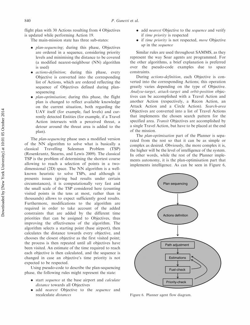
flight plan with 30 Actions resulting from 4 Objectivesis updated while performing Action 19.
The main-mission state has three sub-states:
. plan-sequencing; during this phase, Objectivesare ordered in a sequence, considering prioritylevels and minimising the distance to be covered(a modified nearest-neighbour (NN) algorithmis used)
. actions-definition; during this phase, everyObjective is converted into the correspondinglist of Actions, which are ordered reflecting thesequence of Objectives defined during plan-sequencing
. plan-optimisation; during this phase, the flightplan is changed to reflect available knowledgeon the current situation, both regarding theUAV itself (for example, fuel levels) and cur-rently detected Entities (for example, if a TravelAction intersects with a perceived threat, adetour around the threat area is added to theplan).
The plan-sequencing phase uses a modified versionof the NN algorithm to solve what is basically aclassical Travelling Salesman Problem (TSP)(Rosenkrantz, Stearns, and Lewis 2009). The classicalTSP is the problem of determining the shortest courseallowing to reach a selection of points in a two-dimensional (2D) space. The NN algorithm is a well-known heuristic to solve TSPs, and although itpresents issues (giving bad results under certaincircumstances), it is computationally very fast andthe small scale of the TSP considered here (countingvisited points in the tens at most, rather than inthousands) allows to expect sufficiently good results.Furthermore, modifications to the algorithm arerequired in order to take account of the addedconstraints that are added by the different timepriorities that can be assigned to Objectives, thusimproving the effectiveness of the algorithm. Thealgorithm selects a starting point (base airport), thencalculates the distance towards every objective, andchooses the closest objective as the first visited point;the process is then repeated until all objectives havebeen visited. An estimate of the time required to reacheach objective is then calculated, and the sequence ischanged in case an objective’s time priority is notexpected to be respected.
Using pseudo-code to describe the plan-sequencingphase, the following rules might represent the state:
. start sequence at the base airport and calculatedistance towards all Objectives
. add nearest Objective to the sequence andrecalculate distances
. add nearest Objective to the sequence and verifyif time priority is respected
. if time priority is not respected, move Objectiveup in the sequence
Similar rules are used throughout SAMMS, as theyrepresent the way Soar agents are programmed. Forthe other algorithms, a brief explanation is preferredover the pseudo-code examples due to spaceconstraints.
During actions-definition, each Objective is con-verted into the corresponding Actions; this operationgreatly varies depending on the type of Objective.Analyse-target, attack-target and orbit-position objec-tives can be accomplished with a Travel Action andanother Action (respectively, a Recon Action, anAttack Action and a Circle Action). Search-areaObjectives are converted into a list of Travel Actionsthat implements the chosen search pattern for thespecified area. Transit Objectives are accomplished bya single Travel Action, but have to be placed at the endof the mission.
The plan-optimisation part of the Planner is sepa-rated from the rest so that it can be as simple orcomplex as desired. Obviously, the more complex it is,the higher will be the level of intelligence of the system.In other words, while the rest of the Planner imple-ments autonomy, it is the plan-optimisation part thatimplements intelligence. As can be seen in Figure 6,
Figure 6. Planner agent flow diagram.
840 P. Gunetti et al.
Dow
nloa
ded
by [
New
Yor
k U
nive
rsity
] at
10:
01 0
5 O
ctob
er 2
014
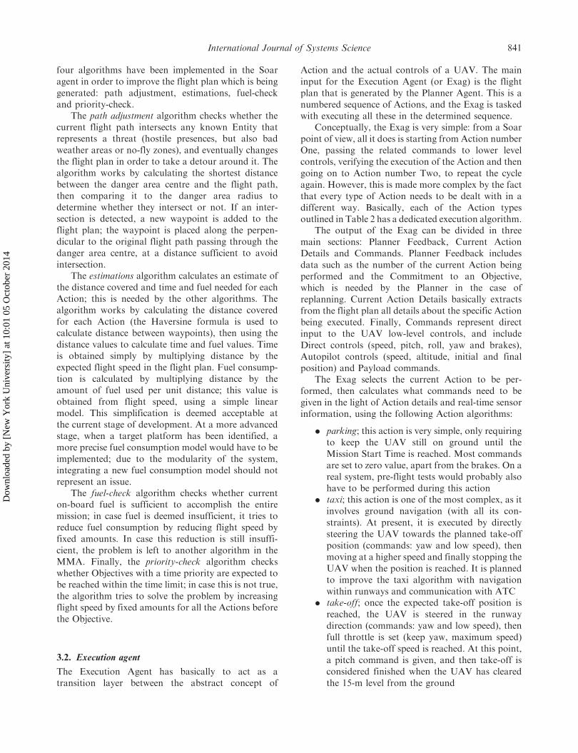
four algorithms have been implemented in the Soaragent in order to improve the flight plan which is beinggenerated: path adjustment, estimations, fuel-checkand priority-check.
The path adjustment algorithm checks whether thecurrent flight path intersects any known Entity thatrepresents a threat (hostile presences, but also badweather areas or no-fly zones), and eventually changesthe flight plan in order to take a detour around it. Thealgorithm works by calculating the shortest distancebetween the danger area centre and the flight path,then comparing it to the danger area radius todetermine whether they intersect or not. If an inter-section is detected, a new waypoint is added to theflight plan; the waypoint is placed along the perpen-dicular to the original flight path passing through thedanger area centre, at a distance sufficient to avoidintersection.
The estimations algorithm calculates an estimate ofthe distance covered and time and fuel needed for eachAction; this is needed by the other algorithms. Thealgorithm works by calculating the distance coveredfor each Action (the Haversine formula is used tocalculate distance between waypoints), then using thedistance values to calculate time and fuel values. Timeis obtained simply by multiplying distance by theexpected flight speed in the flight plan. Fuel consump-tion is calculated by multiplying distance by theamount of fuel used per unit distance; this value isobtained from flight speed, using a simple linearmodel. This simplification is deemed acceptable atthe current stage of development. At a more advancedstage, when a target platform has been identified, amore precise fuel consumption model would have to beimplemented; due to the modularity of the system,integrating a new fuel consumption model should notrepresent an issue.
The fuel-check algorithm checks whether currenton-board fuel is sufficient to accomplish the entiremission; in case fuel is deemed insufficient, it tries toreduce fuel consumption by reducing flight speed byfixed amounts. In case this reduction is still insuffi-cient, the problem is left to another algorithm in theMMA. Finally, the priority-check algorithm checkswhether Objectives with a time priority are expected tobe reached within the time limit; in case this is not true,the algorithm tries to solve the problem by increasingflight speed by fixed amounts for all the Actions beforethe Objective.
3.2. Execution agent
The Execution Agent has basically to act as atransition layer between the abstract concept of
Action and the actual controls of a UAV. The maininput for the Execution Agent (or Exag) is the flightplan that is generated by the Planner Agent. This is anumbered sequence of Actions, and the Exag is taskedwith executing all these in the determined sequence.
Conceptually, the Exag is very simple: from a Soarpoint of view, all it does is starting from Action numberOne, passing the related commands to lower levelcontrols, verifying the execution of the Action and thengoing on to Action number Two, to repeat the cycleagain. However, this is made more complex by the factthat every type of Action needs to be dealt with in adifferent way. Basically, each of the Action typesoutlined in Table 2 has a dedicated execution algorithm.
The output of the Exag can be divided in threemain sections: Planner Feedback, Current ActionDetails and Commands. Planner Feedback includesdata such as the number of the current Action beingperformed and the Commitment to an Objective,which is needed by the Planner in the case ofreplanning. Current Action Details basically extractsfrom the flight plan all details about the specific Actionbeing executed. Finally, Commands represent directinput to the UAV low-level controls, and includeDirect controls (speed, pitch, roll, yaw and brakes),Autopilot controls (speed, altitude, initial and finalposition) and Payload commands.
The Exag selects the current Action to be per-formed, then calculates what commands need to begiven in the light of Action details and real-time sensorinformation, using the following Action algorithms:
. parking; this action is very simple, only requiringto keep the UAV still on ground until theMission Start Time is reached. Most commandsare set to zero value, apart from the brakes. On areal system, pre-flight tests would probably alsohave to be performed during this action
. taxi; this action is one of the most complex, as itinvolves ground navigation (with all its con-straints). At present, it is executed by directlysteering the UAV towards the planned take-offposition (commands: yaw and low speed), thenmoving at a higher speed and finally stopping theUAV when the position is reached. It is plannedto improve the taxi algorithm with navigationwithin runways and communication with ATC
. take-off; once the expected take-off position isreached, the UAV is steered in the runwaydirection (commands: yaw and low speed), thenfull throttle is set (keep yaw, maximum speed)until the take-off speed is reached. At this point,a pitch command is given, and then take-off isconsidered finished when the UAV has clearedthe 15-m level from the ground
International Journal of Systems Science 841
Dow
nloa
ded
by [
New
Yor
k U
nive
rsity
] at
10:
01 0
5 O
ctob
er 2
014

. climb; immediately after take-off, the Climbaction keeps the UAV in the take-off direction(and then in the direction of the first Objective)and sets a fixed climb rate that allows it to reacha desired altitude. When this altitude is reached,a level flight condition is entered and then themain mission begins to be executed
. main-mission-start; this is not a proper action,but still needs to be dealt with by the Exag, sinceit is a defining part of a flight plan
. travel; this is the most important type of action,and the first type to make full use of theAutopilot functions. It basically sets a great-circle route (shortest distance between two pointson a sphere) between the current position and theintended destination, at the specified speed andaltitude. The distance to the destination positionis continuously verified in order to make deci-sions regarding the Commitment to the Objective
. target-recon; this action involves a pass over atarget in order to allow a sensor payload togather data. Once the target position is reached,a turn-around approach waypoint is set; theUAV then travels towards it before steeringback towards the target for the actual datagathering pass. Usually, during a pass, thedesired altitude is different from cruise altitude,so this is also changed
. target-attack; this action is very similar to target-recon, but can use different parameters indetermining the type of approach and ofcourse uses a different type of payload
. circle-hover; in this action, four waypointsforming a diamond are calculated around thecentral position. The UAV then cycles throughthose in clock-wise (or anti-clockwise) direction,until the specified time limit is reached
. main-mission-end; as with main-mission-start
. descent; in this Action, after the expected land-ing position has been reached in flight, twowaypoints are calculated and reached using theautopilot. These waypoints basically draw anideal descent path that is in line with the runway
. landing; this Action makes use of the Directcontrols rather than the Autopilot, and has theUAV descend at a specific angle, then perform aflare manoeuvre when close to the ground andfinally stop when ground contact has beenensured.
3.3. Mission manager agent
The MMA acts at the highest level within SAMMS.Most planning algorithms are placed within the
Planner Agent, but the Planner does not have the
authority to change Objectives: this means that the
Planner on its own cannot exclude an Objective, nor
can it add new ones (this might be desirable for certain
types of mission). The MMA deals with all tasks that
require direct intervention on the list of Objectives.Input for the MMA is represented by a large
amount of information: the list of current User
Objectives, the Entity information, airframe informa-
tion and the current flight plan generated by the
Planner (together with the estimates obtained by the
estimations algorithm). The agent works by identifying
inconsistencies (there are several types, described later)
and then using dedicated algorithms to solve them by
deriving a new list of Objectives, which may include
several changes depending on the current situation.The agent works similarly to the Planner Agent, as
it is triggered by an external function and is waiting for
changes during most of the time. When the trigger
function detects that a new check of the current
situation is needed, the MMA goes through a list of
algorithms that determine and apply necessary changes
to the Objectives. There are basically three types of
actions that the MMA can do: modify an Objective,
remove an Objective or add a new Objective.There are five types of inconsistencies that can
determine a change to an Objective or its removal: a
priority problem, a target position problem, a fuel
problem, a threat problem or a payload problem. A
priority problem occurs when an Objective has a time
priority but the estimations for the generated flight
plan imply that the time priority will not be respected
(the Objective cannot be executed before the specified
time). This means that both the plan-sequencing algo-
rithm and the plan-optimisation algorithm have failed
in generating a plan that respects the priority; thus, at
this stage, the MMA actually decides to ignore the
priority and thus advises the User of this decision
(usually, this type of problem will be caused by anincorrectly set or unrealistic time priority).
A target position problem occurs when the target
for an Analyse or Attack Objective is moving. In such
cases, position information entered by the User needs
to be updated using the corresponding Entity
information.A fuel problem occurs when current on-board fuel
is deemed insufficient to complete the mission, even
after the Planner has tried to reduce fuel consumption
by decreasing flight speed. In this case, two possible
courses of actions can be taken: if a Search Objective is
present, the resolution of the search can be increased,
so that the distance to be covered is reduced; otherwise,
the algorithm chooses an Objective to be cancelled (the
decision is based on two factors: execution priority of
842 P. Gunetti et al.
Dow
nloa
ded
by [
New
Yor
k U
nive
rsity
] at
10:
01 0
5 O
ctob
er 2
014
Objectives, and relative distance between the missionstarting point and the Objectives).
A threat problem occurs when an Objective isplaced within the danger area of an Entity. In this case,the algorithm will decide to remove the Objective if itsexecution priority is lower than the threat level of theEntity.
A payload problem occurs when airframe statusdata indicates that the payload related to a certain typeof mission has failed. In this case, Objectives of thattype are removed, since the mission cannot be accom-plished anyway.
The other type of action that the MMA canperform is the addition of a new Objective. This isusually related to Search Objectives specified by theUser. Search Objectives can be specified as puresearches, search-and-analyse or search-and-attack mis-sions, the latter meaning that should a new Entity bedetected within the Search area, the related actionshould be performed on it (either analyse or attack).Thus, the MMA looks at the current Entity status andif a new Entity is detected within the search area, itadds a new Objective, of the Analyse or Attack type, tothe list given by the User.
It is important to understand that giving theauthority to autonomously change, add or removeObjectives to the system can severely impact itsdeterminism. This is the main reason why this func-tionality is implemented in an agent which is separatefrom the Planner: while the functionality provided byMMA is important in making SAMMS an intelligentsystem, it is possible to completely disregard it ifdeterminism is deemed to be a higher concern, withoutlosing the functionality provided by the Planner. Sinceone of the perceived advantages of the Soar-basedapproach to Mission Management is the possibility tovalidate and certify such a system, maintaining deter-minism is very important within the scope of theproject.
In fact, the algorithms implemented within theMMA are fully deterministic, thus any change tocurrent Objectives is exclusively a consequence of achange in situational awareness. The lack of determin-ism arises from the lack of knowledge regarding themission; when new knowledge is gained in-flight, thismay result in an unexpected change from the originalflight plan (a change that the system will make in orderto improve the possibility to successfully complete themission). The ability to respond to a dynamic envi-ronment is one of the driving ideas behind the entiresystem; however, this inevitably comes at the cost ofdeterminism. Separate implementation of the algo-rithms with the authority to change mission objectivesallows SAMMS to be more flexibly configured for theactual UAV on which it is used, depending on the
specific needs (for example, a transport mission in anon-hostile environment would likely not require theMMA to be active).
3.4. Supporting software
Supporting software components are the New PlanTrigger, the Autopilot and the Payload Managementsoftware. Payload Management is heavily dependenton the actual platform and mission, so since this is ageneric architecture, it has not been implemented.
The New Plan Trigger function triggers both thePlanner Agent and the MMA. The agents are sepa-rately triggered when the relative conditions are met.For the Planner Agent, the conditions that can triggera new plan are: airport data change, Objectives change,change of certain Entity properties and certain air-frame data values. For the MMA, these conditions are:Objectives change (including new ones that are intro-duced by the User as the mission is executed), Entitieschange, airframe data change and the availability of anew plan from the Planner.
The Autopilot function is heavily dependent on theactual platform; however, an example autopilot hasbeen implemented, specifically designed for theintended simulation test model (see Section 4 fordetails). The autopilot uses several proportional-integral-derivative controller loops to achieve its func-tions. The controller loops are: pitch-hold, speed-hold,roll-hold, yaw-hold, altitude-hold and bearing calcula-tion; yaw-damper functionality is also implemented.The roll-hold loop keeps the UAV at a specified rollangle by commanding the aileron deflection; inSAMMS, it is never used directly, but only as aninner loop for the yaw-hold loop. The yaw-hold loopsteers the UAV towards the specified bearing, and itdoes so by commanding a roll angle to the roll-holdloop. The bearing calculation loop calculates thebearing necessary to reach a desired destination,which is then fed to the yaw-hold loop. The speed-hold loop commands the throttle so that a desiredspeed can be maintained. The pitch-hold loop keepsthe UAV at a specified pitch angle by commanding theelevators. The altitude-hold loop allows to specify aflight altitude for the UAV, which is then kept byfeeding pitch angle commands to the pitch-hold loop.Finally, the yaw-damper algorithm commands therudder so that turns are coordinated and sideslip isavoided.
The Autopilot has two main operating modes;during Direct control, the Execution Agent providescommands in the form of desired pitch, yaw and speed,thus only the first four loops (roll-hold, yaw-hold,pitch-hold and speed-hold) are used. Instead, in full
International Journal of Systems Science 843
Dow
nloa
ded
by [
New
Yor
k U
nive
rsity
] at
10:
01 0
5 O
ctob
er 2
014
Autopilot mode, the Execution Agent provides com-mands as desired destination, altitude and speed, thusall the loops are used, with the altitude-hold loopfunctioning as the outer loop for the pitch-hold loopand the bearing calculation loop functioning as theouter loop for the yaw-hold loop. The yaw-damperloop is always active.
4. Simulation
In order to verify the functionality of SAMMS, adedicated simulation environment has been set up.During these simulations, realistic input is fed toSAMMS, and the output is fed to a model of UAVdynamics; thus, verifying the capability of SAMMS toguide the UAV through an entire mission. Thesimulation environment is based on a Simulinkmodel of the Pioneer UAV. This was chosen as it isrepresentative of the type of UAV towards whichSAMMS is tailored (small, slow-flying and low-cost).
The model is based on the generic aircraft modelthat was released by Campa in 2004, although severalmodifications were implemented in order to allow thesimulation of ground operations (taxi, take-off andlanding). This model uses non-linear equations ofmotion, however, aerodynamic forces are calculatedusing a linear model and the calculation of thrust issimplified; thus, the model does not provide highfidelity, but this has been deemed acceptable, since thepurpose of the simulation is not to validate the low-level control algorithms, but to test the missionmanagement algorithms, that operate on a differenttimescale and do not require tailoring for the specificaircraft being used. In general, the autonomous mis-sion management functionality is independent from theunderlying platform and low-level algorithms.Knowledge about the aircraft capabilities is passed toSAMMS through a set of dedicated parameters thatare used throughout the system and completely definethe aircraft from a mission management point of view.Low-level control (the autopilots) is tuned to theparticular UAV model being used in the simulations,but tuning it to any other aircraft model should notrepresent an issue, especially since the autopilot loopsused are standard.
The purpose of the simulations is two-fold: pri-marily, to prove that the flight plans generated bySAMMS in various situations are correct, and second-arily to verify that the system respects real-timerequirements and is capable to control the aircraftduring all flight phases. Thus, two sets of data arelogged: the flight plan which is the main output of thePlanner Agent, and the flight data generated by themodel. From these, a set of graphs is derived, allowing
the description of the flight plan and the validation ofthe entire system with all functions.
Since the amount of variables that constitute inputfor the system is very large, verification of all possibleinput configurations is virtually impossible. For thisreason, a set of six scenarios has been prepared. Inputscenarios are constituted by base airport information,the list of current Objectives and the list of currentEntities. The scenarios are intended to be representa-tive of the possible conditions that SAMMS mightencounter; for each scenario, several scenario varia-tions have been devised, in order to allow testing ofparticular algorithms. While all scenario variationshave been tested during our simulations, only three ofthem (indicated as scenario 1, 2 and 3 in the article) willbe analysed in the following sections, due to spaceconstraints. The choice of visualised scenarios is meantto provide proof of the capabilities demonstrated bythe SAMMS architecture; for each presented scenariovariation, a textual description of the scenario, a plotof the resulting flight plan and a plot of the simulatedtrajectory of the UAV are presented.
4.1. Scenario 1
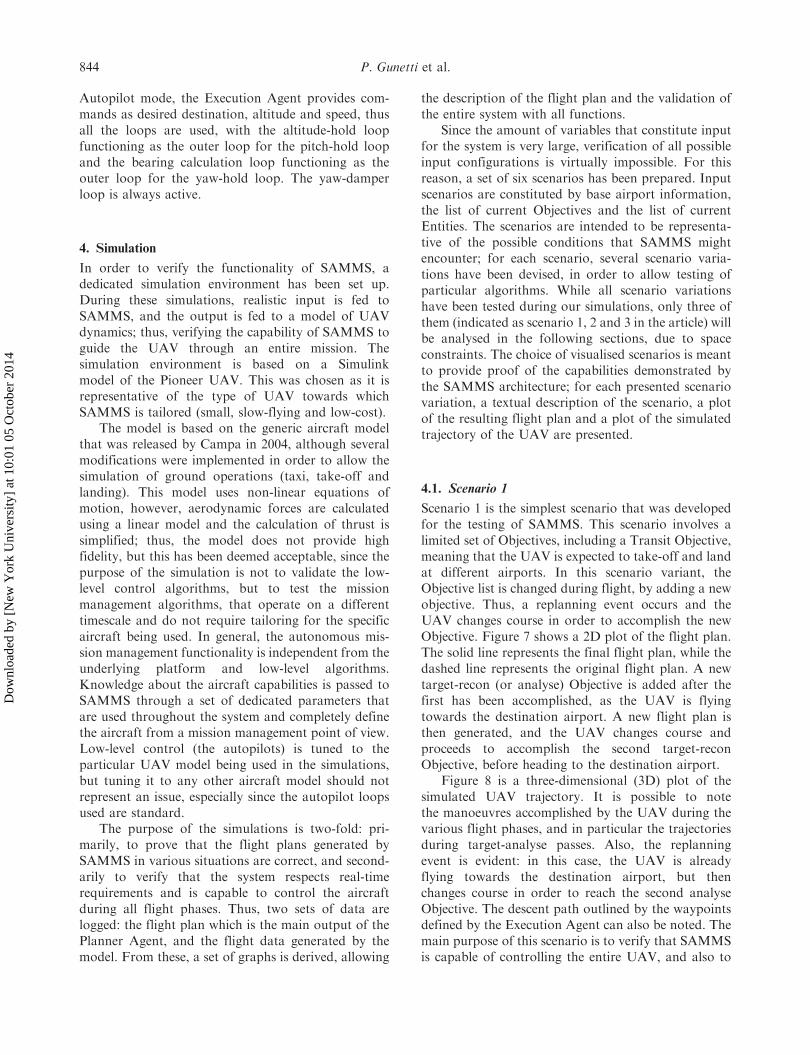
Scenario 1 is the simplest scenario that was developedfor the testing of SAMMS. This scenario involves alimited set of Objectives, including a Transit Objective,meaning that the UAV is expected to take-off and landat different airports. In this scenario variant, theObjective list is changed during flight, by adding a newobjective. Thus, a replanning event occurs and theUAV changes course in order to accomplish the newObjective. Figure 7 shows a 2D plot of the flight plan.The solid line represents the final flight plan, while thedashed line represents the original flight plan. A newtarget-recon (or analyse) Objective is added after thefirst has been accomplished, as the UAV is flyingtowards the destination airport. A new flight plan isthen generated, and the UAV changes course andproceeds to accomplish the second target-reconObjective, before heading to the destination airport.
Figure 8 is a three-dimensional (3D) plot of thesimulated UAV trajectory. It is possible to notethe manoeuvres accomplished by the UAV during thevarious flight phases, and in particular the trajectoriesduring target-analyse passes. Also, the replanningevent is evident: in this case, the UAV is alreadyflying towards the destination airport, but thenchanges course in order to reach the second analyseObjective. The descent path outlined by the waypointsdefined by the Execution Agent can also be noted. Themain purpose of this scenario is to verify that SAMMSis capable of controlling the entire UAV, and also to
844 P. Gunetti et al.
Dow
nloa
ded
by [
New
Yor
k U
nive
rsity
] at
10:
01 0
5 O
ctob
er 2
014
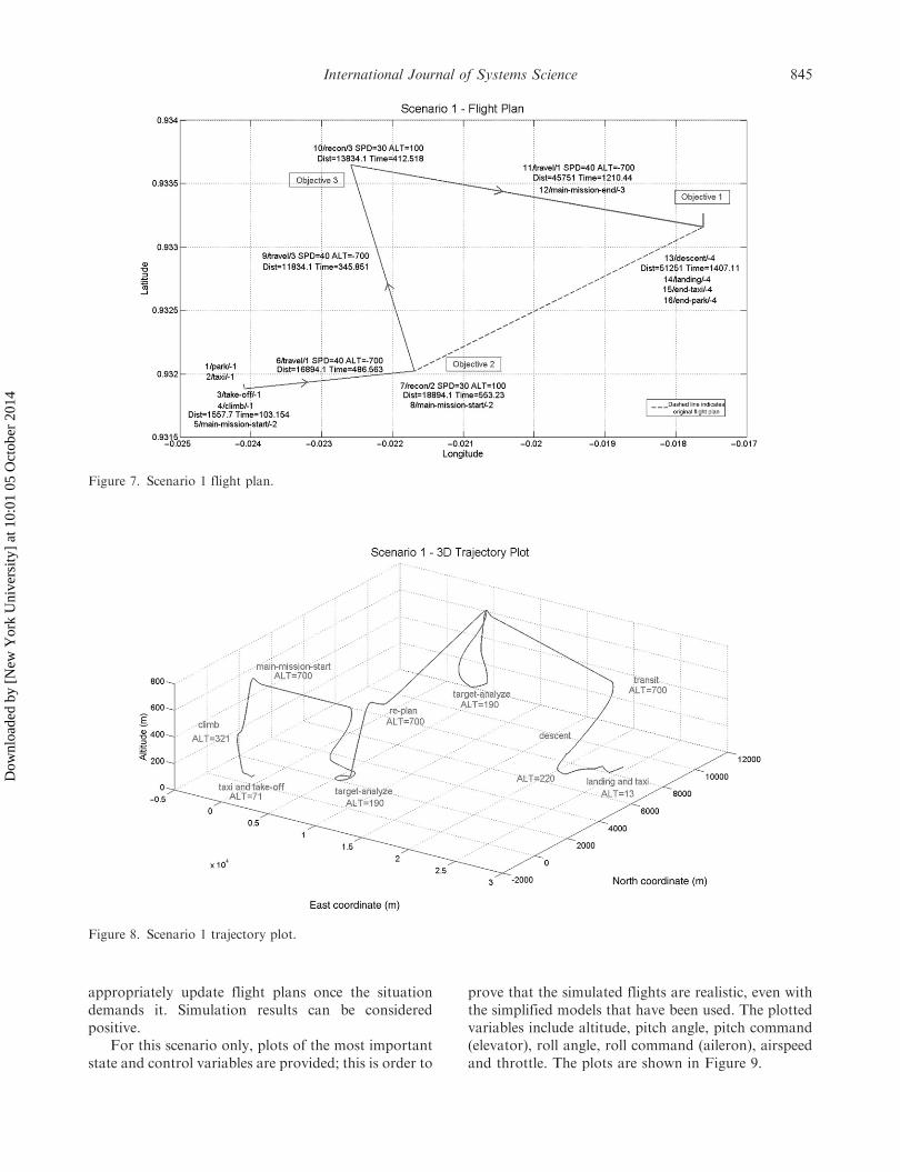
appropriately update flight plans once the situationdemands it. Simulation results can be consideredpositive.
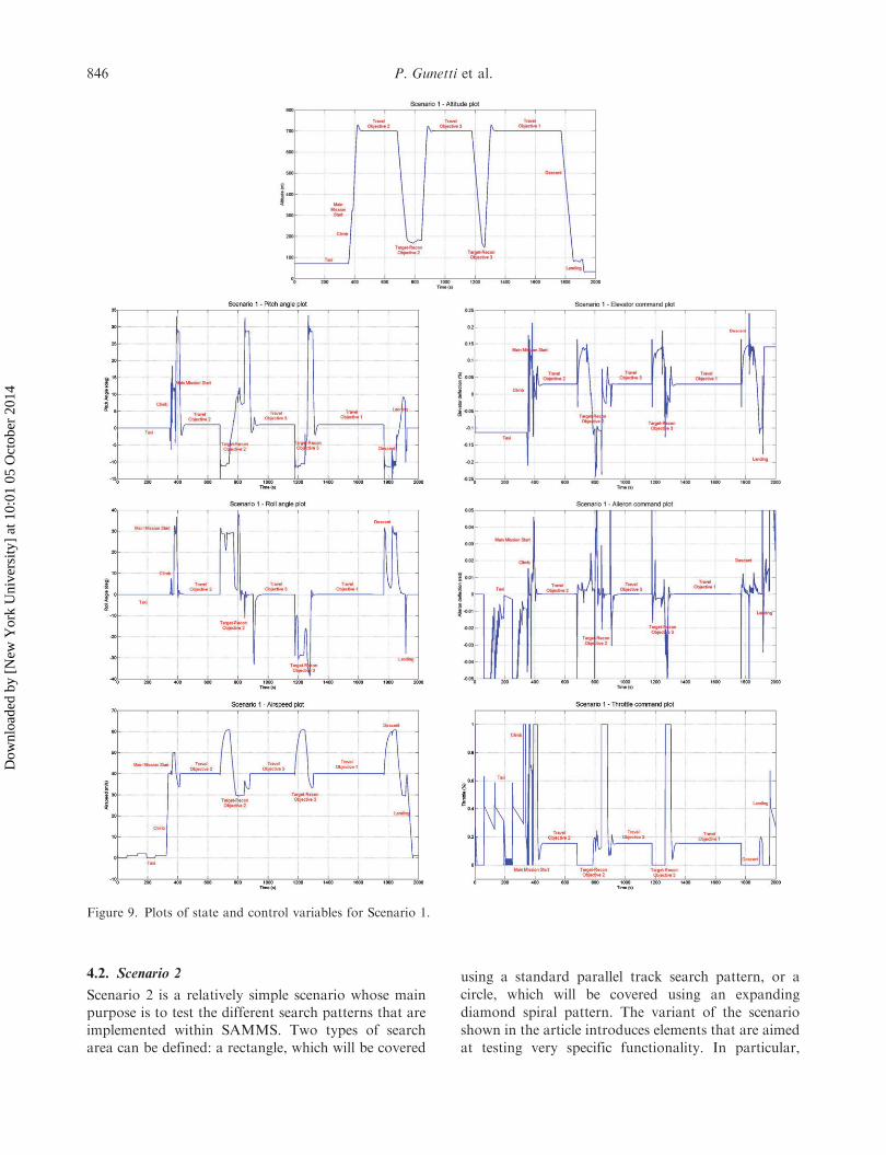
For this scenario only, plots of the most importantstate and control variables are provided; this is order to
prove that the simulated flights are realistic, even withthe simplified models that have been used. The plottedvariables include altitude, pitch angle, pitch command(elevator), roll angle, roll command (aileron), airspeedand throttle. The plots are shown in Figure 9.
Figure 8. Scenario 1 trajectory plot.
Figure 7. Scenario 1 flight plan.
International Journal of Systems Science 845
Dow
nloa
ded
by [
New
Yor
k U
nive
rsity
] at
10:
01 0
5 O
ctob
er 2
014
4.2. Scenario 2
Scenario 2 is a relatively simple scenario whose mainpurpose is to test the different search patterns that areimplemented within SAMMS. Two types of searcharea can be defined: a rectangle, which will be covered
using a standard parallel track search pattern, or a
circle, which will be covered using an expanding
diamond spiral pattern. The variant of the scenario
shown in the article introduces elements that are aimed
at testing very specific functionality. In particular,
Figure 9. Plots of state and control variables for Scenario 1.
846 P. Gunetti et al.
Dow
nloa
ded
by [
New
Yor
k U
nive
rsity
] at
10:
01 0
5 O
ctob
er 2
014
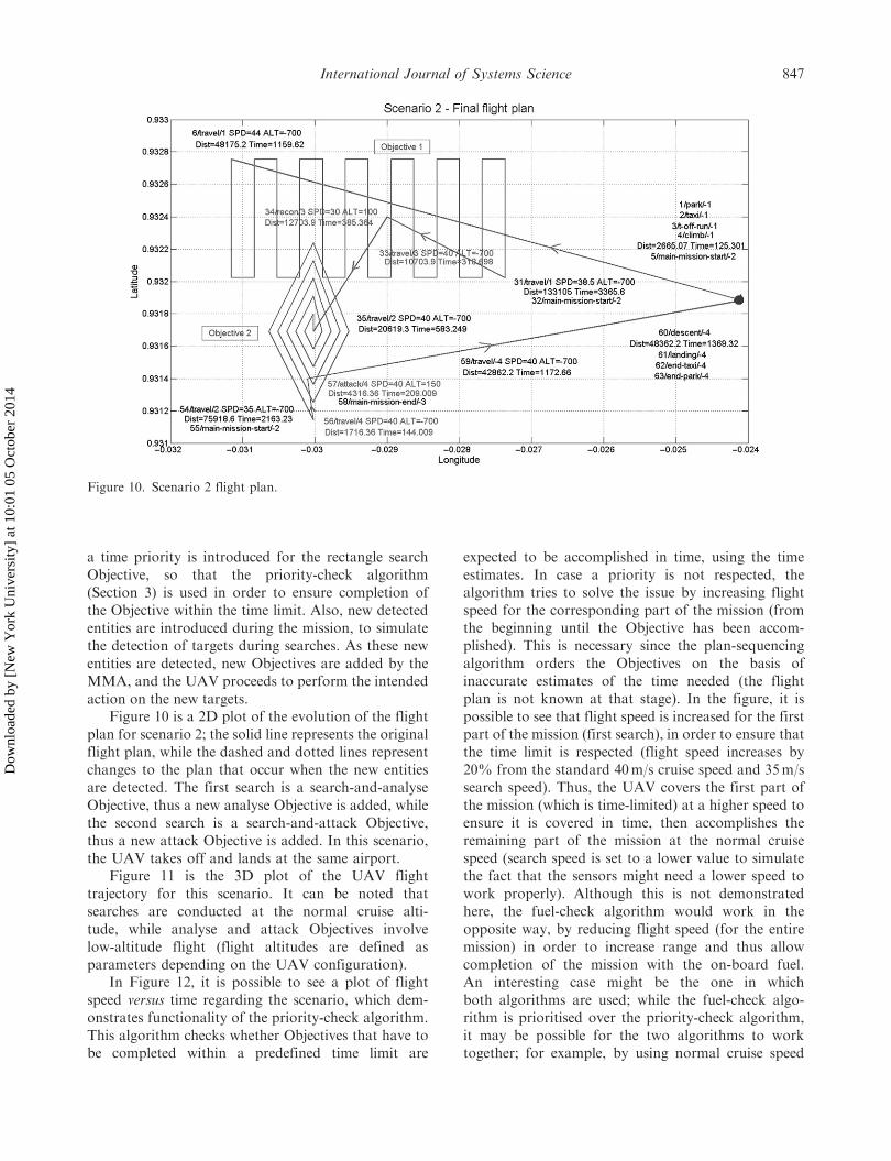
a time priority is introduced for the rectangle searchObjective, so that the priority-check algorithm(Section 3) is used in order to ensure completion ofthe Objective within the time limit. Also, new detectedentities are introduced during the mission, to simulatethe detection of targets during searches. As these newentities are detected, new Objectives are added by theMMA, and the UAV proceeds to perform the intendedaction on the new targets.
Figure 10 is a 2D plot of the evolution of the flightplan for scenario 2; the solid line represents the originalflight plan, while the dashed and dotted lines representchanges to the plan that occur when the new entitiesare detected. The first search is a search-and-analyseObjective, thus a new analyse Objective is added, whilethe second search is a search-and-attack Objective,thus a new attack Objective is added. In this scenario,the UAV takes off and lands at the same airport.
Figure 11 is the 3D plot of the UAV flighttrajectory for this scenario. It can be noted thatsearches are conducted at the normal cruise alti-tude, while analyse and attack Objectives involvelow-altitude flight (flight altitudes are defined asparameters depending on the UAV configuration).
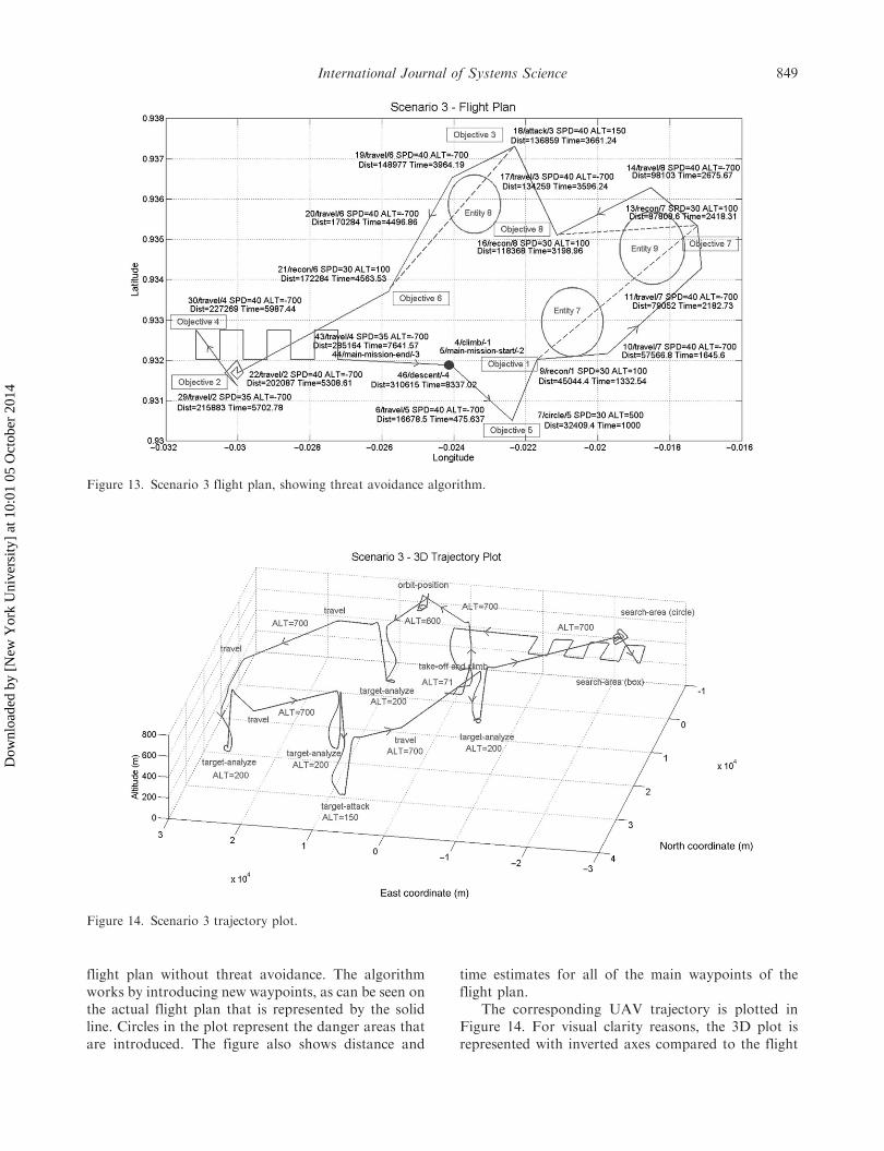
In Figure 12, it is possible to see a plot of flightspeed versus time regarding the scenario, which dem-onstrates functionality of the priority-check algorithm.This algorithm checks whether Objectives that have tobe completed within a predefined time limit are
expected to be accomplished in time, using the timeestimates. In case a priority is not respected, thealgorithm tries to solve the issue by increasing flightspeed for the corresponding part of the mission (fromthe beginning until the Objective has been accom-plished). This is necessary since the plan-sequencingalgorithm orders the Objectives on the basis ofinaccurate estimates of the time needed (the flightplan is not known at that stage). In the figure, it ispossible to see that flight speed is increased for the firstpart of the mission (first search), in order to ensure thatthe time limit is respected (flight speed increases by20% from the standard 40m/s cruise speed and 35m/ssearch speed). Thus, the UAV covers the first part ofthe mission (which is time-limited) at a higher speed toensure it is covered in time, then accomplishes theremaining part of the mission at the normal cruisespeed (search speed is set to a lower value to simulatethe fact that the sensors might need a lower speed towork properly). Although this is not demonstratedhere, the fuel-check algorithm would work in theopposite way, by reducing flight speed (for the entiremission) in order to increase range and thus allowcompletion of the mission with the on-board fuel.An interesting case might be the one in whichboth algorithms are used; while the fuel-check algo-rithm is prioritised over the priority-check algorithm,it may be possible for the two algorithms to worktogether; for example, by using normal cruise speed
Figure 10. Scenario 2 flight plan.
International Journal of Systems Science 847
Dow
nloa
ded
by [
New
Yor
k U
nive
rsity
] at
10:
01 0
5 O
ctob
er 2
014
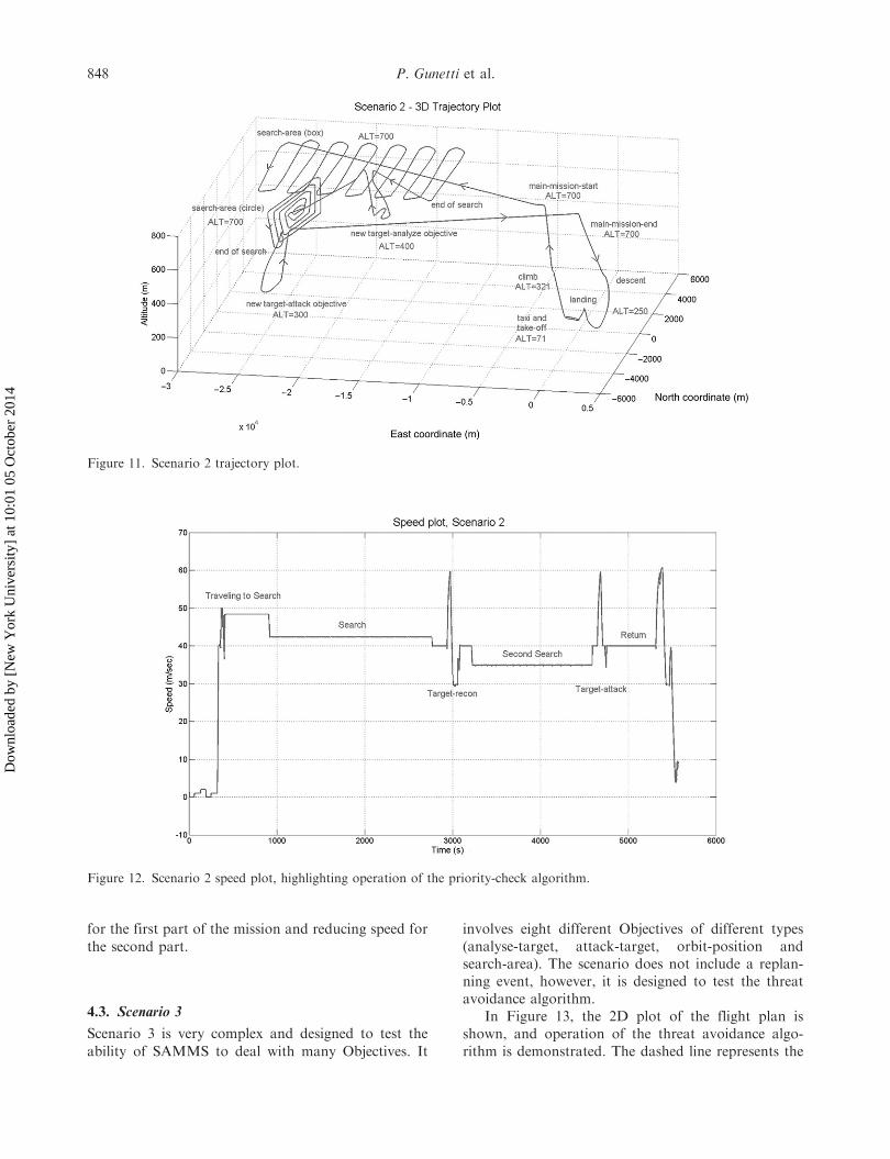
for the first part of the mission and reducing speed forthe second part.
4.3. Scenario 3
Scenario 3 is very complex and designed to test the
ability of SAMMS to deal with many Objectives. It
involves eight different Objectives of different types(analyse-target, attack-target, orbit-position andsearch-area). The scenario does not include a replan-ning event, however, it is designed to test the threatavoidance algorithm.
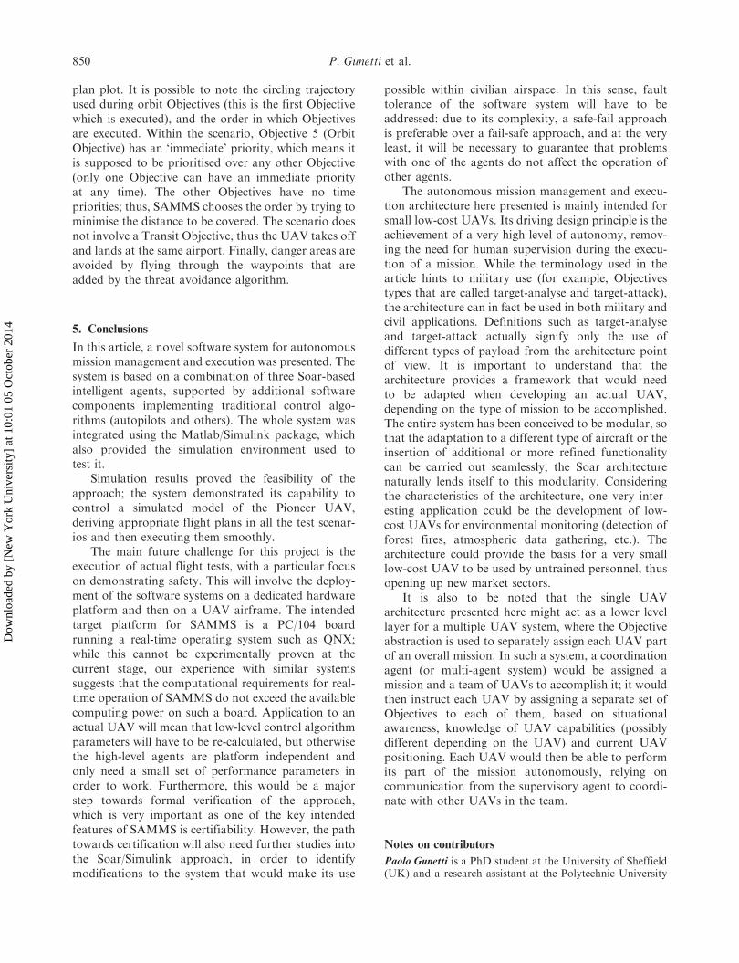
In Figure 13, the 2D plot of the flight plan isshown, and operation of the threat avoidance algo-rithm is demonstrated. The dashed line represents the
Figure 12. Scenario 2 speed plot, highlighting operation of the priority-check algorithm.
Figure 11. Scenario 2 trajectory plot.
848 P. Gunetti et al.
Dow
nloa
ded
by [
New
Yor
k U
nive
rsity
] at
10:
01 0
5 O
ctob
er 2
014
flight plan without threat avoidance. The algorithmworks by introducing new waypoints, as can be seen onthe actual flight plan that is represented by the solidline. Circles in the plot represent the danger areas thatare introduced. The figure also shows distance and
time estimates for all of the main waypoints of theflight plan.
The corresponding UAV trajectory is plotted inFigure 14. For visual clarity reasons, the 3D plot isrepresented with inverted axes compared to the flight
Figure 13. Scenario 3 flight plan, showing threat avoidance algorithm.
Figure 14. Scenario 3 trajectory plot.
International Journal of Systems Science 849
Dow
nloa
ded
by [
New
Yor
k U
nive
rsity
] at
10:
01 0
5 O
ctob
er 2
014
plan plot. It is possible to note the circling trajectoryused during orbit Objectives (this is the first Objectivewhich is executed), and the order in which Objectivesare executed. Within the scenario, Objective 5 (OrbitObjective) has an ‘immediate’ priority, which means itis supposed to be prioritised over any other Objective(only one Objective can have an immediate priorityat any time). The other Objectives have no timepriorities; thus, SAMMS chooses the order by trying tominimise the distance to be covered. The scenario doesnot involve a Transit Objective, thus the UAV takes offand lands at the same airport. Finally, danger areas areavoided by flying through the waypoints that areadded by the threat avoidance algorithm.
5. Conclusions
In this article, a novel software system for autonomousmission management and execution was presented. Thesystem is based on a combination of three Soar-basedintelligent agents, supported by additional softwarecomponents implementing traditional control algo-rithms (autopilots and others). The whole system wasintegrated using the Matlab/Simulink package, whichalso provided the simulation environment used totest it.
Simulation results proved the feasibility of theapproach; the system demonstrated its capability tocontrol a simulated model of the Pioneer UAV,deriving appropriate flight plans in all the test scenar-ios and then executing them smoothly.
The main future challenge for this project is theexecution of actual flight tests, with a particular focuson demonstrating safety. This will involve the deploy-ment of the software systems on a dedicated hardwareplatform and then on a UAV airframe. The intendedtarget platform for SAMMS is a PC/104 boardrunning a real-time operating system such as QNX;while this cannot be experimentally proven at thecurrent stage, our experience with similar systemssuggests that the computational requirements for real-time operation of SAMMS do not exceed the availablecomputing power on such a board. Application to anactual UAV will mean that low-level control algorithmparameters will have to be re-calculated, but otherwisethe high-level agents are platform independent andonly need a small set of performance parameters inorder to work. Furthermore, this would be a majorstep towards formal verification of the approach,which is very important as one of the key intendedfeatures of SAMMS is certifiability. However, the pathtowards certification will also need further studies intothe Soar/Simulink approach, in order to identifymodifications to the system that would make its use
possible within civilian airspace. In this sense, faulttolerance of the software system will have to beaddressed: due to its complexity, a safe-fail approachis preferable over a fail-safe approach, and at the veryleast, it will be necessary to guarantee that problemswith one of the agents do not affect the operation ofother agents.
The autonomous mission management and execu-tion architecture here presented is mainly intended forsmall low-cost UAVs. Its driving design principle is theachievement of a very high level of autonomy, remov-ing the need for human supervision during the execu-tion of a mission. While the terminology used in thearticle hints to military use (for example, Objectivestypes that are called target-analyse and target-attack),the architecture can in fact be used in both military andcivil applications. Definitions such as target-analyseand target-attack actually signify only the use ofdifferent types of payload from the architecture pointof view. It is important to understand that thearchitecture provides a framework that would needto be adapted when developing an actual UAV,depending on the type of mission to be accomplished.The entire system has been conceived to be modular, sothat the adaptation to a different type of aircraft or theinsertion of additional or more refined functionalitycan be carried out seamlessly; the Soar architecturenaturally lends itself to this modularity. Consideringthe characteristics of the architecture, one very inter-esting application could be the development of low-cost UAVs for environmental monitoring (detection offorest fires, atmospheric data gathering, etc.). Thearchitecture could provide the basis for a very smalllow-cost UAV to be used by untrained personnel, thusopening up new market sectors.
It is also to be noted that the single UAVarchitecture presented here might act as a lower levellayer for a multiple UAV system, where the Objectiveabstraction is used to separately assign each UAV partof an overall mission. In such a system, a coordinationagent (or multi-agent system) would be assigned amission and a team of UAVs to accomplish it; it wouldthen instruct each UAV by assigning a separate set ofObjectives to each of them, based on situationalawareness, knowledge of UAV capabilities (possiblydifferent depending on the UAV) and current UAVpositioning. Each UAV would then be able to performits part of the mission autonomously, relying oncommunication from the supervisory agent to coordi-nate with other UAVs in the team.
Notes on contributors
Paolo Gunetti is a PhD student at the University of Sheffield(UK) and a research assistant at the Polytechnic University
850 P. Gunetti et al.
Dow
nloa
ded
by [
New
Yor
k U
nive
rsity
] at
10:
01 0
5 O
ctob
er 2
014
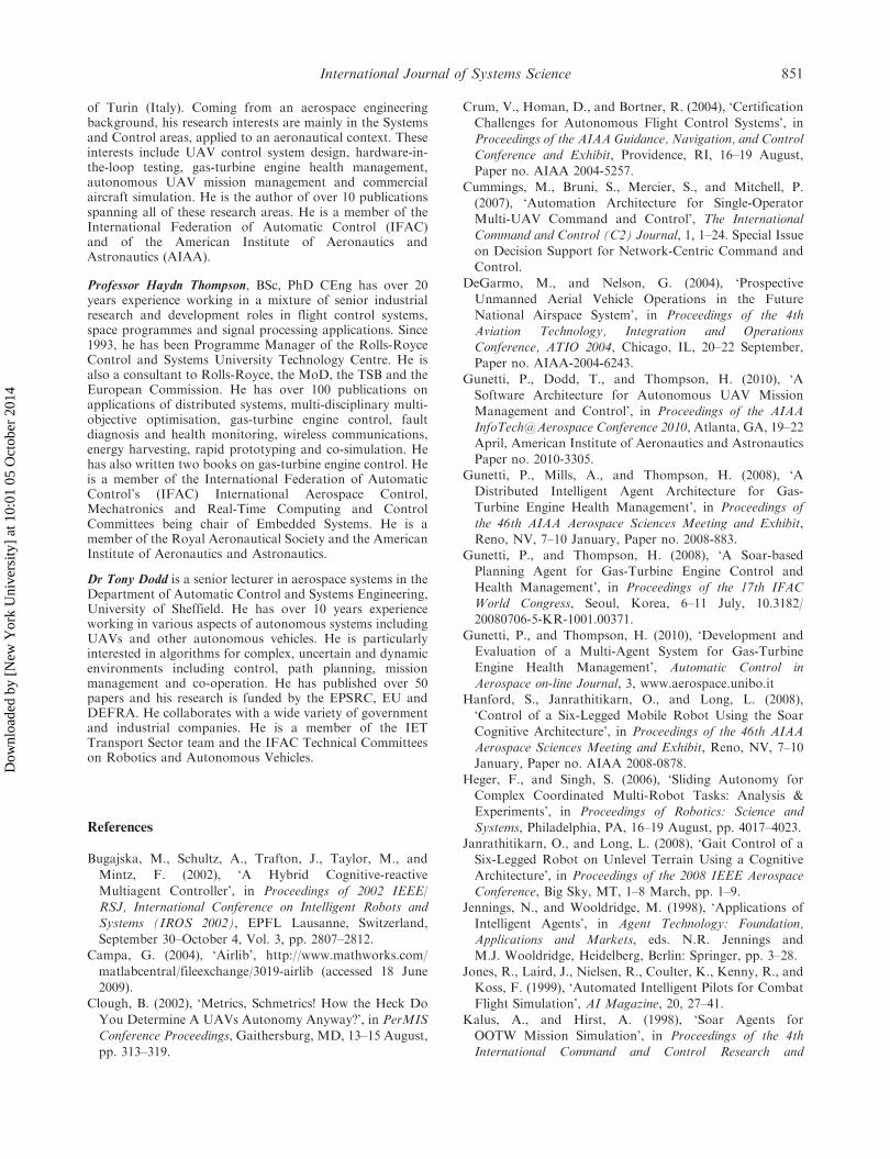
of Turin (Italy). Coming from an aerospace engineeringbackground, his research interests are mainly in the Systemsand Control areas, applied to an aeronautical context. Theseinterests include UAV control system design, hardware-in-the-loop testing, gas-turbine engine health management,autonomous UAV mission management and commercialaircraft simulation. He is the author of over 10 publicationsspanning all of these research areas. He is a member of theInternational Federation of Automatic Control (IFAC)and of the American Institute of Aeronautics andAstronautics (AIAA).
Professor Haydn Thompson, BSc, PhD CEng has over 20years experience working in a mixture of senior industrialresearch and development roles in flight control systems,space programmes and signal processing applications. Since1993, he has been Programme Manager of the Rolls-RoyceControl and Systems University Technology Centre. He isalso a consultant to Rolls-Royce, the MoD, the TSB and theEuropean Commission. He has over 100 publications onapplications of distributed systems, multi-disciplinary multi-objective optimisation, gas-turbine engine control, faultdiagnosis and health monitoring, wireless communications,energy harvesting, rapid prototyping and co-simulation. Hehas also written two books on gas-turbine engine control. Heis a member of the International Federation of AutomaticControl’s (IFAC) International Aerospace Control,Mechatronics and Real-Time Computing and ControlCommittees being chair of Embedded Systems. He is amember of the Royal Aeronautical Society and the AmericanInstitute of Aeronautics and Astronautics.
Dr Tony Dodd is a senior lecturer in aerospace systems in theDepartment of Automatic Control and Systems Engineering,University of Sheffield. He has over 10 years experienceworking in various aspects of autonomous systems includingUAVs and other autonomous vehicles. He is particularlyinterested in algorithms for complex, uncertain and dynamicenvironments including control, path planning, missionmanagement and co-operation. He has published over 50papers and his research is funded by the EPSRC, EU andDEFRA. He collaborates with a wide variety of governmentand industrial companies. He is a member of the IETTransport Sector team and the IFAC Technical Committeeson Robotics and Autonomous Vehicles.
References
Bugajska, M., Schultz, A., Trafton, J., Taylor, M., and
Mintz, F. (2002), ‘A Hybrid Cognitive-reactive
Multiagent Controller’, in Proceedings of 2002 IEEE/
RSJ, International Conference on Intelligent Robots and
Systems (IROS 2002), EPFL Lausanne, Switzerland,
September 30–October 4, Vol. 3, pp. 2807–2812.Campa, G. (2004), ‘Airlib’, http://www.mathworks.com/
matlabcentral/fileexchange/3019-airlib (accessed 18 June
2009).Clough, B. (2002), ‘Metrics, Schmetrics! How the Heck Do
You Determine A UAVs Autonomy Anyway?’, in PerMIS
Conference Proceedings, Gaithersburg, MD, 13–15 August,
pp. 313–319.
Crum, V., Homan, D., and Bortner, R. (2004), ‘CertificationChallenges for Autonomous Flight Control Systems’, in
Proceedings of the AIAA Guidance, Navigation, and ControlConference and Exhibit, Providence, RI, 16–19 August,Paper no. AIAA 2004-5257.
Cummings, M., Bruni, S., Mercier, S., and Mitchell, P.(2007), ‘Automation Architecture for Single-OperatorMulti-UAV Command and Control’, The International
Command and Control (C2) Journal, 1, 1–24. Special Issueon Decision Support for Network-Centric Command andControl.
DeGarmo, M., and Nelson, G. (2004), ‘ProspectiveUnmanned Aerial Vehicle Operations in the FutureNational Airspace System’, in Proceedings of the 4th
Aviation Technology, Integration and OperationsConference, ATIO 2004, Chicago, IL, 20–22 September,Paper no. AIAA-2004-6243.
Gunetti, P., Dodd, T., and Thompson, H. (2010), ‘ASoftware Architecture for Autonomous UAV MissionManagement and Control’, in Proceedings of the AIAA
InfoTech@Aerospace Conference 2010, Atlanta, GA, 19–22April, American Institute of Aeronautics and AstronauticsPaper no. 2010-3305.
Gunetti, P., Mills, A., and Thompson, H. (2008), ‘A
Distributed Intelligent Agent Architecture for Gas-Turbine Engine Health Management’, in Proceedings of
the 46th AIAA Aerospace Sciences Meeting and Exhibit,Reno, NV, 7–10 January, Paper no. 2008-883.
Gunetti, P., and Thompson, H. (2008), ‘A Soar-basedPlanning Agent for Gas-Turbine Engine Control and
Health Management’, in Proceedings of the 17th IFACWorld Congress, Seoul, Korea, 6–11 July, 10.3182/20080706-5-KR-1001.00371.
Gunetti, P., and Thompson, H. (2010), ‘Development andEvaluation of a Multi-Agent System for Gas-TurbineEngine Health Management’, Automatic Control in
Aerospace on-line Journal, 3, www.aerospace.unibo.itHanford, S., Janrathitikarn, O., and Long, L. (2008),‘Control of a Six-Legged Mobile Robot Using the Soar
Cognitive Architecture’, in Proceedings of the 46th AIAAAerospace Sciences Meeting and Exhibit, Reno, NV, 7–10January, Paper no. AIAA 2008-0878.
Heger, F., and Singh, S. (2006), ‘Sliding Autonomy forComplex Coordinated Multi-Robot Tasks: Analysis &Experiments’, in Proceedings of Robotics: Science and
Systems, Philadelphia, PA, 16–19 August, pp. 4017–4023.Janrathitikarn, O., and Long, L. (2008), ‘Gait Control of aSix-Legged Robot on Unlevel Terrain Using a Cognitive
Architecture’, in Proceedings of the 2008 IEEE AerospaceConference, Big Sky, MT, 1–8 March, pp. 1–9.
Jennings, N., and Wooldridge, M. (1998), ‘Applications of
Intelligent Agents’, in Agent Technology: Foundation,Applications and Markets, eds. N.R. Jennings andM.J. Wooldridge, Heidelberg, Berlin: Springer, pp. 3–28.
Jones, R., Laird, J., Nielsen, R., Coulter, K., Kenny, R., andKoss, F. (1999), ‘Automated Intelligent Pilots for CombatFlight Simulation’, AI Magazine, 20, 27–41.
Kalus, A., and Hirst, A. (1998), ‘Soar Agents forOOTW Mission Simulation’, in Proceedings of the 4thInternational Command and Control Research and
International Journal of Systems Science 851
Dow
nloa
ded
by [
New
Yor
k U
nive
rsity
] at
10:
01 0
5 O
ctob
er 2
014
Technology Symposium, Nasby Park, Sweden, 14–16
September 1998.Karim, S., and Heinze, C. (2005), ‘Experiences with the
Design and Implementation of an Agent-Based
Autonomous UAV Controller’, in Proceedings of the
AAMAS’05, Utrecht, Netherlands, 25–29 July, pp. 19–26.Karim, S., Heinze, C., and Dunn, S. (2004), ‘Agent-Based
Mission Management for a UAV’, in Proceedings of the
ISSNIP 2004, Melbourne, Australia, 14–17 December,
Paper no. IEEE 0-7803-8894, pp. 481–486.
Laird, J., Newell, A., and Rosenbloom, P. (1987), ‘Soar:
An Architecture for General Intelligence’, Artificial
Intelligence, 33, 1–64.Laird, J. and Rosenbloom, P. (1990), ‘Integrating Execution,
Planning, and Learning in Soar for External
Environments’, in Proceedings of the 1990
AAAI Conference, Boston, MA, 29 July–3 August,
pp. 1022–1029.
Lehman, J., Laird, J., and Rosenbloom, P. (1996), ‘A Gentle
Introduction to Soar, an Architecture for Human
Cognition – 2006 Update’, in Invitation to Cognitive
Science (Vol. 4, 2nd ed.), eds. S. Sternberg and
D. Scarborough, Cambridge, MA: MIT Press,
pp. 212–249.Li, S.-M., Boskovic, J.D., Seereeram, S., Prasanth, R., Amin,
J., Mehra, R.K., Beard, R.W., and McLain, T.W. (2002),
‘Autonomous Hierarchical Control of Multiple Unmanned
Combat Air vehicles’, in Proceedings of the American
Control Conference, Anchorage, AK, 6–10 May, Vol. 1,
pp. 274–279.Long, L., Hanford, S., Janrathitikarn, O., Sinsley, G., and
Miller, J. (2007), ‘A Review of Intelligent Systems Software
for Autonomous Vehicles’, in Proceedings of the 2007
IEEE Symposium on Computational Intelligence in Security
and Defense Applications (CISDA 2007), Honolulu, HI,
1–5 April, pp. 69–76.Lucas, A., Heinze, C., Karim S., Ronnquist, R., Rechter, P.,
Van Der Velden, S., and Powlesland, I. (2004),
‘Development and Flight Testing of an Intelligent,
Autonomous UAV Capability’, in Proceedings of the
AIAA Unmanned Unlimited 2004, Chicago, IL, 20–23
September, Paper no. AIAA 2004-6574.
Miller, J.A., Minear, P.D., Niessner, Jr., A.F., DeLullo,
A.M., Geiger, B.R., Long, L.N., and Horn, J.F. (2005),
‘Intelligent Unmanned Air Vehicle Flight Systems’, in
American Institute of Aeronautics and Astronautics,
InfoTech@Aerospace Conference 2005, Paper no. 2005-
7081.
Newell, A. (1980a), ‘A Reasoning, Problem Solving and
Decision Processes. The Problem Space as a Fundamental
Category’, in Attention and Performance VIII, ed.R. Nickerson, Hillsdale, NJ: Erlbaum, pp. 693–718.
Newell, A. (1980b), Unified Theories of Cognition,Cambridge, MA: Harvard University Press.
Rosenkrantz, D., Stearns, R., and Lewis, P. (2009), ‘AnAnalysis of Several Heuristics for the Travelling Salesman
Problem’, in Fundamental Problems in Computing(Chap. 3), New York: Springer Link, ISBN 978-1-4020-9688-4, pp. 43–68.
Schaefer, P., Colgren, R.D., Abbott, R.J., Han Park,Fijany, A., Fisher, F., James, M.L., Chien, S.,Mackey, R., Zak, M., Johnson, T.L., and Bush, S.F.
(2001), ‘Reliable Autonomous Control Technologies(ReACT) for Uninhabited Aerial Vehicles’, inProceedings of the 2001 IEEE Aerospace Conference, BigSky, MT, 10–17 March, Vol. 2, pp. 2/677–2/684.
Sholes, E. (2007), ‘Evolution of a UAV AutonomyClassification Taxonomy’, in Proceedings of theIEEE Aerospace Conference, Big Sky, MT, 3–10 March,
pp. 1–16.Soar Technology Inc.�. (2002), ‘Soar – An overview’, SoarTechnology Inc.
Sujit, P., and Ghose, D. (2009), ‘Negotiation Schemes forMulti-agent Cooperative Search’, Proceedings of theInstitution of Mechanical Engineers, Part G: Journal of
Aerospace Engineering, 223, 791–813.Suresh, M., and Ghose, D. (2009), ‘Role of Information andCommunication in Redefining Unmanned Aerial VehicleAutonomous Control Levels’, Proceedings of the Institution
of Mechanical Engineers, Part G: Journal of AerospaceEngineering, 224, 171–197.
UAV Task Force (2004), ‘The Joint JAA/EUROCONTROL
Initiative on UAVs’, Final Report, UAV Task Force.Van Lent, M., Laird, J., Buckman, J., Hartford, J.,Houchard, S., Steinkraus, K., and Tedrake, R. (1999),
‘Intelligent Agents in Computer Games’, in Proceedings ofthe Sixteenth National Conference on Artificial Intelligence,AAAI 1999, Orlando, FL, 18–22 July, pp. 929–930.
Veres, S.M., Molnar, L., Lincoln, N., and Morice, C. (2010),‘Autonomous Vehicle Control Systems: A Review ofDecision Making’, IMechE Journal of Systems andControl, 224, 1–46.
Wegener, S., Schoenung, S., Totah, J., Sullivan, D., Frank,J., Enomoto, F., Frost, C., and Theodore, C. (2004), ‘UAVAutonomous Operations for Airborne Science Missions’,
in 3rd AIAA Unmanned Unlimited Conference, Chicago, IL,20–23 September, Paper no. AIAA-2004-6416.
Wooldridge, M. (1999), ‘Intelligent Agents’, in Multi-Agent
Systems: A Modern Approach to Distributed ArtificialIntelligence (Chap. 1), ed. G. Weiß, Cambridge, MA: TheMIT Press, pp. 27–77.
852 P. Gunetti et al.
Dow
nloa
ded
by [
New
Yor
k U
nive
rsity
] at
10:
01 0
5 O
ctob
er 2
014