autonomous quadrotor flight using onboard rgb-d … · autonomous quadrotor flight using onboard...
TRANSCRIPT
Autonomous Quadrotor Flight Using Onboard RGB-D Visual Odometry
Roberto G. Valenti, Ivan Dryanovski, Carlos Jaramillo, Daniel Perea Strom, Jizhong Xiao∗∗ Senior Member, IEEE
Abstract— In this paper we present a navigation system forMicro Aerial Vehicles (MAV) based on information provided bya visual odometry algorithm processing data from an RGB-Dcamera. The visual odometry algorithm uses an uncertaintyanalysis of the depth information to align newly observedfeatures against a global sparse model of previously detected3D features. The visual odometry provides updates at roughly30 Hz that is fused at 1 KHz with the inertial sensor datathrough a Kalman Filter. The high-rate pose estimation is usedas feedback for the controller, enabling autonomous flight. Wedeveloped a 4DOF path planner and implemented a real-time3D SLAM where all the system runs on-board. The experimen-tal results and live video demonstrates the autonomous flightand 3D SLAM capabilities of the quadrotor with our system.
I. INTRODUCTION
Micro aerial vehicles such as quadrotors are popular plat-forms often used by researchers because of their agility, highmaneuverability, simple mechanicale design and compactsize. Their applications range from surveillance, search andrescue, to 3D mapping and photography. In order to performsuch tasks, they require a set of sensors suited to theparticular use and context, and the capability of ensure stableand autonomous flight. Global Positioning System (GPS) isone of the most common sensors used for outdoor flight.Such solution is not always reliable, particularly when thesignal’s reception or precision might be unacceptable, as inthe case of dense or indoor environments. Furthermore, intasks like exploration and autonomous navigation in clutteredenvironments, global position information of the MAV is notsufficient, so a perception of the surroundings is needed.When external motion capture systems can not be deployed,the vehicle needs to rely only on onboard sensors such aslaser scanners and cameras. Laser scanners provide range
*This work is supported in part by U.S. Army Research Office under grantNo. W911NF-09-1-0565, U.S. National Science Foundation under grantsNo. IIS- 0644127 and No. CBET-1160046, Federal HighWay Administration(FHWA) under grant No. DTFH61-12-H-00002 and PSC-CUNY under grantNo. 65789-00-43 and by ACIISI program “Apoyo al Personal Investigadoren Formacion 2010”.
Roberto. G. Valenti and Jizhong Xiao are with the Electrical Engi-neering Department, City College of New York, Convent Ave & 140thStreet, New York, NY 10031 [email protected],[email protected], corresponding author
Ivan Dryanovski and Carlos Jaramillo are with the Dept. of ComputerScience, The Graduate Center, The City University of New York, 365Fifth Avenue, New York, NY 10016 [email protected],[email protected]
Daniel Perea Strom is with Dept. of Ingeniera de Sistemas y Au-tomtica y Arquitectura y Tecnologa de Computadores, Universidad de LaLaguna, Calle Astrofisico Fco. Sanchez s/n Edificio Fisica/Matematicas,San Cristbal de La Laguna, Santa Cruz de Tenerife, Spain [email protected]
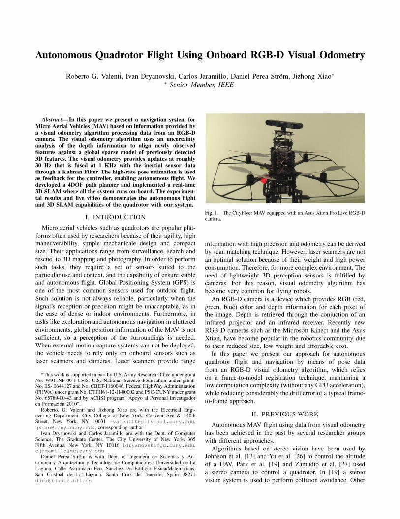
Fig. 1. The CityFlyer MAV equipped with an Asus Xtion Pro Live RGB-Dcamera.
information with high precision and odometry can be derivedby scan matching technique. However, laser scanners are notan optimal solution because of their weight and high powerconsumption. Therefore, for more complex environment, Theneed of lightweight 3D perception sensors is fulfilled bycameras. For this reason, visual odometry algorithm hasbecome very common for flying robots.
An RGB-D camera is a device which provides RGB (red,green, blue) color and depth information for each pixel ofthe image. Depth is retrieved through the conjuction of aninfrared projector and an infrared receiver. Recently newRGB-D cameras such as the Microsoft Kinect and the AsusXtion, have become popular in the robotics community dueto their reduced size, low weight and affordable cost.
In this paper we present our approach for autonomousquadrotor flight and navigation by means of pose datafrom an RGB-D visual odometry algorithm, which relieson a frame-to-model registration technique, mantaining alow computation complexity (without any GPU acceleration),while reducing considerably the drift error of a typical frame-to-frame approach.
II. PREVIOUS WORK
Autonomous MAV flight using data from visual odometryhas been achieved in the past by several researcher groupswith different approaches.
Algorithms based on stereo vision have been used byJohnson et al. [13] and Yu et al. [26] to control the altitudeof a UAV. Park et al. [19] and Zamudio et al. [27] useda stereo camera to control a quadrotor. In [19] a stereovision system is used to perform collision avoidance. Other
strategies using monocular vision, which better meet theneeds of a limited payload of a MAV, have been adopted.Achtelick et al [1] controlled a quadrotor for both indoorand outdoor flight by using visual information coming froma single camera pointing down, where depth information wasrecoverred by fusing a pressure sensor and an accelerometerthrough an Extended Kalman Filter. A similar system ispresented by Blosch et al. [3] to perform indoor explorationwith a MAV (with the difference that it does not rely on anyother exteroceptive sensor). Conroy et al. [5] and Zingg et al.[28], present a biologically inspired vision system for safeand stable corridor navigation of a MAV based on opticalflow from an omnidirectional camera. Rondon et al. [22]present a monocular vision system to estimate and controlaltitute, lateral position and forward velocity of a MAV viaoptical flow.
In order to perform several tasks with the same platform,both monocular and stereo vision techniques have beenadopted. For instance Hrabar et al. [11] combine stereo visionfrom a forward-facing camera pair and optical flow fromtwo sideways-looking monocular cameras in order to avoidobstacles and navigate inside a canyon with maximum clear-ance. Meier et al. [17] and Fraundorfer et al. [9] integrate adown-facing monocular camera with a forward-facing stereocamera for flight control and obstacle avoidance. For a morerobust navigation in different environments, visual odometryis sometimes fused with other exteroceptive position sensors.In the work by Tomic et al. [14] and Bachrach et al. [2],a quadrotor is equipped with a laser range-finder and astereo camera to enable stable flight and SLAM in a numberof large-scale, GPS-denied environments, such as an urbancanyon.
Unlike visual odometry from standard cameras, RGB-Dvisual odometry has not been widely used by researchers tocontrol a flying robot. Stowers et al. [24] presented one ofthe first results of using RGB-D camera for real-time robot-control application. They use a Kinect pointed towards theground to estimate and control the height of a quadrotor.The work presented by Huang et al. [12] is the most closelyrelated to ours. They use a RGB-D visual-odometry (basedon standard stereo visual odometry) to control a MAV inunknown indoor environments and do mapping. The poseestimation runs on the onboard computer while mapping andloop closure runs on an off-board computer.
In our proposed system, we use a recently developed visualodometry algorithm, able to reduce the drift error thanks to afast frame-to-model approach. Further, all the components ofthe system (including mapping and loop closure) run onboardon the same kind of computer as the system proposed byHuang et al. [12].
III. SYSTEM ARCHITECTURE
The platform we use for our experiments is an AscTecPelican quadrotor [10], on which we mounted an AsusXtion Pro Live. The quadrotor is equipped with a 1.86GHz Core2Duo processor with 4GB of RAM and a FlightControl Unit (FCU) board with 2 ARM7 microcontrollers,
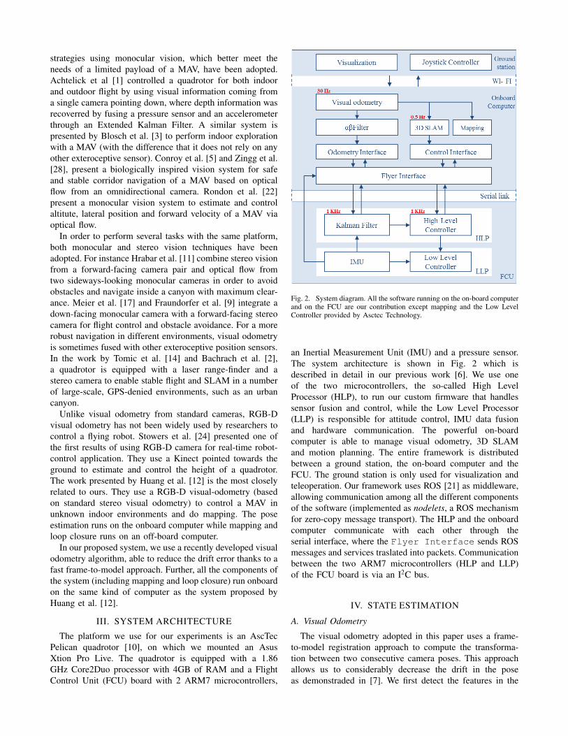
Fig. 2. System diagram. All the software running on the on-board computerand on the FCU are our contribution except mapping and the Low LevelController provided by Asctec Technology.
an Inertial Measurement Unit (IMU) and a pressure sensor.The system architecture is shown in Fig. 2 which isdescribed in detail in our previous work [6]. We use oneof the two microcontrollers, the so-called High LevelProcessor (HLP), to run our custom firmware that handlessensor fusion and control, while the Low Level Processor(LLP) is responsible for attitude control, IMU data fusionand hardware communication. The powerful on-boardcomputer is able to manage visual odometry, 3D SLAMand motion planning. The entire framework is distributedbetween a ground station, the on-board computer and theFCU. The ground station is only used for visualization andteleoperation. Our framework uses ROS [21] as middleware,allowing communication among all the different componentsof the software (implemented as nodelets, a ROS mechanismfor zero-copy message transport). The HLP and the onboardcomputer communicate with each other through theserial interface, where the Flyer Interface sends ROSmessages and services traslated into packets. Communicationbetween the two ARM7 microcontrollers (HLP and LLP)of the FCU board is via an I2C bus.
IV. STATE ESTIMATION
A. Visual Odometry
The visual odometry adopted in this paper uses a frame-to-model registration approach to compute the transforma-tion between two consecutive camera poses. This approachallows us to considerably decrease the drift in the poseas demonstraded in [7]. We first detect the features in the
captured scene by using Shi-Tomasi [23] algorithm and their3D coordinates in the camera frame, then we align thesefeatures against a global model of 3D features (previouslydetected). We perform data association and filtering usinga probabilistic method, which employs a novel uncertaintyestimation based on a Gaussian mixture model (described inour previous work [7]). We use this 3D normal distributionmodel for each feature detected in the incoming RGB-Dimage. This set of 3D features (with mean and covariancematrix µ and Σ), is expressed with respect to the camerareference frame. We refer to this set as Data. We have asimilar set that we call Model and is expressed in the fixedframe. We use ICP [4] to align Data against Model andthen it is transformed into the fixed frame. The alignmentproduces the transformation T, composed by a Rotationmatrix R and a translation vector t. We also need to expressthe mean and the covariance matrix of each feature in Datawith respect to the fixed frame. We can do so according to:
µ′
= Rµ+ t (1a)
Σ′
= RΣRT . (1b)
Once we have Data expressed in the fixed frame we generatecorrespondences adopting the following steps. First we builda Kd-tree [18] of the Model, and then for each feature ofData we find k nearest Euclidean neighbors from the Model.Next, for each point d
′
i of the transformed Data, we computethe Mahalanobis distance between the point and its nearestneighbor in the Model, mj .
dist(d′,m) =
√∆d′m(Σ[M ] + Σ[D′ ])−1∆T
d′m(2)
If this distance is lower than a certain threshold, the twopoints are associated establishing the correspondence. Allthe points which cannot be associated are inserted in theModel. The update is performed by a Kalman Filter, whichtakes the Model and its covariance matrix Σ as predictionand updates it with the new features and their covariances(for more details refer to [7]). In order to guarantee costant-time performance, we constrain the model’s maximum size.If the model grows beyond a certain upper bound, the oldestfeatures are discarded and overwritten with the new ones.
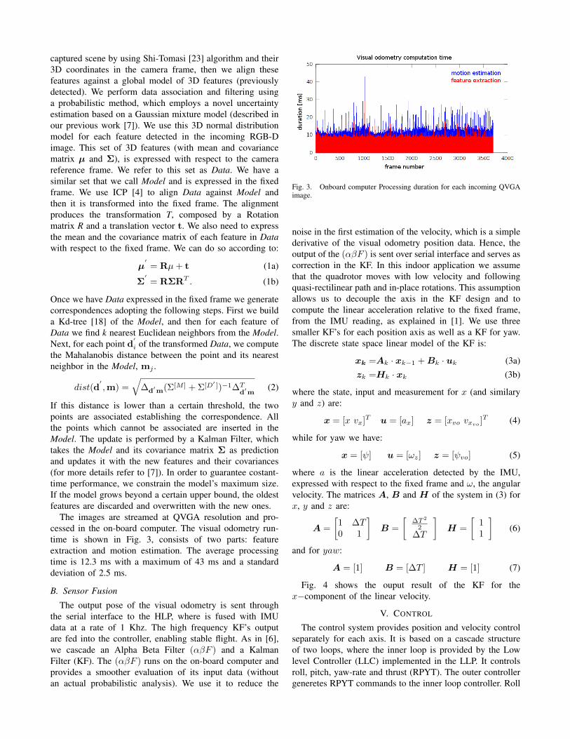
The images are streamed at QVGA resolution and pro-cessed in the on-board computer. The visual odometry run-time is shown in Fig. 3, consists of two parts: featureextraction and motion estimation. The average processingtime is 12.3 ms with a maximum of 43 ms and a standarddeviation of 2.5 ms.
B. Sensor Fusion
The output pose of the visual odometry is sent throughthe serial interface to the HLP, where is fused with IMUdata at a rate of 1 Khz. The high frequency KF’s outputare fed into the controller, enabling stable flight. As in [6],we cascade an Alpha Beta Filter (αβF ) and a KalmanFilter (KF). The (αβF ) runs on the on-board computer andprovides a smoother evaluation of its input data (withoutan actual probabilistic analysis). We use it to reduce the
Fig. 3. Onboard computer Processing duration for each incoming QVGAimage.
noise in the first estimation of the velocity, which is a simplederivative of the visual odometry position data. Hence, theoutput of the (αβF ) is sent over serial interface and serves ascorrection in the KF. In this indoor application we assumethat the quadrotor moves with low velocity and followingquasi-rectilinear path and in-place rotations. This assumptionallows us to decouple the axis in the KF design and tocompute the linear acceleration relative to the fixed frame,from the IMU reading, as explained in [1]. We use threesmaller KF’s for each position axis as well as a KF for yaw.The discrete state space linear model of the KF is:
xk =Ak · xk−1 +Bk · uk (3a)zk =Hk · xk (3b)
where the state, input and measurement for x (and similaryy and z) are:
x = [x vx]T u = [ax] z = [xvo vxvo]T (4)
while for yaw we have:
x = [ψ] u = [ωz] z = [ψvo] (5)
where a is the linear acceleration detected by the IMU,expressed with respect to the fixed frame and ω, the angularvelocity. The matrices A, B and H of the system in (3) forx, y and z are:
A =
[1 ∆T0 1
]B =
[∆T 2
2∆T
]H =
[11
](6)
and for yaw:
A = [1] B = [∆T ] H = [1] (7)
Fig. 4 shows the ouput result of the KF for thex−component of the linear velocity.
V. CONTROL
The control system provides position and velocity controlseparately for each axis. It is based on a cascade structureof two loops, where the inner loop is provided by the Lowlevel Controller (LLC) implemented in the LLP. It controlsroll, pitch, yaw-rate and thrust (RPYT). The outer controllergeneretes RPYT commands to the inner loop controller. Roll
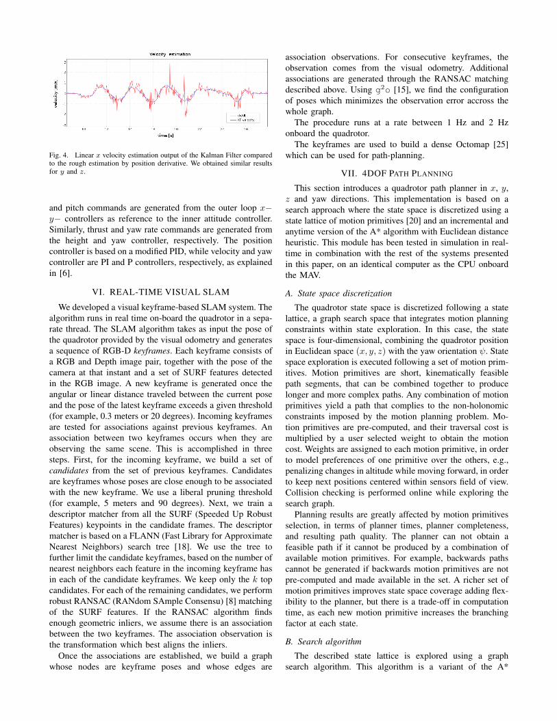
Fig. 4. Linear x velocity estimation output of the Kalman Filter comparedto the rough estimation by position derivative. We obtained similar resultsfor y and z.
and pitch commands are generated from the outer loop x−y− controllers as reference to the inner attitude controller.Similarly, thrust and yaw rate commands are generated fromthe height and yaw controller, respectively. The positioncontroller is based on a modified PID, while velocity and yawcontroller are PI and P controllers, respectively, as explainedin [6].
VI. REAL-TIME VISUAL SLAM
We developed a visual keyframe-based SLAM system. Thealgorithm runs in real time on-board the quadrotor in a sepa-rate thread. The SLAM algorithm takes as input the pose ofthe quadrotor provided by the visual odometry and generatesa sequence of RGB-D keyframes. Each keyframe consists ofa RGB and Depth image pair, together with the pose of thecamera at that instant and a set of SURF features detectedin the RGB image. A new keyframe is generated once theangular or linear distance traveled between the current poseand the pose of the latest keyframe exceeds a given threshold(for example, 0.3 meters or 20 degrees). Incoming keyframesare tested for associations against previous keyframes. Anassociation between two keyframes occurs when they areobserving the same scene. This is accomplished in threesteps. First, for the incoming keyframe, we build a set ofcandidates from the set of previous keyframes. Candidatesare keyframes whose poses are close enough to be associatedwith the new keyframe. We use a liberal pruning threshold(for example, 5 meters and 90 degrees). Next, we train adescriptor matcher from all the SURF (Speeded Up RobustFeatures) keypoints in the candidate frames. The descriptormatcher is based on a FLANN (Fast Library for ApproximateNearest Neighbors) search tree [18]. We use the tree tofurther limit the candidate keyframes, based on the number ofnearest neighbors each feature in the incoming keyframe hasin each of the candidate keyframes. We keep only the k topcandidates. For each of the remaining candidates, we performrobust RANSAC (RANdom SAmple Consensu) [8] matchingof the SURF features. If the RANSAC algorithm findsenough geometric inliers, we assume there is an associationbetween the two keyframes. The association observation isthe transformation which best aligns the inliers.
Once the associations are established, we build a graphwhose nodes are keyframe poses and whose edges are
association observations. For consecutive keyframes, theobservation comes from the visual odometry. Additionalassociations are generated through the RANSAC matchingdescribed above. Using g2o [15], we find the configurationof poses which minimizes the observation error accross thewhole graph.
The procedure runs at a rate between 1 Hz and 2 Hzonboard the quadrotor.
The keyframes are used to build a dense Octomap [25]which can be used for path-planning.
VII. 4DOF PATH PLANNING
This section introduces a quadrotor path planner in x, y,z and yaw directions. This implementation is based on asearch approach where the state space is discretized using astate lattice of motion primitives [20] and an incremental andanytime version of the A* algorithm with Euclidean distanceheuristic. This module has been tested in simulation in real-time in combination with the rest of the systems presentedin this paper, on an identical computer as the CPU onboardthe MAV.
A. State space discretization
The quadrotor state space is discretized following a statelattice, a graph search space that integrates motion planningconstraints within state exploration. In this case, the statespace is four-dimensional, combining the quadrotor positionin Euclidean space (x, y, z) with the yaw orientation ψ. Statespace exploration is executed following a set of motion prim-itives. Motion primitives are short, kinematically feasiblepath segments, that can be combined together to producelonger and more complex paths. Any combination of motionprimitives yield a path that complies to the non-holonomicconstraints imposed by the motion planning problem. Mo-tion primitives are pre-computed, and their traversal cost ismultiplied by a user selected weight to obtain the motioncost. Weights are assigned to each motion primitive, in orderto model preferences of one primitive over the others, e.g.,penalizing changes in altitude while moving forward, in orderto keep next positions centered within sensors field of view.Collision checking is performed online while exploring thesearch graph.
Planning results are greatly affected by motion primitivesselection, in terms of planner times, planner completeness,and resulting path quality. The planner can not obtain afeasible path if it cannot be produced by a combination ofavailable motion primitives. For example, backwards pathscannot be generated if backwards motion primitives are notpre-computed and made available in the set. A richer set ofmotion primitives improves state space coverage adding flex-ibility to the planner, but there is a trade-off in computationtime, as each new motion primitive increases the branchingfactor at each state.
B. Search algorithm
The described state lattice is explored using a graphsearch algorithm. This algorithm is a variant of the A*
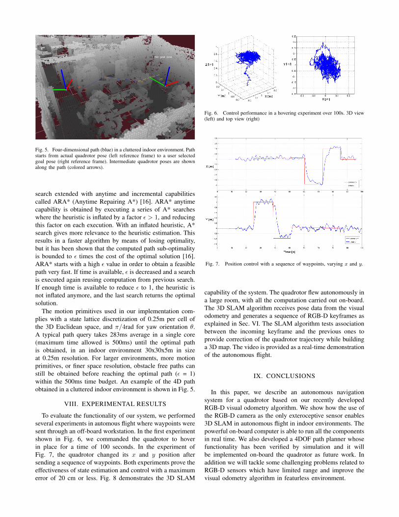
Fig. 5. Four-dimensional path (blue) in a cluttered indoor environment. Pathstarts from actual quadrotor pose (left reference frame) to a user selectedgoal pose (right reference frame). Intermediate quadrotor poses are shownalong the path (colored arrows).
search extended with anytime and incremental capabilitiescalled ARA* (Anytime Repairing A*) [16]. ARA* anytimecapability is obtained by executing a series of A* searcheswhere the heuristic is inflated by a factor ε > 1, and reducingthis factor on each execution. With an inflated heuristic, A*search gives more relevance to the heuristic estimation. Thisresults in a faster algorithm by means of losing optimality,but it has been shown that the computed path sub-optimalityis bounded to ε times the cost of the optimal solution [16].ARA* starts with a high ε value in order to obtain a feasiblepath very fast. If time is available, ε is decreased and a searchis executed again reusing computation from previous search.If enough time is available to reduce ε to 1, the heuristic isnot inflated anymore, and the last search returns the optimalsolution.
The motion primitives used in our implementation com-plies with a state lattice discretization of 0.25m per cell ofthe 3D Euclidean space, and π/4rad for yaw orientation θ.A typical path query takes 283ms average in a single core(maximum time allowed is 500ms) until the optimal pathis obtained, in an indoor environment 30x30x5m in sizeat 0.25m resolution. For larger environments, more motionprimitives, or finer space resolution, obstacle free paths canstill be obtained before reaching the optimal path (ε = 1)within the 500ms time budget. An example of the 4D pathobtained in a cluttered indoor environment is shown in Fig. 5.
VIII. EXPERIMENTAL RESULTS
To evaluate the functionality of our system, we performedseveral experiments in automous flight where waypoints weresent through an off-board workstation. In the first experimentshown in Fig. 6, we commanded the quadrotor to hoverin place for a time of 100 seconds. In the experiment ofFig. 7, the quadrotor changed its x and y position aftersending a sequence of waypoints. Both experiments prove theeffectiveness of state estimation and control with a maximumerror of 20 cm or less. Fig. 8 demonstrates the 3D SLAM
Fig. 6. Control performance in a hovering experiment over 100s. 3D view(left) and top view (right)
Fig. 7. Position control with a sequence of waypoints, varying x and y.
capability of the system. The quadrotor flew autonomously ina large room, with all the computation carried out on-board.The 3D SLAM algorithm receives pose data from the visualodometry and generates a sequence of RGB-D keyframes asexplained in Sec. VI. The SLAM algorithm tests associationbetween the incoming keyframe and the previous ones toprovide correction of the quadrotor trajectory while buildinga 3D map. The video is provided as a real-time demonstrationof the autonomous flight.
IX. CONCLUSIONS
In this paper, we describe an autonomous navigationsystem for a quadrotor based on our recently developedRGB-D visual odometry algorithm. We show how the use ofthe RGB-D camera as the only exteroceptive sensor enables3D SLAM in autonomous flight in indoor environments. Thepowerful on-board computer is able to run all the componentsin real time. We also developed a 4DOF path planner whosefunctionality has been verified by simulation and it willbe implemented on-board the quadrotor as future work. Inaddition we will tackle some challenging problems related toRGB-D sensors which have limited range and improve thevisual odometry algorithm in featurless environment.
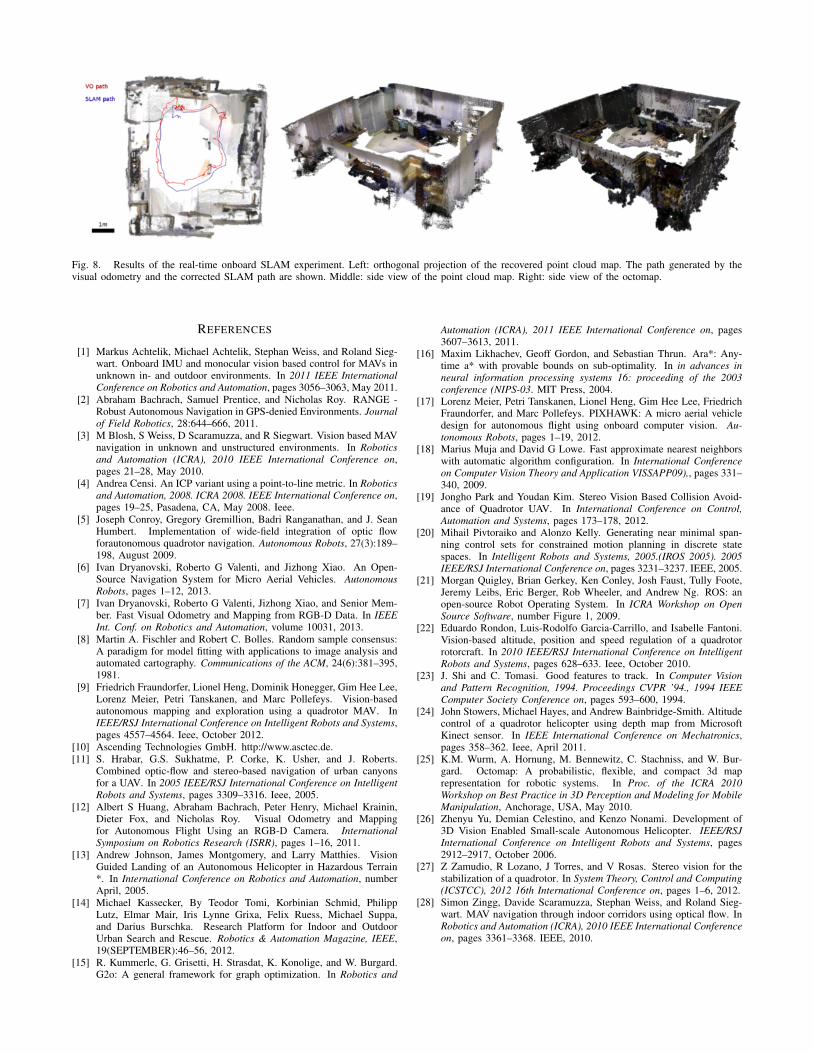
Fig. 8. Results of the real-time onboard SLAM experiment. Left: orthogonal projection of the recovered point cloud map. The path generated by thevisual odometry and the corrected SLAM path are shown. Middle: side view of the point cloud map. Right: side view of the octomap.
REFERENCES
[1] Markus Achtelik, Michael Achtelik, Stephan Weiss, and Roland Sieg-wart. Onboard IMU and monocular vision based control for MAVs inunknown in- and outdoor environments. In 2011 IEEE InternationalConference on Robotics and Automation, pages 3056–3063, May 2011.
[2] Abraham Bachrach, Samuel Prentice, and Nicholas Roy. RANGE -Robust Autonomous Navigation in GPS-denied Environments. Journalof Field Robotics, 28:644–666, 2011.
[3] M Blosh, S Weiss, D Scaramuzza, and R Siegwart. Vision based MAVnavigation in unknown and unstructured environments. In Roboticsand Automation (ICRA), 2010 IEEE International Conference on,pages 21–28, May 2010.
[4] Andrea Censi. An ICP variant using a point-to-line metric. In Roboticsand Automation, 2008. ICRA 2008. IEEE International Conference on,pages 19–25, Pasadena, CA, May 2008. Ieee.
[5] Joseph Conroy, Gregory Gremillion, Badri Ranganathan, and J. SeanHumbert. Implementation of wide-field integration of optic flowforautonomous quadrotor navigation. Autonomous Robots, 27(3):189–198, August 2009.
[6] Ivan Dryanovski, Roberto G Valenti, and Jizhong Xiao. An Open-Source Navigation System for Micro Aerial Vehicles. AutonomousRobots, pages 1–12, 2013.
[7] Ivan Dryanovski, Roberto G Valenti, Jizhong Xiao, and Senior Mem-ber. Fast Visual Odometry and Mapping from RGB-D Data. In IEEEInt. Conf. on Robotics and Automation, volume 10031, 2013.
[8] Martin A. Fischler and Robert C. Bolles. Random sample consensus:A paradigm for model fitting with applications to image analysis andautomated cartography. Communications of the ACM, 24(6):381–395,1981.
[9] Friedrich Fraundorfer, Lionel Heng, Dominik Honegger, Gim Hee Lee,Lorenz Meier, Petri Tanskanen, and Marc Pollefeys. Vision-basedautonomous mapping and exploration using a quadrotor MAV. InIEEE/RSJ International Conference on Intelligent Robots and Systems,pages 4557–4564. Ieee, October 2012.
[10] Ascending Technologies GmbH. http://www.asctec.de.[11] S. Hrabar, G.S. Sukhatme, P. Corke, K. Usher, and J. Roberts.
Combined optic-flow and stereo-based navigation of urban canyonsfor a UAV. In 2005 IEEE/RSJ International Conference on IntelligentRobots and Systems, pages 3309–3316. Ieee, 2005.
[12] Albert S Huang, Abraham Bachrach, Peter Henry, Michael Krainin,Dieter Fox, and Nicholas Roy. Visual Odometry and Mappingfor Autonomous Flight Using an RGB-D Camera. InternationalSymposium on Robotics Research (ISRR), pages 1–16, 2011.
[13] Andrew Johnson, James Montgomery, and Larry Matthies. VisionGuided Landing of an Autonomous Helicopter in Hazardous Terrain*. In International Conference on Robotics and Automation, numberApril, 2005.
[14] Michael Kassecker, By Teodor Tomi, Korbinian Schmid, PhilippLutz, Elmar Mair, Iris Lynne Grixa, Felix Ruess, Michael Suppa,and Darius Burschka. Research Platform for Indoor and OutdoorUrban Search and Rescue. Robotics & Automation Magazine, IEEE,19(SEPTEMBER):46–56, 2012.
[15] R. Kummerle, G. Grisetti, H. Strasdat, K. Konolige, and W. Burgard.G2o: A general framework for graph optimization. In Robotics and
Automation (ICRA), 2011 IEEE International Conference on, pages3607–3613, 2011.
[16] Maxim Likhachev, Geoff Gordon, and Sebastian Thrun. Ara*: Any-time a* with provable bounds on sub-optimality. In in advances inneural information processing systems 16: proceeding of the 2003conference (NIPS-03. MIT Press, 2004.
[17] Lorenz Meier, Petri Tanskanen, Lionel Heng, Gim Hee Lee, FriedrichFraundorfer, and Marc Pollefeys. PIXHAWK: A micro aerial vehicledesign for autonomous flight using onboard computer vision. Au-tonomous Robots, pages 1–19, 2012.
[18] Marius Muja and David G Lowe. Fast approximate nearest neighborswith automatic algorithm configuration. In International Conferenceon Computer Vision Theory and Application VISSAPP09),, pages 331–340, 2009.
[19] Jongho Park and Youdan Kim. Stereo Vision Based Collision Avoid-ance of Quadrotor UAV. In International Conference on Control,Automation and Systems, pages 173–178, 2012.
[20] Mihail Pivtoraiko and Alonzo Kelly. Generating near minimal span-ning control sets for constrained motion planning in discrete statespaces. In Intelligent Robots and Systems, 2005.(IROS 2005). 2005IEEE/RSJ International Conference on, pages 3231–3237. IEEE, 2005.
[21] Morgan Quigley, Brian Gerkey, Ken Conley, Josh Faust, Tully Foote,Jeremy Leibs, Eric Berger, Rob Wheeler, and Andrew Ng. ROS: anopen-source Robot Operating System. In ICRA Workshop on OpenSource Software, number Figure 1, 2009.
[22] Eduardo Rondon, Luis-Rodolfo Garcia-Carrillo, and Isabelle Fantoni.Vision-based altitude, position and speed regulation of a quadrotorrotorcraft. In 2010 IEEE/RSJ International Conference on IntelligentRobots and Systems, pages 628–633. Ieee, October 2010.
[23] J. Shi and C. Tomasi. Good features to track. In Computer Visionand Pattern Recognition, 1994. Proceedings CVPR ’94., 1994 IEEEComputer Society Conference on, pages 593–600, 1994.
[24] John Stowers, Michael Hayes, and Andrew Bainbridge-Smith. Altitudecontrol of a quadrotor helicopter using depth map from MicrosoftKinect sensor. In IEEE International Conference on Mechatronics,pages 358–362. Ieee, April 2011.
[25] K.M. Wurm, A. Hornung, M. Bennewitz, C. Stachniss, and W. Bur-gard. Octomap: A probabilistic, flexible, and compact 3d maprepresentation for robotic systems. In Proc. of the ICRA 2010Workshop on Best Practice in 3D Perception and Modeling for MobileManipulation, Anchorage, USA, May 2010.
[26] Zhenyu Yu, Demian Celestino, and Kenzo Nonami. Development of3D Vision Enabled Small-scale Autonomous Helicopter. IEEE/RSJInternational Conference on Intelligent Robots and Systems, pages2912–2917, October 2006.
[27] Z Zamudio, R Lozano, J Torres, and V Rosas. Stereo vision for thestabilization of a quadrotor. In System Theory, Control and Computing(ICSTCC), 2012 16th International Conference on, pages 1–6, 2012.
[28] Simon Zingg, Davide Scaramuzza, Stephan Weiss, and Roland Sieg-wart. MAV navigation through indoor corridors using optical flow. InRobotics and Automation (ICRA), 2010 IEEE International Conferenceon, pages 3361–3368. IEEE, 2010.