av surround receiver avr-5700
TRANSCRIPT
AV SURROUND RECEIVER
AVR-5700OPERATING INSTRUCTIONS
DSPSIMULATION
MASTER VOLUME
REMOTE SENSOR
ON / STANDBY
ON / STANDBY
OFF
INPUT SELECTOR
TAPE-2 MONHOME
THX CINEMA
VOLUME LEVEL
TUNER DVD VDP TV / DBS VCR-1 VCR-2 V. AUX MD / TAPE-1 TAPE-2 MONPHONOSURROUND SPEAKER
CDBA
L C R
SL S SR
CH INDICATORLOCK
LFE
PHONES
BASS TREBLE
DIRECT
INPUT MODE
STEREO
ANALOG
DOLBY / DTSSURROUND
WIDESCREEN
5CHSTEREO
SURROUND MODE CHANNEL VOLUME
SELECT
6CHEXT. IN
VIDEOSELECT
TONEDEFEAT DIMMERPANEL MODE
DOWN UP
SOURCE
INPUT REC / MULTI
DVD
START LEARNED/TX
HOME THX CINEMA
TUNING
BANDTITLE MENU/GUIDE
MODE
MEMORY
USE/LEARN T.TONE MULTI SET UP
RETURN
PANEL
DISPLAY
ON SCREEN
DOLBY / DTSSURROUND DIRECT
DSP SIMULATION 5CH STEREO STEREO
INPUT MODE ANALOG EXT.IN
MUTING
MASTER VOL.
VOLUME DISC SKIP+
SYSTEM CALL POWER
VDP TUNER SHIFT
TV/DBS V.AUX PHONO
VCR-1 CD MD / TAPE-1 CHANNEL
VCR-2 TAPE-2 MON TV/VCR
AVR/AVC VIDEO DVD TV
AUDIO
VDP VCR
CDMD
LOCKDECK
SYSTEMSETUP
SURROUNDPARAMETER
CH SELECT
SELECT
RC-853
1 2 3
4
SET
A / B
CALL OFF
ENTER
ON / SOURCE
5 6
7 8 9
+10 0
AVR-5700PRECISION AUDIO COMPONENT / AV SURROUND RECEIVER
“SERIAL NO.
PLEASE RECORD UNIT SERIAL NUMBER ATTACHED TO THE REAR OF THE
CABINET FOR FUTURE REFERENCE”
2 We greatly appreciate your purchase of the AVR-5700.
2 To be sure you take maximum advantage of all the features the AVR-5700 has to offer, read these instructions
carefully and use the set properly. Be sure to keep this manual for future reference should any questions or
problems arise.
2
2 SAFETY PRECAUTIONS
CAUTION
RISK OF ELECTRIC SHOCK
DO NOT OPEN
CAUTION: TO REDUCE THE RISK OF ELECTRIC SHOCK, DO NOT
REMOVE COVER (OR BACK). NO USER-SERVICEABLE PARTS INSIDE.
REFER SERVICING TO QUALIFIED SERVICE PERSONNEL.
The lightning flash with arrowhead symbol, within anequilateral triangle, is intended to alert the user to thepresence of uninsulated “dangerous voltage” within theproduct’s enclosure that may be of sufficient magnitude toconstitute a risk of electric shock to persons.
The exclamation point within an equilateral triangle isintended to alert the user to the presence of importantoperating and maintenance (servicing) instructions in theliterature accompanying the appliance.
CAUTION
TO PREVENT ELECTRIC SHOCK DO NOT USE THIS (POLARIZED) PLUGWITH AN EXTENSION CORD, RECEPTACLE OR OTHER OUTLET UNLESSTHE BLADES CAN BE FULLY INSERTED TO PREVENT BLADEEXPOSURE.
ATTENTION
POUR PREVENIR LES CHOCS ELECTRIQUES NE PAS UTILISER CETTEFICHE POLARISEE AVEC UN PROLONGATEUR UNE PRISE DE COURANTOU UNE AUTRE SORTIE DE COURANT, SAUF SI LES LAMES PEUVENTETRE INSEREES A FOND SANS EN LAISSER AUCUNE PARTIE ADECOUVERT.
This device complies with Part 15 of the FCC Rules. Operation is subject tothe following two conditions: (1) This device may not cause harmfulinterference, and (2) this device must accept any interference received,including interference that may cause undesired operation.
This Class B digital apparatus meets all requirements of the CanadianInterference-Causing Equipment Regulations.
Cet appareil numérique de la classe B respecte toutes les exigences duRèglement sur le matériel brouilleur du Canada.
WARNING: TO REDUCE THE RISK OF FIRE OR ELECTRIC SHOCK, DO
NOT EXPOSE THIS APPLIANCE TO RAIN OR MOISTURE.
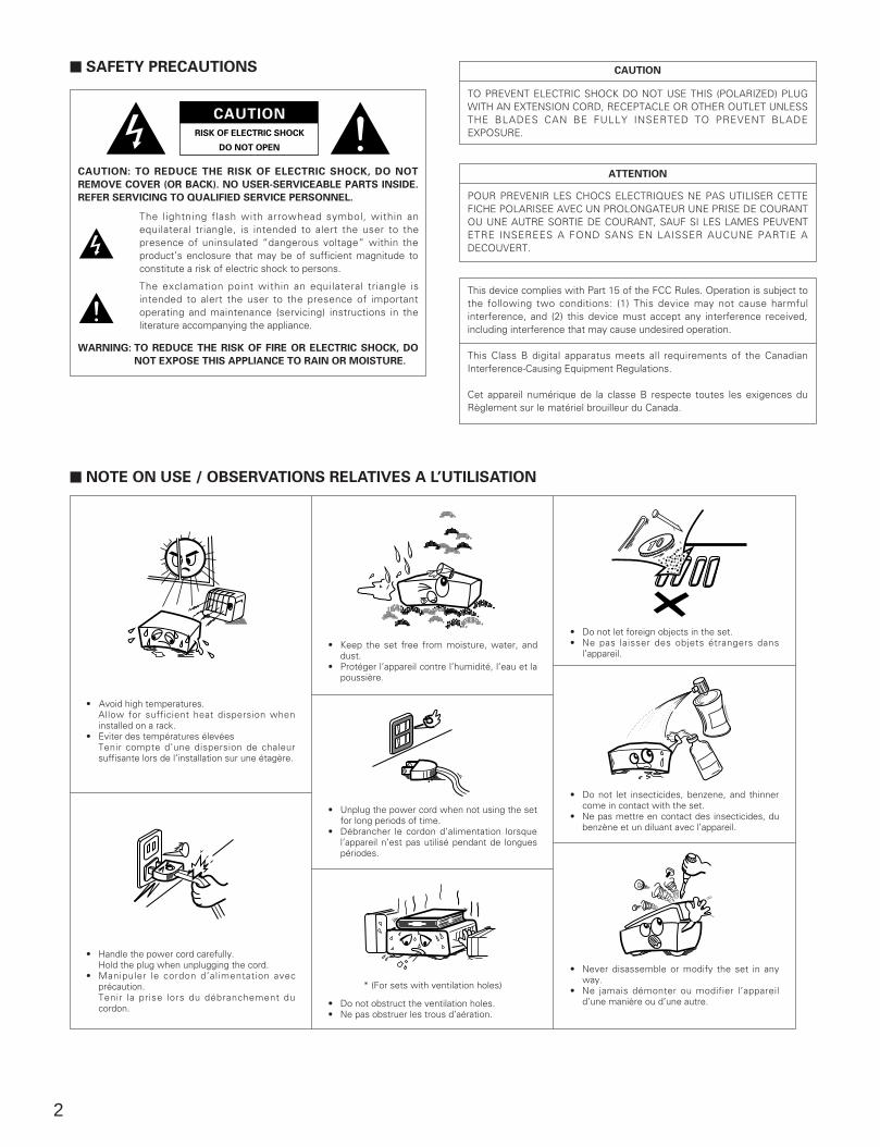
2 NOTE ON USE / OBSERVATIONS RELATIVES A L’UTILISATION
• Avoid high temperatures.Allow for sufficient heat dispersion wheninstalled on a rack.
• Eviter des températures élevées Tenir compte d’une dispersion de chaleursuffisante lors de l’installation sur une étagère.
• Keep the set free from moisture, water, anddust.
• Protéger l’appareil contre l’humidité, l’eau et lapoussière.
• Do not let foreign objects in the set.• Ne pas laisser des objets étrangers dans
l’appareil.
• Do not let insecticides, benzene, and thinnercome in contact with the set.
• Ne pas mettre en contact des insecticides, dubenzène et un diluant avec l’appareil.
• Never disassemble or modify the set in anyway.
• Ne jamais démonter ou modifier l’appareild’une manière ou d’une autre.
• Unplug the power cord when not using the setfor long periods of time.
• Débrancher le cordon d’alimentation lorsquel’appareil n’est pas utilisé pendant de longuespériodes.
* (For sets with ventilation holes)
• Do not obstruct the ventilation holes.• Ne pas obstruer les trous d’aération.
• Handle the power cord carefully.Hold the plug when unplugging the cord.
• Manipuler le cordon d’alimentation avecprécaution.Tenir la prise lors du débranchement ducordon.
3
SAFETY INSTRUCTIONS
1. Read Instructions – All the safety and operatinginstructions should be read before the appliance isoperated.
2. Retain Instructions – The safety and operating instructionsshould be retained for future reference.
3. Heed Warnings – All warnings on the appliance and in theoperating instructions should be adhered to.
4. Follow Instructions – All operating and use instructionsshould be followed.
5. Water and Moisture – The appliance should not be usednear water – for example, near a bathtub, washbowl,kitchen sink, laundry tub, in a wet basement, or near aswimming pool, and the like.
6. Carts and Stands – The appliance should be used only witha cart or stand that is recommended by the manufacturer.
6A. An appliance and cartcombination should bemoved with care.Quick stops, excessiveforce, and unevensurfaces may causethe appliance and cartcombination to overturn.
7. Wall or Ceiling Mounting – The appliance should bemounted to a wall or ceiling only as recommended by themanufacturer.
8. Ventilation – The appliance should be situated so that itslocation or position does not interfere with its properventilation. For example, the appliance should not besituated on a bed, sofa, rug, or similar surface that mayblock the ventilation openings; or, placed in a built-ininstallation, such as a bookcase or cabinet that mayimpede the flow of air through the ventilation openings.
9. Heat – The appliance should be situated away from heatsources such as radiators, heat registers, stoves, or otherappliances (including amplifiers) that produce heat.
10. Power Sources – The appliance should be connected to apower supply only of the type described in the operatinginstructions or as marked on the appliance.
11. Grounding or Polarization – Precautions should be taken sothat the grounding or polarization means of an appliance isnot defeated.
12. Power-Cord Protection – Power-supply cords should berouted so that they are not likely to be walked on orpinched by items placed upon or against them, payingparticular attention to cords at plugs, conveniencereceptacles, and the point where they exit from theappliance.
14. Cleaning – The appliance should be cleaned only asrecommended by the manufacturer.
15. Power Lines – An outdoor antenna should be located awayfrom power lines.
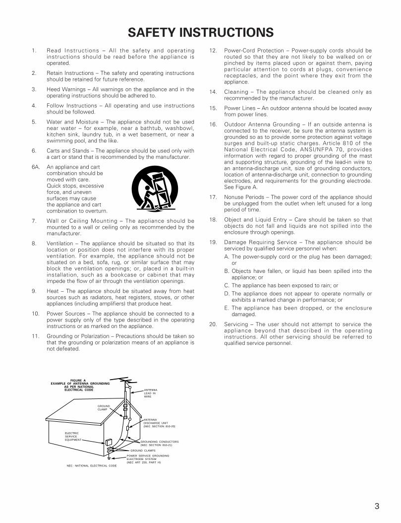
16. Outdoor Antenna Grounding – If an outside antenna isconnected to the receiver, be sure the antenna system isgrounded so as to provide some protection against voltagesurges and built-up static charges. Article 810 of theNational Electrical Code, ANSI/NFPA 70, providesinformation with regard to proper grounding of the mastand supporting structure, grounding of the lead-in wire toan antenna-discharge unit, size of grounding conductors,location of antenna-discharge unit, connection to groundingelectrodes, and requirements for the grounding electrode.See Figure A.
17. Nonuse Periods – The power cord of the appliance shouldbe unplugged from the outlet when left unused for a longperiod of time.
18. Object and Liquid Entry – Care should be taken so thatobjects do not fall and liquids are not spilled into theenclosure through openings.
19. Damage Requiring Service – The appliance should beserviced by qualified service personnel when: A. The power-supply cord or the plug has been damaged;
or B. Objects have fallen, or liquid has been spilled into the
appliance; orC. The appliance has been exposed to rain; orD. The appliance does not appear to operate normally or
exhibits a marked change in performance; or E. The appliance has been dropped, or the enclosure
damaged.
20. Servicing – The user should not attempt to service theappliance beyond that described in the operatinginstructions. All other servicing should be referred toqualified service personnel.
FIGURE AEXAMPLE OF ANTENNA GROUNDING
AS PER NATIONALELECTRICAL CODE ANTENNA
LEAD INWIRE
GROUNDCLAMP
ELECTRICSERVICEEQUIPMENT
ANTENNADISCHARGE UNIT(NEC SECTION 810-20)
GROUNDING CONDUCTORS(NEC SECTION 810-21)
GROUND CLAMPS
POWER SERVICE GROUNDINGELECTRODE SYSTEM(NEC ART 250, PART H)
NEC - NATIONAL ELECTRICAL CODE
4
2 INTRODUCTION
Thank you for choosing the DENON AVR-5700 Digital Surround A / V receiver. This remarkable component has been engineered to provide superb surround soundlistening with home theater sources such as DVD, as well as providing outstanding high fidelity reproduction of your favorite music sources.As this product is provided with an immense array of features, we recommend that before you begin hookup and operation that you review the contents of thismanual before proceeding.
TABLE OF CONTENTS
Before Using ……………………………………………………………………4
Cautions on Installation …………………………………………………………4
Cautions on Handling ……………………………………………………………5
Features …………………………………………………………………………5
Connections …………………………………………………………………6~13
Part Names and Functions ………………………………………………14, 15
Setting up the system ……………………………………………………16~27
Remote Control Unit ………………………………………………………28~36
Operation …………………………………………………………………36~42
Surround ……………………………………………………………………43~47
DSP Surround Simulation…………………………………………………48~51
Listening to the Radio ……………………………………………………52~54
Last Function Memory…………………………………………………………54
Initialization of the Microprocessor …………………………………………54
Troubleshooting ………………………………………………………………55
Additional Information ……………………………………………………56~61
Specifications …………………………………………………………………62
2 ACCESSORIES
Check that the following parts are included in addition to the main unit:
Q Operating instructions…..1 W Warranty ( for North America model only )………...........1 E Service station list…….....1 R AC cord.................……1
T Remote control unit Y R6P/AA batteries….....2 U AM loop antenna…...1 I FM indoor antenna…........1 O FM antenna adaptor….1
(RC-853)………………… ..1
1 BEFORE USING
Pay attention to the following before using this unit:
• Moving the setTo prevent short circuits or damaged wires in the connectioncords, always unplug the power cord and disconnect theconnection cords between all other audio components whenmoving the set.
• Before turning the power switch onCheck once again that all connections are proper and that there arenot problems with the connection cords. Always set the powerswitch to the standby position before connecting anddisconnecting connection cords.
• Store this instructions in a safe place.After reading, store this instructions along with the warranty in asafe place.
• Note that the illustrations in this instructions may differ fromthe actual set for explanation purposes.
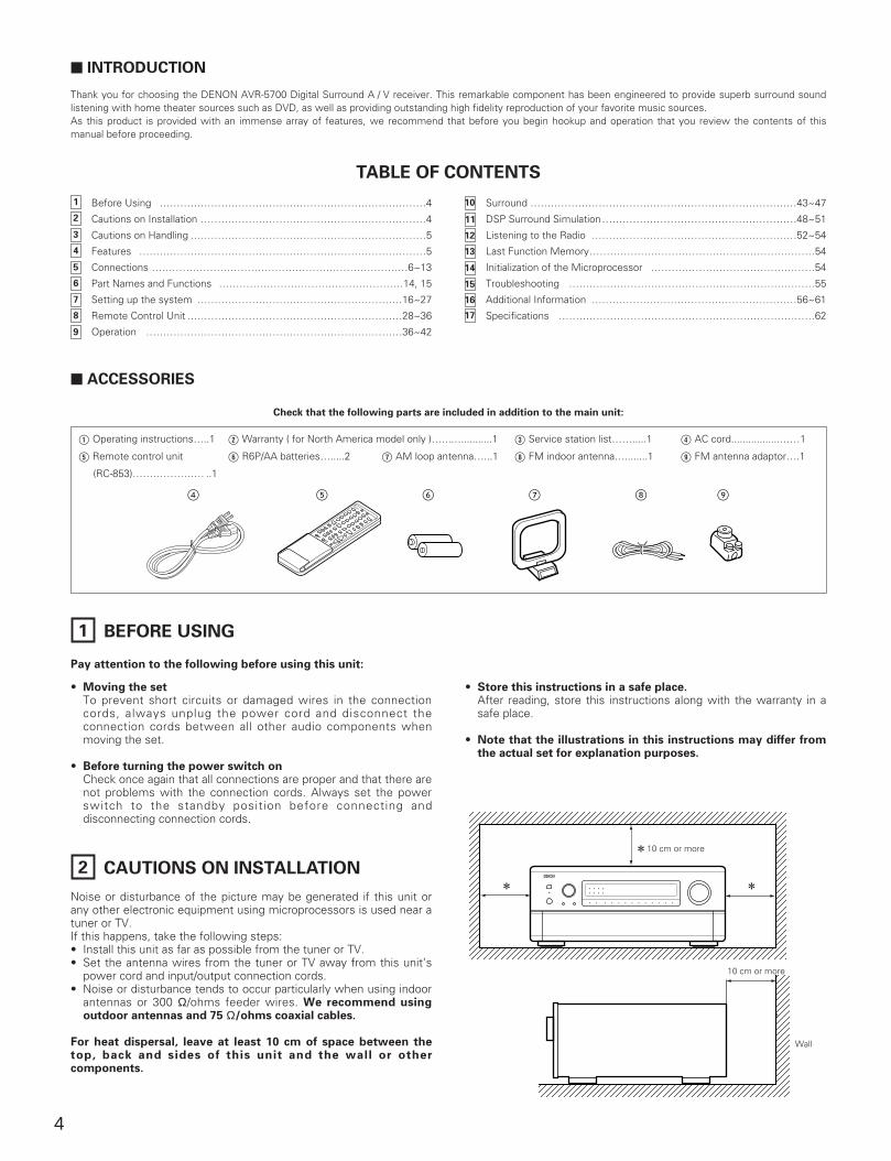
2 CAUTIONS ON INSTALLATION
Noise or disturbance of the picture may be generated if this unit orany other electronic equipment using microprocessors is used near atuner or TV.If this happens, take the following steps:• Install this unit as far as possible from the tuner or TV.• Set the antenna wires from the tuner or TV away from this unit’s
power cord and input/output connection cords.• Noise or disturbance tends to occur particularly when using indoor
antennas or 300 Ω/ohms feeder wires. We recommend usingoutdoor antennas and 75 Ω/ohms coaxial cables.
For heat dispersal, leave at least 10 cm of space between thetop, back and sides of this unit and the wall or othercomponents.
10 cm or more
2 10 cm or more
22
Wall
10 cm or more
1
2
5
4
7
3
6
8
9
10
11
12
13
14
15
16
17
5
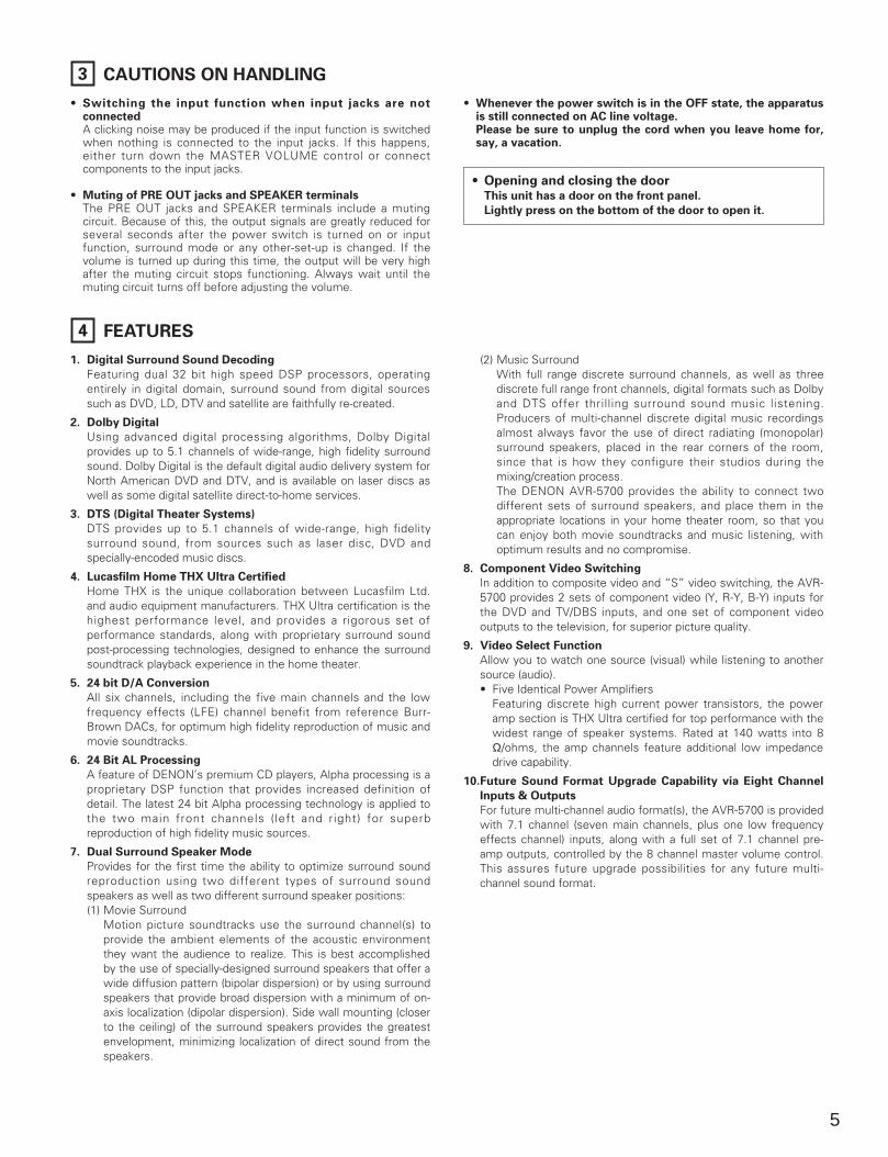
3 CAUTIONS ON HANDLING
• Switching the input function when input jacks are notconnected A clicking noise may be produced if the input function is switchedwhen nothing is connected to the input jacks. If this happens,either turn down the MASTER VOLUME control or connectcomponents to the input jacks.
• Muting of PRE OUT jacks and SPEAKER terminalsThe PRE OUT jacks and SPEAKER terminals include a mutingcircuit. Because of this, the output signals are greatly reduced forseveral seconds after the power switch is turned on or inputfunction, surround mode or any other-set-up is changed. If thevolume is turned up during this time, the output will be very highafter the muting circuit stops functioning. Always wait until themuting circuit turns off before adjusting the volume.
• Whenever the power switch is in the OFF state, the apparatusis still connected on AC line voltage.Please be sure to unplug the cord when you leave home for,say, a vacation.
4 FEATURES
1. Digital Surround Sound Decoding
Featuring dual 32 bit high speed DSP processors, operatingentirely in digital domain, surround sound from digital sourcessuch as DVD, LD, DTV and satellite are faithfully re-created.
2. Dolby Digital
Using advanced digital processing algorithms, Dolby Digitalprovides up to 5.1 channels of wide-range, high fidelity surroundsound. Dolby Digital is the default digital audio delivery system forNorth American DVD and DTV, and is available on laser discs aswell as some digital satellite direct-to-home services.
3. DTS (Digital Theater Systems)
DTS provides up to 5.1 channels of wide-range, high fidelitysurround sound, from sources such as laser disc, DVD andspecially-encoded music discs.
4. Lucasfilm Home THX Ultra Certified
Home THX is the unique collaboration between Lucasfilm Ltd.and audio equipment manufacturers. THX Ultra certification is thehighest performance level, and provides a rigorous set ofperformance standards, along with proprietary surround soundpost-processing technologies, designed to enhance the surroundsoundtrack playback experience in the home theater.
5. 24 bit D/A Conversion
All six channels, including the five main channels and the lowfrequency effects (LFE) channel benefit from reference Burr-Brown DACs, for optimum high fidelity reproduction of music andmovie soundtracks.
6. 24 Bit AL Processing
A feature of DENON’s premium CD players, Alpha processing is aproprietary DSP function that provides increased definition ofdetail. The latest 24 bit Alpha processing technology is applied tothe two main front channels ( left and right) for superbreproduction of high fidelity music sources.
7. Dual Surround Speaker Mode
Provides for the first time the ability to optimize surround soundreproduction using two different types of surround soundspeakers as well as two different surround speaker positions:(1) Movie Surround
Motion picture soundtracks use the surround channel(s) toprovide the ambient elements of the acoustic environmentthey want the audience to realize. This is best accomplishedby the use of specially-designed surround speakers that offer awide diffusion pattern (bipolar dispersion) or by using surroundspeakers that provide broad dispersion with a minimum of on-axis localization (dipolar dispersion). Side wall mounting (closerto the ceiling) of the surround speakers provides the greatestenvelopment, minimizing localization of direct sound from thespeakers.
(2) Music SurroundWith full range discrete surround channels, as well as threediscrete full range front channels, digital formats such as Dolbyand DTS offer thrilling surround sound music listening.Producers of multi-channel discrete digital music recordingsalmost always favor the use of direct radiating (monopolar)surround speakers, placed in the rear corners of the room,since that is how they configure their studios during themixing/creation process.The DENON AVR-5700 provides the ability to connect twodifferent sets of surround speakers, and place them in theappropriate locations in your home theater room, so that youcan enjoy both movie soundtracks and music listening, withoptimum results and no compromise.
8. Component Video Switching
In addition to composite video and “S” video switching, the AVR-5700 provides 2 sets of component video (Y, R-Y, B-Y) inputs forthe DVD and TV/DBS inputs, and one set of component videooutputs to the television, for superior picture quality.
9. Video Select Function
Allow you to watch one source (visual) while listening to anothersource (audio).• Five Identical Power Amplifiers
Featuring discrete high current power transistors, the poweramp section is THX Ultra certified for top performance with thewidest range of speaker systems. Rated at 140 watts into 8Ω/ohms, the amp channels feature additional low impedancedrive capability.
10.Future Sound Format Upgrade Capability via Eight Channel
Inputs & Outputs
For future multi-channel audio format(s), the AVR-5700 is providedwith 7.1 channel (seven main channels, plus one low frequencyeffects channel) inputs, along with a full set of 7.1 channel pre-amp outputs, controlled by the 8 channel master volume control.This assures future upgrade possibilities for any future multi-channel sound format.
• Opening and closing the doorThis unit has a door on the front panel.
Lightly press on the bottom of the door to open it.
6
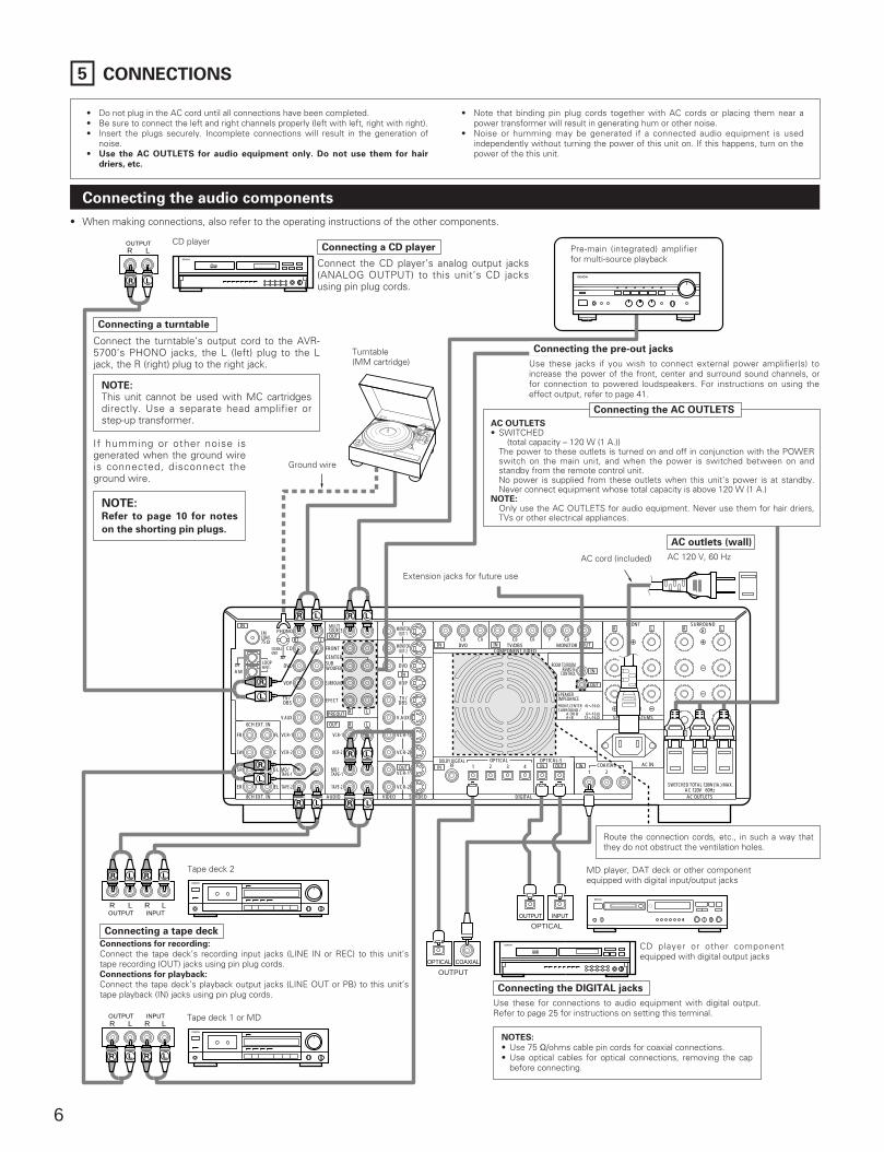
5 CONNECTIONS
• Do not plug in the AC cord until all connections have been completed.• Be sure to connect the left and right channels properly (left with left, right with right).• Insert the plugs securely. Incomplete connections will result in the generation of
noise.• Use the AC OUTLETS for audio equipment only. Do not use them for hair
driers, etc.
• Note that binding pin plug cords together with AC cords or placing them near apower transformer will result in generating hum or other noise.
• Noise or humming may be generated if a connected audio equipment is usedindependently without turning the power of this unit on. If this happens, turn on thepower of the this unit.
Connecting the audio components
A+B
OUT
OUT
OUT
OUT
OUT
OUT
PREOUT
6 16
PHONO
FRONT
CENTER
EFECT
SURROUND
SIGNALGND
CD
DVD
VDP
TV/ DBS
V.AUX
VCR-1
VCR-2
MD/ TAPE-1
TAPE-2
MONITORSOURCEMULTI
OUT-1
MONITOROUT-2
DVD
VDP
TV/DBS
V.AUX
VCR-1
VCR-2
VCR-1
VCR-2
VCR-1
VCR-2
MD/ TAPE-1
TAPE-2
6CH EXT. IN
FR
SW
SR
ER
FL
C
SL
EL
8CH EXT. IN AUDIO VIDEO S-VIDEO DIGITAL
SUBWOOFER
R L
R L
R L
R L Y CBDVD TV/DBS
COMPONENT VIDEO
SPEAKER SYSTEMS
OPTICALCOAXIAL
DOLBY DIGITALRF
OPTICAL-51 2 3
1 2 34
SWITCHED TOTAL 120W(1A.) MAX.AC 120V 60HzAC OUTLETS
AC IN
FRONT
CENTER
R L
R L
SURROUND
SURROUND
SPEAKERIMPEDANCEFRONT,CENTER /
6 1612 16
SURROUND /A OR B
MONITOR
ROOM TO ROOMREMOTE
CONTROL
CR Y CB CR Y CB CR
B
A
IN
IN IN
INININ
IN
IN
LOOPANT.
AM
FMCOAX.75
ANTENNA TERMINALS
R L R LOUTPUT INPUT
DIGITAL AUDIODIGITAL AUDIO
R L R L
ROUTPUT INPUT
L R L
DIGITAL AUDIODIGITAL AUDIO
ROUTPUT
L
R L R L
R L
R L
R
L
R L
R L R L
R
L
OUTPUT INPUT
R L
OPTICAL COAXIAL
OUTPUT
OPTICAL
CD player
Turntable (MM cartridge)
Tape deck 1 or MD
NOTE:This unit cannot be used with MC cartridgesdirectly. Use a separate head amplifier orstep-up transformer.
Connecting a CD player
Connect the CD player’s analog output jacks(ANALOG OUTPUT) to this unit’s CD jacksusing pin plug cords.
AC 120 V, 60 Hz
AC OUTLETS• SWITCHED
(total capacity – 120 W (1 A.)) The power to these outlets is turned on and off in conjunction with the POWERswitch on the main unit, and when the power is switched between on andstandby from the remote control unit. No power is supplied from these outlets when this unit’s power is at standby.Never connect equipment whose total capacity is above 120 W (1 A.)
NOTE:Only use the AC OUTLETS for audio equipment. Never use them for hair driers,TVs or other electrical appliances.
Connecting the AC OUTLETS
Connecting a tape deck
AC outlets (wall)
Connecting the DIGITAL jacks
Use these for connections to audio equipment with digital output.Refer to page 25 for instructions on setting this terminal.
NOTES:
• Use 75 Ω/ohms cable pin cords for coaxial connections.• Use optical cables for optical connections, removing the cap
before connecting.
Ground wire
AC cord (included)
MD player, DAT deck or other componentequipped with digital input/output jacks
CD player or other componentequipped with digital output jacks
Tape deck 2
• When making connections, also refer to the operating instructions of the other components.
Pre-main (integrated) amplifierfor multi-source playback
Connecting a turntable
Connect the turntable’s output cord to the AVR-5700’s PHONO jacks, the L (left) plug to the Ljack, the R (right) plug to the right jack.
If humming or other noise isgenerated when the ground wireis connected, disconnect theground wire.
NOTE:Refer to page 10 for notes
on the shorting pin plugs.
Connecting the pre-out jacks
Use these jacks if you wish to connect external power amplifier(s) toincrease the power of the front, center and surround sound channels, orfor connection to powered loudspeakers. For instructions on using theeffect output, refer to page 41.
Extension jacks for future use
Route the connection cords, etc., in such a way thatthey do not obstruct the ventilation holes.
Connections for recording:
Connect the tape deck’s recording input jacks (LINE IN or REC) to this unit’stape recording (OUT) jacks using pin plug cords.Connections for playback:
Connect the tape deck’s playback output jacks (LINE OUT or PB) to this unit’stape playback (IN) jacks using pin plug cords.
7
OUT
OUT OUT
OUT
PREOUT
PHONO
FRONT
CENTER
EFECT
SURROUND
SIGNALGND
CD
DVD
VDP
TV/ DBS
V.AUX
VCR-1
VCR-2
MD/ TAPE-1
TAPE-2
MONITORSOURCEMULTI
OUT-1
MONITOROUT-2
DVD
VDP
TV/DBS
V.AUX
VCR-1
VCR-2
VCR-1
VCR-2
VCR-1
VCR-2
MD/ TAPE-1
TAPE-2
6CH EXT. IN
FR
SW
SR
ER
FL
C
SL
EL
8CH EXT. IN AUDIO VIDEO S-VIDEO DIGITAL
SUBWOOFER
R L
R L
R L
OPTICALCOAXIAL
DOLBY DIGITALRF
OPTICAL-51 2 3
1 2 34 INININ
IN
IN
LOOPANT.
AM
FMCOAX.75
ANTENNA TERMINALS
INVIDEO
AC-3RF OUT
COAXIAL OPTICAL
OUTPUT
R LR L
R
L
R
L
LR
R L
R OUT IN
AUDIO VIDEOOUT IN
L R L
R L R L
R OUT IN
AUDIO VIDEOOUT IN
L R L
R L R L
R OUTVIDEO
OUTL
AUDIO
LR
R OUTVIDEO
OUTL
AUDIO
LR
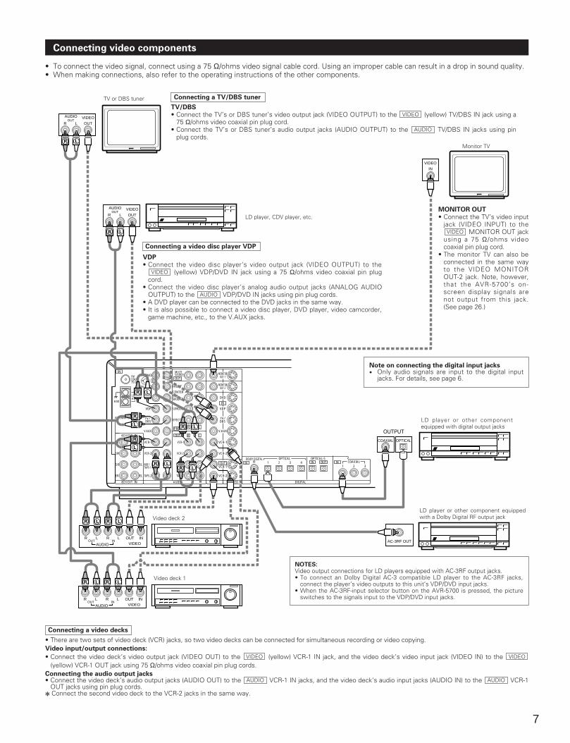
Connecting video components
• To connect the video signal, connect using a 75 Ω/ohms video signal cable cord. Using an improper cable can result in a drop in sound quality.• When making connections, also refer to the operating instructions of the other components.
Connecting a TV/DBS tuner
TV/DBS• Connect the TV’s or DBS tuner’s video output jack (VIDEO OUTPUT) to the (yellow) TV/DBS IN jack using a
75 Ω/ohms video coaxial pin plug cord.• Connect the TV’s or DBS tuner’s audio output jacks (AUDIO OUTPUT) to the TV/DBS IN jacks using pin
plug cords.AUDIO
VIDEO
TV or DBS tuner
LD player, CDV player, etc.
Video deck 1
Video deck 2
Monitor TV
MONITOR OUT• Connect the TV’s video input
jack (VIDEO INPUT) to theMONITOR OUT jack
using a 75 Ω/ohms videocoaxial pin plug cord.
• The monitor TV can also beconnected in the same wayto the VIDEO MONITOROUT-2 jack. Note, however,that the AVR-5700’s on-screen display signals arenot output from this jack.(See page 26.)
VIDEO
NOTES:Video output connections for LD players equipped with AC-3RF output jacks.• To connect an Dolby Digital AC-3 compatible LD player to the AC-3RF jacks,
connect the player’s video outputs to this unit’s VDP/DVD input jacks.• When the AC-3RF-input selector button on the AVR-5700 is pressed, the picture
switches to the signals input to the VDP/DVD input jacks.
Connecting a video disc player VDP
VDP• Connect the video disc player’s video output jack (VIDEO OUTPUT) to the
(yellow) VDP/DVD IN jack using a 75 Ω/ohms video coaxial pin plugcord.
• Connect the video disc player’s analog audio output jacks (ANALOG AUDIOOUTPUT) to the VDP/DVD IN jacks using pin plug cords.
• A DVD player can be connected to the DVD jacks in the same way.• It is also possible to connect a video disc player, DVD player, video camcorder,
game machine, etc., to the V.AUX jacks.
AUDIO
VIDEO
Connecting a video decks
• There are two sets of video deck (VCR) jacks, so two video decks can be connected for simultaneous recording or video copying.Video input/output connections:
• Connect the video deck’s video output jack (VIDEO OUT) to the (yellow) VCR-1 IN jack, and the video deck’s video input jack (VIDEO IN) to the (yellow) VCR-1 OUT jack using 75 Ω/ohms video coaxial pin plug cords.
Connecting the audio output jacks• Connect the video deck’s audio output jacks (AUDIO OUT) to the VCR-1 IN jacks, and the video deck’s audio input jacks (AUDIO IN) to the VCR-1
OUT jacks using pin plug cords.2 Connect the second video deck to the VCR-2 jacks in the same way.
AUDIOAUDIO
VIDEOVIDEO
Note on connecting the digital input jacks• Only audio signals are input to the digital input
jacks. For details, see page 6.
LD player or other componentequipped with digital output jacks
LD player or other component equippedwith a Dolby Digital RF output jack
8
OUT
OUT
OUT
PREOUT
PHONO
FRONT
CENTER
EFECT
SURROUND
SIGNALGND
CD
DVD
VDP
TV/ DBS
V.AUX
VCR-1
VCR-2
MD/ TAPE-1
TAPE-2
MONITORSOURCEMULTI
OUT-1
MONITOROUT-2
DVD
VDP
TV/DBS
V.AUX
VCR-1
VCR-2
VCR-1
VCR-2
VCR-1
VCR-2
MD/ TAPE-1
TAPE-2
6CH EXT. IN
FR
SW
SR
ER
FL
C
SL
EL
8CH EXT. IN AUDIO VIDEO S-VIDEO
SUBWOOFER
R L
R L
R L
IN
IN
LOOPANT.
AM
FMCOAX.75
ANTENNA TERMINALS
INS-VIDEO
OUTS-VIDEO
OUTS-VIDEO
OUT INS-VIDEO
OUT INS-VIDEO
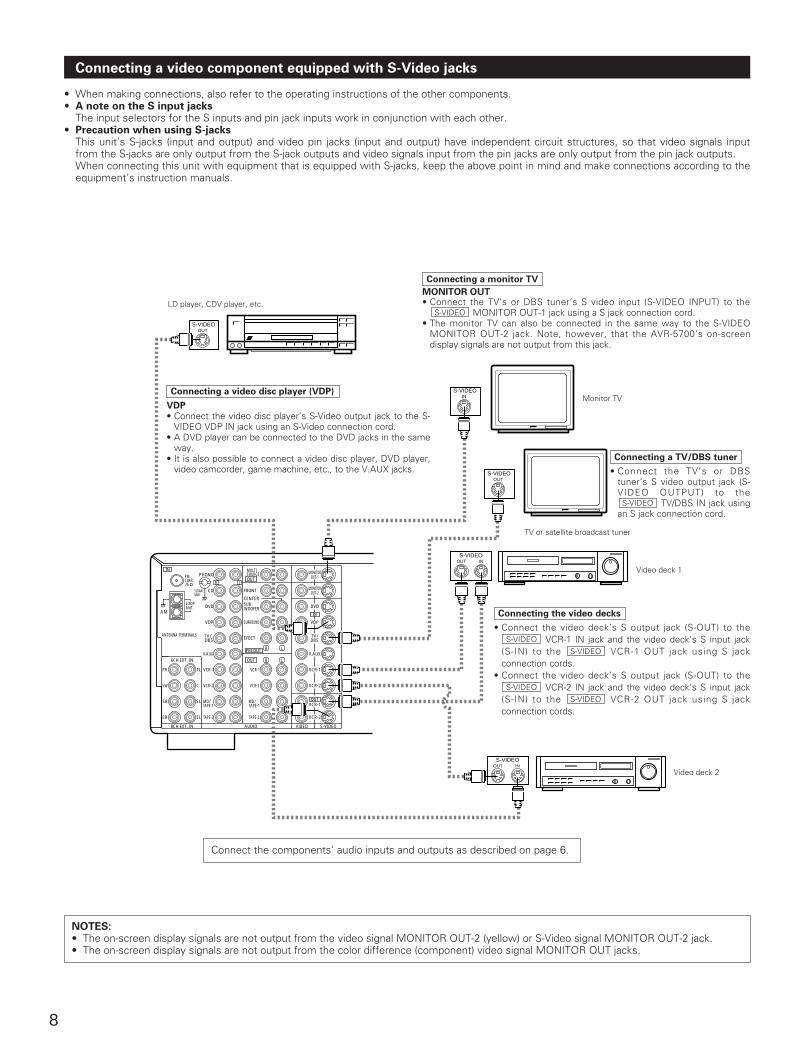
Connecting a video component equipped with S-Video jacks
• When making connections, also refer to the operating instructions of the other components.• A note on the S input jacks
The input selectors for the S inputs and pin jack inputs work in conjunction with each other.• Precaution when using S-jacks
This unit’s S-jacks (input and output) and video pin jacks (input and output) have independent circuit structures, so that video signals inputfrom the S-jacks are only output from the S-jack outputs and video signals input from the pin jacks are only output from the pin jack outputs. When connecting this unit with equipment that is equipped with S-jacks, keep the above point in mind and make connections according to theequipment’s instruction manuals.
LD player, CDV player, etc.MONITOR OUT• Connect the TV’s or DBS tuner’s S video input (S-VIDEO INPUT) to the
MONITOR OUT-1 jack using a S jack connection cord.• The monitor TV can also be connected in the same way to the S-VIDEO
MONITOR OUT-2 jack. Note, however, that the AVR-5700’s on-screendisplay signals are not output from this jack.
S-VIDEO
Connecting a TV/DBS tuner
• Connect the TV’s or DBStuner’s S video output jack (S-VIDEO OUTPUT) to the
TV/DBS IN jack usingan S jack connection cord.
S-VIDEO
Connecting the video decks
• Connect the video deck’s S output jack (S-OUT) to theVCR-1 IN jack and the video deck’s S input jack
(S-IN) to the VCR-1 OUT jack using S jackconnection cords.
• Connect the video deck’s S output jack (S-OUT) to theVCR-2 IN jack and the video deck’s S input jack
(S-IN) to the VCR-2 OUT jack using S jackconnection cords.
S-VIDEOS-VIDEO
S-VIDEOS-VIDEO
Connecting a video disc player (VDP)
VDP• Connect the video disc player’s S-Video output jack to the S-
VIDEO VDP IN jack using an S-Video connection cord.• A DVD player can be connected to the DVD jacks in the same
way.• It is also possible to connect a video disc player, DVD player,
video camcorder, game machine, etc., to the V.AUX jacks.
Monitor TV
TV or satellite broadcast tuner
Video deck 1
Video deck 2
Connect the components’ audio inputs and outputs as described on page 6.
NOTES:• The on-screen display signals are not output from the video signal MONITOR OUT-2 (yellow) or S-Video signal MONITOR OUT-2 jack.• The on-screen display signals are not output from the color difference (component) video signal MONITOR OUT jacks.
Connecting a monitor TV

9
OUT
OUT
OUT
PREOUT
PHONO
FRONT
CENTER
EFECT
SURROUND
SIGNALGND
CD
DVD
VDP
TV/ DBS
V.AUX
VCR-1
VCR-2
MD/ TAPE-1
TAPE-2
MONITORSOURCEMULTI
OUT-1
MONITOROUT-2
DVD
VDP
TV/DBS
V.AUX
VCR-1
VCR-2
VCR-1
VCR-2
VCR-1
VCR-2
MD/ TAPE-1
TAPE-2
6CH EXT. IN
FR
SW
SR
ER
FL
C
SL
EL
8CH EXT. IN AUDIO VIDEO S-VIDEO
SUBWOOFER
R L
R L
R L
IN
IN
LOOPANT.
AM
FMCOAX.75
ANTENNA TERMINALS
Note to CATV system installer:
This reminder is provided to call the CATV system installer’sattention to Article 820-40 of the NEC which providesguidelines for proper grounding and, in particular, specifiesthat the cable ground shall be connected to the groundingsystem of the building, as close to the point of cable entry aspractical.
Notes:
• Do not connect two FM antennas simultaneously.• Even if an external AM antenna is used, do not disconnect
the AM loop antenna.• Make sure AM loop antenna lead terminals do not touch
metal parts of the panel.
Connecting the antenna terminals
DIRECTION OF BROADCASTING STATION
FM ANTENNA
FEEDERCABLE
75 Ω/ohms COAXIAL CABLE
FM INDOORANTENNA(An Accessory)
AM LOOPANTENNA(An Accessory)
AM OUTDOORANTENNA
Connection of AM antennas
1. Loosen by turningcounterclockwise.
2. Insert the cord. 3. Tighten by turningclockwise.
1
4
23
14mm
9mm14mm
19mm
5mm
5mm
5C-2V3C-2V
5C-2V
300 Ω/ohms
300 Ω/ohmsTERMINALS
FM ANTENNAADAPTER(An Accessory)
AM loop antenna assembly
Remove the vinyl tieand take out theconnection line.
Connect to the AMantenna terminals.
Bend in the reversedirection.
Mount
Installation holeMount on wall, etc.
a. With the antennaon top any stablesurface.
b. With the antennaattached to a wall.
75 Ω/ohms COAXIAL CABLE
GROUND
Open the cover
ANTENNA ADAPTER
REMOVE
CLAMP
75 Ω/ohms COAXIAL CABLE
CLAMPCLAMP
SHUT
SHUT
PULL
PULL
• An F-type FM antenna cable plug can be connected directly.• If the FM antenna cable’s plug is not of the F-type, connect using the
included antenna adapter.
F-type converter plug (attached)• When using the FM antenna
attach to this apparatus
CLAMP
10
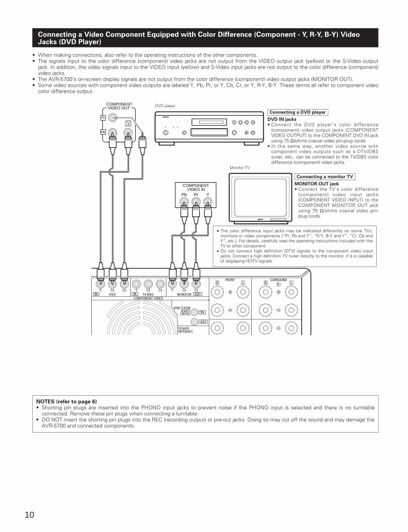
Connecting a Video Component Equipped with Color Difference (Component - Y, R-Y, B-Y) VideoJacks (DVD Player)
• When making connections, also refer to the operating instructions of the other components.• The signals input to the color difference (component) video jacks are not output from the VIDEO output jack (yellow) or the S-Video output
jack. In addition, the video signals input to the VIDEO input (yellow) and S-Video input jacks are not output to the color difference (component)video jacks.
• The AVR-5700’s on-screen display signals are not output from the color difference (component) video output jacks (MONITOR OUT).• Some video sources with component video outputs are labeled Y, Pb, Pr, or Y, Cb, Cr, or Y, R-Y, B-Y. These terms all refer to component video
color difference output.
OUT
OUT
6 16
R L
Y CBDVD TV/DBS
COMPONENT VIDEO
FRONTR L
SURROUND
SPEAKERIMPEDANCEFRONT CENTER /
MONITOR
ROOM TO ROOMREMOTE
CONTROL
CR Y CB CR Y CB CR
A
IN
IN IN
YPrPb
BB
VIDEO OUT
Pr
Y
Pb
COMPONENT
VIDEO INCOMPONENT
DVD player
Connecting a DVD player
DVD IN jacks• Connect the DVD player’s color difference
(component) video output jacks (COMPONENTVIDEO OUTPUT) to the COMPONENT DVD IN jackusing 75 Ω/ohms coaxial video pin-plug cords.
• In the same way, another video source withcomponent video outputs such as a DTV/DBStuner, etc., can be connected to the TV/DBS colordifference (component) video jacks.
Connecting a monitor TV
MONITOR OUT jack• Connect the TV’s color difference
(component) video input jacks(COMPONENT VIDEO INPUT) to theCOMPONENT MONITOR OUT jackusing 75 Ω/ohms coaxial video pin-plug cords.
Monitor TV
• The color difference input jacks may be indicated differently on some TVs,monitors or video components (“Pr, Pb and Y”, “R-Y, B-Y and Y”, “Cr, Cb andY”, etc.). For details, carefully read the operating instructions included with theTV or other component.
• Do not connect high definition (DTV) signals to the component video inputjacks. Connect a high definition TV tuner directly to the monitor, if it is capableof displaying HDTV signals.
NOTES (refer to page 6)• Shorting pin plugs are inserted into the PHONO input jacks to prevent noise if the PHONO input is selected and there is no turntable
connected. Remove these pin plugs when connecting a turntable.• DO NOT insert the shorting pin plugs into the REC (recording output) or pre-out jacks. Doing so may cut off the sound and may damage the
AVR-5700 and connected components.
11
OUT
OUT OUT
OUT
PREOUT
PHONO
FRONT
CENTER
EFECT
SURROUND
SIGNALGND
CD
DVD
VDP
TV/ DBS
V.AUX
VCR-1
VCR-2
MD/ TAPE-1
TAPE-2
MONITORSOURCEMULTI
OUT-1
MONITOROUT-2
DVD
VDP
TV/DBS
V.AUX
VCR-1
VCR-2
VCR-1
VCR-2
VCR-1
VCR-2
MD/ TAPE-1
TAPE-2
6CH EXT. IN
FR
SW
SR
ER
FL
C
SL
EL
8CH EXT. IN AUDIO VIDEO S-VIDEO DIGITAL
SUBWOOFER
R L
R L
R L Y CBDVD TV/DBS
COMPONENT VIDEO
OPTICALDOLBY DIGITALRF
OPTICAL-51 2 3 4
CR Y CB CR YIN IN
ININ
IN
IN
LOOPANT.
AM
FMCOAX.75
ANTENNA TERMINALS
L
R
L
R
R L
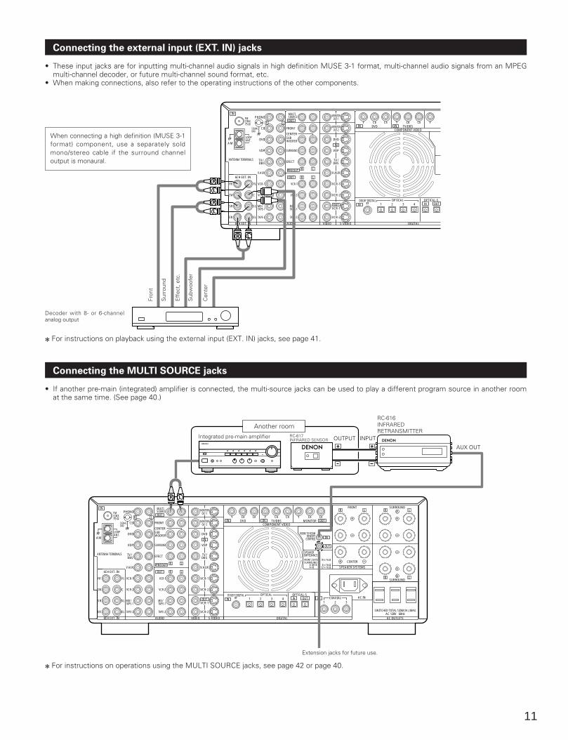
Connecting the external input (EXT. IN) jacks
• These input jacks are for inputting multi-channel audio signals in high definition MUSE 3-1 format, multi-channel audio signals from an MPEGmulti-channel decoder, or future multi-channel sound format, etc.
• When making connections, also refer to the operating instructions of the other components.
When connecting a high definition (MUSE 3-1format) component, use a separately soldmono/stereo cable if the surround channeloutput is monaural.
Decoder with 8- or 6-channelanalog output
Fron
t
Sur
roun
d
Eff
ect,
etc
.
Sub
woo
fer
Cen
ter
2 For instructions on playback using the external input (EXT. IN) jacks, see page 41.
Connecting the MULTI SOURCE jacks
• If another pre-main (integrated) amplifier is connected, the multi-source jacks can be used to play a different program source in another roomat the same time. (See page 40.)
++
OUTPUT INPUT
AUX OUT
A+B
OUT
OUT
OUT
OUT
OUT
OUT
PREOUT
6 16
PHONO
FRONT
CENTER
EFECT
SURROUND
SIGNALGND
CD
DVD
VDP
TV/ DBS
V.AUX
VCR-1
VCR-2
MD/ TAPE-1
TAPE-2
MONITORSOURCEMULTI
OUT-1
MONITOROUT-2
DVD
VDP
TV/DBS
V.AUX
VCR-1
VCR-2
VCR-1
VCR-2
VCR-1
VCR-2
MD/ TAPE-1
TAPE-2
6CH EXT. IN
FR
SW
SR
ER
FL
C
SL
EL
8CH EXT. IN AUDIO VIDEO S-VIDEO DIGITAL
SUBWOOFER
R L
R L
R L
R L Y CBDVD TV/DBS
COMPONENT VIDEO
SPEAKER SYSTEMS
OPTICALCOAXIAL
DOLBY DIGITALRF
OPTICAL-51 2 3
1 2 34
SWITCHED TOTAL 120W(1A.) MAX.AC 120V 60HzAC OUTLETS
AC IN
FRONT
CENTER
R L
R L
SURROUND
SURROUND
SPEAKERIMPEDANCEFRONT,CENTER /
6 1612 16
SURROUND /A OR B
MONITOR
ROOM TO ROOMREMOTE
CONTROL
CR Y CB CR Y CB CR
B
A
IN
IN IN
INININ
IN
IN
LOOPANT.
AM
FMCOAX.75
ANTENNA TERMINALS
LR
Another room
Integrated pre-main amplifier RC-617INFRARED SENSOR
RC-616INFRAREDRETRANSMITTER
2 For instructions on operations using the MULTI SOURCE jacks, see page 42 or page 40.
Extension jacks for future use.
12
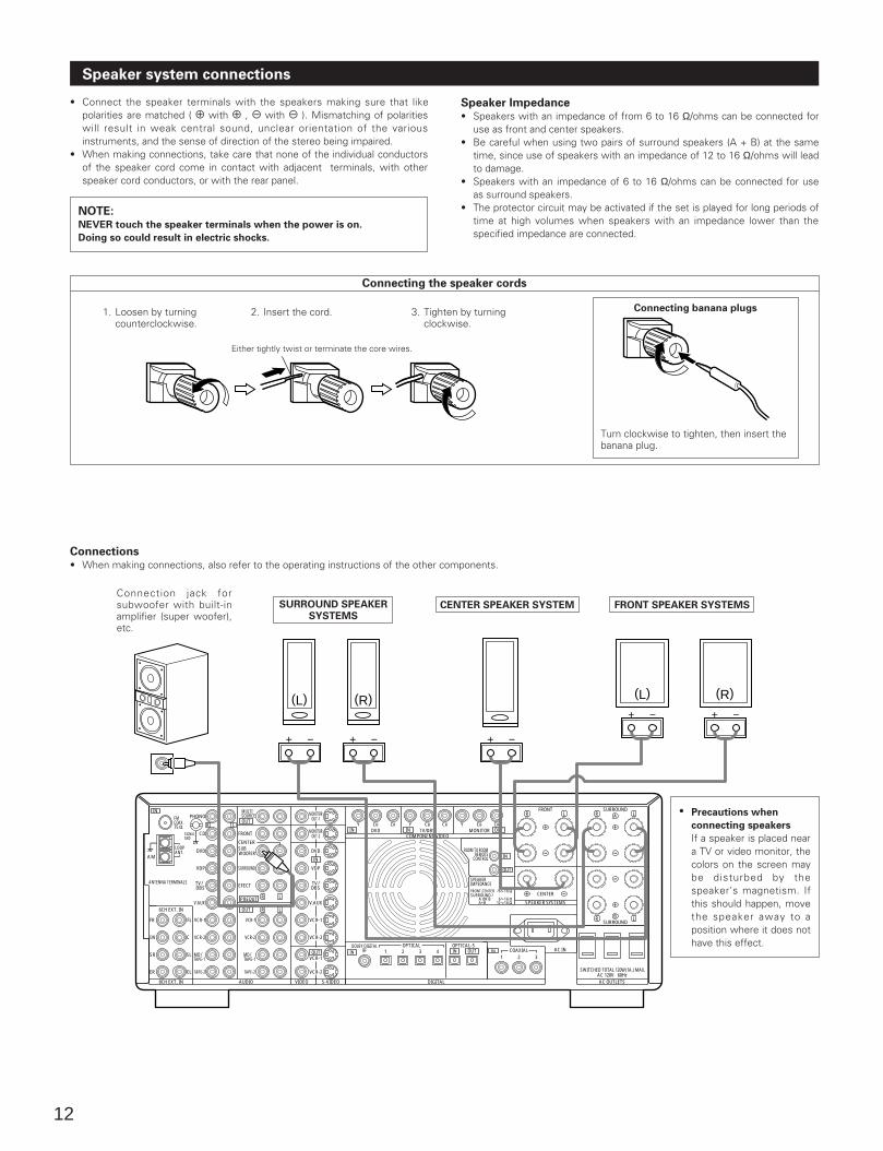
Speaker system connections
• Connect the speaker terminals with the speakers making sure that likepolarities are matched ( < with < , > with > ). Mismatching of polaritieswill result in weak central sound, unclear orientation of the variousinstruments, and the sense of direction of the stereo being impaired.
• When making connections, take care that none of the individual conductorsof the speaker cord come in contact with adjacent terminals, with otherspeaker cord conductors, or with the rear panel.
NOTE:NEVER touch the speaker terminals when the power is on.
Doing so could result in electric shocks.
Speaker Impedance• Speakers with an impedance of from 6 to 16 Ω/ohms can be connected for
use as front and center speakers.• Be careful when using two pairs of surround speakers (A + B) at the same
time, since use of speakers with an impedance of 12 to 16 Ω/ohms will leadto damage.
• Speakers with an impedance of 6 to 16 Ω/ohms can be connected for useas surround speakers.
• The protector circuit may be activated if the set is played for long periods oftime at high volumes when speakers with an impedance lower than thespecified impedance are connected.
A+B
OUT
OUT
OUT
OUT
OUT
OUT
PREOUT
6 16
PHONO
FRONT
CENTER
EFECT
SURROUND
SIGNALGND
CD
DVD
VDP
TV/ DBS
V.AUX
VCR-1
VCR-2
MD/ TAPE-1
TAPE-2
MONITORSOURCEMULTI
OUT-1
MONITOROUT-2
DVD
VDP
TV/DBS
V.AUX
VCR-1
VCR-2
VCR-1
VCR-2
VCR-1
VCR-2
MD/ TAPE-1
TAPE-2
6CH EXT. IN
FR
SW
SR
ER
FL
C
SL
EL
8CH EXT. IN AUDIO VIDEO S-VIDEO DIGITAL
SUBWOOFER
R L
R L
R L
R L Y CBDVD TV/DBS
COMPONENT VIDEO
SPEAKER SYSTEMS
OPTICALCOAXIAL
DOLBY DIGITALRF
OPTICAL-51 2 3
1 2 34
SWITCHED TOTAL 120W(1A.) MAX.AC 120V 60HzAC OUTLETS
AC IN
FRONT
CENTER
R L
R L
SURROUND
SURROUND
SPEAKERIMPEDANCEFRONT,CENTER /
6 1612 16
SURROUND /A OR B
MONITOR
ROOM TO ROOMREMOTE
CONTROL
CR Y CB CR Y CB CR
B
A
IN
IN IN
INININ
IN
IN
LOOPANT.
AM
FMCOAX.75
ANTENNA TERMINALS
(L) (R) (L) (R)
Connecting the speaker cords
1. Loosen by turning counterclockwise.
2. Insert the cord. 3. Tighten by turning clockwise.
Connecting banana plugs
Turn clockwise to tighten, then insert thebanana plug.
CENTER SPEAKER SYSTEM FRONT SPEAKER SYSTEMSSURROUND SPEAKERSYSTEMS
• Precautions when
connecting speakers
If a speaker is placed neara TV or video monitor, thecolors on the screen maybe disturbed by thespeaker’s magnetism. Ifthis should happen, movethe speaker away to aposition where it does nothave this effect.
Either tightly twist or terminate the core wires.
Connections• When making connections, also refer to the operating instructions of the other components.
Connection jack forsubwoofer with built-inamplifier (super woofer),etc.
13
Protector circuit
• This unit is equipped with a high-speed protection circuit. The purpose of this circuit is to protect the speakers undercircumstances such as when the output of the power amplifier is inadvertently short-circuited and a large current flows,when the temperature surrounding the unit becomes unusually high, or when the unit is used at high output over a longperiod which results in an extreme temperature rise. When the protection circuit is activated, the speaker output is cut off and the power supply indicator LED flashes.Should this occur, please follow these steps: be sure to switch off the power of this unit, check whether there are anyfaults with the wiring of the speaker cables or input cables, and wait for the unit to cool down if it is very hot. Improvethe ventilation condition around the unit and switch the power back on.If the protection circuit is activated again even though there are no problems with the wiring or the ventilation aroundthe unit, switch off the power and contact a DENON service center.
Note on speaker impedance
• The protector circuit may be activated if the set is played for long periods of time at high volumes when speakers withan impedance lower than the specified impedance (for example speakers with an impedance of lower than 4 Ω/ohms)are connected. If the protector circuit is activated, the speaker output is cut off. Turn off the set’s power, wait for the setto cool down, improve the ventilation around the set, then turn the power back on.
14
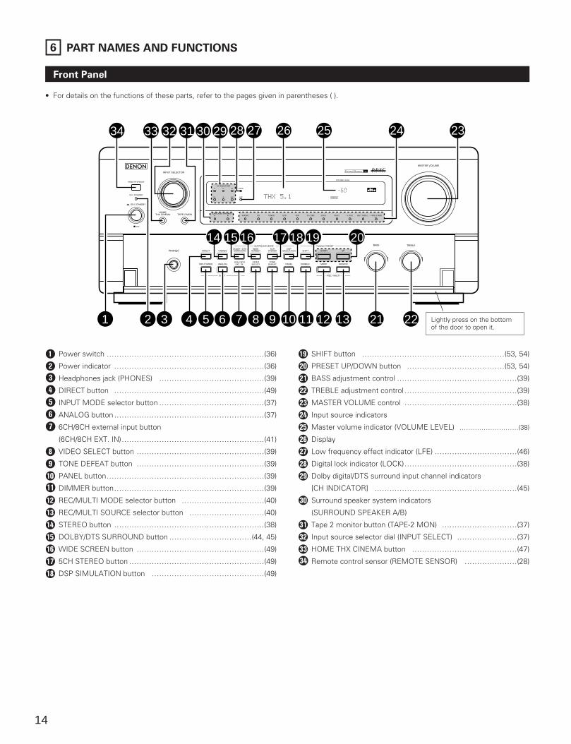
6 PART NAMES AND FUNCTIONS
Front Panel
• For details on the functions of these parts, refer to the pages given in parentheses ( ).
DSPSIMULATION
MASTER VOLUME
REMOTE SENSOR
ON / STANDBY
ON / STANDBY
OFF
INPUT SELECTOR
TAPE-2 MONHOME
THX CINEMA
VOLUME LEVEL
PHONES
BASS TREBLE
DIRECT
INPUT MODE
STEREO
ANALOG
DOLBY / DTSSURROUND
WIDESCREEN
5CHSTEREO
SURROUND MODE TUNING PRESET
SHIFT
6CH / 8CHEXT. IN
VIDEOSELECT
TONEDEFEAT DIMMERPANEL MODE SOURCE
INPUT REC / MULTI
DOWN UP
TUNER DVD VDP TV / DBS VCR-1 VCR-2 V. AUX MD / TAPE-1 TAPE-2 MONPHONO CD
L C R
SL S SR
CH INDICATORLOCK
LFE
SURROUND SPEAKERBA
14 15 16 17 18 19 20
1 2 3 4 5 6 7 8 9 10 11 12 13 21 22
34 33 32 31 30 29 28 27 26 25 24 23
Q Power switch ………………………………………………………(36)
W Power indicator ……………………………………………………(36)
E Headphones jack (PHONES) ……………………………………(39)
R DIRECT button ……………………………………………………(49)
T INPUT MODE selector button ……………………………………(37)
Y ANALOG button……………………………………………………(37)
U 6CH/8CH external input button
(6CH/8CH EXT. IN)…………………………………………………(41)
I VIDEO SELECT button ……………………………………………(39)
O TONE DEFEAT button ……………………………………………(39)
P PANEL button………………………………………………………(39)
DIMMER button……………………………………………………(39)
REC/MULTI MODE selector button ……………………………(40)
q REC/MULTI SOURCE selector button …………………………(40)
w STEREO button ……………………………………………………(38)
e DOLBY/DTS SURROUND button ……………………………(44, 45)
r WIDE SCREEN button ……………………………………………(49)
t 5CH STEREO button ………………………………………………(49)
y DSP SIMULATION button ………………………………………(49)
u SHIFT button …………………………………………………(53, 54)
i PRESET UP/DOWN button …………………………………(53, 54)
o BASS adjustment control …………………………………………(39)
p TREBLE adjustment control………………………………………(39)
[ MASTER VOLUME control ………………………………………(38)
] Input source indicators
A Master volume indicator (VOLUME LEVEL) ………………………(38)
S Display
D Low frequency effect indicator (LFE) ……………………………(46)
F Digital lock indicator (LOCK)………………………………………(38)
G Dolby digital/DTS surround input channel indicators
[CH INDICATOR] …………………………………………………(45)
H Surround speaker system indicators
(SURROUND SPEAKER A/B)
J Tape 2 monitor button (TAPE-2 MON) …………………………(37)
K Input source selector dial (INPUT SELECT) ……………………(37)
L HOME THX CINEMA button ……………………………………(47)
: Remote control sensor (REMOTE SENSOR) …………………(28)
Lightly press on the bottomof the door to open it.
15
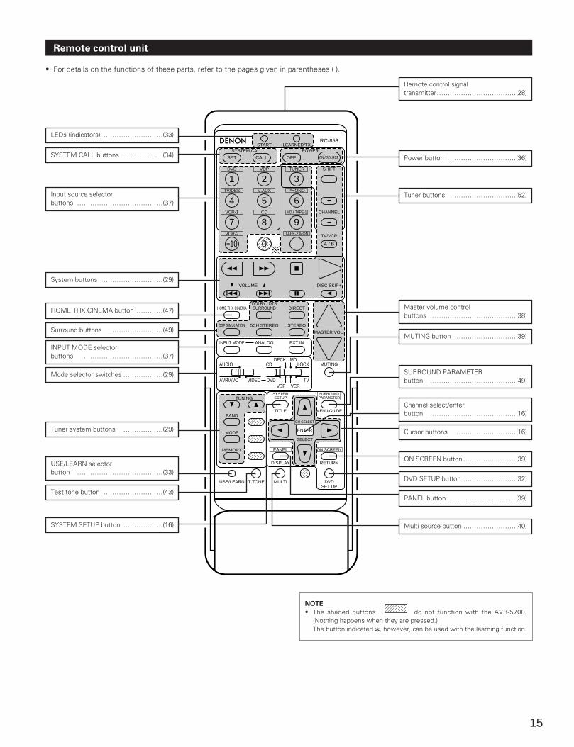
Remote control unit
• For details on the functions of these parts, refer to the pages given in parentheses ( ).
DVD
START LEARNED/TX
HOME THX CINEMA
TUNING
BANDTITLE MENU/GUIDE
MODE
MEMORY
USE/LEARN T.TONE MULTI DVDSET UP
RETURN
PANEL
DISPLAY
ON SCREEN
DOLBY / DTSSURROUND DIRECT
DSP SIMULATION 5CH STEREO STEREO
INPUT MODE ANALOG EXT.IN
MUTING
MASTER VOL.
VOLUME DISC SKIP+
SYSTEM CALL POWER
VDP TUNER SHIFT
TV/DBS V.AUX PHONO
VCR-1 CD MD / TAPE-1 CHANNEL
VCR-2 TAPE-2 MON TV/VCR
AVR/AVC VIDEO DVD TV
AUDIO
VDP VCR
CDMD
LOCKDECK
SYSTEMSETUP
SURROUNDPARAMETER
CH SELECT
SELECT
RC-853
1 2 3
4
SET
A / B
CALL OFF
ENTER
ON / SOURCE
5 6
7 8 9
+10 0
LEDs (indicators) ………………………(33)
SYSTEM CALL buttons ………………(34)
Input source selector buttons …………………………………(37)
System buttons ………………………(29)
HOME THX CINEMA button …………(47)
Surround buttons ……………………(49)
INPUT MODE selector buttons ………………………………(37)
Mode selector switches ………………(29)
Tuner system buttons ………………(29)
USE/LEARN selector button …………………………………(33)
Test tone button ………………………(43)
SYSTEM SETUP button ………………(16)
Remote control signal transmitter………………………………(28)
Power button …………………………(36)
Master volume control buttons …………………………………(38)
MUTING button ………………………(39)
SURROUND PARAMETER button …………………………………(49)
Channel select/enter button …………………………………(16)
Cursor buttons ………………………(16)
ON SCREEN button……………………(39)
DVD SETUP button ……………………(32)
PANEL button …………………………(39)
Multi source button ……………………(40)
NOTE
• The shaded buttons do not function with the AVR-5700.(Nothing happens when they are pressed.)The button indicated 2, however, can be used with the learning function.
Tuner buttons …………………………(52)
16
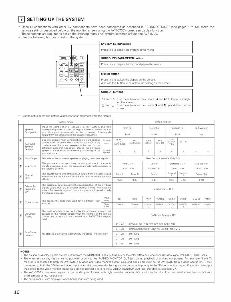
7 SETTING UP THE SYSTEM
• Once all connections with other AV components have been completed as described in “CONNECTIONS” (see pages 6 to 13), make thevarious settings described below on the monitor screen using the AVR-5700’s on-screen display function.These settings are required to set up the listening room’s AV system centered around the AVR-5700.
• Use the following buttons to set up the system:
TUNING
BANDTITLE MENU/GUIDE
MODE
MEMORY
USE/LEARN T.TONE MULTI
RETURN
DVDSET UP
PANEL
DISPLAY
ON SCREEN
MUTING
AVR/AVC VIDEO DVD TV
AUDIO
VDP VCR
CDMD
LOCKDECK
SYSTEMSETUP
SURROUNDPARAMETER
CH SELECT
SELECT
ENTER
SYSTEM SETUP button
Press this to display the system setup menu.
SURROUND PARAMETER button
Press this to display the surround parameter menu.
ENTER button
Press this to switch the display on the screen. Also use this button to complete the setting on the screen.
CURSOR buttons
and : Use these to move the cursors (0 and 1) to the left and righton the screen.
and : Use these to move the cursors (• and ª) up and down on thescreen.
• System setup items and default values (set upon shipment from the factory)
Default settings
Input the combination of speakers in your system and theircorresponding sizes (SMALL for regular speakers, LARGE for full-size, full-range) to automatically set the composition of the signalsoutput from the speakers and the frequency response.
Use this function when using multiple surround speakercombinations for more ideal surround sound. Once thecombinations of surround speakers to be used for thedifferent surround modes are preset, the surroundspeakers are selected automatically according to thesurround mode.
This selects the subwoofer speaker for playing deep bass signals.
This parameter is for optimizing the timing with which the audiosignals are produced from the speakers and subwoofer according tothe listening position.
This adjusts the volume of the signals output from the speakers andsubwoofer for the different channels in order to obtain optimumeffects.
This parameter is for detecting the maximum level of the low basssignals output from the subwoofer channel in order to protect thesubwoofer from damage and prevent unpleasant distorted soundsfrom being produced.
This assigns the digital input jacks for the different inputsources.
This sets whether or not to display the on-screen display thatappears on the monitor screen when the controls on the remotecontrol unit or main unit are operated (from MONITOR 1 outputsonly).
FM stations are received automatically and stored in the memory.
Front Sp.
Small
DOLBY/DTS
SURROUND
A
Center Sp.
Small
Surround Sp.
Small
Sub Woofer
Yes
System setup
SpeakerConfiguration
(SurroundSpeakerSetting)
Bass Output
Delay Time
ChannelLevel
SubwooferPeak LimitLev
Digital Inputs
On ScreenDisplay
Auto TunerPresets
Q
W
E
R
T
Y
U
I
Surroundmode
Surroundspeaker
THXSURROUND
A
WIDESCREEN
A
5CHSTEREO
A
DSPSIMULA-
TION
A
EXT. IN
A
—
—
—
—
Bass Out = Subwoofer Only THX
Front L & R
3.6 m (12 ft)
Center
3.6 m (12 ft)
Center
0 dB
Surround L & R
3.0 m (10 ft)
Sub Woofer
3.6 m (12 ft)
Subwoofer
0 dB
Front L
0 dB
Front R
0 dB
SurroundL
0 dB
SurroundR
0 dB
Peak Limitter = OFF
Inputsource
DigitalInputs
CD
COAXIAL1
DVD
COAXIAL2
VDP
COAXIAL3
TV/DBS
OPTICAL1
VCR-1
OPTICAL2
VCR-2
OPTICAL3
V. AUX
OPTICAL4
TAPE-1
OPTICAL5
On Screen Display = ON
A1 ~ A8
B1 ~B8
C1 ~C8
D1 ~D8
E1 ~E8
87.5/89.1/98.1/107.9/90.1/90.1/90.1/90.1 MHz
520/600/1000/1400/1500/1710 kHz/90.1/90.1 MHz
90.1 MHz
90.1 MHz
90.1 MHz
NOTES:
• The on-screen display signals are not output from the MONITOR OUT-2 output jack or the color difference (component) video signal (MONITOR OUT) jacks.• The on-screen display signals are output with priority to the S-VIDEO MONITOR OUT jack during playback of a video component. For example, if the TV
monitor is connected to both the AVR-5700’s S-Video and video monitor output jacks and signals are input to the AVR-5700 from a video source (VDP, etc.)connected to both the S-Video and video input jacks, the on-screen display signals are output with priority to the S-Video monitor output. If you wish to outputthe signals to the video monitor output jack, do not connect a cord to the S-VIDEO MONITOR OUT jack. (For details, see page 27.)
• The AVR-5700’s on-screen display function is designed for use with high resolution monitor TVs, so it may be difficult to read small characters on TVs withsmall screens or low resolutions.
• The setup menu is not displayed when headphones are being used.
17
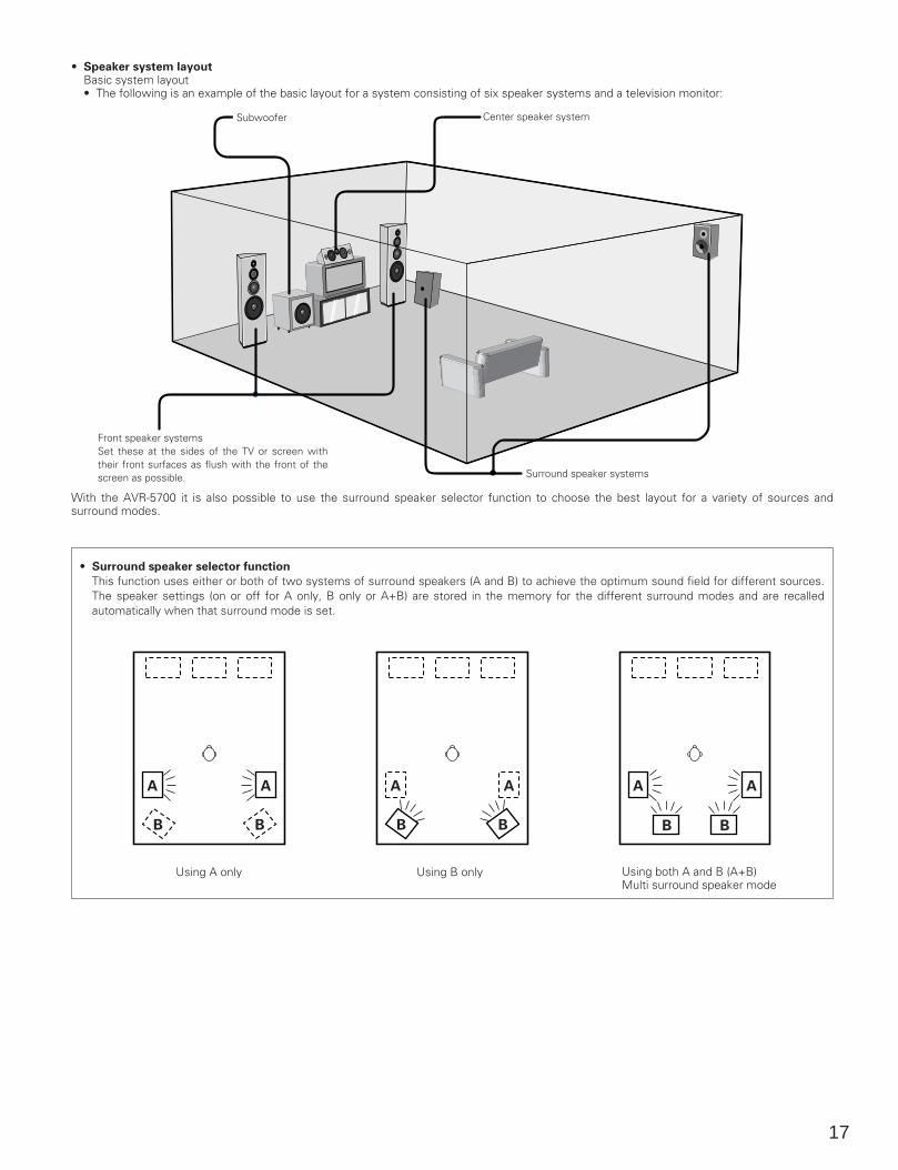
• Speaker system layoutBasic system layout• The following is an example of the basic layout for a system consisting of six speaker systems and a television monitor:
Subwoofer Center speaker system
Front speaker systemsSet these at the sides of the TV or screen withtheir front surfaces as flush with the front of thescreen as possible. Surround speaker systems
With the AVR-5700 it is also possible to use the surround speaker selector function to choose the best layout for a variety of sources andsurround modes.
• Surround speaker selector function
This function uses either or both of two systems of surround speakers (A and B) to achieve the optimum sound field for different sources.The speaker settings (on or off for A only, B only or A+B) are stored in the memory for the different surround modes and are recalledautomatically when that surround mode is set.
A A
BB
A A
BB
A A
BB
Using A only Using B only Using both A and B (A+B)Multi surround speaker mode

18
Before setting up the system
Check that all the connections are correct, then turn on the main unit’s power.12 Display the System Setup Menu.
TITLE
SYSTEMSETUP
Setting the type of speakers
• The composition of the signals output from the different channels and the frequency response are adjusted automatically according to thecombination of speakers actually being used.
1
2
3
At the System Setup Menu select “Speaker Configuration”.
Switch to the speaker configuration screen.
Set whether or not speakers are connected and, if so, their sizeparameters.• To select the speaker
• To select the parameter
ENTER
Center Sp.
Front Sp.
Subwoofer
Surround Sp.
19
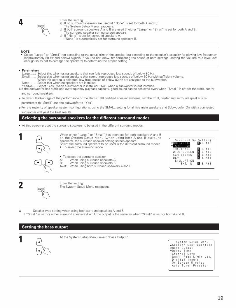
4 Enter the setting.a) If no surround speakers are used (if “None” is set for both A and B):
The System Setup Menu reappears.b) If both surround speakers A and B are used (if either “Large” or “Small” is set for both A and B):
The surround speaker setting screen appears.c) If “None” is set for surround speakers A:
“None” is automatically set for surround speakers B.
ENTER
NOTE:• Select “Large” or “Small” not according to the actual size of the speaker but according to the speaker’s capacity for playing low frequency
(approximately 80 Hz and below) signals. If you do not know, try comparing the sound at both settings (setting the volume to a level lowenough so as not to damage the speakers) to determine the proper setting.
• ParametersLarge…… Select this when using speakers that can fully reproduce low sounds of below 80 Hz. Small…… Select this when using speakers that cannot reproduce low sounds of below 80 Hz with sufficient volume.
When this setting is selected, low frequencies of below 80 Hz are assigned to the subwoofer.None…… Select this when no speakers are installed.Yes/No… Select “Yes” when a subwoofer is installed, “No” when a subwoofer is not installed.
2 If the subwoofer has sufficient low frequency playback capacity, good sound can be achieved even when “Small” is set for the front, centerand surround speakers.
2 To take full advantage of the performance of the Home THX certified speaker systems, set the front, center and surround speaker sizeparameters to “Small” and the subwoofer to “Yes”.
2 For the majority of speaker system configurations, using the SMALL setting for all five main speakers and Subwooofer On with a connectedsubwoofer will yield the best results.
Selecting the surround speakers for the different surround modes
• At this screen preset the surround speakers to be used in the different surround modes.
1
2
When either “Large” or “Small” has been set for both speakers A and Bon the System Setup Menu (when using both A and B surroundspeakers), the surround speaker setting screen appears.Select the surround speakers to be used in the different surround modes.• To select the surround mode
Enter the setting.The System Setup Menu reappears.
• To select the surround speakerA: When using surround speakers AB: When using surround speakers BA+B: When using both surround speakers A and B
ENTER
2 Speaker type setting when using both surround speakers A and BIf “Small” is set for either surround speakers A or B, the output is the same as when “Small” is set for both A and B.
Setting the bass output
1 At the System Setup Menu select “Bass Output”.
20
2
3
4
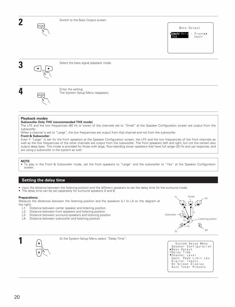
Switch to the Bass Output screen.
Select the bass signal playback mode.
Enter the setting.The System Setup Menu reappears.
ENTER
ENTER
Playback modesSubwoofer Only THX (recommended THX mode)The LFE and the low frequencies (80 Hz or lower) of the channels set to “Small” at the Speaker Configuration screen are output from thesubwoofer.When a channel is set to “Large”, the low frequencies are output from that channel and not from the subwoofer.Front & Subwoofer:Even if “Large” is set for the front speakers at the Speaker Configuration screen, the LFE and the low frequencies of the front channels aswell as the low frequencies of the other channels are output from the subwoofer. The front speakers (left and right, but not the center) alsooutput deep bass. This mode is provided for those with large, floor-standing tower speakers that have full range (20 Hz and up) response, andare using a subwoofer in the system as well.
NOTE:• To play in the Front & Subwoofer mode, set the front speakers to “Large” and the subwoofer to “Yes” at the Speaker Configuration
screen.
Setting the delay time
• Input the distance between the listening position and the different speakers to set the delay time for the surround mode.• The delay time can be set separately for surround speakers A and B.
Preparations:Measure the distances between the listening position and the speakers (L1 to L4 on the diagram atthe right).
L1: Distance between center speaker and listening positionL2: Distance between front speakers and listening positionL3: Distance between surround speakers and listening positionL4: Distance between subwoofer and listening position
L1L2
L3
L4
FLFR
SL SR
Center
Subwoofer
Listening position
1 At the System Setup Menu select “Delay Time”.
21
2
3
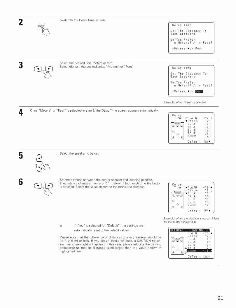
Switch to the Delay Time screen.
Select the desired unit, meters or feet.Select (darken) the desired units, “Meters” or “Feet”.
ENTER
Example: When “Feet” is selected
Once “Meters” or “Feet” is selected in step 3, the Delay Time screen appears automatically.4
5
6
Select the speaker to be set.
Set the distance between the center speaker and listening position.The distance changes in units of 0.1 meters (1 foot) each time the buttonis pressed. Select the value closest to the measured distance.
2 If “Yes” is selected for “Default”, the settings areautomatically reset to the default values.
Please note that the difference of distance for every speaker should be15 ft (4.5 m) or less. If you set an invalid distance, a CAUTION notice,such as screen right will appear. In this case, please relocate the blinkingspeaker(s) so that its distance is no larger than the value shown inhighlighted line.
Example: When the distance is set to 12 feetfor the center speaker (L1)
22
7 Enter the setting.The System Setup Menu reappears.The AVR-5700 automatically sets the optimum surround delay time for the listening room.
ENTER
NOTE:• If the distance unit is changed after the delay time is set, the settings are reset to the factory default values (see page 16).
Setting the channel level
• Use this setting to adjust so that the playback level between the different channels is equal.• From the listening position, listen to the test tones produced from the speakers to adjust the level.• The level can also be adjusted directly from the remote control unit. (For details, see page 43.)• When using both surround speakers A and B, their playback levels can be adjusted separately.
1
2
3
4
5
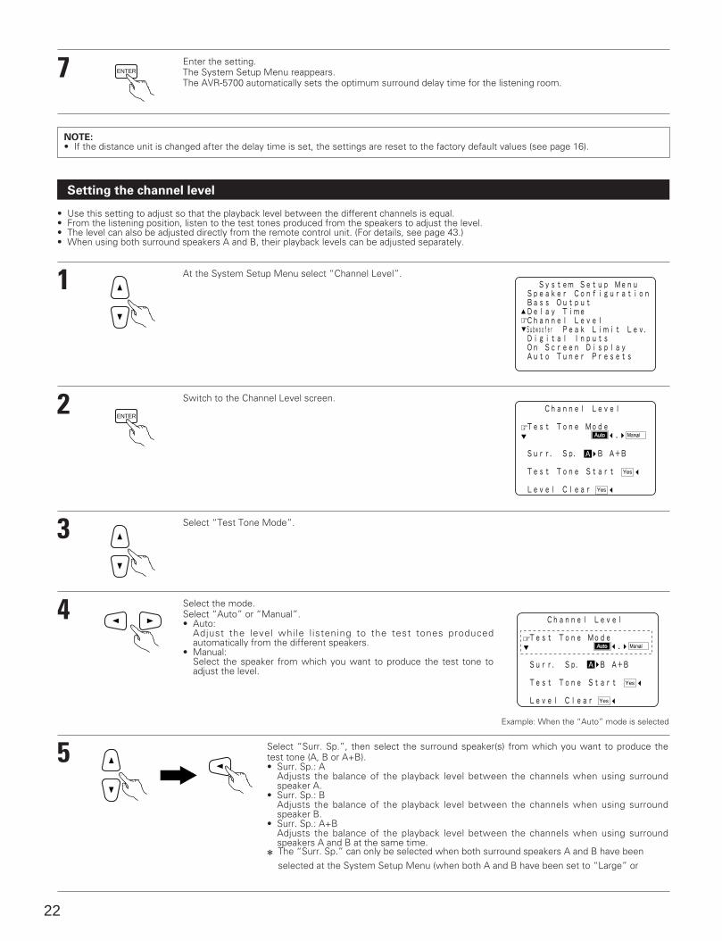
At the System Setup Menu select “Channel Level”.
Switch to the Channel Level screen.
Select “Test Tone Mode”.
Select the mode.Select “Auto” or “Manual”.• Auto:
Adjust the level while l istening to the test tones producedautomatically from the different speakers.
• Manual:Select the speaker from which you want to produce the test tone toadjust the level.
Select “Surr. Sp.”, then select the surround speaker(s) from which you want to produce thetest tone (A, B or A+B).• Surr. Sp.: A
Adjusts the balance of the playback level between the channels when using surroundspeaker A.
• Surr. Sp.: BAdjusts the balance of the playback level between the channels when using surroundspeaker B.
• Surr. Sp.: A+BAdjusts the balance of the playback level between the channels when using surroundspeakers A and B at the same time.
2 The “Surr. Sp.” can only be selected when both surround speakers A and B have beenselected at the System Setup Menu (when both A and B have been set to “Large” or
ENTER
Example: When the “Auto” mode is selected
23
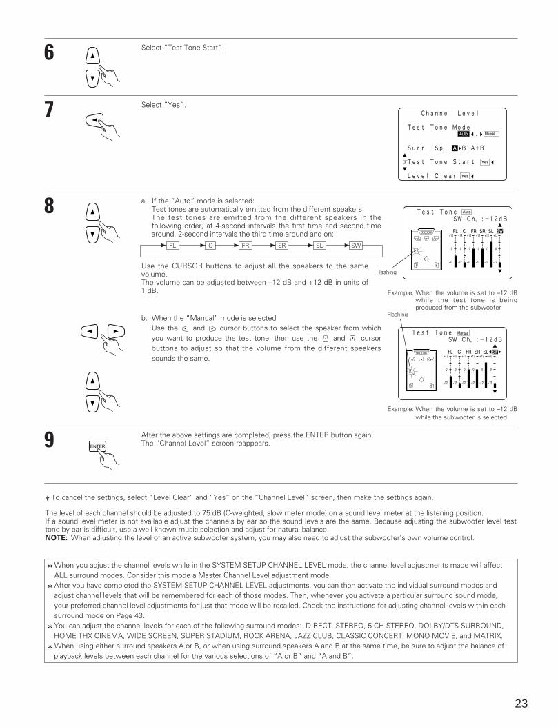
6 Select “Test Tone Start”.
7
8
Select “Yes”.
a. If the “Auto” mode is selected: Test tones are automatically emitted from the different speakers.The test tones are emitted from the different speakers in thefollowing order, at 4-second intervals the first time and second timearound, 2-second intervals the third time around and on:
FL C FR1 SR1 SL1 SW111
Use the CURSOR buttons to adjust all the speakers to the samevolume.The volume can be adjusted between –12 dB and +12 dB in units of1 dB. Example: When the volume is set to –12 dB
while the test tone is beingproduced from the subwoofer
Flashing
b. When the “Manual” mode is selected Use the and cursor buttons to select the speaker from whichyou want to produce the test tone, then use the and cursorbuttons to adjust so that the volume from the different speakerssounds the same.
Flashing
Example: When the volume is set to –12 dBwhile the subwoofer is selected
9 ENTER
After the above settings are completed, press the ENTER button again. The “Channel Level” screen reappears.
2 To cancel the settings, select “Level Clear” and “Yes” on the “Channel Level” screen, then make the settings again.
The level of each channel should be adjusted to 75 dB (C-weighted, slow meter mode) on a sound level meter at the listening position. If a sound level meter is not available adjust the channels by ear so the sound levels are the same. Because adjusting the subwoofer level testtone by ear is difficult, use a well known music selection and adjust for natural balance. NOTE: When adjusting the level of an active subwoofer system, you may also need to adjust the subwoofer’s own volume control.
2 When you adjust the channel levels while in the SYSTEM SETUP CHANNEL LEVEL mode, the channel level adjustments made will affectALL surround modes. Consider this mode a Master Channel Level adjustment mode.
2 After you have completed the SYSTEM SETUP CHANNEL LEVEL adjustments, you can then activate the individual surround modes andadjust channel levels that will be remembered for each of those modes. Then, whenever you activate a particular surround sound mode,your preferred channel level adjustments for just that mode will be recalled. Check the instructions for adjusting channel levels within eachsurround mode on Page 43.
2 You can adjust the channel levels for each of the following surround modes: DIRECT, STEREO, 5 CH STEREO, DOLBY/DTS SURROUND, HOME THX CINEMA, WIDE SCREEN, SUPER STADIUM, ROCK ARENA, JAZZ CLUB, CLASSIC CONCERT, MONO MOVIE, and MATRIX.
2 When using either surround speakers A or B, or when using surround speakers A and B at the same time, be sure to adjust the balance of playback levels between each channel for the various selections of “A or B” and “A and B”.
24
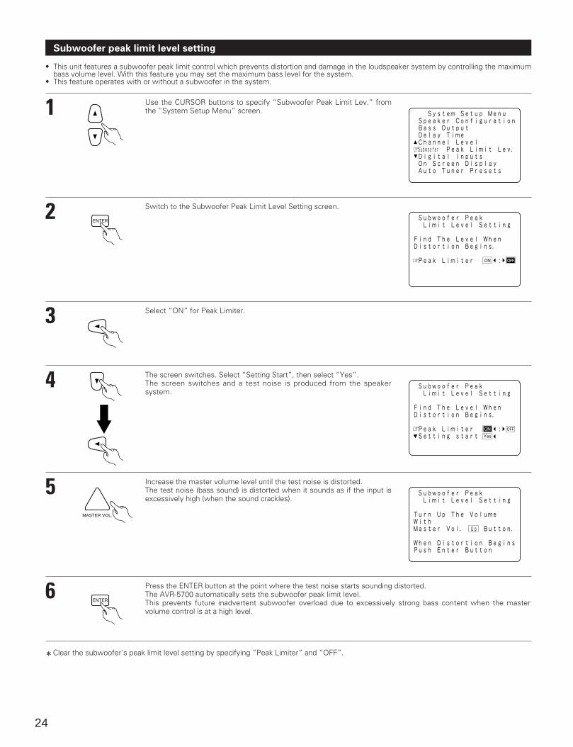
Subwoofer peak limit level setting
• This unit features a subwoofer peak limit control which prevents distortion and damage in the loudspeaker system by controlling the maximumbass volume level. With this feature you may set the maximum bass level for the system.
• This feature operates with or without a subwoofer in the system.
1
2
3
4
5
6
Use the CURSOR buttons to specify “Subwoofer Peak Limit Lev.” fromthe “System Setup Menu” screen.
Switch to the Subwoofer Peak Limit Level Setting screen.
Select “ON” for Peak Limiter.
The screen switches. Select “Setting Start”, then select “Yes”.The screen switches and a test noise is produced from the speakersystem.
Increase the master volume level until the test noise is distorted.The test noise (bass sound) is distorted when it sounds as if the input isexcessively high (when the sound crackles).
Press the ENTER button at the point where the test noise starts sounding distorted.The AVR-5700 automatically sets the subwoofer peak limit level.This prevents future inadvertent subwoofer overload due to excessively strong bass content when the mastervolume control is at a high level.
ENTER
MASTER VOL.
ENTER
2 Clear the subwoofer’s peak limit level setting by specifying “Peak Limiter” and “OFF”.

25
CAUTION!• The master volume is set to “–30 dB” when test tones are output.• The test tones are for confirming the low frequency playback limits and are played at an extremely high level. When using a low output
subwoofer, be very careful about irregular operations exceeding clipping by for example turning down the subwoofer’s attenuator beforestarting then slowly turning the attenuator up to the listening level.
• Also, when the subwoofer is set to “NO” in the speaker configuration, the test tones are output from the front speakers. When using frontspeakers with low input resistance, check that the sound is not clipped at sections where the signal is strong on the CD music sourcebefore starting the peak limit setting. The peak limit setting should not be performed if the music source cannot be played with the mastervolume set at “–15”. Set the front speakers to “small” and the subwoofer to “YES” in the speaker configuration. When this is done, thelow frequencies are cut, so the effect is insufficient. We strongly recommend adding a subwoofer.
• If the test tone is clipped when it is set to “–18 dB”, set the peak limit to “–18 dB”. In this case, the input resistance of the subwoofer orfront speakers is insufficient so clipping may occur when playing music. We recommend switching to a subwoofer with a higher inputresistance.
Setting the digital inputs
• This setting assigns the digital input jacks of the AVR-5700 for the different input sources.
1
2
3
4
At the System Setup Menu select “Digital Inputs”.
Switch to the Digital Inputs screen.
Select the digital input jack to be assigned to the input source.• To select the input source• To select the digital input jackSelect “OFF” for input sources for which no digital input jacks are used.2 If “Yes” is selected for “Default”, the settings are automatically reset to the default values.
Enter the setting.The System Setup Menu reappears.
ENTER
ENTER
NOTES:• The OPTICAL 5 jacks on the AVR-5700’s rear panel are equipped with an optical digital output jack for recording digital signals on a DAT
deck, MD player or other digital recorder. Use this for digital recording between a digital audio source (stereo - 2 channel) and a digital audiorecorder.
• Do not connect the output of the component connected to the OPTICAL 5 OUT jack on the AVR-5700’s rear panel to any jack other thanthe OPTICAL 5 IN jack.
• “PHONO”, “TAPE-2” and “TUNER” cannot be selected on the Digital Inputs screen.
26
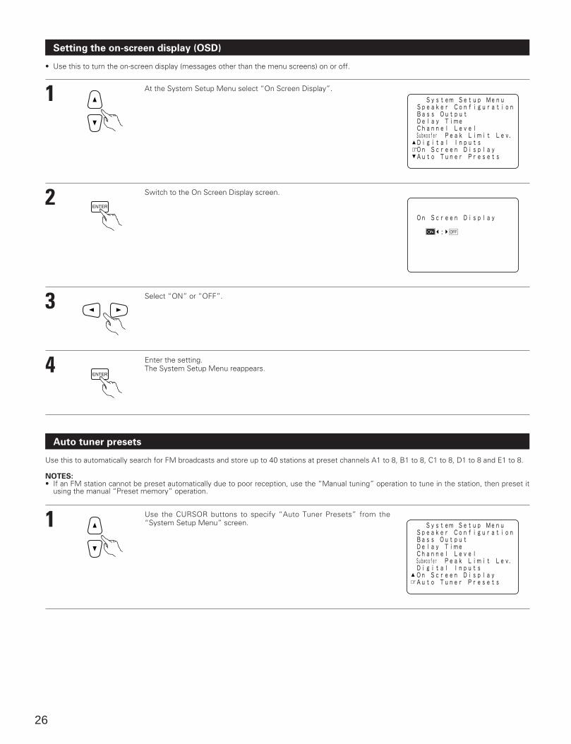
Setting the on-screen display (OSD)
• Use this to turn the on-screen display (messages other than the menu screens) on or off.
1
2
3
4
At the System Setup Menu select “On Screen Display”.
Switch to the On Screen Display screen.
Select “ON” or “OFF”.
Enter the setting.The System Setup Menu reappears.
ENTER
ENTER
Auto tuner presets
Use this to automatically search for FM broadcasts and store up to 40 stations at preset channels A1 to 8, B1 to 8, C1 to 8, D1 to 8 and E1 to 8.
NOTES:• If an FM station cannot be preset automatically due to poor reception, use the “Manual tuning” operation to tune in the station, then preset it
using the manual “Preset memory” operation.
1 Use the CURSOR buttons to specify “Auto Tuner Presets” from the“System Setup Menu” screen.
27
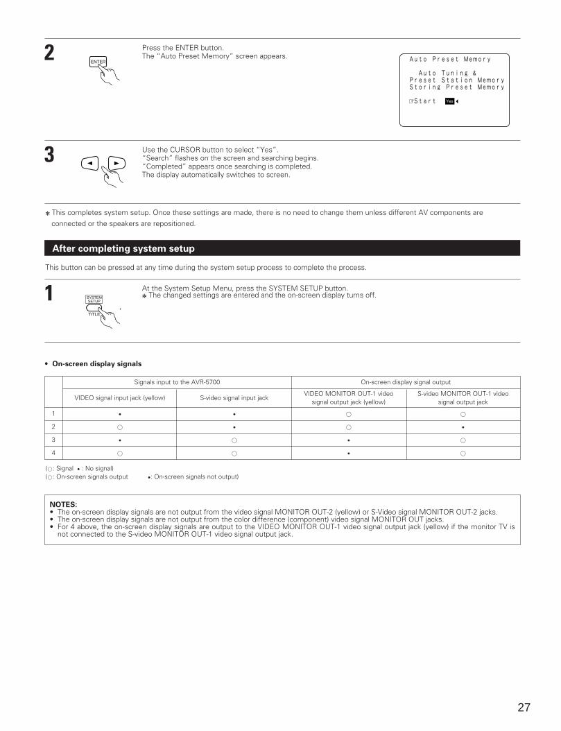
2
3
Press the ENTER button.The “Auto Preset Memory” screen appears.
Use the CURSOR button to select “Yes”.“Search” flashes on the screen and searching begins.“Completed” appears once searching is completed.The display automatically switches to screen.
ENTER
After completing system setup
1 At the System Setup Menu, press the SYSTEM SETUP button.2 The changed settings are entered and the on-screen display turns off.
TITLE
SYSTEMSETUP
This button can be pressed at any time during the system setup process to complete the process.
1
2
3
4
Signals input to the AVR-5700
VIDEO signal input jack (yellow)
E
A
E
A
S-video signal input jack
E
E
A
A
On-screen display signal output
(A: Signal E : No signal)(A: On-screen signals output E: On-screen signals not output)
• On-screen display signals
VIDEO MONITOR OUT-1 videosignal output jack (yellow)
A
A
E
E
S-video MONITOR OUT-1 videosignal output jack
A
E
A
A
NOTES:• The on-screen display signals are not output from the video signal MONITOR OUT-2 (yellow) or S-Video signal MONITOR OUT-2 jacks.• The on-screen display signals are not output from the color difference (component) video signal MONITOR OUT jacks.• For 4 above, the on-screen display signals are output to the VIDEO MONITOR OUT-1 video signal output jack (yellow) if the monitor TV is
not connected to the S-video MONITOR OUT-1 video signal output jack.
2 This completes system setup. Once these settings are made, there is no need to change them unless different AV components are connected or the speakers are repositioned.
28
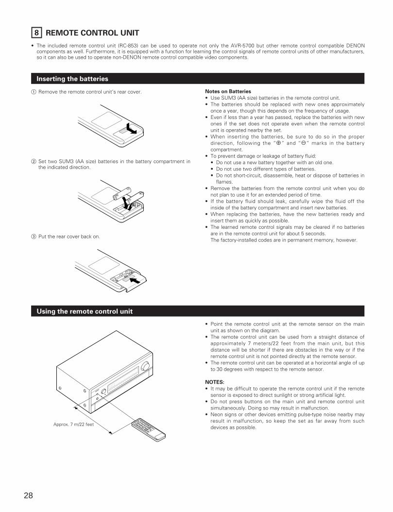
8 REMOTE CONTROL UNIT
• The included remote control unit (RC-853) can be used to operate not only the AVR-5700 but other remote control compatible DENONcomponents as well. Furthermore, it is equipped with a function for learning the control signals of remote control units of other manufacturers,so it can also be used to operate non-DENON remote control compatible video components.
Inserting the batteries
1 Remove the remote control unit’s rear cover.
2 Set two SUM3 (AA size) batteries in the battery compartment inthe indicated direction.
3 Put the rear cover back on.
Notes on Batteries
• Use SUM3 (AA size) batteries in the remote control unit.• The batteries should be replaced with new ones approximately
once a year, though this depends on the frequency of usage.• Even if less than a year has passed, replace the batteries with new
ones if the set does not operate even when the remote controlunit is operated nearby the set.
• When inserting the batteries, be sure to do so in the properdirection, following the “<” and “>” marks in the batterycompartment.
• To prevent damage or leakage of battery fluid:• Do not use a new battery together with an old one.• Do not use two different types of batteries.• Do not short-circuit, disassemble, heat or dispose of batteries in
flames.• Remove the batteries from the remote control unit when you do
not plan to use it for an extended period of time.• If the battery fluid should leak, carefully wipe the fluid off the
inside of the battery compartment and insert new batteries.• When replacing the batteries, have the new batteries ready and
insert them as quickly as possible.• The learned remote control signals may be cleared if no batteries
are in the remote control unit for about 5 seconds.The factory-installed codes are in permanent memory, however.
Using the remote control unit
Approx. 7 m/22 feet
• Point the remote control unit at the remote sensor on the mainunit as shown on the diagram.
• The remote control unit can be used from a straight distance ofapproximately 7 meters/22 feet from the main unit, but thisdistance will be shorter if there are obstacles in the way or if theremote control unit is not pointed directly at the remote sensor.
• The remote control unit can be operated at a horizontal angle of upto 30 degrees with respect to the remote sensor.
NOTES:
• It may be difficult to operate the remote control unit if the remotesensor is exposed to direct sunlight or strong artificial light.
• Do not press buttons on the main unit and remote control unitsimultaneously. Doing so may result in malfunction.
• Neon signs or other devices emitting pulse-type noise nearby mayresult in malfunction, so keep the set as far away from suchdevices as possible.
29
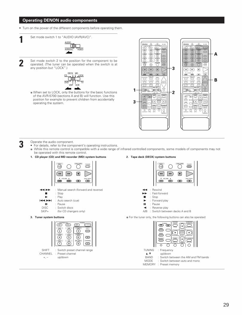
Operating DENON audio components
• Turn on the power of the different components before operating them.
1
2
Set mode switch 1 to “AUDIO (AVR/AVC)”.
Set mode switch 2 to the position for the component to beoperated. (The tuner can be operated when the switch is atany position but “LOCK”.)
2 When set to LOCK, only the buttons for the basic functions of the AVR-5700 (sections A and B) will function. Use this position for example to prevent children from accidentally operating the system.
AVR/AVC VIDEO
AUDIO
DVD TVVDP VCR
CDMD
LOCKDECK
DVD
START LEARNED/TX
HOME THX CINEMA
TUNING
BANDTITLE MENU/GUIDE
MODE
MEMORY
USE/LEARN T.TONE MULTI DVDSET UP
RETURN
PANEL
DISPLAY
ON SCREEN
DOLBY / DTSSURROUND DIRECT
DSP SIMULATION 5CH STEREO STEREO
INPUT MODE ANALOG EXT.IN
MUTING
MASTER VOL.
VOLUME DISC SKIP+
SYSTEM CALL POWER
VDP TUNER SHIFT
TV/DBS V.AUX PHONO
VCR-1 CD MD / TAPE-1 CHANNEL
VCR-2 TAPE-2 MON TV/VCR
AVR/AVC VIDEO DVD TV
AUDIO
VDP VCR
CDMD
LOCKDECK
SYSTEMSETUP
SURROUNDPARAMETER
CH SELECT
SELECT
RC-853
1 2 3
4
SET
A / B
CALL OFF
ENTER
ON / SOURCE
5 6
7 8 9
+10
DVD
START LEARNED/TX
HOME THX CINEMA
TUNING
BANDTITLE MENU/GUIDE
MODE
MEMORY
USE/LEARN T.TONE MULTI DVDSET UP
RETURN
PANEL
DISPLAY
ON SCREEN
DOLBY / DTSSURROUND DIRECT
DSP SIMULATION 5CH STEREO STEREO
INPUT MODE ANALOG EXT.IN
MUTING
MASTER VOL.
VOLUME DISC SKIP+
SYSTEM CALL POWER
VDP TUNER SHIFT
TV/DBS V.AUX PHONO
VCR-1 CD MD / TAPE-1 CHANNEL
VCR-2 TAPE-2 MON TV/VCR
AVR/AVC VIDEO DVD TV
AUDIO
VDP VCR
CDMD
LOCKDECK
SYSTEMSETUP
SURROUNDPARAMETER
CH SELECT
SELECT
RC-853
1 2 3
4
SET
A / B
CALL OFF
ENTER
ON / SOURCE
5 6
7 8 9
+100 0
3
A
B
21
3
3 Operate the audio component.• For details, refer to the component’s operating instructions.2 While this remote control is compatible with a wide range of infrared controlled components, some models of components may not
be operated with this remote control.
VOLUME DISC SKIP+
VCR-2 TAPE-2 MON TV/VCR
A / B+10
VOLUME DISC SKIP+
VCR-2 TAPE-2 MON TV/VCR
A / B+10
1. CD player (CD) and MD recorder (MD) system buttons 2. Tape deck (DECK) system buttons
6,7 : Manual search (forward and reverse)2 : Stop1 : Play
8,9 : Auto search (cue)3 : Pause
DISC : Switch discsSKIP+ (for CD changers only)
6 : Rewind7 : Fast-forward2 : Stop1 : Forward play3 : Pause0 : Reverse playA/B : Switch between decks A and B
DVD
SYSTEM CALL POWER
VDP TUNER SHIFT
TV/DBS V.AUX PHONO
VCR-1 CD MD / TAPE-1 CHANNEL
1 2 3
4
SET CALL OFF ON / SOURCE
5 6
7 8 9
3. Tuner system buttons
SHIFT : Switch preset channel rangeCHANNEL : Preset channel
+, – up/down
TUNING
BANDTITLE MENU/GUIDE
MODE
MEMORY
RETURN
PANEL
DISPLAY
ON SCREEN
SYSTEMSETUP
SURROUNDPARAMETER
CH SELECT
SELECT
ENTER
2 For the tuner only, the following buttons can also be operated:
TUNING : Frequency •, ª up/down
BAND : Switch between the AM and FM bandsMODE : Switch between auto and mono
MEMORY : Preset memory
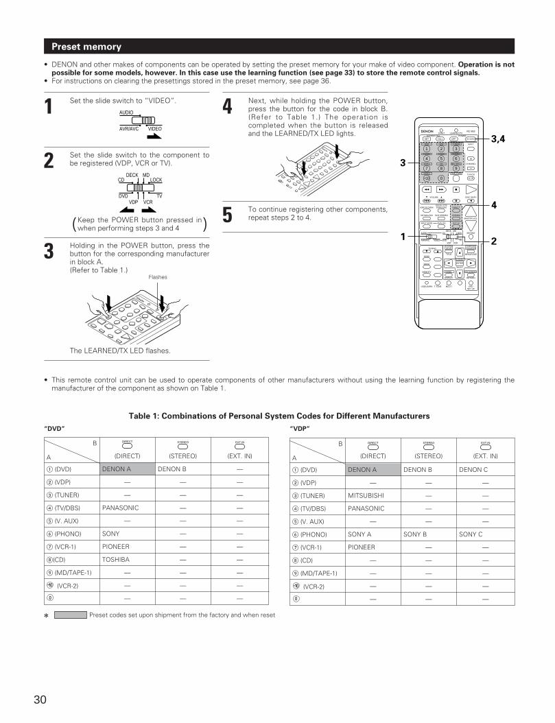
DENON A
30
Preset memory
• DENON and other makes of components can be operated by setting the preset memory for your make of video component. Operation is notpossible for some models, however. In this case use the learning function (see page 33) to store the remote control signals.
• For instructions on clearing the presettings stored in the preset memory, see page 36.
1
2
Set the slide switch to “VIDEO”.
Set the slide switch to the component tobe registered (VDP, VCR or TV).
AVR/AVC VIDEO
AUDIO
DVD TVVDP VCR
CDMD
LOCKDECK
Keep the POWER button pressed inwhen performing steps 3 and 4 )(
3 Holding in the POWER button, press thebutton for the corresponding manufacturerin block A.(Refer to Table 1.)
Flashes
The LEARNED/TX LED flashes.
4 Next, while holding the POWER button,press the button for the code in block B.(Refer to Table 1.) The operation iscompleted when the button is releasedand the LEARNED/TX LED lights.
5 To continue registering other components,repeat steps 2 to 4.
DVD
START LEARNED/TX
HOME THX CINEMA
TUNING
BANDTITLE MENU/GUIDE
MODE
MEMORY
USE/LEARN T.TONE MULTI DVDSET UP
RETURN
PANEL
DISPLAY
ON SCREEN
DOLBY / DTSSURROUND DIRECT
DSP SIMULATION 5CH STEREO STEREO
INPUT MODE ANALOG EXT.IN
MUTING
MASTER VOL.
VOLUME DISC SKIP+
SYSTEM CALL POWER
VDP TUNER SHIFT
TV/DBS V.AUX PHONO
VCR-1 CD MD / TAPE-1 CHANNEL
VCR-2 TAPE-2 MON TV/VCR
AVR/AVC VIDEO DVD TV
AUDIO
VDP VCR
CDMD
LOCKDECK
SYSTEMSETUP
SURROUNDPARAMETER
CH SELECT
SELECT
RC-853
1 2 3
4
SET
A / B
CALL OFF
ENTER
ON / SOURCE
5 6
7 8 9
+10 0
3
3,4
4
21
Table 1: Combinations of Personal System Codes for Different Manufacturers
“DVD” “VDP”
A
1 (DVD)
2 (VDP)
3 (TUNER)
4 (TV/DBS)
5 (V. AUX)
6 (PHONO)
7 (VCR-1)
8(CD)
9 (MD/TAPE-1)
—
—
PANASONIC
—
SONY
PIONEER
TOSHIBA
—
—
—
DENON B
—
—
—
—
—
—
—
—
—
—
—
—
—
—
—
—
—
—
—
—
—
B DIRECT STEREO EXT.IN
2 Preset codes set upon shipment from the factory and when reset
A
1 (DVD)
2 (VDP)
3 (TUNER)
4 (TV/DBS)
5 (V. AUX)
6 (PHONO)
7 (VCR-1)
8 (CD)
9 (MD/TAPE-1)
DENON A
—
MITSUBISHI
PANASONIC
—
SONY A
PIONEER
—
—
—
—
DENON B
—
—
—
—
SONY B
—
—
—
—
—
DENON C
—
—
—
—
SONY C
—
—
—
—
—
B DIRECT STEREO EXT.IN
(DIRECT) (STEREO) (EXT. IN) (DIRECT) (STEREO) (EXT. IN)
(VCR-2) (VCR-2)
• This remote control unit can be used to operate components of other manufacturers without using the learning function by registering themanufacturer of the component as shown on Table 1.
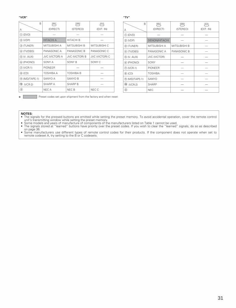
31
“VCR” “TV”
A
1 (DVD)
2 (VDP)
3 (TUNER)
4 (TV/DBS)
5 (V. AUX)
6 (PHONO)
7 (VCR-1)
8 (CD)
9 (MD/TAPE-1)
—
HITACHI A
MITSUBISHI A
PANASONIC A
JVC (VICTOR) A
SONY A
PIONEER
TOSHIBA A
SANYO A
SHARP A
NEC A
—
HITACHI B
MITSUBISHI B
PANASONIC B
JVC (VICTOR) B
SONY B
—
TOSHIBA B
SANYO B
SHARP B
NEC B
—
—
MITSUBISHI C
PANASONIC C
JVC (VICTOR) C
SONY C
—
—
—
—
NEC C
B DIRECT STEREO EXT.IN
2 Preset codes set upon shipment from the factory and when reset
A
1 (DVD)
2 (VDP)
3 (TUNER)
4 (TV/DBS)
5 (V. AUX)
6 (PHONO)
7 (VCR-1)
8 (CD)
9 (MD/TAPE-1)
—
DENON/HITACHI
MITSUBISHI A
PANASONIC A
JVC (VICTOR)
SONY
PIONEER
TOSHIBA
SANYO
SHARP
NEC
—
—
MITSUBISHI B
PANASONIC B
—
—
—
—
—
—
—
—
—
—
—
—
—
—
—
—
—
—
B DIRECT STEREO EXT.IN
NOTES:• The signals for the pressed buttons are emitted while setting the preset memory. To avoid accidental operation, cover the remote control
unit’s transmitting window while setting the preset memory.• Some models and years of manufacture of components of the manufacturers listed on Table 1 cannot be used.• The signals stored at “learned” buttons have priority over the preset codes. If you wish to clear the “learned” signals, do so as described
on page 36.• Some manufacturers use different types of remote control codes for their products. If the component does not operate when set to
remote codeset A, try setting to the B or C codesets.
(DIRECT) (STEREO) (EXT. IN) (DIRECT) (STEREO) (EXT. IN)
(VCR-2) (VCR-2)
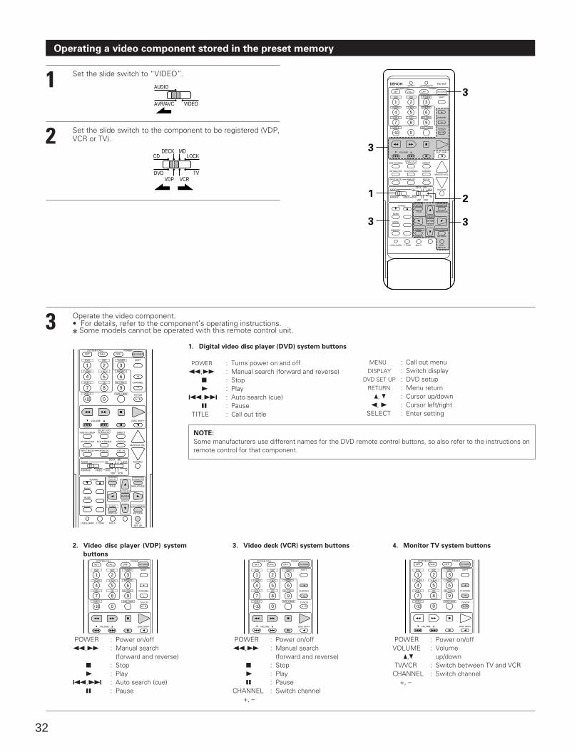
32
3 Operate the video component.• For details, refer to the component’s operating instructions.2 Some models cannot be operated with this remote control unit.
DVD
HOME THX CINEMA
TUNING
BANDTITLE MENU/GUIDE
MODE
MEMORY
USE/LEARN T.TONE MULTI DVDSET UP
RETURN
PANEL
DISPLAY
ON SCREEN
DOLBY / DTSSURROUND DIRECT
DSP SIMULATION 5CH STEREO STEREO
INPUT MODE ANALOG EXT.IN
MUTING
MASTER VOL.
VOLUME DISC SKIP+
SYSTEM CALL POWER
VDP TUNER SHIFT
TV/DBS V.AUX PHONO
VCR-1 CD MD / TAPE-1 CHANNEL
VCR-2 TAPE-2 MON TV/VCR
AVR/AVC VIDEO DVD TV
AUDIO
VDP VCR
CDMD
LOCKDECK
SYSTEMSETUP
SURROUNDPARAMETER
CH SELECT
SELECT
1 2 3
4
SET
A / B
CALL OFF
ENTER
ON / SOURCE
5 6
7 8 9
+10 0
1. Digital video disc player (DVD) system buttons
POWER : Turns power on and off6,7 : Manual search (forward and reverse)
2 : Stop1 : Play
8,9 : Auto search (cue)3 : Pause
TITLE : Call out title
MENU : Call out menuDISPLAY : Switch display
DVD SET UP : DVD setupRETURN : Menu return
•, ª : Cursor up/down0, 1 : Cursor left/right
SELECT : Enter setting
NOTE:
Some manufacturers use different names for the DVD remote control buttons, so also refer to the instructions onremote control for that component.
2. Video disc player (VDP) system
buttons
3. Video deck (VCR) system buttons 4. Monitor TV system buttons
DVD
VOLUME DISC SKIP+
SYSTEM CALL POWER
VDP TUNER SHIFT
TV/DBS V.AUX PHONO
VCR-1 CD MD / TAPE-1 CHANNEL
VCR-2 TAPE-2 MON TV/VCR
1 2 3
4
SET
A / B
CALL OFF ON / SOURCE
5 6
7 8 9
+10 0
DVD
VOLUME DISC SKIP+
SYSTEM CALL POWER
VDP TUNER SHIFT
TV/DBS V.AUX PHONO
VCR-1 CD MD / TAPE-1 CHANNEL
VCR-2 TAPE-2 MON TV/VCR
1 2 3
4
SET
A / B
CALL OFF ON / SOURCE
5 6
7 8 9
+10 0
DVD
VOLUME DISC SKIP+
SYSTEM CALL POWER
VDP TUNER SHIFT
TV/DBS V.AUX PHONO
VCR-1 CD MD / TAPE-1 CHANNEL
VCR-2 TAPE-2 MON TV/VCR
1 2 3
4
SET
A / B
CALL OFF ON / SOURCE
5 6
7 8 9
+10 0
POWER : Power on/off6,7 : Manual search
(forward and reverse)2 : Stop1 : Play
8,9 : Auto search (cue)3 : Pause
POWER : Power on/off6,7 : Manual search
(forward and reverse)2 : Stop1 : Play3 : Pause
CHANNEL : Switch channel+, –
POWER : Power on/offVOLUME : Volume
•,ª up/downTV/VCR : Switch between TV and VCRCHANNEL : Switch channel
+, –
Operating a video component stored in the preset memory
1
2
Set the slide switch to “VIDEO”.
Set the slide switch to the component to be registered (VDP,VCR or TV).
AVR/AVC VIDEO
AUDIO
DVD TVVDP VCR
CDMD
LOCKDECK
DVD
START LEARNED/TX
HOME THX CINEMA
TUNING
BANDTITLE MENU/GUIDE
MODE
MEMORY
USE/LEARN T.TONE MULTI DVDSET UP
RETURN
PANEL
DISPLAY
ON SCREEN
DOLBY / DTSSURROUND DIRECT
DSP SIMULATION 5CH STEREO STEREO
INPUT MODE ANALOG EXT.IN
MUTING
MASTER VOL.
VOLUME DISC SKIP+
SYSTEM CALL POWER
VDP TUNER SHIFT
TV/DBS V.AUX PHONO
VCR-1 CD MD / TAPE-1 CHANNEL
VCR-2 TAPE-2 MON TV/VCR
AVR/AVC VIDEO DVD TV
AUDIO
VDP VCR
CDMD
LOCKDECK
SYSTEMSETUP
SURROUNDPARAMETER
CH SELECT
SELECT
RC-853
1 2 3
4
SET
A / B
CALL OFF
ENTER
ON / SOURCE
5 6
7 8 9
+10 0
3
3
2
3
1
3
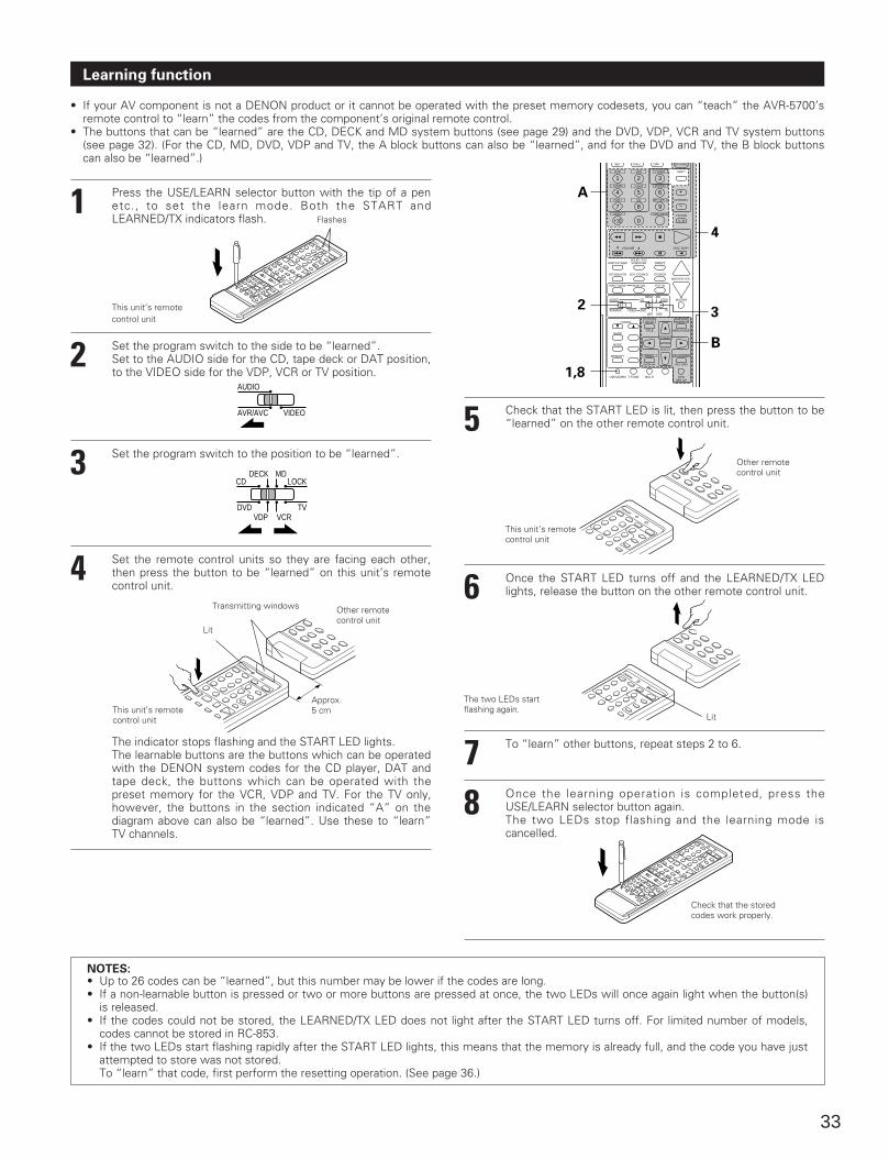
33
Learning function
• If your AV component is not a DENON product or it cannot be operated with the preset memory codesets, you can “teach” the AVR-5700’sremote control to “learn” the codes from the component’s original remote control.
• The buttons that can be “learned” are the CD, DECK and MD system buttons (see page 29) and the DVD, VDP, VCR and TV system buttons(see page 32). (For the CD, MD, DVD, VDP and TV, the A block buttons can also be “learned”, and for the DVD and TV, the B block buttonscan also be “learned”.)
1
2
3
4
Press the USE/LEARN selector button with the tip of a penetc., to set the learn mode. Both the START andLEARNED/TX indicators flash.
Set the program switch to the side to be “learned”. Set to the AUDIO side for the CD, tape deck or DAT position,to the VIDEO side for the VDP, VCR or TV position.
Set the program switch to the position to be “learned”.
Set the remote control units so they are facing each other,then press the button to be “learned” on this unit’s remotecontrol unit.
AVR/AVC VIDEO
AUDIO
DVD TVVDP VCR
CDMD
LOCKDECK
This unit’s remotecontrol unit
Flashes
DVD
HOME THX CINEMA
TUNING
BANDTITLE MENU/GUIDE
MODE
MEMORY
USE/LEARN T.TONE MULTI DVDSET UP
RETURN
PANEL
DISPLAY
ON SCREEN
DOLBY / DTSSURROUND DIRECT
DSP SIMULATION 5CH STEREO STEREO
INPUT MODE ANALOG EXT.IN
MUTING
MASTER VOL.
VOLUME DISC SKIP+
VDP TUNER SHIFT
TV/DBS V.AUX PHONO
VCR-1 CD MD / TAPE-1 CHANNEL
VCR-2 TAPE-2 MON TV/VCR
AVR/AVC VIDEO DVD TV
AUDIO
VDP VCR
CDMD
LOCKDECK
SYSTEMSETUP
SURROUNDPARAMETER
CH SELECT
SELECT
1 2 3
4
SET
A / B
CALL OFF
ENTER
ON / SOURCE
5 6
7 8 9
+10 0
A
2
4
3
B
1,8
Lit
This unit’s remotecontrol unit
Approx. 5 cm
Other remote control unit
Transmitting windows
The indicator stops flashing and the START LED lights.The learnable buttons are the buttons which can be operatedwith the DENON system codes for the CD player, DAT andtape deck, the buttons which can be operated with thepreset memory for the VCR, VDP and TV. For the TV only,however, the buttons in the section indicated “A” on thediagram above can also be “learned”. Use these to “learn”TV channels.
5
6
78
Check that the START LED is lit, then press the button to be“learned” on the other remote control unit.
Once the START LED turns off and the LEARNED/TX LEDlights, release the button on the other remote control unit.
To “learn” other buttons, repeat steps 2 to 6.
Once the learning operation is completed, press theUSE/LEARN selector button again.The two LEDs stop flashing and the learning mode iscancelled.
The two LEDs start flashing again.
Lit
Check that the stored codes work properly.
NOTES:• Up to 26 codes can be “learned”, but this number may be lower if the codes are long.• If a non-learnable button is pressed or two or more buttons are pressed at once, the two LEDs will once again light when the button(s)
is released.• If the codes could not be stored, the LEARNED/TX LED does not light after the START LED turns off. For limited number of models,
codes cannot be stored in RC-853.• If the two LEDs start flashing rapidly after the START LED lights, this means that the memory is already full, and the code you have just
attempted to store was not stored. To “learn” that code, first perform the resetting operation. (See page 36.)
This unit’s remotecontrol unit
Other remote control unit
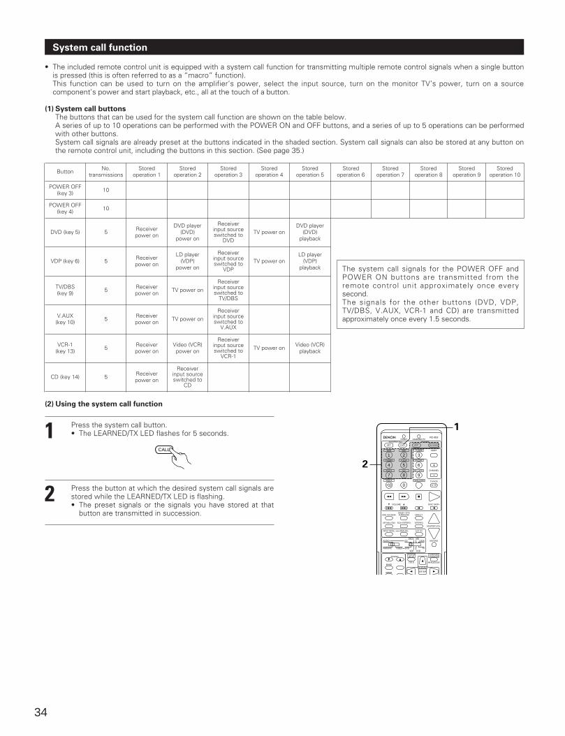
34
System call function
• The included remote control unit is equipped with a system call function for transmitting multiple remote control signals when a single buttonis pressed (this is often referred to as a “macro” function).This function can be used to turn on the amplifier’s power, select the input source, turn on the monitor TV’s power, turn on a sourcecomponent’s power and start playback, etc., all at the touch of a button.
(1) System call buttonsThe buttons that can be used for the system call function are shown on the table below.A series of up to 10 operations can be performed with the POWER ON and OFF buttons, and a series of up to 5 operations can be performedwith other buttons.System call signals are already preset at the buttons indicated in the shaded section. System call signals can also be stored at any button onthe remote control unit, including the buttons in this section. (See page 35.)
Button
POWER OFF(key 3)
POWER OFF(key 4)
DVD (key 5)
VDP (key 6)
TV/DBS(key 9)
V.AUX(key 10)
VCR-1(key 13)
CD (key 14)
No.transmissions
10
10
5
5
5
5
5
5
Receiverpower on
Receiverpower on
Receiverpower on
Receiverpower on
Receiverpower on
Receiverpower on
DVD player(DVD)
power on
LD player(VDP)
power on
TV power on
TV power on
Video (VCR)power on
Receiverinput sourceswitched to
CD
Receiverinput sourceswitched to
DVD
Receiverinput sourceswitched to
VDP
Receiverinput sourceswitched to
TV/DBS
Receiverinput sourceswitched to
V.AUX
Receiverinput sourceswitched to
VCR-1TV power on Video (VCR)
playback
TV power on
TV power on
DVD player(DVD)
playback
LD player(VDP)
playback
Storedoperation 1
Storedoperation 2
Storedoperation 3
Storedoperation 4
Storedoperation 5
Storedoperation 6
Storedoperation 7
Storedoperation 8
Storedoperation 9
Storedoperation 10
The system call signals for the POWER OFF andPOWER ON buttons are transmitted from theremote control unit approximately once everysecond.The signals for the other buttons (DVD, VDP,TV/DBS, V.AUX, VCR-1 and CD) are transmittedapproximately once every 1.5 seconds.
(2) Using the system call function
1
2
Press the system call button.• The LEARNED/TX LED flashes for 5 seconds.
Press the button at which the desired system call signals arestored while the LEARNED/TX LED is flashing.• The preset signals or the signals you have stored at that
button are transmitted in succession.
CALL DVD
START LEARNED/TX
HOME THX CINEMA
TUNING
BANDTITLE MENU/GUIDE
MODE
DOLBY / DTSSURROUND DIRECT
DSP SIMULATION 5CH STEREO STEREO
INPUT MODE ANALOG EXT.IN
MUTING
MASTER VOL.
VOLUME DISC SKIP+
SYSTEM CALL POWER
VDP TUNER SHIFT
TV/DBS V.AUX PHONO
VCR-1 CD MD / TAPE-1 CHANNEL
VCR-2 TAPE-2 MON TV/VCR
AVR/AVC VIDEO DVD TV
AUDIO
VDP VCR
CDMD
LOCKDECK
SYSTEMSETUP
SURROUNDPARAMETER
CH SELECT
RC-853
1 2 3
4
SET
A / B
CALL OFF
ENTER
ON / SOURCE
5 6
7 8 9
+10 0
2
1
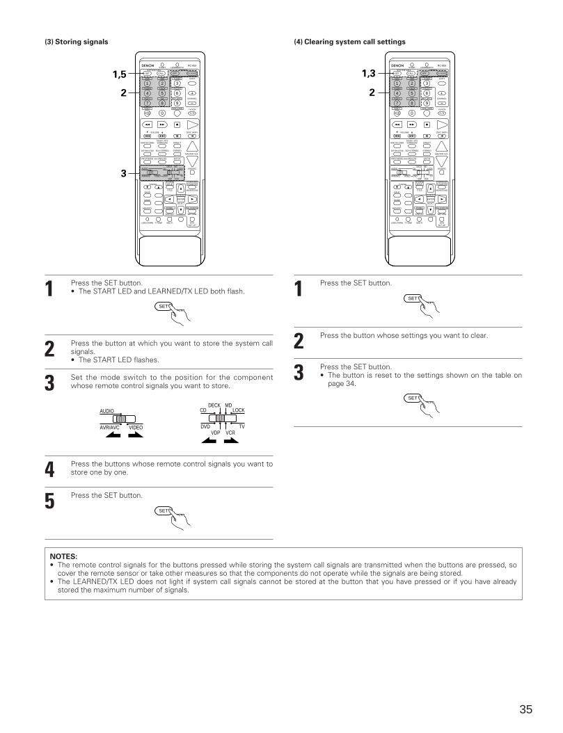
35
(3) Storing signals (4) Clearing system call settings
DVD
START LEARNED/TX
HOME THX CINEMA
TUNING
BANDTITLE MENU/GUIDE
MODE
MEMORY
USE/LEARN T.TONE MULTI DVDSET UP
RETURN
PANEL
DISPLAY
ON SCREEN
DOLBY / DTSSURROUND DIRECT
DSP SIMULATION 5CH STEREO STEREO
INPUT MODE ANALOG EXT.IN
MUTING
MASTER VOL.
VOLUME DISC SKIP+
SYSTEM CALL POWER
VDP TUNER SHIFT
TV/DBS V.AUX PHONO
VCR-1 CD MD / TAPE-1 CHANNEL
VCR-2 TAPE-2 MON TV/VCR
AVR/AVC VIDEO DVD TV
AUDIO
VDP VCR
CDMD
LOCKDECK
SYSTEMSETUP
SURROUNDPARAMETER
CH SELECT
SELECT
RC-853
1 2 3
4
SET
A / B
CALL OFF
ENTER
ON / SOURCE
5 6
7 8 9
+10 0
1,5
2
3
DVD
START LEARNED/TX
HOME THX CINEMA
TUNING
BANDTITLE MENU/GUIDE
MODE
MEMORY
USE/LEARN T.TONE MULTI DVDSET UP
RETURN
PANEL
DISPLAY
ON SCREEN
DOLBY / DTSSURROUND DIRECT
DSP SIMULATION 5CH STEREO STEREO
INPUT MODE ANALOG EXT.IN
MUTING
MASTER VOL.
VOLUME DISC SKIP+
SYSTEM CALL POWER
VDP TUNER SHIFT
TV/DBS V.AUX PHONO
VCR-1 CD MD / TAPE-1 CHANNEL
VCR-2 TAPE-2 MON TV/VCR
AVR/AVC VIDEO DVD TV
AUDIO
VDP VCR
CDMD
LOCKDECK
SYSTEMSETUP
SURROUNDPARAMETER
CH SELECT
SELECT
RC-853
1 2 3
4
SET
A / B
CALL OFF
ENTER
ON / SOURCE
5 6
7 8 9
+10 0
1,3
2
1
2
3
45
Press the SET button.• The START LED and LEARNED/TX LED both flash.
Press the button at which you want to store the system callsignals.• The START LED flashes.
Set the mode switch to the position for the componentwhose remote control signals you want to store.
Press the buttons whose remote control signals you want tostore one by one.
Press the SET button.
SET
AVR/AVC VIDEO
AUDIO
SET
NOTES:• The remote control signals for the buttons pressed while storing the system call signals are transmitted when the buttons are pressed, so
cover the remote sensor or take other measures so that the components do not operate while the signals are being stored.• The LEARNED/TX LED does not light if system call signals cannot be stored at the button that you have pressed or if you have already
stored the maximum number of signals.
1
23
Press the SET button.
Press the button whose settings you want to clear.
Press the SET button.• The button is reset to the settings shown on the table on
page 34.
SET
SET
DVD TVVDP VCR
CDMD
LOCKDECK
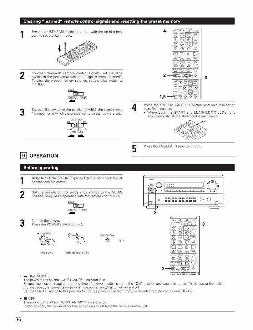
36
Clearing “learned” remote control signals and resetting the preset memory
1
2
3
Press the USE/LEARN selector button with the tip of a pen,etc., to set the learn mode.
To clear “learned” remote control signals, set the slideswitch to the position at which the signals were “learned”.To clear the preset memory settings, set the slide switch to“VIDEO”.
Set the slide switch to the position at which the signals were“learned” or at which the preset memory settings were set.
AVR/AVC VIDEO
AUDIO
DVD TVVDP VCR
CDMD
LOCKDECK
DVD
START LEARNED/TX
HOME THX CINEMA
TUNING
BANDTITLE MENU/GUIDE
MODE
MEMORY
USE/LEARN T.TONE MULTI DVDSET UP
RETURN
PANEL
DISPLAY
ON SCREEN
DOLBY / DTSSURROUND DIRECT
DSP SIMULATION 5CH STEREO STEREO
INPUT MODE ANALOG EXT.IN
MUTING
MASTER VOL.
VOLUME DISC SKIP+
SYSTEM CALL POWER
VDP TUNER SHIFT
TV/DBS V.AUX PHONO
VCR-1 CD MD / TAPE-1 CHANNEL
VCR-2 TAPE-2 MON TV/VCR
AVR/AVC VIDEO DVD TV
AUDIO
VDP VCR
CDMD
LOCKDECK
SYSTEMSETUP
SURROUNDPARAMETER
CH SELECT
SELECT
1 2 3
4
SET
A / B
CALL OFF
ENTER
ON / SOURCE
5 6
7 8 9
+10 0
4
2
1,5
3
4
5
Press the SYSTEM CALL SET button, and hold it in for atleast four seconds. • When both the START and LEARNED/TX LEDs light
simultaneously, all the stored codes are cleared.
Press the USE/LEARN selector button.
Lit
9 OPERATION
Before operating
12
3
Refer to “CONNECTIONS” (pages 6 to 13) and check that allconnections are correct.
Set the remote control unit’s slide switch to the AUDIOposition. (only when operating with the remote control unit)
Turn on the power. Press the POWER switch (button).
AVR/AVC VIDEO
AUDIO
ON / STANDBY
OFF
ON / SOURCE ON/STANDBY
Lights
3
• ¢ ON/STANDBYThe power turns on and “ON/STANDBY” indicator is lit. Several seconds are required from the time the power switch is set to the “ON” position until sound is output. This is due to the built-inmuting circuit that prevents noise when the power switch is turned on and off. Set the POWER switch to this position to turn the power on and off from the included remote control unit (RC-853).
• £ OFFThe power turns off and “ON/STANDBY” indicator is off. In this position, the power cannot be turned on and off from the remote control unit.
DVD
START LEARNED/TX
HOME THX CINEMA
TUNING
DOLBY / DTSSURROUND DIRECT
DSP SIMULATION 5CH STEREO STEREO
INPUT MODE ANALOG EXT.IN
MUTING
MASTER VOL.
VOLUME DISC SKIP+
SYSTEM CALL POWER
VDP TUNER SHIFT
TV/DBS V.AUX PHONO
VCR-1 CD MD / TAPE-1 CHANNEL
VCR-2 TAPE-2 MON TV/VCR
AVR/AVC VIDEO DVD TV
AUDIO
VDP VCR
CDMD
LOCKDECK
SYSTEMSETUP
SURROUNDPARAMETER
RC-853
1 2 3
4
SET
A / B
CALL OFF ON / SOURCE
5 6
7 8 9
+10 0
2
3
(Main unit) (Remote control unit)
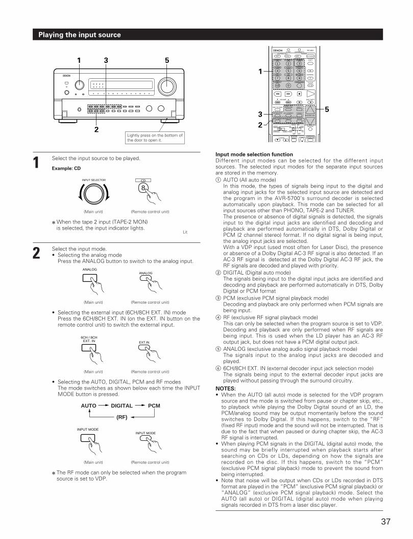
37
Playing the input source
1 Select the input source to be played.
INPUT SELECTOR
(Main unit) (Remote control unit)
2 When the tape 2 input (TAPE-2 MON) is selected, the input indicator lights.
2 Select the input mode.• Selecting the analog mode
Press the ANALOG button to switch to the analog input.
Lit
ANALOG
(Main unit) (Remote control unit)
• Selecting the external input (6CH/8CH EXT. IN) modePress the 6CH/8CH EXT. IN (on the EXT. IN button on theremote control unit) to switch the external input.
6CH / 8CHEXT. IN
(Main unit) (Remote control unit)
• Selecting the AUTO, DIGITAL, PCM and RF modesThe mode switches as shown below each time the INPUTMODE button is pressed.
INPUT MODE
(Main unit) (Remote control unit)
2 The RF mode can only be selected when the programsource is set to VDP.
Input mode selection functionDifferent input modes can be selected for the different inputsources. The selected input modes for the separate input sourcesare stored in the memory.1 AUTO (All auto mode)
In this mode, the types of signals being input to the digital andanalog input jacks for the selected input source are detected andthe program in the AVR-5700’s surround decoder is selectedautomatically upon playback. This mode can be selected for allinput sources other than PHONO, TAPE-2 and TUNER.The presence or absence of digital signals is detected, the signalsinput to the digital input jacks are identified and decoding andplayback are performed automatically in DTS, Dolby Digital orPCM (2 channel stereo) format. If no digital signal is being input,the analog input jacks are selected.With a VDP input (used most often for Laser Disc), the presenceor absence of a Dolby Digital AC-3 RF signal is also detected. If anAC-3 RF signal is detected at the Dolby Digital AC-3 RF jack, theRF signals are decoded and played with priority.
2 DIGITAL (Digital auto mode)The signals being input to the digital input jacks are identified anddecoding and playback are performed automatically in DTS, DolbyDigital or PCM format
3 PCM (exclusive PCM signal playback mode)Decoding and playback are only performed when PCM signals arebeing input.
4 RF (exclusive RF signal playback mode)This can only be selected when the program source is set to VDP.Decoding and playback are only performed when RF signals arebeing input. This is used when the LD player has an AC-3 RFoutput jack, but does not have a PCM digital output jack.
5 ANALOG (exclusive analog audio signal playback mode)The signals input to the analog input jacks are decoded andplayed.
6 6CH/8CH EXT. IN (external decoder input jack selection mode)The signals being input to the external decoder input jacks areplayed without passing through the surround circuitry.
NOTES:• When the AUTO (all auto) mode is selected for the VDP program
source and the mode is switched from pause or chapter skip, etc.,to playback while playing the Dolby Digital sound of an LD, thePCM/analog sound may be output momentarily before the soundswitches to Dolby Digital. If this happens, switch to the “RF”(fixed RF input) mode and the sound will not be interrupted. That isdue to the fact that when paused or during chapter skip, the AC-3RF signal is interrupted.
• When playing PCM signals in the DIGITAL (digital auto) mode, thesound may be briefly interrupted when playback starts aftersearching on CDs or LDs, depending on how the signals arerecorded on the disc. If this happens, switch to the “PCM”(exclusive PCM signal playback) mode to prevent the sound frombeing interrupted.
• Note that noise will be output when CDs or LDs recorded in DTSformat are played in the “PCM” (exclusive PCM signal playback) or“ANALOG” (exclusive PCM signal playback) mode. Select theAUTO (all auto) or DIGITAL (digital auto) mode when playingsignals recorded in DTS from a laser disc player.
1 3 5
2
Example: CD
DVD
START LEARNED/TX
HOME THX CINEMA
TUNING
TITLE MENU/GUIDE
DOLBY / DTSSURROUND DIRECT
DSP SIMULATION 5CH STEREO STEREO
INPUT MODE ANALOG EXT.IN
MUTING
MASTER VOL.
VOLUME DISC SKIP+
SYSTEM CALL POWER
VDP TUNER SHIFT
TV/DBS V.AUX PHONO
VCR-1 CD MD / TAPE-1 CHANNEL
VCR-2 TAPE-2 MON TV/VCR
AVR/AVC VIDEO DVD TV
AUDIO
VDP VCR
CDMD
LOCKDECK
SYSTEMSETUP
SURROUNDPARAMETER
RC-853
1 2 3
4
SET
A / B
CALL OFF ON / SOURCE
5 6
7 8 9
+10 0
1
3
2
5
CD
8
ANALOG
EXT.IN
INPUT MODE
AUTO DIGITAL
(RF)
PCM
Lightly press on the bottom ofthe door to open it.
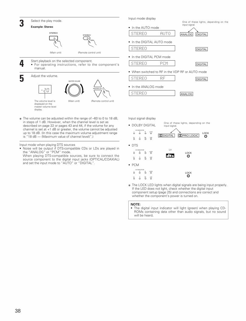
38
3
4 Start playback on the selected component.• For operating instructions, refer to the component’s
manual.
5 Adjust the volume.
2 The volume can be adjusted within the range of –60 to 0 to 18 dB,in steps of 1 dB. However, when the channel level is set asdescribed on page 22 or pages 43 and 44, if the volume for anychannel is set at +1 dB or greater, the volume cannot be adjustedup to 18 dB. (In this case the maximum volume adjustment rangeis “18 dB — (Maximum value of channel level)”.)
Input mode display
ANALOG DIGITAL
DIGITAL
DIGITAL
DIGITAL
ANALOG
• In the DIGITAL AUTO mode
• In the DIGITAL PCM mode
• When switched to RF in the VDP RF or AUTO mode
• In the ANALOG mode
Input signal display
DIGITAL PRO LOGICLOCK
L C R
SL S SR
CH INDICATORLOCK
LFE
LOCKL C R
SL S SR
CH INDICATORLOCK
LFE
L C R
SL S SR
CH INDICATORLOCK
LFE
LOCK
One of these lights, depending on theinput signal.
One of these lights, depending on theinput signal.
• DTSLit
• PCM
2 The LOCK LED lights when digital signals are being input properly.If the LED does not light, check whether the digital inputcomponent setup (page 25) and connections are correct andwhether the component’s power is turned on.
Select the play mode.
STEREO
(Main unit) (Remote control unit)
Example: Stereo
(Main unit) (Remote control unit)The volume level isdisplayed on themaster volume leveldisplay.
NOTE:• The digital input indicator will light (green) when playing CD-
ROMs containing data other than audio signals, but no soundwill be heard.
Input mode when playing DTS sources• Noise will be output if DTS-compatible CDs or LDs are played in
the “ANALOG” or “PCM” mode.When playing DTS-compatible sources, be sure to connect thesource component to the digital input jacks (OPTICAL/COAXIAL)and set the input mode to “AUTO” or “DIGITAL”.
STEREO
MASTER VOLUME
MASTER VOL.
• In the AUTO mode
• DOLBY DIGITAL
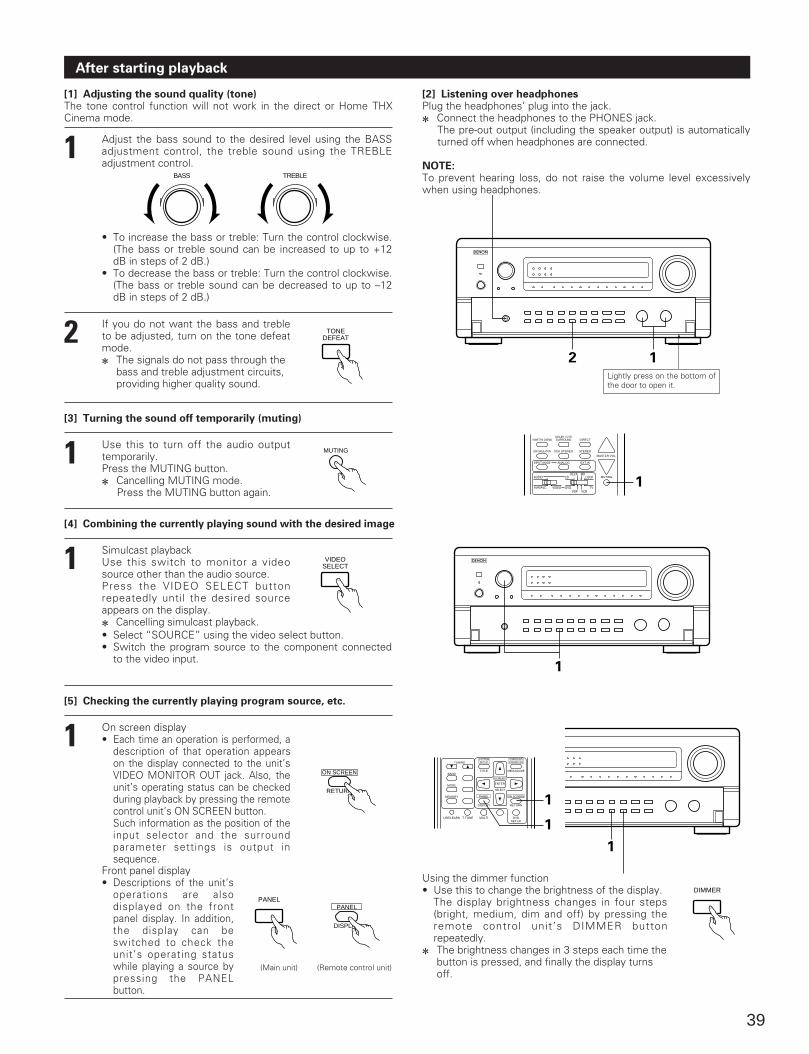
39
After starting playback
[1] Adjusting the sound quality (tone)The tone control function will not work in the direct or Home THXCinema mode.
1 Adjust the bass sound to the desired level using the BASSadjustment control, the treble sound using the TREBLEadjustment control.
BASS
• To increase the bass or treble: Turn the control clockwise.(The bass or treble sound can be increased to up to +12dB in steps of 2 dB.)
• To decrease the bass or treble: Turn the control clockwise.(The bass or treble sound can be decreased to up to –12dB in steps of 2 dB.)
2 If you do not want the bass and trebleto be adjusted, turn on the tone defeatmode.2 The signals do not pass through the
bass and treble adjustment circuits,providing higher quality sound.
[3] Turning the sound off temporarily (muting)
1 Use this to turn off the audio outputtemporarily.Press the MUTING button.2 Cancelling MUTING mode.
Press the MUTING button again.
[4] Combining the currently playing sound with the desired image
1 Simulcast playbackUse this switch to monitor a videosource other than the audio source.Press the VIDEO SELECT buttonrepeatedly until the desired sourceappears on the display.2 Cancelling simulcast playback.
[5] Checking the currently playing program source, etc.
1 On screen display• Each time an operation is performed, a
description of that operation appearson the display connected to the unit’sVIDEO MONITOR OUT jack. Also, theunit’s operating status can be checkedduring playback by pressing the remotecontrol unit’s ON SCREEN button.Such information as the position of theinput selector and the surroundparameter settings is output insequence.
RETURN
ON SCREEN
MUTING
[2] Listening over headphonesPlug the headphones’ plug into the jack.2 Connect the headphones to the PHONES jack.
The pre-out output (including the speaker output) is automaticallyturned off when headphones are connected.
NOTE:To prevent hearing loss, do not raise the volume level excessivelywhen using headphones.
2 1
HOME THX CINEMADOLBY / DTSSURROUND DIRECT
DSP SIMULATION 5CH STEREO STEREO
INPUT MODE ANALOG EXT.IN
MUTING
MASTER VOL.
AVR/AVC VIDEO DVD TV
AUDIO
VDP VCR
CDMD
LOCKDECK
1
1
TUNING
BANDTITLE MENU/GUIDE
MODE
MEMORY
USE/LEARN T.TONE MULTI DVDSET UP
RETURN
PANEL
DISPLAY
ON SCREEN
SYSTEMSETUP
SURROUNDPARAMETER
CH SELECT
SELECT
ENTER
1
1
Front panel display• Descriptions of the unit’s
operations are alsodisplayed on the frontpanel display. In addition,the display can beswitched to check theunit’s operating statuswhile playing a source bypressing the PANELbutton.
TONEDEFEAT
VIDEOSELECT
(Remote control unit)
Using the dimmer function• Use this to change the brightness of the display.
The display brightness changes in four steps(bright, medium, dim and off) by pressing theremote control unit’s DIMMER buttonrepeatedly.
2 The brightness changes in 3 steps each time thebutton is pressed, and finally the display turnsoff.
DIMMERPANEL
(Main unit)
TREBLE
1
PANEL
DISPLAY
• Select “SOURCE” using the video select button.• Switch the program source to the component connected
to the video input.
Lightly press on the bottom ofthe door to open it.
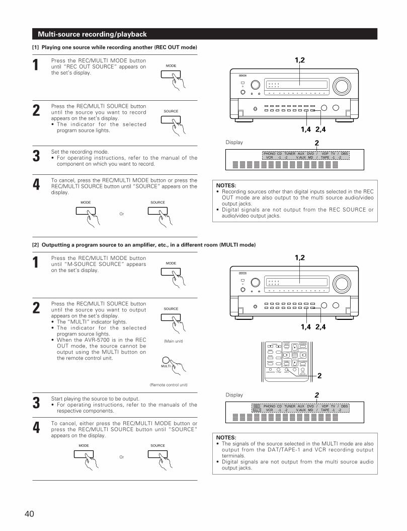
40
Multi-source recording/playback
[1] Playing one source while recording another (REC OUT mode)
1 Press the REC/MULTI MODE buttonuntil “REC OUT SOURCE” appears onthe set’s display.
MODE
2 Press the REC/MULTI SOURCE buttonuntil the source you want to recordappears on the set’s display.• The indicator for the selected
program source lights.
3 Set the recording mode.• For operating instructions, refer to the manual of the
component on which you want to record.
4 To cancel, press the REC/MULTI MODE button or press theREC/MULTI SOURCE button until “SOURCE” appears on thedisplay.
SOURCE
MODE
Or
[2] Outputting a program source to an amplifier, etc., in a different room (MULTI mode)
1 Press the REC/MULTI MODE buttonuntil “M-SOURCE SOURCE” appearson the set’s display.
MODE
2 Press the REC/MULTI SOURCE buttonuntil the source you want to outputappears on the set’s display.• The “MULTI” indicator lights.• The indicator for the selected
program source lights.• When the AVR-5700 is in the REC
OUT mode, the source cannot beoutput using the MULTI button onthe remote control unit.
3 Start playing the source to be output.• For operating instructions, refer to the manuals of the
respective components.
4 To cancel, either press the REC/MULTI MODE button orpress the REC/MULTI SOURCE button until “SOURCE”appears on the display.
SOURCE
(Main unit)
MULTI
(Remote control unit)
1,2
1,4 2,4
Display
VCR -1 -2 V.AUX MD / TAPE -1 -2PHONO CD TUNER AUX DVD / VDP TV / DBS
2
NOTES:• Recording sources other than digital inputs selected in the REC
OUT mode are also output to the multi source audio/videooutput jacks.
• Digital signals are not output from the REC SOURCE oraudio/video output jacks.
TUNING
BANDTITLE MENU/GUIDE
MODE
MEMORY
USE/LEARN T.TONE MULTI DVDSET UP
RETURN
PANEL
DISPLAY
ON SCREEN
SYSTEMSETUP
SURROUNDPARAMETER
CH SELECT
SELECT
ENTER
2
Display
VCR -1 -2 V.AUX MD / TAPE -1 -2PHONO CD TUNER AUX DVD / VDP TV / DBS
2REC
MULTI
NOTES:• The signals of the source selected in the MULTI mode are also
output from the DAT/TAPE-1 and VCR recording outputterminals.
• Digital signals are not output from the multi source audiooutput jacks.
SOURCE
MODE
Or
SOURCE
1,2
1,4 2,4
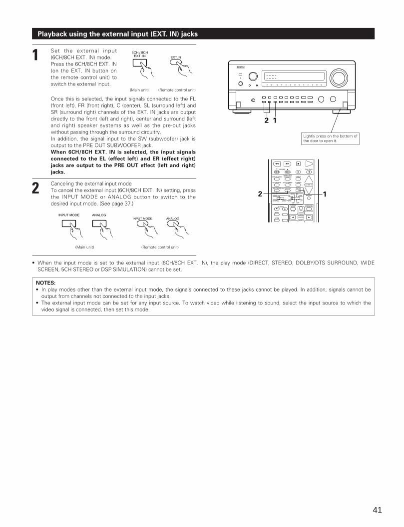
41
Playback using the external input (EXT. IN) jacks
1 Set the external input(6CH/8CH EXT. IN) mode.Press the 6CH/8CH EXT. IN(on the EXT. IN button onthe remote control unit) toswitch the external input.
6CH / 8CHEXT. IN
(Main unit) (Remote control unit)
Once this is selected, the input signals connected to the FL(front left), FR (front right), C (center), SL (surround left) andSR (surround right) channels of the EXT. IN jacks are outputdirectly to the front (left and right), center and surround (leftand right) speaker systems as well as the pre-out jackswithout passing through the surround circuitry.In addition, the signal input to the SW (subwoofer) jack isoutput to the PRE OUT SUBWOOFER jack.When 6CH/8CH EXT. IN is selected, the input signals
connected to the EL (effect left) and ER (effect right)
jacks are output to the PRE OUT effect (left and right)
jacks.
2 Canceling the external input modeTo cancel the external input (6CH/8CH EXT. IN) setting, pressthe INPUT MODE or ANALOG button to switch to thedesired input mode. (See page 37.)
(Main unit) (Remote control unit)
• When the input mode is set to the external input (6CH/8CH EXT. IN), the play mode (DIRECT, STEREO, DOLBY/DTS SURROUND, WIDESCREEN, 5CH STEREO or DSP SIMULATION) cannot be set.
NOTES:
• In play modes other than the external input mode, the signals connected to these jacks cannot be played. In addition, signals cannot beoutput from channels not connected to the input jacks.
• The external input mode can be set for any input source. To watch video while listening to sound, select the input source to which thevideo signal is connected, then set this mode.
2 1
HOME THX CINEMA
TUNING
BANDTITLE MENU/GUIDE
MODE
DOLBY / DTSSURROUND DIRECT
DSP SIMULATION 5CH STEREO STEREO
INPUT MODE ANALOG EXT.IN
MUTING
MASTER VOL.
VOLUME DISC SKIP+
AVR/AVC VIDEO DVD TV
AUDIO
VDP VCR
CDMD
LOCKDECK
SYSTEMSETUP
SURROUNDPARAMETER
CH SELECT
SELECT
ENTER
2 1
Lightly press on the bottom ofthe door to open it.
EXT.IN
ANALOGINPUT MODE ANALOG
INPUT MODE
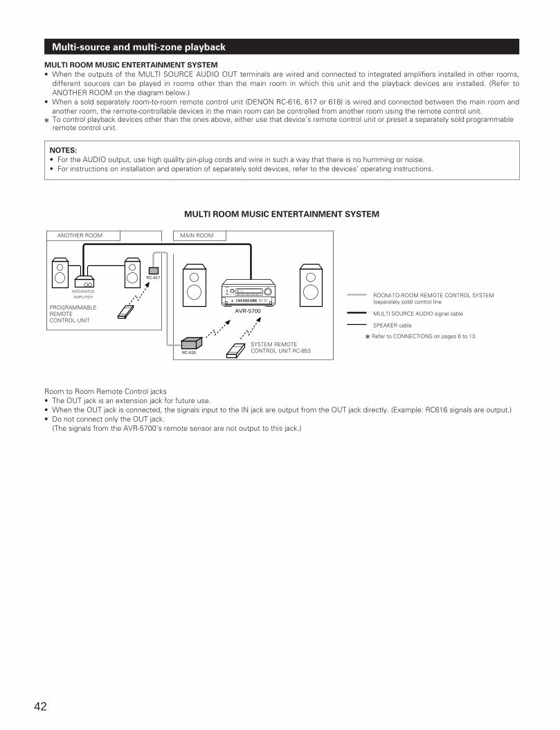
42
MULTI ROOM MUSIC ENTERTAINMENT SYSTEM
• When the outputs of the MULTI SOURCE AUDIO OUT terminals are wired and connected to integrated amplifiers installed in other rooms,different sources can be played in rooms other than the main room in which this unit and the playback devices are installed. (Refer toANOTHER ROOM on the diagram below.)
• When a sold separately room-to-room remote control unit (DENON RC-616, 617 or 618) is wired and connected between the main room andanother room, the remote-controllable devices in the main room can be controlled from another room using the remote control unit.
2 To control playback devices other than the ones above, either use that device’s remote control unit or preset a separately sold programmableremote control unit.
NOTES:
• For the AUDIO output, use high quality pin-plug cords and wire in such a way that there is no humming or noise.• For instructions on installation and operation of separately sold devices, refer to the devices’ operating instructions.
RC-617
AVR-5700
RC-616
MULTI ROOM MUSIC ENTERTAINMENT SYSTEM
PROGRAMMABLEREMOTECONTROL UNIT
SYSTEM REMOTECONTROL UNIT RC-853
Multi-source and multi-zone playback
Room to Room Remote Control jacks• The OUT jack is an extension jack for future use.• When the OUT jack is connected, the signals input to the IN jack are output from the OUT jack directly. (Example: RC616 signals are output.)• Do not connect only the OUT jack.
(The signals from the AVR-5700’s remote sensor are not output to this jack.)
ROOM-TO-ROOM REMOTE CONTROL SYSTEM(separately sold) control line
MULTI SOURCE AUDIO signal cable
SPEAKER cable
2 Refer to CONNECTIONS on pages 6 to 13.
ANOTHER ROOM MAIN ROOM
INTEGRATEDAMPLIFIER
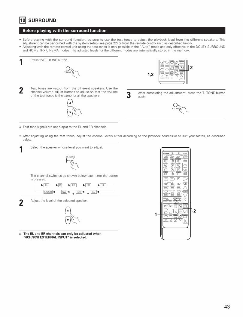
43
Before playing with the surround function
• Before playing with the surround function, be sure to use the test tones to adjust the playback level from the different speakers. Thisadjustment can be performed with the system setup (see page 22) or from the remote control unit, as described below.
• Adjusting with the remote control unit using the test tones is only possible in the “Auto” mode and only effective in the DOLBY SURROUNDand HOME THX CINEMA modes. The adjusted levels for the different modes are automatically stored in the memory.
1 Press the T. TONE button.
T.TONE
2 Test tones are output from the different speakers. Use thechannel volume adjust buttons to adjust so that the volumeof the test tones is the same for all the speakers.
TUNING
BANDTITLE MENU/GUIDE
MODE
MEMORY
USE/LEARN T.TONE MULTI DVDSET UP
RETURN
PANEL
DISPLAY
ON SCREEN
SYSTEMSETUP
SURROUNDPARAMETER
CH SELECT
SELECT
ENTER
1,3
2
3 After completing the adjustment, press the T. TONE buttonagain.
T.TONE
2 Test tone signals are not output to the EL and ER channels.
• After adjusting using the test tones, adjust the channel levels either according to the playback sources or to suit your tastes, as describedbelow.
1 Select the speaker whose level you want to adjust.
The channel switches as shown below each time the buttonis pressed.
2 Adjust the level of the selected speaker.
2 The EL and ER channels can only be adjusted when“6CH/8CH EXTERNAL INPUT” is selected.
10 SURROUND
FL 1 C 1 FR 1 SL1 1 SR
SW 0 ER 0 EL 0FADER 022
CH SELECT
ENTER
21
DVD
START LEARNED/TX
HOME THX CINEMA
TUNING
BANDTITLE MENU/GUIDE
MODE
MEMORY
USE/LEARN T.TONE MULTI DVDSET UP
RETURN
PANEL
DISPLAY
ON SCREEN
DOLBY / DTSSURROUND DIRECT
DSP SIMULATION 5CH STEREO STEREO
INPUT MODE ANALOG EXT.IN
MUTING
MASTER VOL.
VOLUME DISC SKIP+
SYSTEM CALL POWER
VDP TUNER SHIFT
TV/DBS V.AUX PHONO
VCR-1 CD MD / TAPE-1 CHANNEL
VCR-2 TAPE-2 MON TV/VCR
AVR/AVC VIDEO DVD TV
AUDIO
VDP VCR
CDMD
LOCKDECK
SYSTEMSETUP
SURROUNDPARAMETER
CH SELECT
SELECT
RC-853
1 2 3
4
SET
A / B
CALL OFF
ENTER
ON / SOURCE
5 6
7 8 9
+10 0
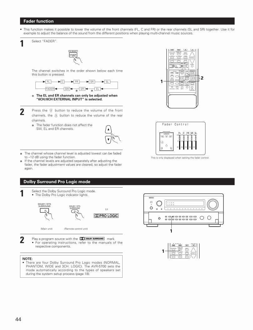
44
Fader function
• This function makes it possible to lower the volume of the front channels (FL, C and FR) or the rear channels (SL and SR) together. Use it forexample to adjust the balance of the sound from the different positions when playing multi-channel music sources.
1 Select “FADER”.
The channel switches in the order shown below each timethis button is pressed.
2 Press the button to reduce the volume of the frontchannels, the button to reduce the volume of the rearchannels.
2 The channel whose channel level is adjusted lowest can be fadedto –12 dB using the fader function.
2 If the channel levels are adjusted separately after adjusting thefader, the fader adjustment values are cleared, so adjust the faderagain.
This is only displayed when setting the fader control.
Dolby Surround Pro Logic mode
1 Select the Dolby Surround Pro Logic mode.• The Dolby Pro Logic indicator lights.
(Main unit) (Remote control unit)
NOTE:• There are four Dolby Surround Pro Logic modes (NORMAL,
PHANTOM, WIDE and 3CH. LOGIC). The AVR-5700 sets themode automatically according to the types of speakers setduring the system setup process (page 18).
2 Play a program source with the mark.• For operating instructions, refer to the manuals of the
respective components.
Lit
2 The fader function does not affect theSW, EL and ER channels.
FL 1 C 1 FR 1 SL1 1 SR
SW 0 ER 0 EL 0FADER 0
CH SELECT
ENTER
21
HOME THX CINEMA
TUNING
BANDTITLE MENU/GUIDE
MODE
MEMORY
USE/LEARN T.TONE MULTI DVDSET UP
RETURN
PANEL
DISPLAY
ON SCREEN
DOLBY / DTSSURROUND DIRECT
DSP SIMULATION 5CH STEREO STEREO
INPUT MODE ANALOG EXT.IN
MUTING
MASTER VOL.
AVR/AVC VIDEO DVD TV
AUDIO
VDP VCR
CDMD
LOCKDECK
SYSTEMSETUP
SURROUNDPARAMETER
CH SELECT
SELECT
ENTER
HOME THX CINEMADOLBY / DTSSURROUND DIRECT
DSP SIMULATION 5CH STEREO STEREO
INPUT MODE ANALOG EXT.IN
MASTER VOL.
VOLUME DISC SKIP+
1
1
DOLBY / DTSSURROUND DOLBY / DTS
SURROUND
2 The EL and ER channels can only be adjusted when“6CH/8CH EXTERNAL INPUT” is selected.
22
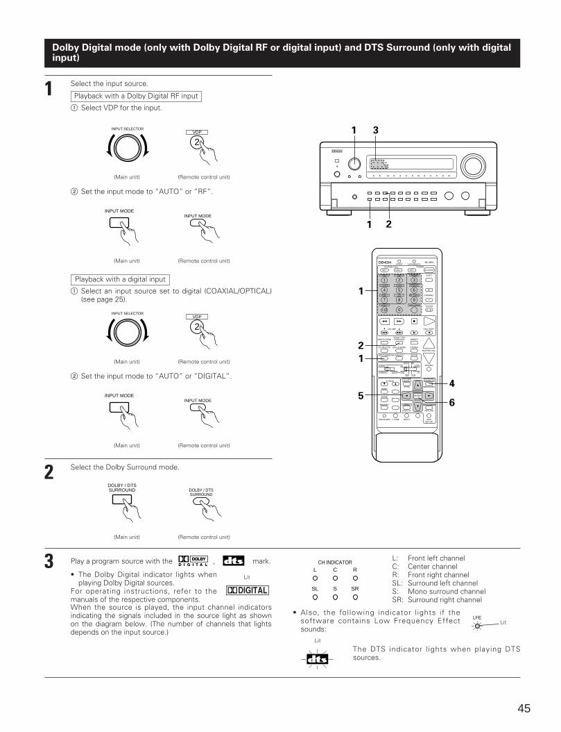
45
Dolby Digital mode (only with Dolby Digital RF or digital input) and DTS Surround (only with digitalinput)
1 Select the input source.
Playback with a Dolby Digital RF input
1 Select VDP for the input.
INPUT SELECTOR
(Main unit) (Remote control unit)
2 Set the input mode to “AUTO” or “RF”.
(Main unit) (Remote control unit)
Playback with a digital input
1 Select an input source set to digital (COAXIAL/OPTICAL)(see page 25).
2 Set the input mode to “AUTO” or “DIGITAL”.
2 Select the Dolby Surround mode.
1 3
1 2
3 Play a program source with the , mark.
• The Dolby Digital indicator lights whenplaying Dolby Digital sources.
For operating instructions, refer to themanuals of the respective components.When the source is played, the input channel indicatorsindicating the signals included in the source light as shownon the diagram below. (The number of channels that lightsdepends on the input source.)
L: Front left channelC: Center channelR: Front right channelSL: Surround left channelS: Mono surround channelSR: Surround right channel
L CCH INDICATOR
R
SL S SR
• Also, the following indicator l ights if thesoftware contains Low Frequency Effectsounds:
The DTS indicator l ights when playing DTSsources.
Lit
Lit
VDP
2
INPUT MODEINPUT MODE
INPUT SELECTOR
(Main unit) (Remote control unit)
VDP
2
(Main unit) (Remote control unit)
INPUT MODEINPUT MODE
(Main unit) (Remote control unit)
DOLBY / DTSSURROUND DOLBY / DTS
SURROUND
DVD
START LEARNED/TX
HOME THX CINEMA
TUNING
BANDTITLE MENU/GUIDE
MODE
MEMORY
USE/LEARN T.TONE MULTI DVDSET UP
RETURN
PANEL
DISPLAY
ON SCREEN
DOLBY / DTSSURROUND DIRECT
DSP SIMULATION 5CH STEREO STEREO
INPUT MODE ANALOG EXT.IN
MUTING
MASTER VOL.
VOLUME DISC SKIP+
SYSTEM CALL POWER
VDP TUNER SHIFT
TV/DBS V.AUX PHONO
VCR-1 CD MD / TAPE-1 CHANNEL
VCR-2 TAPE-2 MON TV/VCR
AVR/AVC VIDEO DVD TV
AUDIO
VDP VCR
CDMD
LOCKDECK
SYSTEMSETUP
SURROUNDPARAMETER
CH SELECT
SELECT
RC-853
1 2 3
4
SET
A / B
CALL OFF
ENTER
ON / SOURCE
5 6
7 8 9
+10 0
1
2
1
5
4
6
LFELit
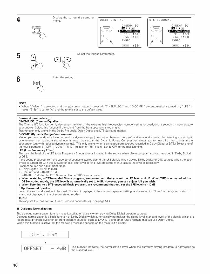
NOTE:• When “Default” is selected and the cursor button is pressed, “CINEMA EQ.” and “D.COMP.” are automatically turned off, “LFE” is
reset, “S.Sp” is set to “A” and the tone is set to the default value.
46
4 Display the surround parametermenu.
MENU/GUIDE
SURROUNDPARAMETER
5 Select the various parameters.
6 Enter the setting.
ENTER
Surround parameters 1CINEMA EQ. (Cinema Equalizer):The Cinema EQ function gently decreases the level of the extreme high frequencies, compensating for overly-bright sounding motion picturesoundtracks. Select this function if the sound from the front speakers is too bright.This function only works in the Dolby Pro Logic, Dolby Digital and DTS Surround modes.D.COMP. (Dynamic Range Compression):Motion picture soundtracks have tremendous dynamic range (the contrast between very soft and very loud sounds). For listening late at night,or whenever the maximum sound level is lower than usual, the Dynamic Range Compression allows you to hear all of the sounds in thesoundtrack (but with reduced dynamic range). (This only works when playing program sources recorded in Dolby Digital or DTS.) Select one ofthe four parameters (“OFF”, “LOW”, “MID” (middle) or “HI” (high)). Set to OFF for normal listening.LFE (Low Frequency Effect):This sets the level of the LFE (Low Frequency Effect) sounds included in the source when playing program sources recorded in Dolby Digitalor DTS.If the sound produced from the subwoofer sounds distorted due to the LFE signals when playing Dolby Digital or DTS sources when the peaklimiter is turned off with the subwoofer peak limit level setting (system setup menu), adjust the level as necessary.Program source and adjustment range1. Dolby Digital: –10 dB to 0 dB2. DTS Surround (–10 dB to 0 dB)
(–10 dB to 0 dB for the DTS Surround Home THX Cinema mode)2 When watching a DTS-encoded Movie program, we recommend that you set the LFE level at 0 dB. When THX is activated with a
DTS-encoded movie, the LFE level is automatically set to 0 dB. However, you can adjust it if you wish.
2 When listening to a DTS-encoded Music program, we recommend that you set the LFE level to –10 dB.
S.Sp (Surround Speaker):Select the surround speaker to be used. This is not displayed if the surround speaker setting has been set to “None” in the system setup. Itis also not displayed in the direct or stereo modes.TONE:This adjusts the tone control. (See “Surround parameters 2” on page 51.)
2 Dialogue Normalization
The dialogue normalization function is activated automatically when playing Dolby Digital program sources.Dialogue normalization is a basic function of Dolby Digital which automatically normalizes the dialog level (standard level) of the signals which arerecorded at different levels for different program sources, such as DVD, DTV and other future formats that will use Dolby Digital.When this function is activated, the following message appears on the main unit’s display:
The number indicates the normalization level when the currently playing program is normalized tothe standard level.
DIAL.NORM
OFFSET - 4dB
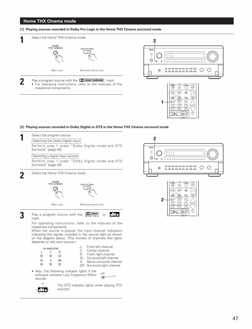
47
Home THX Cinema mode
[1] Playing sources recorded in Dolby Pro Logic in the Home THX Cinema surround mode
1 Select the Home THX Cinema mode.
(Main unit) (Remote control unit)
HOMETHX CINEMA
2 Play a program source with the mark.• For operating instructions, refer to the manuals of the
respective components.
2
1 Select the program source
Selecting the Dolby Digital input
Perform step 1 under “Dolby Digital mode and DTSSurround” (page 45).
[2] Playing sources recorded in Dolby Digital or DTS in the Home THX Cinema surround mode
Selecting a digital input source
Perform step 1 under “Dolby Digital mode and DTSSurround” (page 45).
2 Select the Home THX Cinema mode.
(Main unit) (Remote control unit)
3 Play a program source with the or mark.For operating instructions, refer to the manuals of therespective components.When the source is played, the input channel indicatorsindicating the signals included in the source light as shownon the diagram below. (The number of channels that lightsdepends on the input source.)
L: Front left channelC: Center channelR: Front right channelSL: Surround left channelS: Mono surround channelSR: Surround right channel
L CCH INDICATOR
R
SL S SR
• Also, the following indicator lights if thesoftware contains Low Frequency Effectsounds:
The DTS indicator lights when playing DTSsources.
Lit
HOME THX CINEMA
HOME THX CINEMADOLBY / DTSSURROUND DIRECT
DSP SIMULATION 5CH STEREO STEREO
INPUT MODE ANALOG EXT.IN
MUTING
MASTER VOL.
VOLUME DISC SKIP+
VCR-2 TAPE-2 MON TV/VCR
AVR/AVC VIDEO DVD TV
AUDIO
VDP VCR
CDMD
LOCKDECK
SYSTEM SURROUND
A / B
7 8 9
+10 0
1
2
HOME THX CINEMADOLBY / DTSSURROUND DIRECT
DSP SIMULATION 5CH STEREO STEREO
INPUT MODE ANALOG EXT.IN
MUTING
MASTER VOL.
VOLUME DISC SKIP+
VCR-2 TAPE-2 MON TV/VCR
AVR/AVC VIDEO DVD TV
AUDIO
VDP VCR
CDMD
LOCKDECK
SYSTEM SURROUND
A / B
7 8 9
+10 0
2
HOMETHX CINEMA HOME THX CINEMA
LFELit
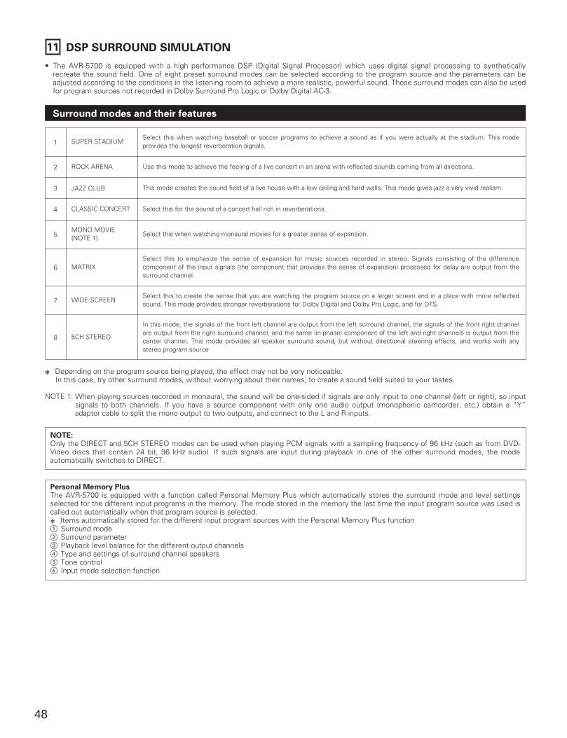
48
11 DSP SURROUND SIMULATION
• The AVR-5700 is equipped with a high performance DSP (Digital Signal Processor) which uses digital signal processing to syntheticallyrecreate the sound field. One of eight preset surround modes can be selected according to the program source and the parameters can beadjusted according to the conditions in the listening room to achieve a more realistic, powerful sound. These surround modes can also be usedfor program sources not recorded in Dolby Surround Pro Logic or Dolby Digital AC-3.
Surround modes and their features
SUPER STADIUMSelect this when watching baseball or soccer programs to achieve a sound as if you were actually at the stadium. This modeprovides the longest reverberation signals.1
ROCK ARENA Use this mode to achieve the feeling of a live concert in an arena with reflected sounds coming from all directions.2
JAZZ CLUB This mode creates the sound field of a live house with a low ceiling and hard walls. This mode gives jazz a very vivid realism.3
CLASSIC CONCERT Select this for the sound of a concert hall rich in reverberations.
MONO MOVIE(NOTE 1)
Select this when watching monaural movies for a greater sense of expansion.
4
5
MATRIXSelect this to emphasize the sense of expansion for music sources recorded in stereo. Signals consisting of the differencecomponent of the input signals (the component that provides the sense of expansion) processed for delay are output from thesurround channel.
6
WIDE SCREENSelect this to create the sense that you are watching the program source on a larger screen and in a place with more reflectedsound. This mode provides stronger reverberations for Dolby Digital and Dolby Pro Logic, and for DTS.7
5CH STEREO
In this mode, the signals of the front left channel are output from the left surround channel, the signals of the front right channelare output from the right surround channel, and the same (in-phase) component of the left and right channels is output from thecenter channel. This mode provides all speaker surround sound, but without directional steering effects, and works with anystereo program source
8
2 Depending on the program source being played, the effect may not be very noticeable. In this case, try other surround modes, without worrying about their names, to create a sound field suited to your tastes.
NOTE 1: When playing sources recorded in monaural, the sound will be one-sided if signals are only input to one channel (left or right), so inputsignals to both channels. If you have a source component with only one audio output (monophonic camcorder, etc.) obtain a “Y”adaptor cable to split the mono output to two outputs, and connect to the L and R inputs.
NOTE:Only the DIRECT and 5CH STEREO modes can be used when playing PCM signals with a sampling frequency of 96 kHz (such as from DVD-Video discs that contain 24 bit, 96 kHz audio). If such signals are input during playback in one of the other surround modes, the modeautomatically switches to DIRECT.
Personal Memory PlusThe AVR-5700 is equipped with a function called Personal Memory Plus which automatically stores the surround mode and level settingsselected for the different input programs in the memory. The mode stored in the memory the last time the input program source was used iscalled out automatically when that program source is selected.2 Items automatically stored for the different input program sources with the Personal Memory Plus function1 Surround mode2 Surround parameter3 Playback level balance for the different output channels4 Type and settings of surround channel speakers5 Tone control6 Input mode selection function
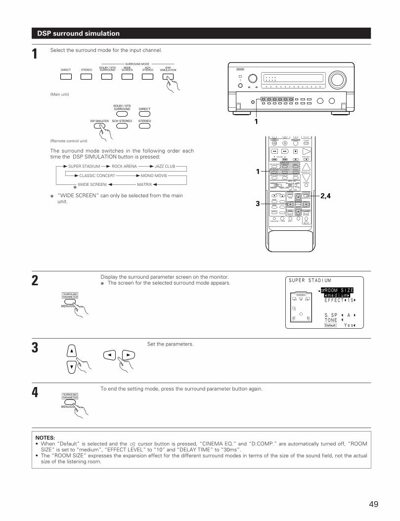
49
DSP surround simulation
1 Select the surround mode for the input channel.
DSPSIMULATIONDIRECT STEREO
DOLBY / DTSSURROUND
WIDESCREEN
5CHSTEREO
SURROUND MODE
(Main unit)
(Remote control unit)
The surround mode switches in the following order eachtime the DSP SIMULATION button is pressed:
2 “WIDE SCREEN” can only be selected from the mainunit.
2 Display the surround parameter screen on the monitor.2 The screen for the selected surround mode appears.
MENU/GUIDE
SURROUNDPARAMETER
3 Set the parameters.
4 To end the setting mode, press the surround parameter button again.
MENU/GUIDE
SURROUNDPARAMETER
NOTES:• When “Default” is selected and the cursor button is pressed, “CINEMA EQ.” and “D.COMP.” are automatically turned off, “ROOM
SIZE” is set to “medium”, “EFFECT LEVEL” to “10” and “DELAY TIME” to “30ms”.• The “ROOM SIZE” expresses the expansion effect for the different surround modes in terms of the size of the sound field, not the actual
size of the listening room.
11
0 0
1
1 1
ROCK ARENA JAZZ CLUB
MONO MOVIECLASSIC CONCERT
(WIDE SCREEN) MATRIX
SUPER STADIUM
2
HOME THX CINEMA
TUNING
BANDTITLE MENU/GUIDE
MODE
MEMORY
USE/LEARN T.TONE MULTI DVDSET UP
RETURN
PANEL
DISPLAY
ON SCREEN
DOLBY / DTSSURROUND DIRECT
DSP SIMULATION 5CH STEREO STEREO
INPUT MODE ANALOG EXT.IN
MUTING
MASTER VOL.
VOLUME DISC SKIP+
VCR-2 TAPE-2 MON TV/VCR
AVR/AVC VIDEO DVD TV
AUDIO
VDP VCR
CDMD
LOCKDECK
SYSTEMSETUP
SURROUNDPARAMETER
CH SELECT
SELECT
A / B
ENTER
7 8 9
+10 0
1
32,4
1
DOLBY / DTSSURROUND DIRECT
DSP SIMULATION 5CH STEREO STEREO
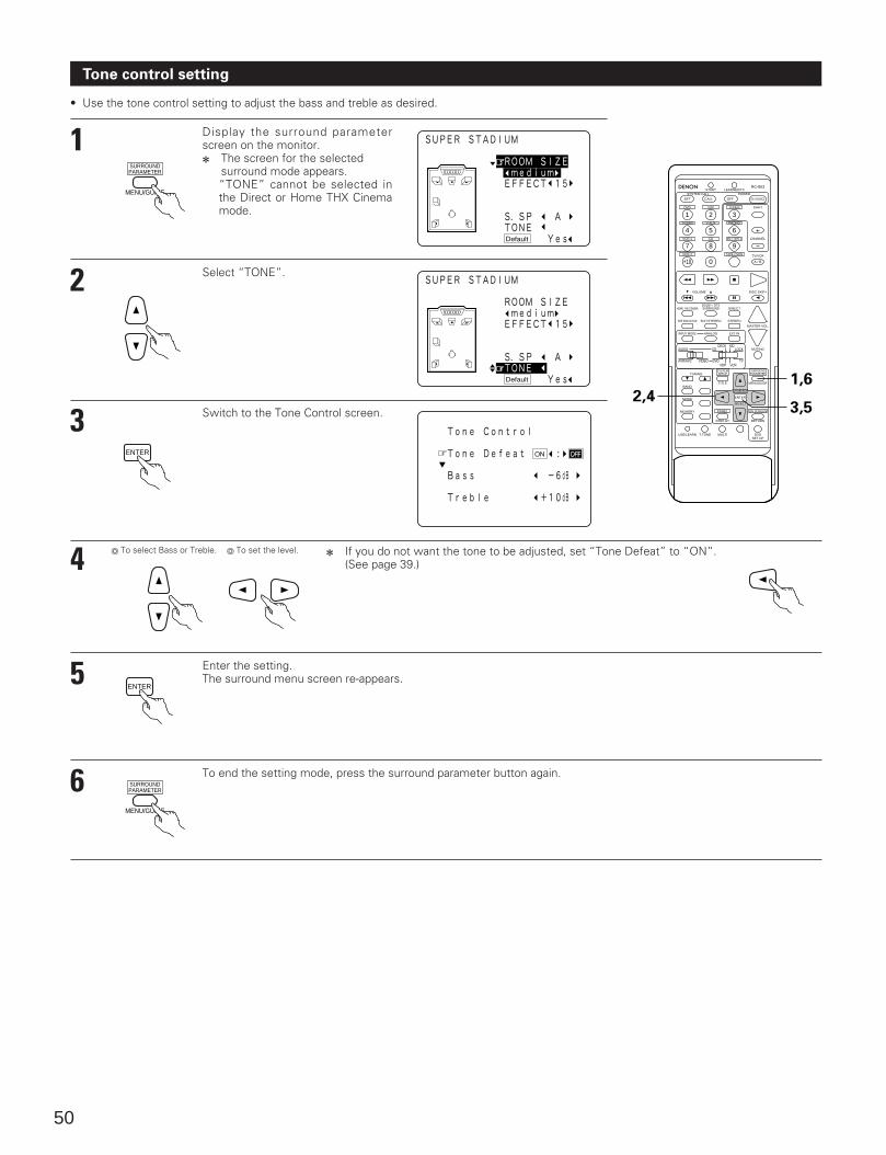
50
Tone control setting
• Use the tone control setting to adjust the bass and treble as desired.
1 Display the surround parameterscreen on the monitor.2 The screen for the selected
surround mode appears.“TONE” cannot be selected inthe Direct or Home THX Cinemamode.
MENU/GUIDE
SURROUNDPARAMETER
2 Select “TONE”.
3 Switch to the Tone Control screen.
ENTER
4 2 If you do not want the tone to be adjusted, set “Tone Defeat” to “ON”.(See page 39.)
o To select Bass or Treble. o To set the level.
5 Enter the setting.The surround menu screen re-appears.
ENTER
6 To end the setting mode, press the surround parameter button again.
MENU/GUIDE
SURROUNDPARAMETER
DVD
START LEARNED/TX
HOME THX CINEMA
TUNING
BANDTITLE MENU/GUIDE
MODE
MEMORY
USE/LEARN T.TONE MULTI DVDSET UP
RETURN
PANEL
DISPLAY
ON SCREEN
DOLBY / DTSSURROUND DIRECT
DSP SIMULATION 5CH STEREO STEREO
INPUT MODE ANALOG EXT.IN
MUTING
MASTER VOL.
VOLUME DISC SKIP+
SYSTEM CALL POWER
VDP TUNER SHIFT
TV/DBS V.AUX PHONO
VCR-1 CD MD / TAPE-1 CHANNEL
VCR-2 TAPE-2 MON TV/VCR
AVR/AVC VIDEO DVD TV
AUDIO
VDP VCR
CDMD
LOCKDECK
SYSTEMSETUP
SURROUNDPARAMETER
CH SELECT
SELECT
RC-853
1 2 3
4
SET
A / B
CALL OFF
ENTER
ON / SOURCE
5 6
7 8 9
+10 0
2,41,6
3,5
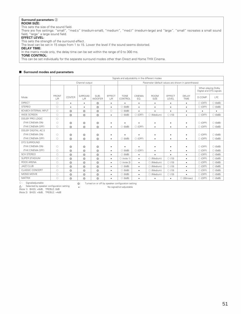
51
Surround parameters 2ROOM SIZE:This sets the size of the sound field.There are five settings: “small”, “med.s” (medium-small), “medium”, “med.l” (medium-large) and “large”. “small” recreates a small soundfield, “large” a large sound field.EFFECT LEVEL:This sets the strength of the surround effect.The level can be set in 15 steps from 1 to 15. Lower the level if the sound seems distorted.DELAY TIME:In the matrix mode only, the delay time can be set within the range of 0 to 300 ms.TONE CONTROL:This can be set individually for the separate surround modes other than Direct and Home THX Cinema.
A : Signal/adjustableC : Selected by speaker configuration setting(Note 1) BASS: +6dB, TREBLE: 0dB(Note 2) BASS: +8dB, TREBLE: +4dB
2 Surround modes and parameters
FRONTL/R
A
A
A
A
A
A
A
A
A
A
A
A
A
A
A
A
A
A
E
E
o
o
o
o
o
o
o
o
o
o
o
o
o
o
o
E
E
o
o
o
o
o
o
o
o
o
o
o
o
o
o
o
o
o
o
o
o
o
o
o
o
o
o
o
o
o
o
o
o
E
E
A
E
E
E
E
E
E
E
E
E
E
E
E
E
E
E
A (0dB)
A (0dB)
A (0dB)
E
A (0dB)
E
A (0dB)
E
A (0dB)
A (0dB)
A (note 1)
A (note 2)
A (0dB)
A (0dB)
A (0dB)
A (0dB)
E
E
E
A (OFF)
E
A (OFF)
E
A (OFF)
E
A (OFF)
E
E
E
E
E
E
E
E
E
E
A (Medium)
E
E
E
E
E
E
E
A (Medium)
A (Medium)
A (Medium)
A (Medium)
A (Medium)
E
E
E
E
A (10)
E
E
E
E
E
E
E
A (10)
A (10)
A (10)
A (10)
A (10)
E
E
E
E
E
E
E
E
E
E
E
E
E
E
E
E
E
A (30msec)
A (OFF)
A (OFF)
E
A (OFF)
A (OFF)
A (OFF)
A (OFF)
A (OFF)
A (OFF)
A (OFF)
A (OFF)
A (OFF)
A (OFF)
A (OFF)
A (OFF)
A (OFF)
A (OFF)
A (0dB)
A (0dB)
E
A (0dB)
A (0dB)
A (0dB)
A (0dB)
A (0dB)
A (0dB)
A (0dB)
A (0dB)
A (0dB)
A (0dB)
A (0dB)
A (0dB)
A (0dB)
A (0dB)
CENTER SURROUNDL/R
SUB-WOOFER
EFFECTL/R
TONECONTROL
CINEMAEQ.
ROOMSIZE
EFFECTLEVEL
DELAYTIME
When playing DolbyDigital and DTS signals
D.COMP. LFEMode
Signals and adjustability in the different modes
Channel output Parameter (default values are shown in parentheses)
DIRECT
STEREO
6CH/8CH EXTERNAL INPUT
WIDE SCREEN
DOLBY PRO LOGIC
(THX CINEMA ON)
(THX CINEMA OFF)
DOLBY DIGITAL AC-3
(THX CINEMA ON)
(THX CINEMA OFF)
DTS SURROUND
(THX CINEMA ON)
(THX CINEMA OFF)
5CH STEREO
SUPER STADIUM
ROCK ARENA
JAZZ CLUB
CLASSIC CONCERT
MONO MOVIE
MATRIX
o : Turned on or off by speaker configuration setting
E : No signal/not adjustable
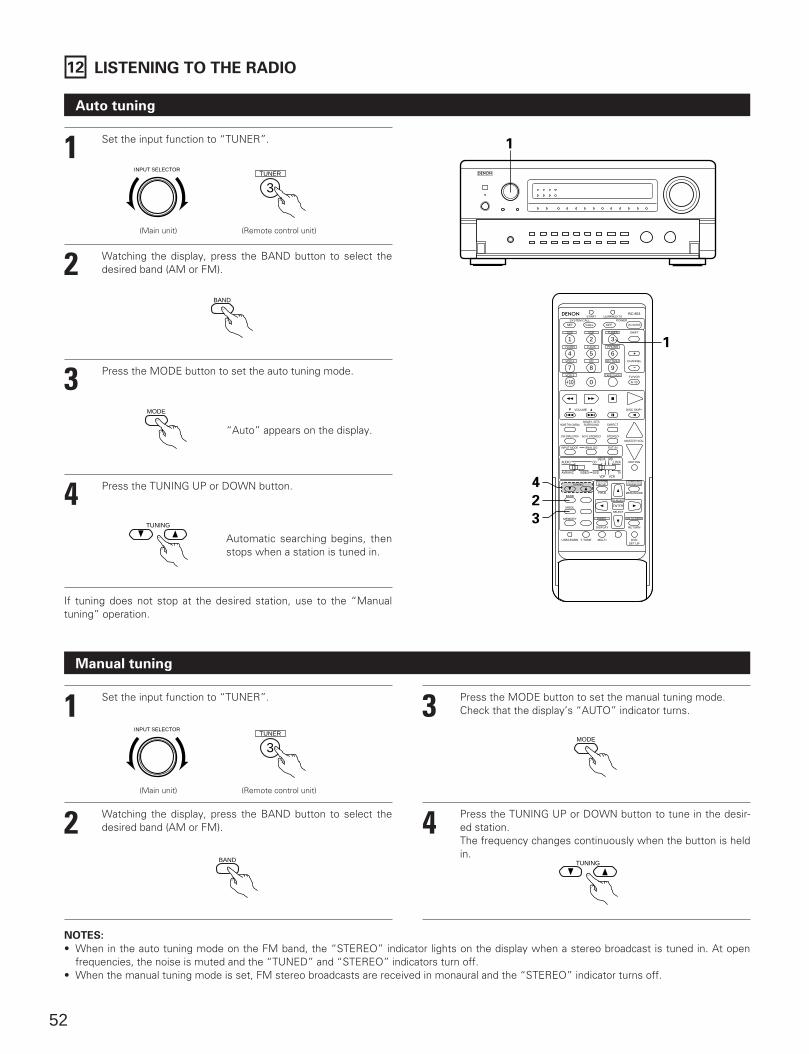
52
12 LISTENING TO THE RADIO
Auto tuning
11 Set the input function to “TUNER”.
INPUT SELECTOR
2 Watching the display, press the BAND button to select thedesired band (AM or FM).
BAND
3 Press the MODE button to set the auto tuning mode.
MODE
“Auto” appears on the display.
4 Press the TUNING UP or DOWN button.
TUNING
Automatic searching begins, thenstops when a station is tuned in.
If tuning does not stop at the desired station, use to the “Manualtuning” operation.
Manual tuning
1 Set the input function to “TUNER”.
2 Watching the display, press the BAND button to select thedesired band (AM or FM).
3 Press the MODE button to set the manual tuning mode. Check that the display’s “AUTO” indicator turns.
4 Press the TUNING UP or DOWN button to tune in the desir-ed station. The frequency changes continuously when the button is heldin.
NOTES:
• When in the auto tuning mode on the FM band, the “STEREO” indicator lights on the display when a stereo broadcast is tuned in. At openfrequencies, the noise is muted and the “TUNED” and “STEREO” indicators turn off.
• When the manual tuning mode is set, FM stereo broadcasts are received in monaural and the “STEREO” indicator turns off.
TUNER
3
DVD
START LEARNED/TX
HOME THX CINEMA
TUNING
BANDTITLE MENU/GUIDE
MODE
MEMORY
USE/LEARN T.TONE MULTI DVDSET UP
RETURN
PANEL
DISPLAY
ON SCREEN
DOLBY / DTSSURROUND DIRECT
DSP SIMULATION 5CH STEREO STEREO
INPUT MODE ANALOG EXT.IN
MUTING
MASTER VOL.
VOLUME DISC SKIP+
SYSTEM CALL POWER
VDP TUNER SHIFT
TV/DBS V.AUX PHONO
VCR-1 CD MD / TAPE-1 CHANNEL
VCR-2 TAPE-2 MON TV/VCR
AVR/AVC VIDEO DVD TV
AUDIO
VDP VCR
CDMD
LOCKDECK
SYSTEMSETUP
SURROUNDPARAMETER
CH SELECT
SELECT
RC-853
1 2 3
4
SET
A / B
CALL OFF
ENTER
ON / SOURCE
5 6
7 8 9
+10 0
4
2
3
1
INPUT SELECTORTUNER
3
BAND
MODE
TUNING
(Main unit) (Remote control unit)
(Main unit) (Remote control unit)
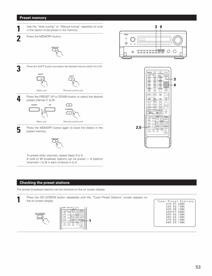
53
Preset memory
3 4
2 Press the MEMORY button.
MEMORY
3 Press the SHIFT button and select the desired memory block (A to D).
SHIFT
4 Press the PRESET UP or DOWN button to select the desiredpreset channel (1 to 8).
DOWN UP
5 Press the MEMORY button again to store the station in thepreset memory.
To preset other channels, repeat steps 2 to 5.A total of 40 broadcast stations can be preset — 8 stations(channels 1 to 8) in each of blocks A to E.
Checking the preset stations
The preset broadcast stations can be checked on the on screen display.
1 Press the ON SCREEN button repeatedly until the “Tuner Preset Stations” screen appears onthe on screen display.
RETURN
ON SCREEN
1 Use the “Auto tuning” or “Manual tuning” operation to tunein the station to be preset in the memory.
DVD
START LEARNED/TX
HOME THX CINEMA
TUNING
BANDTITLE MENU/GUIDE
MODE
MEMORY
USE/LEARN T.TONE MULTI DVDSET UP
RETURN
PANEL
DISPLAY
ON SCREEN
DOLBY / DTSSURROUND DIRECT
DSP SIMULATION 5CH STEREO STEREO
INPUT MODE ANALOG EXT.IN
MUTING
MASTER VOL.
VOLUME DISC SKIP+
SYSTEM CALL POWER
VDP TUNER SHIFT
TV/DBS V.AUX PHONO
VCR-1 CD MD / TAPE-1 CHANNEL
VCR-2 TAPE-2 MON TV/VCR
AVR/AVC VIDEO DVD TV
AUDIO
VDP VCR
CDMD
LOCKDECK
SYSTEMSETUP
SURROUNDPARAMETER
CH SELECT
SELECT
RC-853
1 2 3
4
SET
A / B
CALL OFF
ENTER
ON / SOURCE
5 6
7 8 9
+10 0
3
4
2,5
TUNING
BANDTITLE MENU/GUIDE
MODE
MEMORY
USE/LEARN T.TONE MULTI DVDSET UP
RETURN
PANEL
DISPLAY
ON SCREEN
AVR/AVC VIDEO DVD TVVDP VCR
SYSTEMSETUP
SURROUNDPARAMETER
CH SELECT
SELECT
ENTER
1
SHIFT
CHANNEL
MEMORY
(Main unit) (Remote control unit)
(Main unit) (Remote control unit)
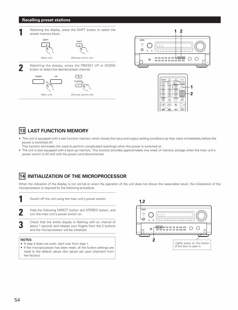
1,2
2
54
Recalling preset stations
1 Watching the display, press the SHIFT button to select thepreset memory block.
2 Watching the display, press the PRESET UP or DOWNbutton to select the desired preset channel.
1 2
13 LAST FUNCTION MEMORY
• This unit is equipped with a last function memory which stores the input and output setting conditions as they were immediately before thepower is switched off.This function eliminates the need to perform complicated resettings when the power is switched on.
• The unit is also equipped with a back-up memory. This function provides approximately one week of memory storage when the main unit’spower switch is off and with the power cord disconnected.
14 INITIALIZATION OF THE MICROPROCESSOR
When the indication of the display is not normal or when the operation of the unit does not shows the reasonable result, the initialization of themicroprocessor is required by the following procedure.
123
Switch off the unit using the main unit’s power switch.
Hold the following DIRECT button and STEREO button, andturn the main unit’s power switch on.
Check that the entire display is flashing with an interval ofabout 1 second, and release your fingers from the 2 buttonsand the microprocessor will be initialized.
NOTES:
• If step 3 does not work, start over from step 1.• If the microprocessor has been reset, all the button settings are
reset to the default values (the values set upon shipment fromthe factory).
DVD
START LEARNED/TX
DOLBY / DTS
VOLUME DISC SKIP+
SYSTEM CALL POWER
VDP TUNER SHIFT
TV/DBS V.AUX PHONO
VCR-1 CD MD / TAPE-1 CHANNEL
VCR-2 TAPE-2 MON TV/VCR
RC-853
1 2 3
4
SET
A / B
CALL OFF ON / SOURCE
5 6
7 8 9
+10 0
1
2
SHIFTSHIFT
DOWN UP
CHANNEL
Lightly press on the buttonof the door to open it.
(Main unit) (Remote control unit)
(Main unit) (Remote control unit)
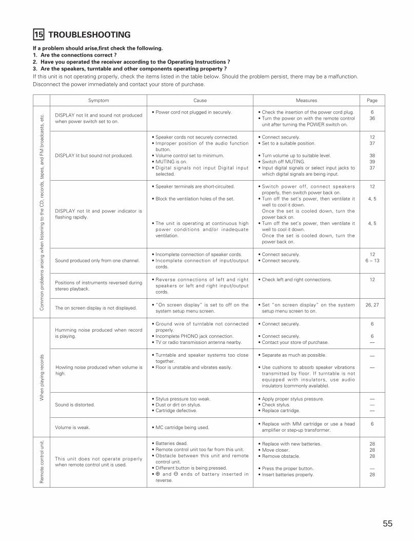
55
15 TROUBLESHOOTING
If a problem should arise,first check the following.
1. Are the connections correct ?
2. Have you operated the receiver according to the Operating Instructions ?
3. Are the speakers, turntable and other components operating property ?
If this unit is not operating properly, check the items listed in the table below. Should the problem persist, there may be a malfunction. Disconnect the power immediately and contact your store of purchase.
Symptom
DISPLAY not lit and sound not producedwhen power switch set to on.
DISPLAY lit but sound not produced.
DISPLAY not lit and power indicator isflashing rapidly.
Cause Measures
• Power cord not plugged in securely.
• Speaker cords not securely connected.• Improper position of the audio function
button.• Volume control set to minimum.• MUTING is on.• Digital signals not input Digital input
selected.
• Speaker terminals are short-circuited.
• Block the ventilation holes of the set.
• The unit is operating at continuous highpower conditions and/or inadequateventilation.
• Check the insertion of the power cord plug.• Turn the power on with the remote control
unit after turning the POWER switch on.
• Connect securely.• Set to a suitable position.
• Turn volume up to suitable level.• Switch off MUTING.• Input digital signals or select input jacks to
which digital signals are being input.
• Switch power off, connect speakersproperly, then switch power back on.
• Turn off the set’s power, then ventilate itwell to cool it down.Once the set is cooled down, turn thepower back on.
• Turn off the set’s power, then ventilate itwell to cool it down.Once the set is cooled down, turn thepower back on.
Sound produced only from one channel.• Incomplete connection of speaker cords.• Incomplete connection of input/output
cords.
• Connect securely.• Connect securely.
Page
636
1237
383937
12
4, 5
4, 5
126 ~ 13
Positions of instruments reversed duringstereo playback.
• Reverse connections of left and rightspeakers or left and right input/outputcords.
• Check left and right connections. 12
The on screen display is not displayed.• “On screen display” is set to off on the
system setup menu screen.• Set “on screen display” on the system
setup menu screen to on.26, 27
Humming noise produced when recordis playing.
• Ground wire of turntable not connectedproperly.
• Incomplete PHONO jack connection.• TV or radio transmission antenna nearby.
• Connect securely.
• Connect securely.• Contact your store of purchase.
6
6—
Howling noise produced when volume ishigh.
• Turntable and speaker systems too closetogether.
• Floor is unstable and vibrates easily.
• Separate as much as possible.
• Use cushions to absorb speaker vibrationstransmitted by floor. If turntable is notequipped with insulators, use audioinsulators (commonly available).
—
—
Sound is distorted.• Stylus pressure too weak.• Dust or dirt on stylus.• Cartridge defective.
• Apply proper stylus pressure.• Check stylus.• Replace cartridge.
———
Volume is weak. • MC cartridge being used.• Replace with MM cartridge or use a head
amplifier or step-up transformer.6
This unit does not operate properlywhen remote control unit is used.
• Batteries dead.• Remote control unit too far from this unit.• Obstacle between this unit and remote
control unit.• Different button is being pressed.• < and > ends of battery inserted in
reverse.
• Replace with new batteries.• Move closer.• Remove obstacle.
• Press the proper button.• Insert batteries properly.
282828
—28
Com
mon
pro
blem
s ar
isin
g w
hen
liste
ning
to
the
CD
, rec
ords
, tap
es, a
nd F
M b
road
cast
s, e
tc.
Whe
n pl
ayin
g re
cord
sR
emot
e co
ntro
l uni
t.
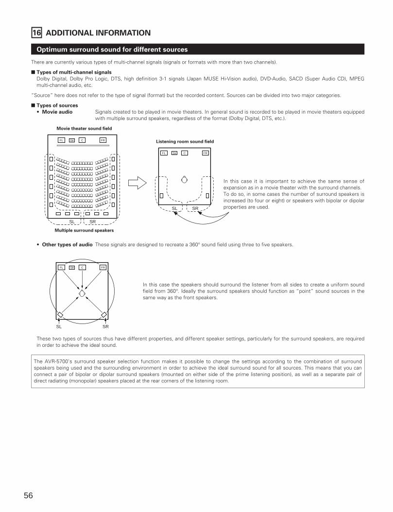
56
16 ADDITIONAL INFORMATION
There are currently various types of multi-channel signals (signals or formats with more than two channels).
2 Types of multi-channel signals
Dolby Digital, Dolby Pro Logic, DTS, high definition 3-1 signals (Japan MUSE Hi-Vision audio), DVD-Audio, SACD (Super Audio CD), MPEGmulti-channel audio, etc.
“Source” here does not refer to the type of signal (format) but the recorded content. Sources can be divided into two major categories.
2 Types of sources
• Movie audio Signals created to be played in movie theaters. In general sound is recorded to be played in movie theaters equippedwith multiple surround speakers, regardless of the format (Dolby Digital, DTS, etc.).
Optimum surround sound for different sources
FL CSW FR
FL CSW FR
SL SR
SL SR
In this case it is important to achieve the same sense ofexpansion as in a movie theater with the surround channels.To do so, in some cases the number of surround speakers isincreased (to four or eight) or speakers with bipolar or dipolarproperties are used.
Movie theater sound field
Multiple surround speakers
Listening room sound field
• Other types of audio These signals are designed to recreate a 360° sound field using three to five speakers.
FL CSW FR
SL SR
In this case the speakers should surround the listener from all sides to create a uniform soundfield from 360°. Ideally the surround speakers should function as “point” sound sources in thesame way as the front speakers.
These two types of sources thus have different properties, and different speaker settings, particularly for the surround speakers, are requiredin order to achieve the ideal sound.
The AVR-5700’s surround speaker selection function makes it possible to change the settings according to the combination of surroundspeakers being used and the surrounding environment in order to achieve the ideal surround sound for all sources. This means that you canconnect a pair of bipolar or dipolar surround speakers (mounted on either side of the prime listening position), as well as a separate pair ofdirect radiating (monopolar) speakers placed at the rear corners of the listening room.

57
Speaker setting examples
Here we describe a number of speaker settings for different purposes. Use these examples as guides to set up your system according to thetype of speakers used and the main usage purpose.
(1) Basic setting for primarily watching movies
Use this setting if your main purpose is to listen to movie music and when using one set (two speakers) of regular single-way or two-wayspeakers as the surround speakers.
• Set the front speakers with their front surfaces as flush with the TV ormonitor screen as possible. Set the center speaker between the front leftand right speakers and no further from the listening position than the frontspeakers.
• Consult the owner’s manual for your subwoofer for advice on placing thesubwoofer within the listening room.
• If the surround speakers are direct-radiating (monopolar) then place themslightly behind and at an angle to the listening position and parallel to thewalls at a position 60 to 90 centimeters (2 to 3 feet) above ear level at theprime listening position.
• Connect the surround speakers to the surround speaker A jacks on theAVR-5700 and set all settings on the setup menu to “A”. (This is thefactory default setting. For details, see page 16.)
Front speakersCenter speaker
MonitorSubwoofer
Surround speakers
As seen from above
As seen from the side
Surround speaker
Front speaker
60 to 90 cm
(2) Setting for primarily watching movies using diffusion type speakers for the surround speakers
For the greatest sense of surround sound envelopment, diffuse radiation speakers such as bipolar types, or dipolar (THX) types, provide awider dispersion than is possible to obtain from a direct radiating speaker (monopolar). Place these speakers at either side of the primelistening position, mounted above ear level.
• Set the front speakers, center speaker and subwoofer in the samepositions as in example (1).
• Set the surround speakers directly at the sides of the listening positionand 60 to 90 centimeters (2 to 3 feet) above ear level.
• Connect the surround speakers to the surround speaker A jacks on theAVR-5700 and set all settings on the setup menu to “A”. (This is thefactory default setting. For details, see page 16.)
• The signals from the surround channels reflect off the walls as shown onthe diagram at the left, creating an enveloping and realistic surround soundpresentation.For multi-channel music sources however, the use of bipolar or dipolar
As seen from the side
Surround speaker
Front speaker
60 to 90 cm
Path of the surround sound from the
speakers to the listening position
As seen from above
(3) When using different surround speakers for movies and music
To achieve more effective surround sound for both movies and music, use different sets of surround speakers and different surround modesfor the two types of sources.
As seen from the side
Surround speakers A
Surroundspeakers B
Front speaker
60 to 90 cmAs seen from above
• Set the front speakers slightly wider apart than the setup for watching movies only and point them toward the listeningposition in order assure clear positioning of the sound.
• Set the center speaker in the same positions as in example (1).• Set surround speakers A for watching movies in the positions described in example (1) or (2), depending on the types
of speakers used.• Set surround speakers B for playing multi-channel music at the same height as the front speakers and slightly at an
angle to the rear of the listening position, and point them toward the listening position.• Connect the surround speakers for watching movies to the surround speaker A jacks on the AVR-5700, the surround
speakers for playing multi-channel music to the surround speaker B jacks. Set the surround speaker selection on thesetup menu. (For instructions, see page 18.)
• To activate the appropriate speakers for movies and music, we suggest that during setup, choose Dolby Digital/DTSwith THX and Surround Speakers A (the bipolar or dipolar speakers mounted at the sides of the listening position).
Front speakersCenter speaker
MonitorSubwoofer
Surround speakers B
Surround speakers A
2 The speakers can be switched at the touch of a button by turning HOME THX CINEMA on when playing movies and off when playing multi-channel music.
The surround speakers can be switched freely during playback with the surround parameter adjustment. (For instructions, see page 46.)
45°
120°
45° ~ 60°
140°
Choose Dolby Digital/DTS without THX and Surround Speakers B (thedirect radiating speakers mounted at the rear corners of the listeningroom). Then, by simply activating the THX function (used during movieplayback, the Surround A speakers are automatically activated. For multi-channel music listening (Dolby Digital or DTS music programs), turn off theTHX enhancements by touching the THX button on the remote control,and the Surround B speakers will be automatically activated.
Example: Movie sources (Dolby, DTS surround, etc.)“THX” or “THX 5.1” mode: Speakers A
Music sources (DVD video, DTS CD, etc.)“Dolby/DTS surround”: Speakers B
speakers mounted at the sides of the listening position may not be satifactory in order to create a coherent 360 degreesurround sound field. Connect another pair of direct radiating speakers as described in example (3) and place them atthe rear corners of the room facing towards the prime listening position.
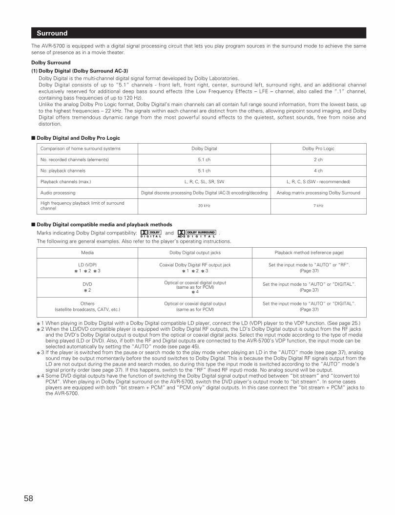
58
Surround
The AVR-5700 is equipped with a digital signal processing circuit that lets you play program sources in the surround mode to achieve the samesense of presence as in a movie theater.
Dolby Surround
(1) Dolby Digital (Dolby Surround AC-3)
Dolby Digital is the multi-channel digital signal format developed by Dolby Laboratories. Dolby Digital consists of up to “5.1” channels - front left, front right, center, surround left, surround right, and an additional channelexclusively reserved for additional deep bass sound effects (the Low Frequency Effects – LFE – channel, also called the “.1” channel,containing bass frequencies of up to 120 Hz). Unlike the analog Dolby Pro Logic format, Dolby Digital’s main channels can all contain full range sound information, from the lowest bass, upto the highest frequencies – 22 kHz. The signals within each channel are distinct from the others, allowing pinpoint sound imaging, and DolbyDigital offers tremendous dynamic range from the most powerful sound effects to the quietest, softest sounds, free from noise anddistortion.
2 Dolby Digital and Dolby Pro Logic
Comparison of home surround systems
No. recorded channels (elements)
No. playback channels
Playback channels (max.)
Audio processing
High frequency playback limit of surroundchannel
Dolby Digital
5.1 ch
5.1 ch
L, R, C, SL, SR, SW
Digital discrete processing Dolby Digital (AC-3) encoding/decoding
20 kHz
Dolby Pro Logic
2 ch
4 ch
L, R, C, S (SW - recommended)
Analog matrix processing Dolby Surround
7 kHz
2 Dolby Digital compatible media and playback methods
Marks indicating Dolby Digital compatibility: and .
The following are general examples. Also refer to the player’s operating instructions.
Media
LD (VDP)2 1 2 2 2 3
DVD2 2
Others(satellite broadcasts, CATV, etc.)
Dolby Digital output jacks
Coaxial Dolby Digital RF output jack2 1 2 2 2 3
Optical or coaxial digital output (same as for PCM)
2 4
Optical or coaxial digital output (same as for PCM)
Playback method (reference page)
Set the input mode to “AUTO” or “RF”.(Page 37)
Set the input mode to “AUTO” or “DIGITAL”.(Page 37)
Set the input mode to “AUTO” or “DIGITAL”.(Page 37)
2 1 When playing in Dolby Digital with a Dolby Digital compatible LD player, connect the LD (VDP) player to the VDP function. (See page 25.)2 2 When the LD/DVD compatible player is equipped with Dolby Digital RF outputs, the LD’s Dolby Digital output is output from the RF jacks
and the DVD’s Dolby Digital output is output from the optical or coaxial digital jacks. Select the input mode according to the type of mediabeing played (LD or DVD). Also, if both the RF and Digital outputs are connected to the AVR-5700’s VDP function, the input mode can beselected automatically by setting the “AUTO” mode (see page 45).
2 3 If the player is switched from the pause or search mode to the play mode when playing an LD in the “AUTO” mode (see page 37), analogsound may be output momentarily before the sound switches to Dolby Digital. This is because the Dolby Digital RF signals output from theLD are not output during the pause and search modes, so during this type the input mode is switched according to the “AUTO” mode’ssignal priority order (see page 37). If this happens, switch to the “RF” (fixed RF input) mode. No analog sound will be output.
2 4 Some DVD digital outputs have the function of switching the Dolby Digital signal output method between “bit stream” and “(convert to)PCM”. When playing in Dolby Digital surround on the AVR-5700, switch the DVD player’s output mode to “bit stream”. In some casesplayers are equipped with both “bit stream + PCM” and “PCM only” digital outputs. In this case connect the “bit stream + PCM” jacks tothe AVR-5700.
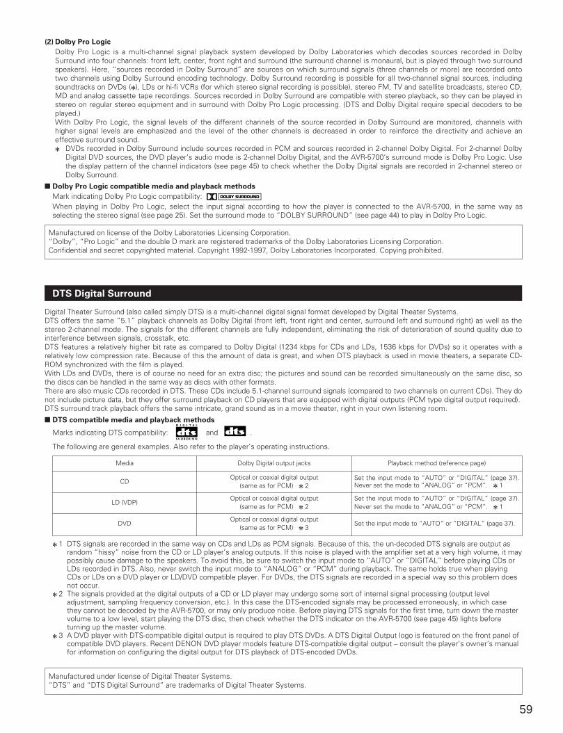
59
(2) Dolby Pro Logic
Dolby Pro Logic is a multi-channel signal playback system developed by Dolby Laboratories which decodes sources recorded in DolbySurround into four channels: front left, center, front right and surround (the surround channel is monaural, but is played through two surroundspeakers). Here, “sources recorded in Dolby Surround” are sources on which surround signals (three channels or more) are recorded ontotwo channels using Dolby Surround encoding technology. Dolby Surround recording is possible for all two-channel signal sources, includingsoundtracks on DVDs (2), LDs or hi-fi VCRs (for which stereo signal recording is possible), stereo FM, TV and satellite broadcasts, stereo CD,MD and analog cassette tape recordings. Sources recorded in Dolby Surround are compatible with stereo playback, so they can be played instereo on regular stereo equipment and in surround with Dolby Pro Logic processing. (DTS and Dolby Digital require special decoders to beplayed.)With Dolby Pro Logic, the signal levels of the different channels of the source recorded in Dolby Surround are monitored, channels withhigher signal levels are emphasized and the level of the other channels is decreased in order to reinforce the directivity and achieve aneffective surround sound.2 DVDs recorded in Dolby Surround include sources recorded in PCM and sources recorded in 2-channel Dolby Digital. For 2-channel Dolby
Digital DVD sources, the DVD player’s audio mode is 2-channel Dolby Digital, and the AVR-5700’s surround mode is Dolby Pro Logic. Usethe display pattern of the channel indicators (see page 45) to check whether the Dolby Digital signals are recorded in 2-channel stereo orDolby Surround.
2 Dolby Pro Logic compatible media and playback methods
Mark indicating Dolby Pro Logic compatibility: When playing in Dolby Pro Logic, select the input signal according to how the player is connected to the AVR-5700, in the same way asselecting the stereo signal (see page 25). Set the surround mode to “DOLBY SURROUND” (see page 44) to play in Dolby Pro Logic.
Manufactured on license of the Dolby Laboratories Licensing Corporation. “Dolby”, “Pro Logic” and the double D mark are registered trademarks of the Dolby Laboratories Licensing Corporation. Confidential and secret copyrighted material. Copyright 1992-1997, Dolby Laboratories Incorporated. Copying prohibited.
Digital Theater Surround (also called simply DTS) is a multi-channel digital signal format developed by Digital Theater Systems.DTS offers the same “5.1” playback channels as Dolby Digital (front left, front right and center, surround left and surround right) as well as thestereo 2-channel mode. The signals for the different channels are fully independent, eliminating the risk of deterioration of sound quality due tointerference between signals, crosstalk, etc.DTS features a relatively higher bit rate as compared to Dolby Digital (1234 kbps for CDs and LDs, 1536 kbps for DVDs) so it operates with arelatively low compression rate. Because of this the amount of data is great, and when DTS playback is used in movie theaters, a separate CD-ROM synchronized with the film is played.With LDs and DVDs, there is of course no need for an extra disc; the pictures and sound can be recorded simultaneously on the same disc, sothe discs can be handled in the same way as discs with other formats.There are also music CDs recorded in DTS. These CDs include 5.1-channel surround signals (compared to two channels on current CDs). They donot include picture data, but they offer surround playback on CD players that are equipped with digital outputs (PCM type digital output required).DTS surround track playback offers the same intricate, grand sound as in a movie theater, right in your own listening room.
2 DTS compatible media and playback methods
Marks indicating DTS compatibility: and .
The following are general examples. Also refer to the player’s operating instructions.
Media
CD
LD (VDP)
DVD
Dolby Digital output jacks
Optical or coaxial digital output (same as for PCM) 2 2
Optical or coaxial digital output (same as for PCM) 2 2
Optical or coaxial digital output (same as for PCM) 2 3
Playback method (reference page)
Set the input mode to “AUTO” or “DIGITAL” (page 37).Never set the mode to “ANALOG” or “PCM”. 2 1
Set the input mode to “AUTO” or “DIGITAL” (page 37).Never set the mode to “ANALOG” or “PCM”. 2 1
Set the input mode to “AUTO” or “DIGITAL” (page 37).
2 1 DTS signals are recorded in the same way on CDs and LDs as PCM signals. Because of this, the un-decoded DTS signals are output asrandom “hissy” noise from the CD or LD player’s analog outputs. If this noise is played with the amplifier set at a very high volume, it maypossibly cause damage to the speakers. To avoid this, be sure to switch the input mode to “AUTO” or “DIGITAL” before playing CDs orLDs recorded in DTS. Also, never switch the input mode to “ANALOG” or “PCM” during playback. The same holds true when playingCDs or LDs on a DVD player or LD/DVD compatible player. For DVDs, the DTS signals are recorded in a special way so this problem doesnot occur.
2 2 The signals provided at the digital outputs of a CD or LD player may undergo some sort of internal signal processing (output leveladjustment, sampling frequency conversion, etc.). In this case the DTS-encoded signals may be processed erroneously, in which casethey cannot be decoded by the AVR-5700, or may only produce noise. Before playing DTS signals for the first time, turn down the mastervolume to a low level, start playing the DTS disc, then check whether the DTS indicator on the AVR-5700 (see page 45) lights beforeturning up the master volume.
2 3 A DVD player with DTS-compatible digital output is required to play DTS DVDs. A DTS Digital Output logo is featured on the front panel ofcompatible DVD players. Recent DENON DVD player models feature DTS-compatible digital output – consult the player’s owner’s manualfor information on configuring the digital output for DTS playback of DTS-encoded DVDs.
Manufactured under license of Digital Theater Systems. “DTS” and “DTS Digital Surround” are trademarks of Digital Theater Systems.
DTS Digital Surround
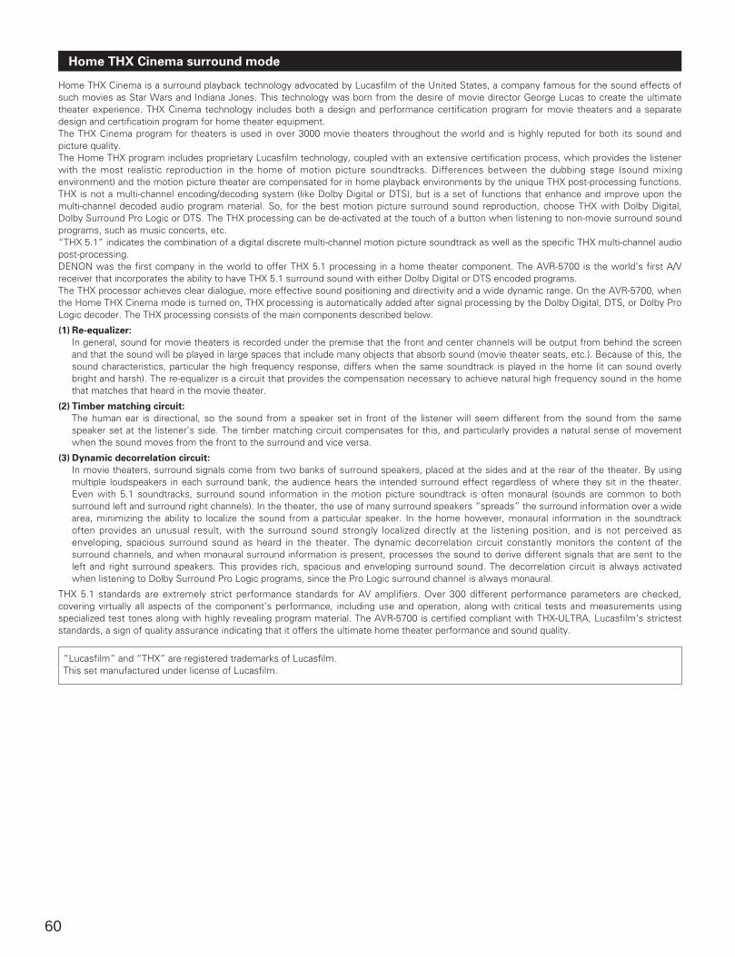
60
Home THX Cinema is a surround playback technology advocated by Lucasfilm of the United States, a company famous for the sound effects ofsuch movies as Star Wars and Indiana Jones. This technology was born from the desire of movie director George Lucas to create the ultimatetheater experience. THX Cinema technology includes both a design and performance certification program for movie theaters and a separatedesign and certificatioin program for home theater equipment.The THX Cinema program for theaters is used in over 3000 movie theaters throughout the world and is highly reputed for both its sound andpicture quality.The Home THX program includes proprietary Lucasfilm technology, coupled with an extensive certification process, which provides the listenerwith the most realistic reproduction in the home of motion picture soundtracks. Differences between the dubbing stage (sound mixingenvironment) and the motion picture theater are compensated for in home playback environments by the unique THX post-processing functions.THX is not a multi-channel encoding/decoding system (like Dolby Digital or DTS), but is a set of functions that enhance and improve upon themulti-channel decoded audio program material. So, for the best motion picture surround sound reproduction, choose THX with Dolby Digital,Dolby Surround Pro Logic or DTS. The THX processing can be de-activated at the touch of a button when listening to non-movie surround soundprograms, such as music concerts, etc.“THX 5.1” indicates the combination of a digital discrete multi-channel motion picture soundtrack as well as the specific THX multi-channel audiopost-processing.DENON was the first company in the world to offer THX 5.1 processing in a home theater component. The AVR-5700 is the world’s first A/Vreceiver that incorporates the ability to have THX 5.1 surround sound with either Dolby Digital or DTS encoded programs. The THX processor achieves clear dialogue, more effective sound positioning and directivity and a wide dynamic range. On the AVR-5700, whenthe Home THX Cinema mode is turned on, THX processing is automatically added after signal processing by the Dolby Digital, DTS, or Dolby ProLogic decoder. The THX processing consists of the main components described below.
(1) Re-equalizer:
In general, sound for movie theaters is recorded under the premise that the front and center channels will be output from behind the screenand that the sound will be played in large spaces that include many objects that absorb sound (movie theater seats, etc.). Because of this, thesound characteristics, particular the high frequency response, differs when the same soundtrack is played in the home (it can sound overlybright and harsh). The re-equalizer is a circuit that provides the compensation necessary to achieve natural high frequency sound in the homethat matches that heard in the movie theater.
(2) Timber matching circuit:
The human ear is directional, so the sound from a speaker set in front of the listener will seem different from the sound from the samespeaker set at the listener’s side. The timber matching circuit compensates for this, and particularly provides a natural sense of movementwhen the sound moves from the front to the surround and vice versa.
(3) Dynamic decorrelation circuit:
In movie theaters, surround signals come from two banks of surround speakers, placed at the sides and at the rear of the theater. By usingmultiple loudspeakers in each surround bank, the audience hears the intended surround effect regardless of where they sit in the theater.Even with 5.1 soundtracks, surround sound information in the motion picture soundtrack is often monaural (sounds are common to bothsurround left and surround right channels). In the theater, the use of many surround speakers “spreads” the surround information over a widearea, minimizing the ability to localize the sound from a particular speaker. In the home however, monaural information in the soundtrackoften provides an unusual result, with the surround sound strongly localized directly at the listening position, and is not perceived asenveloping, spacious surround sound as heard in the theater. The dynamic decorrelation circuit constantly monitors the content of thesurround channels, and when monaural surround information is present, processes the sound to derive different signals that are sent to theleft and right surround speakers. This provides rich, spacious and enveloping surround sound. The decorrelation circuit is always activatedwhen listening to Dolby Surround Pro Logic programs, since the Pro Logic surround channel is always monaural.
THX 5.1 standards are extremely strict performance standards for AV amplifiers. Over 300 different performance parameters are checked,covering virtually all aspects of the component’s performance, including use and operation, along with critical tests and measurements usingspecialized test tones along with highly revealing program material. The AVR-5700 is certified compliant with THX-ULTRA, Lucasfilm’s stricteststandards, a sign of quality assurance indicating that it offers the ultimate home theater performance and sound quality.
“Lucasfilm” and “THX” are registered trademarks of Lucasfilm.This set manufactured under license of Lucasfilm.
Home THX Cinema surround mode
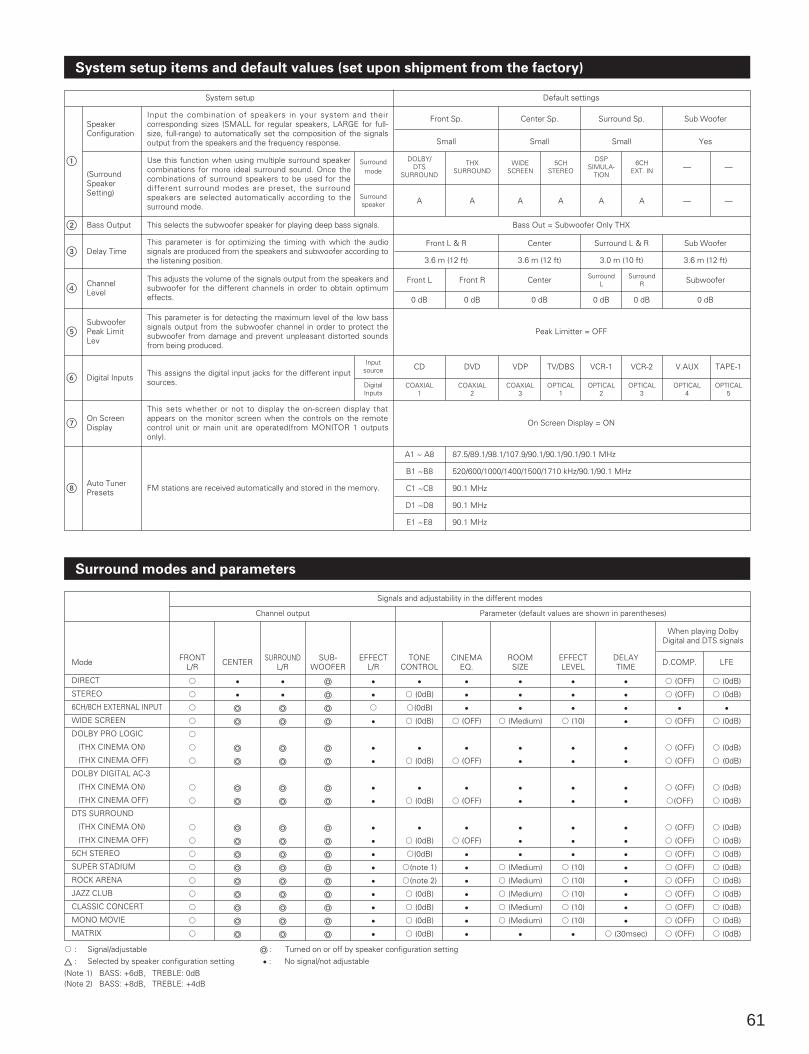
61
System setup items and default values (set upon shipment from the factory)
FRONTL/R
A
A
A
A
A
A
A
A
A
A
A
A
A
A
A
A
A
A
E
E
o
o
o
o
o
o
o
o
o
o
o
o
o
o
o
E
E
o
o
o
o
o
o
o
o
o
o
o
o
o
o
o
o
o
o
o
o
o
o
o
o
o
o
o
o
o
o
o
o
E
E
A
E
E
E
E
E
E
E
E
E
E
E
E
E
E
E
A (0dB)
A(0dB)
A (0dB)
E
A (0dB)
E
A (0dB)
E
A (0dB)
A(0dB)
A(note 1)
A(note 2)
A (0dB)
A (0dB)
A (0dB)
A (0dB)
E
E
E
A (OFF)
E
A (OFF)
E
A (OFF)
E
A (OFF)
E
E
E
E
E
E
E
E
E
E
A (Medium)
E
E
E
E
E
E
E
A (Medium)
A (Medium)
A (Medium)
A (Medium)
A (Medium)
E
E
E
E
A (10)
E
E
E
E
E
E
E
A (10)
A (10)
A (10)
A (10)
A (10)
E
E
E
E
E
E
E
E
E
E
E
E
E
E
E
E
E
A (30msec)
A (OFF)
A (OFF)
E
A (OFF)
A (OFF)
A (OFF)
A (OFF)
A(OFF)
A (OFF)
A (OFF)
A (OFF)
A (OFF)
A (OFF)
A (OFF)
A (OFF)
A (OFF)
A (OFF)
A (0dB)
A (0dB)
E
A (0dB)
A (0dB)
A (0dB)
A (0dB)
A (0dB)
A (0dB)
A (0dB)
A (0dB)
A (0dB)
A (0dB)
A (0dB)
A (0dB)
A (0dB)
A (0dB)
CENTER SURROUNDL/R
SUB-WOOFER
EFFECTL/R
TONECONTROL
CINEMAEQ.
ROOMSIZE
EFFECTLEVEL
DELAYTIME
When playing DolbyDigital and DTS signals
D.COMP. LFEMode
Signals and adjustability in the different modes
Channel output Parameter (default values are shown in parentheses)
DIRECT
STEREO
6CH/8CH EXTERNAL INPUT
WIDE SCREEN
DOLBY PRO LOGIC
(THX CINEMA ON)
(THX CINEMA OFF)
DOLBY DIGITAL AC-3
(THX CINEMA ON)
(THX CINEMA OFF)
DTS SURROUND
(THX CINEMA ON)
(THX CINEMA OFF)
5CH STEREO
SUPER STADIUM
ROCK ARENA
JAZZ CLUB
CLASSIC CONCERT
MONO MOVIE
MATRIX
A : Signal/adjustableC : Selected by speaker configuration setting
o : Turned on or off by speaker configuration setting
E : No signal/not adjustable
Surround modes and parameters
Default settings
Input the combination of speakers in your system and theircorresponding sizes (SMALL for regular speakers, LARGE for full-size, full-range) to automatically set the composition of the signalsoutput from the speakers and the frequency response.
Use this function when using multiple surround speakercombinations for more ideal surround sound. Once thecombinations of surround speakers to be used for thedifferent surround modes are preset, the surroundspeakers are selected automatically according to thesurround mode.
This selects the subwoofer speaker for playing deep bass signals.
This parameter is for optimizing the timing with which the audiosignals are produced from the speakers and subwoofer according tothe listening position.
This adjusts the volume of the signals output from the speakers andsubwoofer for the different channels in order to obtain optimumeffects.
This parameter is for detecting the maximum level of the low basssignals output from the subwoofer channel in order to protect thesubwoofer from damage and prevent unpleasant distorted soundsfrom being produced.
This assigns the digital input jacks for the different inputsources.
This sets whether or not to display the on-screen display thatappears on the monitor screen when the controls on the remotecontrol unit or main unit are operated(from MONITOR 1 outputsonly).
FM stations are received automatically and stored in the memory.
Front Sp.
Small
DOLBY/DTS
SURROUND
A
Center Sp.
Small
Surround Sp.
Small
Sub Woofer
Yes
System setup
SpeakerConfiguration
(SurroundSpeakerSetting)
Bass Output
Delay Time
ChannelLevel
SubwooferPeak LimitLev
Digital Inputs
On ScreenDisplay
Auto TunerPresets
1
2
3
4
5
6
7
8
Surroundmode
Surroundspeaker
THXSURROUND
A
WIDESCREEN
A
5CHSTEREO
A
DSPSIMULA-
TION
A
6CHEXT. IN
A
—
—
—
—
Bass Out = Subwoofer Only THX
Front L & R
3.6 m (12 ft)
Center
3.6 m (12 ft)
Center
0 dB
Surround L & R
3.0 m (10 ft)
Sub Woofer
3.6 m (12 ft)
Subwoofer
0 dB
Front L
0 dB
Front R
0 dB
SurroundL
0 dB
SurroundR
0 dB
Peak Limitter = OFF
Inputsource
DigitalInputs
CD
COAXIAL1
DVD
COAXIAL2
VDP
COAXIAL3
TV/DBS
OPTICAL1
VCR-1
OPTICAL2
VCR-2
OPTICAL3
V.AUX
OPTICAL4
TAPE-1
OPTICAL5
On Screen Display = ON
A1 ~ A8
B1 ~B8
C1 ~C8
D1 ~D8
E1 ~E8
87.5/89.1/98.1/107.9/90.1/90.1/90.1/90.1 MHz
520/600/1000/1400/1500/1710 kHz/90.1/90.1 MHz
90.1 MHz
90.1 MHz
90.1 MHz
(Note 1) BASS: +6dB, TREBLE: 0dB(Note 2) BASS: +8dB, TREBLE: +4dB
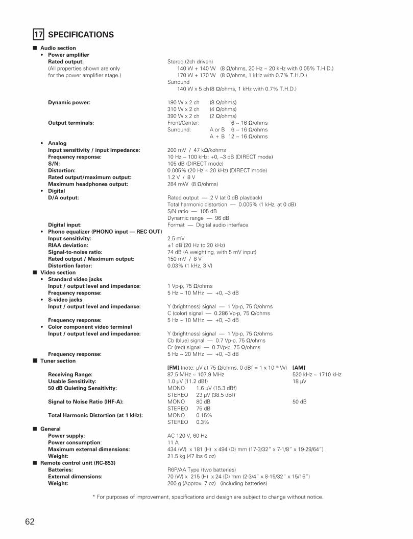
62
17 SPECIFICATIONS
2 Audio section
• Power amplifier
Rated output: Stereo (2ch driven) (All properties shown are only 140 W + 140 W (8 Ω/ohms, 20 Hz ~ 20 kHz with 0.05% T.H.D.)for the power amplifier stage.) 170 W + 170 W (8 Ω/ohms, 1 kHz with 0.7% T.H.D.)
Surround140 W x 5 ch (8 Ω/ohms, 1 kHz with 0.7% T.H.D.)
Dynamic power: 190 W x 2 ch (8 Ω/ohms)310 W x 2 ch (4 Ω/ohms)390 W x 2 ch (2 Ω/ohms)
Output terminals: Front/Center: 16 ~ 16 Ω/ohms Surround: A or B 16 ~ 16 Ω/ohms
A + B 12 ~ 16 Ω/ohms• Analog
Input sensitivity / input impedance: 200 mV / 47 kΩ/kohms Frequency response: 10 Hz ~ 100 kHz: +0, –3 dB (DIRECT mode) S/N: 105 dB (DIRECT mode) Distortion: 0.005% (20 Hz ~ 20 kHz) (DIRECT mode) Rated output/maximum output: 1.2 V / 8 V Maximum headphones output: 284 mW (8 Ω/ohms)
• Digital
D/A output: Rated output — 2 V (at 0 dB playback) Total harmonic distortion — 0.005% (1 kHz, at 0 dB) S/N ratio — 105 dB Dynamic range — 96 dB
Digital input: Format — Digital audio interface • Phono equalizer (PHONO input — REC OUT)
Input sensitivity: 2.5 mVRIAA deviation: ±1 dB (20 Hz to 20 kHz)Signal-to-noise ratio: 74 dB (A weighting, with 5 mV input)Rated output / Maximum output: 150 mV / 8 V Distortion factor: 0.03% (1 kHz, 3 V)
2 Video section
• Standard video jacks
Input / output level and impedance: 1 Vp-p, 75 Ω/ohms Frequency response: 5 Hz ~ 10 MHz — +0, –3 dB
• S-video jacks
Input / output level and impedance: Y (brightness) signal — 1 Vp-p, 75 Ω/ohms C (color) signal — 0.286 Vp-p, 75 Ω/ohms
Frequency response: 5 Hz ~ 10 MHz — +0, –3 dB • Color component video terminal
Input / output level and impedance: Y (brightness) signal — 1 Vp-p, 75 Ω/ohms Cb (blue) signal — 0.7 Vp-p, 75 Ω/ohms Cr (red) signal — 0.7Vp-p, 75 Ω/ohms
Frequency response: 5 Hz ~ 20 MHz — +0, –3 dB 2 Tuner section
[FM] (note: µV at 75 Ω/ohms, 0 dBf = 1 x 10–15 W) [AM]
Receiving Range: 87.5 MHz ~ 107.9 MHz 520 kHz ~ 1710 kHz Usable Sensitivity: 1.0 µV (11.2 dBf) 18 µV50 dB Quieting Sensitivity: MONO 1.6 µV (15.3 dBf)
STEREO 23 µV (38.5 dBf)Signal to Noise Ratio (IHF-A): MONO 80 dB 50 dB
STEREO 75 dBTotal Harmonic Distortion (at 1 kHz): MONO 0.15%
STEREO 0.3%2 General
Power supply: AC 120 V, 60 Hz Power consumption: 11 A Maximum external dimensions: 434 (W) x 181 (H) x 494 (D) mm (17-3/32” x 7-1/8” x 19-29/64”)Weight: 21.5 kg (47 lbs 6 oz)
2 Remote control unit (RC-853)
Batteries: R6P/AA Type (two batteries) External dimensions: 70 (W) x 215 (H) x 24 (D) mm (2-3/4” x 8-15/32” x 15/16”) Weight: 200 g (Approx. 7 oz) (including batteries)
* For purposes of improvement, specifications and design are subject to change without notice.


Printed in Japan. 511 3418 005 901
14-14, AKASAKA 4-CHOME, MINATO-KU, TOKYO 107-8011, JAPANTelephone: (03) 3584-8111
Cable: NIPPON COLUMBIA TOKYO Telex: JAPANOLA J22591